1
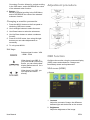
TVM-1700 / TVM-1900 / TVM2200 Monitors User Manual P/N 1079200A-EN • REV 1.2 • ISS 10JAN12 Copyright European Union directive © 2012 UTC Fire & Security. All rights reserved 2004/108/EC (EMC directive): Hereby, UTC Fire & Security declares that this device is in compliance with the essential requirements and other relevant provisions of Directive 2004/108/EC. Trademarks and patents Interlogix, TruVision brands and logos are trademarks of UTC Fire & Security. Other trade names used in this document may be trademarks or registered trademarks of the manufacturers or vendors of the respective products.. Manufacturer Authorized EU manufacturing representative: UTC Fire & Security B.V. Kelvinstraat 7, 6003 DH Weert, The Netherlands 2002/96/EC (WEEE directive): Products marked with this symbol cannot be disposed of as unsorted municipal waste in the European Union. For proper recycling, return this product to your local supplier upon the purchase of equivalent new equipment, or dispose of it at designated collection points. For more information see: www.recyclethis.info. Certification Contact information UTC Fire & Security Americas Corporation, Inc. 2955 Red Hill Avenue, Costa Mesa, CA 92626-5923, USA N4131 FCC compliance Class A: This equipment has been tested and found to comply with the limits for a Class A digital device, pursuant to part 15 of the FCC Rules. These limits are designed to provide reasonable protection against harmful interference when the equipment is operated in a commercial environment. This equipment generates, uses, and can radiate radio frequency energy and, if not installed and used in accordance with the instruction manual, may cause harmful interference to radio communications. Operation of this equipment in a residential area is likely to cause harmful interference in which case the user will be required to correct the interference at his own expense. ACMA compliance Notice! This is a Class A product. In a domestic environment this product may cause radio interference in which case the user may be required to take adequate measures. Canada This Class A digital apparatus complies with Canadian ICES003. Cet appareil numérique de la classe A est conforme à la norme NMB-0330 du Canada. For contact information see: www.interlogix.com or www.utcfssecurityproducts.eu. Content Important safeguards 2 Introduction 2 Features 2 Assembling the monitor 3 Assembling the monitor 3 Connections 3 Front panel controls 4 Control panel (TVM-1700/TVM-1900 model) 4 Control panel (TVM-2200 model) 4 Changing a monitor parameter 5 Hot keys 5 Adjustment procedure 5 OSD function 5 VGA menu (HDMI) 5 CAM menu 7 Self-diagnosis 8 Removing the monitor stand 8 Attaching the monitor stand 9 Troubleshooting 9 Specifications 11 TVM-1700/TVM-1900 models 11 TVM-2200 models 12 Factory preset timings 13 TVM-1700/TVM-1900 models 13 TVM-2200 models 14 User Manual 1 EN Important safeguards circumstances if the monitor will not be used for a long period of time, if the power supply cable or plug/connector is damaged or if the monitor housing is damaged or broken. 1. Installation cautions: • Do not block any ventilation openings. • Always ensure that the monitor is located in a well-ventilated area to prevent the unit from overheating. • Only use accessories specified by the manufacturer or those sold with the product. • Avoid operating or placing the monitor in the following environments: extremes of temperatures, both hot and cold; high humidity; direct sunlight; excessively dusty surroundings; avoid close proximity to other equipment that generates a strong magnetic field 2. Water and moisture: Do not use this appliance near water. To reduce the risk of fire or electric shock, do not expose this unit to rain or moisture. 3. Power cord and power cord protection: Power cords should be routed so that they not likely to be walked on or pinched. Pay particular attention to the location of cords and plugs, convenience receptacles, and the point of exit from the appliance. 4. Product care: Do not touch the screen directly with fingers. The oils from your skin may leave marks on the surface of the screen, which are difficult to be removed and may damage the screen permanently. Do not apply pressure to the screen. 5. Cleaning: Clean only with a dry cloth. 6. Servicing: Do not attempt to service this unit yourself. Opening or removing covers may expose you to dangerous voltage or other hazards. Refer all servicing to qualified service personnel. 7. Lightning: For added protection during a lighting storm or when this unit is left unattended and unused for long periods of time, unplug the unit from the wall outlet and disconnect the cable system. This will prevent damage to the unit due to lightning and power line surges. 8. Mains plug (2 pin/3 pin): • Do not remove the grounding or earth connection from the power supply / mains plug. • Always remember to unplug the monitor from the power supply under the following EN 2 CAUTION: Do not attempt to dismantle this product. Any attempt to dismantle or remove the covers from this product will invalidate the warranty and may also result in serious injury. Introduction This manual explains how to correctly install, operate and get the best performance from your monitor. Please read this user manual carefully before installing your monitor then keep it near your monitor for quick reference. First, please check that the contents of the box correspond with the following checklist: • LCD monitor • Power cord • AC adaptor • User manual If any item is missing or damaged, please contact your dealer. Please keep the box and packing materials so that you may properly store or transport your monitor. Features The monitor is designed for use in a small work area or for those who need more work space on the desk. The convenient and user-friendly on-screen display allows for easy and accurate adjustments of screen size, position and screen color. The monitor complies with the VESA Display Data Channel (DDC) specification for Plug and Play compatibility. Advanced microcircuitry makes setup and configuration fast and effortless. The monitor features Advanced Color Controls for fine-tuning to meet your own personal tastes or application requirements. Use the on-screen controls to adjust the color temperature, RGB gain value for the best possible screen color and intensity. User Manual Press the Menu button and activate the SelfDiagnosis menu to determine whether your monitor is functioning normally, not receiving a signal or is receiving a signal that is out of scanning range. Activate the higher refresh rates of the monitor to stabilize the screen and eliminate the annoying flicker that contributes to eye-strain and headaches. The monitor supports the optimal display performance with 1280 x 1024 @ 75 Hz (TVM1700/TVM-1900 Model) and 1680 x 1050 @ 60 Hz (TVM-2200 Model). The monitor can be connected to various types of video devices with supporting video input signals like Composite video (CVBS), Separate video. The internal stereo speakers make the end user enjoy audio sound. Assembling the monitor Disassembling the monitor 1. Put a smooth pad or cloth on a level surface. Place the monitor on it facing downwards. 2. Using a screwdriver or a similar object with a sharp end, carefully detach the supporting arm from the foot by pressing the groove on the back of the supporting arm. (Note that the fixation point can be broken if too much force is applied). TVM-1700/TVM-1900 models TVM-2200 model The monitors are designed for use on a desktop. The arm of the monitor stand is shipped preinstalled on the monitor. Assembling the monitor 1. Put a smooth pad or cloth on a level surface. Place the monitor on it facing downwards. 2. Insert the arm of the monitor stand of the monitor into the pedestral foot provided. Connections TVM-1700/TVM-1900 models 1. DC 12V Input 2. VIDEO OUT Composite signal output Arm of the monitor stand TVM-2200 model Pedestral foot 3. VIDEO IN Composite signal input. 4. AUDIO L Audio signal input left. 5. AUDIO R Audio signal input right. 6. PC Stereo Input 7. Head Phone Out 8. HDMI HDMI signal input. User Manual 3 EN Press the UP or DOWN arrow to scroll through the available sources, and press LEFT or RIGHT arrow to confirm selection. 9. VGA RGB signal input. Front panel controls (*) = Hot key Control panel (TVM-2200 model) Control panel (TVM-1700/TVM-1900 models) 1 POWER Indicator Shows both normal operation and power management status with power LED. 1. POWER Indicator Shows both normal operation and power management status with power LED. POWER Button Switches the monitor on and off. 2 POWER Switches the monitor on and off. 3 Right Arrow - Volume (*) 2. Sensor window Remote control. Receives signal from the remote controller. Primary Function: Used to increase the volume. 3. VOLUME (*) Selects the menu. Selects menu. Secondary Function: Moves cursor to the right in the OSD (On-Screen Display) window and increases the value of any selected menu. 4 Primary Function: Used to increase the volume. Secondary Function: Moves cursor to the right in the OSD window and increases the value of any selected menu. Left Arrow - Volume (*) Selects menu Primary Function: Used to decrease the volume. 4. Secondary Function: Moves cursor to the left in the OSD window and decreases the value of any selected menu. 5 MENU Turns the OSD window on. Turns the OSD window off and moves from sub menu to top menu in the OSD window. 6 Up Arrow - Auto Adjustment (*) Primary Function: Automatically adjusts the display to the most optimal setting possible.(VGA mode only) Secondary Function: Allows for vertical scrolling in the OSD menu and to increase the value of the selected menu function. 7 Down Arrow Allows for vertical scrolling in the OSD menu, and to decrease the value of the selected submenu function. 8 SOURCE (*) Used to select from different input sources. EN 4 VOLUME (*) Selects the menu. Primary Function: Used to DECREASE the volume. Secondary Function: Moves cursor to the Left in the OSD window and decreases the value of any selected menu. 5. SELECT Button (*) Used to select from different input sources. Press the UP or DOWN arrow to scroll through the available sources, and press LEFT or RIGHT arrow to confirm selection. 6. MENU Button Turns the OSD window on. Turns the OSD window off and moves from sub menu to top menu in the OSD window. 7. Up Button Primary Function: Choose automatically the proper horizontal position and vertical position and size of the screen image.(PC mode) User Manual Secondary Function: Allows for vertical scrolling in the OSD menu, and to INCREASE the value of the selected menu function. 8 Adjustment procedure Button ( * ) Allows for Vertical scrolling in the OSD Menu, and to DECREASE the value of the selected submenu function. Changing a monitor parameter 1. Press the MENU button on the front panel to obtain the OSD menu screen. 2. Use Left-Right buttons to select the menu. 3. Use Down button to select the submenus. 4. Use Up-Down buttons to select a submenu function. 5. Press SOURCE button, then using left-right buttons you can make adjustments as necessary 6. To exit, press MENU. Hot keys Selects signal in order. VGA - HDMI - CAM When there is no OSD, if you press this ▲ (UP/AUTO) button, you can use the best display performance fit for a current mode When there is no OSD, you can adjust the volume directly OSD function Configure the monitor using the onscreen display (OSD) menus and submenus. Changes are immediately saved and implemented. VGA menu (HDMI) Picture 1. Contrast Adjust the contrast of image, the difference between light and dark areas on the screen. 2. Brightness Adjust the brightness of the image. User Manual 5 EN 3. Color Mode Choose a different preset color temperatures or set your own customized color parameters. (Normal/Warm/Cool/User) Geometry 4. Scale Select the screen size (HDMI mode only) 5. Auto Choose automatically the proper horizontal position and vertical position and size of the screen image. (VGA mode only) Sound 1. H-Position Adjust the position of the display horizontally (left or right). 2. V-Position Adjust the position of the display vertically (up or down). 3. Clock Adjust the width (horizontal size) of the screen image. 1. Bass When you select the user mode, adjust the bass sound. 4. Phase Remove any horizontal noise and clear or sharpen the image of the characters. 2. Treble When you select the user mode, adjust the treble sound. System 3. Balance Adjust the sound balance of the left and right speakers. 4. MTS Not used 5. Sound Mode Choose a different preset sound mode or your own customized sound. (Standard/ Movie/ Music/ User) 1. Sleep Timer Select time to turn off the monitor. (Off/15/30/45/60 Minutes) 2. Language Select language for OSD. (English/German) 3. EN 6 OSD H-Position Adjust the OSD position of the display horizontally (left or right). User Manual 4. OSD V-Position Adjust the OSD position of the Display vertically (up or down). 5. OSD Timeout Adjust the display of the OSD menu (5 to 60 seconds). 8. Screen Format (Full/Zoom1/Zoom2/Subtitle/4:3/panorama) Sound 6. OSD Transparency Adjust the OSD. Transparency 7. Information Shows the status of the current Display settings. 8. Memory Recall Reset the screen to the factory preset display settings. CAM menu Picture 1. Bass When you select the user mode, adjust the bass sound. 2. Treble When you select the user mode, adjust the treble sound. 3. Balance Adjust the sound balance of the left and right speakers. 4. MTS Not used. 1. Contrast Adjust the contrast of image, the difference between light and dark areas on the screen. 5. Sound Mode Choose different preset sound mode or your own customized sound (Standard/Movie/Music/User). Function 2. Brightness Adjust the brightness of the image. 3. Tint Adjust the Tint of image. 4. Color Adjust Color of image. 5. Sharpness Adjust the display image quality (if the screen proceed to scaling up). 6. Color Tone Choose different preset color temperatures or set your own customized color parameters (Normal/Warm/Cool). 7. Picture Mode Select the picture mode (Standard/Movie/Dynamic/User). User Manual 1. 3D NR Reduce the noise in the picture due to poor reception or poor picture quality (Off/ Low/ Middle/ High). 7 EN 2. MADi Select advanced color engine for automatic picture enhancement (2D/3D). 3. H-Size Adjust the width (horizontal size) of the screen image. 4. V-Size Adjust the height (vertical size) of the screen image. 5. H-position Adjust the position of the display horizontally (left or right). Self-diagnosis If there is no image, the Self-Diagnosis screen will be displayed. The self-diagnosis function checks if the status of the monitor screen is No Signal, Out of Range or None Supported. No Signal screen is displayed when the D- Sub signal connector is connected but the status of the monitor is on DPMS mode. 6. V-position Adjust the position of the display vertically (up or down). Out of Range screen is displayed when the applied frequency is under or over normal range. System Normal range (Non-interlaced mode only): H: 30 to 80 kHz V: 56 to 77 Hz Check that the cable screen is displayed when the analog signal cable is disconnected. Check that the cable screen is displayed when the HDMI signal cable is disconnected. 1. Sleep Timer Select time to turn off the monitor (Off/15/30/45/60 minute). 2. Language Select language for OSD (English/German). 3. OSD H-Position Adjust the OSD position of the Display horizontally (left or right). 4. OSD V-Position Adjust the OSD position of the Display vertically (up or down). 5. OSD Time out Adjust the display OSD Menu (5 to60 seconds). Removing the monitor stand 1. Turn off the monitor and unplug the power cable. 2. Place a cushion or a soft cloth on the floor and put the monitor on it with the front of the monitor facing the floor. 3. Detach the rear cover of the monitor stand with a screwdriver. 4. Remove the four screws connecting the stand and monitor body. See pictures below. 6. OSD Transparency Adjust the OSD transparency. 7. Information Shows the status of the current Display settings. 8. Memory Recall Reset the screen to the Factory Preset Display settings. EN 8 User Manual The monitor’s installation surface is compatible with other types of VESA standard stands. TVM-1700/TVM-1900 models Hole spacing: 100 x 100 mm Screw length: 8 to12 mm Troubleshooting Symptom Check Picture is jittery Adjust Clock to set the screen position and adjust Clock value carefully until a noise is no longer displayed. No picture Check if the power switch and computer power switch are in the On position TVM-2200 model Check if the signal cable is correctly connected to the video card. Check if the pins of D subconnector are not bent. Attaching the monitor stand Tighten the screws at the locations indicated by arrows shown in the figures above. See pictures below. Check if the computer is in the power- saving mode. POWER LED is not lit Check if the power cord is correctly connected. TVM-1700/TVM-1900 models Monitor stand attached here Image is unstable Check if the signal cable is suitable to the video card Image is not centered, too small or too large Adjust Clock or H&V Center to get the proper image. Picture bounces or a wave pattern is present in the picture Keep the devices that may cause electrical interference away from the monitor. Picture is blurred Adjust Contrast and Brightness. No sound Check the audio cables are correctly connected to the computer. Face of monitor stand arm TVM-2200 model Check if power switch is in the On position. See the FCC information at the front cover of the manual. Adjust the volume after checking the sound is muted. Check the audio system in the computer. User Manual 9 EN Symptom Check Low sound Adjust the volume on the OSD menu. Adjust the volume of the sound card in the computer. VIDEO screen cannot be seen Check if PICTURE mode has been set. Check if the video terminal is properly connected. No video Check if the video cable is correctly connected to the computer and set to Functions on the OSD picture menu. Poor color in the video Adjust the Color or Tint values on the OSD Picture menu. Grainy picture in the video Adjust the Sharpness on the OSD Picture menu. EN 10 User Manual Specifications TVM-1700/TVM-1900 models Items Panel Audio Interface Power TVM-1700 model TVM-1900 model Screen size 17 in. (43.2 cm) 19 in. (48.3 cm) Pixel pitch 0.264 x 0.264 mm 0.294 x 0.294 mm View angle (H/V) 170°/160° 170°/160° Contrast ratio Response time 1000:1 (typ) 5 ms 1000:1 (typ) 5 ms Brightness 250 cd/m² (typ) 250 cd/m² (typ) Recommended resolution 1280 x 1024 @ 75 Hz 1280 x 1024 @ 75 Hz Speaker power 2Wx2 2Wx2 Speakers Built-in Built-in Sound features VGA in (15 Pin DSub) HDMI in Stereo R/L 1 Stereo R/L 1 1 1 CAM in/out 1/1 1/1 Audio in (RCA type) 1 1 PC stereo in Yes Yes Head phone out Yes Yes Consumption < 30 W < 30 W Source 12 VDC 12 VDC, 3.33 A Special feature Filter type 3D comb filter, deinterlacing 3D comb filter, deinterlacing Dimensions W x H x D (without stand) 365 x 321 x 60 mm 15.08 x 12.64 x 2.36 in. 427 x 357 x 57 mm 16.81 x 14.06 x 2.24 in. W x H x D (with stand) 383 x 386 x 202 mm 15.08 x 15.20 x 8.00 in. 427 x 415 x 202 mm 16.81 x 16.34 x 7.95 in. W x H x D (box) 421 x 155 x 426 mm 16.57 x 6.10 x 16.77 in. 452 x 146 x 449 mm 17.80 x 5.75 x 17.68 in. Net (without stand) 3.1 kg (6.8 lb.) 4.3 kg (9.5 lb.) Net (with stand) 3.8 kg (8.4 lb.) 5 kg (11.0 lb.) Gross (box) 5.3 kg (11.1 kg) 6.6 kg (14.6 lb.) VESA mount Specifications Hole patterns VESA standard Spacing screw size 100 x 100 mm (3.94 x 3.94 in.) M4 screw 100 x 100 mm (3.94 x 3.94 in.) M4 screw Length 8.00 mm 8.00 mm Operating temperature 0 to 40 °C (32 to 104 °F) Weight The specifications can change without any notice. The panel may have some defective pixels (ex. slightly light or dark) due to a characteristic of the panel. But there is no defect in your panel product itself. User Manual 11 EN TVM-2200 models Items Panel Audio Interface TVM-2200 model Screen size 22 in. (55.9 cm) Pixel pitch 0.282 x 0.282 mm View angle (H/V) 170°/160° Contrast ratio 1000:1 (typ) Response time 5 ms Brightness Recommended resolution 250 cd/m² (typ) 1680 x 1050 @ 60 Hz Speaker power 2Wx2 Speakers Built-in Sound features Stereo R/L VGA in (15 Pin D-Sub) 1 HDMI in 1 Cam in/out 1/1 Audio in (RCA type) PC stereo in 1 Yes Head phone out Yes Power Consumption < 50 W Source 12 VDC, 5 A Special feature Dimensions Filter type 3D comb filter, deinterlacing W x H x D (without stand) 523 x 367 x 66 mm 20.59 x 14.45 x 2.60 in. 523 x 419 x 202 mm 20.59 x 16.50 x 7.95 in. W x H x D (with stand) Weight W x H x D (box) 464 x 186 x 550 mm 18.27 x 7.32 x 21.65 in. Net (without stand) 5.4 kg (11.9 lb.) Net (with stand) 6.1 kg (13.4 lb.) Gross (box) 7.7 kg (17.0 kg) VESA mount Specifications Hole patterns VESA standard 100 x 100 mm (3.94 x 3.94 in.) Spacing screw size M4 screw Length 8.00 mm Operating temperature 0 to 40 °C (32 to 104 °F) The specifications can change without notice. The panel may have some defective pixels (ex. slightly light or dark) due to a characteristic of the panel. But there is no defect in your panel product itself. EN 12 User Manual Factory preset timings TVM-1700/TVM-1900 models VESA modes Mode Resolution (dots X line) H freq. (kHz) V freq. (Hz) Remark VGA VGA 640 x 480 @ 60 Hz 640 x 480 @ 72 Hz 31.5 37.9 60 72 Non-interlaced Non-interlaced Non-interlaced VGA 640 x 480 @ 75 Hz 37.5 75 SVGA 800 x 600 @ 56 Hz 35.2 56 Non-interlaced SVGA 800 x 600 @ 60 Hz 37.9 60 Non-interlaced SVGA 800 x 600 @ 72 Hz 48.1 72 Non-interlaced SVGA XGA 800 x 600 @ 75 Hz 46.9 75 Non-interlaced 1024 x 768 @ 60 Hz 48.4 60 Non-interlaced XGA 1024 x 768 @ 70 Hz 56.5 70 Non-interlaced XGA SXGA 1024 x 768 @ 75 Hz 1152 x 864 @ 75 Hz 60.0 67.5 75 75 Non-interlaced Non-interlaced SXGA 1280 x 960 @ 60 Hz 60.0 60 Non-interlaced SXGA 1280 x 1024 @ 60 Hz 64.0 60 Non-interlaced SXGA 1280 x 1024 @ 75 Hz 80.0 75 Non-interlaced IBM modes Mode H freq. (kHz) V freq. (Hz) Remark EGA Resolution (dots X line) 640 x 350 @ 70 Hz 31.5 70 Non-interlaced DOS 720 x 400 @ 70 Hz 31.3 70 Non-interlaced MAC modes Mode Resolution (dots X line) H freq. (kHz) V freq. (Hz) Remark VGA 640 x 480 @ 67 Hz 35.0 67 Non-interlaced SVGA 832 x 624 @ 75 Hz 49.7 75 Non-interlaced SXGA 152 x 870 @ 75 Hz 68.7 75 Non-interlaced MAC modes H freq. (kHz) V freq. (Hz) Remark 74.4 70 Non-interlaced Mode Resolution (dots X line) SXGA 1280 x 1024 @ 70 Hz The LCD monitor has only non-interlaced modes without flicker. User Manual 13 EN TVM-2200 models VESA modes Resolution (dots Xlines) H freq. (KHz) V freq. (Hz) Remark 640 x 480 @ 60 Hz 31.5 60 Non-interlaced 640 x 480 @ 72 Hz 37.9 72 Non-interlaced 640 x 480 @ 75 Hz 37.5 75 Non-interlaced 800 x 600 @ 56 Hz 35.2 56 Non-interlaced 800 x 600 @ 60 Hz 37.9 60 Non-interlaced 800 x 600 @ 72 Hz 800 x 600 @ 75 Hz 48.1 46.9 72 75 Non-interlaced Non-interlaced 1024 x 768 @ 60 Hz 48.4 60 Non-interlaced 1024 x 768 @ 70 Hz 56.5 70 Non-interlaced 1024 x 768 @ 75 Hz 60.0 75 Non-interlaced 1280 x 1028 @ 60 Hz 64.0 60 Non-interlaced 1280 x 1028 @ 75 Hz 804.0 75 Non-interlaced 1152 x 864 @ 75 Hz 67.5 75 Non-interlaced 1280 x 960 @ 60 Hz 1440 x 900 @ 60 Hz 60.0 55.935 60 60 Non-interlaced Non-interlaced 1680 x 1050 @ 60 Hz 65.290 60 Non-interlaced IBM modes Resolution (dots Xlines) H freq. (KHz) V freq. (Hz) Remark 640 x 350 @ 70 Hz 720 x 400 @ 70 Hz 31.5 31.3 70 70 Non-interlaced Non-interlaced Resolution (dots Xlines) H freq. (KHz) V freq. (Hz) Remark 640 x 480 @ 67 Hz 35.0 67 Non-interlaced 832 x 624 @ 75 Hz 49.7 75 Non-interlaced 152 x 870 @ 75 Hz MAC modes 68.7 75 Non-interlaced Resolution (dots Xlines) H freq. (KHz) V freq. (Hz) Remark 1280 x 1024 @ 70 Hz 74.4 70 Non-interlaced MAC modes The LCD Monitor has only Non-interlaced modes without flicker EN 14 User Manual