1
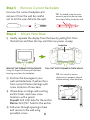
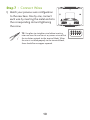
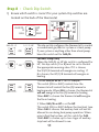
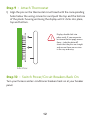
Quick Start &
Setup Guide
Thank You
Congratulations and thank you for purchasing
your new Venstar ColorTouch Wi-Fi thermostat.
This guide is intended to help you install and
setup the basic features of the ColorTouch
Thermostat. For a full owners manual and
installation guide, visit venstar.com. There you
will also find installation and setup videos along
with videos highlighting many features of the
ColorTouch thermostat. The videos can be
found in the Venstar TV video series area.
1
Compatibility
Venstar ColorTouch® Wi-Fi Thermostat is designed to work with 24V
systems requiring both the R & C wires. This includes gas, electric, oil,
forced air, variable speed, heat pump and radiant heat. It can control:
•Heating: one, two and three stages (W1, W2, W3)
•Cooling: one and two stages (Y1, Y2)
•Heat pump: with auxiliary and emergency heat (Y, W1, O/B)
•Fan (G)
•Power (C, R)
•Humidifier or dehumidifier (HUM, DEHUM)
•Dual fuel systems (heat pump with furnace)
•Whole-home humidifiers and dehumidifiers
Thermostat
W1/O/B
Y2
Y1
W2
W3/AUX
Contents
SENSOR
Thermostat
Base
Drywall Anchors
and Screws
This Quick Start
Manual
Necessary Tools
Level
WiFi Network
& Password
Screw Driver
Pencil
2
Pliers
Hammer or Drill
(3/16" or 7/32" drill bits)
Step 1 - Power Off Current System
1) Go to your home’s circuit breaker panel
and switch the furnace and air conditioner
breakers off.
2) To confirm power is off, adjust the temperature on your current thermostat.
If the system does not respond
accordingly, power has probably been
successfully shut off. WARNING: Failure to follow this step can result in personal
injury and/or death from shock and electrocution. Step 2 - Remove Faceplate
Remove the faceplate of current system. Most faceplates snap-off or
feature small screws that will need to be removed.
Wall
Side View
Thermostat
WARNING: If you see large thick
electrical wires, wire nuts, or if your
system is labeled 120V or 240V DO
NOT PROCEED. THIS THERMOSTAT
IS NOT COMPATIBLE WITH THESE
SYSTEMS
WARNING: Failure to follow this step
can result in personal injury and/or death from shock and electrocution.
3
Step 3 - Before you go any further
Determine what your existing wiring and equipment situation is
before you disconnect any wires. If you are unsure of what type of
system you have, you may need to seek professional support.
A. If you have a Heating only system without Air Conditioning, the
Venstar ColorTouch thermostat will require 3 wires. These 3 wires
are: R (24Vac), C (24Vac) and W (Heat). Most Heating only systems
use very simple thermostats that only require 2 wires the R (24Vac)
and W (Heat). The ColorTouch thermostat requires 3 wires to the
thermostat. In this case an Add-A-Wire accessory will not work
and it will be necessary to install another wire for the C (24Vac)
connection.
B. If you have a single stage fossil fuel heater with air conditioning,
the Venstar ColorTouch will require 5 wires for independent fan
control. They are R (24Vac), C (24Vac), W (Heat), Y (Cooling), and G
(Fan). You may connect only 4 wires, as instructed below, to the
ColorTouch but will give up independent fan control. The fan will
still operate with a Heating or Cooling demand.
• If there are only 4 wires present that are connected to the existing
thermostat, there are at least 3 options available to connect the
Venstar ColorTouch thermostat, they are:
1. Use the 4 wires as instructed below and note that the fan will
only operate with a Heating or Cooling demand.
2. Pull new thermostat wire from the HVAC equipment to the
thermostat so that there are at least 5 wires available.
3. Purchase and install a Venstar Add-A-Wire accessory
(ACC-0410).
4
C. If you have a multi stage HVAC system comprised of a fossil fuel
heater with air conditioning the Venstar ColorTouch will require
the 5 wires mentioned above (R, C, W, Y, and G) plus an additional
wire for each additional stage of Heating or Cooling. You may
reduce the 5 wire requirement to 4 if you give up independent fan
control, or use the optional accessory; Add-A-Wire.
D. If you have a heat pump without aux heat the Venstar ColorTouch
will require 5 wires: R (24Vac), C (24Vac), W1/O/B (reversing valve),
Y (1st stage compressor), and G (fan). If there are only 4 wires
present that are connected to the existing thermostat, there are
at least 3 options available to connect the Venstar ColorTouch
thermostat, they are:
1. Use the 4 wires as instructed below and note that the fan will
only operate with a Heating or Cooling demand.
2. Pull new thermostat wire from the HVAC equipment to the
thermostat so that there are at least 5 wires available.
3. Purchase and install a Venstar Add-A-Wire accessory (ACC-0410).
E. If you have a heat pump with aux heat the Venstar ColorTouch will
require 6 wires: R (24Vac), C (24Vac), W1/O/B (reversing valve), Y (1st
stage compressor), W2 (Aux Heat) and G (fan). If there are only 5
wires present that are connected to the existing thermostat, there
are at least 3 options available to connect the Venstar ColorTouch
thermostat, they are:
1. Use the 5 wires as instructed below and note that the fan will
only operate with a Heating or Cooling demand.
2. Pull new thermostat wire from the HVAC equipment to the
thermostat so that there are at least 6 wires available.
3. Purchase and install a Venstar Add-A-Wire accessory (ACC-0410).
5
MAKING 4 WIRES WORK when 5 are required
(without the optional Add-A-Wire accessory)
• If you have an all-electric heat system with air conditioning, this
method is not an option. You must either pull new wire or use the
optional Add-A-Wire accessory (ACC-0410).
• If you have a single stage fossil fuel heater with air conditioning,
and you would like install the Venstar ColorTouch using only 4 wires,
follow the directions below. You will need a screwdriver along with a
3” or 4” long piece of thermostat wire to use as a jumper.
1. Make sure the power is off as step 1 on page 4 instructs you.
2. Follow step 4 on page 9 “Label and Disconnect Wires” at the
thermostat. Please note the color and the corresponding wire
designator with each color. An example is the R wire is red and the
W wire is white and so on. You will need this for the next step at
the HVAC equipment.
3. At the equipment end of the thermostat wires, locate the
terminals that the wires are attached to.
A. Remove the “G wire” from the terminal marked G.
B. Place the “G wire” on terminal C.
C. Place one end of the jumper on terminal G.
D. Place the other end of the jumper on terminal Y. Please note that there will be more than 1 wire on terminal Y.
4. Connect the wires to the terminals on the ColorTouch backplate
taking care to make sure that each wire from the HVAC equipment
is connected to the same terminal designation on the ColorTouch
backplate. For example: the “C wire” from the HVAC equipment
should be connected to the “C” terminal of the thermostat. The
“R” wire on the equipment terminal should be connected to the
“R” terminal on the ColorTouch backplate, and so on.
6
MAKING 5 WIRES WORK when 6 are required
(without the optional Add-A-Wire accessory)
• If you have an all-electric heat system with air conditioning, this
method is not an option. You must either pull new wire or use the
optional Add-A-Wire accessory (ACC-0410).
• If you have a multi stage system that requires 6 wires, and you
would like install the Venstar ColorTouch using only 5 wires, follow
the directions below. You will need a screwdriver along with a 3” or
4” long piece of thermostat wire to use as a jumper.
1. Make sure the power is off as step 1 on page 6 instructs you.
2. Follow step 4 on page 9 “Label and Disconnect Wires” at the
thermostat. Please note the color and the corresponding wire
designator with each color. An example is the R wire is red and the
W wire is white and so on. You will need this for the next step at
the HVAC equipment.
3. At the equipment end of the thermostat wires, locate the
terminals that the wires are attached to.
A. Remove the “G wire” from the terminal marked G.
B. Place the “G wire” on terminal C.
C. Place one end of the jumper on terminal G.
D. Place the other end of the jumper on terminal Y.
Please note that there will be more than 1 wire on terminal Y.
E. Connect the wires to the terminals on the ColorTouch
backplate taking care to make sure that each wire from the
HVAC equipment is connected to the same terminal on the
ColorTouch backplate. For example: the “C wire” from the
HVAC equipment is connected to the “C” terminal of the
thermostat and so on.
7
Step 4 - Label & Disconnect Wires
TIP: Before disconnecting any wires,
take a photo of your current wire
configuration with your mobile device.
1) One by one, apply a label
designated to each wire
you disconnect from
your current thermostat.
Wire from the old thermostat
Function terminal marked
Install on the
new thermostat
connector marked
G or F
Fan
G
Y1, Y
Cooling/Compressor
Y1
W1, W
Heating
W1/0/B
Rh, R, M, Vr, A
Power
C
Wire
Color
R
Common
C
O/B
Rev. Valve
W1/O/B*
W2
2nd Stage Heat
W2
Y2
2nd Stage Cooling
Y2
W3
3rd Stage Heat
W3
OUT - Outdoor Sensor
SENSOR
OUT +
Outdoor Sensor
SENSOR
* O/B is used if your system is a Heat Pump.
NOTE: If the terminal designations on your old thermostat do not match
those on the new thermostat refer to sample wiring diagrams in the
full user’s manual at venstar.com in the support section.
8
Step 5 - Remove Current Backplate
Unscrew the current backplate and
remove it from the wall. Be careful
not to let the wires fall into the wall.
TIP: If needed, wrap the wires
around a pencil or pen to keep
them from falling inside the wall.
Step 6 - Mount New Base
1) Gently separate the display from the base by pulling first from
the bottom and then the top until the two pieces unsnap.
Backplate
PULL OUT WITH THUMBS IN THESE AREAS.
W1/O/B
Y2
Y1
TIP: Use a level to ensure
thermostat is properly aligned
before marking screw locations.
W2
2) Position the base against your
wall, and determine if wall anchors
from current thermostat align with
screw locations of new base.
3) If base does not align with existing
anchor holes, mark new screw
locations with a pencil.
Drywall: Drill 3/16" hole for the anchor
Plaster: Drill 7/32” hole for the anchor
4) Pull wires through opening in base
and secure to the wall using
provided screws.
9
W3/AUX
REMOVE THE THERMOSTAT BACKPLATE:
Using the Finger Pull Areas, pull the front
housing away from the backplate.
SENSOR
Wi
F
& P i Net
ass wo
wo rk
rd
Scr
ew
D
rive
r
Pen
cil
(3/ Ham
16" me
or r o
7/3 r D
2" d rill
rill
bit
s)
W1/O/B
Y2
Y1
W2
TIP: Use pliers to straighten wire before inserting
into new base. Be sure to cut any excess wire so that
the insulation extends to the terminal block. When
the wire is installed properly to the terminal block,
there should be no copper exposed.
Lev
el
Plie
rs
Thi
sQ
Ma uick S
nua tar
t
l
1) Match your previous wire configuration
to the new base. One by one, connect
each wire by inserting the metal end into
the corresponding slot and tightening
the screw.
W3/AUX
Step 7 - Connect Wires
10
SENSOR
Step 8 - Check Dip Switch
1
2
ON
GAS/EL
O
GAS
3
1) Ensure which switch is correct for your system. Dip switches are
located on the back of the thermostat
HP
B
ELEC
SENSOR
1
ON
2
OR
2
2
3
1
B
1
OR
O
ON
3
2
1
ON
GAS/ ELEC
OR
ON
3
3
2
B
1
ON
O
2
3
GAS/EL HP
1
ON
3
GAS/EL HP
GAS/ELEC
This dip switch configures the thermostat to control
a conventional gas/electric system or a heat pump. If your system is anything other than a heat pump,
leave this switch set for GAS/EL.
For Heat Pump Only
When the GAS/EL or HP dip switch is configured for
HP, this dip switch (O or B) must be set to control
the appropriate reversing valve. If O is chosen,
the W1/O/B terminal will energize in cooling. If
B is chosen, the W1/O/B terminal will energize in
heating.
1. When GAS/EL or HP is set for GAS/EL:
This switch (GAS or ELEC) controls how the
thermostat will control the Fan (G) terminal in
heating mode. When GAS is chosen, the thermostat
will not energize the Fan (G) terminal in heating. When ELEC is chosen the thermostat will energize
the fan in heating.
2. When GAS/EL or HP is set for HP:
This switch (GAS or ELEC) defines the Aux Heat type. When GAS is chosen, the auxiliary heat will not be
allowed to run during heat pump operation. When
using a Dual Fuel system, set this switch for GAS.
When ELEC is chosen, up to two stages of auxiliary
strip heat will be allowed to run.
11
Step 9 - Attach Thermostat
1) Align the pins on the thermostat circuit board with the corresponding
holes below the wiring connectors and push the top and the bottom
of the plastic housing enclosing the display until it clicks into place,
top and bottom.
Display should click into
place easily. If you encounter
resistance do not apply excess
force – take the plate off,
check that the pins are straight
and ensure there are no wires
in the way and retry.
Side View
Step 10 - Switch Power/Circuit Breakers Back On
Turn your furnace and air conditioner breakers back on at your breaker
panel.
12
Step 11 - Set Up Wi-Fi Connection
Overview
At minimum, the first 3 tasks below must be completed to access your
thermostat remotely from a browser. The 4th step is optional (highly
recommended) and only is needed to access your thermostat(s) from
a mobile device.
These steps are:
1. Successful connection to a local Wi-Fi Access Point with internet
access.
2. Confirm receipt of a Skyport generated verification email (this only
occurs once during the Skyport account setup).
3. A 6-digit code obtained from the thermostat is successfully
entered into a Skyport account.
4. Successfully download and install the Venstar Skyport app on your
mobile device(s).
Your thermostat operates on the 2.4 Ghz, Wi-Fi b/g/n band.
13
Quick Start - Connect to Wi-Fi (from initial start up)
When power is connected to the thermostat and it has not been
configured to connect to a Wi-Fi Access Point, the following
message appears:
Wi-Fi Set Up
No Wi-Fi access points are
configured for your thermostat.
Would you like to set up one now?
YES
YES
NO
Press YES
Select the access point you wish to connect to from the list.
Enter the password for the Wi-Fi Access Point and press NEXT.
Select automatic setup and press NEXT.
When finished, a dialog box will appear confirming the successful
connection to the local Wi-Fi Access Point.
Select OK, then the Wi-Fi status page will appear. Upon closing
of the Wi-Fi status page, you will be asked to join the thermostat
to a Skyport account.
Select YES and follow the onscreen instructions to create a new
Skyport account or to add the thermostat to an existing account.
14
Quick Start - Connect to Wi-Fi (from menus)
72
MENU
Press MENU
72
Press DOWN
Press Wi-Fi
• Wi Fi Setup
Press Wi-Fi Setup
Select the access point from the list that you want to
connect to.
Enter the password for the Wi-Fi Access Point and press NEXT.
Select automatic setup and press NEXT.
When finished, a dialog box will appear confirming the successful
connection to the local Wi-Fi Access Point.
Select OK, then the Wi-Fi status page will appear. Upon closing
of the Wi-Fi status page, you will be asked to join the thermostat
to a Skyport account.
Select YES and follow the onscreen instructions to create a new
Skyport account or to add the thermostat to an existing account.
15
Quick Start - Connect to Skyport (from menus)
Although there is more than one way to create a Skyport account, the
steps below illustrate creation from a browser.
If the thermostat is connected to the local Wi-Fi Access Point, but not
yet joined to a Skyport account, you may join the thermostat to an
account by doing the following:
Select MENU from the thermostat’s home screen.
Scroll down
Select Skyport
Select Skyport Account and follow the onscreen instructions.
• Skyport Account
1. Open your browser to: http://venstar.skyportcloud.com
2. Select “Create account now”
4 Create Account Now
3. Follow on screen instructions to create an account and add a
thermostat to the Skyport account.
16
Troubleshooting
Use the following troubleshooting guide to diagnose common
problems. If you are still having problems or are unsure please
visit www.venstar.com/thermostats or e-mail customer service at
[email protected]
Problem
Possible Cause
Solution
The air conditioning does
not attempt to turn on.
The compressor timer
lockout may prevent the air
conditioner from turning on
for a period of time.
Adjust the
Compressor Min. Off TIme
to “None”.
The cooling setpoint is set
too high.
Lower the cooling setpoint
or lower the cooling
setpoint limit.
You may have selected Free
Cooling in settings.
If you don’t have a damper,
and special duct work
installed, turn off this
feature in settings.
The display is blank.
Lack of proper power.
Make sure the power
is on to the furnace
and that you have a 24 vac
between R&C.
The heating does not
attempt to turn on.
The heating setpoint is set
too low.
Raise the
heating setpoint or raise
the heating setpoint limit.
When using a residential
heat pump the heat comes
on instead of the air
conditioning.
The thermostat reversing
valve dip switch is set
incorrectly.
Set the reversing valve dip
switch to the opposite
position.
When calling for air
conditioning both the heat
and cool come on.
The thermostat equipment
dip switch is configured for
“HP” and the HVAC unit is a
gas/electric.
Set the equipment dip
switch for “gas”.
17
Warranty
One-Year Warranty - This Product is warranted to be free from defects in material and
workmanship. If it appears within one year from the date of original installation, whether
or not actual use begins on that date, that the product does not meet this warranty, a new
or remanufactured part, at the manufacturer’s sole option to replace any defective part, will
be provided without charge for the part itself provided the defective part is returned to the
distributor through a qualified servicing dealer.
THIS WARRANTY DOES NOT INCLUDE LABOR OR OTHER COSTS incurred for diagnosing,
repairing, removing, installing, shipping, servicing or handling of either defective parts or
replacement parts. Such costs may be covered by a separate warranty provided by the installer.
THIS WARRANTY APPLIES ONLY TO PRODUCTS IN THEIR ORIGINAL INSTALLATION LOCATION
AND BECOMES VOID UPON REINSTALLATION.
LIMITATIONS OF WARRANTIES – ALL IMPLIED WARRANTIES (INCLUDING IMPLIED WARRANTIES
OF FITNESS FOR A PARTICULAR PURPOSE AND MERCHANTABILITY) ARE HEREBY LIMITED IN
DURATION TO THE PERIOD FOR WHICH THE LIMITED WARRANTY IS GIVEN. SOME STATES DO
NOT ALLOW LIMITATIONS ON HOW LONG AN IMPLIED WARRANTY LASTS, SO THE ABOVE MAY
NOT APPLY TO YOU. THE EXPRESSED WARRANTIES MADE IN THIS WARRANTY ARE EXCLUSIVE
AND MAY NOT BE ALTERED, ENLARGED, OR CHANGED BY ANY DISTRIBUTOR, DEALER, OR
OTHER PERSON WHATSOEVER.
ALL WORK UNDER THE TERMS OF THIS WARRANTY SHALL BE PERFORMED DURING NORMAL
WORKING HOURS. ALL REPLACEMENT PARTS, WHETHER NEW OR REMANUFACTURED,
ASSUME AS THEIR WARRANTY PERIOD ONLY THE REMAINING TIME PERIOD OF THIS
WARRANTY.
THE MANUFACTURER WILL NOT BE RESPONSIBLE FOR:
1.Normal maintenance as outlined in the installation and servicing instructions or owner’s
manual, including filter cleaning and/or replacement and lubrication.
2.Damage or repairs required as a consequence of faulty installation, misapplication, abuse,
improper servicing, unauthorized alteration or improper operation.
3.Failure to start due to voltage conditions, blown fuses, open circuit breakers or other damages
due to the inadequacy or interruption of electrical service.
4.Damage as a result of floods, winds, fires, lightning, accidents, corrosive environments or
other conditions beyond the control of the Manufacturer.
5.Parts not supplied or designated by the Manufacturer, or damages resulting from their use.
6.Manufacturer products installed outside the continental U.S.A., Alaska, Hawaii, and Canada.
7. Electricity or fuel costs or increases in electricity or fuel costs for any reason whatsoever
including additional or unusual use of supplemental electric heat.
8.ANY SPECIAL INDIRECT OR CONSEQUENTIAL PROPERTY OR COMMERCIAL DAMAGE
OF ANY NATURE WHATSOEVER. Some states do not allow the exclusion of incidental or
consequential damages, so the above may not apply to you.
This warranty gives you specific legal rights and you may also have other rights which may vary
from state to state.
18
FCC Compliance Statement
This equipment has been tested and found to comply with the limits for an
intentional radiator, pursuant to Part 15, subpart C of the FCC rules. These limits
are designed to provide reasonable protection against harmful interference
in a residential installation. This equipment generates, uses and can radiate
radio frequency energy and, if not installed and used in accordance with
the instructions, may cause harmful interference in radio communications.
However, there is no guarantee that the interference will not occur in a
particular installation. If this equipment does cause harmful interference
to radio or television reception, which can be determined by turning the
equipment off and on, the user is encouraged to try to correct the interference
by one or more of the following measures:
• Reorient or relocate the receiving antenna.
• Increase the separation between the equipment and receiver.
• Connect the equipment into an outlet on a circuit different from that of the
receiver.
• Consult the dealer or an experienced radio or TV technician for help.
Notice: Only peripherals complying with FCC limits may be attached to this
equipment. Operation with noncompliant peripherals or peripherals not
recommended by Venstar, is likely to result in interference to radio and TV
reception. Changes or modifications to the product, not expressly approved by
Venstar could void the user’s authority to operate the equipment.
FCC - INDOOR Mobile Radio Information:
To comply with FCC/IC RF exposure limits for general population / uncontrolled
exposure, the antenna(s) used for this transmitter must be installed to provide
a separation distance of at least 20 cm from all persons and must not be colocated or operating in conjunction with any other antenna or transmitter.
This Device complies with Industry Canada License-exempt RSS standard(s).
Operation is subject to the following two conditions: 1) this device may not
cause interference, and 2) this device must accept any interference, including
interference that may cause undesired operation of the device.
Under Industry Canada regulations, this radio transmitter may only operate
using an antenna of a type and maximum (or lesser) gain approved for the
transmitter by Industry Canada. To reduce potential radio interference to other
users, the antenna type and its gain should be so chosen that the equivalent
isotropically radiated power (e.i.r.p.) is not more than that necessary for
successful communication.
19
(continued)
Cet appareil est conforme avec Industrie Canada, exempts de licence standard
RSS(s). Son fonctionnement est soumis aux deux conditions suivantes: 1) ce
dispositif ne doit pas causer d’interférences, et 2) ce dispositif doit accepter
toute interférence, y compris les interférences qui peuvent causer un mauvais
fonctionnement de l’appareil.
En vertu des règlements d’Industrie Canada, cet émetteur de radio ne peut
fonctionner en utilisant une antenne d’un type et maximale (ou moins) Gain
approuvé pour l’émetteur par Industrie Canada. Pour réduire les interférences
radio potentielles aux autres utilisateurs, le type d’antenne et son gain doivent
être choisis afin que la puissance isotrope rayonnée équivalente (PIRE) ne est
pas plus de ce qui est nécessaire pour une communication réussie.
We, Venstar, declare under our sole responsibility that the device to which
this declaration relates: Complies with Part 15 of the FCC Rules. Operation is
subject to the following two conditions: (1) this device may not cause harmful
interference, and (2) this device must accept any interference received,
including interference that may cause undesired operation.
FCC ID: MUH-SKYPORT2
IC ID: 12547A-SKYPORT2
These numbers can be located on the inside of the
thermostat backplate, in the upper right corner.
MUH-SKYPORT2
20
Patents Issued & Pending
Printed on recycled paper.
P/N 88-1094
Rev. 1
02/15