1
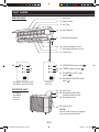
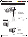
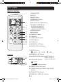
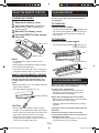
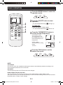
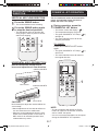
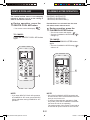
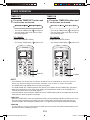
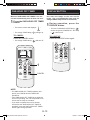
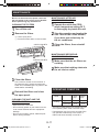
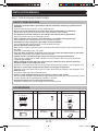
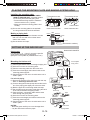
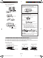
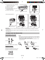
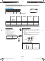
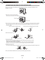
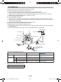
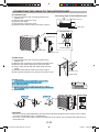
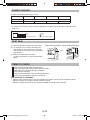
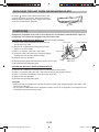
OPERATION MANUAL INSTALLATION MANUAL AH-PN10, 10GY AH-L10 AH-PN13, 13GY AH-L13 AH-PN19, AH-PN24 INDOOR UNIT AH-PN10 AH-PN10-GY AH-PN13 AH-PN13-GY AH-PN19 AH-PN24 AH-L10 AH-L13 OUTDOOR UNIT AU-PN10 AU-PN10 AU-PN13 AU-PN13 AU-PN19 AU-PN24 AU-L10 AU-L13 CONTENTS Page IMPORTANT SAFETY INSTRUCTIONS 1 PART NAMES 2 USING THE REMOTE CONTROL 5 AUXILIARY MODE 5 TIPS ON SAVING ENERGY 5 BASIC OPERATION 6 ADJUSTING THE AIR FLOW DIRECTION 7 POWERFUL JET OPERATION 7 GENTLE COOL AIR 8 PLASMACLUSTER OPERATION 8 TIMER OPERATION 9 ONE-HOUR OFF TIMER 10 DISPLAY BUTTON 10 MAINTENANCE 11 OPERATING CONDITION 11 BEFORE CALLING FOR SERVICE 12 INSTALLATION MANUAL 13 Thank you for purchasing a SHARP air conditioner. Please read this manual carefully before operating the product OM_AH-PN10 13GY_EN.indd 1 12/22/11 6:30:07 PM OM_AH-PN10 13GY_EN.indd 2 12/22/11 6:30:09 PM ENGLISH Please read this manual carefully before using the product. This manual should be kept in a safe place for handy reference. CAUTIONS IMPORTANT SAFETY INSTRUCTIONS WARNINGS • Do not pull or deform the power supply cord. Pulling and misuse of the power supply cord can result in damage to the unit and cause electrical shock. • Be careful not to expose your body directly to the outlet air for a long time. It may affect your physical conditions. • When using the air conditioner for infants, children, elderly, bedridden, or disabled people make sure the room temperature is suitable for those in the room. • Never insert objects into the unit. Inserting objects can result in injury due to the high speed rotation of internal fans. • Ground the air conditioner without fail. Do not connect the grounding wire to gas pipe, water pipe, lightning rod or telephone grounding wire. Incomplete grounding may cause electric shock. • If anything is abnormal with the air conditioner (ex. a burning smell), stop the operation immediately and turn the circuit breaker OFF. • The appliance shall be installed in accordance with national wiring regulations. Improper cable connection can cause the power supply cord, plug and the electrical outlet to overheat and cause fire. • If the supply cord is damaged, it must be replaced by the manufacturer or its service agent or a similarly qualified person in order to avoid a hazard. Use only the manufacture specified power cord for replacement. • Do not splash or pour water directly on the unit. Water can cause electrical shock or equipment damage. • Do not attempt to install/remove/repair the unit by yourself. Incorrect work will cause electric shock, water leak, fire etc. Consult your dealer or other qualified service personnel for the installation/removal/repair of the unit. ENG- • Open a window or door periodically to ventilate the room, especially when using gas appliances. Insufficient ventilation may cause oxygen shortage. • Do not operate the buttons with wet hand. It may cause electric shock. • For safety, turn the circuit breaker off when not using the unit for an extended period of time. • Check the outdoor unit mounting rack periodically for wear and to make sure it is firmly in place. • Do not put anything on the outdoor unit nor step on it. The object or the person may fall down or drop, causing injury. • This unit is designed for residential use. Do not use for other applications such as in a kennel or greenhouse to raise animals or grow plants. • Do not place a vessel with water on the unit. If water penetrates into the unit, electrical insulations may deteriorate and cause electric shock. • Do not block the air inlets nor outlets of the unit. It may cause insufficient performance or troubles. • Be sure to stop the operation and turn the circuit breaker off before performing any maintenance or cleaning. A fan is rotating inside the unit and you may get injured. • This appliance is not intended for use by young children or infirm persons without supervision. Young children should be supervised to ensure that they do not play with the appliance. • Make sure to connect the air conditioner to power supply of the rated voltage and frequency. Use of a power supply with improper voltage and frequency can result in equipment damage and possible fire. • Do not install the unit in a place where inflammable gas may leak. It may cause fire. Install the unit in a place with minimal dust, fumes and moisture in the air. • Arrange the drain hose to ensure smooth drainage. Insufficient drainage may cause wetting of the room, furniture etc. • Make sure a leak breaker or a circuit breaker is installed, depending on the installation location, to avoid electrical shock. E-1 OM_AH-PN10 13GY_EN.indd Sec1:1 12/22/11 6:30:09 PM PART NAMES INDOOR UNIT 12 9 1 Inlet (Air) 2 3 2 Open Panel 4 4 AUX Button 5 5 Receiver Window 6 6 Vertical Airflow Louvre 7 8 7 Horizontal Airflow Louvre 3 Air Filter 8 Outlet (Air) 9 9 OPERATION Lamp (red ) 10 10 TIMER Lamp (orange ) 11 11 POWERFUL JET Lamp (green ) 10 11 AH-PN10, AH-PN10-GY AH-PN13, AH-PN13-GY 1 12 PLASMACLUSTER Lamp (blue ) AH-L10 AH-L13 OUTDOOR UNIT AU-PN10 AU-PN13 AU-L10 AU-L13 13 13 Inlet (Air) 14 14 Refrigerant Pipe and Interconnecting Cord 15 Drainage Hose 15 16 16 Outlet (Air) NOTE: Actual units might vary slightly from those shown above. E-2 OM_AH-PN10 13GY_EN.indd Sec1:2 12/22/11 6:30:10 PM INDOOR UNIT 1 1 Inlet (Air) 2 3 2 Open Panel 4 4 AUX Button 5 5 Receiver Window 6 6 Power Supply Cord 7 8 9 7 Vertical Airflow Louvre 3 Air Filter ENG- 8 Horizontal Airflow Louvre 9 Outlet (Air) 10 10 PLASMACLUSTER Lamp (blue ) 11 12 11 OPERATION Lamp (red OUTDOOR UNIT AU-PN19 14 15 16 ) ) 13 12 TIMER Lamp (orange 13 POWERFUL JET Lamp AH-PN19, AH-PN24 (blue ) 17 AU-PN24 14 15 16 14 Inlet (Air) 15 Refrigerant Pipe and Interconnecting Cord 16 Drainage Hose 17 Outlet (Air) 17 NOTE: Actual units might vary slightly from those shown above. E-3 OM_AH-PN10 13GY_EN.indd Sec1:3 12/22/11 6:30:11 PM PART NAMES REMOTE CONTROL 1 1 TRANSMITTER 2 DISPLAY 3 ON/OFF Button 4 THERMOSTAT Button 2 3 4 5 6 7 8 9 10 11 12 13 14 15 16 5 DISPLAY Button 6 ONE-HOUR OFF TIMER Button 7 PLASMACLUSTER Button (AH-PN10, AH-PN10-GY AH-PN13, AH-PN13-GY AH-PN19, AH-PN24 ONLY) 8 TIMER ON Button 9 MODE Button 10 TIMER OFF Button 11 FAN Button 12 TIMER CANCEL Button 13 SWING Button 14 Reset Button 15 POWERFUL JET Button 16 GENTLE COOL AIR Button 17 MODE Symbols : AUTO 21 22 19 20 : DRY 18 POWERFUL JET Symbol DISPLAY 17 18 : COOL 19 PLASMACLUSTER Symbol (AH-PN10, AH-PN10-GY AH-PN13, AH-PN13-GY AH-PN19, AH-PN24 ONLY) 20 FAN SPEED Symbols : AUTO 23 24 : Manual setting 21 GENTLE COOL AIR Symbol 22 TEMPERATURE AND TIMER COUNT DOWN Indicator 23 TRANSMITTING Symbol 24 TIMER ON / TIMER OFF Indicator E-4 OM_AH-PN10 13GY_EN.indd Sec1:4 12/22/11 6:30:13 PM AUXILIARY MODE USING THE REMOTE CONTROL LOADING BATTERIES Use this mode when the remote control is not available. the battery cover. 1 Remove Insert two batteries. (AAA(R03)) 2 + the battery cover. 3 Reinstall Press the RESET button using a 4 thin stick. TO TURN ON Press the AUX button. Make sure the ( ) and ( ) polarities are correctly aligned. • The fan speed and temperature setting are set to AUTO. ENG- • The red OPERATION lamp ( ) will light and the unit will start operating in the AUTO mode. TO TURN OFF Press the AUX button again. Battery cover • The red OPERATION lamp ( ) will turn off. 9,000/12,000 BTU AUX RESET button NOTE: • The battery life is approximately 1 year in normal use. • When replacing the batteries, always change both and use the same type. • If you will not be using the unit for a long time, remove the batteries from the remote control. 18,000/24,000 BTU AUX HOW TO USE THE REMOTE CONTROL Point the remote control towards the receiver window and press the desired button. The unit generates a beep when it receives the signal. • Make sure nothing, such as curtains, block the signal receiver window. • The signal effective distance is 7 m. TIPS ON SAVING ENERGY Below are some simple ways to save energy when you use your air conditioner. Set the proper temperature • Setting the temperature lower than necessary during cooling operation will result in increased power consumption. Receiver window Block direct sunlight and prevent drafts • Blocking direct sunlight during cooling operation will reduce power consumption. • Close the windows and doors during cooling operation. • Do not expose the receiver window to direct sunlight. This may adversely affect its operation. • Use of certain fluorescent lamp in the same room may interfere with transmission of the signal. • Do not leave the remote control in direct sunlight or near a heater. Protect the remote control from moisture and shock. Keep filter clean to ensure the most efficient operation 7m CAUTION: Disconnect the power cord or turn off the circuit breaker when the unit is not used for an extended period of time • The indoor unit still consumes a small amount of power when it is not operating. E-5 OM_AH-PN10 13GY_EN.indd Sec1:5 12/22/11 6:30:14 PM BASIC OPERATION Press the MODE button to select the 1 operation mode. AUTO 2 3 1 4 COOL DRY Press the ON/OFF button to start 2 operation. • The red OPERATION lamp ( ) will light up. TO TURN OFF Press the ON/OFF button again. • The red OPERATION lamp ( ) will turn off. Press the THERMOSTAT button to 3 set the desired temperature. (AUTO/DRY mode) The temperature can be changed up to ±2 °C the automatically set of temperature. (COOL mode) The temperature setting range: 16-30°C. Press the FAN button to set the 4 desired fan speed. AUTO SOFT LOW HIGH NOTE: AUTO MODE In the AUTO mode, the temperature setting and mode are automatically selected according to the room temperature when the unit is turned on. DRY MODE The fan speed is preset to AUTO and cannot be changed. WHEN POWER FAILURE OCCURS This air conditioner has a memory function to store settings when a power failure occurs. After power recovery, the unit will automatically re-start in the same settings which were active before the power failure, except for timer settings. E-6 OM_AH-PN10 13GY_EN.indd Sec1:6 12/22/11 6:30:16 PM ADJUSTING THE AIR FLOW DIRECTION POWERFUL JET OPERATION The air conditioner works at the maximum power and optimum louvre direction to makes the room cool rapidly. VERTICAL AIR FLOW DIRECTION 1 Press the SWING button. the SWING button again 2 toPress stop the desired position. • The vertical airflow louvre will swing. During operation, press the JET button. 1 POWERFUL • The green POWERFUL JET lamp ( will light up. • The vertical airflow louvre will be set obliquely downward. 1 2 ) ENG- • The remote control will display “ ”. • The temperature display will go off. • The adjustment range is narrower the swing range in order to prevent condensation from dripping. TO CANCEL Press the POWERFUL JET button again. • The green POWERFUL JET lamp ( ) will turn off. • The vertical airflow louvre will return to the original direction. HORIZONTAL AIR FLOW DIRECTION Hold the horizontal airflow louvre levers and adjust the air flow direction. 9,000/12,000 BTU Louvre lever CAUTION: 1 18,000/24,000 BTU Louvre lever Never attempt to adjust the vertical airflow louvre manually. • Manual adjustment of the vertical airflow louvre can cause the unit to malfunction. • When the vertical adjustment louvre is positioned at the lowest position in the COOL or DRY mode for an extended period of time, condensation may result. NOTE: • The air conditioner will operate at “Extra HIGH” fan speed for 30 minutes, and then shift to “HIGH” fan speed. • You can not set the temperature or fan speed during the POWERFUL JET operation. E-7 OM_AH-PN10 13GY_EN.indd Sec1:7 12/22/11 6:30:17 PM GENTLE COOL AIR PLASMACLUSTER OPERATION The vertical airflow louvre is set obliquely upward to deliver cool air to the ceiling in order to avoid direct airflow. (AH-PN10, AH-PN10-GY AH-PN13, AH-PN13-GY AH-PN19, AH-PN24 ONLY) During operation, press the COOL AIR button. 1 GENTLE Plasmacluster ions released into the room will reduce some airborne mold. • The remote control will display “ ”. During operation, press the 1 PLASMACLUSTER button. • The remote control will display “ ”. • The blue PLASMACLUSTER lamp ( will light up. TO CANCEL Press the GENTLE COOL AIR button again. ) TO CANCEL Press the PLASMACLUSTER button again. • The blue PLASMACLUSTER lamp ( will turn off. ) 1 1 NOTE: NOTE: • Use of the PLASMACLUSTER operation will be memorized, and it will be activated the next time you turn on the unit. • To perform Plasmacluster operation in FAN only mode, press the PLASMACLUSTER button when the unit is not operating. The mode symbol of the remote control will go off and the fan speed cannot be set to AUTO. • If you want GENTLE COOL AIR operation in POWERFUL JET mode, press GENTLE COOL AIR button during POWERFUL JET operation. E-8 OM_AH-PN10 13GY_EN.indd Sec1:8 12/22/11 6:30:18 PM TIMER OPERATION TIMER ON TIMER OFF the TIMER ON button and Press the TIMER OFF button and 1 Press set the time as desired. 1 set the time as desired. 0.5h 1.0h 1.5h 10h 11h 0.5h 12h 1.0h 1.5h 10h 11h 12h • The orange TIMER lamp ( ) will light up. • The time setting will count down to show the remaining time. TO CANCEL TO CANCEL Press the CANCEL button. Press the CANCEL button. • The orange TIMER lamp ( ENG- • The orange TIMER lamp ( ) will light up. • The time setting will count down to show the remaining time. ) will turn off. • The orange TIMER lamp ( ) will turn off. 1 1 CANCEL CANCEL NOTE: • Timer duration can be set from a minimum of half an hour to a maximum of 12 hours. Up to 9.5 hours, you can set in half-hour increments, and from 10 to 12 hours, in 1-hour increments. • The TIMER OFF and TIMER ON can not be set together. • The ONE-HOUR OFF TIMER operation has priority over TIMER ON and TIMER OFF operations. • When the temperature is set during timer setting, the temperature will show in the display for 5 seconds and then return to the timer display. • If a power failure occurs while the TIMER is set, the TIMER setting will be cancelled and will not be retrieved even after the power is restored. TIMER OFF • When the TIMER OFF is set, the temperature setting is automatically adjusted to prevent the room from becoming excessively cold while you sleep. (Auto Sleep function) One hour after the time operation begins, the temperature setting rises 1°C higher than the original temperature setting. TIMER ON • The unit will turn on prior to the set time to allow the room to reach the desired temperature by the programmed time. (Awaking function) E-9 OM_AH-PN10 13GY_EN.indd Sec1:9 12/22/11 6:30:20 PM ONE-HOUR OFF TIMER DISPLAY BUTTON When the ONE-HOUR OFF TIMER is set, the unit will automatically turn off after one hour. Press the ONE-HOUR OFF TIMER 1 button. • The remote control will displays “ • The orange TIMER lamp ( Use when the lamps on the unit are too bright. (The red OPERATION lamp and the orange TIMER lamp cannot be turned off.) During operation, press the 1 DISPLAY button. ”. • The blue PLASMACLUSTER lamp ( ) will light up. TO CANCEL TO LIGHT UP Press the CANCEL button. • The orange TIMER lamp ( ) and/or the green POWERFULL JET lamp ) will turn off. ( Press the DISPLAY button again. ) will turn off. 1 1 CANCEL NOTE: • The ONE-HOUR OFF TIMER operation has priority over TIMER ON and TIMER OFF operations. • If the ONE-HOUR OFF TIMER is set while the unit is not operating, the unit will operate for an hour at the formerly set condition. • If you wish to operate the unit for another hour before the ONE-HOUR OFF TIMER is activated, press the ONE-HOUR OFF TIMER button again during operation. E-10 OM_AH-PN10 13GY_EN.indd Sec1:10 12/22/11 6:30:21 PM MAINTENANCE MAINTENANCE AFTER AIR CONDITIONER SEASON Be sure to disconnect the power cord from the wall outlet or turn off the circuit breaker before performing any maintenance. the unit in the COOL 1 Operate mode, temperature setting 30˚C, CLEANING THE FILTERS 1 Turn off the unit. 2 Remove the filters. to thoroughly dry inside the unit. 1 Lift the open panel. 2 Pull the air filters down to remove them. ENG- the operation and unplug the 2 Stop unit. Turn off the circuit breaker, if you have one exclusively for the air conditioner. 9,000/12,000 BTU the filters, then reinstall 3 Clean them. MAINTENANCE BEFORE AIR CONDITIONER SEASON 18,000/24,000 BTU sure that the air filters are 1 Make not dirty. sure that nothing obstructs 2 Make the air inlet or outlet. 3 Clean the filters. Use a vacuum cleaner to remove dust. If the filters are dirty, wash them with warm water and a mild detergent. Dry filters in the shade before reinstalling. OPERATING CONDITION 4 Reinstall the filters and close the open panel. Indoor Temp. Outdoor Temp. Upper limit 32˚C 43˚C Lower limit 21˚C 21˚C Mode CLEANING THE UNIT AND THE REMOTE CONTROL • Wipe them with a soft cloth. • Do not directly splash or pour water on them. It can cause electrical shock or equipment damage. • Do not use hot water, thinner, abrasive powders or strong solvents. Cooling • The built-in safety device may prevent the unit from operating when used out of this range. • Condensation may form on the air outlet if the unit operates continuously in the COOL or DRY mode when humidity is over 80 %. E-11 OM_AH-PN10 13GY_EN.indd Sec1:11 12/22/11 6:30:22 PM BEFORE CALLING FOR SERVICE The following conditions do not denote equipment malfunctions Check the following points before calling for service. UNIT DOES NOT OPERATE The unit does not operate The unit will not operate if it is turned on immediately after it is turned off. The unit will not operate immediately after the mode is changed. This is to protect the unit. Wait 3 minutes before operating the unit. • Check if the circuit breaker has tripped or the fuse has blown. ODORS Carpet and furniture odors that entered into theunit may be sent out from the unit. CRACKING NOISE This sound is generated by the friction of the unit expanding or connecting due to a temperature change. SWISHING NOISE The soft, swishing noise is the sound of the refrigerant flowing inside the unit. MIST SEEN AT INDOOR AIR OUTLET In cooling operation, this is caused by the difference between the room air temperature and the air discharged. ODOR EMITTED FROM THE PLASMACLUSTER AIR OUTLET (AH-PN10, AH-PN10-GY AH-PN13, AH-PN13-GY AH-PN19, AH-PN24 ONLY) The unit does not cool effectively • Check the filters. If dirty, clean them. • Check the outdoor unit to make sure nothing is blocking the air inlet or outlet. • Check the thermostat is proper setting. • Make sure windows and doors are closed tightly. The unit does not receive the remote control signal • Check whether the remote control batteries have become old and weak. • Try to send the signal again with the remote control pointed properly towards the unit’s signal receiver window. • Check whether the remote control batteries are installed properly. Please call for service when OPERATION lamp, TIMER lamp and/or PLASMACLUSTER lamp on the unit blink. (AH-PN10, AH-PN10-GY AH-PN13, AH-PN13-GY AH-PN19, AH-PN24 ONLY) This is the smell of ozone generated from the Plasmacluster Ion generator. The ozone concentration is very small, posing no adverse effect on your health. The ozone discharged into the air rapidly decomposes, and its density in the room will not increase. A LOW BUZZING NOISE (AH-PN10, AH-PN10-GY AH-PN13, AH-PN13-GY AH-PN19, AH-PN24 ONLY) This is a sound of the unit generating Plasmacluster ions. E-12 OM_AH-PN10 13GY_EN.indd Sec1:12 12/22/11 6:30:23 PM INSTALLATION MANUAL SPLIT TYPE ROOM AIR CONDITIONER SAFETY PRECAUTIONS ENG- • Installation must be made in accordance with the installation manual by qualified service personnel. Incorrect work will cause electric shock, water leak, fire. • Be sure to use the attached accessories parts and specified parts for installation. Use of other parts will cause electric shock, water leak, fire, the unit falling. • The appliance shall be installed in accordance with national wiring regulations. Wrong connection can cause overheating or fire. • After installation has complete, check that there is no leakage of refrigerant gas. If the refrigerant gas contact with fire, it may generate toxic gas. • Ventilate the room if refrigerant gas leakes during installation. If the refrigerant gas contact with fire, it may generate toxic gas. • Use the specified electrical cable. Make sure the cable is secured in place and that the terminals are free of any excess force from the cable. Otherwise overheating or fire may result. • Form the cable so that the control box cover, the cord holder and cable holder are not loose. Otherwise overheating, fire or electric shock may result. • Tighten the flare nut with a torque wrench according to the specified method. If the flare nut is tightened too hard, the flare nut may be broken after a long time and cause refrigerant gas leakage. • When installing the unit, take care not to enter air substance other than the specified refrigerant (R22) in the refrigerant cycle. Otherwise, it will cause burst and injury as a result of abnormal high pressure in the refrigerant cycle. • Be sure to connect the refrigerant pipe before running the compressor. Otherwise, it will cause burst and injury as a result of abnormal high pressure in the refrigerant cycle. • Earth the unit. Incomplete earth may cause electrical shock. • Install an earth leakage breaker to avoid electric shock in case of leak. Use the current-activated, high-sensitivity, high-speed type breaker with a rated sensitivity current of below 30 mA and an operating time of below 0.1 second. • Arrange the drain hose to ensure smooth drainage. Insufficient drainage may cause wetting of the room, furniture etc. ACCESSORIES ITEMS Q’ty ITEMS Q’ty 3 DRY BATTERY 1 MOUNTING PLATE 9K, 12K BTU 18K, 24K BTU ITEMS Q’ty 5 CABLE COVER 9K, 12K BTU 1 2 REMOTE CONTROL 1 2 4 REMOTE CONTROL HOLDER 1 1 18K, 24K BTU 6 OPERATION AND INSTALLATION MANUAL 1 E-13 OM_AH-PN10 13GY_EN.indd Sec1:13 12/22/11 6:30:25 PM NOTES ON LOCATIONS INDOOR UNIT 1. Keep the air outlet clear of any obstacle so that outgoing air flows smoothly in the entire room. 2. Make a drain hose hole for easy drainage. 3. Provide sufficient space on both sides and above the unit. 4. The air filters should be easily taken in and out. 5. Keep TV set, radio and the like 1 m or more away from the unit and the remote control. 6. Keep the air inlet clear of obstacles that could block incoming air. 7. The remote control may not function properly in a room equipped with an electronic simultaneous-start or rapid-start fluorescent lighting. 8. Select a location that does not cause loud operation noise and extreme vibrations. OUTDOOR UNIT 1. Place the outdoor unit on a stable base. 2. Provided sufficient space around the unit. It should also be well ventilated. 3. The unit should not be exposed to strong wind nor splashed with rain water. 4. Water drain from the unit should be let out without problem. Lay a drain hose if required. In cold regions, installation of the drain pipe is not advisable as freezing could result. 5. Keep TV set, radio and the like 1 m or more away from the unit. 6. Avoid locations exposed to machine oil vapor, salty air (facing the seashore, for example), hot spring vapor sulfur gas, etc. Such location can cause breakdown. 7. Avoid locations exposed to muddy water (along a road, for example) or where the unit can be tampered with. 8. Select a location where the outgoing air or operating noise cannot annoy others. 9. Keep the air outlet opening free of any obstacle. This could affect the performance of the unit and create loud noises. INSTALLATION DIAGRAM 50 mm or more 50 mm or more 50 mm or more 50 mm or more 50 mm or more 50 mm or more 70 mm or more 70 mm or more Fix the remote control holder to the wall with the short screws. 2 REMOTE CONTROL 4 REMOTE CONTROL HOLDER SHORT SCREW Coating tape (Commercially available) Coating tape (Commercially available) 300 mm or more 300 mm or more 50 mm or more 300 mm or more 100 mm or more 9000/12000 BTU 300 mm or more 200 mm or more 200 mm or more 400 mm or more 400 mm or more 24000 BTU 1000 mm or more 1000 mm 18000 BTU or more Provide as much installation space as possible for efficient air-conditioning. E-14 OM_AH-PN10 13GY_EN.indd Sec1:14 12/22/11 6:30:27 PM PIPES Max. piping length:A 10 m 15 m 15 m Model 9K-Btu/h type 12K-Btu/h type 18K 24K-Btu/h type Max. height difference:B 5m 7m 10 m Min. piping length Additional refrigerant (piping length exceeds 7.5m) 15 g/m 1m 10 g/m • Standard piping length is 7.5m. • When the outdoor unit is placed at a higher level than the indoor unit, provide a trap near the hose’s lead-in port. A Trap Use the refrigerant pipes shown in the table below. Pipe thickness Pipe size Liquid side Gas side 1/4" (ø 6.35 mm) 9K-Btu/h type 12K-Btu/h type 18K 24K-Btu/h type 3/8" (ø 9.52 mm) 1/2" (ø 12.7 mm) 5/8" (ø 15.88 mm) ENG- B B Thermal insulation Thickness: 6 mm or thicker Material: Polyethylene foam 0.8 mm 1.0 mm • The thermal insulation should cover both the gas and liquid pipes. INSTALLATION DIMENSION OF INDOOR UNIT 9000/12000 BTU Length unit: mm 965 860(Unit size) 175 125 Outline of indoor unit J 30 I E D I 292 J D A 45 F (Unit size) E Center of wall hole 108 115 F Center of wall hole A 18000/24000 BTU Length unit: mm 965 (Unit size) 88 24 E 88 Outline of indoor unit I J E E 80 F F A B G 0 50 50 0 C 80 A Center of wall hole (Unit size) J D H 313 D I Center of wall hole E-15 OM_AH-PN10 13GY_EN.indd Sec1:15 12/22/11 6:30:28 PM PLACING THE MOUNTING PLATE AND MAKING A PIPING HOLE Installing the mounting plate (1) Referring to the “INSTALLATION DIMENSION OF INDOOR UNIT”, mark the location for the fixing holes and the piping hole. • Recommended fixing holes are marked in circle around the hole. (7 points) • Make sure that the mounting plate is horizontally. 1 MOUNTING PLATE (2) Secure the mounting plate to the wall with the long screws and check the stiffness. Model 9000/12000 BTU Making a piping hole Indoor 1 MOUNTING PLATE LONG SCREW LONG SCREW Wall (1) Drill a piping hole with 70mm diameter concrete drill or a hole saw with a 5mm down ward slant to the outside. Model 18000/2400 BTU Outdoor Cut with a saw. Cap 5 mm (2) Set the sleeve and caps. Sleeve (Downward to outdoor) SETTING UP THE INDOOR UNIT Piping route For directions 1, 2 , 4 and 5, cut out the specific zone without leaving any sharp edge. (Keep the cut-out plate for possible future use.) Model 9000/12000 BTU 5 1 4 3 2 Mounting the indoor unit PLATE For left side piping (1) Reverse the positions of the drain hose and drain cap. Refer to “Exchange the drain hose” (2) Connect the pipes and wrap tape around the insulation of the piping joints tightly not to become thick. (3) Bind the pipes and connecting cable with tape. (4) Set the pipes and connecting cable along the back of the unit, and attach the piping holder. (5) Pass the pipes, connecting cable and the drain hose through the piping hole. (6) Hook the unit onto the mounting plate. (7) Push the unit and apply the bottom hooks to the mounting plate's support. (8) Pull the bottom of the unit to check that the unit is fixed in place. NOTES: • Bend the pipes carefully as not to damage them. • Lay the drain hose below the pipes. Cut the plate along notch. PLATE For right side piping (1) Pass the pipes and the drain hose through the piping hole. (2) Hook the unit onto the mounting plate. (3) Pull the connecting cable into the indoor unit. (4) Push the unit and apply the bottom hooks to the mounting plate's support. (5) Pull the bottom of the unit to check that the unit is fixed in place. PLATE MOUNTING PLATE Taping Hook MOUNTING PLATE Drain Hose Drain Cap Tape Insulation Pipes Tape Drain Hose Piping holder E-16 OM_AH-PN10 13GY_EN.indd Sec1:16 12/22/11 6:30:29 PM Model 18000/24000 BTU MOUNTING PLATE Taping Hook Piping route For directions 1, 2 , 4 and 5, cut out the specific zone without leaving any sharp edge. (Keep the cut-out plate for possible future use.) Plate MOUNTING PLATE 1 2 3 Plate Plate 5 4 Plate Cut the plate along notch. Drain Hose (1) Remove the screw and pull out the drain hose. Screw Drain Cap ENG- Exchange the drain hose Drain Hose Tape (2) Pull out the drain cap. Insulation Drain Cap Pipes Drain Hose Tape Piping holder (3) Reconnect the drain hose to the right and insert the drain cap to the left. • Fully insert the drain hose until it stops and fix the screw removed in (1). • Insert a hexagon wrench (4 mm diagonal) into the drain cap, and press it fully. Screw Hexagon wrench Drain Hose Drain Cap WARNING: After replacing, make sure that both the drain hose and drain cap are firmly inserted. CONNECTING THE CABLE TO THE INDOOR UNIT Use a copper cable. (Cross-section area: 2.0 mm2 ) 9,000-12,000-18,000 BTU only Use a cable which is not lighter than polychloroprene sheathed flexible cord (Code designation 60245 IEC 57). Use a copper cable. (Cross-section area: 2.0 mm2) 24,000 BTU only Connecting cable Model 9000/12000 BTU 8 50 40 Model 18000 BTU Length unit: mm 8 8 Model 24000 BTU 90 80 8 90 80 8 8 Earth wire Earth wire Earth wire E-17 OM_AH-PN10 13GY_EN.indd Sec1:17 12/22/11 6:30:32 PM (1) Process the end of the connecting cable for the indoor side. (2) Open the open panel. (3) Connect the cable. (4) Fix the cable with the cable cover and the short screw. (5) Close the open panel. 5 Model 9000/12000 BTU Earth wire CABLE COVER Model 18000/24000 BTU SHORT SCREW Connecting cable 24K-Btu/h type 18K-Btu/h type N 1 OUTDOOR UNIT N L N L N L N L N L POWER SUPPLY 1 Cable holder 1 Earth wire Earth wire Connect to outdoor 1 OUTDOOR UNIT POWER SUPPLY 5 CABLE COVER SHORT SCREW Power supply cable Cable holder Power supply cable Connect to outdoor Power supply cable CAUTIONS: • Be very careful not to confuse the terminal connections. Wrong cabling may damage the internal control circuit. • Be sure to connect the cable to match the markings on the indoor unit’s terminal board and those of the outdoor unit. CONNECTING THE DRAIN HOSE Connecting the drain hose (1) Connect a drain hose. (2) Tape over the connecting part. NOTE: • Be sure to lay the drain hose downward for smooth drainflow. • Be careful not to allow the drain hose to rise, form a trap or leave its end in water, as shown below. • Coil thermal insulation around a drain hose extension, if running in the room. ø16 mm No trap allowed. Not to rise. Drain Hose (Commercially available) Checking drainage Not running wavy. (1) Open the open panel. (2) Remove the air filters. (3) Pour some water into the drain pan. (4) Check the water drains smoothly. No trap allowed. Not left in water. E-18 OM_AH-PN10 13GY_EN.indd Sec1:18 12/22/11 6:30:33 PM OUTDOOR UNIT INSTALLATION Referring to the figure, firmly fasten the outdoor unit with bolts. ระยะหางของขาตั้งตัวเครื่องปรับอากาศ Model A B 9K/12K Btu/h 515 299 18K Btu/h 557 379 24K Btu/h 590 361 A B Length unit: mm AH-PN10 AH-PN10GY AH-PN13 AH-PN13GY AH-L10 AH-L13 AH-PN19 AH-PN24 AU-PN10 AU-PN13 AU-L10 AU-L13 AU-PN19 AU-PN24 357 WIDTH 223 250 250 330 HEIGHT 292 313 540 710 800 DEPTH 860 965 730 850 940 ENG- Unit size Connecting the refrigerant pipes Flaring the pipe end (1) Cutting with a pipe cutter. Cut at a right angle. (2) Deburring. 90° Allow no cuttings in the pipe. (3) Putting in the flare nut (4) Flaring the pipe end Flare processing dimensions (A) Tool R22 tool A Connecting the pipes Connect the pipes for the indoor unit first and then for the outdoor unit. (1) Tighten the flare nuts by hand for the first 3-4 turns. (2) Use a wrench and torque wrench to tighten up the pipes. • Do not over tighten the pipes. It may be de formed or damaged. A Flare nut 0.5 - 1.0 mm (5) Checking To be flared perfectly circular. Flare nut not missing. Torque wrench Wrench Flare nut tightening torque Pipe size Torque 16 ± 2 N·m (1.6 ± 0.2 kgf·m) 38 ± 4 N·m (3.8 ± 0.4 kgf·m) Liquid size 1/4" Gas side 3/8" 9K-Btu/h type 1/2" 12K 18K-Btu/h type 55 ± 5 N·m (5.5 ± 0.5 kgf·m) 5/8" 24K-Btu/h type 70 ± 7 N·m (7.0 ± 0.7 kgf·m) E-19 OM_AH-PN10 13GY_EN.indd Sec1:19 12/22/11 6:30:35 PM CONNECTING THE PIPES TO THE OUTDOOR UNIT Piping can be made in four directions, choose whichever direction convenient according to unit’s installation condition. 1. Remove 3 screws of service panel. Slide the panel downward and detach it. Screw Pipe cover 2. Remove the knock out hole of pipe cover or unit base pan, depending on the piping direction intended. After removing the knock out hole, remove burrs and attach BUSHING B on the knock out hole to protect the edge. Knock out hole for refrigerant pipe Knock out hole for refrigerant pipe and cable 3. Remove the pipe cover. Pipe cover (rear) Pipe cover (front) 4. Connect the pipes. Align the center of the pipes and tighten the flare nuts by hand for the first 3-4 turns. Use two wrenches to tighten up the pipes. • Take care so that the connecting pipes will not touch the internal refrigerant piping. • Be sure to cover the pipe connection area thoroughly with pipe thermal insulation. 5. Replace the pipe cover. Cut off the remaining portion of the pipe cover slit to widen the pipe opening and replace the pipe cover. Slit Slit Slit 6. Fill up the clearance between the knock out hole and the pipes with putty. E-20 OM_AH-PN10 13GY_EN.indd Sec1:20 12/22/11 6:30:37 PM AIR REMOVAL ENG- (1) Remove both valve shaft caps of the 2 and 3-way valves. (2) Remove the service port cap of the 3-way valve. (3) Connect the gauge manifold hose to the service port and the vacuum pump. Be sure that the hose end to be connected to the service port has a valve core pusher. (4) Open the gauge manifold low-pressure valve(Lo) and operate the vacuum pump for 10-15 minutes. Make sure the compound gauge reads -0.1 MPa(-76 cmHg). (5) Close the gauge manifold valve. (6) Turn off the vacuum pump. Leave as it for 1-2 minutes and make sure the needle of the compound gauge does not go back. (7) Open the 2-way valve 90° counterclockwise by turning the hexagon wrench. Close it after 5 second, and check for gas leakage.* (8) Disconnect the gauge manifold hose from the service port. (9) Fully open the 2-way valve with hexagon wrench. (10) Fully open the 3-way valve with hexagon wrench. (11) Firmly tighten the service port cap and both valve shaft caps with a torque wrench at the specified tightening torque. * Check the pipe connections for gas leak using a leakage detector or soapy water. Gauge manifold Compound gauge 2-way valve Lo Hi 3-way valve Valve shaft cap Service port Service port cap Vacuum pump Hexagon wrench (Diagonally 4 mm) CLOSE OPEN Valve shaft cap tightening torque Pipe size Torque รุนเครื่องปรับอากาศ 24±3N · m (2.4±0.3 kgf · m) AH/AU-PN10, 13, 19 and 24 AH/AU-L10, 13 Liquid side 1/4" Gas side 3/8" 9K-Btu/h type 31±3 N · m (3.1±0.3 kgf · m) AH/AU-PN10 and L10 1/2" 12K 18K-Btu/h type 31±3 N · m (3.1±0.3 kgf · m) AH/AU-PN13, 19 and L13 5/8" 24K-Btu/h type 31±3 N · m (3.1±0.3 kgf · m) AH/AU-PN24 Service port cap tightening torque Torque 11±1 N · m (1.1±0.1 kgf · m) E-21 OM_AH-PN10 13GY_EN.indd Sec1:21 12/22/11 6:30:37 PM CONNECTING THE CABLE TO THE OUTDOOR UNIT 9K 12K-Btu/h type (1) Process the end of the connecting cable for the outdoor unit. (2) Remove the control box cover. (3) Connect the cable. (4) Put back the control box cover. (5) Double-check that the cable is securely in place. Connecting cable 9K 12K 18K-Btu/h type 8 50 40 Length unit: mm 8 Earth wire Terminal board N 1 Terminal cover Earth wire Connecting cable Cable holder Control box cover 18K-Btu/h type (1) Process the end of the connecting cable for the outdoor unit. (2) Remove the control box cover and the terminal cover. (3) Remove the cable holder and connect the cable. (4) Fix the cable sheath with the cable holder and the screw. (5) Double-check that the cable is securely in place. (6) Put back the terminal cover and the control box cover. Terminal cover Cable holder 24K-Btu/h type (1) ถอดรูสําหรับตอสายไฟออก โดยกระแทกที่แผนเหล็กของถอดฝาชุดครอบทอออก (2) ตอสายไฟเขากับชุดควบคุมโดยตอใหตรงกับที่ตอกับชุดภายในบาน (3) ยึดสายไฟใหแนนดวยตัวยึดสายไฟ (4) Double-check that the cable is securely in place. (5) ปดชองวางระหวางสายไฟและรูของแผนใหหมดเพื่อปองกันสิ่งแปลกปลอมเขาไปในตัวเครื่อง (6) ประกอบฝาปดเขาที่เดิม รูสำหรับตอสายไฟ รูสำหรับตอสายไฟ 45 mm 8 mm 24 -Btu/h type . CAUTIONS: • Be sure to put the cable leads deep into the terminal board and tighten up the screws. Poor contact can cause overheating or fire, or malfunction. • Be sure to connect the cable to match the markings on the indoor unit’s terminal board and those of the outdoor unit. E-22 OM_AH-PN10 13GY_EN.indd Sec1:22 12/22/11 6:30:39 PM POWER CABLING Prepare a dedicated power supply circuit. 9K-Btu/h type 12K-Btu/h type Power supply Circuit breaker 18K-Btu/h type 24K-Btu/h type 220 V - 240 V, single-phase 10 A 15 A 20 A 25 A Power supply cable Power supply Blue Brown Green/Yellow-striped ENG- • Fit a disconnect switch, having a contact separation of at least 3mm in all poles, to the electricity power line. Blue Live Green/Yellow-striped TEST RUN (1) Start the operation with the remote control. (2) To start test run in cooling, hold down the AUX button on the unit for over 5 seconds until a beep sound is heard and an operation lamp flashes. (3) Make sure the system runs well. To stop the operation, press the AUX button again. Model 9000/12000 BTU Model 18000/24000 BTU AUX AUX ITEMS TO CHECK Is the specified power supply voltage used? Is the connecting cable fixed to terminal board firmly? Is the earth wire connected properly arranged? Is the drainage properly? Is the indoor unit hooked to the mounting plate firmly? Is there any gas leakage at the pipe connection? EXPLANATION TO CUSTOMER • Explain to the customer how to use and maintain the system, referring to the operation manual. • Ask the customer to carefully read the operation manual. • When the system has been set up, hand the installation manual to the customer. E-23 OM_AH-PN10 13GY_EN.indd Sec1:23 12/22/11 6:30:40 PM DETACHING THE UNIT FROM THE MOUNTING PLATE Push the “ ” marks at the bottom of the indoor unit and pull the bottom of the unit. When the hooks are released from the mounting plate, support the bottom of the unit and lift the unit upwards. “ ” mark. PUMP DOWN Pump down is adopted in the case of unit removal for re-installation, abandonment, repair etc. Pump down is to collect the refrigerant into the outdoor unit. PROCEDURE USING GAUGE MANIFOLD (Recommended procedure) (1) Connect the gauge manifold hose to the service Gauge manifold 2-way valve port of the 3-way valve. (2) Run the air conditioner at cooling test run mode Lo Hi Compound (Refer to 10 TEST RUN). gauge (3) After 5-10 minutes, close the 2-way valve. 3-way valve (4) Close the 3-way valve when the compound gauge reading becomes almost 0 MPa(0 cmHg). (5) Stop the test run operation. (6) Disconnect the gauge manifold hose from the service port. Service port (7) Disconnect both refrigerant pipes. PROCEDURE WITHOUT USING GAUGE MANIFOLD (1) Run the air conditioner at cooling test run mode (Refer to TEST RUN). (2) After 5-10 minutes, fully close the 2-way valve by turning the hexagon wrench. (3) After 2-3 minutes, immediately close the 3-way valve fully. (4) Stop the test run operation. (5) Disconnect both refrigerant pipes. CUTIONS: • Make sure that the compressor is turned off before removing the refrigerant pipes. Otherwise, it will cause burst and injury. • Do not perform PUMP DOWN when refrigerant is leaking or there is no refrigerant in the refrigerant cycle. Otherwise, it will cause burst and injury. E-24 OM_AH-PN10 13GY_EN.indd Sec1:24 12/22/11 6:30:41 PM OM_AH-PN10 13GY_EN.indd Sec1:25 12/22/11 6:30:42 PM Printed in Thailand TINSEA720JBRZ 11M- TH OM_AH-PN10 13GY_EN.indd Sec1:26 2 12/22/11 6:30:42 PM