1
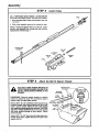
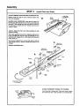
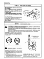
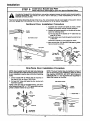
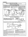
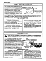
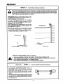
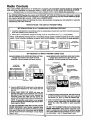
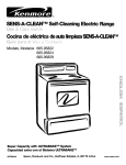
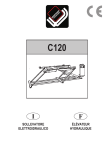
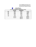
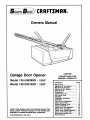
Best /CRI1
FTSMRN
Owners Manual
\
o
o
Garage Door Opener
Model
139.53626SR
- I/2HP
Model
139.53515SR
- I/2HP
FASTEN THIS MANUAL NEAR THE GARAGE DOOR AFTER
INSTALLATION.
PERIODIC CHECKS OF THE OPENER ARE
REQUIRED TO INSURE SATISFACTORY OPERATION.
FOR RESIDENTIAL
USE ONLY.
CAUTION
PLEASE READ THIS
MANUAL CAREFULLY
CONTENTS
Safety Rules ..................
Operation of Your Opener .......
Maintenance Schedule ...
Features of Your Opener..
Specifications ...........
Accessories ............
Carton Check List .......
You'll Need Tools ........
Assembly ....................
Installation Information .........
Installation ...................
Force & Limit Adjustment .......
Safety Reveres Test ............
Setting/Changing
Code .........
Having a Problem ? ............
Repair Parts, Rail Assembly .....
Repair Parts, Installation ........
Repair Parts, Chassis Assembly..
How To Order Repair Parts ......
Maintenance Agreements
.......
Sears Warranty ................
PAGE
2
3
3
4
4
4
5
5
6
9
10
17
18
19
20
22
22
23
24
24
24
Start By Reading These Important
Safety Rules
THIS SAFETY ALERT SYMBOL MEANS CAUTION -- PERSONAL SAFETY OR PROPERTY
DAMAGE INSTRUCTION, READ THESE INSTRUCTIONS CAREFULLY.
THIS GARAGE DOOR OPENER IS DESIGNED AND TESTED TO OFFER REASONABLY
SAFE SERVICE PROVIDED IT IS INSTALLED AND OPERATED IN STRICT ACCORDANCE
WITH THE FOLLOWING SAFETY INSTRUCTIONS.
FAILURE TO COMPLY WITH THE FOLLOWING INSTRUCTIONS
PERSONAL INJURY OR PROPERTY DAMAGE.
MAY RESULT IN SERIOUS,
CAUTION: IF YOUR GARAGE HAS NO SERVICE ENTRANCE DOOR, INSTALL MODEL 53702 EMERGENCY RELEASE
KEYLOCK (PAGE 4). THIS ACCESSORY ALLOWS MANUAL OPERA TION OF GARAGE DOOR FROM OUTSIDE IN CASE
OF POWER FAILURE.
A
binding
doors must
be BALANCED.
repaired. Garage
doors,
EEP GARAGE
DOOR
Sticking
or
door swings, cables, pulleys, brackets and their
hardware are under extreme tension and can
cause
serious
personal
injury. DO NOT
ATTEMPT TO LOOSEN, MOVE OR ADJUST
THEM. Call s garage door serviceman.
J_.
THE SAFETY REVERSE SYSTEM TEST IS VERY
IMPORTANT (page 18). Your garage door MUST
reverse on contact with a 1" obstacle placed on
the floor. Failure to properly adjust the opener
may result in serious personal injury from a
closing garage door. REPEAT THE TEST AT
LEAST ONCE EVERY THREE MONTHS AND
MAKE NEEDED ADJUSTMENTS.
DO NOT WEAR
CLOTHING
while RINGS,
installingWATCHES
or servicingORa LOOSE
garage
door opener.
Fasten theasCAUTION
LABEL ofalongside
the Wall
Control
a reminder
safe operating
procedures.
To avoid serious personal injury from entanglement, REMOVE ALL ROPES CONNECTED TO
THE GARAGE DOOR before
installing the
garage door opener.
DISENGAGE ALL EXISTING GARAGE DOOR
LOCKS to avoid damage to garage door.
Install the Wall Control (or any additional push
buttons) IN A LOCATION WHERE THE GARAGE
DOOR IS VISIBLE, BUT OUT OF THE REACH OF
CHILDREN.
DO NOT ALLOW CHILDREN TO
OPERATE THE WALL PUSH BUTTON(S) OR
TRANSMITTER. Serious personal injury from a
closing garage door may result from misuse of
the opener.
Installation and wiring must be in compliance
with your local building and electrical codes.
CONNECT THE POWER CORD ONLY TO A
PROPERLY GROUNDED OUTLET.
CAUTION: Activate opener only when the door
is in full view, free of obstructions end opener
is properly edjusted. NO ONE SHOULD ENTER
OR LEAVE THE GARAGE WHILE DOOR IS IN
MOTION. DO NOT ALLOW CHILDREN TO PLAY
NEAR THE DOOR.
LIGHTWEIGHT FIBERGLASS, ALUMINUM AND
STEEL DOORS MUST BE SUBSTANTIALLY
REINFORCED TO AVOID DOOR DAMAGE. (See
page 15.) The best solution is to check with your
garage door manufacturer
for an opener
installation reinforcement kit.
Use the emergency release ONLY to disengage
the trolley and, if possible, ONLY when the door
is closed. DO NOT USE EMERGENCY HANDLE
TO PULL DOOR OPEN OR CLOSED.
DO NOT USE THE FORCE ADJUSTMENTS TO
COMPENSATE FOR A BINDING OR STICKING
GARAGE DOOR. Excessive force will interfere
with the proper operation of the safety reverse
system or damage the garage door (page 17).
DISCONNECT ELECTRIC POWER TO GARAGE
DOOR OPENER BEFORE MAKING REPAIRS OR
REMOVING COVERS.
Operation
of Your Opener
CAUTION
•
BEFORE YOU PROCEED, PLEASE READ THE
SAFETY RULES ON PAGE 2 AND OPERATING
INSTRUCTIONS ON THIS PAGE CAREFULLY.
•
TO AVOID DIFFICULTY DURING INSTALLATION, DO
NOT RUN OPENER UNTIL INSTRUCTED TO DO SO.
•
•
DO NOT PERMIT CHILDREN TO PLAY IN DOOR
AREA.
OPERATE ONLY WHEN OPENER IS PROPERLY
ADJUSTED AND
UNOBSTRUCTED.
THE
DOOR
IS
VISIBLE
AND
USING THE OPENER
WHEN OPENER
Your opener can be activated by any of the following devices:
1. If open, the door will close. If closed, the door will open.
2. If closing, the door will reverse.
1. The 3_Function Transmitter. Hold LARGE push button
down until the door starts to move.
IS ACTIVATED:
3. If opening, the door will stop (allowing space for entry and
exit of pets and for fresh air).
2. The Wall Control. Hold push bar down until the door starts
to move.
4. If the door has been stopped in a partially open position,
it will close.
3, The Key Switch or Touch Code Transmitter accessories.
Described on page 4.
OPENING THE DOOR MANUALLY
5. If an obstruction is encountered while closing, the door will
reverse.
6. If an obstruction is encountered while opening, the door
will stop.
7. If the optional 'Infrared Sensor' is installed, the garage door
will reverse in the closing cycle when the invisible beam
is broken. An open door will not close when beam is broken.
The sensor has no effect in the opening cycle.
THE DOOR SHOULD BE FULLYCLOSEDIF POSSIBLE. WEAKOR
BROKEN SPRINGS COULD ALLOW AN OPEN DOOR TO FALL
RAPIDLY.PROPERTY DAMAGEOR SERIOUS PERSONALINJURY
COULD RESULT.DO NOT USE EMERGENCY HANDLE TO PULL
DOOR OPEN OR CLOSED.
The door can be operated manually by disconnecting it from
the opener. Pull down sharply on the red emergency release
handle and lift the door manually. To automatically reconnect
the door to the opener, press the Wait Control push bar.
OPENER LIGHTS will turn on under the following conditions:
when the opener is initially plugged in; when the power is
interrupted; when the opener is activated. They will turn off
automatically after 41/2 minutes or provide constant light when
Light Feature is activated. Bulb size 75 watts maximum.
LOCKOUT FEATURE: prevents trolley from reconnecting
automatically. If you need to use this feature, pull emergency
handle down and back (toward the opener). Trolleywill remain
"Locked-Out"
and door can be raised and lowered manually.
To reconnect trolley, pull emergency handle straight down.
CARE OF THE OPENER
When properly installed, opener will provide high performance
with a minimum of maintenance. The opener does not require
additional lubrication.
CHAIN TENSION ADJUSTMENT: After installation of the
opener and adjustment of forces and limits, the chain may
appear loose. This is normal, To check the chain tension:
disconnect the trolley by pulling the red emergency handle.
If the chain returns to the position described and illustrated
in Step 5 page 9, DO NOT make ANY further adjustments.
TRANSMITTER: The 3-function transmitter will operate more
than one garage door opener, if desired. The other push buttons may also be used to operate 53000 and 53000SR Series
tight controls. Transmitter may be secured to car sun visor
with clip provided. Additional transmitters can be purchased
at any time. Refer to Accessories on page 4.
Any new transmitters must be set to the same code as the
original transmitter. Page 19 explains how to change your
existing code and use the transmitter(s) with other 53000 and
53000 SR receivers. Self service of your radio controls is not
recommended. If service is needed, contact your nearest
Sears Service Center.
Most complaints of unsatisfactory opener operation can be
traced to problems with the door itself. When operated
manually, a properly balanced door will stay in any point of
travel while being supported entirely by its springs.
THE OPENER IS NOT INTENDED TO CORRECT ANY
PROBLEMS THAT ARE CAUSED BY AN UNBALANCED OR
BINDING DOOR, BROKEN DOOR SPRINGS OR BY FAULTY
DOOR HARDWARE.
LIMIT AND FORCE ADJUSTMENTS: These adjustments
must be checked and properly set when opener is installed.
Only a screwdriver is required. Page 17 refers to the limit and
force adjustments. Follow instructions carefully.
REPEAT SAFETY REVERSE TEST AFTER ANY ADJUSTMENT OF FORCE AND/OR LIMITS. Weather conditions
may cause some minor changes in door operation requiring some readjustments, particularly during the first year
of operation.
TRANSMITTER
BATTERY: The 12 Volt battery should
produce power for at least one year. As long as the battery
power is adequate, the transmitter test light will glow when
the push button is pressed (and the opener will Operate).
When the light does not come on, replace the battery. If transmission range lessens, check battery test light.
THE SAFETY REVERSE SYSTEM IS IMPORTANT (See
pg. 18). GARAGE DOOR MUST REVERSE ON CONTACT
WITH A ONE-INCH OBSTACLE PLACED ON THE FLOOR.
FAILURE TO PROPERLY ADJUST OPENER MAY RESULT
IN SERIOUS PERSONAL INJURY FROM A CLOSING
GA R._.GE DOOR.
MAINTENANCE
TO CHANGE BATTERY." Slide the battery compartment
down. Position new 12 Volt battery as directed.
OF YOUR OPENER
AT LEAST 4 TIMES A YEAR
TWICE A YEAR
MANUALLY OPERATE DOOR. If it is unbalanced or binding,
call for professional garage door service.
CHECK TO BE SURE DOOR OPENS & CLOSES FULLY.
Adjust Limits and/or Force if necessary.
REPEAT SAFETY REVERSE TEST. Make any necessary
adjustments (see page 18).
CHECK CHAIN TENSlON.
Adjustifnecessa_
ONCE A YEAR
OIL DOOR ROLLERS, BEARINGS
3
AND HINGES.
cover
FEATURES
OF YOUR
OPENER
1. Motor: Permanently lubricated with automatic reset.
2. Opener Lights: Turn on and off automatically with 41/z
minute illumination for your safety and convenience.
Provide constant light when Light Feature is activated.
7. 3-Function Transmitter: Has three push buttons. Each
button can activate one or more remote control devices.
Opener is factory preset to activate when LARGE push
button on transmitter is pressed.
3. Safety System: Independent up and down force
adjustment. The door reverses automatically when
obstructed in DOWN direction. The door STOPS when
obstructed in UP position
8. Automatic Reconnect: The trolley halves reconnect
for automatic operation when the opener is energized
after emergency disconnect.
4. Easy Limit Adjustment: Limits of door opening and
closing adjusted by turning screws without removing
chassis cover.
5. Digital Radio Controls: The code can he easily
changed by the owner,
6. Emergency Disconnect:
manual door operation.
Pull cord disconnect permits
9. Lock Push Button: When Lock Feature is activated,
opener will not operate from portable transmitters. Door
will OPEN from Wall Control push bar, Key Switch and
Touch Code Transmitter accessories, described below.
Door will CLOSE if Wall Control push bar is pressed
and held through a complete down cycle. If push bar
is released before travel is completed, door will reverse.
SPECIFICATIONS
Type...............
Speed .............
Volts...............
Current ............
SAFETY
MOTOR
Personal ...........
Permanent split capacitor
1500 rpm
120 VoltsAC - 60 Hz. Only
4.5 amperes
Electronic ..........
DRIVE MECHANISM
Gears ..............
Drive ..............
Length of travel ......
Travel rate ..........
Lamps .............
Door linkage ........
16:1 worm gear reduction
Chain & cable with two-piece trolley on
steel Tee-rail
Adjustable to 7Yz fest
6 to 8 inches per second
On when door starts in travel, off 41/z
minutes after stop. Constant light when
Light Control is ON.
Adjustable door arm, Pull cord trolley
release.
Electrical
...........
Limit device ........
Limit adjustment .....
Start circuit .........
Push button and automatic reversal in
down direction. Push button and
Automatic stop in UP direction
Independent UP and DOWN force
adjustment screws
Motor overload protector & low vottage
push button wiring
Circuit actuated by limit nut
Screwdriver adjustment on side panel
Low voltage push button or radio
control
DIMENSIONS
Length (overall) ......
124 inches
Headroom required .. 2 inches
Hanging weight ......
32 pounds
ACCESSORIES
Sears offers many useful accessories
numbers and descriptions.
53778
for your garage door opener. They are illustrated below with sears stock
EXTRA TRANSMITTER:
53710
Standard size. Includes visor clip.
53758
EXTRA TRANSMITTER:
Mini.
INFRARED
REVERSING SENSOR:
An optional system which provides
auxiliary support to the safety features
built into your opener. If the sensor's
invisible beam is broken, a closing
door will reverse and an open door will
not close.
53717
OPEN DOOR INDICATOR:
Provides an illuminated signal when
your garage door is open.
53703
OUTDOOR
KEY SWITCH:
Opens the garage door automatically
from outside when transmitter is not
handy.
53709
DOOR CLEARANCE BRACKETS:
(For Sectional Doors Only)
Replace top brackets and rollers on
door to reduce height of door travel.
For use when installing opener in
garage with low headroom clearance.
53776
TOUCH CODE TRANSMITTER:
Enables homeowner to operate garage
door opener from outside by entering
code on specially designed keyboard.
EMERGENCY RELEASE KEYLOCK
REQUIRED for a garage with NO
service door.
Allows manual operation of garage
door from outside in case of power
failure.
CARTON CHECK LIST
SEARS has packaged your GARAGE DOOR OPENER In two cartons which contain all the parts and hardware
Illustrated below and on Page 22.
Co_r
Rail
Light
3 Function "i'ar_mitter
Grease
Lens (2)
Mode_139_53626(1)
Modd139.53515
(2)
SEPARATE
ALL HARDWARE
ASSEMBLY
l_readed
FOR ASSEMBLY AND INSTALLATION
PROCEDURES
INSTALLATION
HARDWARE
HARDWARE
Clevis Pin
Trolley Rod
11)
5/16" x 2_/4"
5/16--18
x 2-1/2"
_2)
(_
Lock'washer
5/16" (4)
Washered Screw
Master Link
AS SHOWN BELOW.
5/16" - 18 x 1/2"
Rope
Ring (3)
Fastener
[_llllllllllllllvll!ll
5/16"+18 x 1-7/8"
• (mOUnted
12)
(4)
in chassis)
_
12)
_ lflflmlflflflflfl]> _
SheetMetalScrew
6ABx 1"
5/16" - 18
Is)
(2)
Clevis Pin
114 ° - _O X 1/2"
(4) Bolt
Can'_age
Flex Screw
5/16" - 18 x 7/8"
Q
(3)
Loc_ Nut
YOU'LL
++- ©@
1/4" - 20 x 1/2"
Hex Screw
Lockwash_
Nu_
(4)
5/16"- 18 x 7/6-
5/16" (6)
5/16" - 18
14)
(6)
NEED TOOLS
During ammbly and Installation of your opener, the Instructions will call for the use of various hand tools. Have a
stepladder handy, and those tools Illustrated below; hammer, electric drill (& 3/16"and 5/16"dr111bits), screwdriver,
adjustable end wrench or socket wrench kit, wire cutters, tape measure, pliers and hack saw.
Tape Maa_cure
Assembly
TO AVOID INSTALLATION
DIFFICULTIES,
STEP 1
DO NOT RUN THE GARAGE DOOR OPENER UNTIL INSTRUCTED
Assemble
Tee Rail & Attach
Cable
TO DO SO.
Pulley Bracket
TEE RAIL BACK
(TO CHASSIS)
Tee Rail
(End Section)
CAUTION: Do not _ghten the lock nuts until bolt necks
rre seated in square holes.
1/4" Lodx Nut
TeeRail Br_.
(CemerSec_on)
The end section,, of the rail MUST be
connected to the center section from
the direction shown in the illustration.
Otherwise, the trolley will hit against
the nut when installed (Pg. 7).
PROCEDURE: Place the 3 Tee rail sections on a flat
surface for assembly. THIS IS IMPORTANT. The end
sections are identical. THE CENTER SECTION BRACES
MUST BE POSITIONED AGAINSTTHE END SECTIONS
AS SHOWN. Make sure that the "directional arrow"is
pointing toward the front (to deer). Study the illustration
CAREFULLY.
Brace
(When assembled, Tee rail has a front-to-back position as
shown .)
Bolt rail sections together with the hardware illustrated and
from the direction indicated.
SQUARE NECKS ON THE CARRIAGE BOLTS MUST BE
SEATED IN THE SQUARE HOLES IN RAIL SECTIONS.
Screws
_16"-18x7/8"
Tee Rail
(End Se_on)
SquareCarriage
Bob Holes
Cablepulleybracket
attachestoFRONT
ENDofteerail
Cable Pulley
Bradder
\
RAIL FRONT
(TO DOOR)
Lock Washer
5/16"
Nut
Position the cable pulley bracket on front end of tee rail
as shown. Fasten securely with the hardware provided.
IMPORTANT: When tightening screws, be sure to keep
bracket parallel to rail. Otherwise, rail may bow when
opener is operated.
Assembly
STEP 2
InstallTrolley
AS A TEMPORARY STOP, INSERT A SCREWDRIVER
INTO HOLE IN FRONT END OF TEE RAIL AS SHOWN.
1. Attach threaded
as shown.
sha_ to trolley with Iockwasher
2. Slide trolley assembly
and nuts
along rail to screwdriver stop,
NOTE: If trolley hits against the nut on Tee rail, center
section was attached from wrong side and must be
repositioned. Review Step 1.
Temporary Stop
Screwdriver
Cuter
Nut f
LockWasher
Inner Nut
5/16"
5/16"
\
Trolley
STEP 3
Attach
Tee Rail To Opener
USE ONLY THOSE SCREWS MOUNTED IN
TOP OF OPENER CHASSIS. FAILURE TO DO
SO WILL CAUSESERIOUS DAMAGETO THE
OPENER.
Washered Screw
5/16"-18x112"
Flex Screw
5/16"-18x71S"
Trolley
PROCEDURE:
Place the opener chassis on packing
material to protect the cover. For convenience, place a
support under the cable pulley bracket,
Remove 5/16"-18 x 1/2" washered screws mounted in top
of opener chassis. Align holes in back end of Tee rail with
holes in opener chassis. Fasten the rail to the chassis
with washered screws previously removed. CAUTION:
USE ONLY THESE SCREWS! Use of any other screws
will cause serious damage to door opener. Tighten
screws securely.
Chassis
Tee Rail .
(BackSec_on)
Lod_
5/16"-18
5/16"-18
Insert a 5/16"- 18 x 7/8" hex screw into trolley stop hole in
the Tee rail as shown. Tighten securely with a 5/16" lockwasher and nut.
7
Assembly
STEP 4
Install
Chain
and Cable
DO NOT REMOVE CHAIN AND CABLE FROM CARTON.
install Chain
Detach cable from side of carton. Remove master links
from coin envelope..
B
Opener
In This Direc1_n
MASTER LINK PROCEDURE: Insert pins of master link
bar through cable loop and hole in front end of trolley (A)
as shown. Push cap over pins and onto notches. Slide clipon spring over cap and onto pin notches until pins are
locked in place.
Caution: Keep the chain taut while installing
prevent kinking.
to help
With trolleyagainstthe screwdriver,dispensecable around
pulley.Proceedback aroundopener sprocket(B)- be sure
sprocketteeth engage chain-and forward to the threaded
trolley shaft (C).
Use second master link to connect the chain to the flat
end of shaft as shown. Check to make sure chain is not
twisted.
C
Master Link
' I Clip-OnSpring
REMOVE SCREWDRIVER.
Master
kCap
Master Link
Clip-On Spring
i
i
Threaded End
of Trolley Shall
A
h
n
FlatEnd
Tee Rail
1
1
Ca_e
Loop
i
,
Trod_y
Master
Link
Cable
Pulley
InstaJl Chain and Cable
In This DireCtion
ATTACH
SPROCKET
COVER
TO CHASSIS:
Insert back tab in chassis slot. Then bend cover forward
and insert front tab in slot provided on mounting plate.
Tad Slot
Plate
Assembly
STEP 5
Tighten
Lock
Tighten
13ghten
the Chain
CAUTION:
and Cable
Keep the chain from twisting as nuts ere
turned.
PROCEDURE: Thread the inner nut on the trolley in the
direction shown.
Tension is correct when the chain is approximately 1/2"
above the base of the Tee rail midway between the cable
pulley bracket and the opener.
Troll_
To maintain proper tension, tighten outer nut as shown.
Sprocket noise can result if chain is either too loose
or too tight.
Chain
II
II
II
II
CAUTION:
Do not overtighten
Page 3.
ASSEMBLY OF YOUR GARAGE DOOR OPENER
IS NOW COMPLETE.
II
I1
II
II
!l
!!
1/2 Inch
the chain.
Refer
to
J
Base of Tee Rail
BEFORE YOU PROCEED WITH THE INSTALLATION
ALL SAFETY RULES.
OF YOUR GARAGE DOOR OPENER,
BE SURE TO COMPLY WITH
KEEP GARAGE DOOR BALANCED. STICKING OR BINDING DOORS MUST BE REPAIRED. THE GARAGE DOOR,
DOOR SPRINGS, CABLES, PULLEYS, BRACKETS AND THEIR HARDWARE ARE UNDER EXTREME TENSION
AND CAN CAUSE SERIOUS PERSONAL INJURY. DO NOT ATTEMPT TO LOOSEN, MOVE OR ADJUST THEM.
CALL A GARAGE DOOR SERVICEMAN.
DO NOT WEAR WATCHES, RINGS OR LOOSE CLOTHING WHILE INSTALLING OR SERVICING A DOOR OPENER.
AS YOU PROCEED WITH THE REMAINING INSTRUCTIONS IN THIS OWNERS MANUAL, YOU MAY FIND IT HELPFUL
TO REFER TO THE FOLLOWING ILLUSTRATION OF THE FULLY ASSEMBLED AND INSTALLED GARAGE DOOR OPENER.
PowerCord
Cable Pulley
Brad_et
Trotley
Chassis
Trolley
Release
Light
Lens
- Door
IT IS RECOMMENDED
THAT THE OPENER BE INSTALLED 7 FEET OR MORE ABOVE FLOOR WHERE SPACE PERMITS.
CERTAIN INSTALLATION PROCEDURES VARY ACCORDING TO GARAGE DOOR TYPES. WHERE THE DIFFERENCES
OCCUR, BE SURE TO FOLLOW ONLY THOSE INSTRUCTIONS WHICH APPLY TO YOUR DOOR CONSTRUCTION.
Installation
Position and Install Header Bracket
STEP 1
Installation procedures are determined
instructions which refer to your door.
by garage door typeS. Follow only those
THE HEADER BRACKET MUST BE RIGIDLY FASTENED TO THE HEADER WALL. REINFORCE THE WALL
WITH A 2x4 IF NECESSARY. FAILURE TO COMPLY MAY RESULT IN IMPROPER OPERATION OF SAFETY
REVERSE SYSTEM (SEE PAGE 18).
INSTALLATION
SECTIONAL
DOOR AND
1-PIECE DOOR WITH TRACK
1. With the door closed, locate and mark the vertical
conterline of garage door. Extend line onto header wall
above the door.
2. Locate height for header bracket by opening door to
highest point Of travel as shown. Draw an intersecting
horizontal line on header wall 2" above high point. This
height provides travel clearance for top edge of door.
NOTE: When the headroom is not sufficient for 2"
clearance, the bottom edge of bracket may be placed
parallel to the high point of travel.
SECTIONAL DOOR
CURVED TRACK
ONE-PIECE DOOR
HORIZONTAL TRACK
JAMB HARDWARE
Header
Header
e_el
Door Clearance Brackets are designed for low
headroom installations (page 4). They replace the
top brackets end roUere on the garage door, thereby
lowering the high point of door travel. Installation
instructions are contained in the accessory carton.
Trm_
Highest Point
ofTravel
Highestpoint
ofTravel
Track
--Door
Header
_
o.
..."
HaKIware
.1_11
j
LaQ S_rews
_N
_
5/16"XISXl-7/8"
- _
I
,"
'
1-PIECE
Highest
Point of
INSTALLATION
DOOR WITHOUT
1. Find the vertical centerline as described in 1. above.
TRACK
2. Locate height for header bracket by opening door to
highest point of travel as shown. Measure the distance
from top of door to floor. Subtract actual height of door.
Add 8" to the remainder. Refer to example below.
NOTE: If total number of inches exceeds the height
available in your garage, use the maximum height
possible. On finished ceilings, do not position the
bracket closer than 1/2" from ceiling.
ONE-PIECE DOOR
NO TRACK
JAMB HARDWARE
ONE-PIECE DOOR
NO TRACK
PIVOT HARDWARE
Header
3. Position bracket as shown (bottom edge of bracket
on horizontal line end centered on the vertical line).
Mark either top and bottom or left and right bracket
holes, Drill 3/16" pilot holes and fasten bracket.
Highesl Point
of Travel
Header
Bracket
_
of Travel
5ghest Point
lDoor
3. Measuring from top of door, draw an intersecting
horizontal line on the header wall at determined height.
Position the bottom edge of header bracket on the
horizontal line, (>entering bracket on vertical line. Mark
either top and bottom or left and right holes. Drill 3/16"
pilot holes and fasten the bracket with 5/16"xf-7/8" lag
screws as shown above.
EXAMPLE
Jamb
Hardware
Distance from top of door (at
highest point of travel) to floor ...............
Actual height of door .......................
Remainder ...............................
Add ..............................
Bracket height on header wall ...............
(Measure UP from top of door
in closed position.)
10
92"
-88"
4"
+ 8"
=12"
Installation
STEP 2
Attach
Tee Rail to Header
Bracket
PROCEDURE: Position opener chassis on garage floor
below the header bracket. Use packing material base to
protect cover. NOTE: To enable the Tee rail to clear
sectional door springs, it may be necessary to lift the
chassis onto a temporary support.
Header
Bracket
Cle_s Pin
5/16"x2-3/4"
CAUTION: Chassis must either be eecured to support
or held firmly in place by another person.
Raise the Tee rail until pulley and header brackets come
together. Align bracket holes and join with clevis pin as
shown. Insert ring fastener to secure.
Packing
MaterLal
STEP 3
Position
Opener
Chassis
Follow only those instructions
TO PREVENT DAMAGE TO ALL LIGHTWEIGHT
THE OPENER ON THE DOOR.
which apply to your door type as illustrated.
DOORS AND DOORS WITH WINDOWS,
INSTALLATION
INSTALLATION
SECTIONAL
& ONE-PIECE
DOOR WITH TRACK
ONE-PIECE
DOOR
WITH NO TRACK
NOTE: A 2x4 is convenient for setting an ideal doorto-Tee rail distance. It is not necessary where headroom
is insufficient.
PROCEDURE: Measure the distance from floor to top of
door (in fully open position and parallel to the floor).
Using a stepladder as a support, raise opener chassis to
the same distance from the floor (chassis will have a slight
angle as shown).
PROCEDURE:
Raise the opener chassis onto a stepladder. Open garage door. Place a 2x4 on top section of
door near centerline as shown below. Rest Tee rail on 2 x4.
Tee Rail
DO NOT REST
The top of the door should be level with the top of opener.
For maximum efficiency, do net position opener chassis
more than 2 inches above this point.
2x4
Header
Top of Opener
from
FlOOr
11
Installation
STEP 4
THE OPENER
CHASSIS
Hang Opener Chassis
MUST BE SECURELY FASTENED TO A STRUCTURAL
SUPPORT
OF GARAGE.
Three representative Installations are shown. Yours may be different. Hanging brackets should be angled (Fig.l)
or crossed (Fig.2) to provide rigid support, On finished ceUings (Fig.3), attach a sturdy metal bracket (not supplied) to
ceiling joists before installing opener.
PROCEDURE:
On EACH side of the opener measure the
distance from chassis to the structural supports.
FIGURE 2
Cut beth pieces of the hanging bracket to required lengths,
Ratten one end of each bracket and bend or twist to fit
the fastening angles. Do not bend at the bracket hole=.
Drill 3/16" pilot holes in the structural supports. Attach the
flattened ends of brackets to supports with 5/16" xl-7/8"
lag screws.
Lift opener and fasten to hanging bracket as shown. Check
to make sure Tee rail Is centered over door. REMOVE
2x4. Operate door manually. If door hita the rail, raise
header bracket.
5/16"-18x7/8"
Screw
5/16"LockWasher
5/16"-18Nut_
GREASE THE TOP AND THE UNDERSIDE OF RAIL
SURFACE ON WHICH TROLLEY SLIDES. A TUBE OF
GREASE IS SUPPLIED.
FIGURE 3
FIGU RE 1
FINISHED
CEILING
Lag Screws
5/16"xl-7/8"
- 5/16--18x7/8" Screw
5/16" Lock Washer
5/16"-18 Nut
Screws
5/16"xl -7/8"
STEP 5
Attach
Emergency
Release
Rope & Handle
USE EMERGENCY RELEASE ROPE ONLY TO
DISENGAGE TROLLEY. DO NOT USE ROPE
AND HANDLE TO PULL THE DOOR OPEN OR
CLOSED.
Overhand
Knot
PROCEDURE: Thread one end of rope through hole in top
of red handle so 'NOTICE' reads right side up as shown.
Secure with an overhand knot.
NOTE: Knot should be at least 1" from end of the rope
to prevent slipping.
Trolley
Tt_ley
Release Arm
Rope
Thread other end of rope through hole in release arm of
trolley. Adjust rope length so that handle is 6 feet above
the floor. Secure with an overhand knot.
Overhand
Knot
NOTE: If it is necessary to cut rope, heat seal the cut
end with a match or lighter to prevent fraying and/or
raveling.
12
Emergency
Release Handle
Installation
STEP 6
In,t . Wall
Control
LOCATE WALL CONTROL (OR ANY ADDITIONAL PUSH BUTTONS) WHERE GARAGE DOOR IS VISIBLE,
AWAY FROM DOOR AND DOOR HARDWARE AND OUT OF REACH OF CHILDREN. SERIOUS PERSONAL
INJURY FROM A MOVING GARAGE DOOR MAY RESULT FROM MISUSE OF OPENER. DO NOT ALLOW
CHILDREN TO OPERATE WALL PUSH BUTTON(S) OR TRANSMITTER.
FASTEN CAUTION LABEL ON THE WALL NEAR THE WALL CONTROL
OPERATING PROCEDURES.
AS A REMINDER
OF SAFE
PROCEDURE: There are 4 screw terminals on the back
of the Wall Control. Connect the bell wire by color; white
to white, yellow to yellow, black to black and red to red.
Fasten Wall Control to an inside garage wall with 6ABx 1"
sheet metal screws provided (use anchors if installing into
drywall). A convenient place is beside the service door and
OUT OF REACH OF CHILDREN.
Run the bell wire up the wall and across the ceiling to the
garage door opener. Use insulated staples.
The receiver terminals as well as the antenna ere located
on the right side panel of the opener. Position antenna wire
as shown. Then connect the bell wire to the terminal
screws according to color.
k Wall Control
Terminal
Screws
4-Strand BellWire
O_eNe(
Terminal Screws
OPERATION OF WALL CONTROL
WALL CONTROLPUSH BAR
Press to open _ close door.
Press again to REVERSE door during the CLOSING cycle
or to STOP door during OPENING cycle.
LOCK FEATURE
Activate
Lock feature only when door Is closed.
The Lock _ature was designed to prevent of_rstion of the
doo_ from portable transmitters.
The door will OPEN from the Wall Control push bar, Key
Switch and Touch Code Transmitter.The door will CLOSE
if the Wall Control push bar is pressed and held until the
door fully closes. If the push bar is released before down
travel is completed, the door will reverse.
R_ht S_de
Panel
TO ACTIVATE: Press the Lock push button. The indicator
light MUST turn ON.
TO TURN OFF: Press the Lock push button again. The
indicator light MUST turn off. Opener will return to normal
operation.
LIGHT FEATURE
Staples
TO ACI"IVATE: Press the Light push button. The indicator
light MUST turn ON. Opener light will turn on (or remain
on if opener is still In 4-1/2 minute automatic cycle).
TO TURN OFF: Press the Light push button again.
Opener light will turn off.
NOTE: To tom opener light OFF dudng 4-1/2 minute
automatic cycle, press the Light push button twice to activate and then to turn off the Light Features The
light will turn OFF Immediately..
WIRING INSTRUCTIONS FOR ACCESSORIES
Infrared Reversing System:
To white & black opener terminals
Wall ConTrol
Pushbuilon
Key Switch:
To red & white opener terminals
13
Installation
STEP 7
Install
Lights
and Lenses
Make sure antenna wire is bent down before installing
lights and lenses.
75 Watt Max.
Install a 75 Watt maximum light bulb in each socket as
shown. The lights will turn on and remain lit for 4-1/2
minutes when power i-sconnected. After 4-1/2 minutes they
will turn off. For constant light, press the Light push button
on the Wall Control.
Guide
LightLensBUlb
_
If light bulbs burn out prematurely due to vibration,
replace with bulbs specifically packaged for "Garage
Door Openers".
INSTALLING
f//
Lens
Tab
LENS:
NOTE: Force and limit adjustment settings are located
on opener side panels. For convenience, lenses may
be installed after Adjustment Step 3, Page 18.
Slide each lens into the guides as shown. Snap bottom
tabs into lens slots.
STEP 8
Connect
Electric
Power
TO AVOID SERIOUS PERSONAL INJURY FROM ENTANGLEMENT,
TO THE GARAGE DOOR BEFORE OPERATING OPENER.
REMOVE ALL ROPES CONNECTED
TO AVOID DAMAGE TO GARAGE DOOR AND OPENER, MAKE DOOR LOCKS INOPERATIVE BEFORE
CONNECTING ELECTRIC POWER. USE A WOOD SCREW OR NAIL TO HOLD THE LOCKS IN "OPEN"
(UNLOCKED) POSITION.
INSTALLATION & WIRING MUST BE IN COMPLIANCE
OPERATION
WITH LOCAL ELECTRICAL AND BUILDING CODES.
AT OTHER THAN 120V 60Hz WILL CAUSE OPENER MALFUNCTION
AND DAMAGE.
Opener MUST be permanently wired or plugged into a
grounded 3-prong receptacle wired according to local electrical codes. DO NOT use a 2.wire adapter. DO NOT use
an extension cord.
PERMANENT WIRING
CONNECTION
(If required by local code.)
GroundTab
S_v
Green Wire
RIGHT
WRONG
IF LOCAL CODES REQUIRE PERMANENT
WIRING:
DISCONNECT POWER AT THE FUSE BOX
BEFORE PROCEEDING.
White
Wire
PROCEDURE:
Refer to illustration. Make connection
through the 7/8" diameter hole in top of opener chassis.
1. Remove opener chassis cover by removing the cover
screws.
2. Remove attached 3-prong cord.
CAUTION: BE SURE THE UNIT
ACCORDING TO LOCAL CODE.
3. Connect the black (line) wire to black wire on terminal
block; white (neutral) wire to the white terminal wire;
the green (ground) wire to green ground screw.
IMPORTANT
DIFFICULTIES,
14
IS
GROUNDED
NOTE: TO AVOID
INSTALLATION
DO NOT RUN OPENER NOW.
Installation
STEP 9
Install
Door Bracket and Plate
Follow instructions
which apply to your door type as Illustrated
below.
ALWAYS RE NFORCE THE NSIDE OF DOOR--BOTH
VERTICALLY AND HOR ZONTALLY--W TH 2x4
TO
PREVENT
TO LIGHTWEIGHT AND METAL GARAGE DOORS OR ONES WITH GLASS PANELS
BOARDS
OR DAMAGE
ANGLE IRON.
The horizontal brace should be st least 6 feet long. The vertical brace should cover height of top panel. Check
with your garage door manufacturer for a door re=nforcement kit for an opener installs[ion.
Sectional
Door Installation
Procedure
1. Assemble door bracket and plate as shown. Center
bracket on previously marked vertical guideline.
2. Position the bracket assembly on the face of the door
within the following limits:
A) The top edge of the bracket 2"- 4" below the top
edge of the door.
Header
B_acket
VeStal
Center
B) Directly below any structural support across the top
of the door.
SECTIONAL DOOR
Line
Placement depends on your particular needs.
3, Mark and drill 5/16" TOP and BOTTOM fastening holes,
Secure bracket as shown.
DoorBradder&
plate Assy,
Top of Door
DoorBrad_t
Ptate
Nut
Reinfomernent
Board far
Lightw_ht Doors
ReinforcementBoard
Washer
5/16"
One-Piece
Door Installation
NOTE: Door bracket has left and right side fastening
holes. Assemble and install the door bracket and plate
if your installation requires top and bottom fastening
holes.
Procedure
NOTE: The door bracket may be installed on face of
door if required for your installation. (Refer to dotted
line drawing.) HOWEVER, drill 3/16" pilot holes and
substitute 5/16"x 1-1/2" lag screws (not supplied) to
fasten the bracket to the door.
1, Center bracket (with or without plate as required) on
top edge of door as shown. Mark holes.
2. Drill two 5/16" holes and fasten the door bracket with
hardware supplied.
ONEPIECEDOOR
NOTE: If the door has no exposed framing, drill 3/16"
pilot holes and use 5/16" x 1-1/2" lag screws (not supplied) to fasten bracket to top of door.
Door
Bracket
Optional
Face of Door
Inst.'zllation
Vertical
Cenler-Une
15
--
HeaderWall --
DoorBracket
Plate
(Optional)
Installation
STEP 10
Connect
Door Arm to Trolley
Follow only those instructions
SECTIONAL
DOOR
which apply to your door type.
INSTALLATION
Make sure garage door is closed tight. Pull the emergency release handle to disconnect the trolley. Manually move
outer trolley back to the center of inner trolley as shown in Figures A, B and C.
FIG A: Fasten straight door arm section
FIG B: Bring arm sections together, Find
FIG C: If holes in curved arm are ABOVE
to outer trolley with a clevis pin. Secure
two pairs of holes that line up and join holes in straightarm, disconnect straight
the connection with'a ring fastener,
sections,
ann. Cut about 6" from the solid end.
Fasten curved section to door bracket in Select holes as far apart as possible to
Reconnect to trolley with CUT END
the same way.
increase door arm rigidity.
DOWN as shown.
Bring arm sections together. Find two
pairs of holes that line up and join with
A
--
"--
B
Clevis
Washers
5/16"
Lock
Washers
Nots !
.L
Handle
;
Sra<:ket
--
Straight
,
_
Curved
j
ClevisP_Door
ArmDoo_Arm
Proceed
5/16"-181718"
to Step 1, page 17. Trolley will re-engage automatically
ONE-PIECE
DOOR
I
"
_jI
Screws
_'CutThisEnd
when opener is operated.
INSTALLATION
B_l_ket_
ASSEMBLE DOOR ARM: Fasten straight and curved door
arm sections together to longest passible length. With door
closed, connect straight door arm section to door bracket
with a clevis pin+ Secure with a ring fastener.
a_Rit_e_er
Lock
Nuls
Before connecting door arm to trolley, limits of travel must be adjusted on one-piece doors. Umit adjustment screws
are located on left side panel as shown in illustration on Page 17. Follow procedures below.
Fully CloSed
Trolley
Fully Open
Trolley
I Arm
Connector Hole
Open Door
ADJUSTMENT
Door Arm
Door Arm
Bracket
PROCEDURES
OPEN DOOR A_USTMENT
CLOSED DOOR ADJUSTMENT
Decrease UP limit. Turn UP limit adjustment screw counterclockwise 4 complete turns.
Decrease DOWN limit. Turn DOWN limit adjustment screw c_ockwise 8 complete turns.
Press Wall Control push button. 17olley will travel to full open.
Press WaU Control push button. Trolley will travel to full closed.
Manually raise door arm to open position (parallel to floor) and
lift door arm to trolley. The arm should touch trolley just in back
of door arm connector hole as shown in solid line drawing. If arm
does not extend far enough, adjust limit further. One full turn
equals 2" of door travel.
Manually close door and lift door arm to trolley. The arm should
touch trolley just ahead of door arm connector hole as shown in
dotted line drawing. If arm is behind the connector hole, adjust
limit further. One full turn equals 2" of door travel.
CONNECT DOOR ARM TO TROLLEY: With door closed, join curved arm to connector hole in trolley with remaining clevis pin. Secure
with a ring fastener. NOTE: It may be necessary to lift door slightly to make connection.
Run opener through a complete travel cycle. If door has a slight 'downward' slant in full open position, decrease UP limits until door
is parallel to floor.
16
Adjustment
STEP 1
Adjust UP and DOWN
LIMIT ADJUSTMENT settings (left side panel) regulate the
paints at which the door will stop when moving up or down,
NOTE: Door STOPS in the UP direction
if anything
interferes
with door travel. Door REVERSES in the
DOWN direction if anything interferes with the door
travel (including binding or unbalanced doors).
PROCEDURE: Press Wall Control push button or transmitter. Run opener through a COMPLETE TRAVEL
CYCLE. Limit adjustments are not necessary when the
door opens and closes completely and doesn't reverse
unintentionally in the down position.
_0
0"0
Limits
00_F
Lef! Side Panel
I
_
o
LirnitAdjus_'rcent
Screws
The following chart outlines adjustment procedures. Run the opener through a COMPLETE TRAVEL CYCLE AFTER
EACH ADJUSTMENT. NOTE: REPEATED OPERATION OF THE OPENER DURING ADJUSTMENT PROCEDURES MAY
CAUSE MOTOR TO OVERHEAT AND SHUT OFR SIMPLY WAIT 15 MINUTES AND TRY AGAIN. Read chart carefully
before proceeding to Step 2. Use a screwdriver to make limit adjustments.
LIMIT ADJUSTMENT
IF DOOR DOES NOT OPEN COMPLETELY
BUT OPENS AT LEAST FIVE FEET
CHART
IF DOOR REVERSES WHEN CLOSING AND THERE
IS NO INTERFERENCE TO TRAVEL CYCLE
Increase UP travel. Turn the UP LIMIT adjustment screw
clockwise. One turn equals 2" of travel.
If door does not open at least 5 feet: Adjust OPEN
FORCE as explained in Step 2.
Test door for binding: Pull emergency release handle.
Manually open and close door. If door is binding, call a
door serviceman. If door is not binding or unbalanced,
adjust CLOSE FORCE. See Step 2.
IF DOOR DOES NOT CLOSE COMPLETELY
IF OPENER REVERSES
Increase DOWN travel. Turn down limit adjustment screw
counterclockwise.
One turn equals 2" of travel.
If the door still will not close completely, the header bracket
is positioned too high. Repeat Step 1, page 10.
IN FULLY CLOSED POSITION
Decrease DOWN travel. Turn down limit adjustment screw
clockwise. One turn equals 2" of travel.
STEP 2 AdjustForce
DO NOT USE FORCE ADJUSTMENTS TO COMPENSATE FOR A BINDING OR STICKING GARAGE DOOR.
EXCESSIVE
FORCE.WILL
DAMAGE GARAGE
DOOR. INTERFERE WITH PROPER OPERATION OF SAFETY REVERSE SYSTEM OR
Forco Adjustment
Commls
Force Adjustment Controls are located on right side panel
of opener. FORCE ADJUSTMENT
settings regulate
amount of the power required to open and close door.
NOTE: The door STOPS in the UP direction if anything
interferes with its travel. Door REVERSES in the DOWN
direction if anything interferes with its travel (including
binding or unbalanced doors).
ff the force adjustments are set too light, door travel may be
interrupted by nuisance reversals in DOWN direction and
stops in UP direction. Weather conditions can affect the
door movement so occasional adjustment may be needed.
Maximum force adjustment range is 260 degrees, about
3/4 of a complete turn. Do not force controls beyond that
point. Turn force adjustment controls with a screwdriver.
Right Side Panel
FORCE ADJUSTMENT
TEST DOWN (CLOSE) FORCE
Grasp the door handle or door bottom when door is about
halfway through DOWN (CLOSE) TRAVEL. Door should
reverse. If the door is hard to held or doesn't reverse,
decrease DOWN (CLOSE) FORCE by turning the control
in a counterclockwise direction. Make 10 degree turn
adjustments until door reverses normally. After each
adjustment, run opener through a complete cycle.
Adjus+t
Label
CHART
IF DOOR DOESN'T OPEN AT-LEAST 5 FEET
Increase UP (OPEN) FORCE by turning control clockwise.
Make 10 degree turn adjustments until door opens
completely. Readjust UP LIMIT if necessary. After each
adjustment, run opener through a complete travel cycle.
IF DOOR REVERSES DURING DOWN (CLOSE) CYCLE
increase DOWN (CLOSE) FORCE by turning the control
clockwise. Make 10 degree turn adjustments until door
completes close cycle. After each adjustment, run the
opener through a complete travel cycle.
PROCEED TO STEP 3
17
Adjustment
STEP 3
Test Safety
Reverse
System
THE SAFETY REVERSE SYSTEM TEST IS IMPORTANT. GARAGE DOOR MUST REVERSE ON CONTACT
WITH A ONE INCH OBSTACLE PLACED ON THE FLOOR. FAILURE TO PROPERLY ADJUST OPENER MAY
RESULT IN SERIOUS PERSONAL INJURY FROM A CLOSING GARAGE DOOR. REPEAT TEST AT LEAST
FOUR TIMES A YEAR AND ADJUST AS NEEDED.
PROCEDURE: Place a 1-inch obstacle on the floor under
the garage door. Operate door in DOWN direction. The
dOor MUST reverse on the obstruction.
If the door STOPS on the obstruction, it is not traveling
far enough in the DOWN direction. Increase the DOWN
limit by turning DOWN limit adjustment screw counterclockwise 1/4 turn. REPEAT TEST.
NOTE: Make sure limit adjustments do not force the
door arm beyond a straight up and down position. See
the illustration on Page 16,
SECTIONAL DOOR
When the door reverses on the 1-inch obstacle, remove
the obstruction and run the opener through a complete
travel cycle. Door MUST NOT reverse in closed position.
If it does, repeat Adjustment Steps 1, 2 and 3.
ONE-PIECE DOOR
w
I
m
1 Inch Obstrucl_otl
REPEAT
•
•
•
•
ADJUSTMENT
STEP 3 AFTER:
EACH ADJUSTMENT OF DOOR ARM LENGTH, CLOSE FORCE OR DOWN LIMIT.
ANY REPAIR OR ADJUSTMENT OF GARAGE DOOR (INCLUDING SPRINGS AND HARDWARE).
ANY REPAIR OR SUCKLING OF THE GARAGE FLOOR.
ANY REPAIR OR ADJUSTMENT OF THE GARAGE DOOR OPENER.
(Optional)
STEP 4
Instafl Infrared
The INFRARED REVERSING SENSOR provides an
ADDITIONAL
measure of safety against a small child
being caught under a garage door. It uses an invisible
beam which, when broken by an obstruction, causes a
closing door to open and prevents an open door from
closing.
Reversing
/_
After the garage door opener has been completely installed
and adjusted, the INFRARED REVERSING SENSOR
accessory can he installed. Instructions are included with
this optional device.
18
;//
//
"/
//
_I
Sensor
/,# /_
//
_/
_/
//
/"
/1"
//_
t
Radio Controls
EC.C. rules prohibit adjustments to or modification of receiver and transmitter circuitry except for changing the
code setting
and replacing
Manufactured
the transmitter
battery.
THERE
ARE
NO OTHER
under 1 or more of the following U.S. patents: RF.29,525; 4,037.201;
4,750.n8;
USER
SERVICEABLE
4,806,g30.
PARTS.
Other patents pending.
Your 53000SR SERIES garage door opener (with RECEIVER 'SR' CODE BUTTON) has been factory set to operate
with the LARGE push button on the transmitter. The 3-function transmitter(s) can also activate additional garage
door openers and/or light controls - 53000 and/or 53000SR SERIES.
Instructions are given below for matching the code in all transmitters,
transmitter(s) with other receivers.
MATCH/CHANGE
SET CODE SWITCHES
changing your code selection
or using the
THE CODE IN TRANSMITTER(S)
IN ALL TRANSMITTERS
TO MATCHING POSITIONS
1. Locate the code switches in transmitter(s), either by sliding battery compartment cover down or by removing cover
screw and carefully turning case top over.
2. With a pen or a screwdriver, change the setting of one or more switch (to a (+), (-)
or (0) position).
NOTE: Code switches 2 through 9 in ALL transmitters used to operate s receiver must be set to match. (Code
switch 1 on a 3-function transmitter is neutral. Set it to ANY position. It will not affect the code selected).
Standard
3-Function
C:3
3-Function
/F_
_
_
MiniTransmitter
o.1_(1-91
c°dei s.;+l'ch'+
Transmitter
SET RECEIVER TO MATCH TRANSMITTER(S)
53000SR SERIES (WITH RECEIVER CODE BUTTON)
Garage Door Openers and Light Controls
(lllustratten A shows • garage door opener receiver)
CODE
53000 SERIES (WITH RECEIVER CODE SWITCHES)
Garage Door Openers and Light Controls
(Illustration B shows s garage door opener receiver)
Push Button (-)
3 FUNCTION
TRANSMITTER
A
_
GARAGE DOOR
OPENER RECEIVER
(W'dh SR Code Button)
RED W_T
BU<
Select a transmitter push
button to operate receiver
...........
%%%
B
3 FUNCTION
TRANSMITTER
Select a b-at-_mitter
push button to operate
receiver
%
Push Button (0)
|l
SR
GARAGE DOOR
OPENER RECEIVER
Indicator
(With Code Switches)
CodeButton Light
switch #1 to position
that matches selected
Slide
receiver
code
transmitter
push
button
seW_
ithn,c_i_;Vp_siC_tio#_.
3. Press the RECEIVER SR code button on the right side
panel of opener (Illustration A). The indicator light will
turn ON.
(+,o or-)
receiver will operate
with transmitters'
large push button
4. STAND AWAY FROM THE DOOR and press the
selected push button on the transmitter. The indicator
light will tum OFF and door will move. Receiver and
transmitter codes now match and the opener will
operate with the selected push button on the transmitter.
3. Locate the receiver code switches. Set code switch #1
to match transmitter push button you want to use with
that receiver (+), (0) or (-). Refer to illustration 0B).
4. Hold a transmitter (with code switches visible) alongside the receiver. Beginning with RECEIVER code
switch #2, match the position of each transmitter
switch.
NOTE: If transmitter push button is not pressed
within 30 seconds, the indicator light will turn OFF.
Begin again at Step 3.
TO USE THE TRANSMITTER(S) WITH OTHER 53000SR
SERIES RECEIVERS: Select another transmitter push
button to operate the Light Control or additional garage
door opener. Make sure all transmitters used to operate
receiver are set to the same code (Steps I and 2). Repeat
Steps 3 and 4.
TO USE THE TRANSMITTER(S)
WITH OTHER 53000
SERIES RECEIVERS: Select another transmitter push
button to operate the Light Control or additional garage
door opener, Make sure all transmitters are set to a matching code (Steps 1 and 2). Repeat Steps 3 and 4.
t9
Having a Problem?
Review Pages 2 end 3 Before Proceeding
SITUATION
PROBABLE CAUSE & SOLUTION
OPENER DOESN'T OPERATE
FROM WALL CONTROL OR
TRANSMITTER
1. Have you disengaged all door locks? Review Step 8, page 14.
2. Does the opener have electric power? Plug a lamp into the outlet. If it doesn't
light, check fuse box or circuit breaker. (Some outlets are controlled by a wall switch.)
3. Repeated operation may have tripped the overload protector in the motor. Wait
15 minutes. Try again.
4. Is there a build-up of ice or snow under door? Door may be frozen to ground.
Remove any obstruction.
5. Remove bell wire from opener terminals. Short red and white terminals by touching both terminals at same time with a piece of metal (screwdriver or coin), ffopener
rune, check for a faulty wire connection at Wall Control or a short under staples.
OPENER OPERATES FROM
TRANSMITTER
BUT NOT
FROM WALL CONTROL
2. Are wiring connections correct? Review Step 6, page 13.
DOOR OPERATES FROM
WALL CONTROL BUT NOT
FROM THE TRANSMITTER
1. Does the battery test light glow when transmitter push button is pressed? If not,
replace the battery.
1. Is Wall Control push button lit? If not, refer to No. 5 above.
2. If you have two transmitters and only one operates, review the code setting
procedures on page 19. ALL transmitters must be set to same code.
3. Is transmitter(s) operating any other remote control devices? See the code setting
procedures on page 19,
4. Did you press the transmitter button designated to operate garage door opener?
5. Is the Lock Light ON? Turn it OFF.
TRANSMITTER
HAS
SHORT RANGE
1. Check battery test light. If the light is dim, change the battery,
2. Change the location of the transmitter in the car.
3. A metal garage door, foil-backed insulation or metal siding will reduce the
transmission range. An antenna extender kit is available from any Sears sk_re or
service center.
4. Check to be sure antenna on the right side panel of opener extends fully downward.
THE GARAGE DOOR OPENS
AND CLOSES BY ITSELF
1. Is there a neighbor with a garage door opener using the same frequency code?
Change your code. Review page 19.
2. Make sure none of the transmitter push buttons is stuck in the 'down' position.
3. Remove bell wire from opener terminals and operate from transmitter only. If this
solves the problem, the Wall Control is faulty (replace), or there is a short or broken
wire between Wall Control and opener.
DOOR DOESN'T
COMPLETELY
OPEN
1. Is something obstructing the door?
2. If door opens at least 5 feet, travel limits may need to be increased. One turn equals
2 inches of travel. See page 17.
REPEAT SAFETY REVERSE TEST after the adjustment is complete.
3. If door has been working properly but now doesn't open all the way, increase the
UP FORCE. See page 17.
REPEAT SAFETY
DOOR DOESN'T
COMPLETELY
CLOSE
REVERSE TEST after the adjustment
is complete.
1,
Is something obstructing the door?
2. Review the Travel Limits Adjustment Chart on page 17.
REPEAT SAFETY REVERSE TEST after any adiustment
close force or down limit.
of door arm length,
3. Door will not close after the Lock Light is turned ON.
DOOR WON'T
CLOSE
1. The Infrared Reversing Sensor (if you have installed this accessory) may be misaligned or obstructed. Disconnect sensor and check door operation. If the problem
disappears, correct alignment.
2O
Having a Problem? (Continued)
SITUATION
PROBABLE CAUSE & SOLUTION
DOOR REVERSES FOR
NO APPARENT REASON
1. Is something obstructing the door? Pull red emergency release handle. Operate
door manually. If it is unbalanced or binding, call a garage door serviceman to
correct the problem.
2. Clear any ice or snow from garage floor area where garage door closes.
3. Review the Force Adjustment Chart on page 17.
REPEAT SAFETY REVERSE TEST after adjustment
is complete.
4. If door reverses in FULLY CLOSED position, decrease travel limits (see page 17).
REPEAT SAFETY REVERSE TEST after adjustment is complete. THE NEED
FOR OCCASIONAL ADJUSTMENT OF THE FORCE AND LIMIT SETTINGS IS
NORMAL. WEATHER CONDITIONS
IN PARTICULAR CAN AFFECT DOOR
TRAVEL.
5. The Infrared Reversing Sensor (If you have installed this accessory) may be
misaligned or obstructed. Disconnect sensor and check door operation. If problem
disappears, correct alignment.
OPENER
LIGHTS
DO NOT TURN ON
1. Replace light bulbs (75 watts maximum). Use e "garage door opener bulb" if
standard bulb burns out prematurely due to vibration. Vibration may be caused
by loose end panel. Retighten screws.
DO NOT TURN OFF
1. There may be a defective ground at ceiling or wall receptacle.
UNIT MUST BE GROUNDED.
Check the Light Feature on Wall Control. Is it ON? Turn it OFF.
3. If the light doesn't turn off at the Wall Control, check yellow wire at Wall Control
and opener screw terminal connections to be sure excess wire is not touching
other terminals. If the connections are good, replace the yellow wire (it may be
shorted or broken).
2.
OPENER STRAINS OR
MAXIMUM FORCE IS NEEDED
TO OPERATE DOOR
OPENER MOTOR HUMS
BRIEFLY, THEN WON'T WORK
1.
Door may be out of balance or springs are broken. Close door and use emergency
release rope and handle to disconnect trolley. Open and close door manually. A
properly balanced door will stay in any point of travel while being supported entirely
by its springs. If it does not, call a garage door serviceman to correct problem.
Garage door springs are broken. SEE ABOVE.
2. The trolley may he jammed into stop bolts. Pull or push cn door while motor is
humming to release jammed condition. Re-edjust door limits (page 17) to prevent
over-travel.
1.
REPEAT SAFETY REVERSE TEST after adjustment is complete.
3. If the problem occurs on first operation of the opener, door is locked. DISABLE
DOOR LOCK. If chain was removed and reinstalled, motor may be out of phase.
Remove chain; cycle motor to the down position. Observe drive sprocket. When
it turns in clockwise direction and stops in down position, reinstall chain.
REPEAT SAFETY REVERSE TEST after adjustment
OPENER WON'T OPERATE
DUE TO POWER FAILURE
is complete.
1. Use emergency release rope and handle to disconnect trolley. Door can be opened
and closed manually. When the power is restored, press the Wall Control push
button and trolley will automatically reconnect. Refer to Page 3 for'Lockout' Feature.
2. The emergency release Key Lock accessory (for use on garages with no service
door) disconnects the trolley from outside the garage in case of power failure.
CHAIN DROOPS OR SAGS
OPENER NOISE |S DISTURBING
IN LIVING QUARTERS OF HOME
It is normal for chain to droop slightly in the closed door. position. Use emergency
release rope and handle to disconnect trolley. If chain returns to normal height
when the trolley is disengaged and door reverses on a"one-inch obstruction, no
adjustments are needed (see page 9).
1.
If operational noise is a problem because of proximity of the opener to the living
quarters, Vibration Isolator Kit 41A3263 can be ordered from any Sears Service
Center and most Sears stores. This kit was designed to eliminate the 'sounding
beard effect' and is easy to install.
21
Repair Parts
RAIL ASSEMBLY
PARTS LIST
3
KEY
NO.
1
2
3
4
5
6
7
INSTALLATION
KEY
NO.
PART
NO.
1
2
3
41A3472
10A14
41A3476
4
5
6
7
29C 128
41A2828
217A209
41A2829
8
9
10
11
12
12B374
12B380
178B35
178B34
12B350
41A3535
114A 1276
PARTS
PART
NO.
DESCRIPTION
1A995
41 B3243
41 B3244
1B3117
183Bl10
41B2616
41A3473
Master link kit
Inner trolley wlthreadud rod
Outer trolley
Tee rail-center section
Tee rail-end section (each)
Cable pulley bracket assy. (each)
Chain and cable
NOT SHOWN
41A3534
Rail assy. hardware kit (includes
hardware illustrated on page 5)
LIST
DESCRIPTION
Wall Control assembly
12V battery
Transmitter case essy.
(Circuit board not included)
Transmitter visor clip
Emergency rope & handle assy.
4-strand bell wire
Header bracket w/clevis pin
and ring fastener
Door bracket
Door bracket plate
Curved door arm section
Staight door arm section
Hanging brackets
NOT SHOWN
Installation hardware bag (includes
hardware illustrated on page 5)
Owners manual
2
22
Repair Parts
Chassis
Assembly
Parts List
I
19
18
9
5
15
17
14
16
(Oown)
Brown
Contact
UMIT SWITCH
ASSY,
\
Grey
Wire
Drive
Gear
.Contact
KEY
NO.
PART
NO.
1
2
31C290
41A2827
3
41A2817
4
5
6
41B2991
41C2725
41A3493
KEY
NO.
DESCRIPTION
Sprocket cover
Gear and sprocket assy,
Complete with:
Swing washer
Thrust washer
Retaining ring
Bearing plato
Roll pins (2)
Ddve gear
Worm gear
Helical gear w/retainer
Grease
Drive/worm gear kit with grease &
roll pins (2)
Line cord
Wire harness assy. with plug
Receiver logic board assy.
Complete with:
Logic board
End panel with all labels
Ught socket (1)
7
8
19
0
11
12
13
14
15
16
17
18
19
20
23
PART
NO.
Contact
Wire
DESCRIPTION
41A3073 End panel with all labels
175B88
Light socket(each)
108D30-1 Lens(e ash)
30B363 - C_ci-t0r
12A373
Capacitor bracket
41A3150 Terminal block with screws
4tD3058 Universal replacement motorand
bracket assy.
Complete with: Motor,worm, bracket,
hearing assembly, RPM sensor
41A3474 Cover with all labels
41A2818 Helical gear & retainer with grease
41D3452 Limit switch assembly
41C3005 RPM sensor assembly
41A2826 Shaft bearing kit
41A2822 Interruptercup assembly
41A3074 End panel
NOT SHOWN
41A2825 Chassis assy. hardware kit (includes
screws not designated by a number in
illustration)
Bes / CRRFTSMRN®
Owners
Manual
HOW TO ORDER REPAIR PARTS
Now that you have purchased your Sears Garage Door Opener, should a need
ever exist for repair parts or service, simply contact any Sears Service Center and
most Sears Roebuck and Co. stores. Be sure to provide all pertinent facts when
you call or visit.
The MODEL NUMBER is printed on a label located on the right side panel of the
garage door opener.
Garage
All parts listed may be ordered from any service center and most Sears stores.
Door
TO ORDER REPAIR PARTS, ALWAYS GIVE THE FOLLOWING INFORMATION:
• PART NUMBER
• PART DESCRIPTION
• MODEL NUMBER
• NAME OF ITEM
Opener
Models:
If the parts you need are not stocked locally, your order will be electronically transmitted to a Sears Repair Parts Distribution Center for handling.
IMPORTANT NOTE: ff you suspect radio control malfunction, contact your nearest
SEARS Service Center.
139.53626SR
139.53515SR
MAINTENANCE
AGREEMENTS
.........
AT TODAY'S PRICE ....
With nationwide
YOUR
WAY TO BUY TOMORROW'S
SERVICE
service and the benefits of a Sears warranty plus a Sears Maintenance
Agreement, you don't have to worry about costly repairs resulting from normal use.
The Maintenance Agreement does not cover installation or reinstaltation of the product or damage resulting from external causes
such as: acts of abuse, fire, flood, wind, lightning, freezing, etc.
To Purchase
a Sears
Maintenance
Agreement
--
SEARS
FULL
90 DAY WARRANTY
Ask Any Salesperson
or Call Sears
Service
Today.
WARRANTY
ON GARAGE
DOOR
OPENER
For 90 days from the date of purchase, Sears will repair any defect in material or workmanship at no charge.
LIMITED
WARRANTY
From the 91st day until one year from the date of purchase, Sears will furnish replacement parts for any defective
parts, free of charge. You pay for labor.
LIMITED
WARRANTY
ON MOTOR
After 1 year and through 5 years, Sears will furnish replacement parts for any defective parts in motor, free of charge.
You pay for labor.
LIMITATION
ON LIABILITY
Sears will not be liable for lose or damage to property or any incidental or consequential loss or expense from
property damage due directly or indirectly from the use of this product.
Some states do not allow the exclusion or limitation of incidental or consequential damages, so the above limitation
or exclusion may not apply to you.
This warranty does not cover repairs necessary because of operator abuse or negligence, including failure to install,
adjust and operate the opener according to instructions contained in the owners manual.
WARRANTY SERVICE IS AVAILABLE BY SIMPLY CONTACTING THE NEAREST SEARS STORE OR SERVICE
CENTER IN THE UNITED STATES.
This warranty gives you specific legal rights, and you may also have other rights which vary from state to state.
SEARS ROEBUCK AND COMPANY, Dept. 731CR-W Sears Tower, Chicago, IL 60684
© 1990, Sears Roebuck and Company
114A1276
All Rights Reserved
Printed In Mexico