1
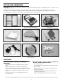
STK# 60010
18" Professional Tile Saw
by
OWNER’S MANUAL
Scie à Carreaux de 460mm
MANUEL D’UTILISATION
Sierra Eléctrica Profesional de 460mm
MANUAL DE OPERACIÓN
LIMITED WARRANTY
Refer to warranty card.
GARANTIE LIMITÉE
Faire référence à la carte de guarantie.
GARANTIA LIMITADA
CAUTION!
Read and follow all safety
and operating instructions
before using this saw.
ATTENTION!
Lire et suivre toutes les directives
de sécurité et d’opération avant
d’utiliser cette scie.
¡AVISO!
Lea y siga todas las instrucciones de
funcionamiento y seguridad antes de
usar esta sierra.
Referirse a la tarjeta de guarantia.
STK# 60010
18" Professional Tile Saw
by
Scie à Carreaux de 460mm
Sierra Eléctrica Profesional de 460mm
TABLE OF CONTENTS
TABLE DES MATIÈRES
CONTENIDO
General Safety Instructions ......................................4
Electrical Requirements ............................................5
Extension Cords...........................................................6
Specific Operation Guide..........................................6
Saw Features ...............................................................6
Set Up and Operation .................................................8
Warning ........................................................................8
Stand Assembly...........................................................9
Attaching Frame to Stand..........................................9
Cutting Head Assembly............................................10
Blade Guard Assembly ............................................10
Diamond Blade Installation ...................................11
Water Tray Installation ............................................11
Water Pump Installation..........................................11
Water Pump Safety ...................................................12
Water Pump Operation & Maintenance ...............12
Cutting Depth .............................................................13
Diamond Blade Do’s & Don’ts.................................13
Cutting Operation ......................................................13
Straight Cuts with Rip Guide ..................................13
45o Angle Cuts with Angle Guide..........................14
Miter Cuts with Miter Block...................................14
Saw Maintenance.....................................................14
“Truing” the Cutting Table.......................................14
Blade Dressing ..........................................................15
Cleaning......................................................................15
Trouble Shooting .......................................................15
Parts List .....................................................................16
Exploded Parts Diagram..........................................16
Directives Générales de Sécurité .........................17
Installations Électriques..........................................18
Cordons d’Alimentation ...........................................19
Guide de Fonctionnement .......................................19
Caractéristiques de la Scie ....................................20
Réglage et Fonctionnement ....................................21
Mise en Garde ...........................................................21
Assemblage de l’Établi ............................................22
Attacher l’Armature de l’Établi...............................22
Assemblage de la Tête de Coupe ..........................23
Assemblage du Protège-Lame ...............................23
Installation de la Lame Diamantée ......................24
Installation du Plateau pour l’Eau .........................24
Installation de la Pompe à Eau ..............................24
Sécurité de la Pompe à Eau....................................25
Fonctionnement et Entretien de la Pompe à Eau............25
Profondeur de la Coupe ...........................................26
À Faire et à ne pas Faire avec la Lame Diamantée.........26
Fonctionnement de la Coupe ..................................26
Coupes Droites avec le Guide de Fente ...............26
Coupes d’Angle à 45° avec le Guide d’Angles ...........27
Coupes d’Onglets avec la Boîte à Onglets ...........27
Entretien de la Scie ..................................................27
"Dressage" de la Table de Coupe .........................27
Alignement de la Lame ............................................28
Nettoyage .................................................................. 28
Dépannage .................................................................28
Liste des Pièces ........................................................29
Diagramme des Pièces Éclaté ...............................29
Instrucciones de Seguridad General ....................30
Requisitos Eléctricos ...............................................31
Cables de Extensión.................................................32
Guía de Operación Específica................................32
Características de la Sierra....................................33
Configuración y Operación .....................................34
Advertencia................................................................34
Ensamblaje del Soporte...........................................35
Sujeción del Armazón al Soporte..........................35
Ensamblaje del Cabezal Cortador..........................36
Ensamblaje de la Protección de la Cuchilla .........36
Instalación de la Cuchilla de Diamante ..............37
Instalación de la Bandeja para Agua ...................37
Instalación de la Bomba de Agua .........................37
Medidas de Seguridad para la Bomba de Agua...38
Operación y mantenimiento de la bomba de agua..38
Profundidad del Corte ..............................................39
Qué Hacer y qué no Hacer con la Cuchilla de Diamante .39
Operación de Corte...................................................39
Cortes Rectos con Guía de Corte...........................39
Cortes en Ángulos de 45 Grados con Guía de Ángulo.40
Cortes de Inglete con Bloque de Ingletes ...........40
Mantenimiento de la Sierra....................................40
Nivelación de la Tabla para Cortar .......................40
Pulido de la Cuchilla................................................41
Limpieza......................................................................41
Resolución de problemas........................................41
Lista de piezas...........................................................42
Diagrama desglosado de piezas............................42
SPECIFICATIONS
MOTOR:
2HP 120V-60Hz 15 AMPS
RPM:
3,450
BLADE:
10"
ARBOR:
5/8"
CUTS TILE: 18" Rip, 13" Diagonal
MAX TILE RIP THICKNESS:
1-1⁄2"
MAX TILE MITER THICKNESS: 3/4"
SAW DIMENSIONS: 40"L x 22"W x 47"H
NET WEIGHT:
116 lbs. (w/stand)
SPÉCIFICATIONS
ESPESIFICACIONES
MOTEUR:
2HP 120V-60Hz 15 AMPS
MOTOR:
2HP 120V-60Hz 15 AMPS
T/M:
3,450
T/M:
3,450
LAME:
25,4 cm (10 po)
CUCHILLA:
25.4 cm (10 pulg.)
TONNELLE:
1,6 cm (5/8 po)
EJE:
1,6 cm (5/8 pulg.)
DÉCOUPES DU CARREAU: Fente de 45,7 cm
(18 po), diagonal de 33 cm (13 po)
CORTA LOSETAS: 45.7 cm (18 pulg.) en corte,
33 cm (13 pulg.) en diagonal
ÉPAISSEUR MAX. DU CARREAU: 3.8 cm (1 1/2 po)
GROSOR MAX. PARA CORTE DE LOSETAS:
3.8 cm (1-1⁄2 pulg.)
ÉPAISSEUR MAX. DE L’ONGLET: 1.9 cm (3/4 po)
DIMENSIONS DE LA SCIE: 101,6 cm (long)
x 55,9 cm (large) x 119,4 cm (haut) (40 po x 22
po x 47 po)
POIDS NET: 52,6 kg (116 lb) (avec l’établi)
GROSOR MAX. PARA CORTE DE INGLETES:
(1.9 cm (3/4 pulg.)
DIMENSIONES DE LA SIERRA: 101,6 cm (L)
x 55,9 cm (AN) x 119,4 cm (AL) (40 pulg. x 22
pulg. x 47 pulg.)
PESO NETO: 52,6 kg (116 lb) (c/soporte)
GENERAL SAFETY INSTRUCTIONS
Read this owner's manual completely and make sure you
understand all of it's safety guidelines.
1.
KEEP GUARDS IN PLACE and in working order.
2.
REMOVE ADJUSTING KEYS & WRENCHES . Before
turning on the tile saw, make sure the keys and
adjusting wrenches have been removed.
15. MAINTAIN TOOLS WITH CARE . Keep tools clean
and in good working condition for maximum safety
performance. Follow instructions for lubricating and
changing accessories.
3.
KEEP WORK AREA CLEAN . Cluttered areas and
benches invite accidents.
16. DISCONNECT TOOLS BEFORE SERVICING – when
changing accessories, such as blades, bits, cutters, etc.
4.
ALWAYS REMAIN ALERT WHEN THE SAW IS IN USE .
Inattention on the part of the operator may lead to
serious injury.
17. REDUCE THE RISK OF UNINTENTIONAL STARTING .
Make sure switch is in OFF position before plugging in.
5.
6.
18. USE RECOMMENDED ACCESSORIES
. Consult the
owner’s manual for recommended accessories. The use
of improper accessories may increase risk of injury.
DON?T USE IN A DANGEROUS ENVIRONMENT . Don’t
use power tools in damp or wet locations or expose
them to rain. Keep work area well lit.
19. DO NOT DRY CUT WITH BLADES DESIGNED FOR
WET CUTS .
KEEP CHILDREN AWAY . All visitors should remain
at a safe distance from work area.
20. MAKE SURE YOU USE THE CORRECT BLADE
for the
material you are cutting. Example: porcelain tile
requires a special blade designed especially for
porcelain.
7.
MAKE WORKSHOP CHILD-PROOF.
Unplug power
tools and secure dangerous tools when not in use. Lock
tool cabinets and workshop doors when unattended.
8.
USE THE RIGHT TOOL . Don’t force a tool or attachment
to do a job for which it was not designed.
It has been designed to operate at maximum safety
and performance levels.
9.
USE THE PROPER EXTENSION CORD . Make sure your
extension cord is in good condition. When using an
extension cord, be sure to use one heavy enough to
carry the current your product will draw. An undersized
cord will cause a drop in line voltage resulting in loss
of power and overheating. Table (see Table 1) shows
the correct size to use depending on cord length and
nameplate ampere rating. If in doubt, use the next
heavier gauge. The smaller the gauge number, the
heavier the cord.
10. DO NOT FORCE THE MATERIAL BEING CUT
let the blade cut at its own speed.
22. CHECK DAMAGED PARTS . Before further use of the
tool, damaged part(s), (i.e., guard) should be carefully
checked to determine that it will operate properly and
perform its intended function. Check for alignment of
moving parts, binding of moving parts, breakage of
parts, mounting and any other condition that may affect
the saw’s operation. A guard or other part that is
damaged should be properly repaired or replaced.
23. ENSURE THAT THERE IS A CONTINUOUS FLOW OF
WATER to both sides of blade during operation.
24. CHECK DIAMOND BLADES CAREFULLY FOR
CRACKS, NICKS, MISSING DIAMOND MATRIX OR
OUT-OF-ALIGNMENT CONDITION
. Replace damaged
blades immediately. DO NOT USE DAMAGED BLADES.
They may cause bodily injury.
. Always
11. WEAR PROPER APPAREL . Do not wear loose clothing,
neckties, rings, bracelets or other jewelry which may
get caught in moving parts. Non-slip foot wear is
recommended. Wear protective hair covering
if you have long hair.
25. DIRECTION OF FEED . Feed work into the blade against
the direction of rotation of the blade only.
26. DO NOT ALTER THE PLUG OR USE A 2-PRONG
RECEPTACLE . This saw is equipped with a 3-prong
electrical plug.
12. ALWAYS USE SAFETY GLASSES . Also use face or dust
mask for commercial cutting operations. Everyday
eyeglasses only have impact-resistant lenses, they are
NOT safety glasses.
27. NEVER LEAVE TOOL RUNNING UNATTENDED
. Turn
power off. Don’t leave tool until it comes to a complete
stop.
13. SECURE WORK . Use clamps or a vise instead of your
hand to hold work when practical. This safety
precaution allows for proper tool operation using both
hands.
14. DON?T OVERREACH
at all times.
21. NEVER STAND ON TOOL . Serious injury could occur if
the wet saw is tipped or if the cutting tool is
unintentionally contacted.
. Keep proper footing and balance
-4-
GENERAL SAFETY (Cont.)
29. POSITIONING OF TILE SAW
A. To avoid the possibility of the appliance plug
or receptacle getting wet, position the tile saw to one
side of a wall-mounted receptacle to prevent water from
dripping onto the receptacle or plug. The user should
arrange a “drip loop” in the cord connecting the saw
to a receptacle (see Fig 1). The “drip loop” is that part
of the cord below the level of the receptacle, or
connector if an extension cord is used, to prevent water
traveling along the cord and coming in contact with the
receptacle.
NOTE: This tool is intended for use on a circuit that has an
outlet that looks like the one illustrated in Fig 2 (B). The tool
has a grounding plug that looks like the plug illustrated in
Fig 2 (A). The green-colored rigid prongs extending from
the adapter must be connected to a permanent ground such
as a properly grounded outlet box.
METAL
SCREW
(A) GROUNDING PIN
(B)
GROUNDED
OUTLET BOX
Fig 2
•
DO NOT MODIFY THE PLUG if it will not fit the outlet.
Have the proper outlet installed by a qualified
electrician.
•
IMPROPER CONNECTION OF THE EQUIPMENTGROUNDING CONDUCTOR CAN RESULT IN A RISK
OF ELECTRIC SHOCK . The conductor with insulation
that is green on the outside (with or without yellow
stripes) is the equipment-grounding conductor. If repair
or replacement of the electrical cord or plug
is necessary, do not connect the equipment-grounding
conductor to a live terminal.
•
CHECK WITH A QUALIFIED ELECTRICIAN or service
personnel if the grounding instructions are
not completely understood, or if in doubt as to whether
the tool is properly grounded.
•
USE ONLY 3-WIRE EXTENSION CORDS that have
3-prong grounding plugs and 3-pole receptacles that
accept the tile saw’s plug.
•
REPAIR OR REPLACE DAMAGED OR WORN CORD
IMMEDIATELY .
•
IF THE PLUG OR RECEPTACLE DOES GET WET, DO
NOT UNPLUG THE CORD . Disconnect the fuse
or circuit breaker that supplies power to the tool. Then,
unplug and examine for presence of water in the
receptacle.
•
ONLY UL-LISTED EXTENSION CORDS SHOULD BE
USED WITH THIS PRODUCT .
•
DO NOT LET YOUR FINGERS TOUCH THE
TERMINALS of plug when installing or removing
the plug to or from the outlet.
Fig 1
B.
If the plug or receptacle does get wet, DO NOT
unplug the cord. Disconnect the fuse or circuit
breaker that supplies power to the tool. Then,
unplug and examine for presence of water in
the receptacle.
ELECTRICAL REQUIREMENTS
•
THIS TILE SAW MUST BE CONNECTED TO A
GROUNDED POWER SOURCE
while in use to protect
the operator from electrical shock (see Fig 2).
•
IN THE EVENT OF A MALFUNCTION OR
BREAKDOWN , grounding provides a path of least
resistance for electrical current to reduce the risk of
electrical shock. The tile saw is equipped with an
electrical cord with a grounding conductor and a
grounding plug. Insert the 3-prong electrical plug into
a 3-pole receptacle that is properly installed and
grounded in accordance with all local codes and
ordinances.
-5-
ELECTRICAL REQUIREMENTS (Cont.)
•
IMPROPER USE OF EXTENSION CORDS MAY CAUSE
INEFFICIENT OPERATION OF YOUR TOOL , which can
result in overheating. Be sure your extension cord is
rated to allow sufficient current flow to the motor. For the
proper gauge for this tile saw, please refer to TABLE 1
below.
•
THIS TILE SAW MUST BE PROPERLY GROUNDED . The
risk of electric shock and bodily injury are greatly
increased if it is not, particularly when used in damp
locations or in proximity to plumbing.
SPECIFIC SAFETY INSTRUCTIONS
EXTENSION CORDS
1.
2.
3.
4.
NOTE: When using an extension cord, ensure all cords are
no smaller than #12 gauge, rated at a 20-amp minimum,
and equipped with 3-prong plugs. Use of anything smaller
may result in overheating or burn out of the motor.
Use only extension cords that are intended for outdoor
use. These extension cords are identified by a marking
“Acceptable for use with outdoor appliances: store
indoors while not in use.” Use only extension cords
having an electrical rating equal to or greater than the
rating of the product. Do not use damaged extension
cords. Examine extension cord before using and replace
if damaged. Do not abuse extension cords and do not
yank on any cord to disconnect. Keep cord away from
heat and sharp edges. Always disconnect the extension
cord from the receptacle before disconnecting the
product from the extension cord.
WARNING - To reduce the risk of electrocution, keep all
connections dry and off the ground. Do not touch plug
with wet hands.
Ground Fault Circuit Interrupter (GFCI) protection should
be provided on the circuit(s) or outlet(s) to be used for
the tile saw. Receptacles are available having built-in
GFCI protection and may be used for this measure of
safety.
1.
Ensure that the directional arrow marked on the blade
corresponds with the rotational direction of the motor.
2.
With the saw disconnected from the power supply,
rotate the blade by hand to ensure it is free from
obstruction.
3.
Always keep the blade-securing arbor and collars
clean.
4.
Ensure that the blade-securing bolt is securely
tightened.
5.
Never try to cut freehand. Always ensure that the tile
to be cut is pressed firmly against the rip guide.
6.
Ensure the material being cut off has sufficient room
to move sideways. Failure to do so may result in the
off-cut binding against the blade.
7.
Never cut more than one tile at a time.
8.
Never cut pieces too small that are not held securely
against the rip guide, and provide enough space for
the hand to be a safe distance from the blade.
9.
Ensure that the table and surrounding area are clear
with the exception of the tile to be cut.
10. Before cutting a tile piece, let the saw blade run freely
for a few seconds. If it makes an unfamiliar sound or
vibrates excessively, switch it off immediately and
disconnect it from the power supply.
USE PROPER EXTENSION CORD . Make sure your
extension cord is in good condition. When using an
extension cord, be sure to use a cord heavy enough to
carry the current your product will draw. An undersized
cord will cause a drop in line voltage, resulting in loss
power and overheating. TABLE 1 below shows the
correct size to use depending on cord length and
nameplate ampere rating. If in doubt, use the next
heavier gauge. The smaller the gauge number, the
heavier the cord.
11. Let the blade reach full speed before commencing
the cut.
12. Let the blade come to a complete stop before
removing any jammed material from around the
blade area.
13. Never allow the blade to run dry. Failure to keep
the water tray at the recommended level will result
in possible over-heating of the diamond blade.
TABLE 1
Ampere Rating
More Not More
Than
Than
0
6
6
10
10
12
12
16
Volts
120V
240V
Total length of cord
25ft.
50ft.
50ft. 100ft. 150ft.
100ft. 200ft. 300ft.
AWG
18
18
16
14
16
16
16
12
16
14
14
14
12
12
Not
Recommended
-6-
INTRODUCTION
We at Q.E.P. would like to congratulate you on selecting the 60010 Tile Saw. We are certain that you will be
pleased with your purchase. QEP is the world’s largest supplier of flooring installation tools and accessories,
and we takes pride in producing the finest tile saws in the industry.
This owners manual contains information necessary to operate and maintain your 60010 safely and correctly.
Please take a few minutes to familiarize yourself with all the contents of this manual. Should you have
questions, feel free to call our Customer Service department, toll free at: 800-777-8665.
Please do not contact the retailer.
Thank you,
QEP
SAW FEATURES
8
7
5
9
6
10
11
4
12
13
15
16
17
18
19
3
20
2
14
21
1
11.
12.
13.
14.
15.
16.
17.
18.
19.
20.
21.
1. Wheels with brakes
2. Folding stand
3. Rip guide
4. 45˚ Miter block
5. Cutting table with measurement rail
6. 10" Continuous rim diamond blade
7. Blade guard
8. 2 HP motor
9. Fan cover
10. Blade guard knob
-7-
Motor support shaft nut
Saw frame
Water Tray
Motor support arm
Belt guard
Water pump outlet
Power housing unit
Thermal overload reset button
Power toggle switch
Blade shaft lock
Water pump
SET UP AND OPERATION
CAUTION! Follow all of the Set Up & Operation Instructions completely before connecting the saw to a power source
or turning the motor on.
The 60010 requires minimal assembly, and as been factory inspected before shipping. Carefully open the container and
remove all saw components and packing materials. Ensure that you have each item before discarding the container or
packing materials. In addition to the hardware bag and wheels, the contents include:
Saw Stand with Locking Wheels
Saw-Frame with Cutting Table
Cutting Head
Water Tray with Drain Plug
Blade Guard
Rip Guide & Miter Block
Water Pump
10" Continuous Rim
Diamond Blade*
Wrenches & Hex Keys
WARNING
FOR YOUR OWN SAFETY READ INSTRUCTION
MANUAL BEFORE OPERATING SAW.
•
Wear eye protection.
PERSONAL INJURY CAN OCCUR IF OPERATED
IMPROPERLY.
•
Keep fingers and loose clothing away from rotating
blade.
•
•
When operating, make sure hands and fingers are
clear from the blade groove, in the cutting table. Severe
abrasion, cuts, or pinching of hands or fingers can occur
as the table is advanced, particularly at the end of its
travel.
Electrical shock can occur if operating instructions
are not followed.
•
Never operate the saw without the blade guard or belt
guard in place.
•
Unplug saw before servicing, when changing cutting
wheels and cleaning.
•
Use saw only with smooth-edge cutting blades free
of openings and grooves.
•
Replace damaged cutting blades before operating.
* The continuous rim diamond tile blade is ideal for cutting ceramic tile. Cutting other materials, including porcelain tile, may require different types of blades.
-8-
STAND ASSEMBLY
ATTACHING FRAME TO STAND
If you are not using the folding stand, set the saw frame
on a solid, flat workbench or table.
B
A
B
A
Fig E1
Fig E2
To attach the Saw Frame to the Stand use the assembly
hardware (Fig. E1). Make sure the wheel brakes are in the
locked position to prevent the Stand from rolling during
assembly (Fig E2). Set the stand on a firm, flat and level
surface. Do not set the stand on soft, uneven ground, or on
debris in the work area. If ground is soft, use a piece of
plywood under the stand to provide a solid and level base.
Fig D1
Fig D2
The saw stand includes 2 cross frame supports:
A & B (Fig D1). Laying the frame supports on their sides,
place Frame B inside Frame A (Fig D2).
Cutter
Head
Fig D3
Frame
Brackets
Fig D4
Wheels
Use 5/16” x 2” bolts, washers and nuts (Fig D3)
to fasten the frame at the axis. Align holes at axis and place
bolt through hole, from outside in (Fig D4). Place the
washer and nut onto bolt and tighten.
Stand
Support Pegs
Fig E3
Fig E4
The Saw will mount directly over the end with the wheels
(Fig E3). Align the frame brackets, on the bottom of the
frame, to the inside of the vertical support pegs on the top
of the stand (Fig E4).
Fig D5
Fig D6
Use two 5/16” x 11⁄ 2” bolts, lock washers and nuts to install
the "U" support braces (Fig D5). Fasten the "U" braces to
the top of the horizontal beam of the saw stand (Fig D6).
Place bolt through the aligned holes. From the underside,
place lock washer and nut, then tighten.
Fig E5
Fig E6
Insert the 1/4” x 3/4” round head bolt into the square hole
of the saw frame and into the stand (Fig E5). Thread the
plastic knob securely onto the bolt, as shown in the
drawing (Fig E6).
Fig D7
Fig D8
3
Use four 1/4” x 1 ⁄4” bolts, washers and nuts (Fig D7) to
attach each wheel to base of Frame B (Fig D8)
-9-
CUTTING HEAD ASSEMBLY
Support Post
Fig F1
Fig G4
Fig G3
Slide the Blade Guard over the support post on the motor
assembly (Fig G3). Secure by tightening the provided
adjustment knob (Fig G4).
Fig F2
To attach the Cutting Head (Fig F1), find the Motor
Support Shaft, loosley inserted in the bottom side of the
unit (Fig F2).
DIAMOND BLADE INSTALLATION
CHANGING THE BLADE:
WARNING! Disconnect the power supply before making
adjustments, maintenance, cleaning or replacing the
blade!
Fig F3
DIAMOND BLADES
Fig F4
Insert the Support Shaft into the Motor Support Arm (Fig
F3). Use provided Shaft Bolt with lock washer and washer,
then tighten (Fig F4).
Fig F5
1.
Use 10” diameter Continuous Rim Wet Diamond
Blades with this saw.
2.
10” Blades with arbor holes of 5⁄8” diameter will fit this
saw.
Fig F6
Fig H1
To stabalize the pivoting Cutting Head, use the provided
large plastic knob and washer (Fig F5), secure the motor
unit to the Vertical Adjustment Bracket (Fig F6).
Fig H2
Tilt the Blade Guard to the highest position and tighten
the adjustment knob (Fig H1). Use the provided wrench,
or adjustable wrench, to remove the blade shaft nut and
outer flange (Fig H2).
BLADE GUARD ASSEMBLY
Blade
Rotation
Fig G1
Fig H4
Fig H3
Place the blade onto the shaft, with the direction arrow
pointing in the same direction of rotation (Fig H3).
Replace the outer flange and blade shaft nut (Fig H4).
Fig G2
The Blade Guard must be installed before the Diamond
Cutting Blade. The Blade Guard (Fig G1) will be attached
using the 11⁄2" adjustment knob (Fig G2).
- 10 -
BLADE INSTALLATION (cont.)
WATER PUMP INSTALLATION
Blade
Shaft
Lock
Fig H5
Fig H6
Fig H7
Fig K2
Fig K1
With one hand, press the Blade Shaft Lock. With the
other, tighten the blade shaft nut (Fig H5). Release the
Blade Shaft Lock after the nut is tightened (Fig H6).
DO NOT OVERTIGHTEN.
Remove the water pump from its box and ensure that it is
not cracked or damaged in any way (Fig K1). Insert one end
of the clear plastic tubing to the fitting at the base of the
Blade Guard (Fig K2).
Fig H8
Loosen the Adjustment Knob and lower the Blade Guard,
and tighten. (Fig H7). Then, slightly loosen the Rear
Support Adjustment Knob and lower the cutting head so
the blade is approx. 1/4" below the cutting surface, tighten
firmly to hold cutting head in place (Fig H8).
Fig K4
Fig K3
Attach the other end over the nipple on the water pump
(Fig. K3). Place the pump in the rear of the water tray with
the tube projected from the side (Fig K4). Be sure the water
level is high enough to cover the water intake filter. Keep all
debris and sediment clear of water intake filter.
CAUTION:
READ "CUTTING OPERATION"
COMPLETELY ON PAGE 12,
BEFORE USING SAW
Decrease
Flow
Increase
Flow
WATER TRAY INSTALLATION
Fig K6
Fig K5
Keep the power cord out of the water and plug it into the 3prong receptacle next to the power/reset housing on the
front top of the saw (Fig K5). The water flow rate can be
adjusted by rotating the Flow Adjuster located on the water
pump (Fig K6). Rotate counterclockwise to increase water
flow, and clockwise to decrease flow.
Water
Fill Line
Fig J1
Fig J2
Slide the water tray into position on the tile saw frame (Fig.
J1). Ensure drain plug is firmly in the drain hole before
filling the water tray (Fig J2). Fill the water tray
approximately 2/3 full - to edge of ledge.
CAUTION:
READ "WATER PUMP SAFETY"
AND "WATER PUMP OPERATION &
MAINTENANCE" ON PAGE 11 COMPLETELY,
BEFORE USING SAW
CAUTION: Do not add chemicals or detergents to the
water
- 11 -
WATER PUMP SAFETY
1. The pump is equipped with a grounding-type
attachment plug. Be sure to connect the plug to a
proper grounding-type receptacle to reduce the risk
of electric shock.
2. Never handle the pump by the cord, with wet hands
or when standing on a wet surface.
3. Do not use the pump to pump anything other than
water, or other compatible liquids. Never use to pump
gasoline, kerosene, or other combustible or corrosive
liquids.
4. Should pump fail, always disconnect from power
source before handling the pump or attempting to
unclog or service pump in any way.
5. Never let the pump operate dry. It is self-cooled by
pumping liquid. Dry use will cause pump damage
and may cause the motor to fail.
WATER PUMP OPERATION &
MAINTENANCE
DO NOT ATTEMPT TO DO ANY REPAIRS YOURSELF AS YOU
WILL VOID YOUR WARRANTY.
1.
Operate the pump with the water-intake nozzle below
the water surface. DO NOT run the pump dry.
Periodically, check the water level, and add water as
necessary to keep water-intake nozzle below the water
surface.
2.
Never attempt to service the pump when it is plugged
in. Also disconnect power supply cord to the saw.
3.
Pump is permanently lubricated–no oiling is needed.
4.
Keep the intake screen clean. Periodically, check for
and clear out any sediment or debris by snapping off
the screen. Rinse out the screen and filter with clean
water. Turn the impeller to ensure it is turning freely. If
the impeller does not turn freely, contact Q.E.P.
5.
Check the power cord for cuts or nicks. Never alter the
cord in any way as this will void your warranty.
- 12 -
CUTTING DEPTH
CUTTING OPERATION
WARNING! Do not attempt to cut pieces too small. Avoid
awkward hand positions where sudden slip could cause
your hand or finger to come in contact with the diamond
blade. When cutting any material, make sure that it is fully
supported. Hold workpiece firmly. DO NOT FORCE THE
MATERIAL INTO BLADE
CAUTION: Make sure that the Mounting Plate Adjustment
Knob and the Rip Guide are tight before operating saw.
Fig M1
Fig M2
The recommended cutting depth for all materials is 1⁄4”
below the top surface of the cutting table (Fig M1). To
adjust cutting depth, loosen Mounting Plate Adjustment
Knob, set the blade height and tighten the Adjustment
Knob securely (Fig M2).
WARNING: Setting the blade too low may cause damage
to the cutting table. If the blade is set too high, it may catch
or grab the material being cut, causing damage and
possible injury.
Fig N1
DIAMOND BLADE DO’s & DON’Ts
The Cutting Table Measuring Guide is marked in Inches on
both sides of the blade for an accurate cutting guide (Fig N1).
DO’s
1. Inspect blades prior to each use for cracks or uneven
wear. Discard cracked, chipped or bent blades.
STRAIGHT CUTS WITH RIP GUIDE
2. Always use manufacturer’s recommendation for
matching the right blade with the right material being
cut.
3. Inspect the arbor shaft for uneven wear before
mounting the blade.
4. Always use blades with the correct arbor size on a
compatible arbor shaft.
5. Ensure the blade is mounted with the rotation arrow in
the proper direction and is securely tightened with a
wrench.
Fig N2
Fig N3
When possible, use the Rip Guide to make straight cuts
(90O) (Fig N2). Place the Rip Guide onto the Measurement
Rail. Slide it to the desired width from the blade, then
tighten the knob. (Fig N3)
6. Always wear proper safety equipment at all times when
operating the saw. Wear goggles at all times when
operating saw.
7. Always ensure a continuous flow of water on both
sides of blade before cutting any material.
DON’Ts
1. Do not operate the saw without all safety guards in
position.
2. Do not operate the saw with blades larger or smaller
than recommended.
3. Do not cut dry with blades marked “Use Wet.”
4. Do not exceed maximum RPMs recommended by the
blade manufacturer.
Fig N4
Fig N5
Position and press the tile firmly against the Rip Guide (Fig
N4). Make sure adequate water is flowing over the blade.
Use both hands to slowly move the tile through the blade
(Fig N5).
5. Do not force the material into the blade. Let the blade
cut at its own speed.
6. Do not cut material not recommended by the blade
manufacturer.
- 13 -
CUTTING OPERATION (cont.)
45o
SAW MAINTENANCE
ANGLE CUTS WITH RIP GUIDE
WARNING! Do not service, clean or maintain the saw
without first turning off the motor and unplugging the saw
from it's power source. Failure to do so may result in
serious injury to the operator.
"TRUING" THE CUTTING TABLE
“Truing” the cutting table may be required occasionally.
The saw blade must be 90˚ to the “tile stop” on the
cutting table to insure accurate cuts, and prevent blade
“binding” while cutting tile.
Fig N6
Fig N7
For 45 angle cuts, use the groove shown (Fig N6). Using
the groove shown (Fig N7). Place Rip Guide onto the
Measurement Rail. Slide it to the desired width from
the blade, then tighten the knob.
O
Fig P1
Fig P2
With a carpenter’s square, place one edge against the
blade and the other edge against the “tile stop”, at the
back of the cutting table (Fig P1). Be sure the inch marks
are aligned (Fig P2).
Fig N8
Fig N9
Position and press the tile firmly against the Rip Guide
(Fig N8). Make sure adequate water is flowing over the
blade. Use both hands to slowly move the tile through
the blade (Fig N9).
Guide Rail
Adjustments
MITER CUTS WITH MITER BLOCK
Fig P3
Fig P4
If the blade does not run flush along the edge of the
carpenter's square (Fig P3) adjustments need to be made.
Slightly loosen the nuts at each end of the Guide Rail (Fig
P4).
Fig N10
Fig N11
For miter cuts, use the miter block attachment. Place the
lip of the miter block on the Measurement Rail (Fig N10).
Place tile onto miter block and into the cutting path
groove (Fig N11). Press the tile firmly against the Miter
Block. Make sure adequate water is flowing over the
blade. Use both hands to slowly move the tile through
the blade.
Fig P5
CUTTING TABLE EXTENSION
Fig P6
Adjust each end of the Guide Rail to align the Cutting
Table until the blade path is completely flush with the
square (Fig P5). Once aligned, carefully tighten the nuts
at both ends of the Guide Rail . (Fig P6).
For greater stability when cutting larger tiles, use the
optional Q.E.P. cutting-table extension #610-1017. For
more info call Q.E.P. Customer Service at 1-800-777-8665
- 14 -
SAW MAINTENANCE (cont.)
TROUBLESHOOTING
BLADE DRESSING
OVERHEATING OF SAW:
After several uses, diamonds on the outer edge of the
blade may become smoothed or “glazed” over. This will
reduce grinding efficiency and may cause the blade to
bend giving the illusion of an alignment problem. When
this occurs, new diamonds need to be exposed, or
"dressed". The diamond blade can be dressed using
the Q.E.P. Rubbing Stone (part # 10022) and following
the following steps.
A. Turn saw off and let it rest until motor is cool to
the touch.
B. Check and clean the ventilation slots, removing
blockage and dirt.
THE SAW DOES NOT START:
A. Confirm power cord is properly plugged in.
B. Check power source voltage is 120V from outlet.
C. Switch is on the "ON" position.
THE PUMP IS FLOWING WATER:
A. Make sure water in tray is high enough.
B. Check water hose for connection or clogs.
Fig Q1
Fig Q2
C. Confirm power cord is properly plugged in.
D. Check for excess debris on intake filter.
Place the Q.E.P. Rubbing Stone against the “tile stop”,
at the back of the cutting table (Fig Q1). Power up the
motor and make sure water is flowing over both sides
of the blade. Make 6-8 cuts off the end of the Rubbing
Stone (Fig Q2). This should expose new diamond
fragments for better cutting.
CUTTING TABLE IS NOT SMOOTH:
A. Thoroughly clean Guide Rails and Cutting Table
Rollers.
B. Inject a little machine oil into the Guide Tube
under the Cutting Table, and spread some on
the Guide Rails.
CLEANING
DO NOT expose the motor to direct water. If excessive
water is introduced into the motor, electric shock and/or
damage to the motor can occur.
If problem continues, contact:
Q.E.P. Customer Service at 1-800-777-8665
DO NOT SERVICE the electric motor's internal
components yourself. Contact Q.E.P. for a list of
authorized service centers
For longest life and best performance, clean the saw after
every use.
Wipe off all exterior surfaces and keep the Cutting Table
clean and free of tile chips and debris. Keep ventilation
slots of the motor clean to prevent overheating
Wipe off both the Guide Bars and the rollers on the
Cutting Table. Inject a little lubricant into the Guide Tube
under the Cutting Table, and spread some on the Guide
Rails.
Pump clean/fresh water for one minute through the water
pump and blade guard to prevent waste build-up &
clogging
Inspect the blade for overall integrity, and rim for wear
and damage.
- 15 -
PARTS LIST
PARTS DIAGRAM
- 16 -