1
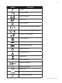
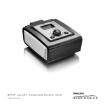
REF 1064858
1070569-01
NS 08/23/10
BiPAP S/T
USER MANUAL
© 2010 Koninklijke Philips Electronics N.V. All rights reserved.
i
BiPAP S/T
user manual
Table of Contents
Chapter 1. Introduction....................................................................................................................................... 1
Package Contents............................................................................................................................................ 1
Intended Use..................................................................................................................................................... 2
Warnings and Cautions.................................................................................................................................. 2
Warnings.................................................................................................................................................... 2
Cautions..................................................................................................................................................... 6
Notes...........................................................................................................................................................7
Contraindications............................................................................................................................................. 7
Patient Precautions.......................................................................................................................................... 8
System Overview.............................................................................................................................................. 8
Control Buttons.....................................................................................................................................10
Available Therapy Modes...................................................................................................................11
Available Therapy Features...............................................................................................................11
Symbols.............................................................................................................................................................13
How to Contact Philips Respironics.........................................................................................................13
Chapter 2. Device Setup.....................................................................................................................................15
Installing the Air Filter..................................................................................................................................15
Where to Place the Device..........................................................................................................................15
Connecting the Breathing Circuit............................................................................................................16
Supplying AC Power to the Device..........................................................................................................17
Display Symbols....................................................................................................................................17
Navigating the Device Screens.................................................................................................................20
Table of Contents
ii
Starting and Stopping the Device..................................................................................................20
Monitor Pressure Screen....................................................................................................................21
Changing the Comfort Settings......................................................................................................22
Changing and Viewing the Setup Options..................................................................................24
Viewing the Information Screen......................................................................................................24
Viewing the Monitoring Parameters Screen...............................................................................25
Viewing Measured Parameters........................................................................................................26
Chapter 3. Device Alarms...................................................................................................................................27
Audible and Visual Alarm Indicators.......................................................................................................27
Alarm LED Indicators...........................................................................................................................28
Alert Audible Indicators......................................................................................................................28
Silencing an Alarm................................................................................................................................29
Alarm Message Screens......................................................................................................................30
Alarm Summary Table..................................................................................................................................30
Troubleshooting.............................................................................................................................................35
Chapter 4. Accessories.........................................................................................................................................39
Humidifier.........................................................................................................................................................39
SD Card..............................................................................................................................................................39
Supplemental Oxygen.................................................................................................................................40
DC Power Cord................................................................................................................................................41
Carrying Case...................................................................................................................................................41
Chapter 5. Cleaning the Device........................................................................................................................43
Cleaning or Replacing the Filters.............................................................................................................43
Cleaning the Tubing......................................................................................................................................44
Service................................................................................................................................................................44
Chapter 6. Specifications....................................................................................................................................45
Chapter 7. EMC Information..............................................................................................................................49
Limited Warranty....................................................................................................................................................53
BiPAP S/T user manual
1
BiPAP S/T
user manual
1. Introduction
This chapter provides an overview of the device.
Package Contents
The BiPAP S/T system may include the following components. Some
components (e.g., humidifier) are optional accessories that may not
be packaged with the device.
AC Power Adapter
(REF 1058190)
Package Contents
Reusable Gray
Foam Filter
Carrying Case
Power Cord
Humidifier
Ventilator
Secure Digital
(SD) Card
User and
Provider Manuals
Flexible Tubing (1.8 m x 22 mm)
(optional 15 mm tubing is also available)
Chapter 1 Introduction
2
Intended Use
The BiPAP S/T device is intended to provide non-invasive ventilatory
support to treat adult patients weighing over 30 kg (66 lbs) and
pediatric patients 7 years or older and weighing over 18 kg (40 lbs)
with Obstructive Sleep Apnea (OSA) and Respiratory Insufficiency.
This device may be used in the hospital or home.
WARNING
The effectiveness of Bi-Flex
has not been established for
pediatric patients.
Warnings and Cautions
CAUTION: US federal law restricts this device to sale by or on the
order of a physician.
Warnings
A warning indicates the possibility of injury to the user or operat
Device Usage
This device is not intended for life support. The device provides Positive
Pressure Ventilation and is indicated for assisted ventilation. The device
does not provide ventilation with guaranteed V T delivery. Patients requiring
ventilation at a predetermined V T are not candidates for Pressure Support
ventilation.
Personnel
Qualifications
This manual serves as a reference. The instructions in this manual are not
intended to supersede your health care professional’s instructions regarding
the use of the device.
The prescription and other device settings should only be changed on the
order of the supervising physician.
The operator should read and understand this entire manual before using
the device.
BiPAP S/T user manual
3
Patient
Circuits
The device should be used only with masks and connectors recommended
by Philips Respironics or with those recommended by the health care
professional or respiratory therapist. A mask should not be used unless the
device is turned on and operating properly. The exhalation port(s) associated
with the mask should never be blocked.
Explanation of Warning: The device is intended to be used with special masks
or connectors that have exhalation ports to allow continuous flow of air out
of the mask. When the device is turned on and functioning properly, new
air from the device flushes the exhaled air out through the mask exhalation
port. However, when the device is not operating, enough fresh air will not be
provided through the mask, and exhaled air may be rebreathed. Rebreathing
of exhaled air for longer than several minutes can in some circumstances
lead to suffocation.
In the event of a power or device failure, audible and visual alarm signals will
activate. The device must be disconnected from the patient immediately. As
is the case with most ventilators with passive exhalation ports, when power
is lost, sufficient air will not be provided through the circuit, and exhaled air
may be rebreathed.
At low EPAP pressures, the flow through the exhalation port may be inadequate
to clear all exhaled gas from the tubing. Some rebreathing may occur.
The device does not have an alarm to detect occlusion of the exhalation
port. Before each use, inspect the patient circuit to verify that the port is
not occluded. Occlusion or partial occlusion can reduce airflow and result in
rebreathing of exhaled air.
Verify the operation of the Patient Disconnect alarm with any changes in the
patient circuit.
Chapter 1 Introduction
4
Oxygen
When using oxygen with this system, the oxygen supply must comply with
local regulations for medical oxygen.
When using oxygen with this system, turn the device on before turning
on the oxygen. Turn the oxygen off before turning the device off. This will
prevent oxygen accumulation in the device.
Explanation of the Warning: When the device is not in operation and the
oxygen flow is left on, oxygen delivered into the tubing may accumulate
within the device’s enclosure. Oxygen accumulated in the device enclosure
will create a risk of fire.
When using oxygen with this system, a Philips Respironics Pressure Valve
(REF 302418) must be placed at the air outlet port. Failure to use the pressure
valve could result in a fire hazard. Refer to the pressure valve instructions for
use for proper use.
If administering fixed-flow supplemental oxygen, the oxygen concentration
may not be constant. The inspired oxygen concentration will vary depending
on the pressure setting, patient breathing pattern, and leak rate. Substantial
leaks around the mask may reduce the inspired oxygen concentration to less
than the expected concentrations. Appropriate patient monitoring should be
implemented.
Oxygen supports combustion. Oxygen should not be used while smoking or
in the presence of an open flame.
Do not connect the device to an unregulated or high pressure oxygen source.
Do not use the device near a source of toxic or harmful vapors.
Operating
Temperatures
Do not use this device if the room temperature is warmer than
35˚ C (95˚ F). If the device is used at room temperatures warmer than 35˚ C,
the temperature of the airflow may exceed 43˚ C (109˚ F). This could cause
irritation or injury to your airway.
Do not operate the device in direct sunlight or near a heating appliance
because these conditions can increase the temperature of the air coming out
of the device.
Bacteria Filter
If the device is used by multiple persons (such as rental devices), Philips
Respironics recommends that a low-resistance, main flow bacteria filter (Part
Number 342077) be installed in-line between the device and the circuit
tubing to prevent device contamination.
BiPAP S/T user manual
5
Improperly
Functioning
Ventilator
If you notice any unexplained changes in the performance of the device, if it
is making unusual sounds, if it has been dropped or mishandled, if water is
spilled into the enclosure, or if the enclosure is cracked or broken, disconnect
the power cord and discontinue use. Contact your home care provider.
Operation of the device may be adversely affected by:
–– Electromagnetic fields exceeding the level of 10 V/m in the
test conditions of EN 60601-1-2
–– Operation of high frequency (diathermy) equipment
–– Defibrillators, or short wave therapy equipment
–– Radiation (e.g., x-ray, CT scan)
–– Magnetic fields (e.g., MRI)
Maintenance
Never operate the device if any of the parts are damaged or if it is not
working properly. Have any damaged parts replaced before continuing use.
Electrical cords, cables, and the power supply device should be periodically
inspected for damage or signs of wear. Replace any damaged parts before using.
Repairs and adjustments must be performed by Philips Respironicsauthorized service personnel only. Unauthorized service could cause injury,
invalidate the warranty, or result in costly device damage.
Power Cord
Be sure to route the power cord to the outlet in a way that will prevent the
cord from being tripped over or interfered with by chairs or other furniture.
This device is activated when the power cord is connected.
Cleaning
To avoid electric shock, unplug the device before cleaning it.
Do not immerse the device in any fluids or spray the device with water or
cleaners. Clean the device with a cloth dampened with an approved cleaner.
Chapter 1 Introduction
6
Cautions
A caution indicates the possibility of damage to the device.
Electrostatic
Discharge (ESD)
Pins of connectors should not be touched. Connections should not
be made to these connectors unless ESD precautionary procedures
are used. Precautionary procedures include methods to prevent
build-up of electrostatic charge (e.g., air conditioning, humidification,
conductive floor coverings, non-synthetic clothing), discharging one’s
body to the frame of the equipment or system or to earth or a large
metal object, and bonding oneself by means of a wrist strap to the
equipment or system or to earth.
Before operating the device, ensure that the SD card cover is replaced
whenever any of the accessories such as the Link Module or modem
are not installed. Refer to the instructions that came with your
accessory.
Do not use antistatic or conductive hoses or conductive patient tubing
with the device.
Condensation
Condensation may damage the device. If the device has been exposed
to either very hot or very cold temperatures, allow it to adjust to room
temperature (operating temperature) before starting therapy.
Extension Cords
Do not use extension cords with this device.
Device Placement
Do not place the device in or on any container that can collect or hold water.
Do not place the device directly onto carpet, fabric, or other flammable
materials.
Do not plug the device into an outlet controlled by a wall switch.
Air Filter
A properly installed, undamaged reusable foam inlet filter is required
for proper operation.
A dirty inlet filter may cause high operating temperatures that may
affect device performance. Regularly examine the inlet filter as needed
for integrity and cleanliness.
Never install a wet filter into the device. You must ensure sufficient
drying time for the cleaned filter.
Cleaning
BiPAP S/T user manual
Do not immerse the device in liquid or allow any liquid to enter the
enclosure or inlet filter.
7
Notes
•• Additional warnings, cautions and notes are located
throughout this manual.
•• Please see the “Limited Warranty” section of this manual
for information on warranty coverage.
Contraindications
The device is contraindicated on patients without a spontaneous
respiratory drive. If any of the following conditions apply to you,
consult your physician before using the device:
•• Inability to maintain a patent airway or adequately clear
secretions
•• At risk for aspiration of gastric contents
•• Diagnosed with acute sinusitis or otitis media
•• Allergy or hypersensitivity to the mask materials where
the risk from allergic reaction outweighs the benefit of
ventilatory assistance
•• Epistaxis, causing pulmonary aspiration of blood
•• Hypotension
When assessing the relative risks and benefits of using this
equipment, the health care professional should understand that this
device can deliver pressures up to 25 cm H2O. In the event of certain
fault conditions, a maximum pressure of 40 cm H2O is possible.
Chapter 1 Introduction
8
Patient Precautions
•• Immediately report any unusual chest discomfort,
shortness of breath, or severe headache.
•• If skin irritation or breakdown develops from the use of
the mask, refer to the mask instructions for appropriate
action.
•• The following are potential side effects of noninvasive
positive pressure therapy:
––
––
––
––
Ear discomfort
Conjunctivitis
Skin abrasions due to noninvasive interfaces
Gastric distention (aerophagia)
System Overview
The BiPAP S/T device is intended to augment patient breathing by
supplying pressurized air through a patient circuit. It senses the
patient’s breathing effort by monitoring airflow in the patient circuit
and adjusts its output to assist in inhalation and exhalation. This
therapy is known as Bi-level ventilation. Bi-level ventilation provides a
higher pressure, known as IPAP (Inspiratory Positive Airway Pressure),
when you inhale, and a lower pressure, known as EPAP (Expiratory
Positive Airway Pressure), when you exhale. The higher pressure
makes it easier for you to inhale, and the lower pressure makes it
easier for you to exhale. The device can also provide a single pressure
level, known as CPAP (Continuous Positive Airway Pressure).
When prescribed, the device can also provide features to help make
your therapy more comfortable. The ramp function allows you
to lower the pressure when trying to fall asleep. The air pressure
will gradually increase until the prescription pressure is reached.
Additionally, the Flex comfort feature provides increased pressure
relief during the expiratory phase of breathing.
BiPAP S/T user manual
BiPAP S/T Device
9
Several accessories are also available for use with the device. Contact your home care provider to
purchase any accessories not included with your system.
The figure below illustrates some of the device features, described in the table below.
SD Card (Accessory) Slot
Air Outlet Port
SD Card Cover
Power Inlet
Tab
Side Cover
Filter Area
Device Features
Feature
Description
Air Outlet Port
Connect the flexible tubing here.
SD Card (Accessory) Slot
If applicable, insert the optional SD card here.
SD Card Cover
If applicable, the optional accessories such as a Link Module or
Modem can be installed here. Refer to the instructions supplied with
your accessory. When not using an accessory, this cover must be in
place on the device.
Connect the power supply cord here.
Power Inlet
Filter Area
A reusable, gray foam filter must be placed in the filter area to
screen out normal household dust and pollen.
Side Cover
If using a humidifier with the device, this side cover can be easily
removed with the release tab before attaching the humidifier. Refer
to the Humidifier Manual for more information.
Chapter 1 Introduction
10
Control Buttons
The figure below shows the display screen and primary control
buttons on the device.
LCD Display Screen
Humidifier Icon
and Number Settings
Control Wheel/
Push Button
Control Buttons
Alarm Silence/
Indicator Button
Ramp Button
Feature
Display Screen
Description
Shows therapy settings, patient data, and other messages. The startup screen is
shown temporarily when the device is first powered.
Humidifier
This symbol lights up when the optional humidifier is attached. The humidifier
Symbol/Settings number settings are only visible when the humidifier is attached and therapy is
active. Please refer to the humidifier user manual for more information.
Control Wheel/ Turn the Wheel to toggle between options on the screen. Press the Wheel to
Push Button
choose an option. Primary function is to turn airflow on/off. Pressing the Wheel
also resets alarms.
Ramp Button
When the airflow is on, this button allows you to activate or restart the ramp
function. This button lights up when therapy is active.
Alarm Silence/
Silences the audible portion of the alarm for a period of time and indicates an
Indicator Button alarm condition.
BiPAP S/T user manual
11
Available Therapy Modes
The table below describes the therapy modes available on the
device:
Therapy Modes
CPAP
S
S/T
Description
Continuous Positive Airway Pressure; CPAP maintains a constant level of
pressure throughout the breathing cycle.
Spontaneous Pressure Support; A Bi-level therapy mode where breaths
are patient-triggered and patient-cycled. The device triggers to IPAP
(Inspiratory Positive Airway Pressure) in response to spontaneous
inspiratory effort and cycles to EPAP (Expiratory Positive Airway Pressure)
during exhalation. The device also cycles a patient-triggered breath if no
patient exhalation effort is detected for 3 seconds. The level of Pressure
Support delivered is determined by the difference between the IPAP and
EPAP settings (PS = IPAP - EPAP)
Spontaneous/Timed Pressure Support; A Bi-level therapy mode where each
breath is patient-triggered and patient-cycled or machine-triggered and
machine-cycled. S/T mode is similar to S mode, except that the device also
triggers machine-triggered breaths based on a set breath rate and cycles
machine-cycled breaths based on a set inspiratory time if the patient does
not spontaneously breathe within a set time.
Available Therapy Features
If prescribed for you, the device provides the following therapy
features.
Bi-Flex Comfort Feature
If enabled, the device provides a comfort feature called Bi-Flex in S
mode only. The Bi-Flex attribute adjusts therapy by inserting a small
amount of pressure relief during the latter stages of inspiration and
during active exhalation (the beginning part of exhalation). Bi-Flex
levels of 1, 2, or 3 progressively reflect increased pressure relief that
will take place at the end of inspiration and at the beginning of
expiration.
WARNING
The Bi-Flex feature is for adult
patients only.
Chapter 1 Introduction
12
Ramp
If enabled, the device is equipped with a linear ramp function. The
Ramp feature will reduce the pressure and then gradually increase
(ramp) the pressure to the prescription pressure setting so patients
can fall asleep more comfortably.
Rise Time
If enabled, the device provides a feature called Rise Time in S and
S/T modes. Rise time is the amount of time it takes the device to
change from the expiratory pressure setting to the inspiratory
pressure setting. Rise time levels of 1, 2, or 3 progressively reflect
slowed response of the pressure increase that will take place at the
beginning of inspiration. A setting of 1 is the fastest rise time while
a setting of 3 is the slowest. Providers should adjust the rise time to
find the most comfortable setting for the patient. Rise time cannot be
adjusted when Bi-Flex is enabled.
BiPAP S/T user manual
13
Symbols
The following symbols appear on the device and power supply.
Symbol
Description
For Airline Use. Complies with RTCA DO-160F
section 21, category M.
DC Power Connector
Consult accompanying instructions for use.
Type BF Applied Part
Class II (Double Insulated)
Drip Proof Equipment
Caution! U.S. federal law restricts this device to
sale by or on the order of a physician.
For indoor use only
Do not disassemble
How to Contact Philips Respironics
To have your device serviced, contact your home care provider. If you need to contact Philips
Respironics directly, call the Customer Service department at 1-724-387-4000 or 1-800-345-6443.
You can also use the following address:
Respironics Inc.
1001 Murry Ridge Lane
Murrysville, PA 15668
Chapter 1 Introduction
14
BiPAP S/T user manual
15
BiPAP S/T
user manual
2. Device Setup
Installing the Air Filter
The device uses a gray foam filter that is washable and reusable.
CAUTION
The reusable filter screens out normal household dust and pollen.
A properly installed, undamaged
It must be in place at all times when the device is operating. One
gray foam filter is required for
reusable gray foam filter is supplied with your device. If your filter is
proper operation.
not already installed when you receive the device, you must install it
before using the device. To install the gray foam filter, insert it into the
filter area.
Where to Place the Device
Place the device upright on a firm, flat surface somewhere within
easy reach of where you will use it, at a level lower than your sleeping
position. Make sure the filter area on the back of the device is not
blocked by bedding, curtains, or other items. Air must flow freely
around the device for the system to work properly. Make sure the
device is away from any heating or cooling equipment (e.g., forced air
vents, radiators, or air conditioners).
CAUTION
Do not place the device directly onto
carpet, fabric, or other flammable
materials.
CAUTION
Do not place the device in or on any
container that can collect or hold
water.
Chapter 2 Device Setup
16
Connecting the Breathing Circuit
To use the system, you will need the following accessories in order to
assemble the recommended circuit:
•• Philips Respironics interface (nasal mask or full face mask)
with integrated exhalation port, or Philips Respironics
interface with a separate exhalation device (such as the
Whisper Swivel II)
•• Philips Respironics 1.83 m (6 ft.) 22 mm flexible tubing or
the optional 15 mm flexible tubing
•• Philips Respironics headgear (for the mask)
Complete the following steps to connect your breathing circuit to the
device:
1. Connect the flexible tubing to the air outlet on the side of the device.
Note: If required, connect a bacteria filter to the device air outlet, and then
connect the flexible tubing to the outlet of the bacteria filter.
Note: When using the bacteria filter, the device performance may be affected.
However, the device will remain functional and deliver therapy.
2. Connect the tubing to the mask. Refer to the instructions that
came with your mask.
3. Attach the headgear to the mask if necessary. Refer to the
instructions that came with your headgear.
WARNING
If the device is used by multiple
persons (such as rental devices), a
low-resistance, main flow bacteria
filter should be installed in-line
between the device and the circuit
tubing to prevent contamination.
WARNING
The exhalation device (Whisper
Swivel II) or exhalation port
(on masks with an integrated
exhalation port) is designed to
exhaust CO2 from the patient circuit.
Do not block or seal the ports on the
exhalation device.
WARNING
If you are using a full face mask
(a mask covering both your
mouth and your nose), the mask
must be equipped with a safety
(entrainment) valve. You must
ensure that the entrainment valve is
functioning properly.
CAUTION
Condensation may damage the
device. If the device has been
exposed to either very hot or very
cold temperatures, allow it to adjust
to room temperature (operating
temperature) before beginning the
setup procedure to the left. Do not
operate the device outside of the
operating temperature range shown
in the Specifications chapter.
BiPAP S/T user manual
17
Supplying AC Power to the Device
Complete the following steps to supply AC power to the device:
1. Plug the socket end of the power cord (included) into the power
supply (also included).
2. Plug the pronged end of the power cord into an electrical outlet
that is not controlled by a wall switch.
3. Plug the power supply cord’s connector into the power inlet on
the back of the ventilator.
4. Ensure that all connections are secure.
Important! To remove AC power, disconnect the power supply cord from the
WARNING
This device is activated when the
power cord is connected.
Note: See Chapter 4 for
instructions on using DC Power.
WARNING
Be sure to route the power cord to
the outlet in a way that will prevent
the cord from being tripped over or
interfered with by chairs or other
furniture.
electrical outlet.
Display Symbols
The following symbols may display on the device in place of text if
the display language selected by your home care provider is “Icon.”
Symbol
Description
Activate Mode
Alarm
Apnea
Back
Backlight
Flex therapy feature
Blower Hours
BPM
Breaths Per Minute
Comfort Setting
Chapter 2 Device Setup
18
Symbol
Description
Flex Control
hPa/cmH2O
Humidifier
Information
Language
Leak
Machine Hours
Min Vent
Minute Ventilation
Mode
No
No Settings Available
Off (disabled)
On (enabled)
Patient Disconnect
Provider Mode
Ramp Time
Ramp Start Pressure
Reinsert SD Card
Reset Blower Hours
Reset Therapy Hours
RR
BiPAP S/T user manual
Respiratory Rate
19
Symbol
Description
Rise Time
Rise Time Control
SD Card Corrupted
SD Card Full
SD Card Inserted
SD Card Inserted: Prescription Accepted
SD Card Inserted: Prescription Rejected
SD Card is Write-Protected
SD Card Removed
Setup
Setup Parameter Display
Therapy (Blower Off )
Therapy (Blower On)
Therapy Hours
TI
Timed Inspiration
Ventilator Inoperative
VTE
Exhaled Tidal Volume
Tubing Type
Tubing Type Control
Yes (Selection Confirmed)
Chapter 2 Device Setup
20
Navigating the Device Screens
Turn the Wheel to toggle between options and settings on the
screen. Press the Wheel to choose an option or setting that is
highlighted. If you choose “Back” or the
icon on any screen, it
will take you back to the previous screen.
Starting and Stopping the Device
Note: Your device will either
display in icon mode or text
mode. Examples will be shown
in both modes.
1. Supply power to the device.
2. The Main Menu screen appears, shown below.
Icon View - Blower Off
Therapy
Comfort
Info
Setup
Text View
Note: The screens shown in
this manual are examples
only. Information on your
device screens may be different
depending on your prescription
settings.
Icon View - Blower On
3. Put on your mask assembly.
4. Turn the Wheel to toggle between the four options. Highlight
Therapy or the
icon. Press the Wheel to turn on the airflow
and begin therapy. The Monitor Pressure screen will appear,
described in detail in the next section.
Main Menu
Note: If you are having trouble
with your mask, refer to the
instructions supplied with the
mask.
5. Verify that the device beeps and the red alarm LED lights up
each time therapy is started. If the device does not operate
accordingly, contact your home care provider, as the alarm
system may not be fully functional.
6. Make sure that no air is leaking from your mask into your eyes.
If necessary, adjust the mask and headgear until the air leak
stops. See the instructions provided with your mask for more
information.
7. If you are using the device in a bed with a headboard, try placing the
tubing over the headboard. This may reduce tension on the mask.
8. From the Monitor Pressure screen, press and hold the Wheel for
approximately 2 seconds to turn off therapy and return to the
Main Menu.
BiPAP S/T user manual
Note: A small amount of leak is
normal and acceptable. Correct
large mask leaks or eye irritation
from an air leak as soon as
possible.
21
9. Verify that the device beeps when therapy is stopped. If the
device does not operate accordingly, contact your home care
provider, as the alarm system may not be fully functional.
Monitor Pressure Screen
From the Main Menu, if you select Therapy and then press the Wheel,
the following Monitor Pressure screen appears.
S/T
20.0 cm H2O
RR
15
The Monitor Pressure screen displays the following items:
••
••
••
••
••
Pressure
Therapy Mode (CPAP, S, or S/T)
Timed Breath Indicator ( )
Icon Bar
Measured Parameters
Sample Monitor Pressure
Screen
Note: The Ramp symbol will also
appear on the display if Ramp
is active.
Note: If an accessory is attached
to the therapy device, additional
symbols may appear on the
Monitor Pressure screen. Refer
to the instructions provided
with the accessory for more
information.
The top of the display shows a group of status symbols. The symbols
will only appear if the conditions described in the following table exist.
Symbol
Description
The Provider Access symbol indicates the device is in
Provider mode.
FLEX
The Flex symbol displays only when the Bi-Flex
therapy feature is enabled by the provider.
The Apnea alarm symbol displays only when the
Apnea alarm is enabled by the provider.
The Patient Disconnect symbol displays only when the
Patient Disconnect alarm is enabled by the provider.
Chapter 2 Device Setup
22
The bottom section of the display shows additional measured
parameters which may include:
••
••
••
••
Note: The measured parameters
display one at a time on-screen.
Respiratory Rate (RR)
Tidal Volume in milliliters (ml)
Minute Ventilation (Min Vent) in liters per minute (lpm)
Leak in lpm
Changing the Comfort Settings
FLEX
2
4
3
Icon View
Comfort
Your device is equipped with optional Flex, Ramp, and Rise Time
features that your health care professional may prescribe for you.
From the Main Menu, when you highlight the Comfort option and
press the Wheel, the Comfort Settings screen below appears.
Back
Bi-Flex
Ramp start
Rise time
Note: If your home care provider
has locked a comfort setting, a
lock symbol ( ) appears next to
the value. You cannot adjust any
settings that are locked.
2
4
3
Text View
Flex Setting
The Flex comfort setting allows you to adjust the level of pressure
relief that you feel during therapy. Your home care provider can
enable, lock, or disable this feature. When your provider enables
Flex, a level will already be set for you on the device. If this is not
comfortable, you can increase or decrease the setting from 1 to 3. A
setting of 1 provides a small amount of pressure relief, with higher
numbers providing additional relief.
BiPAP S/T user manual
Note: If no comfort settings are
available, the Comfort Settings
screen displays “No Settings
Available.”
Sample Comfort Settings
Screen
23
Ramp Start Setting
The device is equipped with an optional ramp feature that your
home care provider can enable or disable. This feature reduces the
air pressure when you are trying to fall asleep and then gradually
increases (ramps) the pressure until your prescription setting is
reached, allowing you to fall asleep more comfortably.
Note: If the ramp feature is
disabled, nothing will happen
when you press the Ramp
button.
If ramp is enabled on your device, after you turn on the airflow, you
can press the Ramp button on the top of the device. Use the Ramp
button as often as you like during the night. When Ramp is enabled,
the Ramp icon (
) appears on the Monitor Pressure screen.
The Ramp Start pressure setting can be increased or decreased from
4 to the CPAP setting (if in CPAP therapy mode) or the EPAP setting
(for all other therapy modes).
Rise Time Setting
Rise time is the time it takes for the device to change from EPAP to
IPAP. If rise time is prescribed for you, you can adjust the rise time
from 1 to 3 to find the setting that provides you with the most
comfort. A setting of 1 is the fastest rise time, while 3 is the slowest.
Note: If Flex is enabled, the rise
time setting will be fixed at 2.
Tubing Type Setting
This setting allows you to select the correct tubing diameter size
that you wish to use with the device. You can choose either “22” for
any Philips Respironics 22 mm tubing, or “15” for the optional Philips
Respironics 15 mm tubing. This selection allows you to control the
resistance in the tube to provide the most comfortable pressure
setting.
WARNING
If you are using the optional
Philips Respironics 15 mm
tubing, the device tubing type
setting must be set to 15. If your
device does not have the tubing
type setting, you must use the
Philips Respironics 22 mm
tubing selection.
Chapter 2 Device Setup
24
Changing and Viewing the Setup Options
Note: The screen will only show
From the Main Menu, when you highlight the Setup option and press 4 selections at a time. As you
rotate the Wheel to toggle over
the Wheel, the Setup screen below appears.
different options, the screen will
slide up and down accordingly.
cmH2O
Setup
Back
Back light
on
hPa/cmH2O
cmH2O
Humidifier
3
Icon View
3
Sample Setup Screen
Text View
The following options appear on the Setup screen:
•• Backlight - You can enable or disable the button LED
backlight on the device.
•• hPa/cmH2O - You can select either hPa or cmH2O as the
default unit of measure on the device.
•• Humidifier - You can view and adjust the humidifier
setting here. This setting displays when a humidifier is
attached. Please refer to the humidifier manual for more
information.
Viewing the Information Screen
From the Main Menu, when you highlight the Info option and press
the Wheel, the Information screen below appears. You cannot change
settings on the Information screen.
Note: The Info screen is only
for reference. Your home care
provider may periodically ask
you for this information.
Back
Monitor Parameters
890.1
Blower Hours
890.1
902.0
Machine Hours 902.0
890.1
Icon View
Info
Therapy Hours
890.1
Sample Information Screen
Text View
Note: If an accessory is attached
to the therapy device, additional
items may appear on the
Information screen. Refer to the
instructions provided with the
accessory for more information.
BiPAP S/T user manual
25
The following items appear on the Information screen:
•• Monitor Parameters - Displays the available parameters.
•• Therapy Hours - Displays the average amount of time
therapy is received over a 7 day and 30 day period.
•• Blower Hours - Displays the total number of hours that
the blower has been on. It can be reset by your home
care provider. This setting allows the provider to track
device usage between patients.
•• Machine Hours - Displays the total number of hours
that the blower has been on. This cannot be reset by the
home care provider.
Viewing the Monitor Parameters Screen
There are two ways to access the Monitor Parameters screen:
•• From the Monitor Pressure screen, press the Alarm
Silence and Ramp keys simultaneously for two seconds.
•• From the Information screen, select the Monitor
Parameters setting.
The parameters displayed in this screen are described in the previous
table. A sample screen is shown below.
cmH2O
4.0
6
Vte
200
RR
10
Note: The information
displayed in the last box shown
on the sample screen will vary
depending on what accessory is
attached to the therapy device.
This box will be empty (as shown
here) if no accessory is attached.
Please refer to the instructions
included with your accessory for
more information.
MinVent
6
Sample Monitor Parameters
Screen
Press the Wheel to exit the Monitor Parameters screen and return to
the previous screen.
Chapter 2 Device Setup
26
Viewing Measured Parameters
Several measured parameters can be viewed on-screen. The
following table describes each measured parameter. The measured
parameters that display on the Monitor Pressure screen only appear
one at a time. The Setup Parameter Display setting on the Setup
screen allows you to choose which measured parameters you want
displayed. The parameters below appear on both the Monitor
Pressure and Monitor Parameters screens.
Parameter
Note: If an accessory is
attached to the therapy device,
additional parameters may
appear on-screen. Please refer
to the instructions included
with your accessory for more
information.
Description
Pressure
Displays the current patient pressure.
Leak ( )
The estimated leak is the average leak value for the last 6 breaths. The display is
updated at the end of each breath.
Respiratory Rate (RR) This is the average of the previous 6 breaths. If the mode supports machine-triggered
breaths, this display will be the total breathing rate (spontaneous breaths + machine
breaths). The display is updated at the end of each breath.
Minute Ventilation
(MinVent)
The estimated Exhaled Minute Ventilation is based on the average of the last 6
breaths. The display is updated at the end of each breath.
Exhaled Tidal
Volume (Vte)
The estimated Exhaled Tidal Volume is obtained by the integration of patient flow.
The display is updated at the end of each breath.
BiPAP S/T user manual
27
BiPAP S/T
user manual
3. Device Alarms
This chapter describes the ventilator alarms and what you should do
if an alarm occurs.
There are three types of alarms:
•• High Priority – Require immediate response by the
operator
•• Medium Priority – Require prompt response by the
operator
•• Low Priority – Require operator awareness. These alarms
alert you to a change in the ventilator status.
Additionally, the ventilator also displays informational messages and
confirmation alerts that notify you of conditions that need attention
but are not alarm conditions.
Audible and Visual Alarm Indicators
Note: If multiple alarms occur
at the same time, only the
highest priority alarm will be
active. The precedence is in the
following order: high priority,
medium priority, then low
priority. When multiple priority
alarms are active, the highest
priority LED light displays and
the highest priority audible
indicator sounds. On the display
screen, the last highest priority
alarm displays.
Note: Informational messages
are a lower precedence than
alarms and will not display on
the screen if any alarm is active.
When an alarm condition occurs:
•• The alarm LED indicator on the Alarm Silence/Indicator
button lights
•• The audible alarm sounds
•• A message appears on the screen describing the type of
alarm
Chapter 3 Device Alarms
28
Alarm LED Indicators
The Alarm Silence/Indicator button lights up as follows whenever an
alarm is detected:
•• Red Flashing Indicator – High priority alarm is detected.
•• Yellow Flashing Indicator – Medium priority alarm is
detected.
•• Yellow Solid Indicator – Low priority alarm is detected.
The Alarm Silence/Indicator button does not light up when
informational messages display.
Alert Audible Indicators
An audible indicator sounds whenever a power failure or a high,
medium, or low priority alarm is detected. Additionally, an audible
indicator sounds for informational messages and to confirm that
certain actions have occurred (for example, when an SD card is
inserted or removed from the device).
•• Ventilator Inoperative – When a ventilator inoperative
alarm occurs, a continuous audible indicator sounds.
The alarm descriptions later in this chapter display this
indicator as:
•• Power Failure – When a power failure occurs, a series of
beeps sounds in a 1 beep pattern, repeating one second
on, then one second off. The alarm descriptions later in
this chapter display this indicator as: •
•
•• High Priority – When a high priority alarm is active, a
series of beeps sounds in the following pattern, which is
repeated twice: 3 beeps, a pause, and then 2 more beeps.
This indicator continues until the cause of the alarm is
corrected or the audible alarm is silenced. The alarm
descriptions later in this chapter display this indicator as:
••• ••
••• ••
BiPAP S/T user manual
29
•• Medium Priority – When a medium priority alarm is
active, a series of beeps sounds in a 3-beep pattern. This
pattern repeats until the cause of the alarm is corrected
or the audible alarm is silenced. The alarm descriptions
later in this chapter display this indicator as: • • •
•• Low Priority – When a low priority alarm is active, a series
of beeps sounds in a 2-beep pattern. This pattern repeats
until the cause of the alarm is corrected or the audible
alarm is silenced. The alarm descriptions later in this
chapter display this indicator as: • •
•• Informational Messages and Confirmation Audible
Indicators – When an informational message appears
on screen, a brief, 1- beep audible indicator sounds.
Additionally, when the device detects that a certain
action has been completed (for example, when an SD
card is inserted or removed from the device) a brief, 1beep audible indicator sounds. The descriptions later in
this chapter display this indicator as: •
Silencing an Alarm
You can silence an alarm by pressing the Alarm Silence/Indicator
button. This will silence the alarm for one minute. If another alarm
occurs while the silence period is active, the audible alarm portion of
the new alarm will not sound until the silence period expires. When
the silence period expires, the alarm’s audible alarm is reactivated.
Touching the Alarm Silence/Indicator button while the silence period
is active will restart the silence period.
Chapter 3 Device Alarms
30
Alarm Message Screens
When an alarm message is activated, an alarm screen is displayed,
showing the text or icon specific to the most recent, highest priority
alarm.
Pressing the Control Wheel will reset the alarm and remove the alarm
screen from the display. Resetting the alarm allows you to return to
the previous screen. If multiple alarms occur during the same period
of time, the alarm screen will display the higher priority alarm (higher
priority alarms take precedence over lower priority alarms).
Note: Pressing the Control
Wheel resets all alarms.
Note: If the alarm pop-up is
present, you cannot see the
Monitor Pressure screen.
Alarm Summary Table
The following table summarizes all of the high, medium, and low
priority alarms and informational messages.
Alarm
Priority
Loss of
Power
High
Ventilator
Inoperative
High
•
Audible
Indicator
Visual Indicators
Device
Action
User Action
•
Red flashing button; Blank
screen
Shuts down
Remove your mask. Check
your power connections.
Make sure there is power at
the outlet or power source.
Restore power to the device. If
the alarm continues, contact
your home care provider for
service.
Red solid button;
Shuts down
Remove your mask. Press the
Alarm Silence/Indicator button
to silence the alarm. Contact
your home care provider for
service.
Ventilator Inoperative
- or - (if Icon option is
selected)
BiPAP S/T user manual
31
Alarm
Low Pressure
Alarm
Priority
High
Audible
Indicator
••• ••
Visual Indicators
Red flashing button;
Device
Action
User Action
Operates
This could be caused by an
excessive leak or blockage or
a device malfunction. Press
the Alarm Silence/Indicator
button to silence the alarm.
Remove your mask. Check for
the following: dirty inlet filters,
blocked air intake, excessive
leak in the patient circuit. If the
alarm continues, contact your
home care provider.
Operates;
If the alarm
continues for
10 seconds,
the alarm
escalates to
a Ventilator
Inoperative
alarm
This may be caused by a
malfunctioning device. Press
the Alarm Silence/Indicator
button to silence the alarm.
Remove your mask Remove
power from the device.
Restore power. If the alarm
continues, contact your home
care provider for service.
Operates
This alarm is generated when
an apnea event occurs during
therapy. Press the Alarm
Silence/Indicator button to
silence the alarm. Report
the alarm to your home care
provider. Continue using your
device.
Operates
This alarm occurs when the
calculated minute ventilation
is less than or equal to the
alarm setting. Press the Alarm
Silence/Indicator button to
silence the alarm. Report
the alarm to your home care
provider. Continue using your
device.
Low Pressure
- or - (if Icon option is
selected)
cm
H2O
High
Pressure
High
••• ••
Red flashing button
High Pressure
- or - (if Icon option is
selected)
cm
H2O
Apnea
High
••• ••
Red flashing button
Apnea
- or - (if Icon option is
selected)
Low Minute
Ventilation
High
••• ••
Red flashing button
Low Minute Vent
- or - (if Icon option is
selected)
MinVent
Chapter 3 Device Alarms
32
Alarm
Patient
Disconnect
Priority
High
Audible
Indicator
••• ••
Visual Indicators
Red flashing button
Device
Action
Operates
This alarm occurs when the
patient circuit is disconnected
or has a large leak. Press
the Alarm Silence/Indicator
button to silence the alarm.
Reconnect the patient circuit
or fix the leak. If the alarm
continues, contact your home
care provider for service.
Ventilator
Operates;
Humidifier
shuts down
The alarm is caused when
input power at the device,
either from an AC outlet
or battery, falls below the
acceptable limit for 10
seconds.
Patient Disconnect
- or - (if Icon option is
selected)
Low Input
Voltage
Medium
•••
Yellow flashing button
User Action
Low Voltage
- or - (if Icon option is
selected)
Press the Alarm Silence/
Indicator button to silence the
alarm. If the device is plugged
into a wall outlet, unplug the
device and then plug it back
in. If the alarm continues to
occur, contact your home care
provider for service.
If you are using a battery,
replace the battery or plug the
device into an AC outlet. If the
alarm continues, contact your
home care provider for service.
SD Card
Corrupted
Low
••
Solid yellow button
SD card corrupted
- or - (if Icon option is
selected)
BiPAP S/T user manual
Operates
This alarm occurs when a
problem exists with the
SD card. The data may be
corrupted. Press the Alarm
Silence/Indicator button to
silence the alarm. Contact your
home care provider with any
questions.
33
Alarm
SD Card Full
Priority
Low
Audible
Indicator
••
Visual Indicators
Solid yellow button
Device
Action
User Action
Operates
This alarm occurs when the
SD card is full. Press the Alarm
Silence/Indicator button to
silence the alarm. Remove the
SD card and replace it.
Operates
This alarm occurs when the
device cannot read the SD
card. The card may be inserted
incorrectly. Remove the SD
card and reinsert. If the alert
continues to occur, replace the
SD card or contact your home
care provider.
Operates
This info message will be
present for 30 seconds or until
the user acknowledges it. No
action needed.
Operates
This message occurs when
the prescription is missing
or incorrect. It is present for
30 seconds or until the user
acknowledges it. Contact your
home care provider for the
correct prescription.
Operates
This message occurs when
the SD card is inserted into
the device. It is present for
30 seconds or until the user
acknowledges it. No action is
needed.
SD card full
- or - (if Icon option is
selected)
SD Card:
Remove and
Reinsert
Low
••
Reinsert SD Card
- or - (if Icon option is
selected)
SD Card:
Prescription
Accepted
Info
•
SD card inserted:
prescription
accepted
- or - (if Icon option is
selected)
SD Card:
Prescription
Rejected
Info
•
SD card inserted:
prescription
rejected
- or - (if Icon option is
selected)
SD Card
Inserted
Info
•
SD card inserted
- or - (If icon option is
selected)
Chapter 3 Device Alarms
34
Alarm
SD Card
Removed
Priority
Info
Audible
Indicator
•
Visual Indicators
SD card removed
Device
Action
Operates
This message occurs when
the SD card is removed from
the device. It is present for
30 seconds or until the user
acknowledges it. No action is
needed.
Device
operate;
Humidifier
shuts down
Alert is present for 12 minutes
or until the condition is fixed.
Turn off airflow and reconnect
the humidifier to the device
according to the humidifier
instructions. If the alert
continues to occur, contact
your home care provider.
- or - (if Icon option is
selected)
Humidifier
Failure
Info
BiPAP S/T user manual
None
Flashing humidifier LED
icon
User Action
35
Troubleshooting
The table below lists some of the problems you may experience with your device and possible
solutions to those problems.
Problem
Nothing happens when
you apply power to the
device. The backlight on
the buttons does not
light.
Why It Happened
There is no power at the
outlet or the device is
unplugged.
What To Do
If you are using AC power, check the
outlet and verify that the device is
properly plugged in. Make sure there
is power available at the outlet. Make
sure the AC power cord is connected
correctly to the power supply and the
power supply cord is securely connected
to the device’s power inlet. If the problem
continues to occur, contact your home
care provider. Return both the device and
power supply to your provider so they
can determine if the problem is with the
device or power supply.
If you are using DC power, make sure
your DC power cord and battery adapter
cable connections are secure. Check
your battery. It may need recharged
or replaced. If the problem persists,
check the DC cord’s fuse following the
instructions supplied with your DC cord.
The fuse may need to be replaced. If the
problem still occurs, contact your home
care provider.
The airflow does not turn There may be a problem
on.
with the blower.
Make sure the device is powered
is
correctly. Make sure “Therapy” or
highlighted when pressing the control
Wheel to start airflow. If the airflow does
not turn on, there may be a problem with
your device. Contact your home care
provider for assistance.
Chapter 3 Device Alarms
36
Problem
Why It Happened
What To Do
The device display is
erratic.
The device has been
dropped or mishandled,
or the device is in
an area with high
Electromagnetic
Interference (EMI)
emissions.
Unplug the device. Reapply power to
the device. If the problem continues,
relocate the device to an area with lower
EMI emissions (away from electonic
equipment such as cellular phones,
cordless phones, computers, TVs,
electronic games, hair dryers, etc.). If the
problem still occurs, contact your home
care provider for assistance.
The device will not turn
off.
The correct blower
off sequence was not
followed.
Select Therapy to go back to the Monitor
Pressure screen. Push and hold the knob
for 2 seconds.
The Ramp feature does
Your home care provider
not work when you press did not prescribe Ramp
the Ramp button.
for you, or your pressure
is already set to the
minimum setting.
If Ramp has not been prescribed for you,
the Ramp feature will not work.
If your provider has enabled Ramp but
the feature still does not work, check the
pressure setting on your Monitor Pressure
screen. If the pressure is set to the
minimum setting, or the starting pressure
is the same as the prescribed pressure,
the Ramp feature will not work.
The airflow is much
warmer than usual.
Clean or replace the air filters.
The air filters may be
dirty.
The device may be
operating in direct
sunlight or near a heater.
The temperature of the air may vary
somewhat based on your room
temperature. Make sure the device is
properly ventilated. Keep it away from
bedding or curtains that could block the
flow of air around the device. Make sure
the device is away from direct sunlight
and heating equipment.
If using the humidifier with the device,
check the humidifier settings. Refer to the
humidifier instructions to make sure the
humidifier is working properly.
BiPAP S/T user manual
37
Problem
Why It Happened
What To Do
The mask feels
uncomfortable to wear,
there is significant air
leakage around the
mask, or you experiences
other mask-related
issues.
This could be due to
improper headgear
adjustment or improper
mask fitting.
Make sure you are properly fitted with
the correct size mask. If the problem
continues, contact your home care
provider to be fitted with a different
mask.
You have a runny nose.
This may be caused by
a nasal reaction to the
airflow.
Contact your home care provider.
Chapter 3 Device Alarms
38
BiPAP S/T user manual
39
BiPAP S/T
user manual
4. Accessories
There are several accessories available for your BiPAP S/T system such
as a humidifier. Contact your home care provider for additional information on the available accessories. When using the optional accessories, always follow the instructions enclosed with the accessories.
CAUTION
Humidifier
You can use the System One Heated humidifier or the Pass-over
humidifier with your device. They are available from your home care
provider. A humidifier may reduce nasal dryness and irritations by
adding moisture to the airflow.
SD Card
The system comes with an SD card inserted in the SD card slot on the
back of the device to record information for the home care provider.
Your home care provider may ask you to periodically remove the SD
card and send it to them for evaluation.
For safe operation, the humidifier
must always be positioned below
the breathing circuit connection at
the mask and the air outlet on the
device. The humidifier must be level
for proper operation.
Note: Refer to the humidifier’s
instructions for complete setup
information.
Note: The SD card does not
need to be installed for the
device to work properly. The
SD card records device usage
information for your home care
provider. You can refer to the
Device Alarms chapter of this
manual for more information on
the SD card. Contact your home
care provider if you have any
questions about the SD card.
Chapter 4 Accessories
40
Supplemental Oxygen
Oxygen may be added anywhere in the patient circuit provided that
a pressure valve is used. Please note the warnings listed below when
using oxygen with the device.
WARNINGS
•• When using oxygen with this system, the oxygen supply
must comply with local regulations for medical oxygen.
•• When using oxygen with this system, turn the device
on before turning on the oxygen. Turn the oxygen off
before turning the device off. This will prevent oxygen
accumulation in the device.
••
Explanation of the Warning: When the device is not
in operation and the oxygen flow is left on, oxygen
delivered into the tubing may accumulate within the
device’s enclosure. Oxygen accumulated in the device
enclosure will create a risk of fire.
When using oxygen with this system, a Philips
Respironics Pressure Valve (REF 302418) must be placed
at the air outlet port. Failure to use the pressure valve
could result in a fire hazard. Refer to the pressure valve
instructions for use for proper use.
•• If administering fixed-flow supplemental oxygen, the
oxygen concentration may not be constant. The inspired
oxygen concentration will vary depending on the device
pressure settings, patient breathing pattern, and leak
rate. Substantial leaks around the mask may reduce the
inspired oxygen concentration to less than the expected
concentrations. Appropriate patient monitoring should
be implemented.
•• Oxygen supports combustion. Oxygen should not be
used while smoking or in the presence of an open flame.
•• Do not connect the device to an unregulated or high
pressure oxygen source.
•• Do not use the device near a source of toxic or
harmful vapors.
BiPAP S/T user manual
41
DC Power Cord
The Philips Respironics DC power cord can be used to operate this
device in a stationary recreational vehicle, boat, or motor home. The
Philips Respironics DC Battery Adapter Cable, when used with the
DC Power Cord, enables the device to be operated from a 12 VDC
free-standing battery. Refer to the instructions supplied with the DC
Power Cord and adapter cable for information on how to operate the
device using DC power.
Carrying Case
When traveling, the carrying case is for carry-on luggage only. The
carrying case will not protect this system if it is put through checked
baggage.
For your convenience at security stations, there is a note on the
bottom of the device stating that it is medical equipment. It may be
helpful to bring this manual along with you to help security personnel understand the BiPAP S/T device.
CAUTION
When DC power is obtained from
a vehicle battery, the device should
not be used while the vehicle’s
engine is running. The device may
not work properly if connected while
the vehicle’s engine is running.
CAUTION
Only use a Philips Respironics DC
Power Cord and Battery Adapter
Cable. Use of any other system may
cause damage to the device or
vehicle.
Note: If you are using a
humidifier with the device, the
humidifier should be emptied
before traveling.
If you are traveling to a country with a line voltage different than the
one you are currently using, a different power cord or an international plug adapter may be required to make your power cord compatible with the power outlets of the country to which you are traveling.
Contact your home care provider for additional information.
Airline Travel
The device is suitable for use on airlines when it is operating from an
AC or DC power source.
Note: The device is not suitable
for airline use with any modems
or humidifiers installed.
Chapter 4 Accessories
42
BiPAP S/T user manual
43
BiPAP S/T
user manual
5. Cleaning the Device
Follow the instructions below to clean the device:
1. Unplug the device, and wipe the outside of the device with a
cloth slightly dampened with water and a mild detergent. Let
the device dry completely before plugging in the power cord.
2. Inspect the device and all circuit parts for damage after cleaning.
Replace any damaged parts.
Cleaning or Replacing the Filters
Under normal usage, you should clean the gray foam filter at least
once every two weeks and replace it with a new one every six
months.
1. If the device is operating, stop the airflow. Disconnect the device
from the power source.
2. Remove the filter from the enclosure by gently squeezing the
filter in the center and pulling it away from the device.
3. Examine the filter for cleanliness and integrity.
WARNING
To avoid electrical shock, always
unplug the power cord from the
wall outlet before cleaning the
device.
CAUTION
Do not immerse the device in
liquid or allow any liquid to
enter the enclosure, inlet filter, or
any opening.
CAUTION
Operating the device with a
dirty filter may keep the system
from working properly and may
damage the device.
CAUTION
A dirty inlet filter may cause high
operating temperatures that
may affect device performance.
Regularly examine the inlet
filter as needed for integrity and
cleanliness.
4. Wash the gray foam filter in warm water with a mild detergent.
Rinse thoroughly to remove all detergent residue. Allow the filter
CAUTION
to air dry completely before reinstalling it. If the foam filter is
torn, replace it. (Only Philips Respironics-supplied filters should
Never install a wet filter into
the device. You must ensure
be used as replacement filters.)
5. Reinstall the filter.
sufficient drying time for the
cleaned filter.
Chapter 5 Cleaning the Device
44
Cleaning the Tubing
Clean the tubing daily. Disconnect the flexible tubing from the
device. Gently wash the tubing in a solution of warm water and a
mild detergent. Rinse thoroughly. Air dry.
WARNING
Service
The device does not require routine servicing.
BiPAP S/T user manual
If you notice unexplained
changes in the performance
of this device, if it is making
unusual or harsh sounds, if
the enclosure is broken, or if
water has entered the device,
discontinue use, and contact
your home care provider.
45
BiPAP S/T
user manual
6. Specifications
Environmental
Operating
Storage
Temperature
5° C to 35° C (41° F to 95° F)
-20° C to 60° C (-4° F to 140° F)
Relative Humidity
15 to 95% (non-condensing)
15 to 95% (non-condensing)
Atmospheric
Pressure
101 kPa to 77 kPa (0-2286 m / 0-7500 ft)
N/A
Physical
Dimensions:
18 cm x 14 cm x 10 cm (7” L x 5.5” W x 4” H)
Weight: Approximately 1.36 kg (3 lbs)
Standards Compliance
This device is designed to conform to the following standards:
••
••
••
••
IEC 60601-1: General Requirements for Safety of Medical Electrical Equipment
IEC 60601-1-2: Electromagnetic Compatibility
IEC 10651-6: 2004: Homecare Ventilatory Support Devices
RTCA DO-160F Section 21, Category M; Emission of Radio Frequency Energy
Electrical
AC Voltage Source:
DC Power Consumption:
100 to 240 VAC, 50/60 Hz, 2.1 A
12 VDC, 5.0 A
Chapter 6 Specifications
46
Fuses: There are no user-replaceable fuses.
Type of Protection Against Electric Shock:
Class II/Internally Powered Equipment
Degree of Protection Against Electric Shock:
Type BF Applied Part
Degree of Protection against Ingress of Water
(Device and AC power supply): Drip Proof, IPX1
Mode of Operation:
Continuous
Pressure
Pressure Increments: 4.0 to 25.0 cm H2O (in 1.0 cm H2O increments)
Flex Therapy Feature:
Off, 1, 2, 3
Control Accuracy
Parameter
Range
Accuracy
IPAP
4 – 25 cm H2O
± 2.5 cm H2O*
EPAP
4 – 25 cm H2O
± 2.5 cm H2O*
CPAP
4 – 20 cm H2O
± 2.5 cm H2O*
Breath rate
0 to 30 BPM
greater of ± 1 BPM or ±10% of setting
Inspiration time
0.5 to 3
seconds
± (10% of setting + 0.1 second).
*Pressure measured at the patient connection port with or without the humidifier (no patient flow,
with Whisper Swivel II).
Displayed Parameter Accuracy
Parameter
Accuracy
Resolution
Range
Estimated Leak Rate
±(5+0.15 of reading) LPM 1 LPM
0 to 200 LPM
Exhaled Tidal Volume
±(25+0.15 of reading) ml
5 ml
0 to 2000 ml
Respiratory Rate
Greater of ±1 BPM or
±10% of reading
1 BPM
0 to 60 BPM
Exhaled Minute Ventilation ±(1+0.15 of reading) LPM 1 LPM
0 to 99 LPM
BiPAP S/T user manual
47
Noise
Minimum Alarm Sound Level: 45 dB(A)
Disposal
Dispose of the device in accordance with local regulations.
Chapter 6 Specifications
48
BiPAP S/T user manual
49
BiPAP S/T
user manual
7. EMC Information
Guidance and Manufacturer’s Declaration - Electromagnetic Emissions – This device is intended for
use in the electromagnetic environment specified below. The user of this device should make sure
it is used in such an environment.
Emissions Test
RF emissions
Compliance
Group 1
CISPR 11
Electromagnetic Environment - Guidance
The device uses RF energy only for its internal function. Therefore, its RF emissions
are very low and are not likely to cause any interference in nearby electronic
equipment.
RF emissions
Class B
CISPR 11
Harmonic emissions
The device is suitable for use in all establishments, including domestic establishments
and those directly connected to the public low-voltage power supply network.
Class A
IEC 61000-3-2
Voltage fluctuations/Flicker
Complies
emissions
IEC 61000-3-3
Chapter 7 EMC Information
50
Guidance and Manufacturer’s Declaration - Electromagnetic Immunity – This device is intended for
use in the electromagnetic environment specified below. The user of this device should make sure
it is used in such an environment.
Immunity Test
IEC 60601 Test
Compliance Level
Level
Electrostatic
±6 kV contact
Guidance
±6 kV contact
Discharge (ESD)
Floors should be wood, concrete or
ceramic tile. If floors are covered with
±8 kV air
±8 kV air
synthetic material, the relative humidity
±2 kV for power supply lines
±2 kV for supply mains
Mains power quality should be that of a
IEC 61000-4-2
Electrical fast
Electromagnetic Environment -
should be at least 30%.
typical home or hospital environment.
Transient/burst
±1 kV for input-output lines
±1 kV for input/output lines
±1 kV differential mode
±1 kV differential mode
±2 kV common mode
±2 kV for common mode
IEC 61000-4-4
Surge
IEC 61000-4-5
Mains power quality should be that of a
typical home or hospital environment.
Voltage dips, short
<5% UT
<5% UT
Mains power quality should be that of a
interruptions and voltage
(>95% dip in UT) for
(>95% dip in UT) for
typical home or hospital environment.
variations on power supply
0.5 cycle
0.5 cycle
If the user of the device requires
input lines
40% UT
40% UT
continued operation during power mains
(60% dip in UT) for
(60% dip in UT) for 5 cycles
interruptions, it is recommended that the
5 cycles
70% UT (30% dip in UT) for
device be powered from an uninterruptible
70% UT (30% dip in
25 cycles
power supply or a battery.
IEC 61000-4-11
UT) for 25 cycles
<5% UT (>95% dip in UT) for
<5% UT (>95% dip in UT) for
5 sec
5 sec
Power frequency (50/60 Hz)
3 A/m
3 A/m
magnetic field
Power frequency magnetic fields should be
at levels characteristic of a typical location
in a typical hospital or home environment.
IEC 61000-4-8
NOTE: UT is the a.c. mains voltage prior to application of the test level.
BiPAP S/T user manual
51
Guidance and Manufacturer’s Declaration - Electromagnetic Immunity – This device is intended for
use in the electromagnetic environment specified below. The user of this device should make sure
it is used in such an environment.
Immunity Test
IEC 60601 Test Level
Compliance Level
Electromagnetic Environment -Guidance
Portable and mobile RF communications equipment should be
used no closer to any part of the device, including cables, than
the recommended separation distance calculated from the
equation applicable to the frequency of the transmitter.
Recommended separation distance
Conducted RF
3 Vrms
IEC 61000-4-6
150 kHz to 80 MHz
Radiated RF
3 V/m
IEC 61000-4-3
80 MHz to 2.5 GHz
3 Vrms
d = 1.2
d = 1.2
80 MHz to 800 MHz
d = 2.3
800 MHz to 2.5 GHz
3 V/m
where P is the maximum output power rating of the transmitter
in watts (W) according to the transmitter manufacturer and d is
the recommended separation distance in meters (m).
Field strengths from fixed RF transmitters, as determined by an
electromagnetic site surveya, should be less than the compliance
level in each frequency range.b
Interference may occur in the vicinity of equipment marked with
the following symbol:
NOTE 1 At 80 MHz and 800 MHz, the higher frequency range applies.
NOTE 2 These guidelines may not apply in all situations. Electromagnetic propagation is affected by absorption and reflection from
structures, objects, and people.
a
Field strengths from fixed transmitters, such as base stations for radio (cellular/cordless) telephones and land mobile radios, amateur
radio, AM and FM radio broadcast and TV broadcast cannot be predicted theoretically with accuracy. To assess the electromagnetic
environment due to fixed RF transmitters, an electromagnetic site survey should be considered. If the measured field strength in the
location in which the device is used exceeds the applicable RF compliance level above, the device should be observed to verify normal
operation. If abnormal performance is observed, additional measures may be necessary, such as re-orienting or relocating the device.
b
Over the frequency range 150 kHz to 80 MHz, the field strengths should be less than 3 V/m.
Chapter 7 EMC Information
52
Recommended Separation Distances between Portable and Mobile RF Communications Equipment
and This Device: The device is intended for use in an electromagnetic environment in which
radiated RF disturbances are controlled. The customer or the user of this device can help prevent
electromagnetic interference by maintaining a minimum distance between portable and mobile RF
communications equipment (transmitters) and this device as recommended below, according to
the maximum output power of the communications equipment.
Rated Maximum Power
Separation Distance According to Frequency of Transmitter
Output of Transmitter
m
W
150 kHz to 80 MHz
80 MHz to 800 MHz
800 MHz to 2.5 GHz
d = 1.2
d = 1.2
d = 2.3
0.01
0.12
0.12
0.23
0.1
0.38
0.38
0.73
1
1.2
1.2
2.3
10
3.8
3.8
7.3
100
12
12
23
For transmitters rated at a maximum output power not listed above, the recommended separation distance d in meters (m) can be estimated
using the equation applicable to the frequency of the transmitter, where P is the maximum output power rating of the transmitter in watts
(W) according to the transmitter manufacturer.
Note 1: At 80 MHz and 800 MHz, the separation distance for the higher frequency range applies.
Note 2: These guidelines may not apply in all situations. Electromagnetic propagation is affected by absorption and reflection from structures,
objects, and people.
BiPAP S/T user manual
53
BiPAP S/T
user manual
Limited Warranty
Respironics, Inc. warrants that the system shall be free from defects of workmanship and materials and will
perform in accordance with the product specifications for a period of two (2) years from the date of sale by
Respironics, Inc. to the dealer. If the product fails to perform in accordance with the product specifications,
Respironics, Inc. will repair or replace – at its option – the defective material or part. Respironics, Inc. will pay
customary freight charges from Respironics, Inc. to the dealer location only. This warranty does not cover
damage caused by accident, misuse, abuse, alteration, water ingress, and other defects not related to material
or workmanship. The Respironics, Inc. Service department shall examine any devices returned for service, and
Respironics, Inc. reserves the right to charge an evaluation fee for any returned device as to which no problem
is found after investigation by Respironics, Inc. Service.
This warranty is non-transferable by unauthorized distributers of Respironics, Inc. products and reserves
the right to charge dealers for warranty service of failed product not purchased directly from Respironics or
authorized distributers.
Respironics, Inc. disclaims all liability for economic loss, loss of profits, overhead, or consequential damages
which may be claimed to arise from any sale or use of this product. Some states do not allow the exclusion or
limitation of incidental or consequential damages, so the above limitation or exclusion may not apply to you.
This warranty is given in lieu of all other express warranties. In addition, any implied warranties – including any
warranty of merchantability or fitness for the particular purpose – are limited to two years. Some states do not
allow limitations on how long an implied warranty lasts, so the above limitation may not apply to you. This
warranty gives you specific legal rights, and you may also have other rights which vary from state to state.
To exercise your rights under this warranty, contact your local authorized Respironics, Inc. dealer or contact
Respironics, Inc. at:
1001 Murry Ridge Lane
Murrysville, Pennsylvania 15668-8550
1-724-387-4000
Limited Warranty
54
BiPAP S/T user manual