1
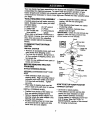
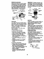
Owner's Manual
CRRFTSMflN"
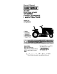
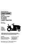
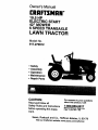
19.5 HP
ELECTRIC START
42" MOWER
6 SPEED TRANSAXLE
LAWN TRACTOR
Model No.
917.270912
•
•
•
•
Safety
Assembly
Operation
Maintenance
• Repair Parts
CAUTION:
Read and follow all
Safety Rules and Instructions
before operating this equipment.
For answers to your questions
about this product, Call:
1-800-659-5917
Sears Craftsmen Help Line
5 am - 5 pro, Mort - Sat
Seam, Roebuck and Co., Hoffman Estates, IL 60179
Visitour Craftsmanwebsite:www.sears.com/cmftsman
Warranty ...............................................
2
Safety Rules .........................................
2
Product Specifications .......................... 5
Assembly ..............................................
7
Operation ............................................
10
Maintenance Schedule ...................... 17
Maintenance ....................................... 17
Service and Adjustments .................... 21
Storage ............................................... 27
Troubleshooting .................................. 28
Repair Parts ........................................ 32
Parts Ordering ..................... Back Cover
LIMITED TWO YEAR WARRANTY ON CRAFTSMAN RIDING EQUIPMENT
For two (2) years from the date of purchase, if this Craftsman Riding Equipment is
maintained, lubricated and tuned up according to the instructions in the owner's
manual, Sears will repair or replace, free of charge, any parts found to be defective in
material or workmanship.
This Warranty does not cover:
• Expendable items which become worn during normal use, such as blades, spark
plugs, air cleaners, belts, etc.
• Tire replacement or repair caused by punctures from outside objects, such as nails,
thorns, stumps, or glass.
• Repairs necessary because of operator abuse, negligence, improper storage or
accident or the failure to maintain the equipment according to the instructions
contained in the owner's manual.
• Riding equipment used for commercial or rental purposes.
LIMITED 90 DAY WARRANTY ON BATTERY
For ninety (90) days from date of purchase, if any battery included with this riding
equipment proves defective in material or workmanship and our testing determines the
battery will not hold a charge, Sears will replace the battery at no charge. In-home
warranty service on your Craftsman riding equipment is available at no charge for 30
days from the date of purchase. Please contact your nearest service center. After 30
days from the date of purchase, warranty service is available by taking your Craftsman
riding equipment to your nearest Sears Service Center. (In-home warranty service will
still be available after 30 days from the date of purchase but a standard trip charge will
apply). This warranty applies only while this product is in the United States. This
Warranty gives you specific legal rights, and you may also have other rights which may
vary from state to state.
Seam, Roebuck and Co., D/817 WA, Hoffman Estates, IL 60179
• Be sure the area is clear of other
people before mowing. Stop machine if
anyone enters the area.
• Never carry passengers.
• Do not mow in reverse unless absolutely necessary. Always look down
and behind before and while backing.
• Be aware of the mower discharge
direction and do not point if at anyone.
Do not operate the mower without
either the entire grass catcher or the
guard in place.
• Slow down before turning.
IMPORTANT:
This cutting machine is
capable of amputating hands and feet
and throwing objects. Failure to observe
the following safety instructions could
result in serious injury or death.
GENERAL OPERATION
• Read, understand, and follow all
instructions in the manual and on the
machine before starting.
• Only allow responsible adults, who are
familiar with the instructions, to operate
the machine.
• Clear the area of objects such as rocks,
toys, wire, etc., which could be picked
up and thrown by the blade.
2
• Never leave a running machine
unattended. Always tum off blades, set
parking brake, stop engine, and remove
keys before dismounting.
• Turn off blades when not mowing.
• Stop engine before removing grass
catcher or unclogging chute.
• Mow only in daylight or good artificial
light.
• Do not operate the machine while
under the influence of alcohol or drugs.
• Watch for traffic when operating near or
crossing roadways.
• Use extra care when loading or
unloading the machine into a trailer or
truck.
• Data indicates that operators, age 60
years and above, are involved in a
large percentage of riding mowerrelated injuries. These operators should
evaluate their ability to operate the
riding mower safely enough to protect
themselves and others from serious
injury.
SLOPE OPERATION
Slopes are a major factor related to lossof-control and tipover accidents, which
can result in severe injury or death. All
slopes require extra caution. If you cannot
back up the slope or if you feel uneasy on
it, do not mow it.
DO:
• Mow up and down slopes, not across.
• Remove obstacles such as rocks, tree
limbs, etc.
• Watch tor holes, ruts, or bumps. Uneven
terrain could overturn the machine. Tall
grass can hide obstacles.
• Use slow speed. Choose a low gear so
that you will not have to stop or shift
while on the slope.
• Follow the manufacturer's recommendations for wheel weights or counterweights to improve stability.
• Use extra care with grass catchers or
other attachments. These can change
the stability of the machine.
• Keep all movement on the slopes slow
and gradual. Do not make sudden
changes in speed or direction.
• Avoid starting or stopping on a slope. If
tires lose traction, disengage the blades
and proceed slowly straight down the
slope.
DO NOT:
• Do not turn on slopes unless necessary, and then, turn slowly and gradual
ly downhill, if possible.
• Do not mow near drep-offs, ditches, or
embankments. The mower could
suddenly turn over if a wheel is over the
edge of a cliff or ditch, or if an edge
caves in.
• Do not mow on wet grass. Reduced
traction could cause sliding.
• Do nottry to stabilize the machine by
putting your foot on the ground.
• Do not use grass catcher on steep
slopes.
CHILDREN
Tragic accidents can occur if the operator
is not alert to the presence of children.
Children are often attracted to the
machine and the mowing activity. Never
assume that children will remain where
you last saw them.
• Keep children out of the mowing area
and under the watchful care of another
responsible adult.
• Be alert and tum machine off if children
enter the area.
• Before and when backing, look behind
and down for small children.
• Never carry children. They may fall off
and be seriously injured or interfere
with safe machine operation.
• Never allow children to operate the
machine.
• Use extra care when approaching blind
comers, shrubs, trees, or other objects
that may obscure vision.
SERVICE
• Use extra care in handling gasoline
and other fuels. They are flammable
and vapors are explosive.
Use only an approved container.
Never remove gas cap or add fuel
with the engine running. Allow
engine to cool before refueling. Do
not smoke.
Never refuel the machine indoors.
Never store the machine or fuel
container inside where there is an
open flame, such as a water heater.
• Never run a machine inside a closed
area.
3
• Keep nuts and bolts, especially blade
attachment bolts, tight and keep
equipment in good condition.
• Never tamper with safety devices.
Check their proper operation regulady.
• Keep machine free of grass, leaves, or
other debris build-up. Clean oil or fuel
spillage. Allow machine to cool before
stodng.
• Stop and inspect the equipment if you
stdke an object. Repair, if necessary,
before restarting.
• Never make adjustments or repairs with
the engine running.
• Be sure the area is clear of other
people before mowing. Stop machine if
anyone enters the area.
• Never carry passengers or children
even with the blades off.
• Do not mow in reverse unless absolutely necessary. Always look down
and behind before and while backing.
• Never carry children. They may fall off
and be seriously injured or interfere
with safe machine operation.
• Keep children out of the mowing area
and under the watchful care of another
responsible adult.
• Be alert and tum machine off if children
enter the area.
• Before and when backing, look behind
and down for small children.
• Mow up and down slopes (15 ° Max),
not across.
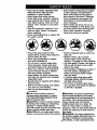
_Look for this symbol to point out
important safety precautions. It means
CAUTIONll! BECOMEAWARE!!! YOUR
_FETY IS INVOLVED.
CAUTION. In order to prevent accidental starting when setting up, transporting,
adjusting or making repairs always
disconnect spark plug wire and place wire
_i/L_re it cannot contact spark plug.
AUTION: Do not coast down a hill in
neutral, you may lose control of the tractor.
• Grass catcher components are subject
to wear, damage, and deterioration,
which could expose moving parts or
allow objects to be thrown. Frequently
check components and replace with
manufacturer's recommended pads,
when necessary.
• Mower blades are sharp and can cut.
Wrap the blade(s) or wear gloves, and
use extra caution when servicing them.
• Check brake operation frequently.
Adjust and service as required.
• Remove obstacles such as rocks, tree
limbs, etc.
• Watch for holes, ruts, or bumps.
Uneven terrain could overtum the
machine. Tall grass can hide obstacles.
• Use slow speed. Choose a low gear so
that you will not have to stop or shift
while on the slope.
• Avoid starting or Stoppingon a slope. If
tires lose traction, disengage the
blades and proceed slowly straight
down the slope.
• If machine stops while going uphill,
disengage blades, shift into reverse
and back down slowly.
• Do not turn on slopes unless necessary, and then, turn slowly and gradually downhill, if possible.
_CAUTION:
TOW 0nly the attachments
that are recommended by and comply
with specifications of the manUfacturer of
your tractor. Use common sense when
towing. Operate only at the lowest
possible speed when on a slope. Too
heavy of a load, while on a slope, is
dangerous. Tires can lose traction with the
ground and cause you to lose control of
Y_uWAr
tractoi'.
RNING" The engine exhaust from
this product contains chemicals known to
the State of Califomia to cause cancer,
4birth
defects, or other reproductive harm.
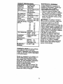
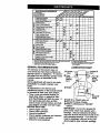
PRODUCT SPEClRCATIONS
3ASOLINE
3.5 GALLONS
CAPACITY
U NLEAD ED
_,NDTYPE:
REGULAR
OILTYPE
API-SF/SG/SH):
SAE 30 (ABOVE 32°F)
SAE 5W-30
(BELOW
OIL CAPACITY:
SPARK PLUG:
GAP: .030")
VALVE
CLEARANCE:
32°F)
3.0 PINTS
CHAMPION
OR J19LM
RJ19LM
INTAKE:
EXHAUST:
.004"-.006"
.007"-.009"
GROUND SPEED FORWARD:
I sT
(MPH):
2 N°
3 R°
4 TM
5 TM
6 TM
REVERSE:
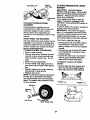
TIRE PRESSURE: FRONT:
A Sears Maintenance Agreement is
available on this product. Contact your
nearest Sears store for details.
CUSTOMER RESPONSIBILITIES
• Read and observe the safety rules.
• Follow a regular schedule in maintain
ing, caring for and using your tractor.
• Follow the instructions under =Malnte_
nance" and =Storage" sections of this
owner's manual.
_I_WARNING: This tractor is equipped
with an internal combustion engine and
should not be used on or near any
unimproved forest-covered, brushcovered or grass-covered land Unless th
engine's exhaust system is equipped wit.
a spark arrester meeting applicable local
or state laws (if any). If a spark arrester is
used, it should be maintained in effective
working order by the operator.
In the state of California the above is
1.2
1.5
2.3
3.5
4.8
5.4
1.5
14 PSi
10 PSI
3 AMPS BATTERY
5 AMPS
AMP/HR:
30
MiN. CCA: 240
CASE SIZE: U 1 R
through your nearest Sears Authorized
Service Center (See REPAIR PARTS
section of this manual).
i
BLADE BOLT
TORQUE:
AGREEMENT
required by law (Section 4442 of the
California Public Resources Code). Othe=
states may have similar laws. Federal
laws apply on federal lands. A spark
arrester for the muffler is available
REAR:
CHARGING
SYSTEM:
HEADLIGHTS
BATTERY:
MAINTENANCE
27--35 FT. LBS.
CONGRATULATIONS on your purchase
of a Craftsman Tractor. It has been
designed, engineered and manufactured
to give you the best possible dependabiUty and performance.
Should you experience any problem you
cannot easily remedy, please contact
your nearest Sears Authorized Service
Center. We have competent, well-trained
technicians and the proper tools to
service or repair this tractor.
Please read and retain this manual. The
instructions will enable you to assemble
and maintain your tractor properly. Always
observe the =SAFETY RULES'.
5
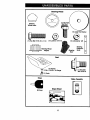
I
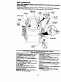
Steering Wheel
O
Stasdng
Wheel Insert
1
(1} large Flat Washer
(1) Hex Bolt 5/16-18 x 1-1/4
_
I1) Locknut 5/16-18
(1) Lockwasher 3/8
Steedng Wheel
_
,
Steering
Boot
Adapter
Extension
Steering
Shaft
,C
l
Seat
(1) Washer
17/32 x 1-3/16 x 12 Gauge
_(1)
(1} Shoulder
Bolt 5/16-18
Knob
Keys
Video Cassette
Slope Sheet
(2) Keys
6
C3
Your new tractor has been assembled at the factory with exception of those parts left
unassembled for shipping purposes. To ensure safe and proper operation of your
tractor all pads and hardware you assemble must be tightened securely. Use the
correct tools as necessary to insure proper tightness. Review the video cassette before
you begin.
TOOLS
REQUIRED
FOR ASSEMBLY
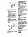
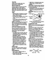
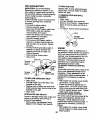
• Assemble large flat washer, 3/8 lock
washer, 3/8 hex bolt and tighten
A socket wrench set Will make assembly
securely.
easier. Standard wrench sizes you need
•
Snap steering wheel insert into center
are listed below.
of steering wheel.
(1) 9/16" wrench
(2) 1/2" wrench
•
Remove protective materials from
(1) Utility knife
(1) Pliers
tractor
hood and grill.
(1) 3/4" socket with
(1) Tire pressure
IMPORTANT:
Check for and remove any
drive ratchet
gauge
staples
in
skid
that
may puncture tires
When right or left hand is mentioned in
where tractor is to roll off skid.
this manual, it means, from your point of
view, when you are in the operating
Insert
position (seated behind the steering
wheel).
TO REMOVE TRACTOR FROM
_,/Lockwasher
CARTON
UNPACK
_
CARTON
• Remove all accessible loose parts and
parts boxes from shipping carton.
• Cut, from top to bottom, along lines on
all four comers of shipping carton, and
lay panels flat.
• Check for any additional loose parts or
boxes and remove.
Steering
Large Flat
_
Steering
Boot
Tabs
Wheel
Extension
Shaft
_'Adapter
BEFORE REMOVING TRACTOR
FROM SKID
_16
Locknut
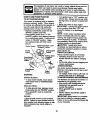
ATTACH STEERING WHEEL
5/16
Bolt
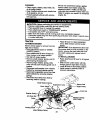
ASSEMBLE EXTENSION SHAFT AND
BOOT
• Slide extension shaft onto lower
steering shaft. Align mounting holes in
extension and lower shafts and install
5/16 hex bolt and Iocknut. Tighten
securely.
• Place tabs of steering boot over tab
slots in dash and push down to secure,
INSTALL STEERING
HOW TO SET UP YOUR TRACTOR
CONNECT BATTERY
WHEEL
Lift hood to raised position.
If this battery is put into service after
month and year indicated on label
(label located between terminals)
charge battery for minimum of one hour
at 6-10 amps. (See "BA'I-rERY"
in
MAINTENANCE
section of this manual
for charging instructions).
• Position front wheels of the tractor so
they are pointing straight forward.
• Remove steering wheel adapter from
steering wheel and slide adapter onto
steering shaft extension.
• Position steering wheel so cross bars
are horizontal (left to right) and slide
inside boot and onto adapter.
7
TO ROLL TRACTOR OFF SKID (See
Operation section for location and
function of controls)
o,
Label
• Press lift lever plunger and raise
attachment lift lever to its highest
position.
• Release parking brake by depressing
clutch/brake pedal.
• Place gearshift lever in neutral (N)
position.
• Roll tractor forward off skid.
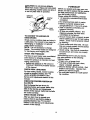
TO DRIVE TRACTOR OFF SKID
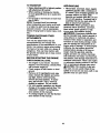
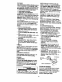
WARNING: Before starting, read, underINSTALL SEAT
stand and follow all instructions in the
Operation section of this manual. Be sure
Adjust seat before tightening adjustment
tractor is in a well-ventilated area. Be sure
knob.
the area in front of tractor is clear of other
• Remove adjustment knob and flat
people and objects.
washer securing seat to cardboard
• Be sure all the above assembly steps
packing and set aside for assembly of
have been completed.
seat to tractor,
• Check engine oil level arid fill fuel tank
• Pivot seat upward and remove from the
with gasoline.
cardboard packing. Remove the
• Sit on seat in operating position,
carboard packing and discard.
depress clutch/brake pedal and set the
• Place seat on seat pan and assemble
parking brake.
shoulder bolt. Tighten shoulder bolt
• Place gear shift lever in neutral (N)
securely.
position.
• Assemble adjustment knob and flat
• Press lift lever plunger and raise
washer loosely. Do not tighten;
attachment lift lever to its highest
• Lower seat into operating position and
sit on seat.
position.
• Slide seat until a comfortable position is • Start the engine. After engine has
started, move throttle control to idle
reached which allows you to press
position.
clutch_rake pedal all the way down.
• Depress clutch/brake pedal into full
• Get off seat without moving its adjusted
'BRAKE" position and hold. Move
position.
gearshift lever to 1st gear.
• Raise seat and tighten adjustment knob
•
Slowly release clutch/brake pedal and
securely.
Seat
slowly drive tractOroff skid.
• Apply brake to stop tractor, set parking
brake and place gearshift lever in
neutral position.
Shoulder
_
I
• Tum ignition key to "OFF" position.
Continue with the instructions that follow.
Seat Pan
÷°-"._.;,*
o- .....
Knob
NOTE: You may now roll or drive your
tractor off the skid. Follow the appropriate
instruction below to remove the tractor
from the skid,
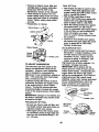
INSTALL MULCHER PLATE
(If prevlously removed)
• Raise and hold deflector shield in
upright position.
• Place front of mulcher plate over front of
mower deck opening and slide into
place, as shown.
• Hook front latch into hole on front of
mower d_ck.
• Hook rear latch into hole on back of
mower deck.
8
_CAUTION:
Do not remove deflector
shield from mower. Raise and hold shield
ttCHECKLIST
Before you operate and enjoy your new
tractor, we wish to assure that you receive
the best performance and satisfaction
from this quality product.
Deflector
Please review the following checklist:
,/ All assembly instructions have been
completed.
/ No remaining loose parts in carton.
,/Battery
is properly prepared and
charged.(Minimum
1 hour at 6 amps).
,/Seat
is adjusted comfortably and
Shield
_ate
Mulcher
HooksLatch
tightened securely.
,/All tires are propedy inflated. (For
shipping purposes, the tires were
ovefinfleted at the factory).
TO CONVERT TO BAGGING OR
,/Be sure mower deck is properly leveled
DISCHARGING
side-to-side/front-to-rear
for best cutting
results. (Tires must be propedy inflated
Simply remove mulcher plate and store in
a safe place. Your mower is now ready for
for leveling).
/
Check mower and drive belts. Be sure
discharging or installation of optional
they
are routed properly around pulleys
grass catcher accessory.
and
inside
all belt keepers.
NOTE: it is not necessary to change
blades. The mulcher blades are designed
/ Check wiring. See that all connections
are still secure and wires are propedy
for discharging and bagging also.
clamped.
CHECK TIRE PRESSURE
While learning how to use your tractor,
The tires on your tractor were overinflated
pay extra attention to the following
at the factory for shipping purposes.
important items:
Correct tire pressure is important for best
,/Engine
oil is at proper level.
cutting performance.
,( Fuel tank is filled with fresh, clean,
• Reduce tire pressure to PSI shown in
regular unleaded ,g.asoline.
=PRODUCT SPECIFICATIONS"
section
,/Become
familiar with all controls - their
of this manual.
location and function. Operate them
CHECK DECK LEVELNESS
before you start the engine.
For best cutting results, mower housing
,/Be sure brake system is in safe operatshould be properly leveled. See =TO
ing condition.
LEVEL MOWER HOUSING" in the
Service and Adjustments section of this
manual.
when attaching mulcher plate and allow it
to rest on plate while in operation.
CHECK FOR PROPER PosmoN OF
ALL BELTS
See the figures that are shown for
replacing motion and mower blade ddve
belts in the Service and Adjustments
section of this manual. Verify that the belts
are routed correctly.
CHECK BRAKE SYSTEM
After you learn how to operate your
tractor, check to see that the brake is
properly adjusted, See =TO ADJUST
BRAKE" in the Service and Adjustments
section of this manual.
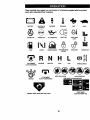
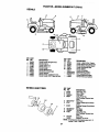
These symbols may appear on your tractor or in literature supplied with the product.
Leam and understand their meaning.
BATTERY
CAUTION OR
WARNING
REVERSE
FORWARD
FAST
SLOW
ENGINE ON
ENGINE OFF
OIL PRESSURE
LIGHTS ON
OVER TEMP
LIGHT
FUEL
CHOKE
MOWER HEIGHT
PARKING BRAKE
LOCKED
UNLOCKED
MOWER LIFT
H L
ATTACHMENT
CLUTCH ENGAGED
REVERSE
NEUTRAL
ATTACHMENT
IGNITION
HIGH
LOW
KEEP AREA CLEAR
CLUTCH DISENGAGED
PARKING BRAKE
SLOPE HAZARDS
(SEE SAFETY RULES SECTION)
FREE WHEEL
(AutomaticModelsonly)
DANGER, KEEP HANDS AND FEET AWAY
10
KNOWYOURTRACTOR
READ THIS OWNER'S
YOUR TRACTOR
MANUALAND
SAFETY
RULES BEFORE
OPERATING
Compare the illustrations with your tractor to _amiliarize yoursel_with the locations of
various controls and adjustments. Save this manual for future reference.
Attachment
Clutch Lever
Light
Ignition
Switch
Ammeter
Choke Control
Lift Lever
Throttle
Attachment
Lift Lever
Control _
Clutch/
Brake
Pedal
Height
Adjustmenl
Indicator
Parking Brake
Gearshift
Lever
I
Our tractors conform to the safety standards of the American
National Standards Institute.
I
ATTACHMENT
CLUTCH
LEVER:
Used
GEARSHIFT LEVER: Selects the speed
and direction of tractor.
ATTACHMENT LIFT LEVER: Usedto
raise, lower, and adjust the mower deck
or other attachments mounted to your
tractor.
LIFT LEVER PLUNGER: Used to release
attachment lift lever when changing its
position.
IGNITION SWITCH: Used for starting and
stopping the engine.
AMMETER: Indicates battery charging
(+) or discharging (-).
to engage the mower blades, or other
attachments mounted to your tractor.
LIGHT SWITCH: "rums the headlights on
and off.
THROTTLE
CONTROL:
Used for starting
and controlling engine speed.
CHOKE CONTROL:
Used when starting
a cold engine.
CLUTCH/BRAKE
PEDAL:
Used for
declutching and braking the tractor and
starting the engine.
PARKING BRAKE: Locks clutch/brake
pedal into the brake position.
11
The operation of any tractor can result in foreign objects thrown into the
eyes, which can result in severe eye damage. Always wear safety
glasses or eye shields while operating your tractor or performing any
adjustments or repairs. We recommend a wide vision safety mask over
spectacles, or standard safety glasses.
HOW TO USE YOUR TRACTOR
TO SET PARKING BRAKE
Your tractor is equipped with an operator
presence sensing switch. When engine
is running, any attempt by the operator to
leave the seat without first setting the
parking brake will shut off the engine.
• Depress clutch/brake pedal into full
"BRAKE" position and hold.
• Place parking brake lever in =ENGAGED" position and release pressure
from clutch/brake pedal. Pedal should
remain in =BRAKE" position. Make
sure parking brake will hold tractor
secure.
Choke Control AttachmentClutchLever
•Engaged"Position
Throttle
Control
"Disengaged"
Poei_on
Parking Brake
Position
'Disengaged"
Position
Lever
"Brake"
Position
STOPPING
MOWER BLADES • To stop mower blades, move attachment clutch lever to "DISENGAGED"
position.
GROUND DRIVE • To stop ground drive, depress clutch/
brake pedal into full "BRAKE" position.
• Move gearshift lever to neutral (N)
position.
ENGINE • Move throttle control to slow position.
NOTE: Failure to move throttle control to
slow position and allowing engine to idle
before stopping may cause engine to
"backfire".
•Tum ignition kay to =OFF" position and
remove key. Always remove key when
leaving tractor to prevent unauthorized
use,
• Never use choke to stop engine.
IMPORTANT: Leaving the ignition switch
in any position other than =OFF" will
cause the battery to be discharged,
(dead).
NOTE: Under certain conditions when
tractor is standing idle with the engine
running, hot engine exhaust gases may
cause =browning" of grass. To eliminate
this possibility,always stop engine when
stopping tractor on grass areas.
_CAUTION:
Always stop tractor
completely, as described above, before
leaving the operator's position; to empty
grass catcher, etc.
THROTTLE CONTROL
Always operate engine at full throttle.
• Operating engine at less than full
throttle reduces the battery charging
rate,
• Full throttle offers the best bagging and
mower performance.
CHOKE CONTROL
Use choke control whenever you are
starting a cold engine. Do not use to start
a warm engine.
• To engage choke control, pull knob out.
Slowly push knob in to disengage.
TO MOVE FORWARD AND BACKWARD
The direction and speed of movement is
controlled by the gearshift lever.
• Start tractor with clutch/brake pedal
depressed and gearshift lever in
neutral (N) position.
• Move gearshift lever to desired
position.
• Slowly release clutch/brake pedal to
start movement.
IMPORTANT: Bdng tractor to a complete
stop before shifting or changing gears.
Failure to do so will shorten the useful life
of your transaxle.
12
TO ADJUST MOWER cuTr|NG
HEIGHT
TO OPERATE
The position of the attachment lift lever
determines the cutting height.
• Grasp lift lever.
• Press plunger with thumb and move
lever to desired position.
The cutting height range is approximately 1-1/2 to 4". The heights are
measured from the ground to the blade tip
with the engine not running. These
heights are approximate and may vary
depending upon soil conditions, height of
grass and types of grass being mowed.
• The average lawn should be cut to
approximately 2-1/2 inches during the
cool season and to over 3 inches
during hot months. For healthier and
better looking lawns, mow often and
after moderate growth.
• For best cutting performance, grass
over 6 inches in height should be
mowed twice. Make the first cut
relatively high; the second to desired
height.
TO ADJUST GAUGE WHEELS
Gauge wheels are pi'opedy adjusted
when they are slightly off the ground
when mower is at the desired cutting
height in operating position. Gauge
wheels then keep the deck in proper
position to help prevent scalping in most
terrain conditions.
* Adjust gauge wheels with tractor on a
flat level surface.
. Adjust mower to desired cutting height
(See "TO ADJUST MOWER CUTTING
HEIGHT" in the Operation section of this
manual).
• With mower in desired height of cut
position, gauge wheels should be
assembled so they are slightly off the
ground. Install gauge wheel in appropriate hole with shoulder bolt, 3/8
washer, and 3/8-16 lecknut and tighten
secure_.
• Repeat for opposite side installing
gauge wheel in same adjustment hole.
Bracket
Your tractor is equipped with an operet(
presence sensing switch. Any attempt b,
the operator to leave the seat with the
engine running and the attachment clutc
engaged will shut off the engine.
• Select desired height of cut.
• Start mower blades by engaging
attachment clutch control.
• TO STOP MOWER BLADES - disengage attachment
Gauge Wheel
clutch control.
ACAUTION:
Do not operate the mower
without either the entire grass catcner, o
mowers so equipped, or the deflector
shield in place.
Attachment Clutch
Lever
Position
Position
Attachment Lift Lev
High Position
Low
Position
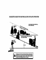
TO OPERATE ON HILLS
_CAUTION:
Do not drive up or down
hills with slopes greater than 15° and do
not drive across any slope. A slope guide
at the back of your manual is provided for
your use.
• Choose the slowest speed before
starting up or down hills.
• Avoid stopping or changing speed on
hills.
• If slowing is necessary, move throttle
control lever to slower position.
• If stopping is absolutely necessary,
push clutch/brake pedal quickly to
brake position and engage parking
brake.
• Move gearshift lever to 1st gear. Be
sure you have allowed room for tractor
to roll slightly as you restart movement.
• To restart movement, slowly release
parking brake and clutch/brake pedal.
• Make all turns slowly.
3/8-16 Locknut.
3/8
MOWER
Shoulder
13
TO TRANSPORT
• Raise attachment lift to highest position
with attachment lift control.
• When pushing or towing your tractor,
be sure gearshift lever is in neutral (N)
position.
• Do not push or tow tractor at more than
five (5) MPH.
NOTE: To protect hood from damage
when transporting your tractor on a truck
or a trailer, be sure hood is closed and
secured to tractor. Use an appropriate
means of tying hood to tractor (rope, cord,
etc.).
TOWING CARTS AND OTHER
A'I-I'ACHMENTS
Tow only the attachments that are
recommended by and comply with
specifications of the manufacturer of your
tractor. Use common sense when towing.
Too heavy of a load, while on a slope, is
dangerous. Tires can lose traction with
the ground and cause you to lose control
of your tractor.
BEFORE STARTING THE ENGINE
CHECK ENGINE OIL LEVEL
• The engine in your tractor has been
shipped, from the factory, already filled
with summer weight oil.
• Check engine oil with tractor on level
ground.
• Remove oil fill cap/dipstick and wipe
dean, relnsert the dipstick and screw
cap tight, wait for a few seconds,
remove and read oil level. If necessary, add oil until =FULL" mark on
dipstick is reached. Do not overfill.
• For cold weather operation you should
change oil for easier starting (See =OIL
VISCOSITY CHART" in the Maintenance section of this manual).
• To change engine oil, see the Maintenance section in this manual.
ADD GASOUNE
• Fill fuel tank. Use fresh, clean, regular
unleaded gasoline with a minimum of
87 octane. (Use of leaded gasoline will
increase carbon and lead oxide
deposits and reduce valve life). Do not
mix oil with gasoline. Purchase fuel in
quantities that can be used within 30
days to assure fuel freshness.
IMPORTANT: When operating in temperatures below 32°F(0°C), use fresh,
clean winter grade gasoline to help
insure good cold weather starting.
_WARNING:
Experience indicates that
alcohol blended fuels (called gasohol or
using ethanol or methanol) can attract
moisture which leads to separation and
formation of acids during storage. Acidic
gas can damage the fuel system of an
engine while in storage. To avoid engine
problems, the fuel system should be
emptied before storage of 30 days or
longer. Drain the gas tank, start the
engine and let it run until the fuel lines
and carburetor are empty. Use fresh fuel
next season. See Storage Instructionsfor
additional information. Never use engine
or carburetor cleaner products in the fuel
tank or permanent damage may occur.
ACAUTION: Fill to bottom of gas tank
filler neck. Do not overfill. Wipe off any
spilled oil or fuel. Do not store, spill or use
gasoline near an open flame.
14
TO START
ENGINE
When starting the engine for the first time
or if the engine has run out of fuel, it will
take extra cranking time to move fuel from
the tank to the engine.
• Sit on seat in operating position,
depress clutch/brake pedal and set
parking brake.
• Place gear shift lever in neutral (N)
position.
• Move attachment clutch to =DISENGAGED" position.
• Move throttle control to fast position
• Pull choke control out for a cold engine
start attempt. For a warm engine start
attempt the choke control may not be
needed.
NOTE: Before starting, read the warm and
cold starting procedures below.
• Insert key into ignition and turn key
clockwise to "START" position and
release key as soon as engine starts.
Do not run starter continuously for more
than fifteen seconds per minute. If the
engine does not start after several
attempts, push choke control in, wait a
few minutes and try again. If engine still
does not start, pull the choke control
out and retry.
WARM WEATHER
ABOVE)
STARTING
COLD WEATHER
BELOW)
STARTING
(50 ° F ANC
• When engine starts, slowly push choke
control in until the engine begins to rur
smoothly. Continue to push the choke
• control in small steps allowing the
engine to accept small changes in
speed and load, until the choke control
is fully in. If the engine starts to run
roughly, pull the choke control out
slightly for a few seconds and then
continue to push the control in slowly.
This may require an engine warm-up
period from several seconds to several
minutes, depending on the temperature.
• The attachments can be used during
the engine warm-up period and may
require the choke control be pulled out
slightly.
NOTE: A high altitude (above 3000 feet)
or in cold temperatures (below 32 F) the
carburetor fuel mixture may need to be
adjusted for best engine performance.
See "1"O ADJUST CARBURETOR"
in the
Service and Adjustments
manual.
(50 ° FAND
• When engine starts, slowly push choke
control in until the engine begins to run
smoothly. If the engine starts to run
roughly, pull the choke control out
slightly for a few seconds and then
continue to push the control in slowly.
• The attachments and ground drive can
now be used. If the engine does not
accept the load, restart the engine and
allow it to warm up for one minute
using the choke as described above.
15
section of this
MOWINGIIPS
MULCHING
• Mower should be properly leveled for
best mowing performance.
See 'TO
LEVEL MOWER HOUSING" in the
IMPORTANT:
For best performance,
keep mower housing free of built-up grass
and trash. Clean after each use.
• The special mulching blade will recut
the grass clippings many times and
reduce them in size so that as they fall
onto the lawn they will disperse into the
grass and not be noticed. Also, the
mulched grass will biodegrade quickly
to provide nutdents for the lawn.
Always mulch with your highest engine
(blade) speed as this will provide the
best recutting action of the blades.
• Avoid cutting your lawn when it is wet.
Wet grass tends to form clumps and
interferes with the mulching action. The
best time to mow your lawn is the sady
afternoon. At this time the grass has
dried and the newly cut area will not be
exposed to the direct sun.
• For best results, adjust the mower
cutting height so that the mower cuts off
only the top one-third of the grass
blades. For extremely heavy mulching,
reduce your width of cut on each pass
and mow slowly.
• Certain types of gress and grass
conditions may require that an area be
mulched a second time to completely
hide the clippings. When doing a
second cut, mow across or perpendicular to the first cut path.
• Change your cutting pattern from week
to week. Mow north to south one week
Service and Adjustments section of this
manual;
• The left hand side of mower should be
used for trimming.
• Drive so that clippings are discharged
onto the area that has been cut. Have
the cut area to the right of the machine.
This will result in a more even distribution of Clippings and more uniform
cutting.
• When mowing large areas, start by
turning to the right so that clippings will
discharge away from shrubs, fences,
driveways, etc. After one or two
rounds,
mow in the opposite direction making
left hand tums until finished
• If grass is extremely tall, it should be
mowed twice to reduce load and
possible fire hazard from dried clippings. Make first cut relatively high; the
second to the desired height.
• Do not mow grass when it is wet. Wet
grass will plug mower and leave
undesirable clumps. Allow grass todry
before mowing.
• Always operate engine at full throttle
when mowing to assure better mowing
performance and proper discharge of
matedal. Regulate ground speed by
selecting a low enough gear to give the
mower the best cutting performance as
well as the quality of cut desired.
• When operating attachments, select a
ground speed that will suit the terrain
and give bast performance of the
attachment being used.
•
MOWING
TIPS
then change to east to west the next
week. This will help prevent matting
and graining of the lawn.
J
16
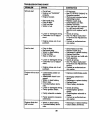
MAINTENANCE SCHEDULE
Ch_ckOperJtorPrnsenceand
.,,_',_@"J._.,_./_._/_
T tmdo_Sy_m_
V'
R c_o_io,;.o+._:,,_,-,
IV'
V',
A
T
SI_I_o_VRepl_e MOwer Blad_s
Lu_DdcationCl'mrl
_4
0
C_eckBatter/Level
l_e
R
C.=n
_
Battery and Tonnlnals
l_
Adjust Blade Belt(s) Teflon
!_#s
AdjustMoltonDriveBalt(s) Tension
Ks
Check Engine 0_1Level
_
li_
_
Air Fgter
_:_
ann
Air Screen
I_'=
N
V'
ll_
CheckTransaxleCooling
E
N
._'"_'_,._.
ReplaceOilFilter(If _Idl_
Qean EngineCooing Fins
._.=
R_=e S_rkP_
_,2 t/
Rep!a_e Air Filter P&per Cartridge
_2
Replace Fuel Filter
1 - ChMIg_ morn oiler when eCMMklg Lmdl_I helvy k_d o_kl hlgll Irnbkml temPer_weL
2 - S_n_ mo_e 04_mwtt4m Op_l_g In dl_ or d_lMlf¢@41d11_.
4 - I_ohice b_4Hi morn _dten _
GENERAL
mo_ng In ur_y
_d,
S - If e_oed
Wth Iid_ltlb_
Wstem.
_ - _tot _li_ik'ld il _lpp41d k_f_ p_ail_t_n_o-_ fa_ b_11 f_.
DOn_4_l_9ht+,n,
LUBRICATION CHART
RECOMMENDATIONS
The warranty on this tractor does not
_) Spindle
- Spindle _)
cover items that have been subjected to
Zerk
Zerk
operator abuse or negligence. To receive
_)
full value from the warranty, operator must (_ Front
Wheel
maintain tractor as instructed in this
Bearing
-_
Beadng
manual.
Zerk
Zerk
Some adjustments will need to be made
periodically to properly maintain your
tractor.
All adjustments in the Service and
Adjustments section of this manual should
be checked at least once each season.
• Once a year you should replace the
_-"
Gearshlf
spark plug, clean or replace air filter,
.... *
'---J
Pivots
and check blades and belts for wear. A Q)SAE 30 or 10w30 motor oil
new spark plug and clean air filter
_) General Purpose Grease
assure proper air-fuel mixture and help
_) Refer to Maintenance =ENGINE"
your engine run better and last longer.
Section
BEFORE EACH USE
IMPORTANT: Do not oll or grease the
• Check engine oil level.
pivot points which have special nylon
• Check brake operation.
bearings. Viscous lubricants will attract
• Check tire pressure.
dust and dirt that will shorten the life of the
• Check operator presence and interlock, self-lubricatieg besdngs. If you feel they
systems for proper operation.
must be lubricated, use only a dry, pow• Check for loose fasteners.
dered graphite type lubricant sparingly.
17
Always observe safety rules when
peflorming any maintenance.
BRAKE
OPERATION
If tractor requires more than six (6) feet
stopping distance at high speed in
highest gear, then brake must be adjusted. (See "TO ADJUST BRAKE" in the
Service and Adjustments section of this
manual).
TIRES
• Maintain proper air pressure in all tires
(See "PRODUCT SPECIFiCATiONS"
section of this manual).
• Keep tires free of gasoline, oil, or insect
control chemicals which can harm
rubber.
• Avoid stumps, stones, deep ruts, sharp
objects and other hazards that may
cause tire damage.
NOTE: To seal tire punctures and prevent
flat tires due to slow leaks, tire sealant
may be purchased from your local parts
dealer. Tire sealant also prevents tire dry
rot and corrosion.
OPERATOR
PRESENCE
SYSTEM
Be surethat operator presence and
interlock systems are working propedy. If
your tractor does not function as described below, repair the problem
immediately.
• The engine should not start unless the
clutch/brake pedal is fully depressed
and attachment clutch control is in the
disengaged
position.
• When the engine is running, any
attempt by the operator to leave the
seat without first setting the parking
brake should shut off the engine.
• When the engine is running and the
attachment clutch is engaged, any
attempt by the operator to leave the
seat should shut off the engine.
• The attachment clutch should never
operate unless the operator is in the
seat.
BLADE CARE
• Install new or resharpened blade with
trailing edge up towards deck as
shown.
IMPORTANT:
To ensure proper assembly,
center hole isn blade must align with star
on mandrel assembly.
• Reassemble hex bolt, lock washer and
flat washer in exact order as shown.
• Tighten bolt securely (27-35 Ft. Lbs.
torque).
IMPORTANT:
Blade bolt is Grade 8 heat
treated.
Trailing
Mandrel Assembly
Blade Center
Hole
Ftst Washer
Lock
_'-Hex
Bolt
°A Grade 8 heat treated bolt can be identified
by six lines on the bolt head.
TO SHARPEN
BLADE
NOTE: We do not recommend sharpening
blade, but if you do, be sure the blade is
balanced.
Care should be taken to keep the blade
balanced. An unbalanced blade will
cause excessive vibration and eventual
damage to mower and engine.
• The blade can be sharpened with a file
or on a grinding wheel. Do not attempt
to sharpen while it is on the mower.
• To check blade balance, you will need
a 5/8" diameter steel belt, pin, or a cone
balancsr. (When using a cone balancer, follow the instructions supplied
with balancer).
NOTE: Do not use a nail for balancing
blade. The lobes of the center hole may
appear to be centered, but are not.
• Slide blade onto an unthreaded portion
of the steel bolt or pin and hold the bolt
or pin parallel with the ground. If blade
is balanced, it should remain in a
horizontal position. If either end of the
blade moves downward, sharpen the
heavy end until the blade is balanced.
For best results mower blades must be
kept sharp. Replace bent or damaged
blades.
BLADE REMOVAL
5/8" BoR
or Pin _.Blade
• Raise mower to highest position to
allow access to blades.
• Remove hex belt, lock washer and flat
washer secudng
Up
Center Hole
blade.
18
BATTERY
Your tractor has a battery charging system
which is sufficient for normal use, However, pedodic charging of the battery with
an automotive charger will extend its life.
• Keep battery and terminals clean.
• Keep battery bolls tight.
• Keep small vent holes open.
• Recharge at 6-10 amperes for 1 hour.
NOTE: The original equipment battery on
your tractor is maintenance free. Do not
attempt to open or remove caps or covers.
Adding or checking level of electrolyte is
not necessary.
TO CLEAN BATTERY AND TERMINALS
Corrosion and dirt on the battery and
terminals can cause the battery to "leak"
power.
• Remove terminal guard.
• Disconnect BLACK battery cable first
then RED battery cable and remove
battery from tractor.
• Rinse the battery with plain water and
dry.
• Clean terminals and battery cable ends
with wire brush until bright.
• Coat terminals with grease or petroleum jelly.
• Reinstall battery (See "REPLACING
BATTERY" in the SERVICE AND
ADJUSTMENTS section of this manual).
V-BELTS
Check V-belts for deterioration and wear
after 100 hours of operation and replace
if necessary. The belts are not adjustable.
Replace belts if they begin to slip from
wear.
TRANSAXLE COOLING
Keep transaxle free from build-up of dirt
and chaff which can restrict cooling.
ENGINE
LUBRICATION
Only use high quality detergent oil rated
with API service classification SF, SG or
SH. Select the oil's SAE viscosity grade
according to your expected operating
temperature.
SAE VISCO_I_
NOTE: Although mulli-viscosity oils
(5W30, 10W30 etc.) improve starting in
cold weather, these mulli-viscosity oils
will result in increased oil consumption
when used above 32°F. Check your
engine oil level more frequently to avoid
possible engine damage from running
low on oil.
Change the oil after every 25 hours of
operation or at least once a year if the
tractor is not used for 25 hours in one
year.
Check the crankcase oil level before
starting the engine and after each eight
(8) hours of operation. Tighten oil fill cap/
dipstick securely each time you check th_
oil level.
TO CHANGE
ENGINE
OIL
Determine temperature
range expected
before oil change. All oil must meet API
service classification
SF, SG or SH.
• Be sure tractor is on level surface.
• Oil will drain more freely when warm.
• Catch oil in a suitable container.
• Remove oil fill cap/dipstick. Be careful
not to allow dirt to enter the engine
when changing oil.
• Remove drain plug.
• After oil has drained completely,
replace oil drain plug and tighten
securely.
• Refill engine with oil through oil fill
dipstick tube. Pour slowly. Do not
overfill. For approximate
capacity see
"PRODUCT SPECIFICATIONS"
section
of this manual.
• Use gauge on oil fill cap/dipstick for
checking level. Be sure dipstick cap is
tightened securely for accurate
reading. Keep oil at "FULL" line on
dipstick,
Air Screen
011Drain..........=
_
/__._
Plug
_..
Oil Fill Cap/Dipstick /
CLEAN
_y_
AIR SCREEN
GRADES
-20"
-20*
-10"
0"
10"
TEMPERATURE RANGE ANTIQ PATED BEFORE NEXT OIL CHNdGE
Air screen must be kept free of dirt and
chaff to prevent engine damage from
overheating. Clean with a wire brush or
compressed air to remove dirt and
stubborn dded gum fibers.
19
ENGINE COOLING RNS
Remove any dust, dirt or oil from engine
cooling fins to prevent engine damage
from overheating. Air guide covers must
be removed. Remove side panels and
hood (See "TO REMOVE HOOD AND
GRILL ASSEMBLY" in the Service and
Adjustments section of this manual).
Top Air Guide
C°VE_gine COO_"
IMPORTANT: Petroleum solvents, such
as kerosene, are not to be used to clean
the cartridge. They may cause detedoration of the cartddge. Do not oil cartridge.
Do not use pressudzed air to clean or dry
cartddge.
Cover
Knob
Wing Nut
Cartridge
Plate
Foam
Pre-Cleaner
Cartridge
Cover
AirScre_
(Both
Bides)
MUFFLER
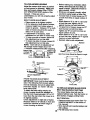
AIR FILTER
Your engine will not run propedy using a
dirty air filter. Clean the foam pre-clsaner
after every 25 hours of operation or every
season. Service paper cartridge every
100 hours of operation or every season,
whichever occurs first.
Service air cleaner more often under
dusty conditions.
• Remove knob(s) and cover.
TO SERVICE PRE-CLEANER
• Slide foam pre-cleaner off cartridge.
• Wash it in liquid detergent and water.
• Squeeze it dry in a clean cloth.
• Saturate it in engine oil. Wrap it in
clean, absorbent cloth and squeeze to
remove excess oil.
• If very dirty or damaged, replace precleaner.
• Reinstall pre-cleaner over cartridge.
• Reinstall cover and secure with
knob(s).
TO SERVICE CARTRIDGE
• Remove wing nuts and cartridge plate.
• Carefully remove cartridge to prevent
debds from entedng carburetor.
• Clean cartridge by tapping gently on flat
surface. If very dirty or damaged,
replace cartridge.
• Reinstall cartridge plate, wing nuts,
precleaner, cover and secure with
knob(s).
inspect and replace corroded muffler and
spark arrester (if equipped) as it could
create a fire hazard and/or damage.
SPARK PLUGS
Replace spark plugs at the beginning of
each mowing season or alter every 100
hours of operation, whichever occurs first.
Spark plug type and gap setting are
shown in "PRODUCT SPECIFICATIONS"
section of this manual.
IN-LINE FUEL FILTER
The fuel filter should be replaced once
each season. If fuel filter becOmes
clogged, obstructing fuel flow to carburetor, replacement is required.
• With engine cool, remove filter and plug
fuel line sections,
• Place new fuel filter in position in fuel
line with arrow pointing towards
carburetor.
• Be sure there are no fuel line leaks and
clamps are propedy positioned.
• Immediately wipe up any spilled
gasoline;
2O
CLEANING
• Clean engine, battery, seat, finish, etc.
of ell foreign matter.
• Keep finished surfaces and wheels free
of all gasoline, oil, etc.
• Protect painted surfaces with automotive type wax.
We do not recommend using a garden
hose to clean your tractor unless the
electrical system, muffler, air filter and
carburetor are covered to keep water out.
Water in engine can result in a shortened
engine life.
ACAUTION:
Before performing any service or adjustments:
• Depress clutcWbrake pedal fully and set parking brake.
• Place gearshift lever in neutral (N) position.
• Place attachment clutch in =DISENGAGED"
position.
•Tum
ignition key =OFF" and remove key.
• Make sure the blades and all moving parts have completely stopped.
• Disconnect spark plug wire from spark plug and place wire where it cannot come
in contact with plug.
TRACTOR
• Raise lift lever to raise suspension
arms. Slide mower out from under
tractor.
IMPORTANT: If an attachment other than
the mower deck is to be mounted on the
tractor, remove the front links and hook
the clutch spring onto square hole in
frame.
TO INSTALL MOWER
TO REMOVE MOWER
Mower will be easier to remove from the
right side of tractor.
• Place attachment clutch in =DISEN•
•
•
•
GAGED" position.
Move attachment lift lever forward to
lower mower to its lowest position.
Roll belt off engine pulley.
Remove small retainer spring, and lift
clutch spring off pulley bolt.
Remove large retainer spring, slide
collar off and push housing guide out of
bracket.
• Raise attachment lift lever to its highest
position.
• Slide mower under tractor with discharge guard to right side of tractor.
• Lower lift lever to its lowest position.
• Install mower in reverse order of
removal instructions.
• Disconnect anti-swaybar
from chassis
bracket by removing retainer spring.
• Disconnect suspension arms from rear
deck brackets by removing retainer
spdngs.
• Disconnect front links from deck by
removing retainer spdngs.
Small Retainer
Suspension Arms
; J"':"_-
Square Hole
Engine Pulley
Clutch
Retainer
AnU-Swa_
Springs
(Both Sides)
Housing Guide
Urge
;prig
21
TO LEVEL MOWER HOUSING
Adjust the mower while tractor is parked
on level ground or ddveway. Make sure
tires are propody inflated (See =PRODUCT SPECIFICATIONS" section of this
manual). If tiros are over or
undednflated, you will not propedy adjust
your mower.
SIDE-TO-SIDE ADJUSTMENT
• RaLse mower to its highest position.
• At the midpoint of both sides of mower,
measure height from bottom edge of
mower to ground. Distance "A" on both
sides of mower should be the same or
within I/4" of each other.
• If adjustment is necessary, make
adjustment on one side of mower only.
• To raise one side of mower, tighten lift
link adjustment nut on that side.
• To lower one side of mower, loosen lift
link adjustment nut on that side.
NOTE: Each full tum of adjustment nut
will change mower height about 1/8".
• Recheck measurements after adjusting.
Bottom Edge___ _
of Mowerto_
_t_[-------lL_
G r°und X_._ _._
_
• Before making any necessary adjustments, check that both front links are
equal in length. Both links should be
approximately 10-3/8".
• If links are not equal in length, adjust
one link to same length as other link.
• To lower front of mower loosen nut "E"
on both front links an equal number of
tums.
• When distance =D" is 1/8" to 1/2" lower
at front than roar, tighten nuts =F"
against trunnion on both front links.
• To raise front of mower, loosen nut =F"
from trunnion on both front links.
Tighten nut "E" on both front links an
equal number of tums.
• When distance =D" is 1/8" to 1/2" lower
at front than roar, tighten nut =F" against
trunnion on both front links.
• Recheck side-to-side adjustment.
Mandrel
Bottom Edge
\of Mowerto
_ .._0=und
Both Front Links Should be Equal in Length
=_oh_ Suspensi°n
Nut =E"
Nut "F'_
Nut
FRONT-TO-BACK
ADJUSTMENT
IMPORTANT:
Deck must be level side-toside. If the following front-to-beck adjustment is necessary, be sure to adjust both
front links equally so mower will stay
level side-to-side.
To bbtain the best cutting results, the
moWer housing should be adjusted so
that the front is approximately 1/8" to 112"
lower than the roar when the mower is in
Tmrmion f
Front Links
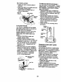
TO REPLACE MOWER BLADE DRIVE
BELT (See lUustration Next Page)
The mower blade drive belt may he
replaced without tools. Park the tractor on
level surface. Engage parking brake.
BELT REMOVALits highest position.
Check adjustment on right side of tractor.
• Remove mower from tractor (See ='1"O
Measure distance UD" directly in front and
REMOVE MOWER" in this section of
behind the mandrel at bottom edge of
this manual).
mower housing as shown.
• Work belt off both mandrel pulleys and
idler pulleys.
•
22 Pull belt away from mower.
BELTINSTALLATION -
TO REPLACE
• Install new belt in reverse order of
removal.
• Make sure belt is in all pulley grooves
and inside all belt guides.
• Install mower in reverse order of
removal instructions.
Park the tractor on level surface. Engage
parking brake. For assistance, there is a
belt installation guide decal on bottom
side of left footrest.
• Remove mower (See =TO REMOVE
MOWER" in this section of this manual./
• Remove belt from stationary idler and
clutching idler.
• Pull belt slack toward rear of tractor.
Mandrel
Idler Pulleys
MOTION
DRIVE BELT
Remove belt upwards from transaxle
pulley by deflecting belt keepers.
• Pull belt toward front of tractor and
remove downwards from around
engine pulley.
• Install new belt by reversing above
procedure.
TO ADJUST BRAKE
Your tractor is equipped with an adjustable brake system which is mounted on
the right side of the transaxle.
{f tractor requires more than six (6) feet
stopping distance at high speed in
highest gear, then brake must be adjusted.
• Depress clutch/brake pedal and
engage parking brake.
• Measure distance between brake
operating arm and nut =A" on brake rod.
• If distance is other than 1-112", loosen
jam nut and turn nut "A" until distance
becomes 1-1/2". Retighten jam nut
against nut "A".
• Road test tractor for proper stopping
distance as stated above. Readjust if
necessary. If stopping distance is still
greater than six (6) feet in highest gear,
further maintenance is necessary.
Contact your nearest authorized
service center/department.
With Parking Brake
"Engaged"
Nut 'A'
/am
O_Operating
Nut
Engine,
Pulley
Clutching
Idler
Stationary f
Idler
Transaxle
Pulley
TRANSAXLE GEAR SHIFT LEVER
ADJUSTMENT
The transaxla should be in neutral when
the gear shift lever is in neutral (N) (lock
gate) position. The adjustment is preset at
the factory; however, if adjustment is
needed, proceed as follows:
• Make sure transaxle is in neutral (N).
NOTE: When the tractor rear wheels
move freely, the transaxle is in neutral.
• Loosen adjustment bolt in front of the
right rear wheel.
• Position the gear shift lever in the
neutral (N) position.
• Tighten adjustment bolt securely.
NOTE: If additional clearance is needed
to get to adjustment bolt, move mower
deck height to the lowest position.
Arm
23
Gearshift Lever
Neutral
Lock Gate
/
TO ADJUST
ALIGNMENT
Adjustment
STEERING
WHEEL
If steering wheel crossbars are not
horizontal (left to right) when wheels are
positioned straight forward, remove
steering wheel and reassemble per
instructions in the Assembly section of this
manual,
FRONT WHEEL TOE-IN/CAMBER
The front wheel toe-in and camber are not
adjustable on your tractor. If damage has
occurred to affect the front wheel toe-in or
camber, contact your nearest authorized
service center/department,
TO REMOVE WHEEL FOR REPAIRS
• Block up axle securely.
• Remove axle cover, retaining ring and
washers to allow wheel removal (rear
wheel contains a square key - Do not
lose).
• Repair tire and reassemble.
• On rear wheels only: align grooves in
rear wheel hub and axle. Insert square
key.
• Replace washers and snap retaining
ring securely in axle groove.
• Replace axle cover.
NOTE: To seal tire punctures and prevent
flat tires due to slow leaks, tire sealant
may be purchased from your local parts
dealer. Tire sealant also prevents tire dry
rot and corrosion.
TO START ENGINE WITH A WEAK
BATrERY
_CAUTION:
Lead-acid batteries
generate explosive gases. Keep sparks,
flame and smoking materials away from
batteries. Always wear eye protection
when around batteries.
If your battery is too weak to start the
engine, it should be recharged. (See
"BATTERY" in the MAINTANCE section of
this manual).
If =jumper cables" are used for emergency
starting, follow this procedure:
IMPORTANT: Your tractor Is equipped
with a 12 volt negative grounded system.
The other vehicle must also be a 12 volt
negative grounded system. Do not use
your tractor battery to start other vehicles.
TO ATTACH JUMPER
"Positive" (+)
Washers
Retaining
Ring
I
Axle Cover
CABLES
-
• Connect each end of the RED cable to
the POSITIVE (+) terminal of each
battery, taking care not to short against
chassis.
• Connect one end of the BLACK cable
to the NEGATIVE (-) terminal of fully
charged battery.
• Connect the other end of the BLACK
cable to good CHASSIS GROUND,
away from fuel tank and battery.
TO REMOVE CABLES, REVERSE
ORDER • BLACK cable first from chassis and
then from the fully charged battery.
• RED cable last from both batteries.
Square Key
(Rear Wheel Only)
24
'Negative" (-)
REPLACING
BATTERY
_CAUTION:
Do not short battery
terminals by allowing a wrench or any
other object to contact both terminals at
the same time. Before connecting battery,
remove metal bracelets, wristwatch
bands,rings,etc.
Positive terminal must be connected first
to prevent sparking from accidental
grounding.
• Lift hood to raised position.
• Remove terminal guard.
• Disconnect BLACK battery cable then
RED battery cable and carefully
remove battery from tractor.
• Install new battery with terminals in
same position as old battery,
• Reinstall terminal guard.
• First connect RED battery cable to
positive (+) battery terminal with hex
bolt and keps nut as shown. Tighten
securely.
• Connect BLACK grounding cable to
negative (-) battery terminal with
remaining hex bolt and keps nut.
Tighten securely.
• Close terminal access doors.
• Close hood.
TO REPLACE FUSE
Replace with 15 amp automotive-type
plug-in fuse. The fuse holder is located
behind the dash.
TO REMOVE HOOD AND GRILL
ASSEMBLY
• Raise hood.
• Unsnap headlight wire connector.
• Stand in front of tractor. Grasp hood al
sides, tilt toward engine and lift off of
tractor.
• To replace, reverse above procedures
<\
\
1.._--_
.
.eed,, ht
Wire Connector
ENGINE
Maintenance, repair, or replacement of
the emission control devices and system,,
which are being done at the customers
expense, may be performed by any nonroad engine repair establishment or
Keps
individual. Warranty repairs must be
Terminal ....-.--..-.....
performed by an authorized engine
Access
-,manufacturer's service outlet.
TO ADJUST THROTTLE CONTROL
_osltive
CABLE
The throttle control has been preset at the
factory and adjustment should not be
Terminal
necessary. Check adjustment as daGuard
Cable
scribed below before loosening cable. If
adjustment is necessary, proceed as
follows:
TO REPLACE HEADLIGHT BULB
• With engine not running, move throttle
• Raise hood.
control lever to fast position.
• Pull bulb holder out of the hole in the
•
Check that swivel is against side of
backside of the grill.
quarter circle. If it is not, loosen cable
• Replace bulb in holder and push bulb
clamp screw and pull cable back until
holder securely back into the hole in the
swivel is against quarter circle. Tighten
backside of the gdll.
cable clamp screw securely.
• Close hood.
TO ADJUST CHOKE CONTROL
INTERLOCKS AND RELAYS
The choke control has been preset at the
Loose or damaged wiring may cause your factory and adjustment should not be
tractor to run poorly, stop running, or
necessary. Check adjustment as deprevent it from starting.
scdbed below before loosening cable. If
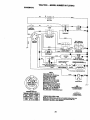
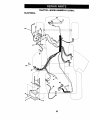
• Check widng. See electrical wiring
adjustment is necessary, proceed as
diagram in the Repair Parts section.
follows:
• With engine not running, move choke
control (located on dash panel) to full
choke position.
25
• Remove air cleaner cover, filter and
cadddge plate to expose carburetor
choke (see "AIR FILTER" in the
Maintenance section of this manual).
• Choke should be closed. If it is not,
loosen casing clamp screw and move
choke cable until choke is completely
closed. Tighten casing clamp screw
securely.
• Reassemble air cleaner.
Clamp Screw_
Quarter Circle
Swivel
FINAL SETTING
-
• Start engine and allow to warm for five
minutes.
Make final adjustments with
engine running and shift/motion
control
lever in neutral (N) position.
• With throttle control lever in slow
position, hold throttle lever against idle
speed screw and adjust idle speed
screw to obtain 1200 to 1400 RPM.
• While still holding throttle lever against
idle speed screw, turn idle mixture
screw in (clockwise) until engine begins
to die and then tum out (counterclockwise) until engine runs rough. Turn
screw to a point midway between those
two positions.
• Continue to hold throttle lever against
idle speed screw and adjust idle speed
screw to obtain 900 to 1200 RPM.
Release throttle lever.
ACCELERATION
TEST -
• Move throttle control lever from slow to
clamp.I
"'--
Choke Lever
Screw_
TO ADJUST
CARBURETOR
The carburetor has been preset at the
factory and adjustment should not be
necessary. However, minor adjustment
may be required to compensate for
differences in fuel, temperature, altitude or
load. If the carburetor does need adjustment, proceed as follows:
In general, tuming the mixture screw In
(clockwise) decreases the supply of fuel
to the engine giving a leaner fuel/air
mixture. Turning the mixture screw out
(counterclockwise)
increases the supply
of fuel to the engine giving a richer fuel/air
mixture.
IMPORTANT:
Damage to the needles and
the seats in carburetor
may result it screw
is tumed in too tight.
PRELIMINARY
SETTING
fast position.
If engine hesitates or dies,
turn idle mixture screw out (counterclockwise)
1/8 tum. Repeat test and
continue to adjust, if necessary, until
engine accelerates smoothly.
High speed stop is factory adiusted. Do
not adjust - damage may result.
IMPORTANT:. Never tamper with the
engine governor, which is factory set for
proper engine speed. Overspesding the
engine above the factory high speed
setting can be dangerous. If you think the
engine-govemed
high speed needs
adjusting, contact your nearest authorized
service center/department,
which has
proper equipment and experience to
make any necessary adjustments.
ldle Speed
crew
Idle Mixture
Screw
hrottle Lever
Idle Speed
• Be sure you have a clean air filter, and
the throttle control cable and choke are
Screw
adjusted properly (see above).
• With engine off tum idle mixture screw
In (clockwise) closing it finger tight and
then turn out (counterclockwise) 1-1/4
to 1-112 turns.
Throttle
Lever
26
Mixture
Immediately prepare your tractor for
storage at the end of the season or if the
tractor will not be used for 30 days or
more.
_CAUTION:
Never store the tractor with
gasoline in the tank inside a building
where fumes may reach an open flame or
spark. Allow the engine to cool before
storing in any enclosure.
TRACTOR
Remove mower from tractor for winter
storage. This will allow you to clean it
thoroughly. Remove all dirt, grease,
leaves, etc. Store in a clean, dry area.
• Clean entire tractor (See "CLEANING"
in the Maintenance section of this
manual).
• Inspect and replace belts, if necessary
(See belt replacement instructions in
the Service and Adjustments section of
this manual).
• Lubricate as shown in the Maintenance
section of this manual.
• Be sure that all nuts, bolts and screws
are securely fastened. Inspect moving
parts for damage, breakage and wear.
Replace if necessary.
• Touch up all rusted or chipped paint
surfaces; sand lightly before painting.
BATTERY
• Fully charge the battery for storage.
• After a period of time in storage, battery
may require recharging.
• To help prevent corrosion and power
leakage during long periods of storage,
battery cables should be disconnected
and battery cleaned thoroughly (see
"TO CLEAN BATTERY AND TERMINALS" in the Maintenance section of
Also, experience
indicates that alcohol
blended fuels (called gasohol or using
ethanol or methanol) can attract moisture
which leads to separation and formation of
acids during storage. Acidic gas can
damage the fuel system of an engine
while in storage.
• Drain the fuel tank.
• Start the engine and let it run until the
fuel lines and carburetor are empty.
• Never use engine or carburetor cleaner
products in the fuel tank or permanent
damage may occur.
• Use fresh fuel next season.
NOTE: Fuel stabilizer is an acceptable
alternative in minimizing the formation of
fuel gum deposits during storage. Add
stabilizer to gasoline in fuel tank or
storage container. Always follow the mix
ratio found on stabilizer container. Run
engine at least 10 minutes after adding
stabilizer to allow the stabilizer to reach
the carburetor. Do not drain the gas tank
and carburetor if using fuel stabilizer.
ENGINEOIL
Drain oil (with engine warm) and replace
with clean engine oil. (See "ENGINE" in
the Maintenance section of this manual).
CYLINDER(S)
• Remove spark plug(s).
• Pour one ounce of oil through spark
plug hole(s) into cylinder(s),
•Tum ignition key to =START" position for
a few seconds to distribute oil.
• Replace with new spark plug(s).
OTHER
• Do not store gasoline from one season
to another.
this manual).
• After cleaning, leave cables disconnected and place cables where they cannot
come in contact with battery terminals.
• If battery is removed from tractor for
storage, do not store battery directly on
concrete or damp surfaces.
• Replace your gasoline can if it starts to
rust..Rust and/or dirt in your gasoline
will cause problems.
• If possible, store your tractor indoors
and cover it to give protection from dust
and dirt.
• Cover your tractor with a suitable
protective cover that does not retain
moisture. Do not use plastic. Plastic
cannot breathe, which allows condensation to form and cause your tractor to
rust.
IMPORTANT:
Never cover tractor while
engine and exhaust areas are still warm.
ENGINE
FUEL SYSTEM
IMPORTANT:
It is important to prevent
gum deposits from forming in essential
fuel system parts such as carburetor, fuel
filter, fuel hose, or tank during storage.
27
TROUBLESHOOTING CHART
PROBLEM
CAUSE
Will not start
• Out of fuel.
• Engine not"CHOKED"
properly.
• Engine flooded.
• Fill fuel tank.
• See =TO START ENGINE" in
•
•
•
•
•
•
•
•
CORRECTION
• Engine valves out of adjustment.
attempting to start.
Replace spark plug.
Clean/raplace air filter.
Replace fuel filter.
Drain fuel tank and carburetor, refill tank with fresh
gasoline and replace fuel filter.
• Check all wiring.
• See =To Adjust Carburetor"
in Service and Adjustments
section.
• Contact an authorized service center.
•
•
•
•
•
•
•
•
•
•
Bad spark plug.
Dirty air filter.
Dirty fuel filter.
Water in fuel.
• Loose or damaged wiring.
• Carburetor out of adjustment.
Hard to start
Dirty air filter.
Bad spark plug.
Weak or dead battery.
Dirty fuel filter,
Stale or dirty fuel.
• Loose or damaged wiring.
• Carburetor out of adjustment.
• Engine valves out of adjustment.
Engine will not tum
over
• Clutch/brake pedal not
depressed.
• Attachment clutch is en:
gaged,
• Weak or dead battery.
• Blown fuse.
• Corroded battery terminals.
• Loose or damaged wiring.
• Faulty ignition switch.
• Faulty solenoid or starter.
• Faulty operator presence
switch(es).
Engine clicks but
will not start
Operation section.
• Wait several minutes before
• Weak or dead battery.
• Corroded battery terminals.
28
Clean/replace air filter,
Replace spark p!ug.
Recharge or replace battery.
Replace fuel filter.
Drain fuel tank and refill with
fresh gasoline.
• Check all wiring.
• See =ToAdjust Carburetor"
in Service and Adjustments
section.
• Contact an authorized service center.
• Depress clutch/brake pedal,
• Disengage
clutch.
attachment
• Recharge or replace battery.
• Replace fuse.
• Clean battery terminals.
• Check all widng.
Check/replece
ignition
switch.
• Check/replace
solenoid or
starter.
• Contact an authorized seP
vice center.
o- Recharge or replace battery.
• Clean battery terminals.
TROUBLESHOOTING
CHART
PROBLEM
CAUSE
CORRECTION
Engine clicks but
will not start
(cont'd)
• Loose or damaged wiring.
• Faulty solenoid or starter.
• Check all wiring.
• Check/replace solenoid or
starter.
Loss of power
• Cutting too much grass/
too fast.
• Throttle in =CHOKE" position.
• Build-up of grass, leaves
and trash under mower.
• Dirty air filter.
• Low oil level/dirty oil.
• Faulty spark plug.
• Set in "Higher Cut" position/
reduce speed.
• Adjust throttle control.
• Dirty fuel filter.
I • Stale or dirty fuel.
housing.
• Clean/replace air filter.
• Check oil level/change oil.
• Clean and regap or change
spark plug.
• Replace fuel filter.
• Drain fuel tank and refill with
I • Water in fuel.
fresh gasoline.
• Drain fuel tank and carbure-
• Spark plug wire loose.
• Dirty engine air screen/
fins.
• Dirty/clogged muffler.
• Loose or damaged wiring.
• Carburetor out of adjustment.
• Engine valves out of adjustment.
Excessive vibration
• Clean underside of mower
• Wom, bent or loose
blade.
• Bent blade mandrel.
• Loose/damaged part(s).
tor, refill tank with fresh gasoline and replace fuel filter.
• Connect and tighten spark
plug wire.
• Clean engine air screen/fins.
• Clean/replace
muffler.
• Check all wiring.
• See =To Adjust Carburetor"
in Service and Adjustments
section.
• Contact an authodzed service center.
• Replace blade.Tighten
blade bolt.
• Replace blade mandrel.
• Tighten loose part(s). Replace damaged parts.
I • Faulty operator-safety
Engine continues
to run when operapresence control system.
tor leaves seat with
attachment clutch
engaged
• Check widng, switches and
connections. If not
corrected, contact an authorized service center.
Poor cut - uneven
• Replace blade, l_ghten
blade bolt.
• Level mower deck.
• Clean underside of mower
•Wom, bent or loose
blade.
• Mower deck not level.
• Buildup of grass, leaves,
and trash under mower.
• Bent blade mandrel.
29
housing.
• Replace blade mandrel.
TROUBLESHOOTING
PROBLEM
CHART
CAUSE
CORRECTION
Poor cut - uneven
(cont'd)
• Clogged mower deck vent
holes from buildup of
grass, leaves, and trash
around mandrels.
• Clean around mandrels to
open vent holes.
Mower blades will
not rotate
• Obstruction in clutch
mechanism.
• Remove obstruction.
Worn/damaged
drive belt.
Poor grass discharge
mower
• Replace
mower drive belt.
Frozen idler pulley.
Frozen blade mandrel.
• Replace
• Replace
idler pulley.
blade mandrel.
• Engine speed too slow.
Travel speed too fast.
Wet grass.
Mower deck not level.
Low/uneven tire air pressure.
Worn, bent or loose
blade.
Buildup of grass, leaves
and trash under mower.
Mower drive belt worn.
Blades improperly
stalled.
in-
Improper blades used.
Clogged mower deck vent
holes from buildup of
grass, leaves, and trash
around mandrels.
Headlight(s) not
working (if so
equipped)
• Switch is =OFF".
• Bulb(s) burned out.
• Faulty light switch.
Loose or damaged wiring,
Blown fuse.
Battery will not
charge
Engine "backfires"
when turning engine "OFF"
• Place throttle control in
"FAST" position.
• Shift to slower speed.
• Allow grass to dry before
mowing.
• Level mower deck.
• Check tires for proper air
pressure.
• Replace/sharpen
blade.
Tighten blade bolt.
• Clean underside of mower
housing.
• Replace mower drive belt.
• Reinstall blades sharp edge
down.
• Replace with blades listed in
this manual.
• Clean around mandrels to
open vent holes.
• Turn switch "ON'.
• Replace bulb(s).
• Check/replace
light switch.
• Check wiring and connections.
• Replace fuse.
Bad battery cell(s).
• Poor cable connections.
Faulty regulator (if so
equipped).
Faulty alternator.
Engine throttle control not
set at "SLOW"
position for 30 seconds
before stopping engine.
30
• Replace battery.
• Check/clean all connections.
• Replace regulator.
• Replace
alternator.
• Move throttle control to
"SLOW" position and allow
to idle for 30 seconds before
stopping
engine.
TRACTOR - - MODEL NUMBER 917_70912
SCHEMATIC
-
llllll
BA'FrERY
AMMETER
(OPTIONAL)
:_-,
,=@ : ,C_---
......
.._
,
SOLENOID
(PEDAL UP)
IGNITION
(NOT OCCUPIED)
SWITCH
WNITE t........
au_
I
I
GROUNDING
CONNECTOR
(CLUTCH OFF)
CHARGI4G SYSTEMOUTPUT
3AMP
DC @ 3_0
RED
uc_rr_ _t_
SEAT SWITCH
m V_.T8 AC MIIN.@ _
P_M
R_
D
I_
t
L
NoTE
I
YOUR TRACTOR IS
EQUIPPED WiTH A SPECIAL
ALTERNATOR SYSTEM.
THE LIGHTS ARE NOT
CONNECTED TO THE
BATTERY, BUT HAVE THEIR
OWN ELECTRICAL SOURCE.
BECAUSE OF THIS, THE
BRIGHTNESS OF THE LIGHTS
WILL CHANGE WITH ENGINE
SPEED. AT IDLE THE LIGHTS
WILL DIM. AS THE ENGINE IS
SPEEDED UP, THE LIGHTS
WILL BECOME THEIR BRIGHTEST.
I
EROWN
_Ip-'_°
_
I
_
I
fF'_
_
HEADUGHTS
i
lW"
NON-REMOVABLE
CONNECTIONS
O
IGNITION SWITCH
REMOVABLE
CONNECTIONS
W|RING INSUI..ATED CLIPS
NOTE: IF WIRING INSULATED CLIPS WERE REMOVED FOR
SERVICING OF UNIT, THEY SHOULD BE REPLACED TO
PROPERLY SECURE YOUR WIRING,
31
I
TRACTOR - MODEL NUMBER 917.270912
ELECTRICAL
22
I
41
I
I
J
I !
i
i
J!
i
/
L
25
//
I
I
/
/
32
TRACTOR- MODEL NUMBER 917.270912
ELECTRICAL
KEY PART
NO. NO.
1
2
8
10
11
12
16
19
21
22
24
25
26
27
28
29
30
33
40
41
42
43
45
52
55
163465
74760412
7603J
145211
150109
145769
153664
Std551125
166182
4152J
4799J
146148
16618O
73510400
145491
121305X
163968
140403
170217
71110408
131563
145673
t21433X
141940
17490508
DESCRFIION
Battery 12 VOLT 28 AMP
Bolt Hex Hd 1/4.20unc x 3/4
Case Battery
Bolt, Btr Front 1/4-20 x 7-1/2
Holddown Battery Front Mount
Nut, Push Nylon Battery Front 1/4
Switch, interlock Push-in
WasherLock 1/4
Harness Light Socket (W/4152j)
Bulb Light #1156
Cable Battery
Cable Battenj
Fuse
Nut Keps Hex 114-20 Uric
Cable Ground
Switch Seat
Switch Ign
Key Molded Craftsman
Harness Ign
BoltBIk. FinHex 1/4-20Uncxli2
CoverTerminal
Solenoid
Ammeter Rectangular6 Amp
Protection Wire Loop
Screw Thdrot 5/16-18 x 1/2
NOTE: Allcomponentdimensions
givenin U. S.
inchesI inch= 25/4 mm
33
TRACTOR - MODEL NUMBER 917.270912
CHASSIS AND ENCLOSURES
28
12
208
2O8
11
74
34
TRACTOR - MODEL NUMBER 917.270912
CHASSIS AND ENCLOSURES
I_'Y PAFIT
NO. NO.
DESCRIPT'K_
1 169630
2 16O061
3 17060612
5 155272
9 168337X013
10 S'11Ta33710
11 155927
12 145660
13 169117X010
17 144983X558
18 126938')(
20 156437
23 124028X
25 19131312
26 $10541437
28 16O271X,558
29 155217X599
30 164918X558
31 139976
37 17490508
38 169_34
51 73800400
52 19091416
53 145201
54 161464
55 145202
57 S'[0522507
58 140547
6O STD533707
64 154798
74 STD541437
114 158112
115 17060620
116 19131614
142 165867
143 154966
144 154207
145 156524
159 155123X428
206 170165
207 17670506
208 176706O8
- - 5479J
Chassla Assembly
Dmvtser
Screw 3/8-16 x 3/4
BumperHoodiDash
Dash
Bolt, Carriage 3/8-16 x 1
Panel, Dash, L.H.
Clip Tinnerman Gdfle P/L
Panel, Dash, R.H.
HoodAssembly
BumperHood
Plate Mtg Battery Fuel Tank
Bushing,Snap, Nylon, Fuel Line
Washer 13/32 x 13/16 x 12 Gauge
Locknut, Hex, with Insert 3/8-16 Uric
GflUew/C|_s MS-558
Lens, Grille
FendiFtrest
Bracket, Fender Support
Screw Thdrot 5/16-18 x 1/2
Pivot Bracket Assembly, L,H.
Nut Lock w/Insert 1/4-20 UNC
Washer 9/32 x 7/8 x 16 Ga.
Bracket Qdlle Plckoff LH
ScrewHexWshd
8-18 x7/8
Bracket Gdlle Pickoff RH
Bolt, Fin Hex 1/4-20 UNC x .75
Air Duct P/L B&S
Bolt Rdhd Sqnk 3/8-16 UNC x 3/4
OashLower STLT
NutCrownlock 3/8-16 UNC
Keeper Belt Rear Lh Sit
Screw 3/8-16 x 1-1/4
Washer 13/32 x 1 x 14 Ga.
Plate ReinforcementSTLT
Bracket Swaybar Chassis
Bracket Pnt Footrest STLT
Rod Pivot ChessisA-Iood
Cupholder
Bolt Shoulder 5/16-18 "I-I"
Screw Tlldrol 5/16-18 x 1/2
Screw Thdrol 3/8-16 x 1/2
Plug Button
NOTE: All component dimensionsgiven in U. S.
inches 1 inch = 25/4 mm
35
TRACTOR - MODEL NUMBER 917.270912
GROUND DRIVE
il
Ji
72
$66
6
52
26
27
116
TRACTOR - MODEL NUMBER 917#.70912
GROUND DRIVE
KEY PART
NO. NO.
1
2
3
4
5
6
8
10
11
13
14
18
19
21
22
24
25
26
27
28
29
30
31
32
34
35
36
37
38
39
40
41
42
47
48
49
50
51
52
53
55
56
57
58
59
61
........
146682
123666X
12(XX_28
121520X
17060512
165866
ST1_61210
105701X
74550412
10040400
STD523719
$TD541437
106933X
130804
STD541237
106888X
STD5510_7
STD561210
145204
71673
169592
127275X
$10523107
155071
120183X
STD551062
STD571810
131494
STD523727
4470J
165838
19131312
127783
154407
123205X
STD523"/15
STD541437
_1431
105710X
105709X
STD523712
130601
127274X
169691
17060612
_
Trensaxle (See Breakdown)
Peedess 206-545C
Spdng, Retum, Breke
Pulley, Transaxla
Ring, Ftetainer
Strap, Torque
Screw 5/16-18 x 3/4
RodShifterFenderSTLT
Pin, CoRer
Washer, Shift Plate
Bolt 1/4-28UNFW/PatohGr.B
WasharLockHvyHelical
BoltFInHex3J8-16UNCxlGr5
Nut
Knob
Rod, Brake
Nut
Spdng, Brake Rod
Washer
Pin
Rod, PaddngBrake
Cap, ParklngBrake
Bracket, Trensaxle
Keeper, BeE, LH.
Bolt
Shaft Assembly, Foot Pedal
Beedng, Nylon
Washer
RoUPin
Pulley, Idler, Flat
Bolt
Spacer, Split 395 x .59
Keeper, Belt, Idler
Washer 13/32 x 13/16 x 12 Ge.
Pulley, Idler, V-Groove, Plastic
Bellcrenk Clutch Grnd Dw St[
Retainer, Belt
Bolt
NutCrownLoc,k3/8-16UNC
NutCrownLcoks/16-18UNC
Unk, Clutch
Spdeg, C|utchRetum
BoftFInHex 3/8-16x1-1/4
V-Belt, GroundDdve
Keeper, Belt, R.H.
Keeper, Belt, Center Span
Screw 3/6.16x3/4
I<]EYPART
NO. NO.
DESCRB3TION
62 8883R
63 140186
64 71170764
65 STD551143
66 154778
70 134683
72 19132012
74 137057
75 121749)(
76 STD581075
77 123583X
78 121748X
79 S_5
80 145090
81 165592
82 165711
83 19171216
84 166231
85 150360
89 158391X428
90 124346X
96 STD624003
112 19091210
113 127285X
116 72110610
145 74490540
150 165850
151 19133210
156 166002
158 165589
159 165494
161 72140406
162 73680400
163 74780416
164 19091010
165 165623
166 166880
168 16549_
169 165580
170 165849
197 16,9613
198 16959_
20272110612
204 17060516
Cover, Pedal
Pulley, Engine
Belt, Hex 7/16.20 x 4 Grade 5
Washer
Keeper, Belt, Engine, Foo_-Proof
Guide, Mower Drive Belt, R.H.
Washer 13/32 x 1-1/4 x 12 Ga.
Spacer, Axle
Washer 25/32 x 1-1/4 x 16 Ga.
E-Ring
Key, Square 2.0x .1845/.1865
Washer 25/32 x 1-5/8 x 16 Ga
Key WoodnJfl
Arm, Shift
Shaft Asm CrossTapered 650 20
Spdng,Torsion
Washer 17132 x 3/4 x 16 Ga.
LinkTrensaxls
Nut, Nylock
Console, Shift, STLT
Nut, Self-Thding,Wsh Hd 1/4
Retainer Spdng 1"
Washer 9/32 x 3/4 x 10 Gauge
Strap Torque 90 Degrees
Bolt Rdhd Sqneck 3/8-16 x 1.25
Bolt, Hex Flghd 5/16-18 Gr. 5
Bushing Be,crank Grd. Drive
Washer 13/32 x2 x 10 Ga.
Washer Srrted 5/161D x 1.125
Bracket Shift Mount
Hub Tapered Flange Shift Lt
Bolt Rdhd Sqnk 1/4-20 x 3/4 Gr.5
Nut Crownlock 1/4-20 Unc
BoR Hex Fin 1/4-20Unc x I Gr5
Washer 5/8 x .281 x 10 Ga
Bracket Pivot Lever
Screw 3/16-18 x 5/8
Boft Shoulder 5/16-18 x .561
Plate Fastening Lt
Keeper Belt Transax_eGear
NyltnerSnap-In
WasherNytiner
Bolt Carr. SH 3/8-16 x 1-1/2 Gr. 5
Screw 5/16.18 x I SMGML
NOTE: All component dimensions given in U. S.
inches 1 inch = 25/4 mm
37
TRACTOR - MODEL NUMBER 917.270912
STEERING
q.-.
"
•
I
I
/17
47
2I
43
I
I
f
38
TRACTOR - MODEL NUMBER 917.270912
STEERING
I_*Y PART
NO. NO.
DES_
1
2
3
4
5
6
7
8
9
10
11
13
15
17
18
19
22
23
25
26
27
28
29
30
32
36
37
38
39
40
41
42
43
44
46
47
51
54
62
63
65
66
67
68
79
80
82
85
Steedng Wheel
Axle Assembly STMP Dropped STL
Spindle Assembly, LH.
Spindle Assembly, R.H.
Beadng, Race, Thrust, Hardened
Washer 25/32 x 1-5/8 x 16 Gauge
Washer 27/32 x 1-1/4 x 16 Gauge
Ring, Klip
Beadng.SteedngColumn
Draglink
Washer, Lock
Spacer, Beadng, Axle
Nut, Hexflanga Lock
Shaft Assembty, Steering
Washer, Thrust .515 x .750 x .033
Support, Shaft
Screw Hex Wshnd Torx
Pittman Shaft Assembly
Bracket, Steedng
Bushing,Unk, Drag
Gear, Sector
Washer 13/32 x 7/8 x 16 Gauge
Screw 3/8-15 x 3/4
Pin
Rod, Tie
Bushing, Steedng
Screw
Insert, Steering Wheel
Washer 13/32 x 2-3/8 x 12 Gauge
Gripco Nut
Adaptor, Steering Wheel
Boot, Steering Shaft
Washer 25/32 x 1-1/4 x 16 Gauge
Extension Shaft Steering LR.LT
Cap, Spindle
Fitting, Grease
Nut Lock Hex w/Ins. 5/16-18 UNC
BoltFin Hex 5/16-18 UNC x 1-1/4
Kit Steering Asm Service
Bolt, Fin Hex 3/8-16 UNC x 1 Gr 5
Spacer Axle
Bearing Arm Pittman
Bolt RDHD SQNK 3/6-16 x 2-1/4
Axle, Brace
Washer 13/32 x 1-1/4 x 12 Ga
Bolt Hex Nylqn 3/8-16 x 3/4
Bracket Susp Chassis Front
FastnerChdstmas Tree
139768
154427
169840
169839
6266H
121748X
19272016
12000029
3366R
159832
_1137
136518
145212
156546
57079
160395
165857
165851
154406
126847X
136874
19131416
17060612
STD561210
13O465
155O99
152927
139769
19133812
STD541537
100711L
145054X428
121749X
153720
121232X
6855M
$10541431
7478O520
167902
STD523710
160367
1544O4
72110618
169827
19132012
74950612
169835
133835
NOTE: All component dimensions given in U. S.
inches 1 inch = 25/4 mm
39
TRACTOR - MODEL NU MBER 917.270912
ENGINE
39
29
\
OPTIONAL
EQUIPMENT
Spark Arrester
40
TRACTOR - MODEL NUMBER 917.270912
ENGINE
IQEYPART
NO. NO.
1
2
162152
17720410
3
......
4
5
6
7
8
10
11
12
13
14
15
16
17
23
25
26
27
29
31
32
33
34
37
149723
144069
144O68
138129
150176
145552
$11To51125
STD522507
165287
13280336
1320O3O0
STD551237
17490624
169837
145996
73920600
152927
137180
157103
161696
123487X
106082X
854,3R
38
.......
39
45
81
109227X
17060612
128861
DESCRIPTION
Control, Throt Peddle 32 22
Screw, Hex Thd Cut 1/4-20 x 5/8
Engine, B&S, (See Breakdown) No. 461707-0145.E3
Muffler Exhaust
Exhaust Asm. Left
Exhaust Asm. R',ght
ClampTube Double Engine
Bott 5/16-18unc x 3/4 W/Seres
Heat Shield LI
Washer Lock HW. Helk_al 1/4
BoltFin Hex 1/4-20Unc x .75
Gasket, Muter
Nipple, Pipe 4-1/2
Etbow,Star,,derd90_, 3/8-18 HPT
Washer Lock Ext Tooth 3_
Screw Thdrot 3/8-16x1-1/2 Ty_t
Shield, Bm/Dbr Guard
ControlChoke
Nut Keps 3/8-24 Unf
Screw TI" #10-32 x 5 x 3/8 Flange
Arrestor, Spark
Tank, Fuel
Cap Fuel Guage
Clamp,Hose
Spacer Pad
Line, Fuet
Plug,Oil Drain (See Engine Breakdown)
Pad Idler
Screw 3/8-16 x 3/4 SMGML
Nut Range 1/4-20 Starter Nut
NOTE: Allcomponent dimensionsgiven in U. S.
inches 1 Inch = 25/4 mm
41
TRACTOR - MODEL NUMBER 917.270912
SEAT ASSEMBLY
KEY PART
NO. NO,
1 140123
2 140551
3 71110616
4 19131610
5 145006
6 STD541437
7 124181X
8 17000616
9 19131614
10 155925
11 166369
12 121246X
DESCRIPTION
Seat 3350 BIkJblkCraftsman
Bracket Pnt Pivot Seat (blk)
Bolt Fin Hex 3/8-16unc X 1
Washer 13/32 X 3/4 X 10 Ga
Clip Push In Hinged
Nut Hex Lock w/Ins 3/8-16 Unc
Spdng Seat Cpmn 2 250 BIk ZI
Screw 3/8-18 x 1.5 SMGML
Washer 13/32 X 1 X 14 Ga
Pan Pnt Seat (blk)
Knob Seat
Bracket Pnt Mounting Switch
_
PART
NO. NO.
DESCRIPTION
13
14
16
16
17
21
22
24
25
Bushing Snap B|k Ny150 Id
Bolt Rdhd Sht Nk 1/4-20x1-1/2
Spacer Split 28 X 96 Zinc
Spring Cprsn 1 27 BIk Pnt
Nut Lock 1/4 Lgo F!g Gr 5 Zinc
Bolt Shoulder5/1 6-18 Unc-2A
Nut Hex Lock w/Ins 5/16-18
Washer 17/32 X 1-3/16 X 12 Ga.
Bolt Shou_k_r5/16-18 X 62
121248X
7205041.2
134300
121250X
123976X
171852
STD541431
19171912
127018)(
NOTE: All component dimensions given in U. S.
inches 1 Inch = 25/4 mm
42
TRACTOR - MODEL NUMBER 917.270912
DECALS
7
7
13
2
15
KEY PART
NO. NO.
I 156439
2 165392
3 171696
4 171697
5 163207
6 133644
7 163259
6 171808
9 163204
11 156368
OESCRIPTK)N
Decal, Fender Danger Seam
Decal, Engine
Decal, Hood, R.H.
Decal, Hood, LH.
Decal, Fender
Decal, Maintenance
Decal, Panel Dash B&S
Decal, Rplcmnt
Decal, Fender, Craftsman Gold
Decal, Fender STLT Oper Inst E,/S
WHEELS AND TIRES
7,°
I<_t
NO.
13
15
19
20
22
--- ---
PART
NO,
146046
160396
138047
166887
149516
138311
165800X428
165799X428
173529
173530
I_EY PART
NO. NO.
1 59192
2 65139
3 106222X
4 59904
DESCRIPTION
Decal, V-Belt Dr Sch Tractor
Decal, Mower Drive Schematic
Decal, Battery Diehard Sears
Decal, Deck Mower EZ3
Decal, Battery
Decal, LiftHandle
Pad Footrest LH STLT
Pad Footrest RH STLT
Owners Manual, English
Owner's Manual Spanish
DESCRIPllON
Valve Cap, Tire
Stem, Valve
Tire, Front
Tube, FrontTim
(Not Provided, Service Item
o_y)
5
6
106732X42"/
2781-1
Rim, Front
Fitting,Grease (Front Wheel
7
90401-1
Beadng, Flange (Front Wheel
106108X427
122082X
7152J
Rim, Rear
Tire, Rear
Tube, RearTire
(Not Provided, Service Item
one,)
8
9
10
orw)
11 104757X
Cap, Axle
- - 144334
Sealant, Tire 10oz.
NOTE: Allcomponent dimensionsgiven In U. S.
Inchea I inch = 25/4 mm
TRACTOR - MODEL NUM BER 917.270912
LIFT ASSEMBLY
t 8
!
i'
i
I'
I
5
I'
.I
j
13
2
6
6
4
13
19
2O
13
15
13 ----_
32
31 _
19
32
d.A
2O
TRACTOR-
MODEL NUMBER 917.270912
LIFT ASSEMBLY
I_'Y PART
NO. NO.
D_CRIPll(_
1
2
3
4
5
6
7
8
11
12
13
15
16
17
18
19
20
31
32
Lift Lever Inner Wire Assem_y
Shaft Assembly, Lift
Pin, Groove
E-Ring
Washer 21/32 x 1 x 21 Gauge
Beadng, Nylon
Grip, Handle, Fluted
Button, Plunger, Red
Unk, Lift, LH.
Unk, Lift, R.H.
Retainer Spdng
Unk, Front
Nut, Hex, Jam 1/2-13UNC
Trumio_
NutLock w/Wsh 1/2-13UNC
Arm, Suspension, Rear
Retainer Sprlng
Beating, Pvt, Lift Specla_
Nut, Crownlock 3/8-24
159460
159471
105767X
12000002
19211621
120183X
125631X
122365X
139865
139866
STD624_06
167253
73350800
130171
73800800
139868
163552
140302
73540600
NOTE: Artcomponent dimensionsgiven in U. S.
inches 1 inch = 25/4 mm
45
TRACTOR - MODEL NUMBER 917.270912
MOWER DECK
68
34
21
22
/23
24
\
2
26
16
1
27
TRACTOR - MODEL NU MBER 917.270912
MOWER DECK
PART
NO. NO.
1
2
3
165892
STD533107
138017
4 165460
5 STD624008
6 130832
8 850857
9 S'10551137
10 140296
11 134149
12 129695
13 137645
14
15
16
18
19
20
21
22
23
24
25
26
27
28
29
30
31
32
33
34
35
36
37
128774
110485X
140329
72140505
132827
159770
STD541431
134753
131267
105304X
123713X
110452X
130968X428
19111016
131491
157722
129963
153535
137266
STD533717
133835
131494
STD551037
40
44
45
46
48
49
50
51
52
53
54
55
STD541437
140088
STD624003
137729
133944
155066
131340
STD541410
139888
131845
133943
155046
_
PAre"
NO. NO.
DESCRIPYllON
MowerDeckAssembly,42"
Bolt
Bracket Assembly,Sway Bar,
Front
Bracket Sway Bar 38/42" Deck
RetalaerSpdng
Arm, Suspension, Rear
Bolt, Hex 3/8-24 x 1.25 Gr. 8
Washer, Lock
Washer, Hardened
Blade,Mulching
Baadng, Ball
Shaft Assembly, Mandrel, Vented
(includes Key
Number12)
Housing,Mandrel, Vented
Bearing, Bali, Mandrel
Stdpper, Vented Mower Deck
Bolt, Cardage 5/16-18x5/8
Bolt, Shoulder
Baffle, Vortex
NutCrownlock5/16-18UNC
Stiffener Bracket
Bracket, Deflector
Cap, Sleeve
Spdng, Torsion, Deflector
Nut, Push
Shield, Deflector
Washer 11/32x5/8x16Ga.
Rod, Hinge
ScrewThdrolWasherHead
Washer, Spacer
Pulley, Mandrel
Nut, Toplock, Flanged
Bolt
Fastner, ChristmasTree
Pulley, Idler, Flat
Washer 13/32 x13/16 x16
Gauge
NutCrownlock3/8-16UNC
Guard, MandreI, L.H.
Retainer
Screw, Thd. Roll 1/4-20 x 5/8
Washer, Hardened
RollerAssembly, CamFollower
Bolt, Shoulder #10-24 Grade 5
Locknut
Bolt, Shoulder 5/16-18UNC
Arm Assembly, Pad, Brake
Washer, Hardened
Arm, Idler
56 165723
59 141043
67 14_46
68 144959
9_ STD541437
101 136420
102 71161010
103 19061216
104 STD551110
105 160793
106 2029J
111 155197
112 155198
113 17060512
114 STD541431
115 72110504
116 48961-1
117 165746
11873930600
119 STD551G37
121 143723
128 1533..o0
129 19131312
130 STD523710
DESCRIPTION
Spacer, Retainer
Guard, TUV Idler
KnobCustom Oval
V-Belt
Nut
MulcherCover
Screw
Washer #10
Washer, Lock
Latch Assembly, Bagger
Nut, Weld
Bracket, Gauge, Wheel L.H.
Bracket, Gauge, Wheel R.H.
Screw 5/16-18 x 3/4
Nut, Hex, Keps 5/16-18 UNC
Bolt, Carriage 5/16 UNC x 1/2
Bolt, Shoulder
Wheel, Gauge
Nut, Centerlock 3/8-16
Washer 3/8 x 718x 14 Gauge
Bracket
Washer Felt
Washer 13/32 x 13/16 x 12 Ga.
Bolt, Fin Hex 3/8-16 UNC x 1
Gr. 5
131 STD533710
Bolt, Rdhd Sqnk 3/8-16UNC x 1
142 165890
Arm Spdng BrakeMower
143 157109
Bracket Arm Idler 42"
144 158634
Keeper Belt 42" Clutch Cable
145 165888
Pulley Idler Flat
146 165891
Bolt Carriage Idler
147 131335
Spdng Extension
148 169022
Spdng Return Idler
149 165898
Retainer Spdng YellowZinc
150 19091216
Washer 9/32 x 3/4 x 16 Ga.
151 169670
Bracket Clutch
152 169676
Cable Clutch 42 In
153169674
Washer Flat 3/8" Type B
154 169675
Spdng Retainer
155 169671
SpringRetention Lever
156 169672
Spacer
157 169669
RodClutch
158 17720410
Screw Hex Thd Cut 1/4-20 x 5/8
159 STD533717
Bolt Rdnd Sqn 3/8-16Unc x 1-3/4
.o 130794
Mandrel Assembly (includes Key
Numbers 8-10, 12-15, 31 and 32)
- - 169583
Mower Deck,Complete (Standard
Deck, Order Separately Mulchar
Plate and Gauge Wheel
Components, Key Nos. 101-106
and111-121)
NOTE: All component dimensionsgiven in U. S.
inches I inch = 25/4 mm
47
TRACTOR - MODEL NUMBER 917.270912
PEERLESS TRANSAXLE-MODEL NUMBER 206-545C
I
I
11
48
TRACTOR - MODEL NUMBER 917.270912
PEERLESS TRANSAXLE-MODEL
KEY PART
NO. NO.
1
2
3
4
5
6
6A
7
8
8A
9
10
11
12
13
772147
780086A
770128
776395
776409
778364
778369
778330
792180
792047
784352
784378
778334
778309
778368
14
778368
15
17
18
20
21
22
25
25A
26
27
28
29
778370
786188
786102
792077A
792078
792079
792073A
792177
792125
792035
788040
780072
29A 780160
29B 780051
29C 780199
30
780108
31
780001
31A 780195
32
34
35
35A
36
37
38
788083
780194
780193
780197
790075
790007
799021
NUMBER 206-545C
KEY PART
NO. NO.
DESCRIPTION
Transaxte Cover
Needle Beadng 5/8"
Transaxle Case
Countershaft
Output Shaft
Spur Gear (38 teeth)
Spur Gear (15 teeth)
Spur Gear (11 teeth)
Shift Key
Woodruff Key #9
Shift Collar
Shift Rod & Fork
Bevel Gear (30 teeth)
Input Bevel Pinion (13 teeth)
Bevel Gear (13 teeth)
(Include. 14)
Bevel Pinion (13 teeth)
(Include. 13)
Ring Gear (43 teeth)
Drive Pin
Spacer 1.130 X .695
Bell 5/16" die
Set Screw 3/8 - 16 x 3/8"
Spring .310 OD x .625 L
Screw 1/4 - 20 x 1-1/4"
Screw 1/4-20 x 1-3/8"
Retaining Ring (pkg of 2)
Retaining Ring
Retaining Ring
Thrust Washer
.627 ID x .031W
Thrust Washer
.762 ID x .031W
Thrust Washer
.762 ID x .031W
Anti-Rotation Washer .632
Cup Washer
1.127 ID x .032W
Flat Washer
.750 ID x .056W
(Use As Needed)
Fiat Washer
,750 ID x .062W
Oil Seal 5/8"
Bushing ,563
Ranged Bushing 5 / 8" ID
Ranged Bushing ,751
Brake Disk
Brake Pad Plate
Brake Pad (pkg of 2)
39
40
786026
792076A
41A
42
42A
43
44
45
46
47
48
49
50
51
52
53
54
56
57
58
59
60
61
65
790079
792073A
792085A
792075
790025
786066
786086
774690
774691
778356
778338
778354
778352
778350
778346
778355
778337
778353
778351
778349
778345
780189
66
67
69
70
71
71B
76
776422
776396
792170
786187
788069
788092
780090
77
79
82
788078A
792144
778333
83
85
87
150
157
180
900
778338
792154
788089A
788093A
788088A
730229A
794712
DESCRIPTION
Dowel Pin
Flat Washer
.312 ID x .059W
Brake Lever
Screw 1/4 - 20 x 1-1 /4"
Screw 1/4 - 20 x 2 1/4"
Locknut 5 / 16 - 24
Brake Pad Holder
Spacer .2625 x 1.0
Brake Lever Bracket
Axle (11-15/16" Long)
Axle (16 - 1/2" long)
Spur Gear (29 teeth)
Spur Gear (27 teeth)
Spur Gear (23 teeth)
Spur Gear (19 teeth)
Spur Gear (16 teeth)
Spur Gear (15 teeth)
Spur Gear (t 1 teeth)
Spur Gear (13 teeth)
Spur Gear (17 teeth)
Spur Gear (21 teeth)
Spur Gear (24 teeth)
Spur Gear (25 teeth)
Flat Washer
.563 ID x ,062W
Input Shaft
Shifter & Brake Shaft
Retaining Ring
Spacer .890
Square Cut Ring
=O" Ring
Flat Washer
1.128 ID x .058W
Inverted Retaining Ring
Spdng .430 OD x .5000 L
Bevel & Spur Gear (30 & 13
teeth)
Spur Gear (27 teeth)
Oil Fill Plug
Oil Seal 9 / 16"
Liquid Gasket RTV Silicone
Oil Seal 3/4"
Gear Oil 80W90
Replacement MeT
206-545C Transaxle
NOTE: All component dimensions given In
U.S. inches 1 inch = 25.4 mm
49
TRACTOR - MODEL NUMBER 917.270912
BRIGGS& STRATTONENGINE-MODELNUMBER461707,TYPENUMBER0145-E3
1125_
IOA _
9
634
552A
552
4040
383
. GASKET SET
46
I 1019 LABEL
1132
KIT
11058 OWNER'S
I
MANUAL
REQUIRES SPECIALTOOLS
TO INSTALL SEE REPAIR
INSTRUCTION MANUAL.
50
I
TRACTOR - MODEL NUMBER 917.270912
BRIGGS & STRA'R'ON ENGINE-MODEL NUMBER 461707, TYPE NUMBER 0145-E3
30,5_"
885__
3O4
3o71
865A
197
240 ,_
789
861 PUMP REPAIR KIT
447
_ _
306A
3o71
527 '_
968
121 CARBURETOR KIT
297
I
,32_ 3'_1o,_ lO_I
643'
535
258 |
z. ;iI 27s. ,_,,i
"1 m_
J
"k REQUIRES SPECiALTOOLS
TO INSTALL. SEE REPAIR
INSTRUCTION MANUAL
971 
95 •
859
391
._
I_0_L*EEL
KIT_"_.O"I
807 Q
267%
51
TRACTOR - MODEL NUMBER 917.270912
BRIGGS & STRA'I'FON ENGINE-MODEL NUMBER 461707, TYPE NUMBER 0145-E3
802
513
783
10901
1
y
797A
803
797 @
544
801
358 GASKET SET
634 _
163_
90
7
_
7A
52
3_
20_)
TRACTOR- MODEL NUMBER 917.270912
BRIGGS & STRATTON ENGINE-MODEL NUMBER 461707, TYPE NUMBER 0145-E3
KEY
NO.
1
2
3
4
5
5A
7
7A
8
9
10
10A
11
12
PART
NO.
PART
NO.
54
73
75
78
91
95
97
98
102
93208
691438
225137
691134
693483
690718
693485
807923
693509
Screw (Intake Manifold)
Screen-Rotating
Washer (Fi_vheel)
Screw (Flywheel Fan)
Body Assembly-Upper
Scraw_Throttla Valve)
Shaft-Throttle
Kit-Idle Speed
• Gasket-Carburetor Body
104
105
107
108
109
! 17
693506
692078
693482
693505
693498
693538
693500
491539
281411
693479
693504
693512
94196
693508
691401
271411
271170
499167
:
(Cylinder
#1)
Gasket-Breather
Screw (Breather Assembly)
Screw (Breather Cover)
Tube-Breather
Gasket-Crankcase (.015"
Thick, Std.)
_r Gasket-Crankcase (.005"
Thick)
-/r Gasket-Crankcase (.009"
Thick)
Screw (Cylinder Head)
Plug-Oil Drain
Crankshaft
Bushing
./r SeaI-Oit
Flywheel
Key-Flywheel
Piston Assembly
(Stahdard)
Piston Assembly
_.010 "O.S.)
Piston Assembly
(,,020"O,S.)
Piston Assembly
(.030_ O.S.)
Ring Set, Piston
(Standard)
Ring Set, Piston
(.01-0 =O.S.)
Ring Set, Piston
(.020 =O.S.)
Ring Set, Piston
(.030 =O.S.) -,
Lock-Piston I'm
Pin Assembly, Piston (Std.)
Pin Assembly-Piston
(.005" O.S,)
Rod-Connecting
(Standard)
Rod-Connecting
(.020 U.S.)
Screw(Connecting ROd)
Valve-Exhaust (include(s):
494553 Keeper-Valve
(Raf. No. 42))
Valve-intake
Spdng-Valve (Intake)
Spring-Valve (Exhaust)
Retainer-Valve (Exhaust)
Retainer-Valve (Exhaust)
Keeper-Valve
Tappet-Valve
Camshaft
Slinger-Oil
Short Block
Manifold-Intake
_
Gasket-Intake
,k• Gasket-Intake
94565
94239
690666
399264
291675
491180
222698
499180
499181
499182
499183
499184
499284
'499186
499187
27
28
28
691299
498319
498320
29
498314
29
498541
32
33
691133
390420
34
35
36
40
41
42
45
46
47
48
50
51
51A
691302
65906
26828
221596
292260
494553
261368
691161
393415
498542
213290
271412
270884
53
690321
Screw (Carburetor)
DESCRIPTION
Pin-Float
Hinge
Valve-Float
Needle
Body Assembly-Lower
Valve-Choke
Shaft-Choke
Jet-Main
Jet-Main (High Altitude)
121
Carburetor Kit
122
Spacer
125
Carburetor
130
Valve-Throttle
133
Float-Carburetor
146
Key-Timing
147
Jet-Pilot
161
Base-Air Cleaner
163
_ Gasket-Air Cteaner
177
_r Seal-O-Ring
187
Line-Fuel
(Cut to Required Length)
197
690364
Screw (Back Plate)
202
690570
Link-Mechanical Governor
203
280997
Crank-Belt
205
690322
Screw (Bell Crank)
209
691273
Spdng-Govamor
211
261563
Spring-Governor
212
693985
Link-Throttle
215
690481
Guide-Air
219
394348
Gear-Govem0r
220
690412
Washer-Thrust
(Govemor Gear)
222
491282
Bracket-Control
227
491297
Lever-Govemor
235
224995
Shield-Fuel Spray
240
394358
Filter-Fuel
244
230318
Connector-Hose
pulse Line)
258
94930
Screw (Engine Sump)
267
690316
Screw (Casing Clamp)
278
691366
Washer (Governor Lever)
297
94289
Nut-Wing
(Air FitterRetainer)
304
691390
Housing-Blower
305
690960
Screw (Blower Housing)
306
6904141
Shta_d-Cytinder
306A 690435
Shield-Cylinder
27803 _•
690334
690366
280225
273390
_
271189
26
KEY
NO.
498583
Cylinder Assembly
399265
Bushing/Seal Kit
391085
-_ Seal-Oil
493304
Sump-Engine
691162
Head-Cylinder #1
691163
Head-Cylinder #2
271867 _O Gasket-Cylinder Head #1
271868 ,k• Gasket-Cylinder Head #2
495754
Breather Assembly
271188
13
15
16
19
20
23
24
25
DESCRIPTION
RPM Settings:
_
•
•
+
Low Speed: 1900-2100
High Speed: 3000-320
Included in Gasket Set, Ref Number
358.
Included in Carburetor Kit, Ref Number
121,
Included in Value Overhaul Kit, Ref
Number 1095.
Included in Fuel Pump Kit, Raf Number
861
NOTE: All component dimensionsgiven in U.S.
53
.inches t inch= 25.4 mm
TRACTOR - MODEL NU MBER 917.270912
BRIGGS
& STRATTON
KEY
NO.
PART
NO.
307
309
310
311
332
333
334
337
358
383
386
391
392
404
423
425
432
433
434
435
441
445
447
449
474
482
510
513
523
525
527
535
544
552
552A
562
94930
497596
690323
497608
230674
394891
94731
802592
495868
89838
693490
693487
693491
690442
691100
94823
693492
693489
693493
693494
691176
394019
690297
94882
393474
93621
497606
398003
691385
690823
690423
272490
497603
690553
690552
690311
569
572
272645
690415
573
592
601
615
615A
616
634
634A
635
637
643
689
697
725
726
741
783
789
797
690764
92278
95162
690328
690317
491530
690657
271013
66538
693510
496700
690555
93585
280866
391362
691285
693059
695050
94010
ENGINE-MODEL
NUMBER
PART
NO.
797A
801
802
803
807
822
693167
394860
497607
691427
693511
693497
847
851
859
861
865
865A
868
868A
869
870
871
877
881
918
495715
493880
693488
693502
691196
691197
497656
273312
261463
262924
261961
231218
393456
495901
393815
934
955
968
971
94627
693513
691207
690720
DESCRIPTION
O+
O+
O+
O+
¢r
-k
Screw(Cylinder Shield)
Motor-Starter
Bolt (Starter Motor)
Brush Set
Nut (Flywheel)
Armature-Magneto
Screw (Magneto Armature)
Plug-Spark
Gasket Set
Wrench-Spark Plug
Gasket-Pump
Body-Pump
Spring-Pump Diaphragm
Washer (Governor Crank)
Screw (Air Cleaner Base)
Screw (Air Cleaner Cover)
Cap-Spring
Diaphragm-Fuel Pump
Cover-D=aphragm
Screw (Diaphragm Cover)
Brecket-Oil Fill
Filter-Air
Screw (Air Guide Cover)
Screw (Oil Fill Bracket)
Alternator
Screw (Alternator)
Drive-Starter
Clutch-Drive
Dipstick
Tube-Oil Fill
Clamp-Tube
Filter-Air
Armature-Starter
Bushing (Govemor Crank)
Bushing (Govemor Crank)
Bolt-Carriage
(Governor Lever)
Gasket-Base
Cover-Breather
(Cylinder #2)
Plate-Back
Nut (Governor Lever)
Clamp-Hose
Retainer (Governor Crank)
Retainer-Governor Shaft
Crank-Governor
Seal-Governor Shaft
Washer-Foam
Boot-Spark Plug
Washer*Seal
Retainer-Air Filter
Spring-Friction
Screw (Drive Cap)
Shield-Heat
Gear-Ring
Gear-Timing
Gear-Starter
Wiring Harness
Nut (Starter Terminal)
461707,
KEY
NO.
1005
1006
1019
1036
1051
1058
1081
1090
1095
1125
1132
1136
498157
691247
496726
694979
263080
273688
280860
497605
498047
691104
690353
690329
TYPE NUMBER
DESCRIPTION
Nut (Starter Terminal)
Cap-Drive
Cap-End
Housing-Starter
Spacer
Washer-Seal
(Throttle Shaft)
Dipstick/Tube Assembly
Terminal-Cable
O+ Diaphregm-Fuel Pump
Kit-Fuel Pump
Cover-Air Guide
Cover-Air Guide
Seal-Valve
Seal-Valve
Seat-Valve (Intake)
Seat-Valve (Exhaust)
Bushing-Guide (Exhaust)
Bushing-Guide (Intake)
Wire-Alternator
Plate-Cover
Hose-Vacuum
(Cylinder-To-impulse Pump)
_Cut to Required Length)
_;crew (Fan Retainer)
Plug-Carburetor
Cover-Air Cleaner
Screw (Upper Body
To Lower Body)
Fan-Flywheel
Retainer-Fan
Label Kit
Label Kit-Emission
Ring-Retaining
Owner's Manual
,A- Seal-O-Ring
Retainer-Brush
Gasket Set-Valve Overhaul
Screw (Cover Plate)
Screw (Oil Slinger)
Screw
(Govemor, Control Rod)
Washer
(Governor, Control Rod)
Nut
(Governor, Control Rod)
1137
690390
1138
690330
----
445777-0027-E1
RPM Settings:
_r
•
<_
+
Included
358.
Included
121.
Included
Number
Included
861
0145-E3
Replacement
Engine
Low Speed: 1900-2100
High Speed: 3000-320
in Gasket Set, Ref Number
in Carburetor Kit, Ref Number
in Value Overhaul Kit, Ref
1095.
in Fuel Pump Kit, Ref Number
NOTE: All componentdimensionsgiven in U.S.
inches 1 Inch = 25.4 mm
54
SUGGESTED GUIDE FOR SIGHTING SLOPES FOR SAFE OPERATION
_r
_
SIGHTING
ONLY RIDE UP AND DOWN HILL,
NOT ACROSS HILL
I
Operate your Tractor up and down the face of slopes (not
greater than 15°), never across the face. Make turns gradually to prevent tlpplng or loss of control. Exerclse extreme
cautlon when changlng dlrectlon on slopes.
I
For in-home major brand repair service:
Call 24 hours a day, 7 days a week
1-800-4-MY-HOME"
(1-800-469-4663)
Para pedir servicio de reparaci6n a domicilio
1-800-676-5811
In Canada for all your service and parts needs call
Au Canada pour tout le service ou les pi6ces
1-800-665-4455
For the repair or replacement parts you need:
Call 6 am - 11 pm CST, 7 days a week
PartsDirects"
1-800-366-PART
(1-800-366-7278)
Para ordenar piezas con entrega a domicilio
1-800-659-7084
For the location of a Sears Parts and Repair Center
in your area:
Call 24 hours a day, 7 days a week
1-800-488-1222
For information on purchasing a Sears Maintenance
Agreement or to inquire about an existing Agreement:
Call 9 am - 5 pm, Monday - Saturday
1-800-827-6655
173529
12.7.99
MH
Printed in U.S.A.