1
SEARS
OWNER'S
MANUAL
MODEL NO.
390.253251
CRRFTSMRN°
CAUTION:
Read and Follow
All Safety Rulesand
Operating Instructions
Before First Use of
This Product.
MULTI-STAGE JET PUMP
• Safety Instructior_
• Installation
• Electrical
Save ThisManual For
Future Reference.
• Operation
• Maintenance
• Repair Parts
Sears, Roebuck and Co., Hoffman Estates, IL 60179
PRINTED
IN
U.S.A.
U.S.A.
Form No,
F642-9807
(Rev. 716/98)
CONTENTS
INTRODUCTION/WARRANTY
INTRODUCTION
..................................
2
MAJOR COMPONENTS ..............................................
PUMP PERFORMANCE ...............................................
3
4
INSTALLATION ........................................................
ELECTRICAL ..........................................................
5-8
9-10
OPERATION ........................................................
HELPFUL HINTS / MAINTENANCE .....................
TROUBLESHOOTING
10-11
11-14
GUIDE ..................................
REPAIR PARTS .....................................................
Please read our instructions
before installing and using
your Deep Well Jet Pump. This will help you obtain the
full benefits of the quality and convenience
built into
this equipment.
It will also help you avoid any needless
service expense resulting from causes beyond our control which are not covered by our warranty.
15
16-19
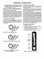
RULES FOR SAFE INSTALLATION
Carefully read and follow all safety instructions
manual or on pump
in this
This is the safety alert symbol. When you see this
symbol on your pump or in this manual, look for
one of the following signal words and be alert to the
potential for personal injury!
Warns about
ous personal
ignored.
cause serious personal
damage if ignored.
CAUTION
that will cause seri-
injury, death or major property
I'A_WARNINGIWarns
IA
hazards
] Warns
cause ",_or_er_sona_l
nored.
The worcr'NOTICE
whick are.important
about
hazards
injury, death
about
_iUry
hazards
that
damage
will
if
or can
or major property
that
or property
will
or can
damage
if ig-
- indicates
special
instructions
but not related to hazards.
1. To avoid risk of serious bodily injury and property
damage, read safety instructions
carefully before installing pump.
2. Follow local and/or national plumbing
cal codes when installing pump.
and electri-
3. Keep well covered while installing pump to prevent
leaves and other debris from falling into well, con,
taminating well and possibly damaging pump.
AND
OPERATION
4. Protect pump and piping system from freezing.
Allowing pump or water system to freeze could
severely damage pump and voids warranty.
IAWARNING[ To avoid serious
injury
and equipment
damage,
limit
system
pressure
to 100
pounds
per square
inch (PSI) or below
at all
times. Over-pressure
can cause tank blowup;
install relief valve capable
of passing
full pump volume at 100 PSI.
5. With a new well, test well for purity before use.
Consult local Health Department
for procedure.
IAwARNING [Hazardous
voltage.
cause death, or start fires.
6. Disconnect
electrical
power
stalling or working on pump.
Can shock,
source
burn,
before
in-
7. Ground pump with a ground wire run from grounding lug on motor to a grounded lead in the service
panel.
8. Line voltage and frequency of electrical power supply must agree with motor nameplate.
9. Use of fuses or wire smaller than size recommended
in owner's manual can cause overheating, possible
fires, and will void warranty.
10. This pump is a deep well jet pump. It is not designed or intended for shallow well use. Use in a
deep well (more than 25' depth to water).
MAJOR COMPONENTS
Tank and Air Volume
AND WHAT
Control
Adapter
The tank serves two functions:
1.
2.
Pressure
Relief Valve
Under certain conditions,
VMS pumps can generate
very high pressure. The pressure relief valve is installed
to make sure that the pressure in the system does not
exceed the pressure which the system can carry safely.
The pressure relief valve must be able to pass all the
water the pump can produce at the system's rated pressure. Install a relief valve (Sears Stock No. 27229) set
to open at 75 PSI. between
the pump and the tank.
There should be no shutoff valves between the pump
and the relief valve. See Figures 11 and 12, Page 8, for
more information.
stallation and operation.
A Captive _
tank maintains a constant precharge of
air in the tank and does not require an AVC. An annual
check on the tank pre-charge
pressure
is recommended.
Impeller
The pump's
impeller
rotates wit_ the motor shaft,
causing the water to fly-__md_y
centrifugal
force. The rotation of the impeller, along with the motion of the water, creates a vacuum at the center of the
impeller
(the "eye" of the impeller)
which pulls in
more water.
Pump
Mounting
The pump base has three equally spaced 3/4" NPT
threaded
sockets. These will take threaded
pipe for
legs, to allow enough room to make piping connections under the pump.
The Vertical Multi-Stage
O/MS) pump has two impellers; the water feeds through
them one after the
other, with each impeller adding to the pressure. This
allows the VMS jet pump to pull water from greater
depths and at a higher pressure than a conventional
single stage jet pumps.
In the case of a single pipe installation (see below), the
pump can be placed directly over the well, using the
offset nipple furnished with the casing adapter to connect the pump to the well head.
Piping
When installed on a 'double pipe' jet, one pipe is the
pressure or drive pipe; this pipe sends water down into
the well to the jet. The other pipe is the suction pipe;
this pipe carries water up to the pump suction from
the jet. Because of the pressure
requirements
and
depth of multi-stage
jet pump installations,
use the
chart below for pipe selection.
Jet
The jet is a nozzle/venturi
arrangement
installed in the
well which drives water up to the pump from the well,
boosting the water pressure going into the impellers.
The jet allows water to be lifted from a greater depth
than would be possible with only the impeller eye's
vacuum. In order to drive the jet, part of the discharge
stream from the pump is diverted
back _down the
hole" to the jet to help lift water from the well into the
pump suction.
When installed on a singe pipe jet, the well casing
serves as the drive pipe, carrying water to the jet. The
drop pipe inside the well is the suction pipe, carrying
water up to the pump from the jet.
Pressure Regulator
Pressure
Flange
The VMS pump is equipped
with an adapter flange.
This adapter facilitates installation and removal of the
pump without disturbing piping. See Pages 6 and 7 for
more information.
It provides a reservoir of water. Some of this water
is drawn offwhenever
a house fixture is opened (so
that the pump doesn't need to start every time you
open a tap).
It maintains a cushion of air under pressure.
A standard tank requires an Air Volume Control
(AVLO to add air to the tank when needed. See the
instructions included with the AVC for details of in-
The pressure regulator
vert the correct amount
most efficient operation.
pressure regulator may
pump's life (see Page
pump's efficiency.
THEY DO
Use a 'single pipe' system for a 2" or 3" well; use a 'double pipe' system for a 4 _ or larger well. See Pages 6 and
7 for details. Follow instructions
packed with jet package to get proper nozzle and venturi combination
for
your pumping depth.
is adjusted at installation
to diofwater back to the jet for the
Under certain conditions,
the
require adjustment
during the
10) to restore or maintain the
Use 1-1/4" pipe for both suction and drive pipes. A 1"
nipple, a 1-1/4_xl" facing bushing, and a 1-1/4" coupling are included in the jet package. These must be
used with the jet. (See Figure 8, Page 6, for installation
details.)
Switch
The pressure
switch automatically
starts the pump
when the pressure in the tank drops to 40 pounds per
square inch (PSI) and stops the pump when the tank
pressure reaches 60 PSI.
3
PUMP
PERFORMANCE
Multi-Stage
Pump Performance
Pump
Stock
No.
390.253251
1HP
(in gallons per minute)
Jet
Pkg.
No.
Discharge
Pressure
P.S.I.
40
60
70
80
29670*
4O
60
11.3
10.6
10.0
8.6
8.8
7.5
7.6
6.5
29902"*t
4O
60
11.7
11.0
11.1
9.5
10.2
8.6
29660***
40
60
11.7
11.0
11.1
9.5
10.2
8.6
Use 160 PSI Min. Rating Plastic
Pump
Pumping Depth In Feet
1_
110
120
140
1_
1_
6.5
5.5
5.0
4.8
5.0
4.8
5.0
4.7
4.2
3.9
3.5
2.7
2.0
1.5
9.2
7.8
7.8
6.6
6.4
5.4
5.1
4.7
5.0
4.6
4.5
4.2
4.0
3.4
3.2
2.6
2.1
1.7
9.2
7.8
7.8
6.6
6.4
5.4
5.1
4.7
5.0
4.6
4.5
4.2
4.0
3.4
3.2
2.6
2.1
1.7
Pipe.
* Jet Package
No. 29670 -
2" Single
Pipe (use 1-1/4" galvanized
pipe).
** Jet Package
*** Jet Package
No. 29902 No. :59__
3" S_ingle Pipe (use 1-1/4" galvanized
Pipe.
pipe).
1 Must be ordered
through
Sears
Product
Service,
1-800-366-7278.
4
210
INSTALLATION
Do not use on shallow wells!
(25 feet or less in depth)
!1:T
,hltl
Use New Pipe for Best Results.
, t
Deep well is more
than 25' (7.6M)
to water with
pump
running.
Clean Rowl
Well _
1
)
1O960697
From
Well
Casing _
Foot--._._
Valve
_'I _I
Figure I - No Dirt or Scale in Suction Pipe
822b 0697
Strainer_
Figure 5 - Use Pump On Deep Well Only
NOTICE: For proper performance,
pump MUST be
matched to ejector and to well depth. Use this pump
on wells 25' to 210' deep.
1.
1100 0697
Figure 2 - Foot Valve Must Work
2.
Freely
3.
4.
If Air Pockets Fon'n, Water Won't Flow.
Keep Pipe Straight and Angled up to Pump.
5.
6.
No air pockets in suction pipe.
No leaks in suction pipe. Use Teflon tape or PlastoJoint Stik to seal pipe joints.
7.
Match pump to well.
IMPORTANT: Flow into well must at least equal
flow out through pump!
Unions installed near pump and well will aid in servicing. Leave room to use wrenches.
1t01 _1_7
Figure 3 - No Air Pockets in Suction Pipe
No Air Leaks
in Suction Pipe.
8.
Pipe Joint
Compound Will
_Plastic.
If Air Flows
Water Won't
Use Teflon Tape.
!:igure
4 - Suction Pipe Must Not Leak
1102 0697
Long runs and many fittings increase friction and reduce flow. Locate pump as close to well as possible:
use as few elbows and fittings as possible.
Be sure well is clear of sand. Sand will plug the
pump and void the warranty.
Protect pump and all piping from freezing. Freezing
will split pipe, damage pump and void the warranty.
Check locally for frost protection
requirements
(usually pipe must by 12" below frost line and
pump must be insulated).
Be sure all pipes and foot valve are clean and in
good shape.
IA CAUTION I Motor normally operates at high temperature and will be too hot to touch. It is protected
from
heat damage during operation by an automatic internal
cutoff switch. Before handling pump or motor, stop
motor and allow it to cool for 20 minutes.
DEEP WELL
INSTALLATION
FOR DOUBLE
PIPE
Priming
Tee and
I
Gasket
Gasket
Suction: 1-1/4"
Coupling
Drive:
1-1/4" Pipe
Seal
orPipe
Plastic
---
1" Plastic Drive Pipe
1-1/4"
Cou
Plastic Pipe
Adapter. (Supplied with Ejector)
1" Plastic Pipe Adapter
--
Ejector Assembly
J
Drive Pipe
1-1/4" Plastic Suction Pipe
--
Pipe or Plastic
Pipe Adapter
1-1/4x1"
Face
Bushinc
1" Nipple
1386 1194
1461
Figure 6 - Offset Installation
Plastic Pipe Shown
Piping
In The
Figure 7 - Over the Well Installation
Steel Pipe Shown
Deep Well
the 1" tapped
7.
See Figures 6, 7, and 8.
NOTICE: Deep well installations are either single pipe
(2" wells) or double pipe (4" and larger wells). In a double pipe installation,
the larger pipe is the suction pipe
and the smaller pipe is the drive pipe (very deep wells
may use suction and drive pipes of the same diameter).
Plastic pipe is ideal for double pipe installations.
Due
to its light weight, it is easy to handle and does not usually require a block and tackle for installation
and removal.
Double
Pipe Installation
0195
- Plastic
hole in ejector
body (see Figure 8).
Install sufficient plastic pipe in well casing to place
ejector
at the proper
depth.
(Your well driller
should supply this information.)
NOTICE: As a guide, the ejector should be set at least
10 to 20 feet below the lowest water level with pump
running, if possible, but always at least five feet from
the bottom of the well.
8.
Tighten all hose clamps securely on plastic pipe.
Use two damps per joint to prevent air leaks into
suction pipe. Clamp screws should be on opposite
sides of the pipe. Fill pipes with water to make sure
that foot valve and connections
do not leak.
9.
Install sanitary well seal on top of well casing; use
steel nipple through well seal as shown in Figure 6.
Pipe
NOTICE: Use Teflon tape on all male threads on plastic pipe and fittings to prevent air leaks in suction piping.
Figure 8 - Jet Assembly With
I" and I - I/4" Drive Pipes
and ven-
NOTICE:
Align locating lugs on adapter flange and
pump base so that pump discharge will be aligned with
piping.
2. Inspect pipe for any foreign matter or obstructions.
NOTICE: Make sure that no foreign matter enters pipe
openings while installing pump.
3. Make sure foot valve operates freely: attach to ejector with a close nipple. Use Teflon tape on male
threads.
10. Install 1" nipple in one side of adapter flange. Slide
threadiess
coupling
down over drive pipe from
well. Thread adapter flange onto suction pipe from
well and align nipple and drive pipe.
11. Slide threadless coupling up and secure nipple to
drive pipe.
4.
Install nozzle
5.
Using Teflon tape on male threads, install special
plastic pipe adapter
(supplied
with ejector)
by
screwing adapter into 1-1/4" tapped hole in ejector
body (see Figures 6 and 8, above).
12. Remove paper backing from adhesive gasket. Apply
gasket to adapter flange, making sure that holes line
up.
1.
6,
Inspect ejector to make sure that nozzle
turi openings are dean and clear.
Thread
and venturi
in deep well ejector.
a 1" plastic pipe adapter
or a 1" nipple
into
13. Align locating lugs on pump base with locating lugs
on adapter flange; attach pump to flange with cap
screws provided.
DEEP WELL
INSTALLATION
FOR SINGLE
PIPE
Pump
mounted
on Casing
Adapter "%_
Pipe Clamp
serves
Drive
Water level
with pump
as
Pipe
Pipe Clamp.
Pipe
L
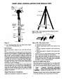
Figure I 0A - Use tripod
pipe into the well
10 to 20 Feet
and lever hoist to lower
Ej
,r
Cup
Leathers
5 Feet
or more
Figure
Figure 9
14. See "Discharge Pipe Sizes" for information
ing correct discharge pipe size.
Steel
a. Galvanized steel suction pipe.
b. Leather packer-type
ejector with
valve.
regard-
Piping
The special adapter nipple is not used with steel piping.
To more safely lower steel piping into the well, build a
tripod out of 2x4 lumber. A couple of pipe clamps can
also be made of 2x4s secured
with 1/2" bolts (see
Figure lOB). Always install the coupling at the top end
of the pipe joint and install the pipe clamp below the
coupling. This will prevent accidentally
dropping
the
pipe into the well if the clamp slips. With steel pipe,
be sure all joints are clean and the ends reamed before
installing; use teflon tape or pipe joint compound
at
each joint to prevent leakage.
Use a lever hoist (a "come-along")
to lower pipe into
well (see Figure 10A). As each section of piping is lowered into the well, fill it with water. This will help
prime the system and also serves as a check on leaks
which may occur in the piping and foot valve as the
piping is assembled.
Single
Pipe Ejector
Single pipe installations
1.
2.
built-in
foot
c. Turned couplings
(supplied
with packer-type
ejector).
d. Well casing adapter (supplied with packer-type
ejector).
Connect ejector to first length of pipe. Use pipe
joint compound
sparingly on male threads.
Lower pipe into casing. Use special turned couplings (included with single pipe ejector package)
to increase water flow. Use pipe joint compound
sparingly on male couplings threads.
Horizontal
Offset
Pipe Sizes
When the pump is set more than 25' to one side of the
well, increase the horizontal
pipe size to reduce friction. Never use pipe smaller than the pump port size.
Pump
Model
390.253251
Installation
require
10B - Pipe clamp detail
Up to 25'
Suct. Drive
25' to 100'
Suct. Drive
1-1/4" 1-1/4" 1-1/'Z' 1-1/4"
100' to 300'
Suct. Drive
2"
2"
NOTICE: Fill pipe with water as each length is added
to be sure foot valve and connections
do not leak.
(see Figure 9):
7
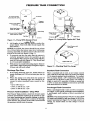
PRESSURE
Air Volume Control
Sears Stock No. 2761
lANK
I
_1
CONNECTION
To Service
_"_
"
_ (_
f_"-tax
I_ (J_
_._lb
y
Pump to Tank Piping
I1._.
1" Discharge --_
TANK
_"_-
_, J
_
J
TANK
Pressure
Regulator
,_j/j
Relief Valve Sears._-*_!_
Stock No. 27229
_.
r_
_j_-,_._
-_
_
Air Volume Control Tubing/Fdti_ "_ _
Sears Stock No. 27881
WellSeal
n_
_
j
__.
)
"_"_1,
•
'
"v,,,.Pressure
Regulator
AVC Fitting
Piping Tee and
"
Figure
3.
I I - Pump With
Standard
t
1" Service
Discharge
To
2355b 0697rm
2358b
Figure
Tank
Add lengths of pipe until the ejector reaches
proper depth. (Your well driller should supply
information.)
Relief Valve
0697nc
12 - Pump With
Captive-Ai#
Tank
the
this
Check Pressure with
Tire Gauge
NOTICE: As a guide, the ejector should be set at least
10 to 20 feet below the lowest water level with pump
running, if possible, but always at least 5 feet above the
bottom of the well (see Figure 9, Page 7).
4. - To properly
seat the cup seals, after the ejector is
correctly
positioned
move the assembly
up and
down slightly. Water pressure in the casing will then
soak the cup seals (see Figure 9). They should seal
in 2-3 hours after installation.
5.
With ejector set, install well casing adapter. Remove
pipe holder. Align locating lugs and tighten adapter
to form seal with well casing.
Discharge
Figure 13 - Checking Tank Pre-charge
Pipe Sizes
Standard
1.
If increasing discharge pipe size, install reducer in
pump discharge port. Do not increase pipe size by
stages.
2.
When the pump is set away from the points of
water use, the discharge
pipe size should be increased to reduce pressure
losses caused by friction.
When a standard tank is used, an air volume control
(AVC) adds air to the tank when it is needed. See Figure
11 for typical standard tank installation.
To connect
AVC to pump, thread a 1/8 _ compression
fitting into
tapped hole on the front of the pump. Cut tubing to
length to reach AVC; assemble to fitting on pump and
to AVC on tank. See installation instructions
provided
with tank and AVC for details.
• Upto 100 ft run: 1"
• 100 ft. to 300 ft run: 1-1/4"
• 300 ft. to 600 ft run: 1-1/2".
Pressure
Tank Installation
- Deep
Tank Connection
Precharged
Tank Connection
When a precharged
tank is used, no AVC is necessary.
See Figure 12 for typical precharged
tank installation.
A precharged
tank contains
a factory provided
air
charge.
Well
The Pressure Tank provides a reservoir of water under
pressure and maintains cushion of air pressure to prevent pipe hammering
and possible damage to plumbing components.
When water is drawn off through
house fixtures, the pressure in the tank is lowered and
the pressure switch starts the pump.
NOTICE: Your pump pressure switch is set for a 40-60
PSI range and requires a tank pre-charge
of 40 PSI for
proper operation (see Figure 13). See tank owner's air
charge. An annual check on tank charge is recommended.
8
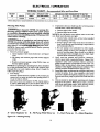
ELECTRICAL
Disconnect
power before working
on pump, motor, pressure
Your Motor Terminal Board (under the motor end cover)
and Pressure Switch look like one of those shown below,
Convert to 115 Volts as shown. Do not change motor wiring
ff line voltage is 230 Volts or if you have a single voltage
motor. Connect power supply as shown for your type of
switch and your supply voltage.
- Motor wires connect here.
-Power supply wires connecthere.
230 Volt: Connect 2 hot wires (black and red1
here and cap the white (neutral) wire. It does
notmatter whichwire goes to which screw.
115 Volt: Connect one hot wire (black or red)
to one of these screws (it doesnl matter
which one). Connect the white (neutral) wire
to the other screw. Cap any remaining
blackor red wires.
230 Volt to 115 Volt Conversion, Plug-in Type:
1. Pull plug
straight
out from
terminal
board;
switch, or wiring.
2. Plug in again
with arrow
on plug
pointingto
'115 Volts'.
2.
1.
Clamp the power cable to prevent strain
on the terminal screws.
Connect the green (or bare copper) ground wire
to the green ground screw.
Motor wires connect here.
230 Volt to 115 Volt Conversion,Spade Connector Type:
1.Move blackwire
from A to L1.
2. Move whitewire
with black tracer
from B to A.
supply wires connect here.
230 Volt: Connect 2 hot wires (black and red)
here and cap the white (neutral) wire. It does
not matter which wire goes to which screw.
115 Volt: Connect one hot wire (black or red)
to one of these screws (it doesn't matter
which one). Connect the white (neutral) wire
to the other screw. Cap any remaining
black or red wires.
3. Change Complete:
_Ground
Screw
) the powercable to prevent strain
on the terminal screws.
green (or bare copper) groundwire
to the green groundscrew.
Figure 14 - Motor
wiring connections
through
Pressure Switch. Match motor
Wiring
hazard.
Do not ground
voltage to line voltage.
with all local codes and ordinances
that apply. Consult
your local building inspector for code information.
IAWARNING I Hazardous
voltage.
Can shock, burn,
or kill. Connect
ground wire before
connecting
power supply wires. Use the wire size (induding
the ground wire) specified
in the wiring chart. If
possible, connect the pump to a separate branch circuit with no other appliances on it.
JA WARNING JExplosion
a gas supply line.
31870398
Connection
Procedure
1. Connect the ground wire first as shown in Figure 14.
The ground wire must be a solid copper wire at least
as large as the power supply wires.
to
.
There must be a solid metal connection
between
the
pressure switch and the motor for motor grounding
protection.
If the pressure switch is not connected
to the motor, connect the green ground screw in the
switch to the green ground screw under the motor
end cover. Use a solid copper wire at least as large
as the power supply wires.
Connections
I AWARNINGJFire hazard. Incorrect voltage can cause
a fire or seriously damage the motor and voids the warranty. The supply voltage must be within ±10% of the
motor nameplate
voltage.
.
NOTICE: Dual-voltage
motors are factory wired for
230 volts. If necessary,
reconnect
the motor for 115
volts, as shown. Do not alter the wiring in single voltage motors.
Install, ground, wire, and maintain your pump in compliance with the National Electrical Code (NEC) or the
Canadian
Electrical
Code (CEC), as applicable,
and
Connect the ground wire to a grounded lead in a service panel, to a metal underground
water pipe, to a
metal well casing at least ten feet (3M) long, or to a
ground electrode provided by the power company
or the hydro authority.
4. Connect the power supply wires
switch as shown in Figure 14.
9
to the pressure
ELECTRICAL
WIRING
CHART
/ OPERATION
- Recommended
MOTOR
HP
VOLTS
MAX. LOAD
AMPS
BRANCH FUSE*
RATING (AMPS)
1
115/230
19.2/9.6
25/I 5
Wire
and Fuse Sizes
DISTANCE IN FEET FROM MOTOR TO METER
0to50
10/14
51 to 100
10/12
101to200
8/10
I 201 to300
I
6/10
(*)Time delayfuse or circuitbreakers are recommendedin any motor circuit.
Priming
The
Pump
3.
]_,WARNING[Burn hazard.
NEVER run pump
dry.
Running
pump without
water may cause pump
to overheat,
damaging
seal and possibly
causing
burns to persons
handling
pump. Fill pump with
water before starting.
Remove
pressure
a. Close regulator
15A).
b. Fill pump
15B).
gauge.
valve (turn clockwise
and suction
pipe
c. Replace pressure
gauge,
thread; tighten gauge.
- see Figure
with water
using
Teflon
(Figure
tape
4.
on
NOTICE: If a priming tee and plug have been installed
for a long horizontal
run, be sure to fill suction pipe
through
this tee and replace plug. (Don't forget to
teflon tape the plug.)
2. Start Pump:
5.
Pressure should increase rapidly to 50 pounds per
square inch or more as ejector and pump prime. If
so, go to step 4, below.
.
If pressure does not build to 50 PSI, repeat steps a,
b, and c under Step No.1 two or three times to remove entrapped
air from the suction pipes.
A - Close Regulator
I_igure 15 - Priming
m
B - Fill Pump With
pump
b. Suction pipe has no leaks.
NOTICE: Air can leak in even where water won't leak
out. Make sure all joints are tight.
c. Control valve, check valve, or foot valve installed
and operating correctly.
{AWARNINGIRisk of explosion
and steam burns.
NEVER run pump with discharge
shut off, which
can boil water inside pump body. Steam in pump
may cause it to expkglr.,g__yone
near.
NOTICE: Open water system faucets before priming
pump for the first time.
1.
If pressure does not build up after priming
several times, check the following:
a. Suction pipe in the water.
Water
Pump
10
d. Pump trying to lift water more than rated lift for
deep well ejector used (including compensation
for horizontal offset).
e. Be sure pump is not airlocked. In offset installations, pump suction port should be highest
point in suction pipe; there should be no sags in
suction pipe (run it straight and at a slight angle
upward from well head to pump).
Once unit has primed
and pressure
stabilized,
slowly open (turn counterclockwiseFigure 16A,
regulator
valve until pressure
falters (pressure
gauge needle flutters; pump may become noisy - see
Figure 16B). At this point, close (turn clockwise)
regulator valve slightly until pressure stabilizes. This
setting provides maximum flow (Figure 16C).
Pump may draw well down far enough at this point
to lose its prime. If so, close regulator valve until
pressure is stable throughout
pumping cycle. Close
faucets and allow pump to pressurize tank and shut
off.
Check system by alternately
opening and closing
faucets in the system. With faucets open, pressure
will drop until pump starts; with faucets closed,
pressure will build up until pump shuts off.
C - Start
Pump _
D - Adjust
Regulator
OPERATION
.
I MAINTENANCE
There are conditions of deep well operation when
the regulator valve may be completely
open without any faltering of pressure.
In this case, operate
pump with regulator valve open.
HELPFUL
How
HINTS
To Handle
Using the Compound
If the pump or system seems to be operating
inefficiently, the compound
gauge can sometimes
help determine the problem.
I MAINTENANCE
A Gaseous
A compound
gauge is a combination
vacuum and pressure gauge which will indicate (1) receding water level
in the well, (2) leakage in the suction line or in the
pump, or (3) clogged impeller.
To use, install the gauge in the air volume control (AVC)
port in the base of the pump. Open all shutoff valves
between pump and household
piping. Tighten regulator screw as far as possible. After running pump a few
minutes to eliminate all air from pipes, loosen regulator screw until compound
gauge shows 15" of vacuum.
This setting indicates that the pressure regulator is set
for delivery of the highest volume of water possible.
Let the pump run a few minutes; if the water level in
the well is falling, the vacuum
will increase. If necessary, reduce the regulator setting to bring the vacuum
reading back to 15". If the pump does not develop 15"
of vacuum according the gauge, you may have air leaks
in the suction line or a clogged impeller.
Well
In some areas well water contains gases which must be
allowed to escape before the water is used. To deliver
gas-free water suspend a pipe, closed at the bottom and
open at the top, so that it surrounds
the suction pipe
inlet. (See Figure 17). Since the gases rise in the well
casing, the water sucked down through the pipe and
into the suction pump is free of gas. This type of well
must be vented to the outside of any enclosure.
Air
Control
In Flowing
Wells
Flowing wells or wells with little or no drawdown,
could create a special p__ti_ocitrol
in the operation of your standard tank system. In such cases, a
pre-charged
tank (which
needs no air control)
is
recommended.
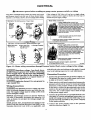
Cleaning
Figure
16A - Open
Regulator
Gauge
the Deep Well
Jet
1.
Disconnect
power.
2.
3.
4.
Disconnect
piping and well seal or casing adapter.
Withdraw jet assembly from the well.
Unscrew and remove the venturi. Remove the nozzle with a socket wrench and clean.
5.
Replace
all parts, reprime,
and turn on power.
Valve
Gases
rise to
sudace
wire to hold
pipesleeve
Figure 16B - Watch for Pressure Gauge to Flutter
pipe
valve
sleeve
cap
Figure
16C - Close Regulator
Pressure Stabilizes
Valve until
Figure
11
17 - Gas/Air
Control
in Well
MAINTENANCE
Pump
Diassembly
1.
Pull disconnect
switch.
from pressure switch.
2.
Remove the two cap screws holding the pump to
the flange adapter. Don't disturb the piping in the
well.
3.
Remove
surfaces
4.
Leaving the tubing in place, unscrew and remove
the straight barbed fitting at the pressure switch.
Draw a line down the side of the pump with a
marker to help alignment during reassembly. Mark
the pump from the motor to the base volute (see
Figure 18).
5.
the flange
clean.
Hold the motor shaft with pliers or vice grips
through the opening in the pump adapter. Unscrew
the impeller nut off the end of the shaft (see Figure
20).
.
Disconnect
adapter
gasket
power
and scrape
lines
the
Figure 20
.
Figure
.
The impellers are keyed to the shaft and do not unscrew. Insert two screw drivers on opposite sides
under the exposed
impeller and pry the impeller
off (Figure 21) to remove it.
18
Turn the pump upside down on the bench and
block it. Remove the four cap screws from the base.
With a mallet, tap upward on the base to loosen it.
Lift the base off of the intermediate
volute (see
Figure 19).
Figure 21
10. Carefully tap a small screwdriver
or thin bladed
chisel in between the intermediate
volute and the
pump adapter in two or three places around the
pump to separate the castings (Figure 22). Do not
mar the sealing surfaces; do not break pieces out
of the adapter or volute - the castings are easily
damaged
Figure
7.
19
To reduce the chance
your foot, lay it down
won't roll.
of dropping the pump onto
on the bench; block it so it
Figure 22
12
MAINTENANCE
11. Remove
the intermediate
volute
and slide the im-
Carefully
slide the adapter
over the shaft (see
Figure 24). Do not damage the shaft sealing surface;
it is highly polished and any slight scratches or nicks
will ruin it.
.
peller spacer off of the shaft.
12. Remove the impeller. Don't disturb the shaft keys if
you are only replacing the seal.
13. Rotate the seal spring retainer cup so that the slot
lines up with the shaft keys; remove the cup and
spring.
14. Remove the two cap screws holding the adapter
bracket to the motor.
Align
Marks
15. With two screwdrivers
on opposite
sides of the
pump, carefully pry the pump adapter away from
the motor. This will pull the seal off of the motor
shaft. Use caution to make sure that the ceramic
seal does not dig into the shaft
shaft's sealing surface.
Installation
1.
Clean
Of New
all gasket
and
scratch
the
before
re-
Seal
surfaces
thoroughly
Figure 24
assembly. Clean the __
in the pump
adapter.
2. Wet the rubber seat ring with soapy water and push
the stationary part of the seal into the seal bore cavity. Use a piece of 1" pipe pressing on a cardboard
washer
(to prevent
damaging
seal surface) as a
press. Make sure that the seal half is fully seated
in the seal bore cavity. Remove the cardboard once
. the seal is in place.
3. Make sure that the shaft keys are in place on the
shaft. If they are not, squeeze them in place now
with slip joint pliers. Do not tap them or hit them
with a hammer;
you could bend the shaft (see
Figure 23). When the keys are correctly installed,
the adapter will pass over the keys without interference.
.
.
Using the alignment marks made before disassembly, line up the adapter with the motor and bolt the
adapter in place. Tighten the cap screws evenly.
Push the shaft seal and seal spring onto the shaft,
after making sure that the seal faces and shaft are
dean. Take care that the shaft shoulder
does not
damage
the carbon
seal face. Follow the seal
spring with the spring holder; compress the spring
and give the spring holder a quarter turn to lock it
under the first shaft key (see Figure 25).
Figure 25
!
7.
Use plierswith care no hammers.
8.
Figure 23
13
Slide the first impeller onto the shaft; follow it with
the impeller spacer. Twist the impeller on the shaft
to make sure that the shaft key is still in place and
the impeller is locked to the shaft (the shaft should
turn with the impeller).
Install a new volute gasket, lining up the bolt holes
with the bolt holes in the adapter. Make sure the
gasket is right side up so that the water passage
holes line up with the water passages
in the volutes.
MAINTENANCE
9.
Install the intermediate
volute, aligning it with the
mark made before disassembly.
Use the long cap
screws to check this alignment.
It cannot
be
stressed too strongly that all bolt holes and water
passages of all gaskets and volutes MUST line up
with each other, or the pump
will not be assembled correctly.
10. Make sure the second shaft key is in place and install the second impeller.
Twist the impeller
to
make sure that the shaft key is still in place. Hold
the motor shaft with slip-joint pliers or vice-grips
and install and tighten
the impeller
locknut.
Tightening the lock nut automatically spaces the impeller correctly. Do not overtighten.
11. Install the base volute gasket. Make sure the gasket
is right side up so that the waterpassage
holes line
up with the water passages in the volutes. Install
the base volute, using the alignment
marks made
before disassembly.
Make sure that the pump discharge will correctly _ing
when the
pump is reinstalled.
12. Insert the four base capscrews
and tighten evenly
(see Figure 26). These should be easy to install if everything
is correctly
aligned. If not, don't force
them; go back over your work and find and correct the misalignment.
Bolts should
be easy to
insert.
Make sure
all marks
line up.
Figure 26
13. Reinstall the pressure
sure tube.
switch
barb fitting and pres-
14. Reinstall the pump on the adapter flange (use a new
gasket) and reconnect
the wiring and grounding.
Pump is now ready for operation.
14
TROUBLESHOOTING
SYMPTOM
POSSIBLE CAUSE(S)
CHART
CORRECTIVE ACTION
Motor will not run
1.
2.
3.
4.
Disconnect switch is off
Fuse is blown
Starting switch is defective
Wires at motor are loose, disconnected, or wired incorrectly
5. Pressure switch contacts are dirty
6. Wrong voltage
1.
2.
3.
4.
Motor runs hot and
overloadkicks off
1. Motor is wired incorrectly
2. Voltage is too low
1.
3. Pump cycles too frequently
3. See sectionbelowon too frequent cycling
"1. Pump in a new installation did not
pick up prime through:
a. Improper priming
b. Air leaks
c. Leaking foot valve
*2. Pump has lost its prime through:
a. Air leaks
b..JN_l_,_v_l_v
suction of
pump
1. In new installation
a. Re-prime according to instructions
b. Check all connections on suction line, air volume control, and ejector
c. Replace foot valve
2.
In installation already in use:
a. Check all connections on suction line, air volume control, ejector and shaft seal
b. Lower suction line into water and re-prime. If receding
water level in a shallow well operation exceeds suction
lift, a deep well pump is needed.
3.
Clean ejector or impeller; see Maintenance
4. Replace check valve or foot valve
Be sure switch is on
Replace fuse
Replace starting switch
Refer to instructions on wiring. Check and tighten all
wiring.
5. Clean by sliding piece of plain paper between contacts
6. Make sure motor voltage exactly matches power supply
voltage.
Refer to instructions
on wiring
2. Check with powercompany. Install heavierwiringif wire
size is too small.See wiringinstructions.
Motor runs but no
water is delivered
*(Note: Check
prime before looking for other
causes. Unscrew
pressure gauge
and see if there is
water in priming
hole)
3.
Ejector or impeller is plugged
4. Check valve or foot valve is stuck
in closed position
5. Pipes are frozen
6. Foot valve and/or strainer are
buried in sand or mud
5. Thaw pipes. Bury pipes below frost line. Heat pit or pump
house.
6. Raise foot valve and/or strainer above well bottom
Pump does not deliver water to full
capacity (Also
check point 3 immediately above)
1.
Water level in well is lower than estimated
2. Steel piping (if used) is corroded or
limed, causing excess friction
3. Offset piping is too small in size
1. Lower ejector in well
2. Replace with plastic pipe where possible, otherwise with
new steel pipe
Pump pumps water
but does not shut
off
1. Pressure switch is out of adjustment or contacts are "frozen"
2. Faucets have been left open
3. Ejector or impeller is clogged
4. Water level in well is lower than estimated
5. Wrong voltage
1. Adjust or replace pressure switch
3.
Use larger offset piping
2. Close faucets
3. Clean ejectoror impeller
4. Check possibilityof using a deep welljet pump
5. Make sure motorvoltageexactlymatches powersupply
voltage.
Pump cycles too
frequently
Air spurtsfrom
faucets
1. Standard pressure tank is waterlogged and has no air cushion
2. Pipes leak
3. Faucets or valves are open
4. Foot valve leaks
5. Pressure switch is out of adjustment
6. Air charge too low in Captive AiP
tank
1. Draintankto air volumecontroltapping. Check air volume
controlfor defects.Checkfor air leaksat any connection.
2. Check connections
3. Closefaucets or valves
4. Replacefoot valve
5. Adjustor replacepressureswitch
1.
2.
3.
4.
1.
2.
3.
4.
Pump is picking up prime
Leak in suction side of pump
Well is gaseous
Intermittent overpumping of well
6.
]5
Disconnectelectricalpowerand openfaucets untilall
pressureis relieved.Using automobile tire pressure
gauge,checkair pressurein tank at the valvestem locatedat top oftank. If lessthanthe pressureswitchcut-in
setting,pumpair intotank from outsidesourceuntilthe air
pressureis the same as cut-insetting of switch.Check air
valvefor leaks, usingsoapysolution,and replacecore if
necessary.
As soon as pump picks up prime, all air will be ejected
Check suction piping
Change installation, see Maintenance
Lower foot valve if possible, otherwise restrict discharge
side of pump
REPAIR PARTS
Multi-Stage
Jet Pump
.14C
--12
/
17
_--18
1281 0994
Pressure
Regulator
2
2O8O1095
1A
16
REPAIR PARTS
Repair Parts List - Multi-Stage
Key
No.
2
3
4
5
6
7
8
9
10
11
12
13
14
14A
14B
14C
15
16
17
18"
Part
Number
J218-600C
L43-5C
U36-112ZP
U217-1228
U37-672P
J212-24A
L2-16
U30-75ZP
U65-15SS
U 109-99
J24-11
J105-76P
J43-23
J101-26
J23-10
J23-11
U36-175D
J101-33
U78-57CT
U30-82ZP
Jet
Part
Description
Motor
Connector
Locknut- 1t2"
Pressure Switch
Switch Tube - 14-1/2"
Pressure Regulator Assembly
Adapter
Capscrew - 3/8"-16x1-1/4" Lg. (2 Req.)
Shaft Key (2 Req.)
Seal- Shaft
Spring Holder
Impeller (2 Req.)
Spacer- Impeller
Intermediate Volute w/Wear Rings
Gasket (2 Req.)
Wear Ring (2 Req.)
Wear Ring
Impeller Nut
Base Volute w/Wear Ring
Pipe Plug - 1/4" NPT
Capscrew - 3/8"-16x4-1/4" Lg. (4 Req.)
Repair Parts List - Pressure Regulator
NO.
Part
Number
1
1A
1B
2
2A
2B
2C
2D
2E
2F
3
4
5
6
7
8
9
10
Jl12-14
U111-212T
J66-16
J220-16B
J42-5
J62-9
J20-16
J43-31
U43-23ZP
U36-36ZP
U78-107DT
U239-3
J24-13
J61-5
J52-9
U30-60ZP
U30-69FTZP
U36-37ZP
Key
* Standard hardware item; may be
Part Description
Pressure Regulator Body w/Seat
Barbed Fitting - Elbow
Valve Seat
Diaphragm Assembly
Regulator Guide
Stem
purchased
locally.
** Notmailable;
specifyfreightor express.
Forrepairorservicetomotors,always
givetheMotorModelnumberandany
otherdatafoundonthemotormodel
plate.
This is a repair parts list, not
a packing list. Please order
by part number - not by key
number.
Diaphragm
Spring Follower
Lock Washer
Nut 1/4-20
Reducer Bushing 1/2x1/8 NPT
Pressure Gauge 0-100#
Spring
Spring Guide
Bonnet
Capscrew 5/16-18x3/4" Lg. (4 Req.)
Adjusting Screw 5/16-18x2"
Locknut 5116-18
17
To Order Parts,
Call Sears Product Service,
1-800-366-7278
REPAIR PARTS
Vertical
To Order Parts,
Casing Adapters
and Adapter
for Multi-Stage
Call Sears Product Service,
1-800-366-7278
T
Flanges
Jet Pump
1
2
3
4
5
489 0194
Adapter
Flange
Casing Adapter
Repair Parts List - Adapter Flange
Key
No.
Part
Number
1
2
J20-12
J2-17B
3*
U30-86PS
Part Description
Adapter Gasket
Adapter- 1-1/4")(1-1-1/4" NPT
1/2-13 x1-1/4" Long Capscrew (2 Req.)
* StandardHardwareItem,may be purchasedlocally.
Repair Parts List - Casing Adapters
Key
No.
1
2
3
4
5
6
7
8
9
J216-13
2"
U30-282ZP
J16-19ZZP
J21-19
J21-18
J51-1ZZP
U30-277ZP
J21-17
J16-20ZZP
U36-38ZP
J216-14
3"
U30-282ZP
J 16-2377
J21-19
J21-18
J51-377
U30-277ZP
J21-21
J 16-24ZZP
U36-38ZP
Part Description
3/8-16x5" Long Machine Bolt (2 Req.)
Upper Flange
Seal Ring - Drive Pipe
Seal Ring - Suction Pipe
Casing Adapter Body
3/8-16x2-1/2" Hex Hd. Bolt (3 Req.)
Seal Ring - Lower
Lower Flange
3/8" Hex Nut (3 Req.)
18
REPAIR PARTS
Jet Packages
2" and 3" Single Pipe Jets
4" Double
Pipe Jets
Suction Pipe
Drive
Seal
pple
Well
2
Pipe
I m
Adapter
3
1_11094
Repair Parts List1_o
10Q4
Key
No.
1359 1094
29670
2" Single
Pipe Jets
1
1
J32P-24
J32P-18
2
3
4
5
6
7
8
9
10
11
12
•
•
J34P-42
J40-24
J57-1
J43-14P
P122-10B
J66-13
Ul1-1
J37-4
J216-13
U37-116GP
29902
3" Single
Pipe Jets
J32P-24
J32P-18
J34P-42
J40-25
J57-3
J43-16
J43-20C
J161-3
J66-14
Jet Packages
29660
4" Double
Pipe Jets
J32P-24
J32P-18
J34P-42
Venturi
Venturi
Nozzle
N40-92
Jet Body
Packer Leathers (2 Req)
Spacer
Washer
Check Valve
Valve Seat
N212-12P
J37-4
L8-1P
U11-104P
B
J216-14
U37-116GP
Part
Description
m
Turned Coupling (11 included)
1" NPT Offset Nipple
Strainer
Plastic Pipe Adapter
Casing Adapter
1"x 6" T.O.E. Nipple
• Not illustrated.
Venturi Selection Chart
Max. Depth with Jet Package No.
Pump
Model
HP
390.253251
1
]9
Venturi
Installed
29670
2, Single
Pipe
29902
3" Single
Pipe
29660
4" Double
Pipe
J32P-24
J32P-18
90'
180'
100'
210'
100'
210'
OWNER'S
MANUAL
CRRFTSHRN°
MULTI-STAG
JET PUMP
Model No.
390.25325ol
Forthe repair or replacementparts youneed
Call7 am - 7 pro,7 daysa week
1-8OO-366-PART
(1-800-366-7278)
Forin-lwmemajorbrandrepairservice
Call24 hoursa day,7 daysa week
1-8OO-4-REPAIR
(1-800-473-7247)
The modelnumberof
your Multi-Stage Jet
Pumpwill be found on
the pump body.
When requesting service
or ordering parts, always
give the following
information:
• Product Type
• Model Number
• Part Number
• Part Description
Fw the locationof a
SearsRepairServiceCenterin yourarea
Call24 hoursa day,7 days a week
1-800-488-1222
ForInformationon purchasinga Sears
MaintenanceAgreementor to Inquire
aboutan existingAgreement
call9 am - 5 pm, Monday-Saturday
1-800-827-6655
SEARS
rtt_lY,.ll;£'l_;irllt]_
Amed_'s
Repair Specialists
Sears, Roebuck and Co., Hoffman
Estates, IL 60179
U.S.A.