1
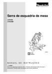
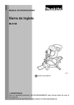
ENGLISH (Original Instruction Manual) Band Saw LB1200F INSTRUCTION MANUAL IMPORTANT: Read Before Using. SPECIFICATIONS Model Wheel size Max. cutting capacity LB1200F 305 mm 165 mm High 840 min-1 (50 Hz)/1,040 min-1 (60 Hz) Low 420 min-1 (50 Hz)/520 min-1 (60 Hz) 13.3 m/s (800 m/min) (50 Hz)/ High 16.7 m/s (1,000 m/min) (60 Hz) 6.7 m/s (400 m/min) (50 Hz)/ Low 8.3 m/s (500 m/min) (60 Hz) Circumference 2,240 mm x Width 6 mm, 13 mm, 16 mm 615 mm x 775 mm x 1,600 mm 560 mm x 400 mm 81.2 kg No load speed Cutting speed Blade size Overall dimensions Table size Net weight • Due to our continuing program of research and development, the specifications herein are subject to change without notice. • Specifications may differ from country to country. • Weight according to EPTA-Procedure 01/2003 Symbols END215-2 The following show the symbols used for the tool. Be sure that you understand their meaning before use. 3. .......... Read instruction manual. 4. .......... Withdraw the main plug. .......... Wear safety glasses. 5. .......... Do not place hand or fingers close to the blade. 6. .......... Only for EU countries Do not dispose of electric equipment together with household waste material! In observance of European Directive 2002/96/EC on waste electrical and electronic equipment and its implementation in accordance with national law, electric equipment that have reached the end of their life must be collected separately and returned to an environmentally compatible recycling facility. 7. 8. Intended use The tool is intended for cutting in wood. 9. Power supply The tool should be connected only to a power supply of the same voltage as indicated on the nameplate, and can only be operated on single-phase AC supply. They are double-insulated in accordance with European Standard and can, therefore, also be used from sockets without earth wire. 10. SAFETY INSTRUCTIONS 12. ENA001-2 WARNING: When using electric tools, basic safety precautions, including the following, should always be followed to reduce the risk of fire, electric shock and personal injury. Read all these instructions before operating this product and save these instructions. For safe operations: 1. Keep work area clean. Cluttered areas and benches invite injuries. 2. Consider work area environment. Do not expose power tools to rain. Do not use power tools in 2 11. 13. 14. damp or wet locations. Keep work area well lit. Do not use power tools where there is risk to cause fire or explosion. Guard against electric shock. Avoid body contact with earthed or grounded surfaces (e.g. pipes, radiators, ranges, refrigerators). Keep children away. Do not let visitors touch the tool or extension cord. All visitors should be kept away from work area. Store idle tools. When not in use, tools should be stored in a dry, high or locked up place, out of reach of children. Do not force the tool. It will do the job better and safer at the rate for which it was intended. Use the right tool. Do not force small tools or attachments to do the job of a heavy duty tool. Do not use tools for purposes not intended; for example, do not use circular saws to cut tree limbs or logs. Dress properly. Do not wear loose clothing or jewellery, they can be caught in moving parts. Rubber gloves and non-skid footwear are recommended when working outdoors. Wear protecting hair covering to contain long hair. Use safety glasses and hearing protection. Also use face or dust mask if the cutting operation is dusty. Connect dust extraction equipment. If devices are provided for the connection of dust extraction and collection facilities ensure these are connected and properly used. Do not abuse the cord. Never carry the tool by the cord or yank it to disconnect it from the socket. Keep the cord away from heat, oil and sharp edges. Secure work. Use clamps or a vice to hold the work. It is safer than using your hand and it frees both hands to operate the tool. Do not overreach. Keep proper footing and balance at all times. Maintain tools with care. Keep cutting tools sharp and clean for better and safer performance. Follow instructions for lubrication and changing accessories. Inspect tool cord periodically and if damaged have it repaired by an authorized service facility. Inspect extension cords periodically and replace, if damaged. Keep handles dry, clean and free from oil and grease. 15. Disconnect tools. When not in use, before servicing and when changing accessories such as blades, bits and cutters. 16. Remove adjusting keys and wrenches. Form the habit of checking to see that keys and adjusting wrenches are removed from the tool before turning it on. 17. Avoid unintentional starting. Do not carry a plugged-in tool with a finger on the switch. Ensure switch is off when plugging in. 18. Use outdoor extension leads. When tool is used outdoors, use only extension cords intended for outdoor use. 19. Stay alert. Watch what you are doing. Use common sense. Do not operate tool when you are tired. 20. Check damaged parts. Before further use of the tool, a guard or other part that is damaged should be carefully checked to determine that it will operate properly and perform its intended function. Check for alignment of moving parts, free running of moving parts, breakage of parts, mounting and any other conditions that may affect its operation. A guard or other part that is damaged should be properly repaired or replaced by an authorized service center unless otherwise indicated in this instruction manual. Have defective switches replaced by an authorized service facility. Do not use the tool if the switch does not turn it on and off. 21. Warning. The use of any accessory or attachment, other than those recommended in this instruction manual or the catalog, may present a risk of personal injury. 22. Have your tool repaired by a qualified person. This electric tool is in accordance with the relevant safety requirements. Repairs should only be carried out by qualified persons using original spare parts, otherwise this may result in considerable danger to the user. 12. NEVER wear gloves during operation. 13. Keep hands out of the line of the saw blade. 14. NEVER stand or permit anyone else to stand in line with the path of the saw blade. 15. Before using the tool on an actual workpiece, let it run for a while. Watch for vibration or wobbling that could indicate poor installation or a poorly balanced blade. 16. Replace the table insert when worn. 17. Connect band saw to a dust-collecting device when sawing wood. 18. Do not operate the machine when the door or guard protecting the saw band is open. 19. Take care that the selection of the saw band and the speed depends on the material to be cut. 20. Do not clean the saw band whilst it is in motion. ADDITIONAL SAFETY RULES FOR TOOL SAVE THESE INSTRUCTIONS. 1. 2. Wear eye protection. Don’t use the tool in presence of flammable liquids or gases. 3. Always use face or dust mask. 4. Check the blade carefully for cracks or damage before operation. Replace cracked or damaged blade immediately. 5. Use only saw blades recommended by the manufacturer and which conform to EN847-1. 6. Always use accessories recommended in this manual. Use of improper accessories such as abrasive cut-off wheels may cause an injury. 7. Select the correct saw blade for the material to be cut. 8. Do not use saw blades manufactured from high speed steel. 9. To reduce the emitted noise, always be sure that the blade is sharp and clean. 10. Do not cut metals such as nails and screws. Inspect for and remove all nails, screws and other foreign matter from the workpiece before operation. 11. Remove wrenches, cut-off pieces, etc. from the table before the switch is turned on. 3 Wheel Knob (For tensioning blade) Upper cover Knob (For securing upper housing door) Knob (For adjusting blade guide) Knob (For securing blade guide) Upper blade guide Blade Light switch Switch Rip fence Knob (For securing lower housing door) Knob (For tensioning V-belt) Lower cover Driving belt Carry Handle Wheel Stand Dust box Tire (Quick release) lever Knob (For adjusting cutter tool tracking) Grip (For adjusting table tilt) Lock lever (For securing table tilt) Dust extraction port 4 INSTALATION Securing the band saw stand If during operation there is any tendency for the band saw to tip over, slide or move, the band saw stand be secured to the floor. 1 2 Frame 3 4 5 • After attaching the stand, attach the handle and tires. Handle Washer Hex socket head bolt Tire 5 How to load dust box Securing hole Position hole Rail Rail Shoulder Dust box Plate spring 6 Shoulder The dust box is loaded from the underside of the table saw. When loading, insert plate spring (for securing) at inside edge of the machine’s positioning hole, slot both shoulders of dust box onto rails, and then slide toward the outside. Once the leading edge of the securing plate spring fits into the machine’s securing hole, the dust box is loaded. Secure table to trunnion using four hex bolts. Trunnion Table Hex bolts Hex bolts Pin is inserted at time of shipping, so please pull it out. Pin Table Installing the guide rail • Fasten the guide rail with four each thumb screws and washers to the table. Washer Thumb screw Guide rail 7 FUNCTIONAL DESCRIPTION Switch action Switch cover OFF switch Light switch CAUTION: • Before operation, make sure that the tool is turned on and off. The switch cover can be opened easily by sliding it upwards. To start the tool, press the ON (I) button. To stop it, press the OFF (O) button or the switch cover. Lighting up the lamps Push the upper position (I) of the switch for turning on the light and the lower position (O) for off. ON switch To start the tool, raise the switch lever. To stop it, lower the switch lever. ON Push stick Push stick The push stick serves as an extension of the hand and protects against accidental contact with the saw blade. The push stick must always be used if the distance between band saw blade and a rip fence is less than 150 mm. Guide the push stick at an angle of 20º ... 30º against the saw table’s surface. When the push stick is not used it can be stored on the push stick holder provided at the band saw frame. Replace push stick if damaged. Miter gauge Miter gauge The miter gauge is inserting into the table slot from the tables front edge. For miter cuts the miter gauge turns to 60º in both directions. For 45º and 90º miters positive stops are provided. To set a miter angle: loosen lock handle by turning it counter-clockwise. WARNING: When cutting with the miter gauge the lock handle must be firmly tightened. The auxiliary fence can be taken off and reversed after loosening knob. Knob Lock handle 8 Installing the Rip Fence The rip fence can be used on both sides of the blade. When the rip fence is moved from one side of the saw blade to the other the fence needs to reversed. Rip fence Reversing the fence Knob (A) 1. 2. 3. 4. 5. 6. 7. Fence Lock lever Fence holder Knob (B) Hold-down clamp Loosen knob (B) of the hold-down clamp. Remove hold-down clamp from the fence. Loosen knob (A). Lift fence off the fence holder. Reverse fence and slide back on the fence holder. Tighten knob (A). Slide hold-down clamp on the fence. Clamping the rip fence 1. 2. 3. 4. 5. Place rip fence on the guide rail. Tighten the lock lever of the rip fence. Loosen the knob (B) of the hold-down clamp. Slide hold-down clamp against the rear table edge. Tighten the knob (B). Fence height can be lowered when cutting thin materials. 1. Loosen knob (B) of the hold-down clamp. 2. Remove hold-down clamp from the fence. 3. Loosen knob (A). 4. Lift fence off the fence holder. 5. Slide knob (A) away from fence to remove. 6. Rotate fence 90º. 7. Insert knob (A) into the other groove of the fence. 8. Return fence to fence holder. 9. Tighten knob (A). 10. Slide hold-down clamp on the fence. When fence height has been lowered, the 0 (zero) point changes. If the rip fence is on the left side of the blade, slide the guide rail to the left to adjust to 0 point. 9 Guide rail ASSEMBLY Changing the band saw blade CAUTION: • Contacting the band saw blade even with the band saw blade at standstill may cause a personal injury. • Saw blade is dangerous. Be sure to wear gloves when handling saw blade in situations such as removing from packaging, mounting or replacing blade. 1. Loosen the two thumb screws for the right-guide rail, and slide the right-side rail to the right. Thumb screws 2. Open the upper cover and lower cover on the tool. 3. Hold the handle and pull the dust cover upwards to remove. Dust cover 10 Saw blade 4. Open the lower blade guard. 5. Set the upper blade guide to its lowest position. Saw housing Upper blade guide Lower blade guard 6. Loosen quick release lever until the band saw blade has slackened. 7. To remove the band saw blade, guide it through. - the slot in the saw blade. - the blade guard on the upper blade guides. - the blade cover on the saw housing. 8. Fit a fresh band saw blade. Observe correct position: the teeth point towards the front (door) side of the saw. 9. Center band saw blade on the rubber tyres of the band saw wheels. 10. Tighten quick release lever until blade does no longer slip off the band saw wheels. 11. Close lower blade guard. CAUTION: Close lower cover only when the lower blade guard is in its closed position. Quick release lever 12. Return the right-guide rail to its original position. 13. Fit the dust cover. 14. Close both covers. 15. Then: - tension band saw blade (Refer to the section titled “Tensioning the band saw blade” in “FUNCTIONAL DESCRIPTION”). - align band saw blade (Refer to the section titled “Aligning the band saw blade” “ASSEMBLY”). - align blade guides (Refer to the section titled “Adjusting the upper blade guide” in “FUNCTIONAL DESCRIPTION”). - let saw test run for at least one minute; - stop saw unplug and recheck settings. 11 Cutting speed adjustment Lower band saw wheel 1. Open the lower cover. 2. Slacken driving belt by turning the knob clockwise. 3. Put driving belt on the required pulley of the driving wheel (lower band saw wheel) and the corresponding motor pulley-note label inside the lower cover. CAUTION: The driving belt must run either on both front or both rear pulleys. Never have the Vbelt run diagonally. 8.3/6.7 m/s (500/400 m/min) 16.7/13.3 m/s (1,000/800 m/min) Motor pulley Setting knob for belt tension Knob With the setting knob the belt tension is corrected if necessary: - turning the setting knob clockwise reduces the driving belt tension. - turning the setting knob counter-clockwise increases the driving belt tension. Lower cover Tighten the driving belt again by turning the knob counter-clockwise (half-way between the pulleys the driving belt should flex approx. 10 mm). Close the lower cover. Motor pulley Driving belt approx. 10 mm 12 Pulley of the driving wheel FUNCTIONAL DESCRIPTION Tensioning the Band saw Blade Knob CAUTION: Too much tension can cause the band saw blade to break. Too little tension can cause the driven band saw wheel to slip and the band saw blade to stop. Upper blade guide 1. Raise upper blade guide fully. Using the scale as guide, and taking the blade width into consideration, turn the knob to adjust tension. (After adjusting, check tension as shown in item 2.) 2. Checking the blade tension: - check tension by pushing with a finger, halfway between table and upper blade guide, against the side of the blade (the blade should flex not more than 12 mm) - check adjustment at the blade tension indicator. The scale indicates the correct adjustment in dependence on the band saw blade width. 3. Correct tension if necessary: - turning the setting knob clockwise increases the blade tension. - turning the setting knob counter-clockwise reduces the blade tension. Aligning the band saw blade Lock knob Knob If the band saw blade does not run in the center of the rubber tyres, the tracking needs to be corrected by adjusting the tilt of the upper band saw wheel: 1. Loosen lock knob. 2. Manually rotate the upper wheel, taking care not to touch the blade. 3. Turn setting knob clockwise if the band saw blade runs towards the front of the saw. - turn setting knob counter-clockwise if the band saw blade runs toward the rear of the saw 4. After adjusting, always close the lock knob. 13 Quick release lever Quick release lever With the quick release lever the saw blade tension is released. Clockwise: Reduce tension Counterclockwise: Increase tension Upper blade guide adjustment Adjusting knob Lock knob The height of the upper blade guide needs to be adjusted: prior to every cutting/operation, to accommodate the height of the work piece (the upper blade guide should be set approx. 3 mm above the work piece); - after adjustments of band saw blade or saw table (e.g. band saw blade change, tensioning of the band saw blade, saw table alignment). CAUTION: Before adjusting the upper blade guide and saw table tilt: - switch machine OFF; - wait until the band saw blade has come to a complete stop. Upper blade guide 14 • Set upper blade guide with the adjusting knob to the desired height by loosening the lock knob. After adjustment be sure to tighten the lock nut. • Never cut several work pieces at the same time — and also no bundles containing several individual pieces. Risk of personal injury if individual pieces are caught by the saw blade uncontrolled. 1. Loosen bolt C, and adjust bearing holder, so that guide bearing is positioned 1 or 2 mm from bottom of blade. 2. Loosen bolt A, and adjust thrust bearing to a position of 0.5 mm from rear of blade. 3. Loosen bolt B, and adjust guide bearing to a position 0.5 mm away from blade. Guide bearing Bolt A 0.5 mm 1 - 2 mm Guide bearing distance from bottom of blade Bolt C 0.5 mm Bolt B Guide bearing Bearing holder Thrust bearing Bolt A Blade 15 Align the lower blade guide The lower blade guide consists of: - a thrust bearing (supporting the band saw blade from the rear). - two guide bearings (providing lateral support). These parts need to be readjusted after every band saw blade change or tracking adjustment: Bolt A Thrust bearing Hex bolt Note: Periodically check thrust bearings and guide bearings for wear, if necessary replace both guide bearings at the same time. • Open lower cover door and the lower blade guard. • Loosen hex bolt, move the entire lower blade guide, and adjust the guide bearing to a position of 1 or 2 mm from bottom of individual blade. Adjusting the thrust bearing 1. Loosen bolt A. 2. Adjust thrust bearing position (distance thrust bearing - band saw blade = 0.5 mm — if the band saw blade is turned by hand, it must not touch the thrust bearing). 3. Tighten bolt A. Adjusting the guide bearings Guide bearing Bolt B 1. Loosen bolt B. 2. Set guide bearing against the band saw blade. 3. Turn the band saw wheel by hand in a clockwise direction several times to bring the guide bearings in correct position. Loosen bolt A, and adjust thrust bearing to a position of 0.5 mm from rear of blade. Both guide bearings should JUST TOUCH the band saw blade. 4. Tighten bolt B again. 5. Close lower blade guard. 6. Close the lower cover door. Aligning the saw table at right angles to the band saw blade Screw 16 1. Raise upper blade guide fully (see “Operation”). 2. Check band saw blade tension (see “FUNCTIONAL DESCRIPTION”). Turn the handle clockwise to tilt the table in an anticlockwise direction, and turn the handle anticlockwise to tilt the table in a clockwise direction. 3. Loosen lock lever. 4. Using a try square, set the table at right angles to the blade by turning the handle to adjust the table, and tighten the lock lever again. 5. Adjust limit stop screw until it touches the saw housing. Lock lever Operation Danger: To reduce the risk of personal injury as much as possible, the following safety recommendations should be observed when operating the saw. • • • • • • • • • • • CAUTION: Do not touch the saw blade when cutting. During saw operation, wear safety glasses, but do not wear gloves. Cut only one work piece at a time. Always hold the work piece down on the table. Do not jam any work pieces. Do not try to slow the band saw blade down or stop it by pushing the work piece against the saw blade from the side. When straight cutting against the fence use a push stick. If the type of work requires, use the following: - pushing stick — if distance rip fence - band saw blade 150 mm; - work support — for long stock, which would otherwise fall off the table on completion of the cut; - dust collector; - when cutting round stock, firmly secure material as shown in diagram. - a suitable guide for firm support when cutting thin stock layed on edge. - gloves for handling the saw band and rough material. Before starting work, check to see that the following are in proper working order: - band saw blade; - upper and lower blade guard. Replace damaged parts immediately. Assume correct work position (the band saw blade’s teeth must point towards the operator). 17 Sawing WARNING: Risk of kickback (work piece is caught by the band saw blade and thrown against the operator.) Do not jam any work piece. • Select rip fence and table tilt for the type of cutting operation to be carried out. • Set upper blade guide 3 mm above the work piece. Note: Always make a trial cut in a piece of scrap to verify settings, correct if necessary before cutting the work piece. • Place work piece on the saw blade. • Plug in. • Start saw. • Cut work piece in a single pass. • Switch off if no further cutting is to be done immediately afterwards. • Use separately retailed sub table. Saw table tilt Table CAUTION: When bevel-cutting with the table inclined, place the guide on the lower part of the table. After loosening the lock lever the saw table tilts steplessly through 47º against the blade. Turn the handle clockwise to tilt the table in an anticlockwise direction, and turn the handle anticlockwise to tilt the table in a clockwise direction. Lock lever Handle Connecting to vacuum cleaner Cleaner operations can be performed by connecting the tool to Makita vacuum cleaner or dust collector. If a dust extractor is fitted to the large opening collector, rearrange dust collector to ensure it has a large opening. Nut Large opening collector Small opening collector 18 Small dust collector Large dust collector (Mounted on main unit) (For changeover) How to move machine • Raise handle to enable movement of machine. • During transportation the saw band guard should be fully down and close to the table. • Do not use guarding for handling or transportation. Carry Handle CAUTION: • If handle is raised too high, the machine may topple over. MAINTENANCE CAUTION: • Always be sure that the tool is switched off and unplugged before attempting to perform inspection or maintenance. NOTICE: • Never use gasoline, benzine, thinner, alcohol or the like. Discoloration, deformation or cracks may result. Cleaning Clean out sawdust and chips from time to time. Carefully clean the blade guard and moving parts inside the band saw. Lubrication To keep the band saw in tip-top running condition, and to assure maximum service life, oil or grease the moving parts and rotating parts from time to time. To reduce the emitted noise, always be sure that the blade is sharp and clean. To maintain product SAFETY and RELIABILITY, repairs, any other maintenance or adjustment should be performed by Makita Authorized Service Centers, always using Makita replacement parts. ACCESSORIES CAUTION: • These accessories or attachments are recommended for use with your Makita tool specified in this manual. The use of any other accessories or attachments might present a risk of injury to persons. Only use accessory or attachment for its stated purpose. If you need any assistance for more details regarding these accessories, ask your local Makita Service Center. • • • • • • • Band saw stand Hex wrench Rip fence Miter gauge Circular ruler Extension table Sanding belt attachment 19 Makita Corporation JM21080008 ALA www.makita.com