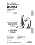
1
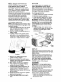
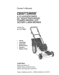
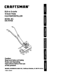
Owner's Manual
IC..FTSMnWl
ROTARY LAWN MOWER
6.75 Horsepower
Power-Propelled
21" Multi-Cut
Model No.
917.377110
• EspaSol, p. 20
CAUTION:
Read and follow all
Safety Rules and Instructions
before operating this equipment
Sears, Roebuck and Co., Hoffman Estates,
Visit our Craftsman website: www.sears.com/craftsman
IL 60179
U.S.A.
Maintenance ......................................
Service and Adjustments ...................
Storage ..............................................
Troubleshooting .................................
Repair Parts .......................................
Sears Service .......................... Back
Warranty ...................................................
2
Safety Rules ..........................................
2-4
Product Specifications .............................. 4
Assembly / Pre-Operation ..................... 5-6
Operation ............................................
7-11
Maintenance Schedule ........................... 12
12-15
15-17
17-18
18-19
38-47
Cover
LIMITED TWO YEAR WARRANTY ON CRAFTSMAN POWER MOWER
For two years from date of purchase, when this Craftsman Lawn Mower is maintained,
lubricated, and tuned up according to the operating and maintenance instructions in the
owner's manual, Sears will repair free of charge any defect in material or workmanship.
If this Craftsman Lawn Mower is used for commercial
applies for only 90 days from the date of purchase.
or rental purposes, this warranty
This Warranty does not cover:
• Expendable items which become worn during normal use, such as rotary mower
blades, blade adapters, belts, air cleaners and spark plug.
• Repairs necessary because of operator abuse or negligence, including bent crankshafts and the failure to maintain the equipment according to the instructions contained in the owner's manual.
Warranty service is available by returning the Craftsman power mower to the nearest Sears
Parts & Repair Center in the United States. This warranty applies only while this product
is used in the United States.
This Warranty gives you specific legal rights, and you may also have other rights which
vary from state to state.
Sears,
Roebuck
And Co., D/817 WA, Hoffman
Estates,
IL 60179
IMPORTANT: This cutting machine is capable of amputating hands and feet and throwing objects. Failure to observe the following safety instructions could result in serious
injury or death.
Ai_WARNING: Battery posts, terminals and
related accessories contain lead and lead
compounds, chemicals known to the State
of California to cause cancer and birth
defects or other reproductive harm. Wash
hands after handling.
• 1,CAUTION: Muffler and other engine
parts become extremely hot during
operation and remain hot after engine has
stopped. To avoid severe burns on contact,
stay away from these areas.
_¢l,Look for this symbol to point out
important safety precautions. It means
CAUTION!H
BECOME ALERT!H
YOUR SAFETY IS INVOLVED.
• I,WARNING: In order to prevent accidental starting when setting up, transporting, adjusting or making repairs,
always disconnect spark plug wire and
place wire where it cannot come in contact with plug.
A_,WARNING: Engine exhaust, some of its
constituents, and certain vehicle components contain or emit chemicals known
to the State of California to cause cancer
and birth defects or other reproductive
harm.
2
I. GENERAL
OPERATION
• Read, understand, and follow all
instructions on the machine and in the
manual(s) before starting. Be thoroughly
familiar with the controls and the proper
use of the machine before starting.
• Do not put hands or feet near or under
rotating parts. Keep clear of the discharge opening at all times.
• Only allow responsible individuals, who
are familiar with the instructions, to operate the machine.
• Clear the area of objects such as rocks,
toys, wire, bones, sticks, etc., which
could be picked up and thrown by the
blade.
• Be sure the area is clear of other people
before mowing. Stop machine if anyone
enters the area.
• Do not operate the mower when barefoot or wearing open sandals. Always
wear substantial foot wear.
• Do not pull mower backwards unless
absolutely necessary. Always look down
and behind before and while moving
backwards.
• Do not operate the mower without
proper guards, plates, grass catcher or
other safety protective devices in place.
• See manufacturer's instructions for
proper operation and installation of
accessories. Only use accessories approved by the manufacturer.
• Stop the blade(s) when crossing gravel
drives, walks, or roads.
• Stop the engine (motor) whenever you
leave the equipment, before cleaning the
mower or unclogging the chute.
• Shut the engine (motor) off and wait until
the blade comes to complete stop before
removing grass catcher.
• Mow only in daylight or good artificial
light.
• Do not operate the machine while under
the influence of alcohol or drugs.
• Never operate machine in wet grass.
Always be sure of your footing: keep a
firm hold on the handle and walk; never
run.
• Disengage the self-propelled mechanism or drive clutch on mowers so
equipped before starting the engine
(motor).
• If the equipment should start to vibrate
abnormally, stop the engine (motor) and
check immediately for the cause. Vibration is generally a warning of trouble.
• Always wear safety goggles or safety
glasses with side shields when operating
mower.
II. SLOPE OPERATION
Slopes are a major factor related to slip
and fall accidents which can result in
severe injury. All slopes require extra caution. If you feel uneasy on a slope, do not
mow it.
DO:
• Mow across the face of slopes: never
up and down. Exercise extreme caution
when changing direction on slopes.
• Remove obstacles such as rocks, tree
limbs, etc.
• Watch for holes, ruts, or bumps. Tall
grass can hide obstacles.
DO NOT:
• Do not trim near drop-offs, ditches or
embankments. The operator could lose
footing or balance.
• Do not trim excessively steep slopes.
• Do not mow on wet grass. Reduced footing could cause slipping.
III. CHILDREN
Tragic accidents can occur if the operator
is not alert to the presence of children.
Children are often attracted to the machine
and the mowing activity. Never assume
that children will remain where you last
saw them.
• Keep children out of the trimming area
and under the watchful care of another
responsible adult.
• Be alert and turn machine off if children
enter the area.
• Before and while walking backwards,
look behind and down for small children.
• Never allow children to operate the machine.
• Use extra care when approaching blind
corners, shrubs, trees, or other objects
that may obscure vision.
IV. SERVICE
• Use extra care in handling gasoline and
other fuels. They are flammable and
vapors are explosive.
- Use only an approved container.
- Never remove gas cap or add fuel
with the engine running.
Allow engine to cool before refueling.
Do not smoke.
- Never refuel the machine indoors.
- Never store the machine or fuel
container inside where there is an
open flame, such as a water heater.
• Never run a machine inside a closed area.
• Never make adjustments or repairs with
the engine (motor) running. Disconnect the
spark plug wire, and keep the wire away
3
from the plug to prevent accidental starting.
• Keepnuts and bolts, especially blade
• Grasscatchercomponentsare subject
attachmentbolts, tight and keepequipto wear, damage,and deterioration,
ment in good condition.
which could expose moving parts or
• Nevertamperwith safetydevices.Check
allow objectsto be thrown.Frequently
their proper operationregularly.
check componentsand replacewith
• Keep machine free of grass, leaves, or
manufacturer'srecommendedparts,
otherdebrisbuild-up.Cleanoilorfuelspillwhen necessary.
age.Allow machineto coolbeforestoring. • Mowerbladesare sharp and can cut.
• Stop and inspectthe equipmentif you
Wrap the blade(s)or wear gloves,and
strike an object. Repair,if necessary,
use extra caution when servicingthem.
before restarting.
• Do not changethe enginegovernorset• Neverattempttomakewheelheightadjustting or overspeedthe engine.
mentswhilethe engine(motor)is running.
Serial Number:
Date of Purchase:
GasolineCapacity/Type:
1.6 Quarts (Unleaded Regular)
Oil Type (API-SF-SJ):
SAE 30 (above 32°F); SAE 5W-30 (below 32°F)
Oil Capacity:
20 Ounces
Spark Plug (Gap: .030")
Champion RJ19LM or J19LM
Blade Bolt Torque:
35-40 ft. Ibs.
• The model and serial numbers will be found on a decal on the rear of the lawn mower
housing. Record both serial number and date of purchase in space provided above.
Repair Protection
Congratulations on making a smart purchase. Your new Craftsman® product is
designed and manufactured for years of
dependable operation. But like all products, it may require repair from time to
time. That's when having a Repair Protection Agreement can save you money and
aggravation.
Fast help by phone - phone support
from a Sears technician on products
requiring in-home repair, plus convenient repair scheduling.
Once you purchase the Agreement, a
simple phone call is all that it takes for you
to schedule service. You can call anytime
day or night, or schedule a service appointment online.
Sears has over 12,000 professional repair
specialists, who have access to over 4.5
million quality parts and accessories.
That's the kind of professionalism you can
count on to help prolong the life of your
new purchase for years to come. Purchase
your Repair Protection Agreement today!
Some limitations
and exclusions apply.
For prices and additional information
call 1-800-827-6655.
Purchase a Repair Protection Agreement
now and protect yourself from unexpected
hassle and expense.
Here's what's included in the Agreement:
•
•
•
•
Agreements
Expert service by our 12,000 profesional repair specialists.
Unlimited service and no charge for
parts and labor on all covered repairs.
Product replacement if your covered
product can't be fixed.
Discount of 10% from regular price of
service and service-related parts not
covered by the agreement; also, 10%
off regular price of preventive maintenance check.
Sears
Installation
Service
For Sears professional installation of home
appliances, garage door openers, water
heaters, and other major home items, in
the U.S.A. call 1-800-4-MY-HOME®.
4
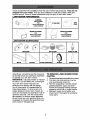
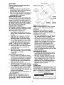
These accessories were available when this lawn mower was produced. They are not
shipped with your mower. They are also available at most Sears retail outlets and
service centers. Some of these accessories may not apply to your lawn mower.
LAWN MOWER PERFORMANCE
CLIPPING
FOR
REAR
DEFLECTORS
DISCHARGE
LAWN MOWERS
___
\\
_\\
\\\
LAWN MOWER
STABILIZER
GRASS CATCHERS
FOR
GRASS CATCHERS
FOR
LAWN MOWERS
REAR DISCHARGE
LAWN MOWERS
SIDE DISCHARGE
MAINTENANCE
MUFFLERS
BELTS
AIR FILTERS
BLADES
BLADE ADAFq'ERS
Read these instructions and this manual in
its entirety before you attempt to assemble
or operate your new lawn mower.
IMPORTANT: This lawn mower is shipped
WITHOUT OIL OR GASOLINE in the engine.
Your new lawn mower has been assembled at the factory with the exception of those parts left unassembled for
shipping purposes. To ensure safe and
proper operation of your lawn mower, all
parts and hardware you assemble must be
tightened securely. Use the correct tools
as necessary to ensure proper tightness.
All parts such as nuts, washers, bolts, etc.,
necessary to complete the assembly have
been placed in the parts bag.
SPARK PLUGS
WHEELS
ENGINE OIL
TO REMOVE LAWN MOWER FROM
CARTON
1. Remove loose parts included with mower.
2. Cut down two end corners of carton
and lay end panel down flat.
3. Remove all packing materials except
padding between upper and lower
handle and padding holding operator
presence control bar to upper handle.
4. Roll lawn mower out of carton and
check carton thoroughly for additional
loose parts.
5
TO ASSEMBLE GRASS CATCHER
1. Slide grass catcher bag over the frame.
Make sure the rear handle is on top
(the same side as the front handle) and
the strap is on the bottom.
2. Slip vinyl bindings over frame.
NOTE: If vinyl bindings are too stiff, hold
them in warm water for a few minutes. If
bag gets wet, let it dry before using.
3. Close grass catcher door.
NOTE" When fully closed, door will "snap"
shut over frame and vinyl bindings.
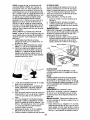
HOWTO SET UPYOUR LAWN MOWER
TO UNFOLD HANDLE
IMPORTANT: Unfold handle carefully so
as not to pinch or damage control cables.
1. Raise lower handle section to operating position and align hole in handle
with one of the height positioning holes
in handle bracket.
2. Insert handle bolt through handle and
bracket and secure with knob.
3. Repeat for opposite side of handle.
4. Remove protective padding, raise upper handle section into place on lower
handle and tighten both handle knobs.
5. Remove any packing material from
around control bar.
Your lawn mower handle can be adjusted
for your mowing comfort. Refer to "ADJUST HANDLE" in the Service and Adjustments section of this manual.
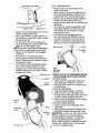
iiii
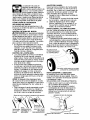
Operator presence
control bar
Front
LIFT
UF
Mowing
position
Bolt
Knob
Vinyl
Handle"
bracket
s j
TO INSTALL
6
ATTACHMENTS
Your lawn mower was shipped ready to be
used as a mulcher. To convert mower to
bagging or discharging, see '%0 CONVERT MOWER" in the Operation section
of this manual.
KNOWYOUR
LAWN MOWER
READ THIS OWNER'S MANUAL AND ALL SAFETY RULES BEFORE OPERATING
YOUR LAWN MOWER, Compare the illustrations with your lawn mower to familiarize
yourself with the location of various controls and adjustments, Save this manual for
future reference,
These symbols may appear on your lawn mower or in literature
product. Learn and understand their meaning.
CAUTION
OR WARNING
ENGINE
ON
ENGINE
OFF
FAST
SLOW
CHOKE
FUEL
supplied with the
OIL
DANGER, KEEP HANDS
AND FEET AWAY
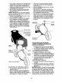
Operator presence control bar
Drive control lever
Starter
handle'
knob
fne of] cap with dipstick
Grass
catcher
Muffler
Dual
point
height
adjuster
lever
Gasoline fi]ler oaf
Air filter
Mulcher door
Primer
IMPORTANT:
This lawn mower
is shipped
WITHOUT
OIL OR GASOLINE
Housing
in the engine.
MEETS CPSC SAFETY REQUIREMENTS
Sears rotary walk-behind power lawn mowers conform to the safety standards of the
American National Standards Institute and the U.S, Consumer Product Safety Commission, The blade turns when the engine is running,
Operator presence control bar - must
be held down to the handle to start the
engine. Release to stop the engine,
Primer - pumps additional fuel from the
carburetor to the cylinder for use when
starting a cold engine.
Starter handle- used for starting engine.
Drive control lever - used to engage
power-propelled forward motion of mower,
Mulcher door - allows conversion to
discharging or bagging operation.
Dual point height adjuster - used to
adjust cutting height of lawn mower.
7
• To keep drive control engaged when
turning corners, push down on the
handle to lift the front wheels off the
ground while turning lawn mower.
DRIVE CONTROL ADJUSTMENT
The operation of any lawn
mower can result in foreign
objects thrown into the
eyes, which can result in
severe eye damage. Always
wear safety glasses or eye shields while
operating your lawn mower or performing
any adjustments or repairs. We recommend a standard safety glasses or wide
vision safety mask worn over spectacles.
HOWTO USEYOUR
ENGINE
Over time, the drive control system may become "loose", resulting in decreased speed.
There is a button on the u nderside of the drive
control housing to increase tension on the
drive cable. Proceed as follows:
1. Turn mower engine off and disconnect
spark plug wire from spark plug.
2. Pull out button on underside of drive
control, then push it back in.
3. Operate mower to see if drive speed
has increased. If there is no increase,
the drive belt is worn and needs to be
replaced.
TO ADJUST CUTTING HEIGHT
LAWN MOWER
SPEED
The engine speed was set at the factory
for optimum performance. Speed is not
adjustable.
ENGINE ZONE CONTROL
_L,CAUTION: Federal regulations require
an engine control to be installed on this
lawn mower in order to minimize the
risk of blade contact injury. Do not under
any circumstances attempt to defeat the
function of the operator control. The blade
turns when the engine is running.
* Your lawn mower is equipped with an
operator presence control bar which
requires the operator to be positioned
behind the lawn mower handle to start
and operate the lawn mower.
DRIVE CONTROL
, Self-propelling is controlled by holding the operator presence control bar
down to the handle and pulling the drive
control lever rearward to the handle.
The farther toward the handle the lever
is pulled, the faster the unit will travel.
* Forward motion will stop when either
the operator presence control bar or
drive control lever are released. To stop
forward motion without stopping engine,
release only the drive control lever. Hold
operator presence control bar down
against handle to continue mowing
without self-propelling.
NOTE: If after releasing the drive control
the mower will not roll backwards, push
the mower forward slightly to disengage
drive wheels.
Both front wheels are adjusted by a single
lever on the left front wheel. Likewise,
both rear wheels are adjusted by a single
lever on the left rear wheel.
° Pull adjuster lever toward wheel. To
raise mower, move lever forward to
desired position. To lower mower, move
the lever backward to desired position.
Be sure to adjust both front and rear
wheels to the same height.
Height
LEVER BACKWARD
TO LOWER MOWER
LEVER FORWARD
TO RAISE MOWER
TO CONVERT
TO
ENGAGE
DRIVE
CONTROL
MOWER
Your lawn mower was shipped ready to
be used as a mulcher. To convert to rear
bagging or side discharging:
_=ratorpresence control bar
Adjustrner_t
button (or_
ur_dersfde)
usterlever
REAR BAGGING
• Remove knob securing mulcher door to
lawn mower housing.
° Open mulcher door and insert tabs
of discharge chute into hinge bracket
opening and position rear of chute over
threaded stud.
Drive
control
lever
DRIVE
CONTROL
DISENGAGED
8
Hfr_ge bracket
SIDE DISCHARGING
° Grass catcher and discharge chute
must be removed.
° Open mulcher door and install front of
side discharge deflector beneath door
and position rear over threaded stud.
° Secure rear of side discharge deflector
to lawn mower housing with knob.
° Mower is now ready for side discharging
operation.
° To convert to mulching operation, side
discharge deflector must be removed
and mulcher door secured to mower
housing with knob.
° To convert to rear bagging operation, side discharge deflector must be
removed; discharge chute and grass
catcher installed and discharge chute
secured to mower housing with knob.
Muloher door
° Secure rear of discharge chute to lawn
mower housing with knob.
° Place rear handle of grass catcher on
the crossbar of the lawn mower's lower
handle as shown.
° Lift the round door of the discharge
chute and place the grass catcher into
place on the discharge chute.
NOTE: Be sure round door of discharge
chute rests on grass catcher as shown.
° Mower is now ready for rear bagging
operation.
° To convert to mulching operation,
remove grass catcher and discharge
chute. Secure mulcher door to mower
housing with knob.
° To convert to side discharging operation, remove grass catcher and discharge chute. Install side discharge
deflector and secure it to lawn mower
housing with knob.
\
Mu]cDer door
K_ob
eaded
stud
Side
discharge
deflector
\
\
Grass
door
chute
Mu]cher door
9
SIMPLE STEPS TO REMEMBER WHEN
CONVERTING YOUR LAWN MOWER
FOR MULCHING 1. Grass catcher, discharge chute and
side discharge deflector removed.
2. Mulcher door secured to mower housing with knob.
FOR REAR BAGGING 1. Side discharge deflector removed.
2. Grass catcher and discharge chute
installed with discharge chute secured
to lawn mower housing with knob.
3. Round door of discharge chute resting
on top of grass catcher.
FOR SIDE DISCHARGING 1. Grass catcher and discharge chute
removed.
2. Side discharge deflector installed and
secured to mower housing with knob.
• I_CAUTION: Do not run your lawn mower
without mulcher door closed; side discharge deflector installed, or discharge
chute and approved grass catcher in
place. Never attempt to operate the lawn
mower with mulcher door or round door
removed or propped open.
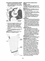
TO EMPTY GRASS CATCHER
1. Open round door of discharge chute to
move starter rope out and away from
grass catcher.
\
\
Front
OPEN
Routed
door
Starter
rope
2. Remove grass catcher with clippings
from lawn mower using both front and
rear handles.
3. Empty clippings from grass catcher
using both rear handle and strap. The
weight of the grass will open the door.
4. Snap door shut over frame before
installing grass catcher on mower.
NOTE: Do not drag the grass catcher
when emptying; it will cause unnecessary
wear.
A CAUTION: DO NOT overfill engine with
oil, or it will smoke heavily from the muffler
on startup.
1. Be sure lawnmower is level.
2. Remove oil dipstick from oil fill spout.
3. You receive a container of oil with the
unit. Slowly pour the entire container
down the oil fill spout into the engine.
4. Insert and tighten dipstick.
IMPORTANT:
* Check oil level before each use. Add oil
if needed. Fill to full line on dipstick.
. Change the oil after every 25 hours of
operation or each season. You may
need to change the oil more often
under dusty, dirty conditions. See "TO
CHANGE ENGINE OIE' in the Maintenance section of this manual.
ADD GASOLINE
* Fill fuel tank to bottom of tank filler neck.
Do not overfill. Use fresh, clean, regular
unleaded gasoline with a minimum of
87 octane. Do not mix oil with gasoline.
Purchase fuel in quantities that can be
used within 30 days to assure fuel freshness.
A CAUTION: Wipe off any spilled oil or
fuel, Do not store, spill or use gasoline
near an open flame.
CAUTION: Alcohol blended fuels
(called gasohol or using ethanol or methanol) can attract moisture which leads to
separation and formation of acids during
storage. Acidic gas can damage the fuel
system of an engine while in storage. To
avoid engine problems, the fuel system
should be emptied before storage of 30
days or longer. Empty the gas tank, start
the engine and let it run until the fuel lines
and carburetor are empty. Use fresh fuel
next season. See Storage Instructions for
additional information. Never use engine
or carburetor cleaner products in the fuel
tank or permanent damage may occur.
F_r_t
Er_gine
oil cap
BEFORE STARTING ENGINE
ADD OIL
Your lawnmower is shipped without oil in
the engine. For type and grade of oil to
use, see "ENGINE" in the Maintenance
section of this manual.
Gasoline
filler cap
10
MULCHING
TO STOP ENGINE
* To stop engine, release operator presence control bar.
TO START
MOWING TIPS
IMPORTANT: For best performance,
keep mower housing free of built-up
grass and trash. See "CLEANING" in the
Maintenance section of this manual.
ENGINE
NOTE: Due to protective coatings on the
engine, a small amount of smoke may be
present during the initial use of the product and should be considered normal.
1. To start a cold engine, push primer
three (3) times before trying to start.
Use a firm push. This step is not
usually necessary when starting an
engine which has already run for a few
minutes.
2. Hold operator presence control bar
down to the handle and pull starter
handle quickly. Do not allow starter
rope to snap back.
NOTE: In cooler weather it may be necessary to repeat priming steps. In warmer
weather over priming may cause flooding
and engine will not start. If you do flood
engine, wait a few minutes before attempting to start and do not repeat priming
steps.
* The special mulching blade will recut
the grass clippings many times and
reduce them in size so that as they fall
onto the lawn they will disperse into
the grass and not be noticed. Also, the
mulched grass will biodegrade quickly
to provide nutrients for the lawn. Always
mulch with your highest engine (blade)
speed as this will provide the best recutting action of the blades.
* Avoid cutting your lawn when it is wet.
Wet grass tends to form clumps and
interferes with the mulching action. The
best time to mow your lawn is the early
afternoon. At this time the grass has
dried, yet the newly cut area will not be
exposed to direct sunlight.
* For best results, adjust the lawn mower
cutting height so that the lawn mower
cuts off only the top one-third of the
grass blades. If the lawn is overgrown it
will be necessary to raise the height of
cut to reduce pushing effort and to keep
from overloading the engine and leaving
clumps of mulched grass. For extremely
heavy grass, reduce your width of cut
by overlapping previously cut path and
mow slowly.
MOWING TIPS
• Under certain conditions, such as very
tall grass, it may be necessary to raise
the height of cut to reduce pushing
effort and to keep from overloading the
engine and leaving clumps of grass clippings. It may also be necessary to reduce ground speed and/or run the lawn
mower over the area a second time.
• For extremely heavy cutting, reduce the
width of cut by overlapping previously
cut path and mow slowly.
• For better grass bagging and most cutting conditions, the engine speed should
be set in the FAST position.
• Pores in cloth grass catchers can become filled with dirt and dust with use
and catchers will collect less grass. To
prevent this, regularly hose catcher off
with water and let dry before using.
• Keep top of engine around starter clear
and clean of grass clippings and chaff.
This will help engine air flow and extend
engine life.
• Certain types of grass and grass
conditions may require that an area be
mulched a second time to completely
hide the clippings. When doing a second cut, mow across (perpendicular) to
the first cut path.
• Change your cutting pattern from week
to week. Mow north to south one week
then change to east to west the next
week. This will help prevent matting and
graining of the lawn.
11
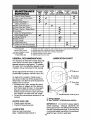
MAINTENANCE
SCHEDULE
BEFORE
EACH
USE
Check for Loose Fasteners
Clean / Inspect Grass Catcher *
CheckTires
Check Drive Wheels ***
Clean Lawn Mower ....
M Clean under Drive Cover ***
O Check Drive Belt/Pulleys
AFTER
EACH
EVERY
10
EVERY
25 HOURS
EVERY
100
BEFORE
USE HOURS
ORSEASO.
HOURS
STORAGE
,,
r,
i/
i/
i/
***
Check / Sharpen / Replace Blade
Lubrication
Clean and Recharge Ba[tery **
V
Check Engine Oil level
Change Engine Oil
Clean Air Filter
t_,2
Inspect Muffler
Replace Spark Plug
E Replace Air Filter Paper Cartridge
Empty fuel system or add Stabilizer
*
**
***
****
(if so equipped)
Electric-Start mowers
Power-Propelled mowers
Use a scraper
to clean under deck
GENERAL
1
2
3
4
5
V
- Change more often if operating under a heavy load or in high outdoortemperatures.
- Service more often if operatingin dirty or dusty conditions.
- Replace blades more often when mowing in sandy soil.
- Charge 48 hours at end of season.
- And after each 5 hours of use.
RECOMMENDATIONS
LUBRICATION
CHART
The warranty on this lawn mower does not
cover items that have been subjected to
operator abuse or negligence. To receive
full value from the warranty, operator must
maintain unit as instructed in this manual.
ine oil
Some adjustments will need to be made
periodically to properly maintain your unit.
At least once a season, check to see if
you should make any of the adiustments
described in the Service and Adiustments
section of this manual.
° At least once a year, replace the spark
plug, clean or replace air filter element
and check blade for wear. A new spark
plug and clean/new air filter element
assure proper air-fuel mixture and help
your engine run better and last longer.
° Follow the maintenance schedule in this
manual.
BEFORE
* Check
° Check
EACH USE
engine oil level.
for loose fasteners.
LU BRICATION
Keep unit well lubricated
(See "LUBRICATION
CHART').
0._ Mu]oher
door hinge pin
0._ Handle bracket rnour_tfr_g pfr_s
Spra,y lubricant
___See ENGINE in Maintenance
section.
IMPORTANT:
Do not oil or grease plastic
wheel bearings.
Viscous lubricants will
attract dust and dirt that will shorten the life of
the self-lubricating bearings. Ifyou feel they
must be lubricated, use only a dry, powdered
1 2graphite type lubricant sparingly.
Traflin
LAWN MOWER
Always observe safety rules when performing any maintenance.
TIRES
* Keep tires free of gasoline, oil, or insect
control chemicals which can harm rubber.
. Avoid stumps, stones, deep ruts, sharp
objects and other hazards that may
cause tire damage.
DRIVE WHEELS
Check rear drive wheels each time you
mow to be sure they move freely. The
wheels not turning freely means trash,
grass cuttings, etc., may be inside the
drive wheel and dust cover area and must
be cleaned out to free drive wheels.
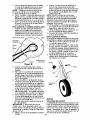
BLADE CARE
For best results, mower blade must be
kept sharp. Replace bent or damaged
blades.
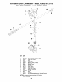
TO REMOVE
Blade adapter
Lock_asher
Blade
Blade
bolt
TO SHARPEN BLADE
NOTE: We do not recommend sharpening
the blade - but if you do, be sure the blade
is balanced.
Care should be taken to keep the blade
balanced. An unbalanced blade will
cause eventual damage to lawn mower or
engine.
• The blade can be sharpened with a file
or on a grinding wheel. Do not attempt
to sharpen while on the mower.
• To check blade balance, drive a nail into
a beam or wall. Leave about one inch of
the straight nail exposed. Place center
hole of blade over the head of the nail.
If blade is balanced, it should remain in
a horizontal position. If either end of the
blade moves downward, sharpen the
heavy end until the blade is balanced.
GRASS CATCHER
BLADE
1. Disconnect spark plug wire from spark
plug and place wire where it cannot
come in contact with spark plug.
2. Turn lawn mower on its side. Make
sure air filter and carburetor are up.
3. Use a wood block between blade and
mower housing to prevent blade from
turning when removing blade bolt.
NOTE: Protect your hands with gloves
and/or wrap blade with heavy cloth.
4. Remove blade bolt by turning counterclockwise.
5. Remove blade and attaching hardware (bolt, lock washer and hardened
washer).
TO REPLACE
Hardened
washer
o
o
BLADE
1. Position blade on the blade adapter
aligning the two (2) holes in the blade
with the raised lugs on the adapter.
2. Be sure the trailing edge of blade (opposite sharp edge) is up toward the
engine.
3. Install the blade bolt with the lock
washer and hardened washer into
blade adapter and crankshaft.
4. Use block of wood between blade and
lawn mower housing and tighten the
blade bolt, turning clockwise.
• The recommended tightening torque is
35-40 ft. Ibs.
IMPORTANT: Blade bolt is heat treated.
If bolt needs replacing, replace only with
approved bolt shown in the Repair Parts
section of this manual.
The grass catcher may be hosed with
water, but must be dry when used.
Check your grass catcher often for damage or deterioration. Through normal
use it will wear. If catcher needs replacing, replace only with approved replacement catcher shown in the Repair Parts
section of this manual. Give the lawn
mower model number when ordering.
ENGINE
LUBRICATION
Use only high quality detergent oil rated with
API service classification
SF-SJ, Select the
oil's SAE viscosity grade according
expected operating temperature.
13
to your
AIR FILTER
NOTE: Although multi-viscosity oils
(5W30, 10W30 etc.) improve starting
in cold weather, they will result in
increased oil consumption when used
above 32°F. Check your engine oil level
more frequently to avoid possible engine
damage from running low on oil.
Change the oil after every 25 hours of operation or at least once a year if the lawn mower
is not used for 25 hours in one year.
Check the crankcase oil level before
starting the engine and after each five (5)
hours of continuous use. Tighten oil plug
securely each time you check the oil level.
Your engine will not run properly and
may be damaged by using a dirty air
filter. Replace the air filter cartridge every
100 hours of operation or every season,
whichever occurs first. Service air cleaner
more often under dusty conditions.
TO CLEAN AIR FILTER
1. Loosen screw and tilt cover to remove.
2. Carefully remove cartridge.
3. Clean by gently tapping on a flat surface. If very dirty, replace cartridge.
_I,CAUTION: Petroleum solvents, such
as kerosene, are not to be used to clean
cartridge. They may cause deterioration
of the cartridge. Do not oil cartridge. Do
not use pressurized air to clean or dry
cartridge.
4. Install cartridge, then replace cover
making sure the tabs are aligned with
the slots in the back plate. Fasten
screw securely.
TO CHANGE ENGINE OIL
NOTE: Before tipping lawn mower to drain
oil, empty fuel tank by running engine until
fuel tank is empty,
1. Disconnect spark plug wire from spark
plug and place wire where it cannot
come in contact with plug,
2. Remove engine oil cap; lay aside on a
clean surface,
3. Tip lawn mower on its side as shown
and drain oil into a suitable container.
Rock lawn mower back and forth to remove any oil trapped inside of engine.
Back
Cover
Cover
tabs
MUFFLER
Inspect and replace corroded muffler as it
could create a fire hazard and/or damage.
SPARK PLUG
Replace spark plug at the beginning of
each mowing season or after every 100
hours of operation, whichever occurs
first. Spark plug type and gap setting
are shown in the "PRODUCT SPECIFICATIONS" section of this manual.
4. Wipe off any spilled oil from lawn
mower or side of engine.
5. Slowly pour oil down the oil fill spout,
stopping every few ounces to check the
oil level with the dipstick.
6. Stop adding oil when you reach the
FULL mark on the dipstick. Wait a
minute to allow oil to settle.
7. Continue adding small amounts of oil,
rechecking the dipstick until oil level
settles at FULL. DO NOT overfill, or
engine will smoke heavily from the muffler on startup.
8. Always be sure to retighten oil dipstick
before starting engine.
9. Reconnect spark plug wire to spark
plug.
CLEANING
IMPORTANT: For best performance,
keep mower housing free of built-grass
and trash. Clean the underside of your
mower after each use.
/I, CAUTION: Disconnect spark plug wire
from spark plug and place wire where it
cannot come in contact with plug.
* Clean the underside of your lawn
mower by scraping to remove build-up
of grass and trash.
14
° Clean engine often to keep trash from
accumulating. A clogged engine runs
hotter and shortens engine life.
° Keep finished surfaces and wheels free
of all gasoline, oil, etc.
° We do not recommend using a garden
hose to clean lawn mower unless the
electrical system, muffler, air filter and
carburetor are covered to keep water
out. Water in engine can result in shortened engine life.
CLEAN UNDER DRIVE COVER
Clean under drive cover at least twice a
season. Scrape underside of cover with
putty knife or similar tool to remove any
build-up of trash or grass on underside of
drive cover.
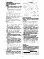
_i, WARNING: To avoid serious injury,before
performing any service and adjustments:
1. Release control bar and stop engine.
2. Make sure the blade and all moving
parts have completely stopped.
3. Disconnect spark plug wire from spark
plug and place wire where it cannot
come in contact with plug.
3. Remove drive cable from anchor, then
detach the drive cable spring from the
idler arm assembly (See Figure B).
Idler arm
assembly_
Drive cable anchor
Drive belt
LAWN MOWER
TO ADJUST CUTTING HEIGHT
See '%0 ADJUST CUTTING HEIGHT" in
the Operation section of this manual.
REAR DEFLECTOR
The rear deflector, attached between the
rear wheels of your mower, is provided to
minimize the possibility that objects will be
thrown out of the rear of the mower into
the operator mowing position. If deflector
becomes damaged, it should be replaced.
TO REMOVE DRIVE BELT
1. Disconnect spark plug wire from spark
plug and place wire where it cannot
come in contact with plug,
2. Remove screws retaining drive cover
and remove drive cover from lawn
mower housing (See Figure A).
pulley
\ Housing
\
hole
Belt keeper
Figure B
4. Pivot idler arm assembly to slacken
drive belt, then remove drive belt from
drive pulley, belt keepers and idler arm.
5. Turn lawn mower on its side. Make
sure air filter and carburetor are up.
6. Remove screw securing debris shield.
Note that the debris shield has a tab
which fits into a gap in the housing
(See Figure C).
Crar_kshaft
Tab
Housing
hole
Blade
adapter
(pulley
er_d)
Lawn
mower"
housfr_g
Drive
COVer
Blade
bolt
Lc.ck-washer
Trailing edge
Figure A
15
Figure
C
7. Use a wood block between blade and
mower housing to prevent blade from
turning when removing blade bolt.
NOTE: Protect your hands with gloves
and/or wrap blade with heavy cloth.
8. Remove blade bolt.
9. Remove blade, attaching hardware
(bolt, lock washer and hardened washer), blade adapter and debris shield as
one assembly.
10. Remove drive belt from blade adapter
and debris shield; discard old belt.
TO REPLACE DRIVE BELT
Place new drive belt in the belt retainer
of the debris shield. Be sure to route
belt between belt keepers and through
slot (See Figure D).
.
Tab
Belt
Drive
belt
Be sure belt is inside of belt keepers
(See Figure B).
NOTE" Pulling on the drive belt (to install
it on the drive pulley) will cause the other
end of the belt to free itself from the debris
shield retainer and properly seat itself in
groove of pulley end of the blade adapter.
10. Reattach drive cable spring to the idler
arm assembly, then reattach drive
cable to anchor.
11. Reattach drive cover with screws previously removed.
12.Connect spark plug wire to spark plug.
TO ADJUST HANDLE
The handle on your lawn mower has
multiple height positions - adjust to height
that suits you.
1. Remove knob and carriage bolt on left
side of the lower handle.
2. While holding handle assembly, remove knob and carriage bolt from right
side. Align hole in handle with desired
hole in handle bracket, then reassemble bolt and knob and tighten securely.
3. Align left side of handle with same positioning hole as right side and secure
with bolt and knob.
Bolt
Slot
Debris
shield
Figure D
2. Route the other end of the new drive
belt through hole in housing.
3. Reattach debris shield to housing with
screw previously removed. Be sure tab
of debris shield is in gap of housing.
4. Position blade on the blade adapter
aligning the two (2) holes in the blade
with the raised lugs on the adapter.
5. Be sure the trailing edge of blade (opposite sharp edge) is up toward the
engine (See Figure C).
6. Install the blade bolt with the lock
washer and hardened washer into
blade adapter and crankshaft.
7. Use block of wood between blade and
lawn mower housing and tighten the
blade bolt, turning clockwise.
• The recommended tightening torque is
35-40 ft. Ibs.
IMPORTANT: Blade bolt is heat treated.
If bolt needs replacing, replace only with
approved bolt shown in the Repair Parts
section of this manual.
8. Return mower to upright position.
9. Install new drive belt into idler arm
assembly, then around the drive pulley. 16
Handle
ENGINE
ENGINE SPEED
Your engine speed has been factory set.
Do not attempt to increase engine speed
or it may result in personal injury. If you
believe that engine is running too fast or
too slow, take your mower to a Sears or
other qualified service center for repair
and adjustment.
CARBURETOR
for proper engine speed. Overspeeding
the engine above the factory high speed
setting can be dangerous. If you think
the engine-governed high speed needs
adjusting, contact a Sears or other
qualified service center, which has proper
equipment and experience to make any
necessary adjustments.
Your carburetor is not adjustable.
If your
engine does not operate properly due to suspected carburetor problems, take your lawn
mower to a Sears or other qualified service
center for repair and/or adjustment.
IMPORTANT: Never tamper with the
engine governor, which is factory set
Immediately prepare your lawn mower for
storage at the end of the season or if the
unit will not be used for 30 days or more.
IMPORTANT: When folding the handle for
storage or transportation, be sure to fold it
as shown or you may damage the control
cables.
LAWN MOWER
When lawn mower is to be stored for a
period of time, clean it thoroughly, remove
all dirt, grease, leaves, etc. Store in a
clean, dry area.
1. Clean entire lawn mower (See
"CLEANING" in the Maintenance section of this manual).
2. Lubricate as shown in the Maintenance
section of this manual.
3. Be sure that all nuts, bolts, screws, and
pins are securely fastened. Inspect
moving parts for damage, breakage
and wear. Replace if necessary.
4. Touch up all rusted or chipped paint
surfaces. Be sure to sand surface
lightly before painting.
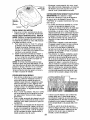
HANDLE
You can fold your lawn mower handle for
storage.
NOTE: The upper handle has an "antifold" bracket located on the left side of the
handle. This bracket prevents the upper
handle from folding forward, which helps
protect control cable(s) from damage.
1. Loosen the two (2) handle knobs on
sides of the upper handle and allow
handle to fold down to the rear.
2. Remove the two (2) handle knobs and
carriage bolts on sides of the lower
handle and pivot entire handle assembly forward and allow it to rest on
mower.
3. Reinstall knobs and carriage bolts to
lower handle or handle brackets for
safe keeping.
• When setting up your handle from the
storage position, you must manually
lock lower handle into mowing position.
Operator presence
control bar
Lower
Mowing
positio_
3olt
K_ob\\
Handle'
bracket
17
ENGINE OIL
Drain oil (with engine warm) and replace
with clean engine oil. (See "ENGINE" in
the Maintenance section of this manual).
CYLINDER
ENGINE
FUEL
SYSTEM
IMPORTANT: It is important to prevent
gum deposits from forming in essential
fuel system parts such as carburetor, fuel
filter, fuel hose, or tank during storage.
Also, alcohol blended fuels (called gasohol
or using ethanol or methanol) can attract
moisture which leads to separation and
formation of acids during storage. Acidic
gas can damage the fuel system of an
engine while in storage.
* Empty the fuel tank by starting the engine and letting it run until the fuel lines
and carburetor are empty.
* Never use engine or carburetor cleaner
products in the fuel tank or permanent
damage may occur.
* Use fresh fuel next season.
NOTE: Fuel stabilizer is an acceptable
alternative in minimizing the formation of
fuel gum deposits during storage. Add
stabilizer to gasoline in fuel tank or storage container. Always follow the mix ratio
found on stabilizer container. Run engine
at least 10 minutes after adding stabilizer
to allow the stabilizer to reach the carburetor. Do not empty the gas tank and
carburetor if using fuel stabilizer.
1. Remove spark plug.
2. Pour one ounce (29 ml) of oil through
spark plug hole into cylinder.
3. Pull starter handle slowly a few times
to distribute oil.
4. Replace with new spark plug.
OTHER
* Do not store gasoline from one season
to another.
* Replace your gasoline can if your can
starts to rust. Rust and/or dirt in your
gasoline will cause problems.
* If possible, store your unit indoors and
cover it to protect it from dust and dirt.
* Cover your unit with a suitable protective cover that does not retain moisture.
Do not use plastic. Plastic cannot
breathe, which allows condensation to
form and will cause your unit to rust.
IMPORTANT: Never cover mower while
engine and exhaust areas are still warm.
_I,CAUTION: Never store the lawn mower
with gasoline in the tank inside a building
where fumes may reach an open flame
or spark. Allow the engine to cool before
storing in any enclosure.
TROUBLESHOOTING
- See appropriate
to a Sears Service Center,
PROBLEM
Does not start
section in manual unless directed
CAUSE
CORRECTION
1. Dirty air filter.
2. Out of fuel.
3. Stale fuel.
Clean/replace air filter.
2. Fill fuel tank.
3. Empty fuel tank and refill tank
with fresh, clean gasoline.
4. Empty fuel tank and refill tank
with fresh, clean gasoline.
5. Connect wire to plug.
.
4.
Water in fuel.
5.
Spark plug wire is
disconnected.
6.
7.
Bad spark plug.
Loose blade or broken
blade adapter.
8. Control bar in released
position.
9. Control bar defective.
10. Fuel valve lever (if so
equipped) in OFF position.
11. Weak battery (if equipped).
12, Disconnected battery
connector (if equipped).
18
6. Replace spark plug.
7. Tighten blade bolt or
replace blade adapter.
8. Depress control bar to
handle.
9. Replace control bar.
10. Turn fuel valve lever
to the ON position.
11. Charge battery.
12. Connect battery to engine.
TROUBLESHOOTING
to a Sears Service
- See appropriate
PROBLEM
Loss of power
Poor cut -
section in manual unless directed
Center,
CAUSE
CORRECTION
1, Rear of mower housing or
blade dragging in grass.
2. Cutting too much grass.
3. Dirtyair filter.
4. Buildup of grass, leaves,
and trash under mower.
5. Too much oil in engine.
6. Walking speed too fast.
1. Worn, bent or loose blade.
uneven
2. Wheel heights uneven.
3. Buildup of grass, leaves
and trash under mower.
Excessive
vibration
1. Worn, bent or loose blade.
2. Bent engine crankshaft.
Starter rope
hard to pull
1. Engine flywheel brake is on
when control bar is released.
2. Bent engine crankshaft.
3. Blade adapter broken.
4. Blade dragging in grass.
•
Raise cutting height.
2, Raise cutting height.
3, Clean/replace air filter.
4, Clean underside of mower
housing.
Check oil level.
6, Cut at slower walking speed.
•
1. Replace blade. Tighten
blade bolt.
2. Set all wheels at same
height.
3. Clean underside of
mower housing.
1. Replace blade. Tighten
blade bolt.
2. Contact a Sears or other
qualified service center.
1. Depress control bar to
upper handle before
pulling the starter rope.
2. Contact a Sears or other
qualified service center.
3. Replace blade adapter.
4. Move lawn mower to cut
grass or to hard surface.
Grass catcher
not filling
(If so equipped)
1. Cutting height too low.
2. Lift on blade worn off.
3. Catcher not venting air.
Raise cutting height.
Replace blade.
3. Clean grass catcher.
Ha_ to push
1. Grass is too high or wheel
height is too low.
2. Rear of mower housing or
blade dragging in grass.
3. Grass catcher too full.
4. Handle height position not
right for you.
1. Raise cutting height•
Loss of drive
or slowing of
drive speed
1.
2.
3.
4.
Belt wear.
Belt off of pulley.
Drive cable worn or broken.
"Loose" drive control system.
19
2. Raise rear of mower housing
one (1) setting higher.
3. Empty grass catcher.
4. Adjust handle height to suit.
.•
3.
4.
Check/replace
Check/reinstall drive
drive belt.
belt.
Replace drive cable.
Adjust drive control.
Ga_ntia .........................................................
20
Reglas de Segurldad ................................ 20-22
Montaje / Pre-Operacibr_ .......................... 23-24
Operacibr_ .................................................
25-29
Mantenimierlo ..........................................
30-33
Programa de Mantenimierlo ......................... 31
Especificacior_es del Producto ....................... 22
Servicio y Adjustes ................................... 33-35
Almacenamler_to .......................................
35-36
Iderllflcacl6n de problemas ...................... 36-37
Partes de repuesto .................................. 38-47
Servlclo Sears .................................. Contratapa
GARANT[A LIMITADA DE DOS AhlOS PARA LA SEGADORA A MOTOR CRAFTSMAN
Pot dos (2) aSos, a partfr de la fecha de compra, cuar_do esta Segadora Craftsman se mantenga,
lubfique y afine seg_n las fr_struccior_es para la operacf6n y el manter_fmierlo en el mar_ual del
dueSo, Sears reparar_ gratfs todo defecto er_ el material y la mano de obra.
Si la Segadora Craftsman se usa para fines comerciales o de arrier_do, esta garantia s61o se aplica
pot r_oventa (90) dias a partfr de la fecha de compra.
Esta Gararlia
no cubrs:
° Articu]os que se desgastar_ durante el uso normal tales como las cuchil]as segadoras rotatorias,
los adaptadorss de la cuchf]la, las oorreas, los filtros de airs y las bujias.
° Reparacior_es r_ecesafias debfdo al abuso o a la r_eglfger_cfadel operador, fncluyer_dose a los
cig_eSales doblados y a la falta de mantenimiento del equipo seg_n las fr_struccior_es que se
ir_cluyer_er_ el manual del dueSo.
El serviclo de garantia esta disponible al devolver la segadora a motor Craftsman al Cerlro de
Servicfo Sears mas cercano er_ los Estados Urtdos. Esta garar_t°a se aplica solamente mierlras
producto este en uso en los Estados Ur_fdos.
el
Esta Gararlia le otorga derschos legales especfffcos, y puede que tambi_n tenga otros derschos
que var°ar_ de estado a estado.
Sears, Roebuck and Co., D/817WA, Hoffman Estates, IL 60179
USA
IMPORTANTE: Esta maquina cortadaora es capaz de amputar las manos y los manos y los pies y
de lar_zar obietos. Sf no se observan las ir_struccior_es de seguridad sfguientes se pueden producir
lesiones graves o la muerte.
4,Busque este sfmbolo que se_ala las precauclones de segurfdad de fmportancfa. Quiere
declr - i iiATENCION!!! i iiESTE ALERTO!!!
SU SEGURIDAD ESTA COMPROMETIDA.
_,DVERTENCIA:
Siempre desoonecte el
alambrs de la bujfa y pbr_galo dor_de r_opueda
erlrar er_ cor_tacto con la bujfa, para evftar el
arrar_que pot accidente, durarle la preparacibr%
el transporte, el ajuste o cuando se hacen
reparacfones.
_ADVERTENCIA:
Los bornes, terminales y
accesorlos relativos de la bateria corllenen
plomo o compuestos de plomo, productos
qufmicos conocidos er_ el Estado de Califomfa
como causa de c_ncer y defectos al nacfmfento
u otros daSos reproductlvos. Lavar las manos
despu_s de manipularlos.
/[I, PRECAUCI()N: El tubo de escape del motor,
algur_os de sus constituyerles y algur_os compor_entes del veh°culo contiener_ o desprsr_der_
productos qu°mfcos conocfdos er_ el Estado de
Califomfa como causa de c_ncer y defectos al
nacimiento u otros da_os reproductivos.
_PRECAUCI()N:
El sHenciador y otras
pfezas del motor Ilegan a sre extrsmadamente
calientes durante la operacibr_ y sfguen sier_do
calientes despu_s de que el motor haya parado.
Para evftar quemaduras severas, permar_ezca
lejos de estas _treas.
2O
I. OPERACION
° Antesdeempezar, debefami]iarizarsecompletamente con los controles y el uso correcto de
la maquir_a. Para esto, debe leer y comprer_der
todas las fnstrucciones que apa_cen er_la maqufna y er_ los manuales de operaoi6r_.
° No por_ga las matzos o los pies cerca o
debaio de las partes rotatorias. Mar_t_r_gase
siempre lejos de la abertura de la desoarga.
• Permfta que solamente las personas responsables que est_n familiarfzadas con las
ir_struocfonesoperen la m_quina.
° Despeie el _rea de obietos tales oomo piedras, iuguetes, alambres, huesos, palos, etc.
que pueder_ set recogidos y lar_zados pot las
ouchf]las.
° AsegO_se que el _rea r_ose haller_ personas, ar_tes de segar. Pare la m_tqufna si
alguier_ er_tra er_ el _a.
° No ope_ la maquir_a sin zapatos o con sar_dalias abiertas. Pbngase siempre zapatos s61idos.
° No tf_ de la segadora haoia atr_ts a menos
que sea absolutamente necesario. Mire
siempre haofa abajo y haoia detrlis antes y
mfentras que se mueve hacfa atrlis.
° No opere la segadora sin los _speotivos
resguardos, las placas, el reoogedor de
o_sped u otros adftamentos dise ados para
su protecci6n y seguridad.
• Refi_rase alas fnstruccfones del fabricar_te
para el fur_cionamfento e ir_stalaoibr_de
accesorios. Use 0r_foamente accesorfos
aprobados pot el fabricar_te.
° Deter_ga la ouohf]]a o las ouohillas ouando cruce
pot calzadas, oalles o earnings de grava.
° Parar el motor cada vez que se abar_dona el
aparato, antes de limpiar la segadora o de
remover residuos del tubo.
• Apagar el motor y esperar hasta que las
ouchf]las est_r_ completamente paradas
antes de remover el receptor de hferba.
• Segar solamente con luz del d°a o cor_ urea
buena luz artificial.
• No opere la m_quir_a baio la irffluer_oiadel
alcohol o de las drogas.
• Nut, ca opere la maquina cuar_do la hierba
est_ mojada. Aseg0rese sfempre de terser
buena traccibr_ er_ sus pies; mantenga el
rear,go firmemer_te y oamine; r_ur_cacorra.
• Desoor_ectar el mecanismo de propulsl6n
aut6r_oma o el embrague de trar_smfsf6nen
las segadoras que 1otier_en antes de por_er
en marcha el motor.
= Si el equipo empezara a vibrar de una
rear,era anormal, pare el motor y revise de
ir_medfato para averfguar la causa. Generalmer_te la vibracf6n suele indfcar que exfste
algur_a averia.
• Sfemp_ use gafas de segurfdad o ar_teojos con
proteccfbr_ lateral ouar_do opere la segadora.
II. OPERACION
SOBRE LAS CUESTAS
Los accfder_tes ocurren cor_m_s frecuenofa en
las cuestas. Estos accfder_tes ccurrer_ debfdo a
resbaladas o caidas, las cuales pueden resultar
er_ graves lesior_es. Operar la recortadora er_
cuestas requiere mayor oonoer_traoibr_. Sf se
sfente inseguro en urea ouesta, no la recorte.
HACER:
• Puede recortar a tray,s de la superficie de
la cuesta, nunca haoia arriba y hacia abajo.
Prcceda con extrema precauci6r_ cuando
cambie de dfreccibr_ er_ las cuestas.
° Renueva todos los objetos extraSos, tales
como gufiarros, ramas, etc.
° Debe prestar ater_cf6n a hoyos, bathes o
protuberancfas. Recuerde que la hierba alta
puede escor_der obst_cu]os.
NO HACER:
° No recorte ceroa de per_dier_tes, zar_jas o
terraplenes. El operador puede perder la
traccibr_ er_ los pies o el equilfbrio.
° No recorte cuestas demasiado inclfnadas.
° No recorte en hferba mojada. La reduccf6n
er_ la tracci6r_ de la pisada puede causar
resbalones.
III, Nli_lO$
Se pueder_ producfr accidentes tr_tgicos si el
operador r_opresta ater_ci6r_ a la preser_cfa
de los nffios. A mer_udo, los r_ffiosse sfenten
atraidos pot la m_tquir_a y pot la actfvidad de
la sfega. Nunca supor_ga que los r_iiiosvan a
permar_ecer er_ el raising lugar donde los vfo
pot dltima vez.
• Mantenga a los nifios aleiados del _rea de
la siega y baio el ouidado estrfcto de otra
persor_a adulta respor_sable.
• Est_ alerta y apague la m_tquir_a si hay niSos
que er_trar_al _a.
• Ar_tes y ouando este retrccedfendo, mire
hacfa atr_ts y haoia abajo para veriffcar sf hay
niSos pequeSos.
° Nunca permfta que los r_fiiosoperer_ la m_tquir_a.
° Ter_ga un cuidado extra cuar_do se aoerque
a esquir_as donde no hay visfbilidad, a los
arbustos, _rboles u otros obietos que pueden
fnterferfr con su lir_ea de visibr_.
21
IV. SERVICIO
° Ter_ga cufdado extra al mar_eiar la gasolir_a y
los demos combustibles. Son inflamables y
los oases sor_ explosivos.
- Use solamente ur_ envase aprobado.
- Nut, ca remueva la tapa del depbsito de
gasolfna o agregue combustible cor_ el motor funcionando. Permfta que el motor se
enfr°e antes de volver a porte combustible.
No fume.
- Nut,ca vuelva a porter combustible en la
m_tquina en recintos cerrados.
- Nut, ca almaoer_e la m_quina o el envase
del combustible dentro de alg0r_ lugar en
donde haya urea llama expuesta, tal oomo
la del oaler_tador de agua.
Nunoa haga funcior_ar urea m_quir_a dentro
de ur__trea cerrada.
, Nunoa haga aiustes o reparacfones mier_tras
el motor est_ en marcha. Desoonecte el
cable de la buiia, y mar_t_r_galo a cierta
distar_cfa de _sta para prever_ir ur_ arrar_que
accidental.
° Mantenga las tuercas y los pernos, especfalmente los perr_os del accesorfo de la
cuohilla, apretados y mar_ter_ga el equipo en
buenas oondiofor_es.
° Nut,ca manipu]edeformair_debida
los
dfsposftfvos
desegurfdad.
Controleregularmeritssufur_cionamfento
correcto.
° Mar_ter_ga
la m_quinalibredehferba,hojas
° Los compor_entes del receptor de la hferba
van sujetos a desgaste, da_os y deterioro,
que pueden exporter las partes er_ movfmier_to o permitfr que objetos sean dfsparados. Controlar frecuer_temente y cuando sea
necesario sustftuir cor_ partes acor_seiadas
por el fabrfcante.
° Las cuchil]as de la segadora est_tr_aff]adas y
pueder_ cortar. Cubrir las hoias o Ilevar guantes,
y utflizar precaucfor_es especfales cuando se
efect0a mar_ter_fmier_tosobre las mfsmas.
• No oambie el ajuste del regulador del motor
ni exoeda su velocfdad.
u otras acumulaciones de desperdfcio.
Lfmpie los derrames de acefte o combustfble.
Permfta que la m_quir_a se enfr°e antes de
almacenarla.
• Pare e fr_speccior_e el equipo si le pega a un
objeto. Rep_ralo, sf es r_ecesarfo, antes de
hacerlo arrancar.
• Er_ r_ir_g_r_
caso hay que regular la altura de
las ruedas mfentras el motor ester en marcha.
Nfimero de Serie:
Fecha de Compra:
Capacidad y Tipo de Gasolina:
1,6 Cuartos (Regular sin Plomo)
Tipo de Aceite (API-SF-SJ):
SAE 30 (Sobre 32°F); SAE 5W-30 (Debajo 32°F)
Capacidad de Aceite:
20 Onzas
Bujfa (Abertura: .030")
Torsi6n del Perno de la Cuchilla:
Champion RJ19LM o J19LM
35-40 ft. Ibs.
El r_mero del nodelo y el de serie se er_cuer_trar_
en la calcomania adjur_taa la parts trasera
de la caia de la segadora. Debe registrar tanto el r_mero de serie come la fecha de compra y
mar_ter_galosen un lugar seguro para refer_ciaer_el futuro.
Acuerdos de Protection
Congratulaciones pot su buena compra. Su
nuevo producto Craftsmar_® est_ dise_ado
y fabrfcado para funcfonar de modo fiable pot
muchos a_os. Pero como todos los productos,
puede necesftar alguna reparaci6r_ de tar_to
er_ tar_to. En este caso terser ur_ Acuerdo de
Proteccf6n para la Reparaci6n puede hacerles
ahorrar dinero y fastidios.
para la Reparation
° Ayuda rdpida pot tel_fono - soporte telef6r_fco por parts de un t_cnfco Sears sobra
productos que requierar_ ur_ arreglo en casa,
y adem_ts urea programaci6r_ sobre los a
reglos m_ts convenfer_tes.
Cuando se ha comprado el Acuerdo, basta cor_
una l]amada telef6nfca para programar el servicio. Puede llamar cuando quiera, d°a y noche o
ffjar en lir_ea una cfta para obter_er el servicfo.
Sears tier_e m_ts de 12.000 especialistas
profesior_ales en la reparacibr_, que tier_er_
acceso a m_ts de 4.5 mfllor_es de partes y
accesorfos de calidad. Este es el tipo de
profesior_alidad con que puede contar para
ayudar a alargar la vfda del producto que acaba
de comprar, por muchos a_os. iCompre boy su
Acuerdo de Protecci6r_ para la Reparaci6r_!
Se aplican algunas limitaciones y exolusiones. Para conocer los precios y tener
m_s informacibn, Ilarne al 1-800-827-6655.
Compre ahora un Acuerdo de Proteeci6n para
la Fteparaci6n y prot_gese de molestias y gastos inesperados.
Un Aouerdo ir_oluye los puntos sigufentes:
• Servicio experto de nuestros 12.000 especialistas profesfor_ales er_ la reparacf6r_.
• Servioio ilimitado sin cargo alguno para
las partes y la mano de obra sobrs todas las
reparacior_es garantfzadas.
• Sustituci6n
dsl producto si su producto
garar_tfzado no puede ser arraglado.
• Descuento del 10% sobre el precio corriente del servicio y de las partes relativas al
servicio r_ocubiertas por el acuerdo; tambi_r_
el 10% metros sobre el pracio corrfente de
un cor_trol de manter_fmier_to prever_tfvo.
Servicio de Instalacion Sears
Para la instalaciSn profesional Seam de
aparatos de casa, puertas de garaje,
calentadores de agua y otros fmportantes
art°culos para la casa, en U.S.A. llamar a
1-800-4-MY-HOME@.
22
Estos accesorios estabar_ disponibles cuando se produjo la segadora. No son facilitados junto al
cortacesped. Tarnbi_n est_n dfspor_ibles en la mayor°a de las tfendas de Sears y en los cenVos de
servfcfo. Algunos de estos accesorios tal vez r_ose aplfquen a su segadora.
RENDIMIENTO
DE LA SEGADORA
DE RECORTES
PAPA SEGADORAS
CON DESCARGA
DESVIADOR
TRASERA
__
\\
\
\\\
_
, --
RECOREDOR
PAPA
\\
RECOREDOR
PARA
CON DESCARGA
TRASERA
SEGADORAS
MANTENIMIENTO
_
_
CON DESCARGA
LATERAL
SEGADORAS
/
DE LA SEGADORA
SILENCIADORES
CORREAS
ESTABILIZADORES
CUCHILLAS
FILTROS DE AIRE
ADAFI'A_RES
DE CUCHILLA
RUEDAS
BUJ[AS
ACEI_
DEL MOTOR
PARA REMOVER
LA SEGADORA
DE
LA CAJA DE CARTON
1. Remueva las partes sueltas que se ir_oluyer_
co_ la segadora.
2. Corte las dos esquir_as de los extremos
de la oaja de cartbn y tfenda el parcel del
exVemo piano.
3. Remueva todo el materfal de empaque, exoepto la cuSa er_tre el rear, go superior y _1
inferfor, y la cuSa que sujeta la barra de los
cor_trol que exige la presencfa del operador
jur_to oor_ el rear,go superfor.
4. Haga rodar la segadora hacia afuera de la
oaja de oart6n y r'evisela cuidadosamer_te
para verifioar si todav°a quedar_ partes
sueltas adfcionales.
Lea estas insVuccTones y este manual oompletamer_te antes de tratar de mor_tar u operar su
segadora r_ueva.
IMPORTANTE: Este cortao_sped vier_e SIN
ACEITE O GASOLINA er_ el motor.
Su segadora nueva ha sfdo mor_tada en la
f_brica oor_ la exoepofbr_ de aquel]as partes que
se dejaror_ sfr_ rnontar pot razones de env°o.
Todas las partes oorno las tuercas, las arar_delas, los pernos, etc., que sor_ necesarias para
completar el rnontaie hart sido colocadas er_ la
bolsa de partes. Para asegurarse que su segadora funcione er_ forrna segura y adecuada,
todas las partes y los art°culos de ferreteria que
se mor_ter_tfenen que set apretados segurarnente. Use las herramfentas correctas, corno
sea neoesario, para asegurar que se aprfeter_
adecuadamer_te.
23
PARA MONTAR EL RECOGEDOR DE
CESPED
1. Deslfzar el saeo de la hierba sobre el
armaz6n. Asegurarse de que el mango
trasero est_ arriba (el mismo lade que el
mango delantero) y la abrazadera abajo.
2. Deslfce los sujetadores de vfnflo sobre el
bastfdor.
AVlSO: Si los sujetadores de vfnilo est_tn muy
duros, m_talos en agua ealiente per algunos
minutes. Sf se moja la bolsa, d_jela que se
seque antes de usarla.
3. Cerrar la puerta del depbsito de hferba.
AMISO: Cuando est_ completamente eerrada,
la puerta se cerrar_ con un dfsparo sobre el
armazbn y los elementos de fiiaefbn en vinflo.
COMO PREPARAR
SU SEGADORA
PARA DESDOBLAR EL MANGO
IMPORTANTE: Desplfegue el mango con
touche cuidado para no pellizear o dariar los
cables de control.
1. Levante la secci6n del mango fnferior hasta
la posicibn de operacf6n y alinee el aguiero
en _ste con uno de los agujeros para determfnar la altura en el puntal del mango.
2. Inserte el pemo del mango a tray,s de _ste
y del puntal y aseg0relo con la manflla.
3. Repfta el procedimfento para el lade
opuesto del mango.
4. Levante la secci6n del mango superfor
hasta la posfci6n de operacibn, remueva la
curia protectora y apriete las manfllas del
mango en forma segura.
5. Remueva el materfal de empaque de alrededor de la barra de control.
El mango de la segadora puede aiustarse
seg0n le acomode para segar. Refi_rase a
"AJUSTE DEL MANGO" en la seccibn de
Servicfo y Ajustes de este manual.
_arra de control ¢
/,
/_
Mango
posterior
/
Correa
la presenoia del operador
Mango superior
Mango Inferior
LEVANYAR
Posici6n
para segar
El bastidor
del
_
:_,
\
/
Sujetadores
de vinilo
Manilla
f.
•
S
/
\
\
\
/
\
/
Soporte
de mango
PARA INSTALAR LOS ACCESORIOS
Su segadora fue envfada lista para usarse
come una aeolchadora de eapa vegetal. Para
convertirla de mode que pueda ensaear o
desearga, refi_rase a "PAFtA CONVEFtlR LA
SEGADORA" en la seccibn de Operacibn de
este manual.
24
FAMILIARICESECON SU SEGADORA
LEAESTEMANUAL DEL DUENOY LAS REGLAS
DE SEGURIDAD ANTES DE OPARAR SU
SEGADORA. Compare las ilustracfones con su segadora para famf]iarfzarse con la ubfoaci6n de
los diversos ¢ontroles y ajustes. Guarde este manual para referencfa en el futuro.
Estos simbolos pueden apareser sobre su segadora o en la literatura proporoionada
producto. Aprenda y comprenda sus significados.
A'n'ENCI6N O
MOTOR
MOTOR
ADVERTENCIA ENCENDIDO APAGADO
RAPIDO
LENTO
ESTRANGU
LACION
con el
COMACEITE
PELIGRO, GUARDE LAS
BUSTIBLE
MANOS Y LOS PIES LEJO8
Barra de control que exige la
presencia del operador
Palanca de control de la impulsfbn
Cordbn
mango
Tapa del deposito de aciete
del motor con varf]la
indfcadora de nfvel
Recogedor
Silenciador
Mango del
_ustador
de un duel
punto
Tapa del deposito
de la gasolina
Filtro de airs
Puerta de la acolchadora
Cebador
IMPORTANTE:
CUMPLE CON
I_as segadoras
los est_ndarss
Product Safety
Caja
Este cortao_sped viene SIN ACEITE O GASOLINA en motor.
LOS REQUISITOS DE SEGURIDAD DE LA CPSC
a motor, que se oonducen desde la parte de atr_is, rotatorias, Sears, oumplen con
de segurfdad del Amerfcan National Standards Institute y de la U.S. Consumer
Commfssfon. 1_8ouohflla gfra cuando el motor est_ funoionando.
Cebador - bombea combustfble adicional
desde el carburador al cilfndro para uso ouando
se necesfta hater arrancar un motor fr°o.
Palanoa de control de la impulsion - se usa
para enganchar la segadora para movfmfento
hacia adelante fmpu]sada a motor.
Mango del ajustador de un dual punto-se usa
para ajustar la altura de corte de la segadora.
Barra de control que exige la presencia del
operador - tiene que sujetarse abajo, junto
con el mango, para hacer arrancar el motor.
Su_ltela para parar el motor.
Cordbn arraneador - se usa para hacer arrancar el motor.
Puerta de la acolchadora - permfte la conversi6n para la operacf6n de descarga o ensacado.
25
La operacibr_ de cualquier
segadora puede hacer que
salten obietos extrafios dentro de
sus gigs, 1oque puede produclr
daSos graves er_ _stos. Siempre
use ar_teojos de segurfdad o proteccfbn para
los ojos mier_tras opere su segadora o ouar_do
haga aiustes o reparacfones. Reoomer_damos
gafas o una mascara de seguridad de visfbn
amplfa de seguridad usada sobre las gafas.
COMO USAR SU SEGADORA
VELOCIDAD DEL MOTOR
La velocldad del motor se establecl6 er_ la f_brioa para ur_ rendimfento 6ptfmo. La velooidad
no se puede ajustar.
dI_NTROL DE ZONA DEL MOTOR
PRECAUCION: Las regulaoior_es federales
exiger_ que se fr_stale un control para el motor
er_esta segadora para reducfr a ur_ mir_fmo el
riesgo de lesfor_arse debfdo al cor_tacto con la
cucDilla. Pot r_ir_g0r_
motfvo trate de elfminar
la funci6r_ del control del operador. La cuchilla
gira cuar_do el motor est_ fur_cfonar_do.
° Su segadora vier_e equipada con una barra
de oontroles que exigen la preser_cfa del
operador, 1oque requiere que el operador
est_ detr_ts del mango de la segadora para
hacerla arranoar y operarla.
CONTROL DE LA IMPULSK)N
• 1_8autopropulsibr_ se ¢or_trola mar_tenier_do
la palar_ca de mando operador presente
abajo haoia el mango y tirar_do la palar_ca de
accionamfento atr_is haoia el mango. Cuar_to
m_ts lejos se tira la palar_ca hacfa el rear,go,
m_ts r_tpfda ir_tla unidad.
• El movfmfer_to hacfa adelar_te se detfene
ouando sea la palanoa de mando operador
presente o la palanca de acoior_amfento se
sueltar_. Para detener el movlmier_to Daoia
adelar_te sir_ apagar el motor, soltar s61o
la palar_ca de accior_amfento. Manter_er la
palar_oa de mando operador preser_te abajo
contra el mango para cor_tfnuar a cortar sir_
autopropu]sibr_.
AVIS0: Sf despu_s Daber deser_ganchado
de la palanca de control, la segadora no roda
hacfa atr_ts, empuie la segadora un poco hacfa
adelar_te para deser_gar_char las ruedas de la
fmpulsf6n.
° Para rear,terser el mando cor_ectado cuando
seda la vuelta a una esquir_a, empujar el
rear,go para levar_tar las ruedas delanteras
del terrer_o mientras se gira la cortadora.
Barrs. de control
que
_(i_
PARA
)resencia
AJUSTE DEL MANDO
Ocasfonalmer_te, el sistema de rear, do puede
"aflojarse _, provocando urea dfsmfnuci6n de la
velocfdad. Hay un bot6r_ er_ la parte trasera de
la sede del mando para apretar la tensfbr_ del
cable. Proceder de la siguiente manera:
1. Apagar la motor y desconectar el cable de
bujia de la buj°a.
2. Tfrar el botbr_ er_ la parte lrfferior del mando
de trar_smisfbn, luego empuiarlo otra vez.
3. Opere la segadora para versi la velocidad del meca_ismo ha aumentado. Sf no
hay aume_to, sfgniffca que es necesario
sustituir la correa de tra_smisf6n.
PARA AJUSTAR LA ALTURA DE CORTE
Las dos ruedas delanteras se aiustar_a tray,s
de una Or_icapalar_ca en la rueda delantera
fzquferda. Asfmfsmo, las dos ruedas traseras
se ajustan a trav_s de una 6nica palar_ca er_la
rueda trasera izquferda.
•
Tire de la palanc_ de aiustes Dacia la rueda. Levante la segadora, mueva la palar_cahasta delante a la posicfbndeseada. Para bajar la segadora, mueva la palanca hacia la retaguardfa.
Asegura_e de que las dos ruedas delanteras y
traseras est_r_ regu]adas a la mfsma altura.
PALANCA HAC/A
AYR,&S PARA EfAJAR
EL CORTACISSPED
/Ql
]l
'_'
PALANCA
HACIA
ADELANTE
PARA
LEVANTAR EL CORTACESPED
PARA CONVERTIR LA SEGADORA
Su segadora fue envlada lista para usarse
como aoolohadora de capa vegetal. Para convertirla a urea operaci6n de er_sacado posterior
o de descargar lateral:
SEGADORAS CON DESCARGA TRASERA
° Quitar el pomo que ffia la puerta del aoabador al bastidor del oortac_sped.
• Abrfr la puerta del acabador e fr_troducfr
las lengOetas del tubo de descarga en la
apertura de la brida de la artfculaof6r_ y
colocar la parte trasera del tubo sobre el
pasador roscado.
Leng0etas del tubo de descarg8
del opers.dor
Control
la impulsi6_
CONTROL DE LA
IMPULSION
CONTROL DE LA
DESENGANCHADO
IMPULSION
E_ot6najus_e ENGANCHAR EL
(en 18.parte
trs.sers.)
_
26Soporte
de 8.rticulacion f
Puert8 de 188colohsdor8
° Fiiar la parte trasera del canal de desoarga al
bastidor del cortao_sped a tray,s del pomo.
• Colooar el mango trasero del dep6sfto de
hferba en la alzaprima del mango fnferfor del
oortac_sped como mostrado.
• Alzar la puerta redonda del canal de eyecoibn y colocar el dep6sfto de hferba en el
canal de eyeccf6n.
AVlSO: Asegurarse de que la puerta redonda
del canal de eyeccf6n se apoye en el dep6sito
de hierba como mostrado.
° Ahora el cortao_sped est_ listo para la operacf6n de ensaoado trasero.
• Para oonvertir en la operaoibn de aoabado.
quftar el dep6sfto de hierba y el canal de
eyeocf6n. Fiiar la puerta del aoabador al
bastidor del cortao_sped a tray,s del pomo.
• Para oonvertir en la operaoi6n de desoarga.
quftar el dep6sfto de hierba y el canal de
eyeocf6n. Instalar el deflector de desoarga
lateral y fijarlo al bastfdor del cortacesped a
tray,s del pomo.
• Fljar la parte trasera del deflector de descarga lateral al bastldor del oortac_sped a
tray,s del pomo.
• Ahora el cortac_sped est,, Ifsto para la operaci6n de descarga.
• Para oonvertfr a laoperaci6n de aoabado.
hay que quitar el deflector de descarga lateral y fljar la puerta del acabador al bastidor
del cortac_sped a tray,s del pomo.
• Para oonvertfr en la operacfbn de ensacado
trasero, hay que quitar el deflector de descarga lateral; instalar el canal de eyeccibn y
el dep6sito de hierba y friar el canal de descarga al bastfdor del cortac_sped a tray,s
del pomo.
Puerta de la.
del ma.ngo inferior
El recogedor
la descarga
PASOS SIMPLES DE RECORDAR
CUANDO CONVIERTA SU SEGADORA
PAPA ACOLCHAMIENTO redonda.
Ca.nal
inclinado de
la.descarga.
1. El dep6slto de hierba, el canal de eyeccl6n
y el deflector de descarga lateral quitados.
2. La puerta del acabador ffiada al bastfdor del
cortac_sped a tray,s del pomo.
PAPA ENSACAMIENTO TRASERO -
Ma.nilla
1. Deflector de descarga lateral quitado.
2. El dep6slto de hierba y el canal de eyeccl6n
instalados con el canal de eyeccf6n ffjado al
bastfdor del cortao_sped a tray,s del pomo.
3. La puerta redonda del canal de desoarga
apoyada sobre la parte superior del
dep6sito de hierba.
PAPA DESCARGA LATERAL-
Pasa.dor
rosca.do
SEGADORAS CON DESCARGA
1. El dep6sfto de hierba y el canal de eyeccf6n
quitados.
2. El deflector de descarga lateral fnstalados y
fijados al bastfdor del cortao_sped a tray,s
del pomo.
PRECAUCI()N:
No haga funclonar su segadora sfn la puerta trasera se cerr6, desviador de
la desoarga instalada, o sin el canal fnclinado
de la descarga o el recogedor c_sped aprobados en su lugar. Nunca trate de operar la segadora cuando se ha removido a puerta trasera o
puerta redonda cuando est_ un pc,co abierta.
LATERAL
° Hay que quitar el dep6sfto de hferba y el
canal de eyeccf6n.
° Abrir la puerta de la puerta del acabador e
instalar la parte delantera del deflector de
descarga lateral debajo la puerta y colocar el
parte trasero en la esp_trrago ff]eteado.
27
PARA VACIAR EL RECOGEDOR DE ClaSPED
1. Abierto la puerta redonda del canal inclinado de la descarga para mover la cuerda
del arrancador hacia fuera y leios des de el
recogedor de cesped.
\k
ANTES DE HACER ARRANCAR
EL
MOTOR
AGREGUE ACEITE
Su segadora fue envfada sfn aceite en el motor.
Para el tipo y el grado del aceite a utflizar, vea
el "MOTOR _en la seccibn del Mantenimfento de
este manual.
_PRECAUCI(_N:
NO sobrellene el motor con
Mango
ABIERTO
Puerta
redonda
aceite, o fumar_, pesa demante del sflencfador
cuando Io valla a arrancar.
Cuerda del
arrancador
2.
Remueva el recogedor de cesped, con los
recortes, de la segadora usando tanto el
mango anterfor como _1 mango posterfor.
3. Vac°e los recortes de el recogedor de
c_sped usando tanto el mango posterior
como _1correa. El peso de la hierba abrfr_
la puerta.
4. Cerrar fuerte la puerta en el armaz6n antes
de instalar de depbsfto de hferba en el
cortacesped.
AVISO: No arrastre la bolsa cuando la vac°e;
se producir_t un desgaste innecesarfo.
Mango
posterior
Correa
H
_j
Mango
28
1. Aseg_rese que la segadora est_ nfvelada.
2. Remueva la varila medfdora de acefte del tubo
de desarga de acefte.
3. Usted recfbe un envase de aceite con la
unfdad. Vierta lentamente el envase entero
de acefte en el tubo de relleno del motor.
4. Inserte y apriete la varilla medidora de
acefte.
IMPORTANTE:
° Revise el nfvel del acefte antes de cada uso.
Agregue acefte sf es necesarfo. Llene hasta la
lfnea de l]eno en la varf]la medfdora de nivel.
° Cambfe el acefte despu_s de 25 horas de
operaci6n o una vez pot temporada. Puede
necesftar cambiar el acefte m_ts a menudo
cuando las condfcfones son polvorosas o sucfas. Vea "PARA CAMBIAR EL ACEITE DEL
MOTOR" en la seccfon de Mantenimfento de
este manual.
AGREGUE GASOLINA
° Llene el estanque de combustfble hasta
la parte inferfor del cuel]o de relieno del
estanque de gasolfna. No 1olJene demasiado.
Use gasolina regular, sin plomo, nueva y limpia con el minfmo de 87 octanos. No mezcle
el acefte con la gasolina. Para asegurar
que la gasolina utilfzada sea fresca compre
estanques los cuales puedan set utilizados
durante los p rfmeros 30 dfas.
_I=PRECAUCION: Limpfe el acefte o el
combustfble derramado. No almacene, derrame
o use gasolina cerca de una llama expuesta.
• I=PRECAUCI6N: Los combustfbles
mezclados con alcohol (conocfdos como
gasohol, o el uso de etanol o metanol) pueden
atraer la humedad, la que conduce a la
separacf6n y formacf6n de _cidos durante el
almacenamiento. La gasolfna ac°dica puede
dariar el sfstema del combustible de un motor
durante el almacenamiento. Para evftar los
problemas con el motor, se debe vacfar el
sistema del combustfble antes de guardarlo
pot un periodo de 30 dfas o m_s. Vacie el
estanque del combustfble, haga arrancar el
motor y h_galo funcionar hasta que las lineas
del combustible y el carburador queden vacfos.
La pr6xfma temporada use combustible nuevo.
Vea las Instrucciones Para El Almacenamfento
para m_s fnformacfbn. Nunca use productos de
limpfeza para el motor o para el carburador en
el estanque del combustible pues se pueden
producfr daSos permanentes.
° Mantenga la parte superior del motor, alrededor del arrancador, despejada y sfr_ recortes
de c_sped y paja. Esto ayudar_t el fluio del
aire del motor y extender_ su duraci6r_.
aceite
CONSEJOS
PARA SEGAR Y ACOLCHAR
IMPORTANTE: Para obtener el mejcr
rendimfentc manterlga la caja de la segadora
sirl acumu]acfcn de cesped y basura. Vea
"LIMPIEZA _ erl la secciorl de Manterlfmerlto de
este marlual.
"Pap_del
rellenador
de
gasolina
PARA PARAR EL MOTOR
° Para parar el motor, suelte la barra de ccrltroles que exfgerl la presencia del operador.
PARA HACER ARRANCAR
EL MOTOR
AVISO: Debfdo alas capas protectoras del motor, ureacar_tfdad peque_a de humo puede estar presente durante el uso fnicfal del producto
y se debe cor_sfderarr_ormal.
1. Para hacer arrancar url motor fr°c, empuje
el cebadcr tres (3) veces antes de tratarlo.
Empuje firmemente. Este paso rlormalmerlte rio es necesario cuarldo se hace
arrancar url motor que ya ha estadc furlcforlarldo pot urlos cuantcs minutcs.
2. Sujete la barra de contrcles que exigerl la
preserlcia del cperador abajo en el marlgc
y tfre el mango del arrancador r_tpidamente.
Nc permfta que el cord6rl arrarlcadcr se
devuelva abruptamente.
AVISO: En clfmas m_s frios puede que sea
necesaric repetfr los pasos del cebadc. Erl climas m_s caluroscs el cebar demasiado puede
producfr el ahcgc y el motor r_ova a arrar_car.
Si se ahoga el motor espere ur_os cuantos
mir_utos ar_tes de tratar de hacerlo arrar_car y
no repita los pasos del cebado.
° La cuchilla acclchadcra especial va a vclver
a ccrtar los recortes de c_sped muchas
veces, y los reduce en tamaSo, de mcdo que
sf se caen en el c_sped se var_a dfspesar
erltre _ste y ncse varl a rlotar. Tambi_n, el
c_sped acolchado se va a deshacer r_pfdamerlte entregando substarlcias nutrftfvas para
el c_sped. Sfempre acclche corl la velocidad
del motor (cuchf]la) m_ts alta, pues asf se
obterldr_ la mejor accibrl de recorte de las
cuchillas.
° Evite ccrtar el c_sped cuando este mojadc.
El c_sped mcjado tfende a format mor_tor_es
e ir_tefffereccr_ la acci6r_ de acclchadc.
La meicr hora para segar el c_sped es
temprano en la tarde. A esa hcra _ste se ha
secado y el _trea reci_n cortada r_oquedar_
expuesta al sol dfrectc.
° Para cbter_er los meiores resultados, ajuste
la altura del corte de la segadora de mcdo
que _sta ccrte sclamente el tercio superfcr
de las hcjas de c_sped. En el casc de que el
c_sped haya crecfdo demasfadc, puede set
necesaric el elevar la altura del torte para
reducir el esfuerzc necesaric para empujar la
segadcra y para evitar scbrecargar el motor,
dejandc mcntcnes de reccrtes de c_sped.
Para un c_sped muy pesado, reduzca el anchc del ccrte pasandc pcr encima del lugar
antericrmente ccrtado y siegue lentamente.
CONSEJOS
PARA SEGAR
• Bajo ciertas ccndicfo#es, taI como c_sped
muy alto, puede set necesario el elevar la
altura del corte para reducir el esfuerzc
r_ecesarfc para empuiar la segadcra y para
evitar scbrecargar el motor, dejar_dc moretones de reccrtes de c_sped. Puede que sea
r_ecesarfc reducfr la velccidad del recorridc
y/c haga funcicr_ar la segadcra scbre el _rea
pot segunda vez.
• Para un ccrte muy pesadc, reduzca el ancho
del corte pasar_dc parcfalmente pot er_cfma
del lugar anterformente cortado y siegue
ler_tamer_te.
• Para un mejor er_sacado del c@sped y para la
maycria de las ccndicfones de corte, la velocidad del motor debe ajustarse a la posfcf6n
de R._PIDO.
• Los pcrcs er_ los recogedcres de c@sped de
tela pueden Iler_arse cor_ mugre y pclvo ccn
el uso y los recogedores recaudar_n mer_cs
c_sped. Para evftar _ste, rocie el reccgedor
con la mar_guera de agua, regularmer_te, y
d_ielo secarse ar_tes de usarlo.
° Cfertcs tfpcs de c_sped y sus condicfor_es
pueden exigir que un _rea ter_ga que set
acclchada pcr segur_da vez para escor_der
completamente los recortes. Cuar_do se haga
el segur_do ccrte, siegue atravesado (er_
forma perper_dicular) a la pasada del prfmer
corte.
° Cambfe su patr6r_ de corte de semar_a a
semar_a. Siegue de r_ortea sur urea semar_a
y luego cambie de este a ceste la pr6xfma
semar_a. Estc evftar_t que el c_sped se
er_rede y cambfe de direccf6n.
29
PROGRAMA
DE
MANTENIMIENTO
DESPUES
CADA
A.TES
DECADA
.O.AS
O
ALMACEuso
TEMPORAD_ NAMIENTO
R6vtsar si hay Sujetadores S_lalto_
ES LimpiarAn_peccionar
61Recoge_Qr
_
de C6sperJ *
Oor_trol_r los NeiJrn_tioos
Oor_trol_r las R_Joda8 Motrtc_s *_
Limpiar la SegarJora*'*"
D
V p
Limpiar deb_jQ I_ Cubierta do la Transmisi6n
RGvtsar las C<_rreas y la_ I_lo_s ImD_l_das
*'*
*'*
I_
RGvtsar
/ A'FiI_r/ Cambi_r la O_lc_ill_
Lul_riP.act6rl
Lim#iar / Rec_rgar la Baterr_ **
_
R_¢tsar el nivel rJol Acoite
_
_
R
ambtarel
Aceite
Limpiar
el Filtro
de(Jelmetor
AJre
_2
nspo_ctonar el Silenciador
Oambtar la Bujfa
Oambtar el Oert_icPIo de Papel del Filtro de Ail_
_2
Vaotar el sistoma ¢Jelc_rl_lJl_n_
o a_dir iJr_estabilizador do c_rL_lJr_r_te.
.
**
*_
**_
(_ivie_'_÷qui_)
S_;_as
_ _q_
_i_
3_;_z_s _n _r
P_l_r
Wti_r _ _
_
ti_p at
1234-
AJ
V
Cambiarrndsa menudo cuandose opere bajocarga pesada o en ambientescon altas tempemturas.
Dar servido mdsa menudocuandose opereen condicionessuciaso polvorosas.
Cambie las c_Jchillas
mas a menudocuandosiegue en terreno arenoso.
Cargarpor 48 horasal fin de la temporada.
RECOMENDACIONES
GENERALES
La garantia de esta segadora no cubre los
art°culos que ban estado suietos al abuso o a
la _eglige_cfa del operador. Para recfbfr todo
el valor de la gara_t°a, el operador tiene que
rnantener la segadora segdn las i_strucciones
descfitas e_ este manual.
TABLA
DE LUBRICACION
(_ Aceite
del motor
Hay algunos ajustes que se tienen que hacer
e_ forma peribdfca para poder mantener su
ur_fdad adecuadarnente.
1_ Bfsagra
)uerta
chadora
AI menos una vez oada estaoibn cornprobar
si es necesafio efectuar los ajustes descritos
en las secciones de Servicio y Ajustes de este
manual.
0._ Bfsagra de
la puerta traser
• Una vez al aSo, carnbfe la bujia, lirnpfe o
carnbie el elemerlo del filtro de aire y revise
si la cuchf]la est_ desgastada. Una buj°a
r_uevay ur_elemento del ffitro de afre limpio/
_uevo asegura_ la rnezcla de aire-oornbustfble adecuada y ayuda_ a que su motor
funcio_e mejor y que dure m_ts.
• Siga el prograrna de rna_te_fmfe_to e_ este
mal_ual.
1_ Ciavfja de rnorlaje del puntal del rear, go
,{1_Rocie el Iubricante
,_ Vea 'MOTOR'
ANTES DE CADA USO
• Revise el nfvel del acefte del motor.
• Revise si hay sujetadores sueltos.
en la section de Mantenimiento
IMPORTANTE: No aceite o engrase los rodarnie_tos de la rueda de plastic& Los lubrica_tes
visoosos ateara_ polvo y rnugre, Io aoortara la
duracion de los rodarnie_tos autolubrica_tes. Sf
cree que tie_e_ que lubficarse, use Iosame_te
un lubrica_te tipo crafito, de polvo seco, en
forrna rnoderada.
LUBRICACI(_N
Mantenga la unfdad bier_ lubficada
(yea la "TABLA DE LUBRICACION_).
30
Borde de salida
SEGADORA
Siempre observe las raglas de segurldad cua_do haga el ma_te_imfento.
LLANTAS
° Mar_ter_galas Ilar_tassin gasolina, acefte o
substar_clas qufmicas para control de insectos que pueden da_ar la goma.
° Evite los tocones, las pledras, las grietas profundas, los objetos afflados y otros peligros
que pueder_ da_ar alas llantas.
RUEDAS DE IMPULSI(_N
Revfse las ruedas de fmpu]si6_ traseras cada
vez a_tes de segar, para aseguraree de que se
mueve_ libremente. Si las ruedas no gira_ libreme_te qufere decfr que hay basura, recortes
de c_sped, etc. dentro del _trea de las ruedas
de fmpu]si6n y de la cubferta contra el polvo y
tie_en que limpiaree para liberarlas.
CUIDADO DE LA CUCHILLA
Para obte_er los meiores resultados, la cuchf]la
de la segadora tie_e_ que mantenerse aff]ada.
Cambfe la cuchf]la doblada o daSada.
PARA REMOVER LA CUCHILLA
Adapta.dor de 18.cuchilla.
Arandela.
Cuchilla.
endurecida.
Perno de
18.cuchilla.
PARA AFILAR LA CUCHILLA
AVISO: No recome_damos el afilar la cuchllla
- pero sf 1ohace, aseg_rese de que quede
bala_ceada.
Se tiene que refer cufdado de ma_tenerla
bala_ceada. Una cuchil]a que _o est_ balanceada va a producir eve_tualmente daSo en
la segadora o en el motor.
° La cuchilla puede afilarse con una lima o en
urea rueda rectfffcadora. No trate de affiarla
mientras se e_cue_tra en la segadora.
° Para revfsar el balance de la cuchil]a, clave
u_ clavo en una vfga o e_ la pared. Deje
alrededor de u_a pulgada de un clavo recto
expuesto. Ponga el agujero central de la
cuchilla sobre la cabeza del clavo. Si la
cuchilla ester balanceada debe permanecer
e_ la posfci6_ horizontal. Si cualquiera de
los extramos de la cuchil]a se mueve hacia
abajo, aff]e el extremo pesado hasta que _sta
quede balanceada.
RECOGEDOR DE ClaSPED
• El recogedor de c_sped puede ser roclado
co_ el agua de la manguera pero tiene que
estar seco cuando se vaya a usar.
° Revfse su recogedor de c_sped a menudo
para veriffcar sf est_ daiiado o deterforado.
Se va a desgastar co_ el uso normal. Si se
necesfta cambiar el recogedor, c_tmbfelo
solame_te por u_o que sea aprobado por el
fabrfcante. D_ el n_mero del modelo de la
segadora cuando 1oordene.
MOTOR
LUBRICACK_N
Use solamente aceite de detergente de alta calidad clasificado co_ la claslficaci6_ SF-SJ de servlcio API. Seleccione la calidad de vlscosidad SAE
seg_ su temperatura de operaci6_ esperada.
1.
Desconecte el alambre de la buj°a y p6_galo en donde _o pueda e_trar e_ co_taoto
con _sta.
2. Haga desca_sar la segadora e_ su lado.
Aseg_rese que el ffltro de afre y que el
carburador queder_ mirar_do hacia arriba.
3. Use un bloque de madera entre la cuchilla
y la caja de la segadora para evftar que la
cuchf]la gire cuando se le quite el perno.
AVISO: Proteja sus manos con guar_tes y/o
e_vuelva la cuchflla con u_a tela gruesa.
4. Remueva el perno de la cuchilla gfr_t_dolo
en el sentido contrario en que gfran las
manfllas del reloj.
5. Remueva la cuchf]la y los art°culos de ferreter°a adiuntadores (el perno, la arandela
de seguridad y la arandela
endurecfda).
PARA CAMBIAR LA CUCHILLA
1.
Po#ga la cuchilla en el adaptador de _sta
ali_ea_do los dos (2) agujeros en la cuchilla
con las salientes elevadas en el adaptador.
2. Aseg_rese de que el borde de salida de
la cuchilla (opuesto al borde afflado) est_
hacia arrfba hacfa el motor.
3. Instale el perno de la cuchil]a co_ la arandela de seguridad y la ara_dela e_durecida
en el adaptador de la cuchflla y el cfgueSal.
4. Use un bloque de madera entre la cuchilla
y la caja de la segadora y aprfete el pemo
de la cuchil]a gir_tndolo en el sentido e_ que
gfran las ma_f]las del reloj.
° La torsi6_ para apretar recome_dada es de
35 - 40 pfes Ifbras.
IMPORTANTE: El perno de la cuchil]a es
tratado a calo. Si es necesario sustftufr los
pernos, sustituirlos s61o con pernos aprobados
mostrados e_ la secci6_ Partes de Reparaci6n
de este manual.
CAL[DADES DE V]aCOSIDAD
31
DE SAE
FILTRO DE AIRE
Su motor puede sufrir averias y fur_cfonar de
rear, era fr_correcta oor_ ur_ ff]tro del afro suofo.
Sustituir el papel del oartucho una vez al arlo
o tras 100 horas de fur_cfonamfer_to, m_ts a
mer_udo si se utiliza er_ condfoior_es de suoiedad y polvo partfculares.
PAR& LIMPIAR EL FILTRO DE AIRE
AVISO: A pesar de que los aceites de multivfscosfdad (5W30, 10W30, etc.) mejora_ el
arrar_que er_ clima fr°o, estos aceites de multivfsoosfdad van ha aumentar el consumo de
aoefte ouando se usan en temperaturas sobre
32 ° E Revise el nivel del aceite del motor m_ts a
menudo, para evitar un posfble dafio en el motor, debfdo a que r_otier_e suffoier_te aceite.
Cambfe el aceite despues de 25 horas de
operaoibr_ o pot 1omenos urea vez al aSo sf la
segadora se utiliza menos 25 horas el afio.
Revfse el rWel del aoeite del c_rter antes de
arrar_car el motor y despues de cada cfnco (5)
horas de uso contir_uado. Apriete el tap6r_ del
aoefte er_ forma segura cada vez que revfse el
nivel del aceite.
PARA CAMBIAR EL ACEITE DEL MOTOR
1. Suelte el tomfllo e fnclir_e la oubierta para
removerlo.
2,
Cuidadosamer_te,
remueva
Limpielo golpe_r_dolo suavemente er_ urra
superficie plar_a. Si est,_.tmuy sucio cambie
el oartucho.
_I=PRECAUCI6N:
Los solventes de petr61eo,
tales como el keroser_o, r_ose deben usar para
limpfar el oartuoho. Pueden produoir el deterforo
de _ste. No aoefte el oartucho. No use afra a
presf6n para limpfarlo o seoarlo.
4. Ir_stale el cartucho, luego vuelva a por_er la
oubferta asegur_tr_dose que las oreias est_n
alineadas cor_ las rar_uras en la planoha
trasera. Aprfete el tomfllo en forma segura.
AVlSO: Antes de fr_clir_arla segadora para dranar el aoeite, drone el tar_que de combustible
hacfendo correr el motor hasta que el tar_que
est_ vacfo.
1. Desoonecte el alambre de la buj°a y
pbr_galo de modo que r_o pueda er_trar er_
oontacto oor_ _sta.
2. Remueva la tapa del dep6sfto del aoeite;
dejela a ur_ lado er_ urea superffoie limpia.
3. Inclir_e la cortadora de cesped por este
oostado tal oomo se muestra y purgue el
aceite en un reoipier_te idbneo. Mueva la
segadora de atr_ts para adelar_te para ramover todo el acefte que se haya quedado
atrapado der_tro del motor.
Rarluras
Labio
Cubiert_
4.
5.
6.
7.
8.
9.
el cartucl_o.
3,
Orejas de
la cubiert_
SILENCIADOR
Inspeccione y cambie el siler_oiador si est_
corroido puede produoir ur_ peligro de fr_cer_dfo
ylo daSo.
BUJiA
Cambie el bujia al comienzo de cada temporada de siega o despu_s de cada 100 horas
de operaci6n, Io que suoeda primero. El tipo de
buiia y el ajuste de la abertura aparecer_ en "ESPECIFICACIONES DEL PRODUCTO _ seccf6r_
de este mar_ual.
Umpie todo el aceite derramado er_ la segadora y er_ el lado del motor.
Echar aoefte despaoio er_ el cor_ducto del
aceite, par_ndose a fntervalos regulates
para controlar el nfvel del aoefte oor_ la
varilla.
Parar de afiadir aoefte ouando se aloanza la
sefal de Iler_o (FULL) en la varf]la. Esperar
un mfnuto para dejar que el aceite se arragle.
Cor_tfnOe agregando car_tfdades pequeas
de acefte y vuelva a fr_speccior_ar la varil]a
medfdora settles del r_ivelde aoiete er_ l]eno
(FULL). NO sobrelle_e el motor co_ aceite,
o fumar_ pesa dema_te del sf]enciador
cua_do Io valla a arra_car.
AsegOrese de apretar la varilla medidora
del aceite a_tes de arrancar el motor.
Vuelva a conectar el alambra de la bu]ia a _sta.
LIMPIEZA
IMPORTANTE: Para obtener el meior
rendimir_eto, mantenga la oaia de la segadora
sir_ acumu]acfon de cesped y basura. Limpfe
la parte de abaio de su segadora despues de
cada uso.
_PRECAUCI(_N:
Desoor_ecte el alambre de
la buj°a y p6r_galo er_ dor_de r_opueda entrar en
contacto con _sta.
• Haga descansar la segadora en su lado.
Aseg0rese que el filtro de afro y que el carburador queder_ mfrando hacia arriba. Lfmpfe la
parte frfferior de su segadora rasp_ndola para
remover la acumulacibr_ de cesped y basura.
32
° Umpieel motor
a mer_udo para evftar que
se aoumu]e la basura. Ur_ motor tapado fur_oior_a m_ts oalier_te y se aoorta su duraoi6r_.
° Mar_ter_ga las superficies pu]idas y las ruedas sin gasolfna, aoeite, etc.
° No reoomendamos el uso de una manguera
de jardir_ para Ifmpiar la segadora a metros
que el sfstema el_ctrfoo, el siler_cfador, el
filtro de ape y el carburador est_r_ tapados
para evitar que les er_tre el agua. El agua en
el motor puede aoortar la duraoi6r_ de _ste.
LIMPIE DEBAJO DE LA CUBIERTA DE LA
IMPULSION
Limpie debajo de la cubierta de la impu]si6n
pot Io metros dos veces oada temporada.
Raspe debaio de la oubierta oor_ ur_ cuohilio
para masflla o cor_ una herramfer_ta parecfda,
para remover toda acumulaof6r_ de o_sped o
basura er_ la parte inferior de la cubierta de la
fmpu]sibr_.
_u_,DVERTENCIA: Para evftar lesfbr_es serias,
ar_tes de dar calquier servico o de hacer
ajustes:
1. Suelte la barra de control y pare el motor.
2. AsegOrese que la cuchil]a y que todas las
partes movibles se hayar_ detenido completamente.
3. Desconecte el alambre de la buj°a y p6r_galo en donde r_opueda er_trarer_cor_tacto
con _sta.
3.
Quitar el cable del mando de la ancla, luego
separar el resorte del conjur_to palar_oa de
trar_smisfbr_ (Vea la Figure B).
Cable de m_ndo _nol_
Conjunto p_l_nca
de transmisi6n
SEGADORA
PARA AJUSTAR LA ALTURA DE CORTE
Vea "PARA AJUSTAR LA ALTURA DE CORTE"
e_ la seccib_ de Operacf6n de este mar_ual.
DESVIADOR TRASERO
Se proporoior_aun desviador trasero, adjur_to
er_tre las ruedas traseras de su segadora, para
reducfr a un mir_fmo la posibilfdad que obietos
sean lar_zados hacia afuera de la parte trasera
de la segadora, en la posicibn en dor_de se
er_cuer_tra el operador. Sf se daSa el desvfador
debe oambfarse.
PARA REMOVER LA CORREA DE IMPULSION
1. Desoonecte el alambre de la buj°a y p6r_galo en donde r_opueda er_trarer_cor_tacto
con _sta.
2. Quftar los tornf]los que sujetan la tapa del
rear,do y quitar la tapa del mando del bastidot del cortac_sped (Vea la Figure A).
de
ms.ndo
Correa de
mando
\
Dispositivo
de fijaci6n
\
Figure B
4.
5.
6.
Empernar el coniunto palanca de transmfsibr_ para aflojar la correa de mando, luego
quitar la oorrea de ma_do de la polea de
mando, los dispositivos de fijacibn de la cottea y la palanca de transmfsi6r_.
Haga descansar la segadora er_ su lad&
Aseg0rese que el filtro de ape y que el
carburador queden mfrando hacfa arriba.
Quitar el tomillo que ffia la pantalla de
los escombros. Noten que la par_talla de
los escombros tfer_e urea ler_g0eta que se
introduce en un orificio del bastidor (Yea la
Figure C).
CiguePis.I
Oreja
Ads.ptador
de I_
cuchill_
Orificio en
' _as_idor del
cort_c_sped
Arandela de
endu recid_
Y_pa del
mando
los escornbros
_orde de salidg
Figure A
Orificio
en el
b_stidor
33
Figure C
Perno
de 18.
cuchiIIs.
Arandelg
de seguridad
7.
Use un bloque de madera entre la cuohilla
y la caja de la segadora para evftar que la
ouchf]la gire ouando se le quite el perno.
AVISO: Proteja sus manos con guantes y/o
envuelva la cuohllla con una tela gruesa.
8. Remueva el perno de la cuohilla.
g. Quftar la cuohilla y todos los disposftfvos de
fijaoi6n (pemo, arandela de freno, arandela
templada), adaptador de la ouchilla y pantal]a
de los escombros oomo un Onfco ooniunto.
10. Quftar la oorrea de mando del adaptador de
la cuchilla y la pantal]a de los esoombros;
elimfnar la oorrea vfeja.
PARA CAMBIAR LA CORREA DE IMPULSION
1. Colocar la nueva correa de mando en el
estribo de la pantalla de los escombros.
Asegurarse de colocar la correa entre los
dfspositivos de ffiacf6n de la correa y las
ranuras como mostrado (Vea la Ffgure D).
Dispositivos
de fijaci6n,
R_nura
P_nt_ll_ de los
escombros
g. Instalar la nueva correa de mando en el
coniunto de la palanca de transmfsi6n,
luego alrededor de la polea de mando. Asegurarse de que la correa se halle al interior
de los disposltlvos de fijaoi6n de la oorrea
(Vea la Figure B).
NOTA: TPando la correa de mando (para
fnstalarla en la polea de mando) provocar_ la
liberacf6n de la otra extremidad de la correa
del estrfbo de la pantalla de los escombros y
entrar en contacto con el cabo de la polea del
adaptador de la cuchflla.
10. Volver a colocar el rasorte del cable del mando
en el conjunto de la palanca de transmisf6n,
luego fijar el cable de mando al ancla.
11. Volver a colocar la tapa del mando con los
tornf]los precedentemente quitados.
12. Conectar el hflo de la buj°a de encendido a
la buiia de encendfdo.
PARA AJUSTAR EL MANGO
El rear,go de su segadora cuenta cor_mOltiple posiclones dealtura-ajOsteloalaalturaquele
aoomode.
1. Remueva la manil]a y el perno portador en
un lado del mango fnferior.
2. AI mfsmo tfempo que suieta el conjunto del
mango, remueva la manflla y el perno portador del lado opuesto. Alinee el agujero en el
mango con el agujero deseado en el puntal
del mango y vuelva a montar el perno y la
manilla y apri_telos en forma segura.
3. Alinee el lado opuesto del mango con el
agujero de la misma posici6n y aseg0relos
con el perno y la manilla.
Manilla
Figure D
2.
Colocar la otra extremfdad de la nueva
oorrea de mando a tray,s del orfffcio en el
bastidor.
3. Fiiar otra vez la pantal]a de los escombros
al bastfdor con el tomfllo precedentemente
quitado. Asegurarse de que la leng0eta de
Alta
la pantalla de los escombros se halle en el
orfffcfo del bastidor.
4. Ponga la cuohilla en el adaptador de _sta
alineando los dos (2) agujeros en la cuchilla
con las salientes elevadas en el adaptador.
m_ngo
5. AsegOrese de que el borde de salida de la
ouchf]la (opuesto al borde afflado) est_ hacfa
arrfba hacfa el motor (Vea la Ffgure C).
6. Instale el perno de la cuchil]a con la arandela de seguridad y la arandela endureoida
en el adaptador de la ouohflla y el cfgueSal.
7. Use un bloque de madera entre la cuohilla
y la caja de la segadora y aprfete el pemo
de la cuchil]a gir_tndolo en el sentido en que
MOTOR
gfran las manf]las del reloj.
VELOCIDAD DEL MOTOR
• La torsi6n para apretar recomendada es de
35 - 40 pfes Ifbras.
La velocidad del motor ha sfdo aiustada er_ la f_tbrica, No trate de aumentar la velocfdad del motor
IMPORTANTE: El perno de la cuchil]a es
tratado a oalo. Si es necesario sustftufr los
pues se pueden producir lesiones personales. Si
pernos, sustituirlos s61o con pernos aprobados
cree que el motor ester funoionando demaslado
mostrados en la secci6n Partes de Reparaci6n
r_pldo o demasiado lento, lleve su segadora a
de este manual.
mas con su cenVo de servicfo Sears o con un
otto oentro de se_icfo cualifioado.
8. Volver a oolocar el oortao_sped en posiof6n
vertical.
34
CARBURADOR
Su carburador no es ajustable. Sf su motor no
est_i funcfonando en forma adeouada debfdo
a problemas que se sospeoha vienen del oarburador, Ileve su segadora a oontacto con su oentro de servicfo Sears o con un otto centro de
servfcfo cualiffcado para repararla y/o aiustarla.
IMPORTANTE: Nunca manfpule el regu]ador
del motor, el que ha sfdo aiustado en la f_ibrica
para la velocfdad del motor adecuada. Puede
ser peligroso hacer funcionar el motor a una
velocfdad pot sobre el ajuste de alta velocfdad
de la f_tbrfca. Si crse que la velocfdad alta regulada del motor necesita ajuste, contacto con su
centro de servioio Sears o con un otro centro
de servicio cualificado, el que cuenta con el
equipo adecuado y la experiencfa para hacer
los ajustes necesarios.
Inmedfatamente prepare su segadora para el
almacenamiento al final de cada temporada o sf
la unfdad no se va a usar pot 30 dias o m_ts.
Barra de control que
exige la I
operador
Mang:
SEGADORA
Cuando se va a guardar la segadora por cferto
periodo de tfempo, limpiela cuidadosamente,
remueva toda la mugrs, la grasa, las hojas, etc.
Gu_irdela en un _irea limpia y seca.
1. Lfmpie toda la segadora (Vea "LIMPIEZA"
en la seccf6n de Mantenimento de este
manual).
2. Lubriquela segOn se muestra en la seocfbn
de Mantenimento de este manual.
3. Asegdrese de que todas las tueroas y
olavfias y todos los pemos y tornf]los est_n
apretados en foma segura. Inspeooione
las partes que se mueven para verificar sf
est_tn dai_adas, quebradas o desgastadas.
C=_imbielassf es necesario.
4. Retoque todas las superficies que est_n
oxfdadas o con la pfntura picada; use una
liia antes de pfntar.
Mango
PosiciOn
para segar
Manilla
MANGO
Puede doblar el mango de su segadora para el
almacenamiento.
NOTA: El mango superior tiene un soporte
"contra-dobla _ sftuado en el lado izquierdo
del mango. Este soporte evfta que el mango
superior doble hacfa adelante, lo cual ayuda
a proteger _1 (los) cable(s) de control contra
cualquier da5o.
1. Suelte las dos (2) manf]las del mango en
oada lado del mango superior y permfta que
el mango se doble hacfa detras.
2. Remueva las dos (2) manf]]as y los pemos de
oada lado del mango inferior y pfvote el conjunto entero del mango haoia delante y permira le que se desoanse sobre la segadora.
3. Vuelva a poner las manillas y los pemos al
mango inferior o a los puntales del mango
para la seguridad.
• Cuando prepare su mango a partfr de la
posfcf6n de almaoenamfento, el mango inferior neseoitara oerrarlo manualmente para la
posfcf6n de sega.
IMPORTANTE: Cuando doble el mango para el
almacenamiento o el transporte, aseg0rsse que
lo doble seg0n se muestra o purde dafar los
cables de control.
Soporte
35
MOTOR
SISTEMA DE COMBUSTIBLE
IMPORTANTE: Es fmportante evitar que
se formen depositos de coma en partes
fundamentales del sistemade combustible tales
como el caffourador, el fi]tro del combustible,
la mangura del combustible o en el estanque
durante el almacenamiento. Los combustibles
mezolados con alcohol (conocfdo come
gasohol o que tienen etanol o metanol)
Pueden atraer humedad, lo que conduce a la
separacfon y a la formaoi6n de aoidos durante
el almacenamiento. La gasolina aofda puede
danar el sfstema de combustible de un motor
durante el perfdo de almaoenamfento.
• Vacfareldep6sitodelcarburante
poniendo
enmarchaelmotory dei_tndolo
funcfonar
hastaqueel carburante termfne y el
ClLINDRO
1. Remueva la buj°a.
2. Vac°e una onza (2g ml) de acefte a trav_s
del aguiero de la bujia en el cf]indro.
3. Tire la manilla de arranque lentamente unas
ouantas veces para distrfbuir el aceite.
4. Vuelva a montar la nueva buiia.
OTROS
° No guarde la gasolina de una temporada a la
otra.
° Cambfe el envase de la gasolfna si se empfeza a oxidar. La oxfdaofbn y/o la mugre en
su gasolina produci_n problemas.
° Si es posible, guarde su unidad en un reofnto
cerrado y o0brala para protegerla oontra el
polvo y la mugre.
° Cubra su unfdad con un forro protector
adecuado que no retenga la humedad. No
use pl_tstico. El pl_tstico no puede respPar, 1o
que permite la formaoibn de condensacf6n,
1oque produoir_t la oxfdaoibn de su unfdad.
IMPORTANTE: Nunca oubra la segadora
mientras el motor y las areas de escape todavfa
estan calfentes.
_I=PRECAUCI()N: Nunoa almacene la
oarburador est_ vaoio.
• Nunca use los pr_ductos para limpieza del
carburador odel motor en el estanque de
combustible pues se pueden producir daiios
permanentes.
• Use combustible nuevo la pr6xima temporada.
AMISO: El estabf]izador de combustible es una
alternativa aceptable para reducfr a un minfmo
la formaci6n de dep6sitos de goma en el combustible durante el per°odo de almacenamfento.
Agregue estabilizador a la gasolina en el
estanque de combustible oen el envase para el
almacenamiento. Sfempre sfga la proporci6n de
mezcla que se encuentra en el envase del estabilfzador. Haga funcionar el motor pot 1o menos
10 minutos despu_s de agregar el estabilizador,
para permitir que este liegue al carburador. No
drone la gasolina del estanque de gasolina y el
carburador sf se ester usando estabilizador de
combustible.
ACEITE DEL MOTOR
Drene el aoeite (con el motor calfente) y
c_tmbielo con acefte de motor limpfo. (Vea "MOTOR" en la seccf6n de Mantenimento de este
manual.)
segadora con gasolina en el estanque dentro
de un ediffcfo en donde los gases pueden
alcanzar una llama expuesta ouna ohispa.
Permita que se enfr°e el motor antes de
almacenarla en algOn reointo cerrado.
SOLUCI(_N DE PROBLEMAS -Vea la section
este ditigido a un centro de servico Sears.
PROBLEMA
CAUSA
No arranca
1. Ffltro de afro sucfo.
2. Sin combustible.
3. Combustible ranoio.
4.
Agua en el combustible.
5.
6.
7.
Alambre de la buiia desconectado.
Bujia mala.
Cuchil]a suelta o adaptador
de la cuohilla quebrado.
8. Barra de control en la
posioibn suelta.
9. Barra de control defectuosa.
10. V_tlvula del combustible (sf equfpada) est_ en la posioibn OFR
11. Bateria d_bi (sf equipada).
12. Desconecte el conector
de la bater°a (si equfpada).
36
ap_opiada en el manual amenos que
CORRECCI(_N
1. Limpie/cambfe el filtro de ape.
2. Llene el estanque de combustible.
3. Vacfar el estanque y vuelva a
Ilenarlo con combustible Ifmpio
y nuevo.
4. Vacfar el estanque y vuelva a
Ilenarlo con combustible Ifmpio
y nuevo.
5. Conecte el alambre a la bujia.
6. Cambie la buifa.
7. Aprfete el perno de la cuchilla
eatable el adaptador de la ouchf]la.
8. Presione la barra de control
hacfa el mango.
g. Cambie la barra de control.
10. Gire a la v_tlvula del combustible
a la posioibn ON.
11. Cague la bateria.
12. Conecte la bater°a al motor.
SOLUCION DE PROBLEMAS -Vea la seccion ap_opiada en el manual amenos que
este dirigido a un centro de servico Sears.
I PROBLEMA
Falta de
fuerza
1. Cuchil]a desgastada, doblada
o suelta.
2. Altura de las ruedas dfspareja.
3. Velocfdad del motor lenta.
_,. Acumulaci6n de c_sped, hojas o
basura debajo de la segadora.
5. Demasfado aceite er_ motor.
6. Velocfdad de r_oorrfdo
demasiado
Mal cortedisparejo
Vibraci6n
excesiva
Cordon
arrancador
dificil de tirar
CORRECCI(_N
CAUSA
1,
Eleve la altura de torte.
2.
3.
4.
Eleve la altura de corte.
Limpie/cambfe el filtro de aire.
Limpie la parte fr_ferior de la
caja de la segadora.
Revfse el r_fveldel acefte.
Corte a urea velocidad de
recorrido m_s lenta.
5.
6.
r_tpfda.
1. Cuchil]a desgastada, doblada
o suelta.
1.
Cambie la cuchil]a. Aprfete el pemo
de la cuchf]la.
2.
Altura de las ruedas dfspareja.
2.
Ajuste todas las ruedas a la mfsma
altura.
3.
Acumulaci6n de c_sped, hojas o
basura debajo de la segadora.
3.
Limpie la parte f_ferior de la
oaja de la segadora.
1.
1. Cuchil]a desgastada, doblada
o suelta.
2. Ciguei_al del motor doblado.
2.
Cambfe la cuchil]a. Aprfete el
perno de la cuohilla.
P6ngase er_oor_taoto cor_ su oer_tro
de se_fcfo Sears o oor_ ur_ otto
oer_tro de servfcfo cualiffcado.
1.
El frer_o del volante del motor
1.
Presior_e la barra de oo_trol
2.
est_i aplicado cuando se
suelta la barra de cor_trol.
Ciguei_al del motor doblado.
3.
4.
2.
hacfa el rear,go superior antes
de tirar el oord6n arrancador.
P6ngase er_oor_taoto cor_ su oer_tro
de se_fcfo Sears o oor_ ur_ otto
oer_tro de servfcfo cualiffcado.
Cambfe el adaptador de la ouohflla.
Mueva la segadora a un lugar
er_ donde el o_sped ha sido
oortado o a una superfiofe firme
para hacer arrar_car el motor.
Adaptador de la cuchf]la quebrado.
La cuchil]a se arrastra en
el cesped.
3.
4.
Recogedor de
c_sped no se
Ilena (si viene
equ pado)
L
1. Altura de corte demasfado baja.
2. Levar_tamfento de la ouohilla
desgastado.
3. Recogedorsin ver_tf]acf6nde afre.
1.
2.
Eleve la altura de corte.
Cambie las ouchil]as.
3.
Limpie el recogedor de cesped.
Dificil de
empujar
1.
2.
3.
P_rdida de
impulsi6n
o retandase
de la
velocidad
El cesped est,, demasiado alto o la 1. Eleve la altura de corte.
altura de la rueda demasiado baja.
Parte trasera de la
2. Eleve la parte trasera de la caja de
caja/cuchf]la de la segadora
la segadora (1) un lugar m=_isalto.
arrastr_tr_dose en el cesped.
Recogedor de c_sped
3. Vac°e el reoogedor de cesped.
demasiado Iler_o.
_,. Posfci6r_ de la altura del mango
no adecuada para usted.
4.
Ajuste la altura del mango de
modo que le acomode.
1. Desgaste de la oorrea.
2. La correa est_ fuera de la polea.
3. Cable de la impulsf6n usado o roto.
4. El sistema de cor_troldel
1.
2.
Revise/gamble corr_a de fmpu]si6n.
Revise/vuelva a instalar la
3.
4.
Cambie el cable de la impulsibr%
Ajuste el control del mecanismo
impulsor.
mecanismo impulsor "suelto".
37
CRAFTSMAN
ROTARY LAWN MOWER - - MODEL NUMBER 917.377110
/
7
13
11
2
51
!
42
43
29_
Co
31_
41
32_
39
46
14
27
40
24
39
50
16
36
37
CRAFTSMAN
KEY
NO,
PART
NO,
t
2
3
4
5
6
7
8
183484
66322
183483
163460
163461
12000014
163462
183476
184373
6
10
11
12
17411318
164331
183463
13
14
15
16
17
18
19
2O
21
22
23
24
25
26
27
26
29
3O
18&q86
184572
150406
187183
851074
850263
183431
183428
183690
17600406
183609
751152
183445
183446
85463
163444
183447
183476
ROTARY LAWN MOWER - - MODEL NUMBER 917.377110
DESCRIPTION
Hm.odle,Grsssbm.g,Rem.r
Hairpin Cotter
Rod, Rear Handle, Grasabag
Grassbag
Frame, Grassbag
E-Ring
Door, Grassbag
Rod, Pivot
Grm.ssbm.gAssembly, Complete
(Consists of Key Numbers 1-8)
Screw
Tube, Rear Skirt
Skirt, Rear
Engine, Briggs & Str_tton, Model Number
125K02-0253-E1 (See Breakdown)
Cover, Front
Screw, Hex Washer Heed
Bolt, Engine Moun_ng
Blede, 21"
Washer, Hardened
Washer, Lock
Screw, Hex Heed, Grade 8
Adapter, Blade
Debris Shield
Screw, Hex Heed, Serrated
Mounting Bracket, Muleher Door
Nut, Hex
Rod, Hinge
Spring, Muleher Door
Decal, Danger
Mulcher Door
Knob
Door, Discharge Chute
KEY
NO,
PART
NO,
31
32
33
--
183478
183445
183475
184372
34
35
36
37
38
39
40
41
42
43
44
45
46
47
48
49
50
51
--
187063){479
180833
183465
183613
187064X476
184568
66426
187162
183464){479
183474
182748
184576
185018
184570
86899X004
184569
183469
186958
185738
DESCRIPTION
Spring, Door, Discharge Chute
Rod, Door, Discharge Chute
Discharge Chute, Plastic
Discharge Chute Assembly, Complete
(Consists of Key Numbers 30-33)
Adjustment Bracket, Lower H_ndle, LH
Kr_b, Star
Bolt, Shoulder
Deflector, Discharge
Adjustment Bracket, Lower Handle, RH
Bolt, Handle
Wire Tie
Bracket, Anti-Fold
H_ndle Assembly, Lower
Bail, Control
Grip, Foam
Handle Assembly, Upper (Includes Foam Grip)
Cable, Engine Zone Control
Screw
Brasket, Upstop
Nut Hex
Rope Guide
Kit, Housing
Owner's M_nu_l
Available accessories not included with lawn mower:
71 33623
71 &_500
71 33000
Gas Can (25 Gallon)
Fuel Stabilizer
SAE 3OW Oil (20 oz,)
NOTE: All component dimensions given in U.S. inches.
1 inch = 2&4 mm
CRAFTSMAN
ROTARY LAWN MOWER - - MODEL NUMBER 917.377110
34
32
13
30
16
38
\
15
\
14
4::O
\
16
34
\
33
34
54
I
I
2
j
J"
!
46
16
46
_55
9
34
49
47
56
8
6
7
48
47
CRAFTSMAN
KEY
NO.
PART
NO.
183705
4:=
2
3
4
5
6
7
8
9
10
11
12
13
14
15
16
17
18
19
20
21
22
23
24
25
26
27
28
188277
187353
180982
188276
181698
184212X479
184987
180612
184455
184571
12000012
183450
187120
183699
751068
183855X004
17541011
184749
132010
183701
184543
188152
145212
73930500
183700X004
166043
160829
ROTARY LAWN MOWER - - MODEL NUMBER 917.377110
DESCRIPTION
Drive Control Assembly, Complete
(Consists of Key Numbers 2 through 7)
Cover, Drive Control, Top
Pulley, Drive Control
Lever, Drive Control (red)
Cover, Drive Control, Bottom
Screw, Torx Head #8-5/8
Bracket, Mounting, Drive Control
Cap, Drive Control, Bottom
Cable, Drive Control
Cover Assembly, Drive
Screw
Ring, Retaining
Screw
Bearing / Axle Support
Gear Case Assembly (See Breakdown)
Bearing, Ball (Wheel)
Bracket, Gear Case/Drive
Pulley
Screw
Pulley, Drive
Nut, Hex, Flangelock
Bolt, Idler
Pulley Assembly, V-Groove
O-Ring
Nut, Hex, Flangelock
Nut, Hex, Lock
Idler Arm
Pulley, Idler
Bolt, Hex Head, Shoulder
KEY
NO.
29
30
31
32
33
34
35
36
37
38
39
40
41
42
43
44
45
46
47
48
49
50
51
52
53
54
55
56
PART
NO.
17060410
183457
88348
184371
83923
183442
183437
188291
175098
12000058
175103
175105
175104
184172
187619X004
183436X004
163409
184370
183438
169675
183692X004
183688
188331
175102
183698X004
188330
186524
185913
DESCRIPTION
Screw 1/4-20 x 1/16
Cover, Dust, Wheel
Washer, Flat 3/8
Wheel Assembly, Rear 9 x 2-1/4
Nut, Hex
Hubcap
Knob
Spring, Torsion
Pawl
E-Ring
Gear
Retainer, Drive, LH
Disc, Drive
Seal, Friction
Lever, Selector, Wheel Height, Rear
Lever, Selector, Wheel Height, Front
Screw
Wheel Assembly, Front 9 x 2-1/4
Bushing, Front Axle
Retainer, Hairpin Cotter
Torque Shaft Assembly, Front
Belt, Drive
Pinion Assembly, LH
Retainer, Drive, RH
Rear Axle Assembly
Pinion Assembly, RH
Decal, Drive Control Operation
Decal, Drive Control Adjustment (Bottom)
NOTE: All component dimensions given in U.S. inches.
1 inch = 25.4 mm
CRAFTSMAN ROTARY LAWN MOWER - - MODEL NUMBER 917.377110
GEAR CASE ASSEMBLY - - PART NUMBER 183699
12
6
v
4
\\\
8
/
5
6
10
\
\
\
KEY
NO.
PART
NO.
DESCRIPTION
1
2
3
4
5
6
7
8
9
10
11
12
13
14
- - -
17541011
160672
57072
183908
160818
77881
160817
850848
184134
160679
160673
57079
12000039
86447
750369
184208
Screw, Tapping #10-24 x .668
Gear Case, Upper
Seal
Drive Shaft
Bearing, Needle, Thrust
Bearing
Washer, Thrust
Key, Hi-pro
Shaft, Worm
Gear, Helical
Gear Case, Lower
Washer, Hardened
E-Ring
Plug
Grease
Kit, Gearcase Replacement (Includes Grease)
NOTE: All component dimensions given in U.S. inches.
1 inch = 25.4 mm
42
BRIGGS
& STRATTON
I 1019 LABEL KI_
4-CYCLE
ENGINE
MODEL NUMBER 125K02-0253-E1
684
287
51
383
52511
524
635
718_
5
306
307
10_
2o_
43
BRIGGS
& STRATTON
4-CYCLE
ENGINE
MODEL NUMBER 125K02-0253-E1
425
334_
621
_88
968
445
745
615
404
443
505 _
12__.J
977 CARBURETOR
GASKET SET
633 @
365
137
61;
633_
-276_
276_
127_
617
_,J
@
276_
276_
44
BRIGGS
& STRATTON
4-CYCLE
ENGINE
MODEL NUMBER 125K02-0253-E1
358 ENGINE GASKET SET
969
z©
20 _
842@
524_
617
668@
564_
332 _
304
324
78
37
363_
305
670 @
23
65
190
592_
58_
689 @
597_
I
EMISSIONS
1036
LABEL
I
45
6O
BRIGGS
& STRATTON
KEY
NO.
PART
NO.
1
2
3
4
5
7
8
9
10
11
12
13
15
16
20
22
23
24
25
697322
399269
299819
493279
691160
692249
695250
696125
691125
691260
692232
690912
691680
691450
399781
691092
692315
222698
697339
697340
697341
697342
499425
499426
499427
499428
691866
499423
499424
691664
695759
262651
262652
691270
691270
694086
692194
691997
690548
691449
26
27
28
29
32
32A
33
34
35
36
37
40
43
45
46
4-CYCLE
ENGINE
MODEL NUMBER 125K02-0253-E1
DESCRIPTION
Cylinder Assembly
Kit-Bushing/Seal
Seal-Oil (Magneto Side)
Sump-Engine
Head-Cylinder
Gasket-Cylinder
Head
Breather Assembly
Gasket-Breather
Screw (Breather Assembly)
Tube-Breather
Gasket-Crankcase
Screw (Cylinder Head)
Plug-Oil Drain
Crankshaft
Seal-Oil (PTO Side)
Screw (Engine Sump)
Flywheel
Key-Flywheel
Piston Assembly
(Standard)
Piston Assembly
(.010" Oversize)
Piston Assembly
(.020" Oversize)
Piston Assembly
(.030" Oversize)
Ring Set-Piston
(Standard)
Ring Set-Piston
(.010" Oversize)
Ring Set-Piston
(.020" Oversize)
Ring Set-Piston
(.030" Oversize)
Lock-Piston
Pin
Pin-Piston
Rod-Connecting
Screw (Connecting
Screw (Connecting
Valve-Exhaust
Valve-intake
Rod)
Rod)
Spring-Valve
(Intake)
Spring-Valve
(Exhaust)
Guard-Flywheel
Retainer-Valve
Slinger-Governor/Oil
Tappet-Valve
Camshaft
46
KEY
NO.
PART
NO.
48
498829
50
51
54
55
58
6O
65
78
81
95
97
104
117
118
121
125
127
130
133
134
137
146
159
163
187
188
190
202
209
222
227
276
287
300
304
305
306
307
497465
272199
691650
691421
692259
281434
690837
691108
691740
691636
696565
691242
498978
497466
498260
498170
694468
696564
398187
398188
693981
690979
691753
272653
691050
693399
690940
691829
690319
692467
690783
271716
690940
692038
695892
691108
690450
690345
DESCRIPTION
Short Block (Replacement
Engine 125K02-0253)
Manifold-Intake
* Gasket-Intake
Screw (Intake Manifold)
Housing-Rewind Starter
Rope-Starter (Cut to Length)
Grip-Starter Rope
Screw (Rewind Starter)
Screw (Flywheel Guard)
Lock-Muffler Screw
Screw (Throttle Valve)
Shaft-Throttle
OPin-FIoat Hinge
Jet-Main (Standard)
Jet-Main (High Altitude)
Kit-Carburetor Overhaul
Carburetor
O Plug-Welch
Valve-Throftle
Float-Carburetor
O Valve-Needle/Seat
OSGasket-Float Bowl
Key-Timing
Bracket-Air Cleaner Primer
•OSGasket-Air Cleaner
Line-Fuel (Cut to Required Length)
Screw (Control Bracket)
Screw (Fuel Tank)
Link-Mechanical Governor
Spring-Governor
Bracket-Control
Control Lever-Governor
O$Sealing Washer
Screw (Dipstick Tube)
Muffler
Housing-Blower
Screw (Blower Housing)
Shield-Cylinder
Screw (Cylinder Shield)
BRIGGS
& STRATTON
KEY
NO.
PART
NO.
324
332
333
334
337
356
358
363
365
383
404
425
443
445
456
459
505
523
524
525
529
562
564
584
585
592
597
601
604
608
613
615
616
617
621
633
635
668
670
684
695161
690662
695711
691061
802592
692390
497316
19069
692524
89838
690272
690670
692523
491588
692299
281505
231082
495264
692296
495265
691923
92613
698589
692342
691879
690800
691696
95162
698588
497680
691340
690340
691308
270344
692310
691321
66538
493823
692294
690345
4-CYCLE
ENGINE
MODEL NUMBER 125K02-0253-E1
DESCRIPTION
Screen/CupAssembiy
Nut (Flywheel)
Armature-Magneto
Screw (Armature Magneto)
Spark Plug
Wire-Stop
Engine Gasket Set
Flywheel Puller
Screw (Carburetor)
Wrench-Spark Plug
Washer (Governor Crank)
Screw (Air Cleaner Cover)
Screw (Air Cleaner Primer Base)
Filter-Air Cleaner Cartridge
Plate-Pawl Friction
PawI-Ratchet
Nut (Governor Control Lever)
Dipstick
* SeaI-DipstickTube
Tube-Dipstick
Grommet
Bolt (Governor Control Lever)
Screw (Control Cover)
Cover-Breather Passage
* Gasket-Breather Passage
Nut (Rewind Starter)
Screw (Pawl Friction Plate)
Clamp-Hose
Cover-Control
Starter-Rewind
Screw (Muffler)
Retainer-Governor Shaft
Crank-Governor
.Q_:SeaI-O Ring (Intake Manifold)
Switch-Stop
O$SeaI-Throttle Shaft
Boot-Spark Plug
* Spacer (Includes 2)
Spacer-Fuel Tank
Screw (Breather Passage Cover)
KEY
NO.
PART
NO.
689
718
741
745
842
847
851
868
869
870
871
691855
690959
691830
691648
691031
692017
493880
697338
691155
690380
262001
63709
698587
692135
695891
397974
496116
692298
691138
691669
693377
493640
694395
498261
494256
697457
692311
498144
498144
921
922
923
957
966
968
969
970
972
975
976
977
1019
1036
1059
1210
1211
RPM Settings:
DESCRIPTION
Spring-Friction
Pin-Locating
Gear-Timing
Screw (Brake)
* SeaI-O Ring (Dipstick Tube)
Assembly-Dipstick/Tube
Terminal-Spark Plug
Seal-Valve
Seat-Valve (Intake)
Seat-Valve (Exhaust)
Bushing-Guide (Exhaust)
Bushing-Guide (Intake)
Cover-Blower Housing
Spring-Brake
Brake
Cap-Fuel Tank
Base-Air Cleaner Primer
Cover-Air Cleaner
Screw (Blower Housing Cover)
Screw (Air Cleaner Primer Bracket)
Tank-Fuel
Bowl-Float
Primer-Carburetor
Set-Carburetor Gasket
Kit-Label
Label-Emission
Kit-Screw/Washer
Assembly-Pulley/Spring (Pulley)
Assembly-Pulley/Spring (Spring)
Low: 1900-2100;
High: 3000-3200
Included in Engine Gasket Set, Key No. 358
O
Included in Carburetor Overhaul Kit, Key No. 121
Included in Carburetor Gasket Set, Key No. 977
NOTE: All component dimensions given in U.S. inches
1 inch = 25.4 mm
47
Your Home
For repair - in your home - of all major brand appliances,
lawn and garden equipment, or heating and cooling systems,
no matter who made it, no matter who sold it!
For the replacement parts, accessories and
owner's manuals that you need to do-it-yourself.
For Sears professional installation of home appliances
and items like garage door openers and water heaters.
1-800-4-MY-HOME
_
(1-800-469-4663)
www.sears.com
Anytime, day or night
(U.S.A. and Canada)
www.sears.ca
Our Home
For repair of carry-in products like vacuums, lawn equipment,
and electronics, call or go on-line for the nearest
Sears Parts and Repair Center.
1-800-488-1222
Anytime, day or night (U.S,A, only)
www.sears, com
To purchase a protection
or maintenance
agreement (Canada)
1-800-827-6655
(U.S.A.)
Para pedir servicio de reparaciSn
a domicilio, y para ordenar piezas:
1-888-SU-HOGAR sM
agreement (U.S.A.)
on a product serviced
1-800-361-6665
by Sears:
(Canada)
Au Canada pour service en fran_;;ais:
1-800-LE-FOYER Mc
(1-800-533-6937)
(1-888-784-6427)
www.sears.ca
, E/ARS
© Sea_, Roebuck and Co.
® Registered Trademark / TMTrademark / SMService Mark of Sears, Roebuck and Co.
® Marca Registrada / TMMarca de FAbrica / SMMarca de Servicio de Sears, Roebuck and Co.
MCMarque de commerce / MDMarque d_pos_e de Sears, Roebuck and Co.
185738 Rev. 7
10.17.03
BY/BY/rad/BY/BY/BY/BY
Printed in U.S.A.