1
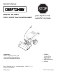
Operators Manual
LCRRFTSHRN"
I
H.P.
CHIPPER VAC SYSTEM
Model No, 486.24516
•
•
•
•
•
CAUTION:
Before using this product,
read this manual and follow
all Safety Rules and
Operating Instructions.
Sears, Roebuck and Co., Hoffman
www.searS.com/craftsman
PRINTED IN U.S,A,
Estates,
IL 60179
Safety
Assembly
Operation
Maintenance
Parts
U.S.A.
FORM NO. 47813 (8/00)
WARRANTY ...............................................................
2
SAFETY RULES ........................................................
3
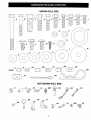
FULL SIZE HARDWARE CHART ............................. 6
CARTON CONTENTS ...............................................
8
ASSEMBLY ................................................................
9
OPERATION ............................................................
19
MAINTENANCE .......................................................
22
LIMITED
WARRANTY
ON CRAFTSMAN
SERVICE AND ADJUSTMENTS ............................ 23
STORAGE ................................................................
23
TROUBLESHOOTING
............................................. 24
REPAIR PARTS ILLUSTRATIONS
............ 25,26,27
REPAIR PARTS LISTS ................................ 25,27,28
SLOPE GUIDE .........................................................
29
PARTS ORDERING/SERVICE
............... Rear Cover
POWERED
TRACTOR
ATTACHMENTS
For one (1) year from the date of purchase, if this Craftsman Equipment is maintained, lubricated
and tuned up according to the instructions in the owner's manual, Sears will repair or replace free
of charge any parts found to be defective in material or workmanship. Warranty service is available free of charge by returning your Craftsman equipment to your nearest Sears Service Center.
In-home warranty service is available but a trip charge will apply. This Warranty applies only
while this product i_ in the United States.
This Warranty
•
does not cover:
Expendable items which become worn during normal use, such as spark plugs, air cleaners,
belts, and oil filters.
• Tire replacement or repair caused by punctures from outside objects, such as nails, thorns,
stumps, or glass.
•
•
Repairs necessary because of operator abuse, including but not limited to, damage caused by
impacting objects that bend the frame or crankshaft, or over-speeding the engine.
Repairs necessary because of operator negligence, includin_ but not limited to, electrical and
mechanical damage caused by improper storage, failure to use the proper grade and amount
of engine oil, or failure to maintain the equipment according to the instructions contained in the
owner's manual.
•
Engine (fuel system) cleaning or repairs caused by fuel determined to be contaminated
oxidized (stale). In general, fuel should be used within 30 days of its purchase date.
• Equipment used for commercial or rental purposes.
LIMITED WARRANTY
or
ON BATTERY
For ninety (90) days from date of purchase, if any battery included with the equipment proves
defective in material or workmanship and our testing determines the battery will not hold a
charge, Sears will replace the battery at no charge. Warranty service is available free of charge
by returning your Craftsman equipment to your nearest Sears Service Center. In-home warranty
service is available but a trip charge will apply. This Warranty applies only while this product is in
the United States.
TO LOCATE THE NEAREST
SEARS SERVICE CENTER
SIMPLY CONTACT
SEARS AT 1-800-4-MY-HOME.
This warranty gives you specific
state to state.
legal rights,
OR TO SCHEDULE
and you may also have other
SERVICE,
rights, which vary from
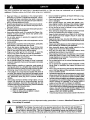
Any power equipment can cause injury if operated improperly or if the user does not understand how to operate the
equipment. Exercise caution at all times, when using power equipment.
•
•
•
•
•
•
•
•
•
•
•
•
•
•
•
Read and follow all instructions in this manual before
attempting to assemble or operate this equipment. Failure
to comply with these instructions may result in personal
injury. Keep this manual in a safe place for future reference
and for ordering replacement parts.
Read this operating and service instruction manualcarefully.
Be thoroughly familiar with the controls and proper use of
this power vacuum.
Read the vehicle owners manual and vehicle safe operation
rules before using this equipment.
Never allow children under 16 to operate this Chipper Vac.
Children 16 years and older should only operate under
close parental supervision.
Do not allow anyone to operate this equipment without
proper instructions.
Do not allow passengers to ride on this equipment or on the
towing vehicle.
Keep the area of operation clear of all persons, particularly
small children. Also keep area clear of pets.
•
Check fuel before starting,,, engine. Do not fill fuel tank
indoors, or when engine is running, or while engine is hot.
Wipe off any spilled fuel before starting engine.
Engine and muffler get hot. Do not touch! To avoid fire
hazard, keep clean of debris and other accumulations.
Never store Chipper Vac with fuel in tank. Allow engine to
cool before storing in any enclosure.
Do not change engine governor settings.
Do not operate engine it air cleaner or cover is removed,
except for adjustment. Removal of these parts could create
a fire hazard.
•
Before cleaning, repairing or inspecting, make certain all
moving parts come to a complete stop. Disconnect spark
plug wire and keep wire away from plug to prevent accidental starting. Keep throttle control lever in stop position.
If the Chipper Vac should become blocked with debris at
any point, shut engine off and wait until the impeller comes
to a complete stop before attempting to remove the obstruction. Disconnect spark plug wire to prevent accidental
starting.
If the cutting mechanism strikes a foreign object, or if your
Chipper Vac should start to vibrate abnormally, stop the
engine immediately, disconnect the spark plug wire and
move the wire away from the spark plug. Allow the machine
to stop and take the following steps.
a. Inspect for damage.
b. Repair or replace any damaged parts.
c. Check for loose parts and tighten to assure
continued safe operation.
Check all bolts for tightness at frequent intervals to help
insure safe operation.
Check vinyl hard top boot frequently for wear. Replace if
worn or damaged.
Never operate Chipper Vac unless deck adapter, hose,
hose adapter (nozzle), discharge chute (elbow), chipper
chute and top cover are properly attached in their place.
Do not remove top cover or attempt to empty contents of
cart while engine is running.
Never attempt to change hose adapter (nozzle) or to install
remote hose attachment when engine is running.
Keep all shields and guards (e.g. chipper chute, discharge
chute (elbow) and hose adapter (nozzle) in place and
securely attached.
Keep hands, feet, face, long hair and clothing out of inlet
and discharge area. There are ROTATING BLADES inside
these openings.
Always wear safety glasses or otheJ'suitable eye protection
when operating or maintaining this equipment.
Wear protective gloves when feeding material into the
chipper chute. Avoid loose fitting clothing.
Keep face and body clear of the chipper chute to avoid
accidental bounce back of any material.
•
•
•
•
•
•
•
•
•
When feeding material into this equipment, be extremely
careful that pieces of metal, rocks, bottles, cans or other
foreign objects are not included. Personal injury or damage
to the machine could result.
•
Do not stand behind cart in exhaust discharge area while
engine is running.
Do not operate this equipment while intoxicated or while
taking drugs or medication that impairs the senses and
reactions.
•
•
•
•
•
•
When using this equipment, start with the vehicle transmission in first (low) gear and then gradually increase speed
only as conditions permit.
Operate this equipment at reduced speed on rough terrain,
along creeks and ditches and on slopes to prevent tipping
or loss of control. Do not drive too close to a creek or ditch.
Vehicle braking and stability are affected by the addition of
this equipment. Do not fill the Chipper Vac to its full capacity
without checking the capability of the towing vehicle to
safely pull and stop with the Chipper Vac attached.
Before operating on any grade (hill) refer to the safety rules
in the vehicle owner's manual concerning safe operation on
slopes. Also refer to the SLOPE GUIDE on page 27 of this
owner's manual. Do not operate on slopes in excess of 10
degrees. STAY OFF STEEP SLOPES.
Follow the maintenance instructions outlined in this manual.
Look for
this is
symbol
to point out important safety precautions.
Your
safety
involved.
It means*-Attentlonl!
Become
alert!!
I
&
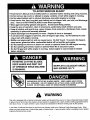
DANGER: This Chipper Vac was built to be operated according to the rules for safe operation in
this manual. As with any type of power equipment, carelessness or error on the part of the operator can result in serious injury. This unit is capable of amputating fingers and hands and throwing
objects. Failure to observe the following
safety instructions could result in serious injury or death.
I
TO AVOID SERIOUS INJURY
•
•
•
•
Read Owner's Manual and all safety labels on machine before starting and using machine.
Do Not remove top cover or attempt to empty contents of cart while engine is running.
Do Not stand behind cart in exhaust discharge area while engine is running.
Keep hands, feet, face, long hair and clothing out of chipper inlet, vac inlet, and discharge
area. There are ROTATING BLADES inside these openings.
• Wear approved safety glasses and gloves. Avoid loose fitting clothes.
• Keep the area of operation clear of all persons, particularly small children and pets.
• Keep all sh!elds and guards (e.g. upper chipper chute extens,on, discharge chute, nozzle
assembly) m place and securely attached.
• Check discharge boot frequently for wear. Replace if worn or damaged.
• If unit becomes clogged or jammed, shut off engine right away. Do Not attempt to clear
clog or jam with engine running.
• Muffler and engine get hot and can cause burns. Do Not Touch. To avoid a fire hazard,
keep leaves, grass and other combustible
debris off hot muffler and engine.
• Do Not attempt to remove or attach vac nozzle or optional Hose Kit with engine running.
• Do Not operateJJnit unless nozzle or optional Hose Kit is secured in place.
• Do Not fill gas tank while engine is running. Allow engine to cool at least 2 minutes
before refueling.
ROTATING CUTTING BLADES.
KEEP HANDS AND FEET OUT
OF OPENINGS WHILE MACHINE
IS RUNNING.
MUFFLER & ADJACENT
MAY EXCEED 150 o F
AREAS
WARNING
This unit is equipped with an internal combustion engine and should not be used on or near unimproved forest-covered,
or grass-covered land unless the engine's exhaust system is equipped with a spark arrester meeting applicable local or
state laws (if any). If a spark arrester is used, it shoutd be maintained in effective working order by the operator.
In the State of California the above is required by law (Section 4442 of the California Public Resources Code). Other
states may have similar laws. Federal laws apply on federal lands. A spark arrester muffler is available at your nearest
engine authorized service center.
4
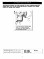
These accessories were available when the unit was purchased. They are also available at most Sears retail
outlets and service centers. Most Sears stores can order repair parts for you when you provide the model
numbers of your tractor and Chipper Vac System.
L
,,-
\\
x,
i II
I
The Hand Wand Attachment, Model 486.24509
provides a 15' x 5" diameter hose to clean
around shrubs, patios, window wells and other
areas not accessible to the tractor.
The model and serial numbers will be found on a decal
attached to the engine base.
You should record both the serial number and the date of
purchase and keep in a safe place for future reference.
I
I
MODEL NUMBER:
SERIAL NUMBER:
DATE OF PURCHASE:
486.24516
SHOWN
_y
_
.i BB
jAA
I
FULL SIZE
CC
KK
J
jEE
I
NOT SHOWN
II
7 DD
LL
FULL SIZE
MM
PP
RR
UU
6
jW
XX
ATTENTION!
Keep contents
of each hardware
package
separate
for easier
assembly.
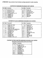
CONTENTS OF HARDWARE PACKAGE IN CART CARTON
Ref. Qty.
A
B
D
J
M
O
P
Q
R
X
3
2
2
9
14
11
14
5
2
4
Description
Ref. Qty.
Description
Bolt, Hex 3/8" x 3"
Bolt, Hex 1/4" x 1-3/4"
Bolt, Hex 3/8" x 1-1/4"
Bolt, Hex 1/4" x 5/8"
Bolt, Truss Head 5/16" x 3/4"
Lockwasher, 1/4"
Lockwasher, 5/16"
Lockwasher, 3/8"
Flat Washer, 1/4"
Flat Washer, 1=
Z
BB
EE
GG
HH
II
JJ
KK
NN
Hex Nut, 1/4"
Hex Nut, 5/16"
Nut, Hex Lock 3/8"
Pin, Cotter 1/8" x 1-1/2"
Hair Cotter Pin, 1/8"
Hub Cap
Spacer Tube
Door Support
Hitch Pin
CONTENTS
Ref.
Qty.
C
E
G
H
J
L
N
O
P
R
S
T
U
V
W
1
2
4
6
30
4
2
40
4
26
6
3
4
1
4
OF (2) VAC HARDWARE
11
14
5
2
1
2
2
2
1
PACKAGES
IN VAC CARTON
Description _
Ref.
Qty.
Description
Hex Bolt, 1/2" x 1-1/4"
Hex Bolt, 1/4= x 1-1/4"
Hex Bolt, 1/4" x 1"
Hex Bolt, 5/16" x 3/4"
Hex Bolt, 1/4" x 5/8"
Hex Bolt, 5/16" x 3/4" Thread Forming
Truss Bolt Head, #10-32 x 5/8"
Lock Washer, 1/4"
Lock Washer, 5/16"
Flat Washer, 1/4"
Nylon Washer
Flat Washer, 5/16"
Flat Washer, 3/8"
Flat Washer, 7116"
Flat Washer, 11/32" x 1-1/2"
Y
Z
AA
DD
EE
FF
LL
MM
OO
PP
QQ
RR
SS
TT
UU
2
46
2
9
2
1
1
3
1
2
2
Hex Nut, #10-32
Hex Nut, 1/4"
Hex Lock Nut, 1/4"
Nylock Nut, 5/16"
Hex Lock Nut, 3/6"
Hex Lock Nut, 1/2"
Hitch Plate
Knob
Tarp Strap, 25"
Tarp Strap (Less Hooks)
"S" Hooks
2
1
1
3
Eye Bolt
Door Latch (RH)
Door Latch (LH)
Hinge
CONTENTS OF DECK ADAPTER HARDWARE PACKAGE IN VAC CARTON
Not all parts in this list will be used for any one tractor.
Ref.
Qty.
F
I
K
R
S
T
AA
CC
VV
WW
XX
2
3
2
3
3
12
3
3
1
1
1
Description
Hex Bolt, 5/16" x 1•
Hex Bolt, 1/4" x 3/4'
Cardage Bolt, 5/16" x 3/4"
Flat Washer, 1/4"
Nylon Washer
Flat Washer, 5/16"
Hex Lock Nut, 1/4"
Hex Lock Nut, 5/16"
Mounting Strap
Angle Bracket
Mounting Bracket
10
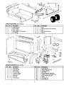
CARTON
Ref.
1
2
3
4
5
CONTENTS
Qty.
1
1
1
1
2
(Cart Carton)
Description
Wheel Support
Rear Tongue
Front Tongue
Hose Hanger Rod Assembly
Cart Bodies
Ref.
Qty.
6
7
8
9
10
1
1
1
1
2
Description
Hose
Tailgate Reinforcement Bracket
Axle
Latch Stand Bracket
Wheels
/
17
12
CARTON CONTENTS
Ref.
1
2
3
4
5
6
7
8
9
Qty.
1
2
2
1
1
1
1
2
2
(Vac Carton)
Description
Front Panel
Side Brackets
Side Panels
Dump Handle
Prop Rod (Right)
Prop Rod (Left)
Rear Door
Tie Rods
Hose Clamps
Ref.
10
11
12
13
14
15
16
17
18
19
Qty.
1
1
1
1
1
1
1
1
1
1
Description
Deck Adapter
Hose Hanger Bracket
Adapter Bracket
Skid Plate
Engine/Impeller Assembly
Chipper Chute w/Tamper Plug
Hose Adapter (Nozzle)
Elbow
Poly Hard Top
Hitch Bracket
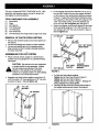
This unit is shipped WITHOUT GASOLINE or OIL. After
assembly, see separate engine manual for proper fuel
and engine oil recommendations.
TOOLS
REQUIRED
•
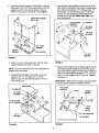
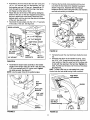
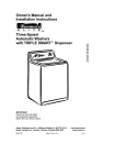
Fit the tailgate reinforcement bracket over the end of
the cart bed. Position the two door support brackets
on the bottom of the reinforcement bracket as shown
in figure 2. Fasten the reinforcement bracket and the
door supports to the bottom of the cart using six 5/16"
x 3/4" truss head screws, 5/16" lock washers and
5/16" hex nuts. Do not tighten yet. See figure 2.
Fasten the tailgate reinforcement bracket to the sides
of the cart body using four 1/4" x 5/8" hex bolts, 1/4"
lock washers and 1/4" hex nuts as shown in figure 2.
Do not tighten yet.
FOR ASSEMBLY
(1)
(1)
(1)
(2)
(2)
(2)
Screwdriver
Pliers
3/8" Wrench
7/16" Wrenches
1/2" Wrenches
9/16" Wrenches
(2)
3/4" Wrenches (only if figure 28 on page 16 is used)
•
1/4" HEX NUT
REMOVAL
•
•
•
THE
VAC
&
114" LOCK
WASHER
1_"x5/8"
HEX BOLT
Q
_16"x _4"TRUSS
HEADSCREW
/
SYSTEM
DOOR
SUPPORT
Place cart body halves upright on a smooth level
surface such as a garage floor or a paved driveway.
See figure 1.
CAUTION:
•
FROM CARTONS
Remove the hardware packs and all loose parts from
the cartons.
Lay out and identify parts shown in carton contents.
Lay out and identify parts in the hardware packs.
Keep contents of each hardware package separate
for easier assembly.
ASSEMBLING
•
OF PARTS
Do not leave the cart unattended
• "l _
in upright position during assembly. A falling
cart can cause personal injury! Pay close
attention to the stability of the cart while it
remains in an upright position. For best stability,
assemble on a smooth level surface.
_16"
HEX NUT
_16"LOCK
WASHER
TAILGATE
REINFORCEMENT
BRACKET
FIGURE 2
•
Assemble cart body halves together using three 1/4"
x 5/8" hex bolts, 1/4" lock washers and 1/4" hex nuts
as shown in figure 1. Do not tighten yet.
•
1/4" x 5/8"
HEX BOLT
Pull the cart body halves together.
Tighten the six tr_Jsshead screws in figure 2.
Tighten the four hex bolts in figure 2.
Tighten the three hex bolts in figure 1, keeping the
bottom aligned and pulled together.
Carefully flip the cart end for end so that it rests on
the tailgate reinforcement bracket. See figure 3.
1/4" HEX NUT
FIGURE 1
FIGURE 3
9
•
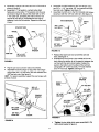
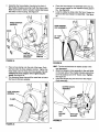
Assemble the wheel support to the bottom of the cart
using eight 5/16" x 3/4" truss head screws, 5/16" lock
washers, and 5/16 hex nuts as shown in figure 4.
Heads of screws go on the inside of cart. Tighten.
Align the latch stand bracket so that the tab is at the
rear. Fasten the bracket to the rear set of holes at the
front of the cart using two 1/4" x 5/8" hex bolts, 1/4"
flat washers, 1/4" lock washers, and 1/4" hex nuts.
Use the 1/4" flat washers as shims between the
bracket and the cart bed. Make finger tight at this
time. See figure 6.
TRUSS HEAD SCREW
5/16" x 3/4"
LATCH STAND
(Tabatrear)
BRACKET
1_" HEX NUT
I_"LOCK
WASHER
_/
I_"FLAT
"5/16" LOCK
WASHER
WHEEL
SUPPORT
_16"HEX
\
NUT
1/4" x 5/8"
HEX BOLT
FIGURE 4
•
FIGURE 6
Lower the cart to rest upside down, with the wheel
support facing up, as shown in figure 5.
Place the rear tongue onto the wheel support and the
latch stand bracket. Assemble the axle through the
ends of the wheel support and the tongue. Fasten the
axle to the wheel support using two 1/4" x 1-3/4" hex
bolts, 1/4" lock washers and 1/4" hex nuts. Tighten.
See figure 7. -
NOTE: The parts assembled in the next paragraph are
shipped in the Vac carton.
Assemble the skid plate to the bottom of the cart
using two 1/4" x 1" hex bolts, four 1-1/2" flat
washef._, two 1/4" lock washers and two 1/4" hex
nuts. See figure 5.
IMPORTANT:
Make sure the tongue is securely locked
to the latch stand bracket by the latch lock lever.
SKID PLATE
1/4" x 1-3/4"
HEX BOLT
1/4" HEX NUT
114"LOCK
WASHER
/'2
_
--
AXLE
.
TONGUE
(REAR)
1-1/2" x 11/32"
FLAT WASHER
_" 1/4" LOCK WASHER
1/4" x 1"
HEX BOLT
"_
FIGURE 7
FIGURE 5
10
1/4" HEX NUT
•
Assemble a spacer tube onto each end of the axle as
shown in figure 8.
Assemble a 1" flat washer, a wheel (valve stem
facing out), and another 1" flat washer onto the axle
as shown in figure 8. Secure the wheel with a 1/8" x
1-1/2" cotter pin, spreading the ends so that a hub
cap will fit over the pin. Assemble the hub cap by
pressing it onto the flat washer. Repeat on other end
of axle.
•
•
Assemble the hitch bracket to the front tongue using
two 3/8" x 1-1/4" hex bolts, 3/8" lock washers and 3/8"
hex lock nuts. Tighten. See figure 10.
•
Assemble the hitch pin to the hitch bracket and tongue,
securing it with the 1/8" hair cotter pin. See figure 10.
HITCH BRACKET
SPACERTUBE
HITCH
PIN
HEX
3/8" xBOLT
1-1/4".........,.,_
WHEEL
\
1" FLAT
1/8" HAIR
COTTER
PIN
WASHER
\
.t J
G
TONGUE
T
1" FLAT
WASHER
FIGURE 10
lib
HUB CAP
1/8" x %1/2"
COTTER PIN
Release the latch lock lever and tilt the cart bed
back. See figure 11.
Assemble the front panel to the outside of the cart
bed, sliding the bottom lip of the panel in between the
cart bed and the latch stand bracket. Fasten the
panel to the bottom and the sides of the cart bed
using eight 1/4" x 5/8" hex bolts, 1/4" lock washers
and 1/4" hex nuts. Tighten. See figure 11.
FIGURE 8
•
•
Flip the cart over so that it rests on its wheels.
Assemble the front tongue on top of the rear tongue
using three 3/8" x 3" hex bolts, 3/8" lock washers and
3/8" hex lock nuts. See figure 9.
HINT: For easier assembly, support the rear tongue with
a block of wood.
\
I_"LOCK
WASHER
\
FRONT
PANEL
I_"HEXNUT
\
3/8" X 3"
HEX BOLT
'"
_8"LOCK
WASHER
3/8"HEX
LOCKNUT
1_"x5/8"
HEXBOLT
1/4"x5_"
HEXBOLT
TONGUE
_
LATCH
STAND
:'
\
BLOCK
FIGURE 11
FIGURE 9
•
11
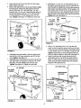
Tighten the two bolts which were assembled to the
latch stand bracket in figure 6.
Lower the front of the cart and lock it to the tongue
with the latch lock lever.
Assemble a 1/4" hex nut, 1/4" lock washer and 114"
flat washer onto each end of a tie rod. Insert the rod
Place a side panel down onto the cart, fitting it inside
the front panel. Fasten the side panel to the front
panel using three 1/4" x 5/8" hex bolts, 1/4" lock
washers and 1/4" hex nuts. Fasten the side panel to
the cart bed flange using two 1/4" x 5/8" hex bolts,
1/4" flat washers, 114" lock washers and 1/4" hex
nuts. Tighten. See figure 12. Repeat on other side.
ends through the middle hole in each side panel and
side bracket. Assemble another 1/4" flat washer, 1/4"
lock washer and 1/4" hex nut onto each end of the tie
rod. Adjust the hex nuts to make the sides the same
distance apart at the middle of the cart as at the front.
Tighten the nuts. See figure 14.
1/4" LOCK
WASHER
I_"HEX
_.,_HEX
114" TIE ROD
HEX
NUT
NUT
BOLT
I_"LOCK
WASHER
1/4"x _8"
HEX BOLl
FIGURE 14
•
FIGURE 12
Assemble the dump handle to the front panel using
two #10-32 x 5/8" truss head bolts and # 10-32 hex
nuts. Tighten. See figure 13.
Assemble the a side bracket to the front hole and the
two rear holes in a side panel. Use three 1/4" x 5/8"
hex bolts, 1/4" lock washers and 1/4" hex nuts.
Tighten. See figure 13. Repeat for other side.
•
Place a 1/4" flat washer onto a 1/4" eye bolt and
insert the bolt through the second hole from the front
in the side panel and side bracket. Assemble another
1/4" flat washer and a 1/4" hex lock nut onto the bolt.
Tighten, leaving the nut loose enough that the eye
bolt turns freely. Repeat on other side. See figure 15.
Insert the left prop rod through the eye bolt and
temporarily rest it on top of the tie rod as shown in
figure 15. Make sure the hook end of the prop rod
points dowg and the threaded end points outward.
Repeat for the right prop rod.
114"HEX NUT
WASHER
114"LOCK
DUMPHANDLE
J
114"HEX
LOCK NUT
FIGURE 13
FIGURE 15
12
:_
•
Assemble a 1/4" hex nut and then a 1/4" flat washer
onto each end of a tie rod. Insert the rod ends through
the upper holes in the sides of the hardtop. Assemble
another 1/4" flat washer and 1/4" hex nut onto each
end of the tie rod. Adjust the hex nuts to make the
distance between the sides approximately the same
front to rear. Tighten the nuts. See figure 16.
Assemble the three hinges to the front of the hard top
using six 1/4" x 5/8" hex bolts, 1/4" flat washers, 1/4"
lock washers and 1/4" hex nuts. Assemble the bolts
and flat washers from the bottom. See figure 16.
•
114"FLAT
Place a 3/8" flat washer onto the end of the right prop
rod and insert the rod into the lower hole in the side of
the hardtop. Assemble a 3/8" flat washer and a 3/8"
hex lock nut onto the rod on the outside of the hard
top. Tighten the nut and then loosen 1/2 turn. See
figure 18. Repeat for the left prop rod.
\
1/4" HEXNUT
\
114"LOCK \
1/4" HEXNUT
WASHER /
WASHER.
\
3/8" H_
LOCK NUT
#
1,4"H X.UT
' 1,44J
1HI.O
x/+
TIE ROD
FIGURE 18
HEX BOLT
Lower the hard top. If it does not fit down easily into
the "Z" brackets, adjust the width of the hardtop by
adjusting the nuts on the tie rod. See figure 19.
Screw a 1/4" hex nut approximately half way onto a
1/4" x 1" hex bolt. Insert the bolt into the hole in the
side of the cart as shown in figure 19. Fasten the bolt
to the cart using a 1/4" lock washer and 1/4" hex nut.
Tighten so that the nut is even with the end of the
bolt, Repeat on the other side. See figure 19.
FIGURE 16
Assemble the right hand and left hand door latches to
the back of the hard top using two 5/16" x 3/4" hex
bolts, nylon washers and 5/16" nylock nuts. Place the
nylon washer beneath the door latch. Tighten so that
the latch is snug but wifl still rotate. See figure 17.
POLY HARDTOP
DOOR LATCH
(LEFT HAND)
\
5/16" NYLOCK NUT
NYLON WASHER
5/16" x 3/4"
HEX BOLT
DOOR LATCH
(RIGHT HAND)
FIGURE 17
114" LOCK
WASHER
•
Mount the hard top to the cart by inserting the hinges
into the slots in the front panel of the cart, See figure
18.
FIGURE 19
13
114" HEX NUT
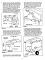
•
Assemble a short tie strap to the rear door using one
1/4" x 1-1/4" hex bolt, two 1/4" flat washers, one 1/4"
lock washer and one 1/4" hex nut. Assemble an "S"
hook through the loose end of the strap. See figure
20. Repeat on other side of door.
Attach the door to the rear of the cart by resting the
bottom of the door on the door supports and pushing
the top in against the cross brace. Swivel the door
latches down until they lock into the slots in the sides
of the cart. See figure 20.
Hook both the tarp straps onto the 1/4" x 1" hex bolts
in the sides of the cart. See figure 20.
•
•
Remove the hex bolts, lock washers and hex lock
nuts from the two holes in the impeller housing as
shown in figure 22. Assemble the hose hanger
bracket to the two holes using the bolts, lock washers
and lock nuts which you removed.
USE THESE
HOLES
HOSE
HANGER
BRACKET
DOORLATCHES
USE PREBOLTS, LOCK
WASHERS AND
HEX LOCK
NUTS
114"FLAT
WASHER
FIGURE 22
WASHER
1/4" HEX NUT
"_
DOOR
SUPPORTS
•
1/4" x 1"
HEX BOLT
•
FIGURE 20
•
Assemble the engine base assembly to the welded
angles on the tongue using four 5/16" x 3/4" hex bolts,
5/16" lock washers and 5/16" nylock nuts. Tighten
the bolts securely. See figure 21.
NOTE: Use the upper holes in the welded angles.
Temporarily push the vinyl boot back inside the hard
top.
Assemble the elbow to the impeller housing, using
four 5/16" x 3/4" thread forming hex bolts, and four
nylon washers. Align the upper end of the elbow side
to side with the opening in the hard top. Tighten the
bolts. Pull the boot forward over the end of the elbow.
See figure 23_
HINT: To start a bolt into an unthreaded hole, push
the bolt into the hole while turning it with a wrench.
Align elbow
ELBOW
NYLON
WASHER
_16"x _4"
HEX BOLT
(Thread Forming}
WELDED
ANGLES
FRONT
TONGUE
FIGURE 21
FIGURE 23
14
Assemble the bose adaptor (nozzle) to the front of
the impeller housing, securing it with the three knobs.
Make sure that the switch actuator bracket depresses
the switch on the housing. See figure 24.
•
Place the hose hanger rod assembly down into the
hose hanger bracket on the impeller housing assembly. See figure 26.
Loop the rubber tie strap under the hose. Fasten the
hooks to the hose hanger rod assembly. See figure
26.
•
HOSE ADAPTER
(NOZZLE)
KNOB
HOSE HANGER
ROD ASSEMBLY
1
25"TARP
STRAP
SW_CH
ACTUATOR
BRACKET
SAFETY
SW_CH_
FIGURE 24
FIGURE 26
•
•
HINT: Tip the cart bed back for easier access in the
next paragraph.
• Attach the chipper chute assembly to the weld bolts
on the back side of the impeller housing using three
Place a hose c_amp onto the end of the hose. Push
the hose onto the hose adapter (nozzle). Tighten the
hose clamp onto the hose and hose adapter. Do not
collapse the hose adapter when tightening the
clamp. See figure 25,
The remaining hose clamp will be used later to fasten
the hose to the deck adapter.
•
5/16" flat washers and 5/16" Nylock nuts. Tighten.
See figure 27. insert the tamper plug into the end of the chipper
chute assembly.
CHIPPER CHUTE
ASSEMBLY
HOSE ADAPTER
(NOZZLE)
CLAMP
_16"
NYLOCK
NUT
FIGURE 27
FIGURE 25
15
_16" FLAT
WASHER
•
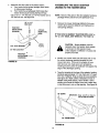
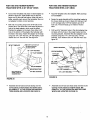
ASSEMBLING THE DECK ADAPTER
(#62468) TO THE MOWER DECK
Assemble the hitch plate to the tractor hitch if:
a. Your tractor has a square (straight) hitch frame,
to help prevent binding.
b. Your tractor has a lightweight hitch frame that
needs reinforcing for towing the Mow-N-Vac.
Use a 1/2" x 1-1/4" hex bolt, a 7/16" flat washer and a
1/2" hex lock nut. See figure 28.
NOTE: Not all of the parts in the deck adapter hardware
package will be used for any one particular fit up.
1/2" x 1-1/4"
HEX BOLT
TRACTOR
HITCH FRAME
1
(_
(SQUARE)
_
7/16" FLAT WASHER
•
A'FI'ACH
MOW-N-VAC
HERE
HITCH
PLATE
j
IF YOU HAVE A MURRAY TRACTOR WITH A 38", a
40" or a 46" DECK, SKIP DIRECTLY TO PAGE 18.
:
:
..°',
,
!I
.• j"
""
CAUTION:
Mower deflector must be
replaced when Vac System deck adapter
is removed. Do Not operate mower
unless adapter or deflector is in place and
properly mounted.
&
i
1/2" HEX LOCK NUT
TRACTOR
HITCH FRAME _'(TAPERED)
Remove the mower discharge deflector from your
mower deck. Save the deflector and hardware for
remounting deflector.
4,
,?
'
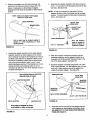
Identify your mower deck (see fold outs) and cut out
the correct discharge opening template for your
mower deck size. If there is no template for your
deck size you can make your own template by
marking around a piece of cardboard held against the
edge of the discharge opening.
FIGURE 28
Tape the template to the face of the adapter, locating
template approximately 1/2" from front and 1/4" down
from top of adapter. Keep as close to top as possible.
See figure 29. Mark outline of template on face of
adapter using white crayon, nail or scriber. Ddll a
starting hole inside the outline, then use a saber saw
or key hole saw to cut out the opening. See figure 29.
114" DOWN
IMPORTANT:
I_"FROM
FIGURE 29
16
FRONT
Keep cut-off as close to
the top edge as possible.
•
Position the adapter over the deck opening, and
check for fit of cutout as shown in figure 30. Trim
cutout, if necessary, to allow tilting of adapter,
keeping the fit as close as possible for best vacuum
suction.
NOTE:
Assemble the adapter bracket to the deck using two
5/16" x 1" hex bolts, 5/16" flat washers and 5/16" hex
lock nuts. See figure 32.
NOTE: It may be necessary to use extra 5/16" flat
washers to shim under the bracket next to the deck
surface. Ten extra washers have been furnished as
Make sure adapter clears gauge
wheels on mower deck
shims. See figure 32.
,
.I.
(2) 5/16" HEX
LOCK NUTS
I
_
_-_.._
_-,,---
(2) 5/16" FLAT
WASHERS
_
DECK ADAPTER
ADAPTER BRACKET
Curl on deck may be located outside of
adapter or inside depending on deck
opening design
FIGURE 30
i_
5/16" flat washers
5/16" x 1" HEX BOLT
,,,,f_
used as needed for
shims to adjust for
variations in decks.
.
FIGURE 32
Holding the adapter bracket and the deck adapter
together, position the deck adapter on the mower
deck. Keeping the edge of deck adapter as close as
possible to the offset in the adapter bracket, see if
the slot in the adapter bracket can be aligned with
one or two of the deflector holes in your mower
deck's discharge opening. If the bracket can not be
located correctly using existing holes, it will be
necessary to drill one or two 5/16" diameter holes in
the deck. See figure 31.
With deck adapter positioned correctly over the
discharge opening, use the adapter bracket as a
template and drill three 9/32" diameter holes in the
top of the deck adapter. See figure 33.
Bolt deck adapter to bracket using three 1/4" x 3/4"
bolts, nylon washers, 1/4" flat washers and 1/4" hex
lock nuts. Nyk)n washers should be against the
inside of the ddck adapter. See figure 33.
Use existing holes or drill 5116"
diameter hole or holes.
DECK ADAPTER
(3)I_"HEX
LOCK NUTS
ADAPTER BRACKET
ADAPTER
BRACKET
(3) NYLON
WASHERS
(3) I_"STEEL
MOWER DECK
WASHERS
_)l_"x
DECK ADAPTER
5/4"HEXBOLTS
FIGURE 33
MOWER DECK
Keep edge of adapter as close
as possible to offset in bracket
Assemble end of hose and a hose clamp over the
round opening of deck adapter and tighten clamp.
GO DIRECTLY TO THE OPERATION INSTRUCTIONS ON PAGE 19.
FIGURE 31
17
FOR 1990 AND NEWER MURRAY
TRACTORS WITH A 38" OR 40" DECK
FOR 1990 AND NEWER MURRAY
TRACTORS
WITH A 46" DECK
Cut out two templates and place on deck adapter as
shown in figure 34. Tape smaller one on top and
larger one on the side and bottom. After they are in
place, carefully mark around the templates, then cut
out adapter to obtain correct opening.
•
Tape 46" template onto deck adapter. Mark and then
cut out adapter.
Fasten the angle bracket and the mounting bracket to
the mower deck as shown in figure 35. Use two 5/16"
x 3/4" carriage bolts, 5/16" flat washers and 5/16"
lock nuts. The bolt heads go on inside of mower
deck.
Bolt end of mounting strap to the 5/16" bolt on the
mower deck. The other end of the strap will bolt to a
hole in the deck adapter, which must be drilled.
Position the adapter on the deck, then drill a 5/16"
hole in the bottom of the adapter that will align with
the hole in the strap. Fasten the adapter to the strap
using one 1/4" x 3/4" hex bolt, 1/4" flat washer, nylon
washer and 1/4" hex lock nut. See figure 34.
Drill two 5/16" diameter holes in the deck adapter that
will align with the holes in the angle bracket and the
mounting bracket. Assemble the deck adapter to both
brackets using two 1/4" x 3/4" hex bolts, 1/4" flat
washers, nylon washers and 1/4" hex lock nuts. See
figure 35.
TEMPLATE TO CUT OUT SLOT
38"/40" TEMPLATE
_"
CUT OUT SLOT IN TOP
OF DECK ADAPTER
ANGLE BRACKET
114" x 3/4" HEX BOLT
\\
/\
"_1/4 HEX LOCK NUT
NYLON WASHER
1/4" FLAT WASHER
MOUNTING
1/4" FLAT
HEX BOLT
NYLON WASHER
BOLT THIS END OF
STRAP TO 5/16" DOLT
ON MOWER DECK
Ny._N WASHER
1/4" HEX LOCK NUT
FIGURE 35
FIGURE 34
Assemble end
round opening
GO DIRECTLY
TIONS WHICH
of hose and hose clamp over the
of deck adapter and tighten clamp.
TO THE OPERATION INSTRUCARE LOCATED ON PAGE 19.
Assemble end of hose and hose clamp over the round
opening of deck adapter and tighten clamp. GO
DIRECTLY TO THE OPERATION INSTRUCTIONS
WHICH ARE LOCATED ON PAGE 19.
18
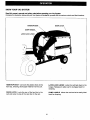
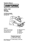
KNOW
YOUR
VAC
SYSTEM
Read this owner's manual and safety rules before operating your Vac System.
Compare the illustration below with your Vac System to familiarize yourself with the various controls and their locations.
HARDTOPBOOT
DOOR LATCH
LATCH LOCK LEVER
\
I
HARDTOP BOOT Connects the plastic elbow to the
hard top, directing discharged material into the cart.
LATCH LOCK LEVER
Locks the cart bed down to the
DOOR LATCH Locks the rear of the hard too to the
cart and locks the top of the rear door to the cart.
DUMP HANDLE Allows the cart bed to be easily tilted
back for dumping.
tongue. Releases to allow cart to be tipped back for
dumping.
19
BEFORE
•
HOW TO USE YOUR
STARTING
Your Chipper Vac System engine is shipped without
oil or gasoline. Service the engine with oil and gas as
instructed in the separate engine manual.
Inspect the Vac System to make sure all covers (rear
door, hardtop boot, elbow, hose adapter, hose and
deck adapter are properly attached.
Check tires for proper inflation (12 - 14 Ibs).
•
•
HOW
•
TO STOP
YOUR
CHIPPER
VAC
•
To stop engine, move the throttle control lever to the
OFF position.
Disconnect spark plug wire from plug to prevent
accidental starting while equipment is unattended or
is being worked on.
•
Inspect the Chipper Vac to make sure all covers (rear
door, hard top boot, elbow, chipper chute with tamper
plug, hose adapter (nozzle), hose and deck adapter
are properly attached.
Check tires for proper inflation (12 - 14 Ibs).
Check oil and gas in Chipper Vac engine.
Begin operation at low speed, adjusting forward speed
to match grass height and/or moisture condition to
prevent clogging.
Do not attempt to vacuum up any material other than
vegetation found in a normal yard, such as light
branches, leaves, twigs, etc.
•
•
•
with the engine running, or while the engine
WARNING:
Never fill fuel tank indoors, or
is hot. Do not smoke while filling tank.
&
CAUTION:
areas
are hot!r_e muffler and adjacent
HOW TO START
YOUR CHIPPER
•
•
•
•
MAC
MAC
CAUTION:
Vehicle braking and stability
may be affected with the addition of an
accessory or an attachment. Be aware of
changing conditions on slopes,
&
•
CHIPPER
WARNING:
Should your Chipper Vac
become clogged, shut off tractor and
Chipper Vac engines. Before attempting
to unclog, remove wire from spark plug to
prevent accidental starting.
To empty cart, shut off tractor engine and set brake.
Shut off Chipper Vac engine.
Remove rear door from cart.
Release latch lock lever on tongue and tip cart back.
See figure 36.
sure that no one is near the cart before
CAUTION:
To avoid possible injury, be
releasing the latch lock lever.
engine
without Never
all covers
WARNING:
start being
or runproperly
the
attached to the blower housing and cart.
'T"
•
•
•
•
•
•
•
•
Check oil and gas in Chipper Vac engine.
Attach spark plug wire to spark plug.
Move choke lever on engine to CHOKE position.
(A warm engine may not require choking.)
Move throttle control lever on engine to FAST position.
Grasp starter handle and pull rope out slowly until
engine reaches start of compression cycle (rope will
pull slightly harder at this point). Let the rope rewind
slowly.
Pull rope with a rapid, continuous, full arm stroke.
Keep a firm grip on starter handle. Let rope rewind
slowly. Do not let starter handle snap back against
starter.
Repeat instructions in two preceding paragraphs until
engine fires. When engine starts, move choke control
gradually to RUN position.
•
•
Lift rear of hard top and secure it in the upper raised
position with right and left prop rods.
Using a rake or suitable tool, pull grass clippings and/
or leaves out of cart.
After cart is emptied, close hard top, tip cart forward and secure it to the tongue. Reattach rear
door and hardtop boot.
FIGURE 36
2O
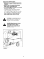
USING
•
•
•
•
THE
CHIPPER
CHUTE
Material such as stalks or heavy branches up to 3" in
diameter may be fed into the chipper chute as shown
in figure 37.
Be sure to wear eye protection and gloves when
feeding material into the chipper chute.
Use the tamper plug, not your hands, to force material
down through the chipper chute.
For best performance, it is important to keep the
chipper blades sharp. If the composition of the
material being discharged changes (becomes stringy,
etc.) or if the rate of discharge slows down considerably, it is likely that the chipper blades are dull and
need to be sharpened or replaced. Refer to the
Service and Adjustments section, on page 23.
&
WARNING:
Do not attempt to feed any
material larger than 3" in diameter into
the chipper chute. Personal injury or
damage to the machine could result.
&
DANGER:
Keep hands out of chipper
chute. Rotating blades in impeller
housing can cause serious injury. Use
the tamper plug to help push material
down into the chute.
FIGURE 37
21
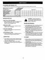
CUSTOMER RESPONSIBILITIES
• Read and follow the maintenancescheduleand the maintenanceprocedureslistedin thissection.
MAINTENANCE
SCHEDULE
Fill in dates as you
complete regular service.
Check for loose fasteners
_ "_ "_._'_.,,"_F
_
_,,J_'_
Service Dates
"_/"
X
Check soft vinyl boot
X
I Check tire pressure
X
Check engine oil level
X
Lubricate
X
Clean
X
X
Maintain engine per instructions below and in engine manual.
BEFOREEACH
USE
&
CHECK FOR LOOSE FASTENERS
• Make a thorough visual check of the Chipper Vac for
any bolt_ and nuts which may have loosened.
RetiaE_en any loose bolts and nuts.
ENGINE
CHECK VINYL BOOT
• Check the vinyl boot (on front of hardtop) for wear.
Replace if worn or damaged.
•
•
CHECK TIRE PRESSURE
•
Check tire pressure regularly. Recommended tire
pressure is 12-14 Lbs.
CHECK ENGINE OIL LEVEL
• Check oil level before each use. Maintain engine oil
as instructed in the separate engine manual.
•
LUBRICATION
•
•
WARNING:
Always stop engine and
disconnect spark plug wire before cleaning, lubricating or before performing any
repairs or maintenance.
MAINTENANCE
Check oil level before each use. Maintain engine oil
as instructed in the separate engine manual.
Service air cleaner every 25 hours under normal
conditions. Clean every few hours under extremely
dusty conditions. Poor engine performance and
flooding usually indicates that the air cleaner should
be serviced. To service the air cleaner, refer to the
separate engine manual.
The spark plug should be cleaned and the gap reset
once a season. Spark plug replacement at the start
of each seasoCl,is recommended, Check the engine
manual for correct plug type and gap specifications.
CLEANING
At the beginning of each season, lubricate the latch,
latch pivot bolt, and the axle where the hitch tongue
pivots, with a light machine oil.
At least once a season, grease or oil the wheel
bearings. Use automotive wheel bearing type grease
or 20 weight oil.
•
•
22
Make sure the cart, the sides and front panel and top
are cleaned after each use. Grass clippings and
leaves left in the cart will mildew and cause damage
if not cleaned out.
Clean the engine regularly-with a cloth or brush.
Keep the cooling fins on the engine housing clean to
permit proper air circulation which is essential to
engine performance and life. Be sure to remove all
dirt and debris from muffler area.
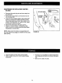
SHARPENING
BLADES
OR REPLACING
CHIPPER
NYLOCK NUTS
•
•
•
•
•
Disconnect the spark plug wire and move away from
the spark plug.
Remove the access plate by removing two hex lock
nuts. See figure 38.
Locate one of the chipper blades in the access plate
opening by rotating the impeller assembly by hand.
Remove the blade using a 3/16" allen wrench on the
outside of the blade and a 1/2" wrench on the impeller assembly, inside the housing.
Remove the other blade in the same manner.
Replace or sharpen blades. If sharpening, make
certain to remove an equal amount from each blade.
Reassemble in reverse order.
NOTE: Make certain the blades are reassembled with
FIGURE 38
the sharp edge facing upward, as viewed from the access
plate opening.
•
•
Clean the engine and the entire unit thoroughly.
Refer to engine manual for correct engine storage
instructions.
•
•
23
If storing in an unventilated or metal storage shed,
coat metal parts with light oil or silicone to prevent
rust.
Store unit in a clean, dry area.
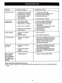
PROBLEM
POSSIBLE CAUSE(S)
CORRECTIVE ACTION
Engine fails to start
1.
2.
3.
4.
Spark plug wire disconnected.
Safety switch not contacted.
Fuel tank empty, or stale fuel.
Fuel shut-off valve closed
(if so equipped).
5. Faulty spark plug.
1,
2.
3,
4,
1. Spark plug wire loose
2. Unit running on CHOKE.
3. Blocked fuel line or stale fuel.
1. Connect and tighten spark plug wire.
2. Move choke lever to OFF position.
3. Clean fuel line; fill tank with clean
fresh gasoline.
4. Disconnect fuel line at carburetor ,'o drain
fuel tank. Refill with fresh fuel.
5. Adjust carburetor.*
6. Service air cleaner.*
Loss of power;
operation erratic.
5. Clean, adjust gap or replace.
4. Water or dirt in fuel system.
5. Carburetor out of adjustment.
6. Dirty air cleaner.
Engine overheats
Too much vibration
Unit does not
discharge
1. Carburetor not adjusted
pmpedy.
2. Engine oil level low.
1. Adjust carburetor.*
2. Fill crankcase with proper oil.
Loose parts or damaged
impeller.
Stop engine immediately and disconnect
spark plug wire. Tighten all bolts and nuts.
Make all necessary repairs. If vibration
continues, have unit serviced by an
authorized service dealer.
1. Discharge chute (elbow)
clogged.
1. Stop engine immediately and disconnect
spark plug wire. Clean inside of housing
and discharge chute (elbow).
2. Stop engine immediately and disconnect
spark plug wire. Remove lodged object.
3. Empty cart.
2. Foreign object lodged in
impeller.
3, Mow-N-Vac cart is full.
Rate of discharge
when chipping
slows considerably,
or composition of
discharged material
changes.
Connect wire to spark plug.
Correctly install hose adapter nozzle.
Fill tank with clean, fresh fuel.
Open fuel shut-off valve.
Chipper blades dull.
Sharpen or replace chipper blades.
*Refer to the engine manual packed with your unit.
NOTE: For repairs beyond the minor adjustments listed above, please contact your nearest authorized service
dealer.
24
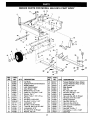
REPAIR
PARTS
11
FOR MODEL
13
486.24516
CART
BODY
14
/
11
1
I
14
6
9
\
10
\
@
REF.
NO.
1
2
3
4
5
6
7
8
9
10
11
12
13
14
15
16
17
18
PART
NO.
23985
62458
23507
24497
23488
46272
43093
43601
44678
43014
43866
1509-69
43177
43178
43814
43086
43083
43088
QTY.
2
1
1
1
1
2
2
4
2
2
9
2
13
13
14
14
14
2
REF.
NO,
DESCRIPTION
Cart Body
Tailgate Reinforcement Bracket
Wheel Support
Latch Stand Bracket
Axle, Wheel 1" Dia.
Wheel w/Tire, 15 x 6.00
Cotter Pin, 118" Dia. x 1-1/2"
Washer, Flat 1"
Spacer Tube, 1-1/4" x 2" Lg.
Hub Cap
Hex Bolt, 1/4-20 x 5/8"
Hex Bolt, 1/4-20 x 1-3/4"
Lockwasher, 1/4"
Hex Nut, 1/4-20 Thread
Truss Hd. Bolt, 5/16-18 x 3/4"
Lockwasher, 5/16"
Hex Nut, 5/16-18 Thread
Washer, Flat 1/4"
19
20
21
22
23
24
25
26
27
28
29
30
31
32
33
34
35
36
25
PART
NO.
63917
63155
24614
23475
43884
43343
43087
43003
43082
47407
47408
43574
43064
46980
23838
43661
43572
24604
QT¥
1
1
1
1
1
1
2
5
5
1
1
3
1
2
2
2
4
1
DESCRIPTION
Tongue Weldment Ass'y. (Rear)
Tongue Weldment Ass'y. (Front)
Latch Lock Lever
Hitch Bracket
Hitch Pin
Pin, Hair Cotter 1/8"
Hex Bolt, 3/8-16 x 1-1/4"
Lockwasher, 3/8"
Hex Lock Nut, 3/8-16 Thread
Hex Bolt, 5/16-18 x 3-3/4"
Spring, Extension
Hex Bolt, 3/8-16 x 3"
Hex Lock Nut, 5/16-18
Hex Nut, 5/16-18 (SEMS)
Door Support
Hex Bolt, 1/4-20 x 1"
Flat Washer, 1-1/2" x 11/32"
Skid Plate
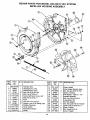
REPAIR PAFITS FOR I_ODEL 486.24516
CHIPPER VAC SYSTEM
72
4
\
39
66
6O
61
38 37
59
28
13
\
2O
70
21
14
3O
\
53
9
7
ADAPTER
8.
4O
#62468
44
_4o
.ft54
12_
45
42_
&-13
26
TRACTOR
16
REPAIR
PARTS
REF,
NO.
PART
NO.
QTY.
1
2
3
24080
24078
63226
1
2
1
4
5
6
7
8
9
43182
43063
43085
43086
43064
63375
14
2
4
16
15
1
10
11
12
13
14
15
16
17
18
19
20
21
22
23
24
25
26
27
28
29
3O
31
32
33
34
35
36
781-0635
1
728-3001
3
43012
8
43013
10
7520155481 1
222261
1
63227
1
46420
1
43792
1
43793
2
24608
2
24609
1
24610
2
63918
1
43882
43910
23842
46480
44790
43790
44849
44850
23540
43866
43661
43088
1509-90
8
8
4
1
1
1
2
2
1
3O
2
59
2
FOR MODEL
486.24516
DESCRIPTION
CHIPPER
REF.
NO.
PART
NO.
QTY.
37
38
39
40
41
42
43
44
45
46
47
48
49
50
51
52
53
43178
43177
24582
1543-69
43351
43262
43352
43081
43830
23560
43080
23825
23826
23827
47630
712-0421
44
38
3
9
1
1
1
15
1
1
2
1
1
1
4
3
1
54
62468
55
56
57
58
59
60
61
62
63
64
65
66
67
68
69
70
71
72
73
44419
47640
43364
43662
23476
47642
47641
43070
43082
24612
24613
47810
63376
735-0249
781-0633
47810
24098
731-1617
381-0068
47813
Engine Base
Brace, Housing
Hose Hanger Bracket Ass'y.
(Ref. item #16 on page 22.)
Bolt, Hex 5/16-18 x 3/4"
Bolt, Hex 5/16-18 x 1"
Bolt, Hex 5/16-18 x 1-1/2"
Lockwasher, 5/16" Spring Type
Nut, Hex Lock 5/16-18
Assembly, Hose Adapter (Nozzle)
'Includes items 10 and 11))
Bracket, Switch (Actuator)
Rivet, Pop 5/32"
Bolt, Hex 1/4-20 x 3/4"
Nut, Hex Lock 1/4-20 Thd.
Engine, 8 HP Tecumseh
I_eflector, Muffler
Hose Hanger Rod Ass'y.
Elbow
Hose (6" x 84")
Hose Clamp 6"
Side Panel Cart Extension
Front Panel Cart Extension
Side Bracket ("Z")
Hard Top Assembly
(Includes 24,25,26,27)
Rivet, 3/16"
Washer, Flat 3/16"
Boot Mounting Strap
Hard top Boot
Poly Rear Door
Strap, Tarp 25"
"S" Hook, #32
Strap, Tarp (Less Hooks)
Hitch Plate
Bolt, Hex 1/4-20 x 5/8"
Bolt, Hex 1/4-20 x 1"
Washer, 1/4" STD
Bolt, Hex 1/4-20 x 1-1/4"
27
2
1
2
2
2
1
1
4
4'.
1
1
6
1
1
1
3
1
1
1
1
VAC SYSTEM
DESCRIPTION
Nut, Hex 1/4-20
Lockwasher, Spring 1/4"
Hinge, Poly Top
Washer, Nylon 21/64"
Bolt, Hex 1/2-13 x 1-1/4"
Nut, Hex Lock 1/2-13
Washer, Flat 7/16"
Washer, 5/16" STD
Adapter, Deck
Bracket, Deck Adapter
Bolt, Carr. 5/16" x 3/4"
Mounting Strap
Angle Bracket
Mounting Bracket
Screw, Self Tap 5/16-18 x 3/4"
Knob (See also Item #8, Page 28)
Impeller Housing Assembly
(See page 28)
Deck Adapter Kit (Includes parts in
box shown on page 26)
Eyebolt, 1/4"
Handle, Dump
Bolt, Truss Hd. #10-32 x 5/8"
Nut, Hex #10-32 (SEMS)
Rod, Tie
Rod, Prop (RH)
Rod, Prop (LH)
Washer, Flat 3/8"
Nut, Hex Lock 3/8-16
Latch, Door (RH)
Latch, Door (LH)
Nut, Nylock, 5/16-18
Assy., Chute, Chipper (Upper)
Flap, Chute
Strap, Flap
Nut, Hex Lock 5/16"
Bracket, Chute Reinforcement
Tamper, Plug
Chute Assembly
Owner's Manual
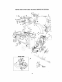
REPAIR
PARTS FOR MODEL 486.24516
VAC SYSTEM
IMPELLER
HOUSING ASSEMBLY
Q
I
REF,
NO.
PART
NO.
1
2
3
4
5
6
7
8
9
10
11
12
13
14
_29-0241A!
63933
24633
43182
710-0772
710-1268
43063
712-0421
43064
43086
Z19-0330A
725-1700
725-3166
726-0272
QTY. DESCRIPTION
REF
NO.
PART
NO.
QTY.
DESCRIPTION
1
1
1
12
3
2
3
Harness, Wire
Housing Ass'y. Inner
Housing Ass'y. Outer
Bolt, Hex 5/16-18 x 3/4"
Bolt, Hex 5/16-24 x 2"
Screw, Self Tap #10-16 x 3/8"
Bolt, Hex 5/16-18 x 1"
15
16
17
18
19
20
21
731-1613
63226
712-3046
24606
736-0247
63924
710-1273
1
1
3
1
1
1
1
Cover, Switch
Hose Hanger Bracket. Ass'y.
Nut, Hex Jam 5116o18Thd.
Spacer, Housing
Flat Washer, 13/32" x 1-1/4"
Impeller Assembly
Bolt, Hex 3/8-24 x 2-3/4"
3
12
19
1
1
1
1
Knob
Nut, Hex Lock 5/16-18
Washer, Lock 5/16" Spring Type
Adapter, Mounting
Cover, Switch
Snap Mount Switch
Clamp
22
23
24
25
26
27
28
43003
i
629-0923 _
44738
710-1054
742-0544
47810
781-0627
1
1
4
4
2
2
1
Lockwasher, 3/8"
Harness Adapter
Nut, Hex Lock 5/16-24 "Unitork"
Screw, Flat Hd. 5/16-24 x 1"
Blade, Chipper
Nut, Nylock 5/16-18
Cover, Chipper
28
i
(D
II
I
I
10°
E=CD
o
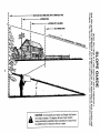
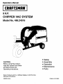
&
CAUTION:
Do not operate your tractor and Chipper
Vac System
on a slope in excess of 10 degrees. Be sure of your tractor's
towing and braking capabilities before operating on a slope. Avoid
any sudden turns or maneuvers while on a siope.
3_
m 0
," 91
m '-t
.--Q.
NOTES
30
NOTES
31
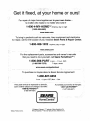
Get it fixed,
your home or ours!
For repair of major brand appliances in your own home...
no matter who made it, no matter who sold it!
1-800-4-MY-HOME
sMAnytime,
day or night
(1-800-469-4663)
www.sears.com
To bring in products such as vacuums, lawn equipment and electronics
for repair, call for the location of your nearest Sears Parts & Repair Center.
1-800-488-1222
Anytime, day or night
www.sears,com
For the replacement parts, accessories and owner's manuals
that you need to do-it-yourself, call Sears PartsDirect sM!
1-800-366-PART
6 a.m. - 11 p.m. CST,
(1-800-366-7278)
7 days a week
www.sears.condpartsdirect
To purchase or inquire about a Sears Service Agreement:
1-800-827-6655
7 a.m. - 5 p.m. CST, Mon. - Sat.
Para pedir servicio de reparaci6n a domicilio,
y para ordenar piezas con entrega a domicUio:
1-888"SU'HOGAR
Au Canada
pour service en fran_ais:
1-877-LE-FOYER _
sM
(1-877-533-6937)
(1-888-784-6427)
I HomeCentral"
SEARS }
® Registered
O Sears,
Roebuck
and Co.
® Marca
Trademark
Regist rada / r_
/
,rM
MarCa
Trademark
de F_brica
of Sears,
de Sears,
Roebuck
Roebuck
and
and
Co.
Co.