1
Vipersat CDM-570/570L
Satellite Network Modem Router
User Guide
Part Number MN/22125 Revision 0
Vipersat CDM-570/570L
Version 1.5.x
User Guide
Part number MN/22125
Document Revision 0
Firmware Version 1.5.x
January 16, 2008
COMTECH EF DATA
VIPERSAT Network Products Group
3215 Skyway Court
Fremont, CA 94539
USA
Phone: (510) 252-1462
Fax: (510) 252-1695
www.comtechefdata.com
Part Number MN/22125
Manual Revision 0
Firmware Version 1.5.x
©2008 by Comtech EF Data, Inc. All rights reserved. No part of this manual may
be copied or reproduced without prior written permission of Comtech EF Data,
Inc.
Comtech reserves the right to revise this publication at any time without
obligation to provide notification of such revision. Comtech periodically revises
and improves its products and, therefore, the information in this document is
subject to change without prior notice. Comtech makes no warranty of any kind
with regard to this material, including but not limited to the implied warranties of
mechantability and fitness for a particular purpose. No responsibility for any
errors or omissions that may pertain to the material herein is assumed.
Comtech makes no commitment to update nor to keep current the information
contained in this document.
All products, names, and services are trademarks or registered trademarks of
their respective companies.
Printed in the United States of America
Document Revision Status
Document
Revision
Date
Revision 0
1/16/08
Description
Affected Pages
Revisions for firmware version 1.5.4.
Document part number changed from
22125 to MN/22125.
N/A
{ This Page is Intentionally Blank }
Table of Contents
General
How to Use This Manual . . . . . . . . . . . 1-1
Manual Organization . . . . . . . . . . . . 1-1
Chapter 1 — General . . . . . . . . . 1-1
Chapter 2 — Quick Start Configuration 1-1
Chapter 3 — Using the Command Line
Interface (CLI) . . . . . . . . . . . . 1-2
Appendix A — Network Addressing . . 1-2
Appendix B — Automatic Switching . . 1-2
Appendix C — Dynamic Power Control1-2
Appendix D — Network Migration . . . 1-2
Appendix E — Glossary . . . . . . . . 1-2
Conventions and References . . . . . . . . 1-2
Product Description . . . . . . . . . . . . . . 1-4
Introduction . . . . . . . . . . . . . . . 1-4
Modem Features. . . . . . . . . . . . . 1-4
Router Features . . . . . . . . . . . . . 1-4
Network and Bandwidth Management. . 1-5
Dynamic SCPC (dSCPC) . . . . . . . . 1-5
Turbo Product Coding . . . . . . . . . . 1-6
Header Compression . . . . . . . . . . 1-6
Payload Compression . . . . . . . . . . 1-6
Quality of Service . . . . . . . . . . . . 1-6
Data Encryption . . . . . . . . . . . . . 1-6
New in this Release . . . . . . . . . . . . . 1-6
1.5.4 Release . . . . . . . . . . . . . . 1-7
New DPC (Dynamic Power Control)
Enhancements . . . . . . . . . . . . 1-7
STDMA Power Hunt . . . . . . . . . . 1-7
Hitless Switching. . . . . . . . . . . . 1-7
VMS Registration and Managing Address
1-7
UDP Port Base Address . . . . . . . . 1-7
Auto Home State Failsafe . . . . . . . 1-8
SOTM (Satellite On The Move) . . . . 1-8
Dynamic Routing . . . . . . . . . . . 1-8
Dynamic QoS Rules . . . . . . . . . . 1-8
Customer Support . . . . . . . . . . . . . . . 1-9
Contact Information . . . . . . . . . . . 1-9
Return Material Authorization . . . . . . 1-9
Reader Comments / Corrections . . . . 1-9
Quick Start Configuration
Introduction . . . . . . . . . . . . . . . . . .
Initial Configuration . . . . . . . . . . . . . .
2-1
2-2
Terminal Connection . . . . . . . . . . 2-2
Network Role . . . . . . . . . . . . . . . . 2-3
Setting Vipersat CDM-570/570L Operating
Parameters. . . . . . . . . . . . . . . . . 2-3
Set the Feature Configuration . . . . . . 2-3
Set the IP Address . . . . . . . . . . . 2-6
Configure the Route Table . . . . . . . 2-7
Routing in a Vipersat Network. . . . . 2-7
Creating the Routes . . . . . . . . . . 2-8
Set the Satellite Modem Configuration 2-10
Set the Vipersat Configuration . . . . 2-10
Using the Command Line Interface
(CLI)
General . . . . . . . . . . . . . . . . . . . . . 3-1
Common Screen Commands . . . . . . . . 3-2
Save Parameters to Permanent Storage 3-2
Exit . . . . . . . . . . . . . . . . . . . 3-2
Telnet Logout . . . . . . . . . . . . . . 3-2
Menu Descriptions . . . . . . . . . . . . . . . 3-3
Main menu . . . . . . . . . . . . . . . . . 3-3
Administration . . . . . . . . . . . . . . 3-3
Feature Configuration . . . . . . . . . . . . 3-5
Vipersat Feature Codes . . . . . . . . . 3-5
Vipersat Management . . . . . . . . . . 3-6
Vipersat STDMA . . . . . . . . . . . . 3-6
Vipersat Auto Switching . . . . . . . . . 3-6
Vipersat File Streamer. . . . . . . . . . 3-7
Vipersat Configuration . . . . . . . . . . . . . 3-8
STDMA Mode . . . . . . . . . . . . . . . . 3-8
STDMA . . . . . . . . . . . . . . . . . 3-9
STDMA Tx Rate . . . . . . . . . . . . . 3-9
Hub Type . . . . . . . . . . . . . . . 3-10
1 – Fixed . . . . . . . . . . . . . . 3-10
2 – Dynamic Slot . . . . . . . . . . 3-11
3 – Dynamic Cycle . . . . . . . . . 3-11
4 – GIR . . . . . . . . . . . . . . . 3-11
5 – Entry Channel . . . . . . . . . . 3-12
Group ID. . . . . . . . . . . . . . . . 3-12
STDMA Power Hunt. . . . . . . . . . 3-13
Low Data Rate Fast Acquisition . . . . 3-13
Burstmap Multicast IP . . . . . . . . . 3-14
Outbound IP . . . . . . . . . . . . . . 3-14
Cycles Per Burst Map . . . . . . . . . 3-15
Slot Guardband . . . . . . . . . . . . 3-15
i
Slot Preamble Length . . . . . . . . . 3-16
Slot Data Length . . . . . . . . . . . . 3-16
Slot Cycle Length . . . . . . . . . . . 3-17
Slot Start in Cycle . . . . . . . . . . . 3-17
Set Remotes . . . . . . . . . . . . . . 3-17
Adding a Remote to the STDMA Group .
3-18
Base . . . . . . . . . . . . . . . . . 3-19
Remote Count . . . . . . . . . . . . 3-19
Set Remote Policies . . . . . . . . . 3-20
Delete Remote . . . . . . . . . . . . 3-22
Enable/Disable Remote . . . . . . . 3-22
View Remote(s) . . . . . . . . . . . 3-23
Remove Timeout . . . . . . . . . . 3-23
Remove Retry Timeout . . . . . . . 3-24
STDMA Statistics . . . . . . . . . . . 3-24
Show Hub Statistics . . . . . . . . . . 3-25
STDMA/SCPC Automatic Switching. . . . 3-27
Auto Switching . . . . . . . . . . . . . 3-28
Current WAN Transmit Mode . . . . . 3-28
Voice & Video Application Switching . 3-29
Voice Switch Detection . . . . . . . 3-29
Video Switch Detection . . . . . . . 3-29
ToS Switch Detection . . . . . . . . . 3-30
QoS Switch Detection . . . . . . . . . 3-31
Enable Quality of Service (QoS) Feature
3-31
Configure QoS Rules . . . . . . . . 3-31
Configure QoS Rules Based Switching .
3-33
Enable QoS Switch Detection Feature .
3-33
Load Switching . . . . . . . . . . . . 3-33
STDMA Slot Capacity . . . . . . . . . 3-34
STDMA Switch Delay . . . . . . . . . 3-34
Percent Allocation . . . . . . . . . . . 3-35
SCPC Step Up Threshold . . . . . . . 3-35
SCPC Step Down Threshold . . . . . 3-36
SCPC Step Delay . . . . . . . . . . . 3-36
SCPC Step Up Excess . . . . . . . . 3-37
Keep Alive Timer for Carrier Inhibit . . 3-37
Time for Carrier Inhibit . . . . . . . . . 3-38
ToS Switching Parameters. . . . . . . 3-38
ToS Switching Entry . . . . . . . . . 3-39
Delete . . . . . . . . . . . . . . . . 3-40
View . . . . . . . . . . . . . . . . . 3-40
Hitless Switching Parameters . . . . . 3-41
Delay for Mod . . . . . . . . . . . . 3-41
Delay for Demod . . . . . . . . . . . 3-42
ii
LockTimes. . . . . . . . . . . . . . 3-42
Apply Delay Values . . . . . . . . . 3-42
SOTM Update . . . . . . . . . . . . . 3-42
SOTM Mode. . . . . . . . . . . . . . 3-43
Unit Role . . . . . . . . . . . . . . . . . 3-43
Expansion Unit . . . . . . . . . . . . . . 3-44
Network ID . . . . . . . . . . . . . . . . 3-44
Unit Name . . . . . . . . . . . . . . . . . 3-45
Receive Multicast Address . . . . . . . . 3-45
Managing IP Address . . . . . . . . . . . 3-46
Primary Heart Beat . . . . . . . . . . . . 3-47
Home State Revert . . . . . . . . . . . . 3-47
Dynamic Power Control Configuration . . 3-48
DPC Enabled . . . . . . . . . . . . . 3-49
Calibrated Data Rate . . . . . . . . . 3-49
Nominal Power Level . . . . . . . . . 3-50
Max Power . . . . . . . . . . . . . . 3-50
Min Power . . . . . . . . . . . . . . . 3-50
Target EbNo . . . . . . . . . . . . . . 3-51
Target Range . . . . . . . . . . . . . 3-51
Speed Up EbNo . . . . . . . . . . . . 3-51
Target DPC Address . . . . . . . . . 3-52
BaseLine Power . . . . . . . . . . . . 3-53
DPC Offset . . . . . . . . . . . . . . 3-53
SOTM Offset . . . . . . . . . . . . . 3-53
Set Home State Parameters . . . . . . . 3-53
Set Current Configuration as Home State. .
3-54
Force Modem to Home State . . . . . 3-55
STDMA State . . . . . . . . . . . . . 3-55
Transmit Frequency . . . . . . . . . . 3-55
Transmit Data Rate . . . . . . . . . . 3-55
Transmit FEC Type . . . . . . . . . . 3-56
Transmit Coding Rate . . . . . . . . . 3-56
Transmit Modulation Type . . . . . . . 3-57
Transmit Power Level . . . . . . . . . 3-57
Transmit Enable . . . . . . . . . . . . 3-57
Receive Frequency . . . . . . . . . . 3-57
Receive Data Rate . . . . . . . . . . 3-58
Receive FEC Type . . . . . . . . . . 3-58
Receive Coding Rate . . . . . . . . . 3-59
Receive Modulation Type . . . . . . . 3-59
Vipersat Summary . . . . . . . . . . . . 3-59
Vipersat Migration . . . . . . . . . . . . . 3-61
UDP Port Base Address . . . . . . . . . 3-61
Network Addressing
Introduction . . . . . . . . . . . . . . . . . .
The OSI Reference Model . . . . . . . . . .
A-1
A-2
Vipersat CDM-570/570L U s e r G u i d e
Layers 1 – 3 . . . . . . . . . . . . . . .
Binary Math . . . . . . . . . . . . . . . . .
IP Addressing . . . . . . . . . . . . . . . .
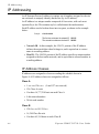
IP Address Classes . . . . . . . . . . .
Class A . . . . . . . . . . . . . .
Class B . . . . . . . . . . . . . .
Class C . . . . . . . . . . . . . .
Class D . . . . . . . . . . . . . .
Class E . . . . . . . . . . . . . .
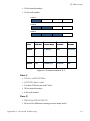
Private Network IP Addresses . . . .
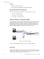
Network Address Translation (NAT) .
Subnets . . . . . . . . . . . . . . . . .
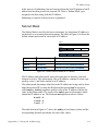
Subnet Mask. . . . . . . . . . . . . . .
Network Segments . . . . . . . . . . .
Default Gateways . . . . . . . . . . . .
MAC Addresses . . . . . . . . . . . . .
.
.
.
.
.
.
.
.
.
.
.
.
.
.
.
.
.A-2
A-4
A-6
.A-6
.A-6
.A-6
.A-7
.A-7
.A-8
.A-8
.A-8
.A-8
.A-9
A-10
A-11
A-11
Automatic Switching
General . . . . . . . . . . . . . . . . . . . . B-1
Bandwidth Allocation and Load Switching. .B-2
Load Switching . . . . . . . . . . . . . . . . B-3
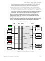
Bandwidth Allocation and Load Switching by
the STDMA Controller . . . . . . . . .B-3
Load Switching Process . . . . . . . . .B-6
Load Switching by a Remote . . . . . .B-7
Determining Need-for-Change. . . . . .B-8
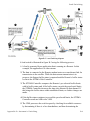
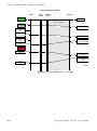
Load Switch Example . . . . . . . . . . . .B-8
Reduced Data Flow in Switched Mode
(SCPC) . . . . . . . . . . . . . . . B-10
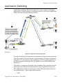
Application Switching . . . . . . . . . . . . . B-11
Type of Service (ToS) Switching . . . . . . . B-13
Entry Channel Mode (ECM) Switching . . . . B-14
Fail-Safe Operation . . . . . . . . . . . . B-14
Dynamic Power Control
Description . . . . . . . . . . . . . . . . . . C-3
Higher Order Modulation BER Waterfall
Mapping . . . . . . . . . . . . . . . C-4
Delta Rain Fade Power CompensationC-4
Adjustment for Data Rate . . . . . . . C-5
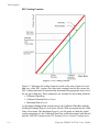
DPC Scaling Function . . . . . . . . . C-6
Network Migration
General . . . . . . . . . . . . . . . . . . . . D-1
Firmware Upgrade . . . . . . . . . . . . . . D-3
Upgrade Overview . . . . . . . . . . . . . D-3
Required Support Utilities and Firmware D-3
Basic Steps . . . . . . . . . . . . . . . D-3
Migration Procedure . . . . . . . . . . . . D-4
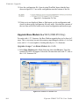
Configure Upgrade Image. . . . . . . . D-4
Getting Information with VLOAD . . . . D-5
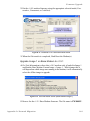
Upgrade Router to v1.5.3 . . . . . . . . D-7
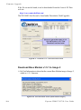
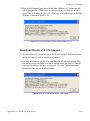
Save and Reboot to Latest . . . . . . . D-9
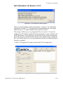
Get Information for Router v1.5.3 . . . D-11
Upgrade Base Modem to v1.5.1 (CDM-570
Only). . . . . . . . . . . . . . . . . D-12
Upgrade Image 1 on Base Modem to
v1.4.5 . . . . . . . . . . . . . . . D-12
Upgrade Image 1 on Base Modem to
v1.5.1 . . . . . . . . . . . . . . . D-13
Download Base Modem v1.5.1 to Image 2 .
D-14
Download Router v1.5.3 to Image 2. . D-15
Completing Migration . . . . . . . . . . . D-16
Picking Up Straggler/Offline Remotes. D-16
Setting v1.5.2 Compatibility in Hub Modems
D-16
Glossary
Introduction . . . . . . . . . . . . . . . . . . C-1
iii
{ This Page is Intentionally Blank }
iv
Vipersat CDM-570/570L U s e r G u i d e
List of Figures
Chapter 2 Figures
Figure 2-1 Main Menu screen. . . . . . . . . . . . . . 2-4
Figure 2-2 Administration screen . . . . . . . . . . . 2-4
Figure 2-3 Feature Configuration screen . . . . . 2-5
Figure 2-4 FAST Feature Code dialog . . . . . . . 2-5
Figure 2-5 Working Mode dialog . . . . . . . . . . . 2-6
Figure 2-6 Ethernet Interface screen . . . . . . . . 2-7
Figure 2-7 Configuring the Route Table screen 2-9
Figure 2-8 Tx Configuration screen . . . . . . . . 2-10
Figure 2-9 Vipersat Configuration screen (Hub). .
2-11
Chapter 3 Figures
Figure 3-1 Main Menu screen. . . . . . . . . . . . . . 3-3
Figure 3-2 Administration screen . . . . . . . . . . . 3-4
Figure 3-3 Working Mode dialog . . . . . . . . . . . 3-4
Figure 3-4 Feature Configuration screen . . . . . 3-5
Figure 3-5 FAST Feature Code dialog . . . . . . . 3-6
Figure 3-6 Vipersat Configuration screen (Hub)3-8
Figure 3-7 STDMA screen (Hub, Dynamic Cycle
type). . . . . . . . . . . . . . . . . . . . . . . . . . . . 3-9
Figure 3-8 STDMA screen (Remote) . . . . . . . . 3-9
Figure 3-9 Hub Type prompt . . . . . . . . . . . . . 3-10
Figure 3-10 Group ID prompt . . . . . . . . . . . . . 3-13
Figure 3-11 Burstmap Multicast IP prompt . . . 3-14
Figure 3-12 Outbound IP prompt . . . . . . . . . . 3-14
Figure 3-13 Cycles per Burst Map prompt . . . 3-15
Figure 3-14 Slot Guardband prompt. . . . . . . . 3-15
Figure 3-15 Slot Preamble Length prompt . . . 3-16
Figure 3-16 Slot Data Length (Nominal). . . . . 3-17
Figure 3-17 STDMA Remotes Menu screen . 3-18
Figure 3-18 Adding a Remote to the STDMA group
3-18
Figure 3-19 Modifying Remote Display Base . 3-19
Figure 3-20 STDMA Remote Policies screen (GIR
Hub) . . . . . . . . . . . . . . . . . . . . . . . . . . . 3-20
Figure 3-21 GIR Remote Policies prompt. . . . 3-20
Figure 3-22 Entry Channel Switch Rates screen .
3-21
Figure 3-23 Remote SCPC Data Rate and Switch
Type prompt. . . . . . . . . . . . . . . . . . . . . 3-21
Figure 3-24 Global SCPC Data Rate prompt . 3-22
Figure 3-25 Global Switch Type prompt . . . . .3-22
Figure 3-26 Delete Remote prompt . . . . . . . .3-22
Figure 3-27 Enable/Disable Remote prompt .3-22
Figure 3-28 View Remote(s) screen . . . . . . . .3-23
Figure 3-29 Remove Timeout prompt . . . . . . .3-23
Figure 3-30 Remove Retry Timeout prompt . .3-24
Figure 3-31 STDMA Statistics screen (Hub). .3-25
Figure 3-32 STDMA Statistics screen (Remote). .
3-25
Figure 3-33 Hub Statistics screen. . . . . . . . . .3-26
Figure 3-34 STDMA/SCPC Auto Switching screen
(Hub) . . . . . . . . . . . . . . . . . . . . . . . . . .3-27
Figure 3-35 STDMA/SCPC Auto Switching screen
(Remote) . . . . . . . . . . . . . . . . . . . . . . .3-28
Figure 3-36 QoS Configuration screen . . . . . .3-32
Figure 3-37 QoS Rules Configuration screen .3-32
Figure 3-38 QoS Rules Based Switching screen .
3-33
Figure 3-39 STDMA Slot Capacity prompt . . .3-34
Figure 3-40 STDMA Switch Delay prompt . . .3-35
Figure 3-41 Percent Allocation prompt . . . . . .3-35
Figure 3-42 SCPC Step Up Threshold prompt3-36
Figure 3-43 SCPC Step Down Threshold prompt.
3-36
Figure 3-44 SCPC Step Delay prompt . . . . . .3-37
Figure 3-45 SCPC Step Up Excess prompt . .3-37
Figure 3-46 Keep Alive Timer for Carrier Inhibit
prompt . . . . . . . . . . . . . . . . . . . . . . . . .3-38
Figure 3-47 Time for Carrier Inhibit prompt . .3-38
Figure 3-48 ToS Switching Control screen . . .3-39
Figure 3-49 ToS Switching Entry dialog . . . . .3-39
Figure 3-50 ToS Delete prompt . . . . . . . . . . .3-40
Figure 3-51 ToS View screen . . . . . . . . . . . . .3-41
Figure 3-52 Hitless Switching screen . . . . . . .3-41
Figure 3-53 Set LockTime prompt . . . . . . . . .3-42
Figure 3-54 VMS Routes in Route Table . . . .3-43
Figure 3-55 Unit Role prompt . . . . . . . . . . . . .3-44
Figure 3-56 Expansion Unit prompt . . . . . . . .3-44
Figure 3-57 Network ID prompt . . . . . . . . . . .3-45
Figure 3-58 Unit Name prompt . . . . . . . . . . . .3-45
Figure 3-59 Receive Multicast IP Address prompt
3-46
Figure 3-60 Managing IP address menu . . . .3-46
Figure 3-61 DPC Configuration screen (STDMA
mode) . . . . . . . . . . . . . . . . . . . . . . . . . .3-48
v
Figure 3-62 DPC Configuration screen (SCPC
mode). . . . . . . . . . . . . . . . . . . . . . . . . . 3-49
Figure 3-63 Maximum Power Level prompt (CDM570L) . . . . . . . . . . . . . . . . . . . . . . . . . . 3-50
Figure 3-64 Minimum Power Level prompt (CDM570L) . . . . . . . . . . . . . . . . . . . . . . . . . . 3-50
Figure 3-65 Target EbNo prompt . . . . . . . . . . 3-51
Figure 3-66 Target Range prompt . . . . . . . . . 3-51
Figure 3-67 Speed Up EbNo prompt . . . . . . . 3-52
Figure 3-68 Target DPC Address prompt. . . . 3-52
Figure 3-69 Home State Configuration screen3-54
Figure 3-70 Force Modem to Home State warning
3-55
Figure 3-71 Transmit Frequency prompt . . . . 3-55
Figure 3-72 Transmit Data Rate prompt. . . . . 3-56
Figure 3-73 Transmit FEC Type prompt. . . . . 3-56
Figure 3-74 Transmit Coding Rate prompt . . . 3-56
Figure 3-75 Transmit Modulation Type prompt3-57
Figure 3-76 Transmit Power Level prompt . . . 3-57
Figure 3-77 Receive Frequency prompt . . . . . 3-58
Figure 3-78 Receive Data Rate prompt . . . . . 3-58
Figure 3-79 Receive FEC Type prompt . . . . . 3-58
Figure 3-80 Receive Coding Rate prompt . . . 3-59
Figure 3-81 Receive Modulation Type prompt 3-59
Figure 3-82 Vipersat Summary screen (Hub). 3-60
Figure 3-83 Vipersat Migration prompt . . . . . . 3-61
Figure 3-84 UDP Port Base Address prompt . 3-61
Appendix A Figures
Figure A-1 The Seven OSI Protocol Layers . . .A-2
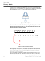
Figure A-2 Bits and Bytes. . . . . . . . . . . . . . . . .A-4
Figure A-3 Binary to Decimal Conversion . . . .A-4
Figure A-4 IP Address Classes A, B, C . . . . . .A-7
Figure A-5 NAT Router Example . . . . . . . . . . .A-8
Figure A-6 Default Subnet Masks for IP Classes .
A-9
Figure A-7 ANDing an IP address and a subnet
mask . . . . . . . . . . . . . . . . . . . . . . . . . .A-10
Figure A-8 Network Segments . . . . . . . . . . . .A-10
Figure A-9 Router as Default Gateway. . . . . .A-11
Figure A-10 Network Node MAC Addresses .A-12
Appendix B Figures
Figure B-2 Auto Switching menu (Remote) . . B-7
Figure B-3 Load Switching diagram . . . . . . . . B-9
Figure B-4 Application Switching diagram . . B-11
Figure B-5 ECM Switch Recovery: < 3 minutes . .
B-15
Figure B-6 ECM Switch Recovery: > 3 minutes . .
B-16
Appendix C Figures
Figure C-1 DPC Scaling Function. . . . . . . . . . C-6
Appendix D Figures
Figure D-1 Firmware Migration Stages—CDM-570
D-4
Figure D-2 Main Menu, Telnet . . . . . . . . . . . . D-5
Figure D-3 Operations and Maintenance MenuD-5
Figure D-4 Initial Vload screen . . . . . . . . . . . . D-6
Figure D-5 Add All dialog . . . . . . . . . . . . . . . . D-6
Figure D-6 Get Information for IP Address . . . D-7
Figure D-7 Put Application screen (Consecutive
Load) . . . . . . . . . . . . . . . . . . . . . . . . . . D-8
Figure D-8 Progress Status, Put Application . D-9
Figure D-9 Hard Reset screen . . . . . . . . . . . D-10
Figure D-10 Progress Status, Put CompletionD-10
Figure D-11 Unit Information screen (Router) D-11
Figure D-12 Select Configuration screen . . . D-11
Figure D-13 Configuration File Text . . . . . . . D-12
Figure D-14 Browse for Firmware File . . . . . D-12
Figure D-15 Download v1.4.5 and Hard Reset
screen . . . . . . . . . . . . . . . . . . . . . . . . D-13
Figure D-16 Unit Information screen (Base Modem
Image 1) . . . . . . . . . . . . . . . . . . . . . . . D-13
Figure D-17 Download v1.5.1 and Hard Reset
screen . . . . . . . . . . . . . . . . . . . . . . . . D-14
Figure D-18 Unit Information screen (Base Modem
Image 2) . . . . . . . . . . . . . . . . . . . . . . . D-14
Figure D-19 Unit Information screen (Base Modem
v1.5.1) . . . . . . . . . . . . . . . . . . . . . . . . D-15
Figure D-20 Unit Information screen (final status)
D-15
Figure D-21 Main Menu screen, CLI. . . . . . . D-16
Figure D-22 Vipersat Configuration screen . D-17
Figure D-23 Vipersat Migration prompt. . . . . D-17
Figure B-1 Auto Switching menu (Hub) . . . . . .B-5
vi
Vipersat CDM-570/570L User Guide
List of Tables
Chapter 2 Tables
Table 2-1 CDM-570/570L Network Roles and
Functions . . . . . . . . . . . . . . . . . . . . . . . . 2-3
Table 2-2 Vipersat Feature Configuration . . . . 2-6
Appendix B Tables
Table B-1 STDMA ACK Message . . . . . . . . . .B-3
Appendix C Tables
Table C-1 Dynamic Power Control ParametersC-3
vii
{ This Page is Intentionally Blank }
viii
Vipersat CDM-570/570L User Guide
CHAPTER
GENERAL
How to Use This Manual
This manual documents the enhanced Vipersat features and functions of the
CDM-570/570L Satellite Network Modem Router, and guides the user in how
to configure this product for use in a Vipersat network. The material covered
addresses only those areas specific to a CDM-570/570L running in Vipersat
mode, and complements the universal features and functions described in the
CDM-570/570L Installation and Operation Manual.
Earth station engineers, technicians, and operators responsible for the configuration and maintenance of the CDM-570/570L are the intended audience for this
document.
Manual Organization
This User Guide is organized into the following sections:
Chapter 1 — General
Contains CDM-570/570L product description, customer support information,
and manual conventions and references.
Chapter 2 — Quick Start Configuration
Covers the initial basic steps that are necessary for configuring the CDM-570/
570L from a factory default state to a functional network element.
C h ap t e r 1 - G e n e r a l
1-1
How to Use This Manual
Chapter 3 — Using the Command Line Interface (CLI)
Describes the use of the CLI for configuring and monitoring the CDM-570/
570L in a Vipersat network. Each CLI screen is presented along with a detailed
description and related commands.
Appendix A — Network Addressing
Supplemental reference information on binary math and network addressing to
assist with integrating the CDM-570/570L into a Vipersat network.
Appendix B — Automatic Switching
Supplemental reference information on the Vipersat feature that provides Load
switching (response to network traffic load), Application switching (response to
traffic type) functions, and Entry Channel Mode switching functions.
Appendix C — Dynamic Power Control
A description of Vipersat’s DPC and its relationship to a CDM-570/570L
configuration.
Appendix D — Network Migration
Procedural instructions on upgrading a Vipersat network of CDM-570/CDD56X series equipment to firmware version 1.5.3.
Appendix E — Glossary
A glossary of terms that pertain to Vipersat satellite network technology.
Conventions and References
The following conventions are utilized in this manual to assist the reader:
NOTE
Note: Provides important information relevant to the accompanying
text.
Tip: Provides complementary information that facilitates the
associated actions or instructions.
Caution: Explanatory text that notifies the reader of possible
consequences of an action.
1-2
Vipersat CDM-570/570L User Guide
How to Use This Manual
The following documents are referenced in this manual, and provide supplementary information for the reader:
• CDM-570/570L Modem Installation and Operation Manual (Part Number
MN/CDM570L.IOM)
• CDD-564L Quad Demodulator Installation and Operation Manual (Part
Number MN/CDD564L.IOM)
• Vipersat CDD-56X Series User Guide (Part Number MN/22137)
• Vipersat Management System User Guide (Part Number MN/22156)
• Vload Utility User Guide (Part Number MN/22117)
C h ap t e r 1 - G e n e r a l
1-3
Product Description
Product Description
Introduction
The Vipersat CDM-570 and CDM-570L (L-band) Satellite Network Modem
Routers offer state of the art performance and reliability in a sophisticated and
cost-effective 1RU package. The CDM-570/570L integrates router functionality
into the modem, completely eliminating external serial port cabling, and allowing connection of a 10/100 Base-T LAN/WAN directly to the modem.
The CDM-570/570L integrated modem/router and communications controller
operates as a Hub or Remote utilizing TDM/STDMA, SCPC, and IP circuit
switched management, offering flexibility and control of private satellite
networks. The CDM-570/570L is designed to connect low- to high-speed data
link connections between Ethernet LAN to WAN networks, providing a variety
of communications services to Operators, Service Providers, and Enterprise
Users. The benefit of this architecture yields seamless bandwidth managementon-demand, while simplifying network capacity needs.
Modem Features
• 50–90 MHz or 100–180 MHz IF Range (CDM-570)
950–1950 MHz IF Range (CDM-570L)
• BPSK, QPSK, OQPSK, 8-PSK, 8-QAM, or 16-QAM Operation
• Data Rate Range from 2.4 kbps up to 9.98 Mbps, depending on
modulation and FEC used (with FAST feature upgrade)
• Turbo Product Coding (TPC) FEC
• Fast Acquisition Demodulator
• Variable Bit Rate (to 1 bps)
• Programmable TDM/STDMA or dSCPC (dynamic SCPC) Access Control
• BUC 10 MHz Reference and FSK Communications, and optional BUC
Power Supplies (CDM-570L)
• LNB Power Supply and 10 MHz Reference (CDM-570L)
• 1:1 Remote, and N:M Hub Modem Redundancy Schemes
Router Features
• Fully Integrated Network Management using Vipersat Management
System (VMS)
• Single Hop On Demand (SHOD) Functions
1-4
Vipersat CDM-570/570L User Guide
P r o d u c t D e s c r i p t io n
• Multi-Transponder Mode (MTM) Functions
• Dynamic Power Control (DPC) for Environment or Mesh Links
• Upstream Bandwidth Management Switching for Application, Load,
Scheduled, Manual, or VESP
• Dynamic SCPC (dSCPC) Bandwidth-On-Demand
• 10/100BaseT Ethernet LAN/WAN Interface
• Per Route IP Filtering
• Multi-Protocol Support
• Built-In Header and Payload Compression for Improved Satellite
Bandwidth Efficiencies
• Built-In Quality of Service (QoS) Functions for Traffic Prioritization
• Software Version Management via FTP or VLoad
• 3xDES Decryption
Network and Bandwidth Management
The Vipersat network solution integrates this advanced modem/router with the
powerful network management tool, the Vipersat Management System (VMS).
The VMS provides for traditional monitor and control of the CDM-570/570L
modem, but more than just an M&C package, the VMS offers unique bandwidth
management that is ideal for IP-switched networks. Short data transfers are typically executed using a shared Selective Time Division Multiple Access
(STDMA) channel, and when large amounts of data transfer, voice, and/or
video communications are needed, modems can be automatically switched to a
dedicated SCPC channel.
Dynamic SCPC (dSCPC)
The VMS allows for dynamic point-to-point mesh connections to be established
between remotes. Traffic inbounds from remotes can be switched: manually or
automatically, application or load triggered, or scheduled, from shared STDMA
(burst) mode, to a dedicated SCPC connection. Once the session is completed,
the remote is automatically switched back to shared mode.
While in SCPC mode, the VMS provides for dynamic bandwidth allocation,
automatically altering the bandwidth based on traffic conditions. This effectively enables the network to better handle connection oriented applications and
reduce network congestion, jitter, and latency.
The result is an economical and flexible network with bandwidth shared and
directed where it is needed for any mix of IP voice, video, and data traffic.
C h ap t e r 1 - G e n e r a l
1-5
Product Description
Turbo Product Coding
The Comtech Vipersat CDM-570/570L incorporates a Turbo Product Codec
(TPC). TPC is an FEC technique that delivers significant performance improvement when compared to Viterbi with concatenated Reed-Solomon. TPC simultaneously offers increased coding gain, lower decoding delay, and significant
bandwidth savings.
Header Compression
Configurable on a per route basis, Header Compression reduces the required
Voice over Internet Protocol (VoIP) bandwidth by as much as 60%. Example: a
G.729 voice codec operating at 8 kbps will occupy 32 kbps once encapsulated
into IP framing on a LAN. Using IP/UDP/RTP Header Compression, the same
traffic only needs 10.8 kbps total WAN satellite bandwidth to cross the link.
Normal Web/HTTP traffic can be reduced by an additional 10% via IP/TCP
Header Compression.
Payload Compression
Compressing Payload condenses the size of data frames and reduces the satellite
bandwidth required to transmit across the link. Configurable on a per route
basis, Payload Compression optimizes traffic and reduces bandwidth up to 40%.
Quality of Service
The CDM-570/570L supports multi-level QoS that minimizes jitter and latency
for real time traffic, provides priority treatment to mission critical applications,
and allows non-critical traffic to use the remaining bandwidth. Three modes are
available: Max/Priority, Min/Max, and Diff Serv.
Data Encryption
The CDM-570/570L provides 3xDES data encryption to prevent unauthorized
access to data over the satellite link. Encryption is configurable on a per route
basis
New in this Release
The following firmware versions incorporate a number of additional features
and enhancements.
1-6
Vipersat CDM-570/570L User Guide
P r o d u c t D e s c r i p t io n
1.5.4 Release
New DPC (Dynamic Power Control) Enhancements
Higher Order Modulation BER Waterfall Mapping
DPC target Eb/No values are automatically adjusted using the BER waterfall
curves stored in the CDM-570/570L modems. The calculations are based on the
received VMS multi-command message configuration (i.e., bit rate, modulation,
FEC) lookup per BER table and used to modify the target Eb/No to sustain an
acceptable bit performance over all possible waveform configurations.
Delta Rain Fade Power Compensation
DPC offsets in modem power that are necessary during rain fade conditions are
now applied to incoming switch commands from the VMS. This prevents possible link failures due to power value changes associated with these switch
commands.
STDMA Power Hunt
Should link reception from a Remote be incorrect or impaired (e.g., poor environmental conditions), the STDMA Power Hunt feature is an option on the
Remote modem that automatically adjusts the Remote transmit power to ensure
that burst map acknowledgements from that unit are received by the Hub burst
controller.
Hitless Switching
Data outages can occur during transitional switching in the satellite network.
New hitless switching parameters allow for fine tuning the switching process to
account for satellite propagation delay, command processing, and demodulator
re-acquisition.
VMS Registration and Managing Address
The 1.5.4 release introduces new methods for handling the managing address
and modem registration with the VMS. Unless a modem is registered with a
VMS, traffic will not pass either LAN-to-SAT or SAT-to-LAN. Also, Remotes
now receive a periodic update message from the VMS for setting the managing
address. This new message will update any Remote unit that is a new arrival, is
incorrectly set, or following VMS change-overs (redundancy switched).
UDP Port Base Address
It is now possible to change the assigned UDP base port address when an application conflicts with the default address.
C h ap t e r 1 - G e n e r a l
1-7
Product Description
Auto Home State Failsafe
A revert flag can now be added to the burst map on a per remote basis. This
provides a more reliable means of forcing a Remote—stuck in SCPC mode, for
example—that fails to respond to a standard VMS revert command to return to
the home state . As soon as the Remote sees the flag, it will transition from
SCPC mode to STDMA mode and send an acknowledement to the burst
controller.
SOTM (Satellite On The Move)
Features supporting SOTM required for maritime and other mobile applications
are now incorporated in this firmware release. Working in conjunction with the
ROSS (Roaming Oceanic Satellite Server), these features include the TEK
(Transmit Enable Keep-alive) message, a satellite ID, and an SOTM enable/
disable flag.
Dynamic Routing
Dynamic Routing incorporates the ability to accept routing table updates from
the VMS, such as when a change is detected from one TDM outbound to
another in a roaming application environment. In a fixed environment, this
feature allows the administrator to maintain route tables for his TDM(s) through
the VMS instead of at the modem level.
Dynamic QoS Rules
Used primarily in an SOTM environment, the VMS can now write QoS rules to
the Hub modems. As Remote units transition in and out of a TDM outbound,
QoS rules specifically pertaining to them are either added or subtracted.
1-8
Vipersat CDM-570/570L User Guide
C u s t om e r S u p p o r t
Customer Support
Contact Information
Contact Comtech Vipersat Networks Customer Support for information or
assistance with product support, service, or training on any Vipersat product.
Mail:
3215 Skyway Court
Fremont, CA 94539
USA
Phone:
1+510-252-1462
Fax:
1+510-252-1695
Email:
[email protected]
Web:
www.comtechefdata.com
Return Material Authorization
Any equipment returned to Vipersat must have a Return Material Authorization
(RMA) issued prior to return. To return a Comtech Vipersat Networks product
for repair or replacement:
• Obtain an RMA form and number from Vipersat Customer Support.
• Be prepared to supply the product model number and serial number of the
unit.
• To ensure safe shipping of the product, pack the equipment in the original
shipping carton.
Reader Comments / Corrections
If the reader would like to submit any comments or corrections regarding this
manual and its contents, please forward them to a Vipersat Customer Support
representative. All input is appreciated.
C h ap t e r 1 - G e n e r a l
1-9
C u s t o m e r S up p o r t
{ This Page is Intentionally Blank }
1-10
Vipersat CDM-570/570L User Guide
CHAPTER
QUICK START CONFIGURATION
Introduction
This chapter describes the minimum configuration of a Vipersat CDM-570/
570L Modem/Router that is necessary in order for the equipment to function in
a Vipersat network.
The Vipersat CDM-570/570L stores its configuration in an ASCII file named
the PARAM file. Equipment configuration is typically performed through the
use of the Command Line Interface (CLI), particularly the initial configuration.
Once the equipment is functioning in the network, additional configuration can
be performed via the VMS.
Refer to Chapter 3, “Using the Command Line Interface,” for a detailed description on the usage of this feature.
This manual covers the configuration specifics of the CDM-570/570L when
used in a Vipersat network. Refer to the CDM-570/570L Installation and Operation Manual (Part Number MN/CDM570L.IOM) for general instruction on
setting up, installing and configuring this equipment.
NOTE
Note: Before attempting to configure a CDM-570/570L to be used in a Vipersat
network, make certain it has the Vipersat option installed and enabled.
C h ap t e r 2 - Q u i c k S t a r t C o n f i g u r a t i o n
2-1
I n i t i a l C o n f i gu r a t i o n
Caution: Do not connect the TX cable until the modem is properly configured,
and the Home State is verified and Saved.
Caution: Do not connect the TX and RX cables to test equipment without the
use of a DC voltage block. If BUC or LNB power is disabled through
the CLI, the setting must be Saved to prevent accidental re-enabling
during modem reboot or power-cycle.
Initial Configuration
NOTE
Note: Many of the settings required for equipment configuration are based on
the LAN/WAN and Satellite network design, and should be obtained from
the network administrator.
Terminal Connection
These procedures are performed using the CLI from a workstation connected to
the modem/router either via a direct connection to the Console port (a console
cable is shipped with each unit), or via a telnet connection to the Traffic 100
port. Alternatively, HyperTerminal or any of the other connection methods
described in the CDM-570/570L Installation and Operation Manual may be
used.
Make a terminal connection to the target CDM-570/570L modem/router. If
connecting via the Traffic 100 Ethernet port (do not use the M&C port), enter
the IP address of the unit. The factory default IP address for a Vipersat enabled
unit is 192.168.254.1. Configure the terminal for VT-100 emulation mode.
Once a terminal connection has been made, the CDM-570/570L will respond
with a Login prompt. The factory defaults are:
Login: comtech
Password: comtech
Once the operator has logged in, the Main Menu shown in figure 2-1 is
displayed.
2-2
Vipersat CDM-570/570L User Guide
I n i t i a l C o n f i g u r a t io n
Network Role
The first and most important step prior to configuring the CDM-570/570L is to
define its network role.
The CDM-570/570L is a flexible network component able to perform different
functions depending on how it is used in a network. The role that is defined for
each CDM-570/570L will determine what functions are available for each unit
to fill its role. Refer to the section “Unit Role” on page 3-43 for details on
setting a CDM-570/570L’s network role. Table 2-1 lists the network roles and
the corresponding network functions for which the CDM-570/570L can be
configured.
Table 2-1 CDM-570/570L Network Roles and Functions
Network Role / Function
Hub Burst Controller providing STDMA Timing Maps
Hub Point-to-Point SCPC Modem
Hub Switched Demodulator
Remote STDMA Modem
Remote Point-to-Point SCPC Modem
Remote Mesh Demodulator
Hub Remote Expansion
X
X
X
X
X
X
X
X
Setting Vipersat CDM-570/570L Operating
Parameters
The following is an example of using the CLI to bring a Vipersat CDM-570/
570L with factory default settings to the configuration which allows the Vipersat functions to be accessible.
Set the Feature Configuration
The operating parameters that will be configured in the target CDM-570/570L
are, in part, determined by the role the CDM-570/570L is to fill in the network,
as shown in table 2-1 and table 2-2.
Use the following procedure to configure a CDM-570/570L to the network role
it is to fill in a Vipersat network.
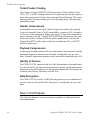
1.
From the Main Menu shown in figure 2-1, select the Administration
command by entering A at the command prompt.
C h ap t e r 2 - Q u i c k S t a r t C o n f i g u r a t i o n
2-3
I n i t i a l C o n f i gu r a t i o n
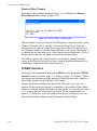
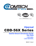
Figure 2-1 Main Menu screen
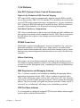
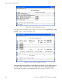
2.
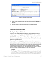
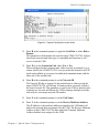
From the Administration screen shown in figure 2-2, select the Features
Configuration command by entering F at the command prompt.
Figure 2-2 Administration screen
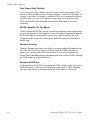
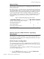
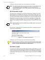
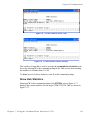
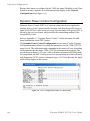
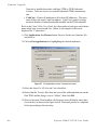
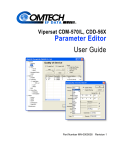
3.
2-4
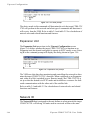
From the Feature Configuration menu shown in figure 2-3, verify
whether or not the Vipersat Feature Codes are Available (appears as
shown in the figure). These codes are entered prior to shipment from the
factory; however, if the codes display as Unavailable, they will have to be
re-entered.
Vipersat CDM-570/570L User Guide
I n i t i a l C o n f i g u r a t io n
Figure 2-3 Feature Configuration screen
To enter the feature codes, enter Y at the command prompt, then enter the 20
digit FAST Feature Code, as shown in figure 2-4.
Figure 2-4 FAST Feature Code dialog
Tip: The network administrator will have the FAST Feature codes. These are
generated and stored by the unit serial number for the target CDM-570/
570L. The target unit’s serial number can be found on the rear of the unit
chassis.
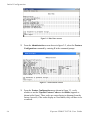
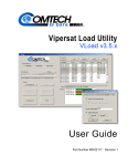
4.
After entering the FAST Feature code, return to the Administration
screen (shown in figure 2-2) by entering X at the command prompt from
the Feature Configuration menu. Ensure that the Working Mode is set to
Router-Vipersat.
If it is not, enter C and change the setting by selecting 4, as shown in
figure 2-5. The unit will automatically reboot in order to implement the
change for this setting.
C h ap t e r 2 - Q u i c k S t a r t C o n f i g u r a t i o n
2-5
I n i t i a l C o n f i gu r a t i o n
Figure 2-5 Working Mode dialog
5.
When the reboot is completed, return to the Feature Configuration screen
and configure the settings for Vipersat STDMA and Auto Switching
according to the table below.
Table 2-2 Vipersat Feature Configuration
Unit Role
Hub
Hub Expansion
Remote
Remote Expansion
6.
Vipersat
Enabled
Enabled
Enabled
Enabled
STDMA
(optional) Enabled
Disabled
(optional) Enabled
Disabled
Auto Switching
(optional) Enabled
Disabled
(optional) Enabled
Disabled
Save the settings to flash by entering S at the command prompt.
Set the IP Address
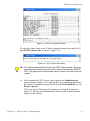
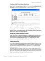
1.
2-6
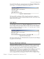
From the Main Menu, enter I to access the Interface Configuration menu
screen, then enter E to access the Ethernet Interface screen, as shown in
figure 2-6.
Vipersat CDM-570/570L User Guide
I n i t i a l C o n f i g u r a t io n
Figure 2-6 Ethernet Interface screen
2.
Enter I at the command prompt, and enter the designated IP address for
this unit.
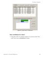
3.
Save the settings to flash by entering S at the command prompt.
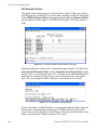
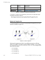
Configure the Route Table
Routing in a Vipersat Network
CDM-570/570L Modem Routers operating in Vipersat mode do not use the
small or large network described in the CDM-570/570L Installation and Operation Manual. There is no HDLC address in a Vipersat network; instead, the
CDM-570/570L role designation — Hub or Remote, Expansion unit or not —
determines routing rules that prevent multicast loops. This simplifies the configuration of a Vipersat network.
Because satellite networks are often used as extensions for access to services
such as the Internet or the PSTN, they lend themselves quite readily to private
addressing. For example, to provide Internet access to the satellite network, only
the Hub requires a public IP address in order for the entire satellite network that
is controlled by the Hub to have access to the Internet backbone. Utilizing
Network Address Translation (NAT), the administrator can effectively address
the network using a minimum number of static route statements.
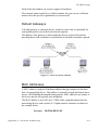
Example:
The IP address 172.16.0.0 is the private address network number for class B
networks. If there is a router at the Hub with a connection to the Internet, the
operator can define the local network as a class B. If the operator splits the
C h ap t e r 2 - Q u i c k S t a r t C o n f i g u r a t i o n
2-7
I n i t i a l C o n f i gu r a t i o n
Class B in half and points the upper half toward the satellite there will be
over 16000 usable addresses at the Hub as well as at the Remotes. For details
on IP addressing, refer to Appendix A, "Network Addressing".
By putting the one route statement “Remotes 172.16.128.0/17 Wan to Sat”
in the TDM Hub modem, and by using the route statement “GW 0.0.0.0/0
Wan to Sat” at each of the remote modems, the network will successfully
route packets. The remotes can then be sub-netted as class C networks or
below. Additional routers at the remotes can be added for unusually large
sites, allowing an additional layer of NAT without requiring any more
explicit routing within the Vipersat Modem/Routers.
Refer to the CDM-570/570L Installation and Operation Manual for additional
information on entering routes.
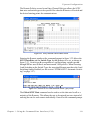
Creating the Routes
The following procedure outlines the basic route structure that the target
CDM-570/570L will require for its role in the network. One of the key routes
that must be created is a gateway address for routing the data traffic that is
received by the unit.
2-8
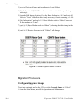
1.
From the Main Menu shown in figure 2-1, select Route Table by entering
R at the command prompt.
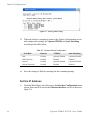
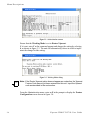
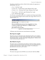
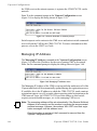
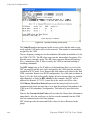
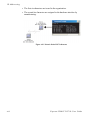
2.
From the Configuring the Route Table screen shown in figure 2-7, enter
1 at the command prompt to set the first route that will define the default
gateway.
Vipersat CDM-570/570L User Guide
I n i t i a l C o n f i g u r a t io n
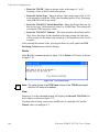
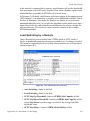
Figure 2-7 Configuring the Route Table screen
In a Hub configuration, the default route will typically point to a router on the
same LAN as the CDM-570/570L Hub unit.
In a Remote configuration, the default route will typically point to the satellite
modem used for communications back to the Hub.
3.
When prompted, enter the Route Name (GW), the IP Address, the
Number of Bits in the subnet mask, the Route Interface (Ethernet or Satellite), and the Next Hop address. The system administrator can supply
this information, if necessary.
In a Hub role, for example, enter the name of the route (e.g., DFG), enter
0.0.0.0 for the destination IP address and 0 for the mask, enter E for
Ethernet interface, then enter the IP address of the appropriate router or
modem for the next hop.
If this Hub unit is providing the TDM outbound, a route statement or statements defining satellite communications with the Remote units must be
entered as well. One recommended option is to enter a single super-route
that will handle satellite communications with all of the remote subnets; an
example of this is shown as Route002 in figure 2-7, above.
4.
Enter S at the command prompt in figure 2-7 to save the settings to flash.
C h ap t e r 2 - Q u i c k S t a r t C o n f i g u r a t i o n
2-9
I n i t i a l C o n f i gu r a t i o n
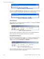
Set the Satellite Modem Configuration
NOTE
1.
Enter M from the Main Menu, then enter C from the Satellite Modem
menu to access the Configuration screen.
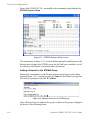
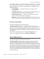
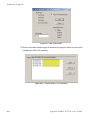
2.
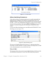
Enter T to access the Tx Configuration screen shown in figure 2-8. Set
the Tx parameters for Frequency, Data Rate, FEC, Code Rate, and
Modulation as specified by the network administrator.
Note: Only Turbo Product Coding is acceptable for FEC when the CDM-570/
570L is running in Vipersat mode.
Figure 2-8 Tx Configuration screen
3.
Enter R to access the Rx Configuration screen, and set the Rx parameters
as specified by the network administrator.
4.
Save the settings to flash by entering S at the command prompt.
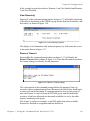
Set the Vipersat Configuration
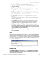
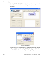
1.
2-10
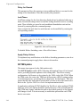
Enter V at the Main Menu command prompt shown in figure 2-1 to select
the Vipersat Configuration menu shown in figure 2-9.
Vipersat CDM-570/570L User Guide
I n i t i a l C o n f i g u r a t io n
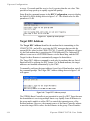
Figure 2-9 Vipersat Configuration screen (Hub)
2.
Enter R at the command prompt to toggle the Unit Role to either Hub or
Remote.
This parameter will determine the role the target CDM-570/570L will perform in the network and what type of commands and functions it will
receive from the VMS.
3.
Enter E to set the Expansion Unit value (Yes or No).
When configured as an expansion unit, either as a hub (switched) or as a
remote (mesh), the CDM-570/570L is set up so that the demod is in SCPC
mode and available as a resource for dedicated communications with the
other end of the satellite link.
4.
Enter B at the command prompt to set the Network ID.
The Network ID that is assigned to the unit defines to what network the
target CDM-570/570L will belong. All units used in a network will have
the same Network ID. This parameter is used by the VMS to identify units
common to a network and allows the VMS to manage multiple networks,
each with its own unique network ID number.
5.
Enter N at the command prompt to set the Unit Name.
6.
Enter V at the command prompt to set the Receive Multicast Address.
This IP address is the multicast address assigned to the VMS and to all
units in the network that are managed by the VMS. The Receive Multicast
Address of this CDM-570/570L must match the Transmit Multicast
Address that has been assigned to the VMS.
C h ap t e r 2 - Q u i c k S t a r t C o n f i g u r a t i o n
2-11
I n i t i a l C o n f i gu r a t i o n
7.
Enter I at the command prompt to set the Managing IP Address.
The Managing IP Address is the IP address of the VMS server.
8.
Enter H to go to the Home State Configuration menu screen, then enter
W to set the current configuration as the Home State.
9.
Save the settings to flash by entering S at the command prompt.
This completes the initial configuration of a CDM-570/570L from the factory
default settings to a functioning, Vipersat-enabled unit. Additional configuration parameters must be set depending on the network requirements for a
specific application.
Refer to Chapter 3, “Using the Command Line Interface,” for additional details
on configuring the target Vipersat CDM-570/570L.
2-12
Vipersat CDM-570/570L User Guide
CHAPTER
USING THE COMMAND LINE INTERFACE
(CLI)
General
This chapter describes the use of the CLI for configuring and monitoring the
CDM-570/570L Modem Router in a Vipersat network. Each CLI screen related
to a CDM-570/570L operating in Vipersat mode is presented, along with a
detailed description of the available commands. For descriptions of all other
screens, refer to the CDM-570/570L Installation and Operation Manual.
Access to the CLI is provided through either the Console port (local, RS-232)
or the 10/100BaseT Ethernet Traffic port (Telnet, IP). Access via Telnet
requires login with password, Console access does not require login. The
screens presented in this document are as they appear when the CDM-570/570L
is accessed using Telnet.
When a Telnet terminal connection is made, the CDM-570/570L responds with
a Login prompt. The factory defaults are:
Login: comtech
Password: comtech
Once the operator has logged in, the Main Menu shown in figure 3-1 is
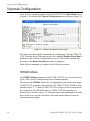
displayed.
C h ap t e r 3 - U s i n g t h e C o m m a n d L in e I n t e r f a c e ( C L I )
3-1
General
Common Screen Commands
The following commands appear on each of the menu screens:
Save Parameters to Permanent Storage
To Save the current parameter settings to permanent storage, enter S at the
command prompt. This command saves all data that has been entered from any
of the CLI screens since the last save was executed. Exiting a screen without
saving after parameters have been changed does not mean that the changes are
not applied. However, if these changes are not saved prior to a system reset or
power cycle, they will be lost.
Exit
To Exit the current menu screen and return to the previous screen in the menu
tree, enter X at the command prompt.
Telnet Logout
Enter L at the command prompt to Logout of the Telnet session. This command
appears only when connected via Telnet.
3-2
Vipersat CDM-570/570L User Guide
Menu Descriptions
Menu Descriptions
This section details the CLI command menus and briefly discusses the function
of each of the commands available on each menu.
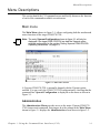
Main menu
The Main Menu, shown in figure 3-1, allows configuring both the modem and
router functions of the target CDM-570/570L.
NOTE
Note: The entry Vipersat Configuration shown in figure 3-1 will only be
displayed if the target CDM-570/570L has had the Vipersat option
enabled as described in the section “Setting Vipersat CDM-570/570L
Operating Parameters” on page 2-3.
Figure 3-1 Main Menu screen
A Vipersat CDM-570/570L is normally shipped with the Vipersat option
enabled. You can verify the CDM-570/570L configuration by checking that the
command line Vipersat Configuration is displayed on the menu as shown in
Figure 3-1.
Administration
The Administration Menu provides access to the major Vipersat CDM-570/
570L features and commands. Entering an A at the prompt in the Main Menu,
shown in figure 3-1 displays the Administration screen shown in figure 3-2.
C h ap t e r 3 - U s i n g t h e C o m m a n d L in e I n t e r f a c e ( C L I )
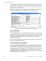
3-3
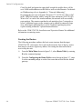
Menu Descriptions
Figure 3-2 Administration screen
Ensure that the Working Mode is set to Router-Vipersat.
If it is not, enter C at the command prompt and change the setting by selecting
4, as shown in figure 3-3. The unit will automatically reboot in order to implement the change for this setting.
Figure 3-3 Working Mode dialog
NOTE
Note: If the Router-Vipersat option does not appear as a selection, the Vipersat
Feature Code has not yet been entered into this unit. Input the Vipersat
code as described in the next section.
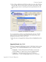
From the Administration menu, enter an F at the prompt to display the Feature
Configuration screen shown in figure 3-4.
3-4
Vipersat CDM-570/570L User Guide
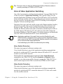
Menu Descriptions
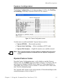
Feature Configuration
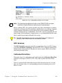
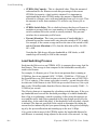
The Feature Configuration screen shown in figure 3-4 allows the Enabling
and Disabling of the major Vipersat CDM-570/570L features.
Figure 3-4 Feature Configuration screen
Use this menu to enable and disable Vipersat features such as:
• Vipersat STDMA — Burst mode operation
• Vipersat Auto Switching — Allows switching to SCPC mode
• Vipersat File Streamer — Rapid file transfers over satellite network
NOTE
Note: These Vipersat features must be enabled or disabled using this menu.
They cannot be enabled or disabled from the Vipersat Configuration
screen.
Vipersat Feature Codes
From the Feature Configuration menu, verify whether or not the Vipersat
Feature Codes are Available (appears as shown in figure 3-4). These codes are
entered prior to shipment from the factory; however, if the codes display as
Unavailable, they will have to be re-entered. To enter the FAST Feature code,
enter Y at the command prompt.
The Vipersat FAST Feature Code can be entered as 20 hexidecimal digits at the
command prompt as shown in figure 3-5.
C h ap t e r 3 - U s i n g t h e C o m m a n d L in e I n t e r f a c e ( C L I )
3-5
Menu Descriptions
Figure 3-5 FAST Feature Code dialog
Tip: Contact either the network administrator or Comtech Vipersat Networks
Customer Support to obtain the FAST Feature code. A convenient option
is to use the Vipersat Vload utility to manage Feature codes.
Vipersat Management
This item is an information only display and indicates whether Vipersat
Management is enabled or disabled in the target Vipersat CDM-570/570L.
Activation of the Vipersat Feature Code automatically enables the Vipersat
Management feature.
Caution: This command must be Enabled in order to utilize any of the Vipersat
capabilities of the CDM-570/570L.
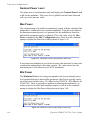
Vipersat STDMA
In order to utilize the Vipersat STDMA feature (burst mode) in the target
Vipersat CDM-570/570L, this feature must be Enabled. Enter A at the
command prompt to toggle On or Off.
Refer to table 2-2 for the relationship between Unit Role and STDMA. For a
Hub STDMA Burst Controller or a Remote STDMA modem, this feature must
be Enabled. For a private point-to-point SCPC modem, Hub or Remote, this
feature must be Disabled.
Vipersat Auto Switching
The Vipersat Auto Switching feature allows the CDM-570/570L to automatically adjust to varying bandwidth demands in the Vipersat network by switching between STDMA and SCPC connections for Load, Application, ToS, and
QoS. Auto switching must be Enabled on a CDM-570/570L if that modem will
be sending any switch requests to the VMS. Refer to table 2-2 for the relationship between Unit Role and Auto Switching.
To activate the Vipersat Auto Switching capabilities of the target CDM-570/
570L, toggle the Auto Switching command to Enabled by entering W at the
command prompt.
3-6
Vipersat CDM-570/570L User Guide
Menu Descriptions
See the section “STDMA/SCPC Automatic Switching” on page 3-27 for more
details on the use of this feature. For additional information, refer to Appendix
B, “Automatic Switching,”.
Vipersat File Streamer
Vipersat File Streamer (VFS) is an optional feature that allows rapid file transfers over the satellite network between host PCs that are running the client VFS
application. To activate the Vipersat File Streaming capabilities of the target
CDM-570/570L, toggle this command to Enabled by entering R at the
command prompt.
Once the parameters on the Feature Configuration screen have been set as
desired, return to the Main Menu and enter the V command to display the
Vipersat Configuration screen shown in figure 3-6.
C h ap t e r 3 - U s i n g t h e C o m m a n d L in e I n t e r f a c e ( C L I )
3-7
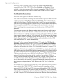
V i p e r s a t C o nf i g u r a t i o n
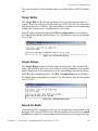
Vipersat Configuration
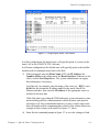
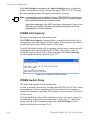
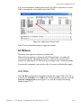
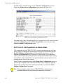
Enter V at the command prompt from the CDM-570/570L Main Menu shown
in figure 3-1 to display the Vipersat Configuration screen shown in figure 3-6.
Figure 3-6 Vipersat Configuration screen (Hub)
This menu lists the available commands for configuring a Vipersat CDM-570/
570L. Note that for the Hub modem only, the command Primary Heart Beat is
displayed in the Vipersat Configuration screen. For the Remote modem only,
the status of the Home State Revert setting is displayed.
Each of these commands is explained in the following sections.
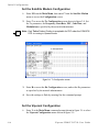
STDMA Mode
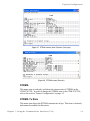
The STDMA Mode parameters for this CDM-570/570L are accessed by entering T at the Vipersat Configuration screen command prompt.
The items in the STDMA menu will vary depending on the function the target
CDM-570/570L performs in the network. The CDM-570/570L STDMA menu
shown in figure 3-7 is from a CDM-570/570L serving as a Hub in the network.
For comparison, the STDMA menu for a CDM-570/570L operating as a
Remote unit is shown in figure 3-8. Note that some of the command items differ
between these two screens, and most of the items on the Remote screen are
information-only display.
3-8
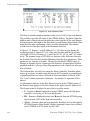
Vipersat CDM-570/570L User Guide
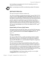
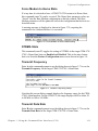
V i p e r s a t C o n f i g u r a t io n
Figure 3-7 STDMA screen (Hub, Dynamic Cycle type)
Figure 3-8 STDMA screen (Remote)
STDMA
This menu item is read-only and shows the current state of STDMA in the
CDM-570/570L. In order to change the STDMA state in the CDM-570/570L,
refer to the section “Feature Configuration” on page 3-5.
STDMA Tx Rate
This menu item shows the STDMA transmit rate in bps. This item is read-only
and cannot be modified in this menu.
C h ap t e r 3 - U s i n g t h e C o m m a n d L in e I n t e r f a c e ( C L I )
3-9
V i p e r s a t C o nf i g u r a t i o n
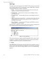
Hub Type
This menu item is only displayed if the CDM-570/570L is being used as a Hub
in the network, and provides the functionality for the STDMA Burst Controller.
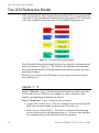
Vipersat STDMA has five modes of operation:
• Fixed — all remotes get the same data slot time (slot size) in the cycle,
regardless of activity. Cycle time is fixed also.
• Dynamic Slot — data slot time of remotes vary according to activity,
cycle time does not.
• Dynamic Cycle — slot time and cycle time vary according to activity of
remotes.
• GIR (Guaranteed Information Rate) — each remote always has at least the
minimum data slot size when needed, and cycle time is variable up to a
maximum of one second.
• Entry Channel — remotes run in SCPC mode, but STDMA is used for
maintenance and control channel.
The Hub can be configured to operate as one of the five types by entering a T at
the command prompt to display the dialog shown in figure 3-9.
Figure 3-9 Hub Type prompt
This selection determines whether available bandwidth will be a static (fixed)
assignment, or whether bandwidth allocation will be dynamic with automatic
switching to dynamically optimize bandwidth utilization.
1 – Fixed
In the Fixed mode, all remotes have the same data slot size regardless of type of
traffic or load. This mode minimizes the amount of jitter between remote transmission times, and is useful for tuning STDMA as well as for troubleshooting
purposes.
3-10
Vipersat CDM-570/570L User Guide
V i p e r s a t C o n f i g u r a t io n
2 – Dynamic Slot
In the Dynamic Slot mode, slot size is adjusted each cycle depending on the
activity during the previous cycle. The slot size for each remote is computed
based on the time (at the current data rate) needed to transmit all the bytes in
queue. If the result is less than the minimum slot size or more than the maximum slot size, the slot is adjusted accordingly. This mode allows the burst
controller to provide additional slot time in the cycle to remotes with higher
traffic demands, increasing throughput and alleviating congestion.
3 – Dynamic Cycle
In the Dynamic Cycle mode, available bandwidth is allocated to remotes
proportionally based on their current bandwidth needs. The bandwidth requirements are determined by the number of bytes in queue for each remote divided
by the total number of bytes in queue for all remotes to determine the percentage of bandwidth to allocate for each remote. This mode provides improved
efficiency of STDMA due to faster cycle times during periods of light traffic
demands, thus providing minimum latency for the current load.
4 – GIR
In the GIR mode, the initial computed slot size value is the same as in the
Dynamic Cycle mode except there is no maximum limit. After all remotes have
been assigned slots, the burst map is checked to see if the total cycle length
exceeds one second. If not, then all requirements are satisfied and the burst map
is complete. However, if the cycle is greater than one second, then the slots are
adjusted proportionally so that all remotes receive at least their guaranteed rate
plus whatever excess is still available.
GIR mode allows guaranteed information rates to be set for each remote in the
group. When the one second restriction is exceeded, remotes without a specified
GIR are reduced to the global minimum slot size and the remaining bandwidth
is distributed to remotes that have been assigned a GIR rate, thus ensuring additional bandwidth to these units when needed.
NOTE
Note: GIR allocations are restricted so that assigned GIR totals cannot exceed
the available bandwidth to insure proper bandwidth allocation when the
network is overloaded.
The GIR setting for each Remote is specified using the STDMA Remote Policies screen (refer to the section “Set Remote Policies” on page 3-20). When
combined with Auto switching, GIR allows trigger points to be set where the
Remote will jump out into SCPC mode. This is done using the Load Switch
setting. Note that, for this function, Auto switching must be Enabled on this
Hub unit, and corresponding Remote modems must be configured with Auto
C h ap t e r 3 - U s i n g t h e C o m m a n d L in e I n t e r f a c e ( C L I )
3-11
V i p e r s a t C o nf i g u r a t i o n
switching and Load switching Enabled. Also, the settings for Step Up and Step
Down Threshold values should be adjusted as necessary for the application.
5 – Entry Channel
The Entry Channel mode provides remotes in the group with a shared channel
in which they can gain initial access to the network. Since very small STDMA
data rates are required in this configuration, a larger number of remotes can
share the cycle. As soon as the Hub receives an STDMA ACK from the
Remote, it initiates an immediate switch to SCPC mode based on the policy set
for that Remote. Note that the switch occurs as soon as the Hub receives an
ACK even though there may not be traffic at that time. The persistence of the
link will be determined by the unit’s flag settings.
When choosing Entry Channel as the Hub type for the STDMA Controller, the
Auto switching feature must be Enabled on this Hub unit, and switching policies
for the remotes must be configured (refer to the section “Set Remote Policies”
on page 3-20). Corresponding Remote modems must be configured with Auto
switching and Load switching Enabled. Note that the settings for Step Up and
Step Down Threshold values should be adjusted as necessary for the application.
This mode is designed to accommodate the needs of a Remote that will not be
continuously connected to the network, but which has the need to be able to
make an on-demand connection when required, such as in a mobile application.
In the event of a power outage, Entry Channel provides a bandwidth-efficient
method for remotes with low latency requirements to re-enter the network once
power is restored.
Refer to Appendix B, “Automatic Switching,” for additional information on
how each of the bandwidth allocation modes functions and the parameters used
to calculate the commands for each mode.
Group ID
The STDMA Group ID number defines a group of equipment (Hub and
Remote units) that will respond to the output of a single STDMA burst controller. This group is addressable within a network which, in turn, is defined by the
Network ID number assigned to the CDM-570/570L.
Allocation of bandwidth is shared among the remotes in an STDMA group.
Depending on the number of remotes in a network, a Hub may have multiple
burst controllers, each with its own set of remotes. This is accomplished by
assigning a unique Group ID number to each controller and its associated
remotes.
NOTE
3-12
Note: The STDMA Group ID number and the Network ID number are independent. There can be multiple STDMA groups within a single network.
Vipersat CDM-570/570L User Guide
V i p e r s a t C o n f i g u r a t io n
The target CDM-570/570L Group ID can be modified by entering an I at the
command prompt to display the dialog shown in figure 3-10.
Figure 3-10 Group ID prompt
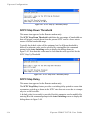
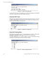
STDMA Power Hunt
This menu item appears for Remote modems only.
Should link reception from a Remote be incorrect or impaired (e.g., poor environmental conditions), the STDMA Power Hunt feature is an option on the
Remote modem that automatically adjusts the Remote transmit power to ensure
that burst map acknowledgements from that unit are received by the Hub burst
controller. When enabled, the burst controller sets a flag in the burst map that
indicates it is not receiving acknowledgements from an enabled Remote. When
the Remote receives the burst map, it will see the flag and automatically
increase power by 3 dB above the default or Home State setting. If this closes
the link, the burst controller will clear the flag. Note that if the 3 dB increase is
more than is necessary, DPC will make a down adjustment to the appropriate
level and this adjustment will be added to the DPC Offset.
This feature option is Enabled/Disabled by entering H at the command prompt.
Low Data Rate Fast Acquisition
This menu item is a toggle used to Enable or Disable the Vipersat Burst Fast
Acquisition Timing (BFAT) feature that functions at low data rates (64 kbps to
256 kbps). This feature allows for significantly faster acquisition times at these
data rates, even with higher noise, resulting in improved efficiency of the shared
STDMA channel. Since signal lock is faster at higher data rates, BFAT is not
active above 256 kbps.
Entering A at the command prompt will toggle this feature On or Off.
This feature requires Base Modem firmware version 1.5.2 or later, together with
Router firmware version 1.5.3 or later. Modems must be operating at either 3/4
QPSK or .95 QPSK in order to utilize BFAT.
C h ap t e r 3 - U s i n g t h e C o m m a n d L in e I n t e r f a c e ( C L I )
3-13
V i p e r s a t C o nf i g u r a t i o n
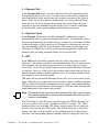
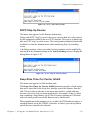
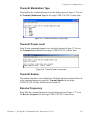
Burstmap Multicast IP
This menu item is used to define the IP address for the Burstmap Multicast that
is sent out by the STDMA burst controller at the Hub to all of the associated
remotes in that group. This address must be the same for all members of the
group. The burstmap is a proprietary message sent from the Hub to all remotes,
at regular intervals, specifying the relative start time and duration for each
terminal to transmit.
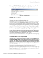
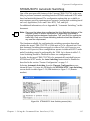
To change the current address, enter N at the command prompt to display the
dialog shown in figure 3-11.
Figure 3-11 Burstmap Multicast IP prompt
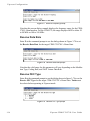
Outbound IP
This menu item, which appears for all Hub configurations, displays the current
Outbound IP address. This specifies the Hub device that is supplying the TDM
outbound to the satellite (typically a CDM-570/570L). Specifying this address is
necessary when configuring a Hub that utilizes a burst controller that is a separate device from the TDM modem.
This address must also be defined when the DPC feature is to be used. The
Outbound IP address will be the same as the burst controller IP address when
the burst controller and the TDM modem are the same device.
To define the TDM outbound address, enter O at the command prompt. The
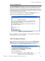
dialog shown in figure 3-12 will be displayed.
Figure 3-12 Outbound IP prompt
3-14
Vipersat CDM-570/570L User Guide
V i p e r s a t C o n f i g u r a t io n
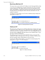
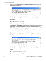
Cycles Per Burst Map
This menu item, which appears for all Hub types except Dynamic Cycle and
GIR, displays the number of spin cycles that will occur prior to each broadcast
of the Burst Map by the burst controller to the remotes. One cycle is the amount
of time it takes for all remotes in a group to burst on the common channel. The
burst map provides each remote with its allocated bandwidth and position in the
cycle.
For Dynamic Cycle and GIR configurations, the number of cycles is automatically set to one in order to ensure optimum performance for these Hub types.
This parameter can be modified from the Hub CDM-570/570L by entering a C
at the command prompt as shown in figure 3-13.
Figure 3-13 Cycles per Burst Map prompt
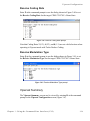
On Remote units, this menu item is an information-only display.
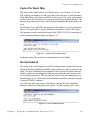
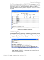
Slot Guardband
This menu item, which appears for all Hub configurations, displays the current
length of the Slot Guardband in milliseconds and in bytes for the remotes in the
group. The Slot Guardband is the amount of time between the point when one
remote completes transmitting data and the point when the next remote in the
cycle begins transmitting. This prevents the remote from overrunning the next
terminal in the cycle. The setting for this parameter should be obtained using the
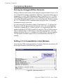
Vipersat STDMA Calculator.
On a Hub unit, this value can be modified by entering G at the command
prompt to display the dialog shown in figure 3-14 and entering a new value.
Figure 3-14 Slot Guardband prompt
C h ap t e r 3 - U s i n g t h e C o m m a n d L in e I n t e r f a c e ( C L I )
3-15
V i p e r s a t C o nf i g u r a t i o n
On Remote units, this menu item is an information-only display.
NOTE
Note: The value entered at the command line in figure 3-14 is in milliseconds.
The corresponding value expressed in bytes is calculated by the
CDM-570/570L based on the STDMA transmit bit rate as shown in the
menu in figure 3-7.
Slot Preamble Length
This menu item, which appears in all Hub configurations, displays the current
Slot Preamble size in milliseconds and bytes for the remotes in the group. The
Slot Preamble is the period between when the remote begins to transmit (sends
an ACK) to the Hub and when the first data packet is sent. This allows time for
signal lock to occur before data is sent, thus preventing data loss. Higher data
rates allow for a shorter preamble, since it is easier to achieve signal lock. The
setting for this parameter should be obtained using the Vipersat STDMA Calculator.
NOTE
Note: When the BFAT feature is enabled, the preamble length is set automatically for the unit.
On a Hub unit, entering P at the command prompt allows changing the preamble duration in milliseconds.
Figure 3-15 Slot Preamble Length prompt
On Remote units, this menu item is an information-only display.
Tip: Refer to the Viper Calculator for determining Slot Preamble Length values
to enter at the command prompt. For a copy of the latest Viper Calculator,
contact a Comtech Vipersat Networks representative.
Slot Data Length
This menu item displays the Slot Data Length in milli-seconds and bytes for the
remotes in the group, and represents the amount of data that can be transmitted
or received in one spin of the STDMA cycle by each of the Remotes belonging
to that group. This is the amount of time that the remote is provided to send data
in the cycle.
3-16
Vipersat CDM-570/570L User Guide
V i p e r s a t C o n f i g u r a t io n
Depending on the Hub type that is defined for the modem, the appearance of
this parameter will vary:
• Fixed – Slot Data Length
• Dynamic Slot – Nominal Data Length, Minimum Data Length
• Dynamic Cycle – Maximum Data Length, Minimum Data Length
• Entry Channel – Slot Data Length, Minimum Data Length
• GIR – Minimum Data Length
On a Hub unit, entering B and M at the command prompt brings up the dialogs
for specifying the data length in milli-seconds for the target CDM-570/570L, as
shown in figure 3-16.
Figure 3-16 Slot Data Length (Nominal)
On Remote units, this menu item is an information-only display.
Slot Cycle Length
This menu item is for information only and displays the Slot Cycle Length in
milli-seconds and bytes for the remotes in the group. This value represents the
total amount of time—preamble, data length, and guardband—allocated to the
remote modem during one spin cycle.
Slot Start in Cycle
This menu item is an information-only display for Remote modems, and indicates how much time passes from the start of the spin cycle until this Remote is
provided a time slot. In the example shown in figure 3-8, the Remote is
provided the first slot in the cycle (0 mSec).
Set Remotes
This menu item appears in the STDMA screen when the Unit Role is Hub.
C h ap t e r 3 - U s i n g t h e C o m m a n d L in e I n t e r f a c e ( C L I )
3-17
V i p e r s a t C o nf i g u r a t i o n
From a Hub CDM-570/570L, entering R at the command prompt displays the
STDMA Remotes Menu.
Figure 3-17 STDMA Remotes Menu screen
The menu shown in figure 3-17 is used to define and make modifications to the
Remotes that belong to the STDMA group for the Hub burst controller, as well
as to display each Remote’s burstmap status information.
Adding a Remote to the STDMA Group
Entering the item number for the Remote modem/router brings up the dialog
shown in figure 3-18. A prompt to enter the Name for the Remote unit appears,
followed by a prompt to enter the IP Address.
Figure 3-18 Adding a Remote to the STDMA group
Once a Remote has been added to the group, its Status in the group is displayed
by the use of the following letters:
3-18
Vipersat CDM-570/570L User Guide
V i p e r s a t C o n f i g u r a t io n
• U = Used – This Remote is being used in the burstmap.
Once a remote has been added to the STDMA group, this status will
always be displayed.
• B = Burstmap – This Remote is currently in the burstmap.
This status will be displayed unless the remote has been removed (R),
disabled (D), or switched (S) out of the STDMA burstmap.
• R = Removed – This Remote is currently removed from the burstmap.
When displayed, this status indicates that the Hub has removed this remote
from the burstmap due to a communications fault.
• D = Disabled – This Remote is currently disabled and is not in the
burstmap.
This status will be displayed when a remote is manually disabled by the
operator or administrator.
• S = Switched – This Remote is currently switched into SCPC mode.
When displayed, this status indicates that the VMS has automatically
switched the remote out of the burstmap and into SCPC operation.
• H = Home State Revert – This Remote is not currently receiving burst
maps. When a remote, stuck in SCPC mode by failure to receive a VMS
revert command, sees the burst map with this flag set, it will automatically
revert to its home state and STDMA mode.
• CF – This Remote has not sent an acknowledgement to the burst controller
since it was enabled.
Base
Entering a B at the command prompt in figure 3-17 allows entering the Remote
number to start displaying remotes in this menu screen. Entering the number 1,
as shown in figure 3-17, displays nine remotes, 1 through 9. If the number 4 had
been entered, the display would show the nine remotes starting with remote 4
(i.e., remotes 4 through 12).
Figure 3-19 Modifying Remote Display Base
Remote Count
The Remote Count menu item in figure 3-17 is an information only display
showing the total number of Remotes that currently belong to the STDMA
group for this Hub burst controller.
C h ap t e r 3 - U s i n g t h e C o m m a n d L in e I n t e r f a c e ( C L I )
3-19
V i p e r s a t C o nf i g u r a t i o n
Set Remote Policies
This menu item, which appears for GIR and Entry Channel Hub types, allows
each Remote to be configured for specific data switching conditions. Entering P
at the STDMA Remotes Menu command prompt displays the Remote Policies
screens shown in either figure 3-20 (GIR Hub) or figure 3-22 (Entry Channel
Hub).
Figure 3-20 STDMA Remote Policies screen (GIR Hub)
Entering the Remote number at the command prompt in figure 3-20 allows the
Guaranteed Information Rate and the Automatic Load Switch Rate for that
Remote to be set, as shown in figure 3-21. Note that the Available Bandwidth is
displayed for reference in this screen to assist with entering the appropriate
rates. The cycle length for GIR is limited to a maximum of one second.
Figure 3-21 GIR Remote Policies prompt
Set the Automatic Load Switch Rate to a value greater than the GIR to allow the
Remote to be automatically switched out of STDMA and into SCPC mode
when traffic exceeds the GIR. A Switch Rate of 0 will prevent the Remote from
being switched out of STDMA and into SCPC mode.
3-20
Vipersat CDM-570/570L User Guide
V i p e r s a t C o n f i g u r a t io n
The Remote Policies screen for an Entry Channel Hub type allows the SCPC
data rates and switch types to be specified for when the Remotes will switch and
the desired starting points for communications.
Figure 3-22 Entry Channel Switch Rates screen
Entering the Remote number at the command prompt in figure 3-22 allows the
SCPC Data Rate and the Switch Type for that Remote to be set, as shown in
figure 3-23. Switch type 0 corresponds to Load Switching; switch types 64
through 255 are user-defined, and must match VMS policies. When choosing
Load Switching as the Switch Type, the associated Remote must have the Load
Switching feature Enabled (see the section “STDMA/SCPC Automatic Switching” on page 3-27).
Figure 3-23 Remote SCPC Data Rate and Switch Type prompt
The Global SCPC Rate command can be used to set the data rate for all or a
majority of the Remotes. This allows the rate to be entered just once instead of
entering the rate for each remote individually. Enter G at the command prompt.
C h ap t e r 3 - U s i n g t h e C o m m a n d L in e I n t e r f a c e ( C L I )
3-21
V i p e r s a t C o nf i g u r a t i o n
Figure 3-24 Global SCPC Data Rate prompt
Similarly, the Global Switch Type command can be used to set the switch type
for all or a majority of the Remotes. Enter H at the command prompt.
Figure 3-25 Global Switch Type prompt
Delete Remote
Entering D at the command prompt shown in figure 3-17 brings up the Delete
Remote dialog shown in figure 3-26.
Figure 3-26 Delete Remote prompt
Enter the number of the Remote CDM-570/570L at the command prompt to
delete it from the STDMA group for this Hub burst controller.
Enable/Disable Remote
Enter E at the command prompt in figure 3-17 to display the dialog shown in
figure 3-27. The Remotes in the STDMA group are displayed, indicating
whether each is currently Enabled (E) or Disabled.
Figure 3-27 Enable/Disable Remote prompt
Enter the number of the Remote at the command prompt to toggle the Remote
from its current Enable/Disable configuration.
3-22
Vipersat CDM-570/570L User Guide
V i p e r s a t C o n f i g u r a t io n
In the example screen shown above, Remotes 1 and 2 are Enabled and Remotes
3 and 4 are Disabled.
View Remote(s)
Entering V at the command prompt shown in figure 3-17 will display the listing
of Remote(s) that belong to the STDMA group for this Hub burst controller, and
their status, as shown in figure 3-28.
Figure 3-28 View Remote(s) screen
The display is for information only and pressing any key will return the screen
to the menu shown in figure 3-17.
Remove Timeout
Entering R at the command prompt shown in figure 3-17 will display the
Remove Timeout dialog shown in figure 3-29. Note that this menu item shows
the current setting (in seconds) for this parameter.
Figure 3-29 Remove Timeout prompt
The value entered at the command prompt defines the amount of time (in
seconds) with no communication from a Remote to the Hub before that Remote
is removed from the Burstmap. If communications are lost for this period of
time, the Remote is removed from the STDMA group, and the bandwidth
resources it had been allocated are then made available for use by the other
remotes remaining in the group.
This feature is useful, for example, in an SNG application where a mobile
Remote has finished its assignment and has shut down.
C h ap t e r 3 - U s i n g t h e C o m m a n d L in e I n t e r f a c e ( C L I )
3-23
V i p e r s a t C o nf i g u r a t i o n
Remove Retry Timeout
Entering T at the command prompt in figure 3-17 will display the Remove
Retry Timeout dialog shown in figure 3-30.
Figure 3-30 Remove Retry Timeout prompt
When a Remote is removed from the STDMA group, as described in the section
“Remove Timeout” above, entering a value in the Remove Retry Timeout
dialog defines the amount of time (in seconds) that is allowed to pass before a
retry attempt is made to return the removed Remote to the group. The Remote is
re-entered into the burst map cycle; if the Remote does not burst back (ACK) to
the Hub burst controller, it is again removed from the Burst Map.
This allows, again using a mobile remote as an example, shutting down the
remote at one location, moving it to a new location, and then automatically reestablishing a connection to the satellite network.
STDMA Statistics
Entering V at the command prompt in the STDMA screen displays the STDMA
Statistics as shown in either figure 3-31 (Hub) or figure 3-32 (Remote). These
screens provide information for the number of Bursts (Remote only), number of
Burst Maps, and the current STDMA Cycle Length.
Because the Remote modem bursts back to the Hub once every cycle, the
number of Bursts displayed should be a multiple of the number of Burst Maps
displayed, with this multiple determined by the number of cycles per burst map
(1, 2, or more) that has been defined at the Hub. For the example shown in
figure 3-32 (Dynamic Cycle), the number of cycles per burst map is one, and
therefore the number of Bursts equals the number of Burst Maps.
3-24
Vipersat CDM-570/570L User Guide
V i p e r s a t C o n f i g u r a t io n
Figure 3-31 STDMA Statistics screen (Hub)
Figure 3-32 STDMA Statistics screen (Remote)
The window of time that is used to average the accumulation of statistics can
be set by entering W at the command prompt in the Hub screen, then entering
the number of seconds (from 1 to 20).
To clear (reset to 0) these statistics, enter C at the command prompt.
Show Hub Statistics
Entering a W at the command prompt in the STDMA screen (figure 3-7)
displays the current statistics for the target CDM-570/570L Hub, as shown in
figure 3-33.
C h ap t e r 3 - U s i n g t h e C o m m a n d L in e I n t e r f a c e ( C L I )
3-25
V i p e r s a t C o nf i g u r a t i o n
Figure 3-33 Hub Statistics screen
The Burst Controller monitors statistics in the received ACK from each Remote.
The statistics report the fill status of the STDMA buffers. The Burst Controller
builds a table of the group and calculates the relative buffer fill for each Remote.
It then calculates the length of the Data Slot for each Remote based on the Minimum Slot Size plus a percentage of the Available Bandwidth. Idle remotes
would receive a Data Slot equal to the Minimum Slot Size.
In figure 3-33, Remote 1 with IP address 10.1.128.1 had activity during the
averaging period. It captured 37.8% of the total slot time and had an average
slot length of 283 ms. Remotes 2, 3, and 4 had 41.5%, 18.1%, and 7.6% respectively. The dynamic range of STDMA is a function of the difference between
the Nominal Data Slot Size and the Minimum Data Slot Size parameters. These
parameters are operator selectable. The speed with which STDMA reacts to
changes in dynamic load is a function of the Statistics Accumulation Window
parameter and the Cycles per Burst Map parameter, both of which are also operator selectable.
The Hub statistics are useful for tuning the Burst Controller. Preamble adjustments, up or down, are made using the missed ACKs statistic; a preamble and/
or guardband that is too short will result in an accumulation of missed ACKs.
The “Cont” column represents continuous—the number of sequential ACKs
missed.
An informative indicator in the Hub Statistics screen is the STDMA status of
the Remotes that appears in the first column to the right of the IP Address list.
The Remote status is displayed in one of three possible modes:
• E – Remote is Enabled and active in the STDMA group; the Hub burst
controller is receiving ACKs from this Remote.
• ER – Remote is Enabled but has been Removed from the STDMA group
due to missed ACKs at the Hub burst controller.
• (Blank) – Remote either has been manually Disabled, such as through the
STDMA Remotes Menu Enable/Disable command, or has been switched
out of STDMA to SCPC mode by the VMS.
3-26
Vipersat CDM-570/570L User Guide
V i p e r s a t C o n f i g u r a t io n
STDMA/SCPC Automatic Switching
One of the most powerful features of the Vipersat CDM-570/570L is the capability to perform Automatic switching between STDMA mode and SCPC mode
based on bandwidth demand. The configuration options that are available to
meet customer-specific requirements are extensive, and include switching based
on Load, Application (Voice and Video RTP), ToS, and QoS.
For additional information, refer to Appendix B, “Automatic Switching,” in this
document.
NOTE
Note: Care must be taken when configuring the Auto Switching features of the
Vipersat system to ensure that there is no duplication or overlap of
switching functions between Application, ToS, and QoS for a particular
traffic flow. Only one of these switching methods should be utilized for
any one flow requirement.
The functions available for configuring the switching operations depend on
whether the target CDM-570/570L is a Hub unit or if it is a Remote unit. Note
that Automatic switching does not apply to either a Hub with Expansion or a
Remote with Expansion; these configurations operate in dedicated SCPC mode
and all switching control is performed by the VMS. As is shown in table 2-2,
Auto Switching should be Disabled for these two configurations.
In order for the target CDM-570/570L to be automatically switched between
STDMA and SCPC modes, the Auto Switching feature must be Enabled as
described in the section “Feature Configuration” on page 3-5.
Selecting Automatic Switching from the Vipersat Configuration screen
shown in figure 3-6 (enter A) will display the STDMA/SCPC Auto Switching
screen shown in either figure 3-34 (Hub modem) or figure 3-35 (Remote
modem).
Figure 3-34 STDMA/SCPC Auto Switching screen (Hub)
C h ap t e r 3 - U s i n g t h e C o m m a n d L in e I n t e r f a c e ( C L I )
3-27
V i p e r s a t C o nf i g u r a t i o n
Load switching is controlled by both the Hub and the Remote, and thus related
commands appear in both screens. The initial Load switch request is made by
the Hub. Once in SCPC mode, subsequent Load switch requests (Step Up, Step
Down) are made by the Remote.
Application switching, ToS switching, and QoS switching are controlled by the
Remote, and thus appear only in the Remote Auto Switching screen.
Figure 3-35 STDMA/SCPC Auto Switching screen (Remote)
Auto Switching
The Auto Switching item is for information only and shows the current configuration of this feature for the target CDM-570/570L. This feature is Enabled and
Disabled as described in the section “Feature Configuration” on page 3-5. Auto
Switching must be Enabled in order to utilize any of the related features/
commands in this menu.
Note that Auto Switching must be Enabled on a Hub STDMA Controller that is
configured for Entry Channel mode.
Current WAN Transmit Mode
The Current WAN Transmit Mode item is for information only and reflects
the current status (STDMA mode or SCPC mode) of the CDM-570/570L. If the
CDM-570/570L is functioning as a Hub in the network, this item will always
read Continuous as shown in figure 3-34. If the CDM-570/570L is functioning
as a Remote in the network and STDMA is enabled, this item will show
STDMA (Burst) when in STDMA mode, as shown in figure 3-35, or Continuous when switched out into SCPC mode.
3-28
Vipersat CDM-570/570L User Guide
V i p e r s a t C o n f i g u r a t io n
Tip: This menu item is useful for determining whether a Remote modem is
currently operating in STDMA or SCPC mode.
Voice & Video Application Switching
One of the four automatic switching functions that the Vipersat CDM-570/570L
is able to perform is Application Switching. The Vipersat CDM-570/570L
provides application switching for non-encrypted SIP and/or H.323 traffic that
is detected on the satellite network. When encryption prevents the detection of
this type of traffic, an alternate means of SCPC switching can be configured
using the ToS auto switching feature.
Detection of the voice and video traffic occurs in the Remote modem classifier,
which looks at traffic that is passed in both directions (Hub-to-Remote and
Remote-to-Hub). Once the Voice and Video Switch Detection features are
enabled, the Remote modem will send an Automatic Switch Request (ASR) to
the VMS when an SIP and/or H.323 call is detected. The ASR contains the
destination IP address of the RTP packets. If available hardware and bandwidth
exist, the VMS will establish the SCPC carrier automatically.
NOTE
Note: Application switching (Voice and Video) must be Enabled for each
CDM-570/570L in a network that is going to perform Application switching in order for the VMS to dynamically optimize network circuit parameters to accommodate these applications.
Load switching by the VMS is not affected by this setting.
Voice Switch Detection
This menu item appears for Remote modems only.
Voice Switch Detection is one of the Application switching commands that
provides for a dedicated SCPC connection when an SIP and/or H.323 voice call
is made over the satellite network.
Entering O at the command prompt toggles the Voice Switch Detection
command for the CDM-570/570L between Enabled and Disabled. When
enabled, a voice data-stream will be detected, causing the CDM-570/570L to
send a switch request to the VMS to switch from STDMA to SCPC mode.
Video Switch Detection
This menu item appears for Remote modems only.
Video Switch Detection is one of the Application switching commands that
provides for a dedicated SCPC connection when an H.323 video call is made
over the satellite network.
C h ap t e r 3 - U s i n g t h e C o m m a n d L in e I n t e r f a c e ( C L I )
3-29
V i p e r s a t C o nf i g u r a t i o n
Entering I at the command prompt toggles the Video Switch Detection
command for the CDM-570/570L between Enabled and Disabled. When
enabled, a video data-stream will be detected, causing the CDM-570/570L to
send a switch request to the VMS to switch from STDMA to SCPC mode.
ToS Switch Detection
This menu item appears for Remote modems only.
One of the four automatic switching functions that the Vipersat CDM-570/570L
is able to perform is ToS (Type of Service) Switching. ToS is defined by an
eight bit field within an IP packet header that is used to set up per-hop-based
QoS rules for prioritizing packets. Because the ToS field remains untouched by
most encryption methods, ToS switching provides an alternative means of
SCPC switching when encryption prevents the detection of SIP and H.323
protocols.
ToS detection occurs in the Remote modem which only looks at traffic that is
passed in the LAN-to-SAT (Remote to Hub) direction. Once the ToS Switch
Detection feature is enabled, the Remote modem will send an ASR to the VMS
when a packet stamped with the ToS is detected. The ASR contains the destination IP address of the ToS stamped packet, the desired SCPC rate, and the VMS
Switch Type (policy #). If available hardware and bandwidth exist, the VMS
will establish the SCPC carrier automatically.
Entering T at the command prompt in figure 3-35 toggles the TOS Switch
Detection command for the CDM-570/570L between Enabled and Disabled.
When enabling ToS switching, the ToS switching control parameters must be
defined as described in the section “ToS Switching Parameters” on page 3-38.
Applying a ToS value to an application (VoIP, IPVC, or priority data) through
either preservation or classification packet stamping allows the Vipersat switching system to function in an encrypted network. Normally in a non-encrypted
Vipersat network, packets are classified by the Remote CDM-570/570L using
protocol classification detection and the results are forwarded to VMS via
VESP (Vipersat External Switching Protocol) or, in legacy VMS systems, via
an ASR (Automatic Switch Request) message. The VMS switch detector
service then applies the required or requested bandwidth using policies which
have been pre-configured in the VMS. Refer to the VMS User’s Guide for
details.
For example, if in a non-encrypted network a voice application service connection is started, the CDM-570/570L’s classifier analyzes signaling and data
protocols (H.323, SIP, & Data RTP) being routed through the CDM-570/570L.
After connection detection, the process waits for data (RTP). Data is normally
sent after the receiving party answers, which then triggers the system to process
an ASR. Using the ToS classification, the detection function allows application3-30
Vipersat CDM-570/570L User Guide
V i p e r s a t C o n f i g u r a t io n
based switching in encrypted networks where the signaling protocols are
encrypted or effectively hidden.
NOTE
Note: Load switching by the VMS is not affected by enabling ToS detection.
QoS Switch Detection
This menu item appears for Remote modems only.
One of the four automatic switching functions that the Vipersat CDM-570/570L
is able to perform is QoS (Quality of Service) Switching. With this feature, an
STDMA to SCPC switch can be initiated based upon any type of IP traffic flow
that matches a defined QoS queue. QoS detection occurs in the Remote modem
classifier, which looks at traffic that is passed in both directions (Hub-toRemote and Remote-to-Hub). When an IP packet matches a defined QoS rule,
the Remote modem sends an ASR to the VMS that contains the destination
address of the detected packet, the defined bit rate, and the policy type. If available hardware and bandwidth exist, the VMS will establish the SCPC carrier
automatically.
Enable Quality of Service (QoS) Feature
The Remote must have the QoS FAST feature code, and the QoS feature must
be enabled in order for the QoS Switch Detection feature to function. The QoS
feature is Enabled/Disabled from the Feature Configuration screen (see
figure 2-3).
Configure QoS Rules
The Vipersat CDM-570/570L is capable of performing automatic switching
based on the QoS rules for a Remote modem. QoS rules can be assigned to
different flow types that are user-defined by any combination of traffic type
protocol (FTP, UDP, RTP, etc.), source/destination IP (specific or range), and/
or Layer 3 source/destination port.
The Vipersat QoS Switching feature is designed to manage single, specific
sessions or flow types, such as a UDP video stream targeted to a specific port.
When defining QoS rules for QoS based switching, it is best to make them as
specific as possible so as to avoid unintended or multiple sessions/flows being
generated with that rule. A QoS rule that creates multiple flows will result in
poor switching performance. With voice traffic, for example, prioritize by using
the VOCE protocol rather than prioritizing with RTP or UDP.
From the Main Menu for the Remote modem, enter Q to access the QoS
Configuration screen, as shown in figure 3-36.
C h ap t e r 3 - U s i n g t h e C o m m a n d L in e I n t e r f a c e ( C L I )
3-31
V i p e r s a t C o nf i g u r a t i o n
Figure 3-36 QoS Configuration screen
Enter Q at the command prompt in figure 3-36 to access the QoS Rules Configuration screen, as shown in figure 3-37.
Figure 3-37 QoS Rules Configuration screen
Configure the desired number of rules that are necessary for the applications to
be used for this network. Refer to the CDM-570/570L Installation and Operation Manual for details on configuring QoS Rules for the CDM-570/570L.
3-32
Vipersat CDM-570/570L User Guide
V i p e r s a t C o n f i g u r a t io n
Configure QoS Rules Based Switching
Enter V at the command prompt in figure 3-36 to access the QoS Rules Based
Switching screen for the Remote modem, as shown in figure 3-38.
Figure 3-38 QoS Rules Based Switching screen
Determine which QoS rules will be used as a basis for performing SCPC
switching, then configure the VMS policy type, the SCPC switch rate, and the
timeout value to be associated with each rule. Assigning a 0 (zero) value means
that no SCPC switch will occur for that rule.
Enable QoS Switch Detection Feature
Once QoS has been enabled and configured as described above, the last step in
implementing QoS switching is to Enable the QoS Switch Detection feature.
Entering Q at the command prompt in figure 3-35 toggles the QoS Switch
Detection feature between Enabled and Disabled.
Load Switching
One of the four automatic switching functions that the Vipersat CDM-570/570L
is able to perform is Load Switching. The system will detect variations in data
rate and can be configured to switch from STDMA to SCPC based on bandwidth requirements.
The initial switch for a Remote CDM-570/570L from STDMA mode to SCPC
mode is determined by the Hub Burst Controller. Once the Remote is switched
into SCPC, any requests to meet additional switching requirments within SCPC
(Step Up or Step Down) are made by the Remote modem.
C h ap t e r 3 - U s i n g t h e C o m m a n d L in e I n t e r f a c e ( C L I )
3-33
V i p e r s a t C o nf i g u r a t i o n
The Load Switching command on the Auto Switching menu is a toggle that
Enables and Disables Load Switching on the target CDM-570/570L. Entering
B at the command prompt will toggle between these two states.
NOTE
Note: Load switching must be Enabled for any CDM-570/570L that will experience changing load conditions in order for the VMS to dynamically optimize network performance on these circuits.
Application switching by the VMS, such as for Voice and/or Video, is not
affected by this setting. However, using Load switching for real-time
applications is not recommended.
STDMA Slot Capacity
This menu item appears for Hub modems only.
The STDMA Slot Capacity command allows setting the threshold or level of
slot capacity at which the Burst Controller sends a switch request to the VMS to
switch the Remote from STDMA mode to SCPC mode.
Typically the default settings will be optimum, but there may be unique network
configurations that require modifying the STDMA slot capacity value. To
change this setting, enter U at the command prompt in the Auto Switching
screen to display the dialog shown in figure 3-39.
Figure 3-39 STDMA Slot Capacity prompt
STDMA Switch Delay
This menu item appears for Hub modems only.
In order to minimize unnecessary switching from STDMA to SCPC due to transient conditions, such as a temporary spike in network traffic for example, a
switch delay parameter is provided. This setting is used to specify a delay before
a switch occurs.
Typically the default values will be optimum, but this value can be changed to
accommodate a unique network configuration or application. To change this
setting, enter W at the command prompt in the Auto Switching screen to
display the dialog shown in figure 3-40.
3-34
Vipersat CDM-570/570L User Guide
V i p e r s a t C o n f i g u r a t io n
Figure 3-40 STDMA Switch Delay prompt
Percent Allocation
This menu item appears for Hub modems only.
The Percent Allocation menu item allows adding a fixed percentage to the
channel bandwidth request to accommodate additional bandwidth requirements
which may occur after the switch is made from STDMA to SCPC mode.
Typically the default value (10%) will be sufficient, but if there may be a larger
bandwidth requirement after the switch, the percent allocation value can be
increased. In choosing a value for this allocation, future bandwidth requirements for the channel must be balanced against efficient bandwidth utilization.
To change this setting, enter E at the command prompt in the Auto Switching
screen to display the dialog shown in figure 3-41.
Figure 3-41 Percent Allocation prompt
SCPC Step Up Threshold
This menu item appears for the Remote modem only.
The SCPC Step Up Threshold establishes the percentage of bandwidth use
that will trigger a switch up from the present SCPC rate to a higher rate to
ensure that there is sufficient bandwidth available for current conditions.
Typically the default value will be optimum, but if a different threshold is
desired, an alternate value can be specified by entering U at the command
prompt in the Auto Switching screen to display the dialog shown in
figure 3-42. Note that this value must be greater than the value specified for the
SCPC Step Down Threshold.
C h ap t e r 3 - U s i n g t h e C o m m a n d L in e I n t e r f a c e ( C L I )
3-35
V i p e r s a t C o nf i g u r a t i o n
Figure 3-42 SCPC Step Up Threshold prompt
SCPC Step Down Threshold
This menu item appears for the Remote modem only.
The SCPC Step Down Threshold establishes the percentage of bandwidth use
that will trigger a switch down from the present SCPC rate to a lower rate to
ensure efficient bandwidth usage.
Typically the default value will be optimum, but if a different threshold is
desired, an alternate value can be specified by entering D at the command
prompt in the Auto Switching screen to display the dialog shown in
figure 3-43. Note that this value must be less than the value specified for the
SCPC Step Up Threshold.
Figure 3-43 SCPC Step Down Threshold prompt
SCPC Step Delay
This menu item appears for the Remote modem only.
The SCPC Step Delay feature provides a switching delay period to ensure that
a premature switch up or down in the SCPC rate does not occur due to a temporary rise or fall in traffic.
A default value (in seconds) is provided, but this parameter can be modified by
entering W at the command prompt in the Auto Switching screen to display the
dialog shown in figure 3-44.
3-36
Vipersat CDM-570/570L User Guide
V i p e r s a t C o n f i g u r a t io n
Figure 3-44 SCPC Step Delay prompt
SCPC Step Up Excess
This menu item appears for the Remote modem only.
During each SCPC Step Up switch, the excess capacity data rate value entered
by this command is added to the new SCPC data rate. This excess is added each
time an SCPC Step Up switch occurs. This setting makes additional bandwidth
available for when the demand arises while minimizing Step Up switching
events.
A default percentage value is provided, but this parameter can be modified by
entering E at the command prompt in the Auto Switching screen to display the
dialog shown in figure 3-45.
Figure 3-45 SCPC Step Up Excess prompt
Keep Alive Timer for Carrier Inhibit
This menu item appears for Hub modems only.
The Keep Alive Timer for Carrier Inhibit parameter provides a fixed setting
that can be specified for the keep alive message sent to the Remotes from the
Hub. This provides an alternate to the burst map which is variable and may
become excessively long in certain applications. An example of this is a burst
map containing a large number (up to 100) of remotes running in ECM mode
where the burst period exceeds the Remote carrier inhibit timer.
When implemented, this parameter is set at either the TDM outbound unit or a
switched demod, not at the STDMA Controller, in order to prevent a problem
should the burst controller be rebooted.
C h ap t e r 3 - U s i n g t h e C o m m a n d L in e I n t e r f a c e ( C L I )
3-37
V i p e r s a t C o nf i g u r a t i o n
Enter C at the command prompt in the Auto Switching screen to display the
dialog shown in figure 3-46.
Figure 3-46 Keep Alive Timer for Carrier Inhibit prompt
Note that this timer setting should be at least three times faster (shorter in duration) than the timer setting at the Remote(s) to ensure that network links are
maintained.
Time for Carrier Inhibit
This menu item appears for the Remote modem only.
The Time for Carrier Inhibit feature provides a time period to be specified for
how long the Remote modem has not received the Burst Map from the Hub
STDMA Controller (loss of link) before that Remote mutes its transmitter. This
feature is useful, for example, in an SNG application for a mobile Remote
whose antenna is no longer aligned with the satellite and should not continue to
transmit the carrier signal.
Enter C at the command prompt in the Auto Switching screen to display the
dialog shown in figure 3-47. This parameter is configured on an individual, per
Remote basis.
Figure 3-47 Time for Carrier Inhibit prompt
Note that this timer setting should be at least three times greater (longer in duration) than the timer setting at the Hub to ensure that the network link is maintained.
ToS Switching Parameters
This menu item appears for the Remote modem only.
3-38
Vipersat CDM-570/570L User Guide
V i p e r s a t C o n f i g u r a t io n
When ToS switching is enabled on a CDM-570/570L, the parameters for ToS
switching must be defined by entering P from the STDMA/SCPC Auto Switching screen (see figure 3-35). The TOS Switching Control menu shown in
figure 3-48 is displayed, allowing parameter entry for the desired ToS service to
be applied.
Figure 3-48 ToS Switching Control screen
ToS Switching Entry
After determining what ToS value to use, either application or router classifier,
select a ToS entry from the list for configuration or edit. The screen will prompt
for inputs to the list of range-checked values, as shown in the sample dialog in
figure 3-49 that displays the entries for TOS 03.
Figure 3-49 ToS Switching Entry dialog
• Enter Name for TOS ID [ ] - At the prompt, enter a user-defined text
label for circuit identification.
C h ap t e r 3 - U s i n g t h e C o m m a n d L in e I n t e r f a c e ( C L I )
3-39
V i p e r s a t C o nf i g u r a t i o n
• Enter the TOS ID - Enter an integer value in the range of 1 to 63.
Entering a value of 0 will result in no switch.
• Enter the Switch Type - Enter an integer value in the range of 64 to 254
at the prompt to inform the VMS what switching policy to use. Entering a
value of 0 will result in no switch.
• Enter the TOS SCPC Switch Data Rate - Enter the desired data rate for
this service type. Valid entries are from 0 to 10,000 Kbps. This setting will
override the VMS set policy value.
• Enter the TOS SCPC Timeout - This timer monitors the defined packet
flow. Once data stops for the duration of the timer setting, the link state
will be restored to the home state condition. Valid entries are from 1 to 60
seconds.
After entering the timeout value, pressing the Enter key will update the TOS
Switching Control menu with the changes.
Delete
Enter D at the command prompt in figure 3-48 to Delete a ToS entry, as shown
in figure 3-50.
Figure 3-50 ToS Delete prompt
NOTE
Note: The value shown in the TOS Value column is the TOS ID associated
with the ToS entry to be deleted.
View
Entering a V at the command prompt will display the Internal TOS Table for
active entries as shown in figure 3-51.
Note that, due to binary conversion, the ID value is a multiple of 4 and the
Timout value is a multiple of 2.
3-40
Vipersat CDM-570/570L User Guide
V i p e r s a t C o n f i g u r a t io n
Figure 3-51 ToS View screen
Hitless Switching Parameters
Unless inherent delays in configuring both ends of a satellite bandwidth link
during dynamic switching are accounted for, transmitted data may be lost
during the transition. The time for a switch command to be sent across the satellite link (~ 250 ms), the command processing time, as well as receiver acquisition time must be considered. The Vipersat Hitless Switching feature provides
a means to coordinate timing and utilize buffering to eliminate these data
outages.
To access the Hitless Switching screen, enter H from the STDMA/SCPC Auto
Switching screen (see figure 3-35).
Figure 3-52 Hitless Switching screen
This screen will initially display all lock times as -1, indicating that Hitless
Switching is currently disabled. To enable the Hitless Switching feature, enter R
at the command prompt to restore default lock times.
Delay for Mod
This parameter allows the operator to insert additional delay to buffer more data
after modulator transmission is ceased. Enter M to modify this parameter.
C h ap t e r 3 - U s i n g t h e C o m m a n d L in e I n t e r f a c e ( C L I )
3-41
V i p e r s a t C o nf i g u r a t i o n
Delay for Demod
This parameter allows the operator to insert additional delay to account for the
tuning of the demodulator. Enter D to modify this parameter.
LockTimes
LockTime settings for the four data rates displayed can be adjusted either up or
down, but default settings based on satellite testing should be used as a starting
point. These defaults are stored in each modulator/demodulator unit and are
restored by entering R at the command prompt.
Once restored, the lock time for each data rate can be modified by entering the
corresponding number.
Figure 3-53 Set LockTime prompt
To disable Hitless Switching, enter -1 for all lock times.
Apply Delay Values
To implement any modifications to the Hitless Switching parameters, enter A at
the command prompt to apply these values to the modem.
SOTM Update
This menu item appears for the Hub modem only.
The SOTM Update enables RIPv2 (Routing Information Protocol) in forward
routes, providing dynamic updates to the routing table. This allows routing
configurations for Remotes to be written by the VMS via the Hub TDM. When
the VMS writes the routes, the TDM unit will generate a RIPv2 routing update
to its default gateway, specifying the new hop router for the Remote. This will
ensure that the edge router has a current table of routes to all of the remote sites.
Refer to the Vipersat VMS User Guide for implementation details.
In applications utilizing SOTM (Satellite On The Move) where multiple TDMs
share one router, this option should be enabled because of the potential that the
Hub TDM may change, and thus the path to the default gateway to the Remote
will change as well. It is not necessary to enable this option when each TDM
has its own router.
3-42
Vipersat CDM-570/570L User Guide
V i p e r s a t C o n f i g u r a t io n
In a fixed environment, enabling this feature will allow an operator to use the
VMS to maintain the route tables for the Hub TDM.
Figure 3-54 VMS Routes in Route Table
Enter F at the command prompt to toggle this setting.
SOTM Mode
This menu item appears for Remote modems only.
When a Remote modem is utilized in a SOTM application, it is under the
control of the ROSS. Should the ROSS fail, control of the modem can be
regained by disabling the SOTM mode by entering F at the command prompt.
Note that this command is an override only; it is not an enable/disable toggle.
Unit Role
The Unit Role configuration determines whether the target CDM-570/570L is
to function as a Remote or as a Hub in the Vipersat satellite network. From the
Vipersat Configuration screen (figure 3-6), enter R to display the dialog
shown in figure 3-55.
C h ap t e r 3 - U s i n g t h e C o m m a n d L in e I n t e r f a c e ( C L I )
3-43
V i p e r s a t C o nf i g u r a t i o n
Figure 3-55 Unit Role prompt
The choice made in this command will determine the role the target CDM-570/
570L will perform in the network and what type of commands and functions it
will receive from the VMS. Refer to table 2-1 and table 2-2 for a breakdown of
network roles and related functions and features.
Expansion Unit
The Expansion Unit menu item in the Vipersat Configuration screen
(figure 3-6) defines whether the target CDM-570/570L is to function as an
Expansion unit (the demod configured to operate in SCPC mode) or not. Entering E at the command prompt will display the dialog shown in figure 3-56.
Figure 3-56 Expansion Unit prompt
The VMS uses this data when monitoring and controlling the network to determine the target CDM-570/570L’s function. When configured as an Expansion
unit, either as a Hub (switched) or as a Remote (mesh), the CDM-570/570L is
set up so that the demod is in SCPC mode and available as a resource for dedicated communications with the other end of the satellite link.
Refer to table 2-1 and table 2-2 for a breakdown of network roles and related
functions and features.
Network ID
The Network ID that is assigned to the unit defines to what network the target
CDM-570/570L will belong. All units used in a network will have the same
3-44
Vipersat CDM-570/570L User Guide
V i p e r s a t C o n f i g u r a t io n
Network ID. Enter B at the command prompt in the Vipersat Configuration
screen (figure 3-6) to display the dialog shown in figure 3-57.
Figure 3-57 Network ID prompt
The Network ID is used by the VMS to identify units that are common to a
network and allows the VMS to manage multiple networks, each with its own
unique Network ID number.
Unit Name
The Unit Name command in the Vipersat Configuration screen (figure 3-6) is
used to assign a name to the target CDM-570/570L. Enter N at the command
prompt to display the dialog shown in figure 3-58. Any name, up to 16 characters, can be entered for the unit.
Figure 3-58 Unit Name prompt
This name is displayed by the VMS and identifies the unit in Network Manager,
the graphical network display.
Receive Multicast Address
The Receive Multicast Address is the multitcast IP address assigned to all
CDM-570/570L units in the Vipersat network that are managed by the VMS
server. This address must match the VMS Transmit Multicast Address.
When the CDM-570/570L receives a multicast from the VMS server, it receives
maintenance and control packets, including the server’s IP address. The
CDM-570/570L responds to the VMS server with a unicast containing its
current configuration data, including the CDM-570/570L’s IP address. When
C h ap t e r 3 - U s i n g t h e C o m m a n d L in e I n t e r f a c e ( C L I )
3-45
V i p e r s a t C o nf i g u r a t i o n
the VMS receives the unicast response, it registers the CDM-570/570L on the
network.
Enter V at the command prompt in the Vipersat Configuration screen
(figure 3-6) to display the dialog shown in figure 3-59.
Figure 3-59 Receive Multicast IP Address prompt
Switch requests can be unicast to the VMS server and unicast switch commands
received from the VMS by the CDM-570/570L. For more information on this
process, refer to the VMS User Guide.
Managing IP Address
The Managing IP Address command in the Vipersat Configuration screen
(figure 3-6) allows the IP address for the server running VMS to be entered.
Enter I at the command prompt to display the dialog shown in figure 3-60.
Figure 3-60 Managing IP address menu
The Managing IP Address of the VMS is sent out with the multicast to all of the
Vipersat units and will be automatically updated during the registration process.
If available, this is the IP address to which the CDM-570/570L sends a unicast
registration request every 60 seconds when requesting initial registration on the
VMS network. Later, the CDM-570/570L uses this address to send switch
requests, network health messages, etc. to the managing VMS server.
NOTE
Note: The managing address will be set automatically if the Receive Multicast
Address is set correctly and the modem is receiving the announcement
multicast message. However, the modems WILL NOT send their registration messages until this address is set.
Once the modem is registered, the I command is removed from the
Vipersat Configuration menu.
3-46
Vipersat CDM-570/570L User Guide
V i p e r s a t C o n f i g u r a t io n
This managing address is automatically updated on a periodic basis for modems
that are newly enabled, incorrectly set, or following VMS changeovers (redundancy switching). The status of the registration process is displayed for this
parameter as follows:
• NOT-DEFINED — modem has booted up, but is unaware of the
managing address.
• No STDMA Xmit Grant — operator has entered managing address, but
modem (Remote) is not currently receiving burst maps.
• Sending Registration (n) — modem is receiving burst maps and the
number of registration attempts (n) is displayed.
• Registered — modem is registered with the VMS. For VMS v3.6.0 and
later, the VMS version number is also displayed (as shown in figure 3-6).
Primary Heart Beat
This menu item appears for the Hub modem only.
The Primary Heart Beat feature is a redundancy heart beat message for
primary Hub units that provides the option for a periodic communications check
message to be sent from the Hub modem to the VMS for backup recovery in
N:M redundancy (protected) configurations. The message interval is hard-coded
in the modem.
Enter P at the command prompt in the Vipersat Configuration screen
(figure 3-6) to toggle this feature between Enabled and Disabled.
Home State Revert
This menu item appears for the Remote modem only.
The Home State Revert feature allows automatic resource recovery to be
performed on SCPC connections when a communications failure occurs
between the VMS and a Remote, such as a rain fade condition, a Remote unit
power down, or a hardware failure. The period of time (in minutes) for a failure
is configured in the VMS for each Remote in the network. Should communications be lost for more than the specified time period, the Remote will automatically revert to its Home State settings and the VMS will remove all allocated
resources (bandwidth, demod(s)), freeing them for use by any other Remote in
the Vipersat network.
C h ap t e r 3 - U s i n g t h e C o m m a n d L in e I n t e r f a c e ( C L I )
3-47
V i p e r s a t C o nf i g u r a t i o n
Because this feature is configured in the VMS, the status (Disabled, or the Time
Period in minutes) appears as an information-only display in the Vipersat
Configuration menu (figure 3-6).
Dynamic Power Control Configuration
Dynamic Power Control (DPC) is a Vipersat feature that acts to regulate the
transmit power of the Vipersat satellite modem, such that the specified receive
signal level (Eb/No) is met for the receiving Vipersat units in the group. DPC is
driven by the receiver demod, which notifies the transmitting modem of the
current Eb/No value.
Refer to Appendix C, “Dynamic Power Control,” in this document for additional information on the DPC feature.
The Dynamic Power Control Configuration screen (enter C in the Vipersat
Configuration menu) allows for setting the parameters for the CDM-570/570L
power levels. The information and commands in the menu will vary depending
on the function that the target CDM-570/570L performs in the network. The
screen shown in figure 3-61 is for a Hub or Remote operating in STDMA mode.
For comparison, the DPC Config screen for a unit operating as a Hub or Remote
with Expansion (SCPC mode) is shown in figure 3-62. Note that only the applicable settings appear in this screen.
Figure 3-61 DPC Configuration screen (STDMA mode)
3-48
Vipersat CDM-570/570L User Guide
V i p e r s a t C o n f i g u r a t io n
Figure 3-62 DPC Configuration screen (SCPC mode)
NOTE
Note: The following descriptions will refer to the CDM-570/570L as either
modulator or demodulator for simplicity and understanding.
Before enabling DPC, the operator should verify that a demodulator at another
terminal is receiving from this modulator, and that there is a working communications channel from that receiving station back to the modulator terminal
(inband communications). Additionally, since DPC controls potentially the full
power range of the modulator’s output power, it is recommended that the terminal be commissioned and calibrated before usage.
Tip: The DPC feature will not function unless the Outbound IP address is
defined in the STDMA screen for the Hub BC modem.
DPC Enabled
The DPC Enabled command (enter E) is a toggle that allows the DPC feature
to be either Enabled or Disabled. The CDM-570/570L is shipped with the DPC
Enabled menu item turned off (Disabled) to allow entrance link levels calibration during terminal setup.
Calibrated Data Rate
This menu item is for information only and displays the Calibrated Data Rate
in Kbps for the target CDM-570/570L. This value is pulled from the Home
State.
There is a proportional relationship between data rate and power level; as the
data rate increases, there is a corresponding increase in transmit power level,
and vice versa.
C h ap t e r 3 - U s i n g t h e C o m m a n d L in e I n t e r f a c e ( C L I )
3-49
V i p e r s a t C o nf i g u r a t i o n
Nominal Power Level
This menu item is for information only and displays the Nominal Power Level
in dB for the modulator. This power level is pulled from the Home State and
will vary as the data rate varies.
Max Power
The commissioning of a satellite terminal must comply with the calculated link
budget that is conducted before terminal installation. Using these calculations,
the maximum transmit power level permitted for the modulator(s) based on
link/satellite parameters can be configured. This is the value set by the Max
Power command in the DPC Configuration menu. Enter A at the command
prompt to display the Max Power dialog shown in figure 3-63.
Figure 3-63 Maximum Power Level prompt (CDM-570L)
If more than one modulator is used at this location, that must also be taken into
consideration and applied to this value set point. The value entered sets the
maximum power level allowed by all SCPC modulators.
Min Power
The Minimum Power level setting corresponds to the lowest transmit power
level permitted based on link/satellite parameters. Min Power typically can be
set to the lowest default value (-25.0 dBm for the CDM-570, -40.0 dBm for the
CDM-570L). There is generally no problem in allowing the modulator(s) to
reduce power levels when link conditions improve. Enter I at the command
prompt to display the Min Power dialog shown in figure 3-64.
Figure 3-64 Minimum Power Level prompt (CDM-570L)
3-50
Vipersat CDM-570/570L User Guide
V i p e r s a t C o n f i g u r a t io n
The value entered sets the minimum power level allowed by all SCPC modulators.
Target EbNo
The Target EbNo is the desired operating receive level for closed loop servo
control. This is the value used by the receiving CDM-570/570L for comparison
with the actual received Eb/No. This information is sent back to the transmitting
terminal for output power level adjustment as necessary.
Enter T at the command prompt in the DPC Configuration screen to display
the Target EbNo dialog shown in figure 3-65. The default value for this parameter is 10 dB.
Figure 3-65 Target EbNo prompt
Target Range
The Target Range command sets the range on either side of the Target EbNo
value, plus or minus, where the received level at the demodulator is acceptable
and no adjustment to the output power of the transmitting terminal is necessary.
Enter R at the command prompt in the DPC Configuration screen to display
the Target Range dialog shown in figure 3-66. The default value for this parameter is 0.2 dB.
Figure 3-66 Target Range prompt
Speed Up EbNo
Normally, the DPC message is sent every 60 seconds from each terminal in the
network. If the received Eb/No level at the demodulator drops below the Speed
Up EbNo set value, the corresponding terminal increases its message send rate
C h ap t e r 3 - U s i n g t h e C o m m a n d L in e I n t e r f a c e ( C L I )
3-51
V i p e r s a t C o nf i g u r a t i o n
to every 15 seconds until the receive level is greater than the set value. This
provides a loop speed up to rapidly regain link quality.
Enter Q at the command prompt in the DPC Configuration screen to display
the Speed Up EbNo dialog shown in figure 3-67. The default value for this
parameter is 5 dB.
Figure 3-67 Speed Up EbNo prompt
Target DPC Address
The Target DPC Address identifies the modem that is transmitting to this
CDM-570/570L, and will be receiving the DPC messages that provide the
current Eb/No value for this CDM-570/570L. Typically, all Remotes will specify the Hub modem that is supplying the TDM outbound. The Outbound IP
address is sent out to all STDMA Remotes via the Burst Map, and the DPC
Target for these Remotes is automatically mapped to that address.
The Target DPC Address command is used only for modems that are Out-ofBand and will be utilizing the DPC feature. For In-Band modems, the target
addresses are handled automatically by the VMS.
To manually configure the target address for an Out-of-Band modem, enter 1 at
the command prompt. The Target DPC Address dialog shown in figure 3-68
will appear.
Figure 3-68 Target DPC Address prompt
The STDMA Burst Controller is not permitted to specify a DPC Target because
the demodulator is receiving multiple bursts very rapidly from all Remotes in
the group and is unable to utilize DPC to control the transmit power of the
Remote modems. However, the transmit power of the Burst Controller adjusts
to meet the target EbNo values for the Remotes in the group. These Remotes
3-52
Vipersat CDM-570/570L User Guide
V i p e r s a t C o n f i g u r a t io n
and their status and EbNo values are displayed in the Vipersat Summary screen,
DPC details (see “Vipersat Summary” on page 3-59).
BaseLine Power
The BaseLine Power is an information only display, and is a function of the
power given to the modem by the VMS for the last switch command based on
link budget calculations. At boot up and prior to receiving a switch command,
this value will match the Nominal Power Level (Home State value). The given
modem power is the sum of the BaseLine Power and either the DPC Offset or
the SOTM Offset.
In SOTM mode, the BaseLine Power value is based on the modem being at the
center of the satellite beam.
DPC Offset
The DPC Offset is an information only display, and is a power value shared
between STDMA Power Hunt (when in STDMA mode) and DPC (when in
dSCPC mode with DPC enabled). For DPC, the offset is the power adjustment
made to account for changes in the environment (rain fade) or other factors in
order to maintain link connectivity. The resultant modem power is the sum of
the DPC Offset and the BaseLine Power.
SOTM Offset
The SOTM Offset is an information only display, and is only applied when
SOTM is enabled.
This value is a power adjustment received from the ROSS based on the current
location of the modem within the satellite footprint. This offset accounts for the
variation of power as the modem moves away from the center of the satellite
beam. The resultant modem power is the sum of the SOTM Offset and the BaseLine Power.
Set Home State Parameters
A CDM-570/570L’s Home State consists of those parameters which provide a
known RF configuration that the CDM-570/570L will return to, either as the
result of a command by the VMS, or as it comes back on line from a reset or a
power cycle. These Home State settings are typically selected so that the
CDM-570/570L goes to a configuration which is optimum for its function in the
network.
C h ap t e r 3 - U s i n g t h e C o m m a n d L in e I n t e r f a c e ( C L I )
3-53
V i p e r s a t C o nf i g u r a t i o n
Enter H at the command prompt in the Vipersat Configuration screen to
display the Home State Configuration screen shown in figure 3-69.
Figure 3-69 Home State Configuration screen
Note that each of these Transmit and Receive parameters are the same as found
in the Tx Configuration and the Rx Configuration screens that are in the
Satellite Modem Configuration menu.
Set Current Configuration as Home State
This command sets the CDM-570/570L’s current configuration as its Home
State settings. Assuming the modem has been properly configured using the
Satellite Modem Configuration menu (Tx and Rx parameters) and the
Feature Configuration menu (Vipersat STDMA setting), these parameter
values will be copied into the Home State configuration. Rather than entering
each of these values individually, this command can be used as a shortcut for
establishing the Home State settings.
Enter W at the command prompt in the Home State Configuration screen to
execute this command. Once saved, the modem will be configured with the
Home State settings at boot time and when manually reset with the Force
Modem to Home State command.
Tip: This command is useful when a CDM-570/570L’s initial set up is
completed and the unit is functioning as desired in a network.
3-54
Vipersat CDM-570/570L User Guide
V i p e r s a t C o n f i g u r a t io n
Force Modem to Home State
If at any time it is desired to have a CDM-570/570L return to its Home State,
this command (enter Y) can be executed. The Home State parameter values are
“forced” into the Base Modem configuration so that they match. The Base
Modem parameters will be updated to reflect the configuration that has been set
from this menu.
A warning message is displayed as shown in figure 3-70, requiring the
command to be confirmed before it is executed.
Figure 3-70 Force Modem to Home State warning
STDMA State
This command (enter T) toggles the setting of STDMA in the target CDM-570/
570L’s Home State between Enabled and Disabled. This is the same feature
that is set from the Feature Configuration menu screen shown in figure 3-4.
Transmit Frequency
Enter A at the command prompt to use the dialog shown in figure 3-71 to set the
Transmit Frequency for the target CDM-570/570L’s Home State.
Figure 3-71 Transmit Frequency prompt
Note that this screen dialog example displays the frequency range for the CDM570L L-Band modem. For the CDM-570, the range displayed will be either 50
to 90 MHz or 100 to 180 MHz.
Transmit Data Rate
Enter B at the command prompt to use the dialog shown in figure 3-72 to set the
Transmit Data Rate for the target CDM-570/570L’s Home State.
C h ap t e r 3 - U s i n g t h e C o m m a n d L in e I n t e r f a c e ( C L I )
3-55
V i p e r s a t C o nf i g u r a t i o n
Figure 3-72 Transmit Data Rate prompt
Note that the valid range for this parameter will vary depending on the Modulation Type, Coding Rate, and FAST feature Data Rate.
Transmit FEC Type
Enter C at the command prompt to use the dialog shown in Figure 3-73 to enter
the FEC Coding Type for the CDM-570/570L’s Home State. Turbo must be
selected when operating in Vipersat mode.
Figure 3-73 Transmit FEC Type prompt
Transmit Coding Rate
Enter D at the command prompt to use the dialog shown in figure 3-74 to set the
Transmit Coding Rate for the target CDM-570/570L’s Home State.
Note that Coding Rates 3 (1/2), 4 (2/3), and 8 (1/1) are not valid selections when
operating in Vipersat mode with Turbo Product Coding.
Figure 3-74 Transmit Coding Rate prompt
3-56
Vipersat CDM-570/570L User Guide
V i p e r s a t C o n f i g u r a t io n
Transmit Modulation Type
Entering E at the command prompt to use the dialog shown in figure 3-75 to set
the Transmit Modulation Type for the target CDM-570/570L’s Home State.
Figure 3-75 Transmit Modulation Type prompt
Transmit Power Level
Enter F at the command prompt to use the dialog shown in Figure 3-76 to set
the Transmit Power Level for the target CDM-570/570L’s Home State.
Figure 3-76 Transmit Power Level prompt
Transmit Enable
The modem transmitter can be Enabled or Disabled with this command. Enter G
at the command prompt to toggle the Transmit Enable for the target
CDM-570/570L’s Home State between On and Off.
Receive Frequency
Enter M at the command prompt to use the dialog shown in Figure 3-77 to set
the Receive Frequency for the target CDM-570/570L’s Home State.
C h ap t e r 3 - U s i n g t h e C o m m a n d L in e I n t e r f a c e ( C L I )
3-57
V i p e r s a t C o nf i g u r a t i o n
Figure 3-77 Receive Frequency prompt
Note that this screen dialog example displays the frequency range for the CDM570L L-Band modem. For the CDM-570, the range displayed will be either 50
to 90 MHz or 100 to 180 MHz.
Receive Data Rate
Enter N at the command prompt to use the dialog shown in Figure 3-78 to set
the Receive Data Rate for the target CDM-570/570L’s Home State.
Figure 3-78 Receive Data Rate prompt
Note that the valid range for this parameter will vary depending on the Modulation Type, Coding Rate, and FAST feature Data Rate.
Receive FEC Type
Enter O at the command prompt to use the dialog shown in figure 3-79 to set the
Receive FEC Type for the target CDM-570/570L’s Home State. Turbo must
be selected when operating in Vipersat mode.
Figure 3-79 Receive FEC Type prompt
3-58
Vipersat CDM-570/570L User Guide
V i p e r s a t C o n f i g u r a t io n
Receive Coding Rate
Enter P at the command prompt to use the dialog shown in Figure 3-80 to set
the Receive Coding Rate for the target CDM-570/570L’s Home State.
Figure 3-80 Receive Coding Rate prompt
Note that Coding Rates 3 (1/2), 4 (2/3), and 8 (1/1) are not valid selections when
operating in Vipersat mode with Turbo Product Coding.
Receive Modulation Type
Enter Q at the command prompt to use the dialog shown in Figure 3-81 to set
the Receive Modulation Type for the target CDM-570/570L’s Home State.
Figure 3-81 Receive Modulation Type prompt
Vipersat Summary
The Vipersat Summary screen can be viewed by entering D at the command
prompt in the Vipersat Configuration screen (figure 3-6).
C h ap t e r 3 - U s i n g t h e C o m m a n d L in e I n t e r f a c e ( C L I )
3-59
V i p e r s a t C o nf i g u r a t i o n
Figure 3-82 Vipersat Summary screen (Hub)
The Node ID number that appears in this screen verifies that the unit is registered with the VMS and is active in the network. This number is automatically
assigned by the VMS.
The two frequency listings are for the modulator (0) and the demodulator (1) for
the CDM-570/570L. The IF values represent the Intermediate Frequency (Hz)
that this unit is currently using. The AF values represent Adjusted Frequency
(Hz), a translation of the IF that is used by the VMS for internal tracking of
switching commands.
The DPC target entry is the IP address of the modulator that is to receive the
DPC messages from this unit, and is assigned by the VMS when the modem is
switched in SCPC mode. For a Remote unit, this address will either be the Hub
TDM, or another Remote in a SHOD configuration. For a Hub unit (as shown in
figure 3-82), this field will typically display all zeros because there are multiple
target Remotes, as listed in DPC details. In this example, the DPC will be
adjusted for Remote 10.75.129.1 since this is the worst case EbNo value.
The Primary Heart Beat Interval represents the time period between the
communication check message that is sent from the primary Hub modem to the
VMS in an N:M redundancy configuration. This interval is specified in the
VMS.
Data for the Current Switch Cache reflects either the Home State information
immediately after the unit boots, or the last switch command from the VMS
(the last command sent to the base modem).
DPC details provide the status and EbNo values for active Remotes in the
group.
3-60
Vipersat CDM-570/570L User Guide
V i p e r s a t C o n f i g u r a t io n
Vipersat Migration
The Vipersat Migration command is used to set the compatibility mode for the
Hub Burst Controller when conducting a firmware upgrade on the associated
CDM-570/570L Remotes. Although this command appears in the menu for both
the Hub modem and the Remote modem, it only applies to STDMA Controllers
and TDM Outbound modems at the Hub.
Enter M at the command prompt in the Vipersat Configuration screen to
display the Vipersat Migration dialog shown in figure 3-83.
Figure 3-83 Vipersat Migration prompt
Refer to Appendix D, “Network Migration,” in this document for additional
information on the use of this command.
UDP Port Base Address
Should a particular network application require a specific UDP port base
address be used, the default address can be changed by entering U at the
command prompt in the Vipersat Configuration screen (figure 3-6).
Figure 3-84 UDP Port Base Address prompt
C h ap t e r 3 - U s i n g t h e C o m m a n d L in e I n t e r f a c e ( C L I )
3-61
V i p e r s a t C o nf i g u r a t i o n
Caution: This command affects all communications for the VMS and STDMA.
If the base address is changed, it must be changed in the VMS as
well as in all modems in all networks controlled by the VMS. The base
address must also be changed when using VLOAD with this network.
3-62
Vipersat CDM-570/570L User Guide
APPENDIX
NETWORK ADDRESSING
Introduction
This Appendix is an overview of network addressing and how it applies to
configuring the CDM-570/570L for use in Vipersat Networks. The subjects
covered are:
• OSI Model
• Binary Math
• IP Addressing
• Network Address Translation
• Subnets
• Network Segments
• Default Gateways
• MAC Addresses
Appendix A - Network Addressing
A-1
The OSI Reference Model
The OSI Reference Model
OSI is an acronym for Open Systems Interconnection. This is a network model
created by ISO (the International Standardization Organization.) The OSI model
is the basic standard which forms the basis for all networking protocols.
Figure A-1 The Seven OSI Protocol Layers
The OSI model defines the building blocks used to construct a working network
protocol as shown in Figure A-1. The blocks on the right show the individual
layers which make up the OSI model and the blocks on the left show the layer’s
functional grouping.
Each layer, as defined by the OSI model, is only aware of the layers directly
above and below it.
Layers 1 – 3
Layer 1 / Physical – Layer 1 defines the physical means by which actual bits
are sent and received. This layer, for example, is where connectors, cable
lengths, and signaling specifications are defined.
Layer 2 / Data Link – Layer 2 consist of two sub-layers:
• Logical Link Control (LLC) – The LLC packages bytes received from the
MAC into a format readable by the Network Layer above it.
• Media Access Control (MAC) – The MAC is concerned with obtaining
access to the network at an appropriate time; i.e., when no other machines
are communicating or when permission has been granted.
A-2
Vipersat CDM-570/570L User Guide
The OSI Reference Model
Together, these two sub-layer protocols are responsible for moving packets on
and off the network.
Layer 3 / Network Layer – Layer 3 is responsible for routing packets through
multiple networks. The Layer 3 protocol operates without regard to the underlying protocols in use. For example, routers operate at Layer 3.
Appendix A - Network Addressing
A-3
B i na r y Ma t h
Binary Math
Network devices communicate using BITS, where a bit is a single digit represented by a 1 or a 0, or by using BYTEs, where a byte is made up of eight bits in
any combination of 1’s or 0’s. A byte is also referred to as an octet.
Figure A-2 Bits and Bytes
An octet can be converted to or from binary using the technique shown in the
decimal conversion chart in Figure A-3. The conversion chart also shows the
decimal equivalent of the binary number.
128
64
32
16
8
4
2
1
0
1
0
0
1
0
1
=
165
1
1
0
0
0
0
1
0
=
194
1
1
1
1
1
1
1
1
=
255
1
1
128
32
4
1
_____
165
Figure A-3 Binary to Decimal Conversion
Bits containing a 1 in Figure A-3 determine which decimal values should be
added. These decimal values, when added together, determine the decimal
equivalent for the binary number.
This is an example of changing a number expressed in binary (base 2) to its
decimal equivalent (base 10). The numeric value is the same, you have only
A-4
Vipersat CDM-570/570L User Guide
B i n ar y M at h
changed the numbering base (radix.) All digital processes are done in binary.
The conversion to decimal is done whenever binary values need to be read or
entered by humans as their decimal equivalents.
Appendix A - Network Addressing
A-5
I P Ad d r e s s i n g
IP Addressing
An IP (Internet Protocol) address is a unique set of numbers assigned to a device
on a network to uniquely identify that device (by its IP address).
An IP address is a unique number composed of four octets, with each octet
separated by a dot. This notation style is called dotted decimal notation.
Each IP address can be broken down into two parts, as shown in the example
below:
Example:
128.121.188.201
The first two octets are the network ID: 128.121
The second two octets are the host ID: 188.201
• Network ID - In this example, the 128.121 portion of the IP address
defines the network that a host belongs to, and is equivalent to a street
name in a mailing address.
• Host ID - The 188.201 portion of the IP address specifies a unique number
assigned to the host on the network, and is equivalent to a house number in
a mailing address.
IP Address Classes
IP addresses are assigned to classes according the schedule shown in
Figure A-4. IP address classes are assigned as follows:
Class A
• 1.x.x.x to 126.x.x.x
(0 and 127 are reserved)
• 126 Class As exist
• Can have 16,777,214 hosts on each Class A
• 8-bit network number
• 24-bit node number
Class B
• 128.0.x.x to 191.254.x.x
• 16,384 Class Bs exist
• Can have 65,354 hosts on each Class B
A-6
Vipersat CDM-570/570L User Guide
I P A d d r e s s in g
• 16-bit network number
• 16-bit node number
CLASS A
CLASS B
CLASS C
Address
Class
HighOrder-Bits
1st Octet
Decimal Range
Networks
Available
Hosts
Available
Class A
0
1-126.x.y.z
126
16,777,214
Class B
10
128-191.x.y.z
16,384
65,534
Class C
110
192-223.x.y.z
2,097,152
254
Figure A-4 IP Address Classes A, B, C
Class C
• 192.0.1.x to 223.255.254.x
• 2,097,152 Class Cs exist
• Can have 254 hosts on each Class C
• 24-bit network number
• 8-bit node number
Class D
• 224.0.0.0 to 239.255.255.255
• Reserved for Multicast (messages sent to many hosts).
Appendix A - Network Addressing
A-7
I P Ad d r e s s i n g
Class E
• 240.0.0.0 to 255.255.255.255
• Reserved for experimental use and limited broadcast
Private Network IP Addresses
RFC 1918 defines blocks of addresses for use on private networks:
• 10.0.0.0 – 10.255.255.255
• 172.16.0.0 – 172.31.255.255
• 192.168.0.0 – 192.168.255.255
Network Address Translation (NAT)
Private networks can only connect to the public Internet by using a Network
Address Translation (NAT) device (a router, for example) or a proxy server
which has been assigned a public IP address. These network devices use a
public IP address to request information from the Internet on behalf of the
private IP addressed devices on the associated private network.
Host 1
192.168.0.1
Ethernet
192.168.0.2
Public IP
Internet
NAT Router
Host 2
192.168.0.3
Figure A-5 NAT Router Example
This use of private addresses helps to conserve public IP addresses.
Subnets
Subnets can be defined as the further segmentation of the InterNIC assigned
Network ID IP address. The amount and type of subnetting performed by the
organization is determined by the network layout.
A-8
Vipersat CDM-570/570L User Guide
I P A d d r e s s in g
In the process of subnetting, bits are borrowed from the host ID portion of an IP
address and are then given to the network ID. Then a “Subnet Mask” gets
assigned to the host along with the IP address.
Subnetting is required if the network is segmented.
Subnet Mask
The Subnet Mask is used by the host to determine if a destination IP address is
on the local or on a remote network segment. The table in Figure A-6 shows the
default subnet mask used for each class of IP address.
CLASS A
CLASS B
CLASS C
Address Class
Mask Decimal Value
Mask Binary Value
Class A
255.0.0.0
11111111.00000000.00000000.00000000
Class B
255.255.0.0
11111111.11111111.00000000.00000000
Class C
255.255.255.0
11111111.11111111.11111111.00000000
Figure A-6 Default Subnet Masks for IP Classes
The IP address and subnet mask work with each other to identify a network
element or device. The subnet mask, like an IP address, contains 4 octets separated by a dot (.) and looks similar to an IP address.
The subnet mask determines what bits in the IP address are being used to determine the network ID by using the Boolean math operator and in a process
called anding. Anding compares each bit value in the IP address with the bit
value in the subnet mask. The result of the anding process determines which
subnet the IP address is on. The Boolean and operator works as follows:
0 and 0 = 0
1 and 0 = 0
1 and 1 = 1
The table shown in Figure A-7 shows the anding of two binary values and the
corresponding decimal equivalents for each of the values.
Appendix A - Network Addressing
A-9
I P Ad d r e s s i n g
Dotted Decimal
Address
Binary Values
IP Address
192.168.2.66
11000000.10101000.00000010.01000010
Subnet Mask
255.255.255.0
11111111.11111111.11111111.00000000
ANDing Result
192.168.2.0
11000000.10101000.00000010.00000000
Figure A-7 ANDing an IP address and a subnet mask
A calculator, available from SolarWinds, performs these IP and subnet mask
calculations and can be found at:
http://support.solarwinds.net/updates/SelectProgramFree.cfm
Network Segments
A “Network Segment” is a portion of a network that is bordered by two router
interfaces as shown in Figure A-8.
Figure A-8 Network Segments
Each network segment must either be on a different network or a different
subnet. For example, if you have a single IP address available, you can change
the default mask from 255.255.255.0 to 255.255.255.192. The resulting calculation yields four subnets:
• 192.168.100.0
• 192.168.100.64
• 192.168.100.128
• 192.168.100.192
A-10
Vipersat CDM-570/570L User Guide
I P A d d r e s s in g
Each of the four subnets can, in turn, support 64 members.
The example subnet used above yielded 4 subnets, but you can use a different
mask to meet the specific requirements of your network.
Default Gateways
A default gateway is a network device, usually a router, that is responsible for
routing data packets out of the local network segment.
The address of the gateway is entered into the devices on the local network,
providing them with a location to send data that is destined for another segment.
Figure A-9 Router as Default Gateway
MAC Addresses
A MAC address is a physical hardware address that gets assigned to the interface of a networking device. This address is typically created and burned into a
device’s ROM during the manufacturing process. MAC addresses are unique to
the device and are not typically user-assignable.
The MAC address is used for Layer 2 (Data Link) communications between
networking devices, and consists of 12 alpha-numeric characters as shown in
the example below:
Example:
Appendix A - Network Addressing
00-3f-bf-00-01-45
A-11
I P Ad d r e s s i n g
• The first six characters are issued to the organization.
• The second six characters are assigned to the hardware interface by
manufacturing.
Figure A-10 Network Node MAC Addresses
A-12
Vipersat CDM-570/570L User Guide
APPENDIX
AUTOMATIC SWITCHING
General
Automatic switching is a feature of the VMS that allows dynamically changing
the network configuration in response to changes in either traffic type (Application switching) or network traffic loads (Load switching.)
The following material applies to the Vipersat CDM-570/570L, CDD-562L/
564/564L, and CDM-600. For purposes of simplicity, these units shall be
referred to as modem/routers.
The basic signal topology in a Vipersat network is TDM (Time Division Multiplex) outbound and Vipersat’s proprietary STDMA (Selected Time Division
Multiple Access) inbound. The STDMA slots can have their duration and bandwidth allotments varied to tailor bandwidth allocation to meet the bursty traffic
load of a typical data network.
When required, a network is switched from STDMA to SCPC. SCPC bandwidth is allocated from a bandwidth pool by the VMS to meet QoS or other
requirements for the duration of a connection. When the SCPC connection is no
longer required, the bandwidth is returned to the pool for use by another client.
This basic structure gives the VMS-controlled network its flexible, automated
network utilization and optimization capability.
The VMS has the intelligence to interpret the constantly changing statistics
gathered by the Vipersat modem/routers and uses this data to issue commands
back to these intelligent modem/routers, effectively managing the Vipersat
network operation in real time, and optimizing each user’s bandwidth usage to
A p p e n d i x B - A u t o m a t i c S w i t c hi n g
B-1
General
meet their QoS and cost requirements within their bandwidth allocation. The
result is a stable satellite network connection that automatically responds to the
customer’s requirements while continuously monitoring and reacting to changing load, data type, and QoS requirements.
Bandwidth Allocation and Load Switching
Load Switching is the mechanism by which the Vipersat network switches a
Remote terminal from STDMA to SCPC mode based on traffic levels at the
Remote. There are two components of load switching in a Vipersat system: the
VMS (network management) and the CDM (Comtech Data Modem). The VMS
component receives switch requests from the CDM, and based on policy
settings and available resources, either grants or denies the request. Within the
CDM component, load switching is managed at either the Hub or the Remote,
based on the current mode of operation. When a Remote is in STDMA mode,
load switching for that Remote is managed by the Hub STDMA Controller.
After a Remote has been switched to SCPC mode, it manages its own switching
(or Step Up/Step Down) requests.
The basic concept for all load switching is that a running average of current
utilization is maintained, and when that utilization exceeds a pre-set threshold, a
switch is initiated. The data rate for the switch is computed by determining the
current bandwidth requirement of the Remote, and adding some percentage of
excess margin. The main difference between switching from STDMA to SCPC
and adjusting within SCPC is that in STDMA mode, the current available bandwidth is constantly changing, while in SCPC mode, it is constant between
switches. Furthermore, switches from STDMA to SCPC mode are always
caused by the traffic level exceeding the switch threshold. Within SCPC mode,
switches can be caused by traffic exceeding an upper threshold or dropping
below a lower threshold. However, in both cases the new data rate is based on
the actual traffic requirements adjusted up by the margin percentage. Also,
based on policies set in the VMS, if a Remote requests less than some threshold
amount of bandwidth, the Remote is put back into STDMA mode.
NOTE
B-2
Note: If the Hub STDMA mode is GIR (Guaranteed Information Rate) or Entry
Channel, normal load switching is automatically disabled. In GIR mode,
the Remote is switched to SCPC as soon as the GIR threshold is
reached, if there is a switch rate defined. In Entry Channel mode, the
Remote is switched to SCPC as soon as the Hub receives the first
transmission from the Remote.
Vipersat CDM-570/570L User Guide
L o a d S w i t c h in g
Load Switching
The next sections describe the principles behind Load Switching and Rate
Adjustment (Step Up/Step Down).
Bandwidth Allocation and Load Switching by the
STDMA Controller
As part of normal STDMA processing, the Hub monitors the traffic levels from
each of the Remotes for which it is allocating bandwidth. This is done using the
STDMA ACK management message (table B-1) that is transmitted at the beginning of each burst from the Remote. The STDMA ACK contains two metrics
that are used by the Hub:
1. The number of bytes received for transmission (Queued Bytes) since the last
cycle.
2. The number of bytes currently waiting to be transmitted (Bytes In Queue).
These metrics are used by the Hub for three purposes:
1. Determine the amount of STDMA bandwidth (slot size) to allocate in the
next cycle.
2. Provide statistics of the amount of activity at each Remote (Average Bytes
Received).
3. Determine if a load switch is needed.
Table B-1 STDMA ACK Message
Data
Type
Size in
Bytes
Description
Unit of
Measure
Notes:
IP
4
IP address of Remote
N/A
Used by Remote to identify itself
Unsigned
4
Queued Bytes
Bytes
Total number of bytes queued
since last cycle (includes possible
buffer overflow)
Unsigned
4
Bytes in Queue
Bytes
Number of bytes currently queued
Unsigned
1
Group Number
N/A
Unsigned
1
Dropped Buffers
Packets
A p p e n d i x B - A u t o m a t i c S w i t c hi n g
Number of packets dropped (due
to limited bandwidth)
B-3
Load Switching
If there is adequate upstream bandwidth available, the values of these two
metrics will be the same. However, if there is not enough bandwidth to satisfy
the traffic requirements of the Remote, or if the Remote has exceeded the maximum allocation, some data will be held for the next cycle. In this case, the
number of Bytes in Queue will start to grow and will exceed the Queued Bytes.
(In other words, the Bytes in Queue is the sum of the data not yet transmitted
plus the new data received.)
If the condition is due to a short burst of data, the backlogged data will eventually be transmitted and the system will return to a sustainable rate. However, if
the overload condition is due to long term increased activity, then the backlog
condition will continue to grow and eventually trigger an SCPC switch. If the
overload condition lasts long enough, buffer capacity will eventually be
exceeded and some data may have to be discarded.
NOTE
Note: This is not necessarily bad, as it is often more effective to discard old
data than transmit it after it has become ‘stale’.
The “Bytes in Queue” metric is used to determine the STDMA bandwidth allocated (slot size) for the next cycle; the goal being to keep the data backlog to
zero. The Hub uses this metric to compute the slot size for each Remote in the
next cycle as follows:
• Fixed Mode - All Remotes get the same slot regardless of need; i.e. the
metric is not used.
• Dynamic Slot Mode - The slot size for each Remote is computed based on
the time (at the current data rate) needed to transmit all the “Bytes in
Queue”. If the result is less than the minimum slot size or more than the
maximum slot size, the slot is adjusted accordingly.
• Dynamic Cycle Mode - Available bandwidth is allocated to Remotes
proportionally, based on current need. The Bytes in Queue for each
Remote is divided by the total Bytes in Queue for all Remotes to give the
percentage allocation of bandwidth for each Remote.
• GIR (Guaranteed Information Rate) Mode - Initially computed the
same as Dynamic Cycle, except there is no maximum limit. After all
Remotes have been assigned slots, the Burst Map is checked to see if the
total cycle length exceeds one second. If not, then all requirements are
satisfied and the Burst Map is complete. However, if the cycle is greater
than one second, then the slots are adjusted proportionally so that all
Remotes receive at least their guaranteed rate plus whatever excess is still
available.
In the current design, when the one second restriction is exceeded,
Remotes without a specified GIR are reduced to the global minimum slot
size and the remaining bandwidth is distributed amongst Remotes that
have been assigned a GIR rate. This approach is based on the assumption
B-4
Vipersat CDM-570/570L User Guide
L o a d S w i t c h in g
that Remotes that have been assigned a GIR are paying a premium and
should benefit from available excess bandwidth when needed.
Note that the GIR allocations are restricted so that the assigned GIR totals
cannot exceed available bandwidth. If this restriction is somehow violated,
then it will not be possible to properly allocate bandwidth when the
network is overloaded.
• Entry Channel Mode - This is the same as Dynamic Cycle, except that as
soon as the Hub receives an STDMA ACK, it initiates a switch to SCPC
mode based on the policy set for that Remote.
The important thing to understand about “Bytes in Queue” is that any data that
is not transmitted (i.e. does not fit) in the next slot will be reported again in the
next STDMA ACK. Thus the “Bytes in Queue” is not necessarily an accurate
measure of the actual traffic being passed through the Remote.
The “Queued Bytes” on the other hand, reflects only the data that was received
in the last cycle and thus is never duplicated (not including TCP retransmissions). This is the metric that is used for computing average load and initiating a
load switch as needed.
Before discussing how load switching is determined, it is necessary to explain
the modem/router parameters that control the switch. The screen shown in
figure B-1 shows the entries in the Automatic Switching menu at the Hub that
are used to control load switching.
Figure B-1 Auto Switching menu (Hub)
• Auto Switching - This is a Vipersat Feature which is enabled in the CDM
Features Menu. If Auto Switching is not enabled, Load Switching will be
ignored.
• Load Switching - This is a type of Automatic Switching that is based on
the amount of traffic at a Remote. If this mode is not set, then no Remote
will be switched based on load.
A p p e n d i x B - A u t o m a t i c S w i t c hi n g
B-5
Load Switching
• STDMA Slot Capacity - This is a threshold value. When the amount of
outbound traffic at a Remote exceeds this percentage of the current
STDMA slot capacity, a load switch is initiated. It is important to
understand that in most STDMA modes, the amount of bandwidth
allocated to a Remote varies with need and thus from cycle to cycle. Thus
the amount of traffic that constitutes X% will also vary from cycle to
cycle.
• STDMA Switch Delay- This is a built-in latency that forces a Remote to
maintain an average load over some number of seconds after reaching a
switch condition before the switch is actually initiated. This prevents
switches due to momentary traffic bursts.
• Percent Allocation - This is an excess amount of bandwidth that is
allocated beyond the current traffic rate when the switch to SCPC is made.
For example, if the current average traffic at the time of the switch is 60K,
and the Percent Allocation is 10%, then the allocation will be for 60K +
6K = 66K.
Note that the Hub always allocates bandwidth in 16K blocks, so 66K
rounded up will actually be 80K in this example.
Load Switching Process
Each time the Hub receives an STDMA ACK, it computes the average load for
that Remote. This average is then compared to the bandwidth currently allocated to the Remote.
For example, if a Remote gets a 50 ms slot in an upstream that is running at
512000 bps, then it can transmit 0.050 * 512000 = 25600 bits = 3200 bytes. If
the Queued Bytes was 3000, then for that cycle, the Remote was at 3000/3200 =
93.75% of capacity. If the current cycle time is exactly 1 second, then the effective data rate of the Remote is also 25600 bits per second. However, if the cycle
time is only 500 milliseconds, then the effective data rate is actually 25600 / .5 =
51200 bits per second.
The effective data rate is important for calculating switch data rates. If the average bandwidth used exceeds the threshold percentage of available bandwidth,
then a flag is set indicating a switch is pending. At this point, the statistics are
reset and the traffic load is then computed for the time period specified by the
switch delay. At the end of this delay, if the threshold is still exceeded, a switch
is initiated. The data rate specified for the switch is determined by taking the
current load, as indicated by the bytes queued during the delay period, multiplying it by the percent allocation and rounding up to the next 16 Kbps.
A key point is that in most of the STDMA modes, the bandwidth allocated to
each Remote is constantly being adjusted to the needs of the network. As long
B-6
Vipersat CDM-570/570L User Guide
L o a d S w i t c h in g
as the network is running below capacity, most Remotes will get the bandwidth
they need and a switch will not be required. Only when a Remote requires more
bandwidth than is available in STDMA will a switch occur.
In Dynamic Cycle mode, each Remote will always appear to be running at near
100% capacity, even when there is actually excess bandwidth available. This is
because in Dynamic Cycle mode, the Remotes are almost never given more
bandwidth than they need. As a result, the algorithm for this mode uses a maximum allowed slot size rather than the actual allocated slot size to calculate the
effective data rate. This results in a more accurate estimate of the available
STDMA bandwidth.
Load Switching by a Remote
Once a Remote has been switched from STDMA mode to SCPC mode, it
checks its bandwidth requirements once per second to see if a change is needed.
The menu for controlling the Step Up/Step Down switches are set in the menu
shown in figure B-2.
Figure B-2 Auto Switching menu (Remote)
• Auto Switching - Same as for Hub.
• Load Switching - Same as for Hub.
• SCPC Step Up Threshold - Same as STDMA Slot Capacity at Hub.
• SCPC Step Down Threshold - Similar to STDMA Slot Capacity at Hub,
except Step Down is used to trigger a switch if the average load falls
below this value.
• SCPC Step Delay - Same as STDMA Switch Delay at Hub.
A p p e n d i x B - A u t o m a t i c S w i t c hi n g
B-7
Load Switching
• SCPC Stepup Excess - Same as Percent Allocation at Hub. Note that the
value applies to both Step Up and Step Down switches, and if computed
against the average traffic load at the time the switch is intiated.
Determining Need-for-Change
The following process is used to determine if bandwidth utilization warrants a
need-for-change.
The operator defines both a Step Up and Step Down threshold in terms of
percent utilization, a bandwidth margin value, and a latency or averaging
period. Once per second, the CDM router software determines the current
percent utilization by dividing the bits transmitted by the current transmit data
rate.
If the percent utilization exceeds the step up threshold or is less than the step
down threshold for the entire latency period, then an ASR (Automatic Switch
Request) is sent to the VMS. The bandwidth requirement for the ASR is
computed by taking the average percent utilization over the latency period and
multiplying that by the current data rate to determine the actual data rate used
over the measured interval. This number is multiplied by the margin value and
rounded up to the nearest 8 Kbps to determine the requested bandwidth.
Load Switch Example
An automatic load switching example, illustrated in the schematic diagram in
figure B-3, illustrates how a network can respond to changes in traffic volume
or load conditions. The network’s capability and method of response to load
changes is determined by the setting and capability of each of the components in
the system, such as the transmitter power output, the antenna capabilities for
each of the sites in the network, and the policies set in VMS.
The elements for determining policies and their interactions are covered in this
section.
B-8
Vipersat CDM-570/570L User Guide
L o a d S w i t c h in g
Figure B-3 Load Switching diagram
A load switch is illustrated in figure B-3 using the following process:
1. A load is generated by an application that is running at a Remote. In this
example, the application is a video stream.
2. The data is connected to the Remote modem/router over an ethernet link for
transmission to the satellite. While the data-stream transmission is in
progress, the Satport buffer status is captured and the Remote’s buffer status
is sent to the STDMA Hub Controller.
3. The STDMA Controller compares the Remote’s pre-selected buffer limits
with its buffer status and, if the buffer status exceeds the preselected limits,
the STDMA Controller increases the time-slot allocated to that channel. If
this brings the buffer status within established limits, no further changes are
made.
4. If the buffer status continues to exceed the preselected limits, the STDMA
Controller sends an ASR to the VMS.
5. The VMS processes the switch request by checking for available resources
by determining if there is a free demodulator, and then determining the
A p p e n d i x B - A u t o m a t i c S w i t c hi n g
B-9
Load Switching
channel space (bandwidth) requirements to accommodate the data flow
requested by the STDMA Controller.
6. If the VMS finds available resources, it processes the switch request and
sends tuning commands that switch the Remote out of STDMA and into
SCPC mode.
The modem/router continuously monitors traffic flow volume. Whenever a
preset upper or lower limit is exceeded, the modem/router sends a request to the
VMS to change bandwidth by the amount needed to meet the new requirement.
By this process, the bandwidth is continuously optimized in real time, precisely
accommodating circuit traffic volume.
The ideal condition is for utilization of the channel to reach approximately 90%,
thus optimizing the use of available bandwidth. The ability to actually accomplish this is limited by the currently available carrier bandwidth and, ultimately,
the power output and antenna size available at the transmitting Remote site.
If the requested bandwidth is not available, the STDMA Controller will
continue to receive buffer status reports from the Remote indicating that buffer
flow is continuing, and the STDMA Controller will, in turn, continue to request
additional bandwidth from the VMS. When bandwidth becomes available, the
VMS will perform the switch the next time that the STDMA Controller makes
the request.
If the video data stream ends before the switch in bandwidth is completed, the
channel is closed, the bandwidth which had been allocated is made available
again to the pool, and no further action is taken.
Reduced Data Flow in Switched Mode (SCPC)
In the event the data flow is reduced—for example, a streaming file transfer
terminates—the SCPC switched demodulator detects the reduced flow and notifies the VMS. The VMS will then send a switch command to reduce the size of
the carrier bandwidth to the newly calculated requirement.
This entire process is automatic, following the policies established for the
network. The network is dynamically modified, changing configuration to automatically respond to changes to the network’s load.
The Home Threshold is the bit rate set to trigger a return to the home condition.
This function is used when bandwidth has been allocated to meet load requirements, and then the load has been either removed or partially removed. The
Home Threshold is used to determine whether the current bit rate has fallen
below this preset level and, if so, the channel is switched back to its home
condition (STDMA mode, for example).
B-10
Vipersat CDM-570/570L User Guide
A p p l i c a t i o n S w i t c h in g
Application Switching
Application switching, illustrated in figure B-4, also is capable of changing
bandwidth use, but the change is determined entirely by the type of application
being requested, ignoring load requirements.
Figure B-4 Application Switching diagram
In a system configured for application switching, the Remote site modem/router
looks for a packet in the data stream coming from the LAN that is configured
using the H.323 stack protocol and containing an H.225 signaling protocol. In
the illustration shown in Figure B-4, the signal is a voice call initiated at the
Remote site.
The packet is examined to determine the port number, then, from the allocated
port ranges, the modem/router determines the type of application being sent.
The modem/router sends a switch request to the VMS requesting a carrier for
the application type. Typical applications include:
• Video
A p p e n d i x B - A u t o m a t i c S w i t c hi n g
B-11
Application Switching
• Voice over IP (VoIP)
Each application type will have been assigned a bandwidth allocation when the
policy for the Remote is established. The voice application, for example, might
have had the bandwidth set in the policy to handle three simultaneous voice
connections. When a VoIP protocol is detected in the H.225 signaling protocol,
the modem/router requests the VMS to switch the bandwidth to accommodate
three voice circuits.
The same process applies if the protocol detected is Video.
When both VoIP and Video are requested, the bandwidth required for the Video
is used and the VoIP, which has priority, shares the SCPC with the Video.
Once the VMS receives the request to switch, it determines if there is a free
demodulator and if there is bandwidth space available to handle the requested
application. If the resources are available, the VMS then performs the switch.
Applications are streaming data. The Remote looks at the streaming data flow
until it sees a break in the data exceeding 10 seconds. Once a break is detected
the modem/router presumes that the application is terminated (or has malfunctioned), drops the carrier, and makes the bandwidth resources available for
another service.
B-12
Vipersat CDM-570/570L User Guide
T y p e o f S e r v i c e ( T o S ) S w i t c h in g
Type of Service (ToS) Switching
Type of Service (ToS) Switching is typically used on circuits carrying
encrypted traffic where the packets cannot be examined to determine the type of
traffic being carried. Normally, in a non-encrypted Vipersat network, packets
are classified by the Remote modem/router using protocol classification detection and the results are forwarded to the VMS via ASR messages. The VMS
switch detector service then applies the required or requested bandwidth using
policies which have been pre-configured in the VMS.
ToS switching can also be utilized in non-encrypted networks. One advantage
for this is that each packet associated with the application will have ToS set,
thus making ToS switching extremely reliable. A drawback, however, is that
unless each application can set a different ToS value, resolution is lost.
For example, in a non-encrypted network, if a voice application service connection is started, the Remote’s classifier analyzes signaling and data protocols
(H.323, SIP, & Data RTP) being routed through the modem/router. After
connection detection, the process waits for data (RTP). Data is normally sent
after the receiving party answers, which then triggers the system to process an
ASR.
Using the ToS classification, detection function allows application-based
switching in encrypted networks where the signaling protocols are encrypted or
effectively hidden. ToS adds the type of service to the un-encrypted Quality of
Service byte (QoS) in the header which then can be analyzed to determine the
type of service being transmitted. Once the type of service is determined, the
VMS uses this information to perform switching, following the policies established for the detected traffic type.
NOTE
Note: Load switching by the VMS is not affected by enabling ToS detection.
Applying a ToS value to an application (VoIP, IPVC, or priority data) through
either preservation or classification packet stamping allows the VMS to function in an encrypted network.
A p p e n d i x B - A u t o m a t i c S w i t c hi n g
B-13
E n t r y C h a n n e l M od e ( E C M ) S w i t c h i n g
Entry Channel Mode (ECM) Switching
STDMA Entry Channel Mode provides a method for Remotes requiring SCPC
access channels to enter/re-enter the network initially or after a power or other
site outage. The switch time will be variable based on the burst rate (bps) of the
STDMA group, the number of Remotes with slots in the group, and where in the
burst cycle the Remote is when it acknowledges receipt of the Burst Map.
Initial SCPC rates are settable for each Remote in the STDMA group(s). Upon
detection of a Burst Map acknowledgement from a Remote, the STDMA Burst
Controller will send a switch request to the VMS with the operator-specified
initial SCPC rate. Upon determining that there is an available demodulator and
pool bandwidth, the VMS will send a multi-command to remove the Remote
from the STDMA group, tune it and the switched demodulator to the specified
initial bit rate and selected pool frequency. The Remote will stay at this initial
rate unless an application (such as VTC) or consistent load cause it to request
additional bandwidth from the VMS.
Entry Channel Mode is not driven by the presence or absence of customer traffic. Once in ECM, the switched initial data rate becomes the new temporary
Home State. This temporary Home State sets the low limit data load threshold,
where the Remote will stop sending load switch request commands. Remotes no
longer require Burst Maps to maintain SCPC transmission.
After all Remotes are processed into ECM, the Burst Controller drops into
sanity mode, sending a keep alive map to service Remotes which may have their
SCPC carrier inhibit flag set. The keep alive message is sent once every two
seconds until re-entry is invoked.
Fail-Safe Operation
For Entry Channel Mode switching, it is useful to describe the fail-safe mechanism used for freeing pool bandwidth.
If the VMS loses communications with a switched Remote for more than three
minutes, it will attempt to return the Remote to its Home State. If the Revert-toHome State command succeeds (restoring communications), Entry Channel
Mode will cause the Remote to switch to its initial SCPC bit rate.
If the Revert-to-Home State command fails, the VMS will send a command to
return the Remote and the Hub demodulator to the state where they were prior
to losing communications, but leave the Remote enabled in the STDMA Burst
Controller. This provides the Remote with 2 paths to rejoin the network:
1. If the outage was the result of power outage at the site, the Remote will
reboot in its Home State (STDMA), then acknowledge the receipt of the first
B-14
Vipersat CDM-570/570L User Guide
E n t r y C h a n n e l M o d e ( E C M ) S w i t c h in g
Burst Map causing it to rejoin the network through ECM. The VMS will
park the demodulator previously in use and free the bandwidth slot.
2. If the outage was due to an extended rain fade or other communications
blockage with no loss of power, the Remote will rejoin the network via the
previously assigned SCPC channel. When the VMS receives a PLDM it will
send a Revert-to-Home State command and free the bandwidth slot and burst
demodulator. The Remote will then rejoin the network through ECM.
Since it is not possible to know which of the above scenarios caused the
communications outage, the VMS will not free the bandwidth slot except
through operator intervention.
Figure B-5 and figure B-6 diagram the time state differences and the process of
recovery. Note that the times referenced in the diagrams are approximate.
ECM Switch Recovery< 3min.
VMS
State
Connected
Burst
Demod
Remote
0
Satellite Delay
250 ms + 30ms E-E
State
Disconnected
180
Registration
Acknowledgment
Failure
189
Revert Switch
Command
189.025
Switch Command
ECM
189.6
No Switch wait ACK
Switch
Acknowledgment
Force Connected
Switched
Demod
0
Unit Reboot
30
Home State- STDMA
Wait for TX Grant
180.28
State Unknown Force
Registration
Set ID
189. 305
Process Switch
Command
190.31
STDMA TX Grant
Burst ACK
191.35
Switch
Acknowledgment&
PLDM
191. 895
Process Switch
Command
191.9
Switch
Acknowledgment&
PLDM
191.59
State
Connected
Switch Command
ECM
Switch
Acknowledgment
191.615
192.18
3/7/05
Figure B-5 ECM Switch Recovery: < 3 minutes
A p p e n d i x B - A u t o m a t i c S w i t c hi n g
B-15
E n t r y C h a n n e l M od e ( E C M ) S w i t c h i n g
ECM Switch Recovery
> 3min.
VMS
State
Connected
Burst
Demod
Switched
Demod
Remote
0
0
Unit Reboot
Satellite Delay
250 ms + 30ms E-E
State
Disconnected
180
Registration
Acknowledgment
Failure
189
Revert Switch
Command
189.05
Revert
Acknowledgment
Failure
192
Switch Command
ECM
240.28
Failure
Failure
180.28
No Communications
189.35
No Communications
> 240
Home State- STDMA
TX Grant Burst ACK
240.61
Process Switch
Command
240.62
Switch
Acknowledgment&
PLDM
State
Connected
Switch Command
ECM
Switch
Acknowledgment
240.33
240.9
3/7/05
Figure B-6 ECM Switch Recovery: > 3 minutes
B-16
Vipersat CDM-570/570L User Guide
APPENDIX
DYNAMIC POWER CONTROL
Introduction
Dynamic Power Control (DPC) provides a mechanism whereby VIPERSAT
satellite links have their transmit power levels adjusted in order to optimize the
receive signal quality (as measured by the demodulator Eb/No). This optimization process acts to either increase or decrease transmitted signal levels in order
to:
• Achieve a minimum level of received Eb/No consistent with providing an
error free link.
• Reduce transmit power where sufficient link margin exists in order to
optimize station uplink and satellite transponder power usage.
DPC can be selectively enabled and disabled on a link-by-link basis and works
on both point-to-point as well as point-to-multipoint links. DPC relies on the
passing of an IP message between the receive site (where the receive quality is
being measured) and the transmit site (where the power level is to be adjusted).
These DPC packets are IP unicast messages, and only the transmit site whose
frequency and Network ID number matches that contained in the IP message
will act on the message.
The Vipersat CDM (modulator) units have an algorithm that, when activated,
automatically adjusts the modulator transmit power to maintain a constant
nominal receive signal quality (Eb/No) at the corresponding receive station(s).
This provides a mechanism to compensate for varying signal levels caused, for
example, by the use of different antenna sizes in a mesh network, or if Ku band
is being used as a means to compensate for rain fade conditions. The power
Appendix C - Dynamic Power Control
C-1
Introduction
control algorithm is a closed loop servo-mechanism with the received Eb/No
values as the input function and the modulator’s transmit power as the output
function. Only modulator transmit power is controlled by the algorithm since
the receive chain has its own automatic gain control. DPC can be applied to any
or all of the modems with the exception of the STDMA burst control demodulators. Since the STDMA burst demodulators are SCPC fast acquisitions receivers
they cannot provide stable signal quality measurements (Eb/No). This value is
critical in closing the power loop control mechanism.
NOTE
Note: STDMA is not susceptible to bursts at different power levels since it is a
standard SCPC demodulator — as long as the input C/N burst power
ranges comply with the performance specifications of the modem. An
example is an operation using meshed video carriers.
DPC is a modulator function that cannot be enabled in remotes operating in
STDMA mode. DPC is automatically turned on when the remote switches to
SCPC mode.
C-2
Vipersat CDM-570/570L User Guide
Description
Description
Operation of the DPC algorithm is controlled by the parameters shown in
table C-1, below.
Table C-1
Dynamic Power Control Parameters
Parameter
Default
Nominal Power
Level
-25 (IF)
-40 (L-Band)
dBm
Power used for scaling Maximum power after
switching
Calibrated Data
Rate
System
Specific
Data Rate which is used for scaling Maximum
power after switching
Maximum
Power Level
System
Specific
Maximum transmit power level permitted based
on link/satellite parameters
Minimum
Power Level
System
Specific
Minimum transmit power level permitted based on
link/satellite parameters
-25 (IF)
-40 (L-Band)
dBm
Function of the power given to the modem by the
VMS for the last switch command based on link
budget calculations
DPC Offset
0 dB
Power adjustment to account for changes in the
environment (rain fade) or other factors in order to
maintain link connectivity
SOTM Offset
0 dB
Power adjustment received from ROSS based on
current location of modem within the satellite
footprint
Target Eb/No
10 dB
Target Eb/No value for which DPC is aiming
Target Range
0.2 dB
Target range for no power adjustment; No
adjustment occurs when power is within this range
5 dB
DPC and PLDM process speeded up from default
(1/min) if Eb/No is below this amount
BaseLine Power
Level
Speed Up
Eb/No
Target DPC
Address
0.0.0.0
Significance
Identifies the modem that is transmitting to this
device and will receive Eb/No values
The start point for all enabled modulators is the Nominal Power Level. This
level is measured during initial system turn-up and is the power level at which
all modems will initially transmit when a call is established. Once communicaAppendix C - Dynamic Power Control
C-3
D e s c r i p ti o n
tion is established and data starts to flow, the modulator begins receiving DPC
packets from the demodulator and adjusting its transmit power level accordingly.
The transmit power level is compared to the received Eb/No. Depending on
whether the transmit power is high or low, the modulator transmit output level
is adjusted until the Eb/No is within the range set by the Target Range for no
power adjustment.
If the received Eb/No should, for any reason, fall below a minimum value set by
the Speed Up Eb/No parameter, then the DPC messages will be transmitted at a
faster rate until the nominal level is restored.
Higher Order Modulation BER Waterfall Mapping
DPC target Eb/No values are automatically adjusted using the BER waterfall
curves stored in the CDM-570/570L modems. The calculations are based on the
received VMS multi-command message configuration (i.e., bit rate, modulation,
FEC) lookup per BER table and used to modify the target Eb/No to sustain an
acceptable bit performance over all possible waveform configurations. This
feature is an embedded function and is automatic.
Delta Rain Fade Power Compensation
DPC offsets in modem power that are necessary during rain fade conditions are
now applied to incoming switch commands from the VMS. This prevents possible link failures due to power value changes associated with these switch
commands.
A parameter called BaseLine Power is a function of the power given the modem
by the VMS for the last switch command. At boot-up, and prior to receiving
switch commands from the VMS, this parameter will match the Nominal Power
Level value. If DPC adjusts due to changes in environment or other factors, the
adjustment will appear in the DPC Offset, and will remain until environmental
conditions change or a unit reset occurs. The resultant modem power will be
the addition of the BaseLine Power and the DPC offset.
Example
A Remote modem has the home state bit rate set at 128 kbps, with a
BaseLine Power value of -15 dBm. When the VMS sends a switch command
for a new bit rate of 256 kbps, it will send a corresponding power value of
-12 dBm (new BaseLine) to compensate for the additional energy required to
maintain C/N.
If, prior to a switch, a fade condition causes the power to increase by 2 dB at
the home state bit rate, the resulting modem power will be -13 dBm, creating
a DPC Offset value of 2 dB. Now when the VMS sends a switch command
to 256 kbps, the modem power will be adjusted to -10 dBm (-12 dBm plus
C-4
Vipersat CDM-570/570L User Guide
Description
2 dB). This prevents loss of the link due to power value changes based on
fade conditions.
This feature is automatic and requires no operator intervention.
Adjustment for Data Rate
The maximum output power level is scaled according to the data rate at which
the modulator is transmitting. Consider, for example, a system that normally
runs at a data rate of 512 kbps with a Nominal Power Level of -10 dBm and a
Maximum Power Level of -5 dBm. If a voice switch occurs that sets the data
rate to 32 kbps, the power requirements are much lower than the nominal -10
dBm level. With the above process, it is theoretically possible for the power to
be raised all the way to -5 dBm, which is past the saturation point for such a
small data rate. To prevent the use of excessive power that will drown out the
signal and cause damage to the satellite, the modulator calculates a maximum
power that is appropriate for its current data rate.
The net result of the DPC algorithm is that the transmit power of all video carriers is adjusted such that the receiving modems see a constant Eb/No value. This
optimizes receive signal quality and use of system resources since it can lead to
a reduction in power amplifier intermodulation and also a conserving of satellite
transmit power.
Appendix C - Dynamic Power Control
C-5
D e s c r i p ti o n
DPC Scaling Function
Figure C-1 DPC Scaling Function
Figure C-1 illustrates the scaling function, based on the ratio of power level to
data rate, of the DPC system. Once this ratio is mapped out for the system, the
DPC scaling function will automatically determine the appropriate power level
for any given data rate. Three parameters are essential for this scaling function:
• Calibrated Data Rate
• Calibrated Nominal Power Level
• Maximum Power Level
As determined during initial system turn-up, the Calibrated Data Rate and the
Calibrated Nominal Power Level values for the CDM are entered into the VMS
Home State menu. The Maximum Power Level (the point at which the signal
reaches saturation) for the Calibrated Data Rate is then determined, and entered
into the VMS DPC menu (or the CLI Dynamic Power Control Configuration
C-6
Vipersat CDM-570/570L User Guide
Description
menu). If these home state parameters have not been entered, DPC will not be
able to function and will disable itself, resulting in an error message that is
displayed in the CLI.
Under most circumstances, the system will be running at the Calibrated Data
Rate, at the Calibrated Nominal Power level. When the VMS sends a switch
command to the CDM, the modem will go to a different data rate, and will
calculate a nominal power level for the transmitter. Communication is established, data starts to flow, and the modulator begins receiving DPC packets
from the demodulator and adjusting its transmit power level accordingly. When
changing its power, the CDM will calculate a scaled maximum power based on
its current data rate and certain other values in the home state. This calculated
maximum is what insures that the modulator is not transmitting with more
power than is necessary, thus preventing problems such as over-saturation.
DPC parameters can be set from either the VMS or the CLI. After enabling the
DPC feature for a unit, a reset is not necessary. However, when enabling DPC
in a Remote expansion unit that is currently being used for a mesh connection,
that connection must terminate (e.g., revert the Remote) and a new switch occur
before the DPC function will become active. After switching, once the first
DPC packet from the demodulator(s) is received, the DPC state will begin tracking and start adjusting the modulator power output.
Appendix C - Dynamic Power Control
C-7
D e s c r i p ti o n
{ This Page Intentionally Blank }
C-8
Vipersat CDM-570/570L User Guide
APPENDIX
NETWORK MIGRATION
Upgrading CDM-570/CDD-56X Series Modems to Firmware Version 1.5.3
General
This document covers the migration of networks with CDM-570 and CDD-56X
series modems to IP Router firmware version 1.5.3 from any earlier versions of
code. It addresses the issues customers will face when migrating their networks
and provides a step-by-step plan to facilitate the process.
Comtech Vipersat Networks strives to make firmware migrations as painless as
possible by maintaining backward compatibility with prior versions of code.
Only under unavoidable circumstances where it is absolutely necessary will
backward compatibility be broken. To provide a considerable increase in performance and reliability, the 1.5.3 firmware changes the HDLC over-the-air frame
from 16 to 24 bit Cyclic Redundancy Check (CRC). In this case, backward
compatibility with all previous versions has been broken.
Migration of existing networks to the new version of code must be carefully
planned. As soon as the Hub units are rebooted to the new v1.5.3 code, they will
lose communications with any Remote data units that are running v1.5.2.2 or
earlier code. The Hub operator must take care to insure that all online Remote
data units have the new v1.5.3 code in the slot to which they will reboot.
Note that the main concern is for any Remotes that are offline during the migration phase, and then come back online sometime afterwards.
Since it is not possible to guarantee that all Remote sites will be online during
the initial upgrade to v1.5.3, a migration completion tool and procedure is
Appendix D - Network Migration
D-1
General
provided to facilitate picking up new or offline units. This migration tool
includes temporary control parameters for Hub units that allow the operator to
select an operation mode that is compatible with Remotes running v1.5.2 (or
earlier) firmware. When this operation mode is chosen for the TDM outbound
and the appropriate Burst Controller(s), communications with v1.5.2 (or earlier)
straggler/offline Remotes will be restored. At this point they can be upgraded to
v1.5.3, restoring total network-wide communications.
Note that communications with all Remotes with the upgraded firmware version
will be lost when this backwards compatibility migration control is initiated.
Until migration is completed, this will represent a temporary network outage to
all Remotes connected to the TDM outbound. In networks with a DVB
outbound, only those Remotes associated (grouped) with the Burst Controller
set to v1.5.2 compatibility will lose communications.
Great care should be exercised in following these steps as outlined in this document. It is important to remember that network communications will not be
effected until the units are rebooted to v1.5.3 router code. The last section of
this document addresses recovering stragglers/offline remotes.
D-2
Vipersat CDM-570/570L User Guide
Firmware Upgrade
Firmware Upgrade
Upgrade Overview
This procedure describes the v1.5.3 firmware upgrade process using both the
Vipersat Vload Utility and a Telnet connection. For detailed information on
using Vload, refer to the Vload Utility User Guide.
Caution: This firmware installation procedure requires the modem to be
rebooted which, in turn, will cause a satellite circuit to drop
momentarily. Firmware installation should be done when it will not
cause disruption of a live circuit carrying customer traffic.
Required Support Utilities and Firmware
•
•
•
•
•
•
PC Running Microsoft Windows (Latest OS)
VLoad v3.1.6
VLOAD Utility 3.1.x User Guide
ParamEdit-5.3.dll – Configuration Editor v1.5.3.6
Telnet (Windows Program)
FW10805P.bin – Base Modem Firmware v1.4.5
(if upgrading from v1.3.3)
• FW10805U.bin – Base Modem Firmware v1.5.1
• FW10875J.bin – IP Option Firmware v1.5.3, CDM-570/570L
• FW11669D.bin – Unit Firmware v1.5.3, CDD-564/564L
Basic Steps
The Vipersat CDM-570/570L modems are comprised of two main parts, the
Base Modem and the IP Router Module. These two parts function with different
firmware code, each of which must be upgraded using the sequence of steps
below.
The Vipersat CDD-56X modems utilize a single firmware code, and therefore
only the Router must be upgraded to v1.5.3. The Base Modem upgrade procedure can be disregarded. Perform steps 1 through 4 and step 8 only for these
modems.
1) "Get Information" from all units using VLOAD; this will retrieve currently
loaded image versions.
2) Upgrade Bulk Image location #1 on the Router to v1.5.3 firmware.
Appendix D - Network Migration
D-3
Firmware Upgrade
3) Save to Flash on all units and reset them to Latest/Oldest.
4) "Get Information" (VLOAD needs current information before performing
each step).
5) Upgrade Bulk Image location #1 on the Base Modem to v1.4.5 and reset all
boxes to "Latest" code. Note this is only necessary if unit is running < v1.4.4.
6) "Get Information" and load v1.5.1 Base Modem code to "Oldest" and reset
all the modems to "Latest".
7) Load v1.5.1 Base Modem code to "Oldest" (replacing the older image in the
other location).
8) Load v1.5.3 Router firmware to the "Oldest" Bulk Image.
Figure D-1 Firmware Migration Stages—CDM-570
Migration Procedure
Configure Upgrade Image
Telnet into each unit and use the CLI to set the Upgrade Image to “Oldest”:
1. From the Main Menu, enter O for Operations and Maintenance.
D-4
Vipersat CDM-570/570L User Guide
Firmware Upgrade
Figure D-2 Main Menu, Telnet
2. Ensure that the Upgrade To setting is Oldest; if not, enter U to modify the
setting.
Figure D-3 Operations and Maintenance Menu
3. Enter S to save the setting.
Repeat the above steps for each unit.
Getting Information with VLOAD
1. The first step in getting information is to discover the units in the network.
Do this by performing either an Add or an Add All with Vload, as shown in
the figures below.
If the IP addresses of the units are known, and there are only a select number of
these units to upgrade, click on Add to manually enter these units.
Appendix D - Network Migration
D-5
Firmware Upgrade
Note that Add All will find all units on the network, which for a large network
will result in an extensive list. Once the list is generated, units can be removed
individually.
Figure D-4 Initial Vload screen
Figure D-5 Add All dialog
Note that the Receive Multicast Address for the modem/routers is the same as
the Transmit Multicast Address for the VMS. This IP address can be found
under the VMS ViperView tree view “Vipersat Manager”/Properties.
D-6
Vipersat CDM-570/570L User Guide
Firmware Upgrade
2. Select, Edit, or Add the desired Multicast address(es) in the Add All dialog,
then click OK. The list of units appears in the main Vload window, along
with the progress status of connecting and retrieving information for each
unit.
Figure D-6 Get Information for IP Address
It is very important to continue to get information after each step. VLOAD
needs to be aware of the current configuration of the modem/routers when
making decisions about “Oldest” and “Latest.”
3. Select the units to be upgraded by clicking on them to highlight them in the
list.
Upgrade Router to v1.5.3
This step will upgrade the Bulk Image location 1 of the Router Card to version
1.5.3 firmware. The Vload Set Preferences provides 3 methods of loading
code:
• Consecutive - Vload will download each IP address consecutively.
Useful if loading 1 or 2 units, but very slow for loading networks.
• Concurrent - Vload will download all selected IP addresses
simultaneously. Useful if loading multiple units over a Local Area
Appendix D - Network Migration
D-7
Firmware Upgrade
Network or installed networks with large TDM or DVB Outbound
Carriers. Take care not to over-run the outbound (TDM) transmission
rate.
• CodeCast - Vload will multicast to all selected IP addresses. The units
must all have the same CodeCast address. CodeCast is useful for large
networks that have limited bandwidth available on the TDM outbound.
Refer to the Vload Utility User Guide for a description of each type and to determine which suits your network best. Below is an example of the screen
displayed for “Consecutive.”
1. Click Application, then Browse button. Browse for the new firmware file
and select it.
2. Click on Put Application after highlighting the desired modem(s).
Figure D-7 Put Application screen (Consecutive Load)
3. Select the Same For All Selected Units check box.
4. Ensure that the Transfer Rate does not exceed the outbound data rate on the
Hub TDM, and the Image is set to “Oldest”, then click OK.
5. Observe the main Vload window; the Progress area will display status bars
for each unit, as shown in the figure below. Wait until process is completed
before proceeding to the next step.
D-8
Vipersat CDM-570/570L User Guide
Firmware Upgrade
Figure D-8 Progress Status, Put Application
Save and Reboot to Latest
1. Using either VMS or CLI, Save the parameters for each unit to flash. Then,
using Vload, reboot with Hard Reset to Latest.
Appendix D - Network Migration
D-9
Firmware Upgrade
Figure D-9 Hard Reset screen
2. Observe the main window again to monitor the progress status for successful
completion of this Put operation.
Figure D-10 Progress Status, Put Completion
D-10
Vipersat CDM-570/570L User Guide
Firmware Upgrade
Get Information for Router v1.5.3
Figure D-11 Unit Information screen (Router)
The new unit information will show that Image 1 Version=1.5.3 and that the
Application Version=1.5.3. The application CurrentBoot should = the image
slot location of 1.5.3, and NextBoot=Latest and Save=Oldest.
The next part of this step is very important. Prior to version 1.5.3 code, the
configuration files did not include all modem parameters or any Out Door Unit
(ODU) parameters. These parameters are stored in 2 lines in the configuration
file. If they are not saved, the modem will go to the default settings, causing the
BUC and LNB to turn Off. As a result, the Remote will be lost when the modem
firmware is updated.
1. Select "Configuration" in mode selection and "Get Configuration".
Figure D-12 Select Configuration screen
Appendix D - Network Migration
D-11
Firmware Upgrade
2. Save the configuration file. Open it using WordPad. Insure that the lines
shown in figure D-13 are in the configuration near the bottom of the file.
Figure D-13 Configuration File Text
3. If this text is not displayed, Save to flash again, get the configuration and
check for them in the configuration file once more. Note that the contents of
the text lines will differ based on the actual configuration and modem type.
Upgrade Base Modem to v1.5.1 (CDM-570 Only)
For units with v1.3.3 firmware, the Base Modem upgrades have to be done in 2
steps. This is necessary because the memory map changed with the v1.4.x firmware, and v1.3.3 is not capable of writing directly to v1.5.x firmware.
Upgrade Image 1 on Base Modem to v1.4.5
1. Select Base Modem under Mode Selection, then click Browse. Two files
named FW10805 will appear. Select the file name that ends with “P”; this is
the v1.4.5 firmware file.
Figure D-14 Browse for Firmware File
D-12
Vipersat CDM-570/570L User Guide
Firmware Upgrade
2. Put the v1.4.5 modem firmware using the appropriate selected mode (Consecutive, Concurrent, or CodeCast).
Figure D-15 Download v1.4.5 and Hard Reset screen
3. When the file transfer is completed, Hard Reset the Modem(s).
Upgrade Image 1 on Base Modem to v1.5.1
4. Get Unit Information to show that v1.4.5 modem code is loaded in Image 1
and that the Base Modem Current Image = Image 1. Which image this is
will depend on which image was running in the modem; it will automatically
select the offline image to upgrade.
Figure D-16 Unit Information screen (Base Modem Image 1)
5. Browse for the v1.5.1 Base Modem firmware. The file name is FW10805U.
Appendix D - Network Migration
D-13
Firmware Upgrade
If the file can not be found, it can be downloaded from the Comtech EF Data
web site:
http://www.comtechefdata.com/
The FW10805U.bin file can be found under Downloads, Flash Upgrades.
Figure D-17 Download v1.5.1 and Hard Reset screen
Download Base Modem v1.5.1 to Image 2
1. Get Unit Information to show that the current Base Modem image is Image 2,
which is v1.5.1 firmware.
Figure D-18 Unit Information screen (Base Modem Image 2)
D-14
Vipersat CDM-570/570L User Guide
Firmware Upgrade
2. Repeat the Download procedure for the Base Modem v1.5.1 firmware file,
but do not perform a Hard Reset; it is not necessary to reboot the modem
again. This will insure that the v1.5.1 firmware is in both images in the Base
Modem, as shown in figure D-19.
Figure D-19 Unit Information screen (Base Modem v1.5.1)
Download Router v1.5.3 to Image 2
1. Download the v1.5.3 firmware file to the Router Image 2. This insures that
the latest firmware code is loaded in all images.
2. Get Unit Information one last time and Save the file when prompted. This
file can be used to maintain a record of unlock codes and sent to Comtech
Vipersat if additional features are required. The final "get Information"
should look like the one displayed below.
Figure D-20 Unit Information screen (final status)
Appendix D - Network Migration
D-15
Firmware Upgrade
Completing Migration
Picking Up Straggler/Offline Remotes
Ideally, all Remote units will be online during the migration phase. However, in
a live network this cannot be guaranteed. Therefore, Vipersat provides a way to
temporarily revert the TDM outbound and Burst Controller(s) to v1.5.2 HDLC
WAN Framing compatibility mode. Remotes that had lost power or otherwise
were offline during the upgrade can be recovered at this time. Remotes running
the v1.5.3 firmware will lose communications during this time, so a planned
maintenance outage is necessary.
It is only necessary to download 1 image of the Router to v1.5.3 and reset the
Remotes in order for them to rejoin the network, unless the associated Burst
Controller is running BFAT. If that is the case, it is suggested that BFAT be
disabled, and that the STDMA Preamble be increased. This will allow restoration of communications to all Remotes, with reduced performance. Once the
straggler Remote(s) have v1.5.1 modem code loaded, BFAT can be re-enabled.
The appropriate Preamble length will be reset automatically when BFAT is
running.
Setting v1.5.2 Compatibility in Hub Modems
Telnet into the TDM Outbound and Burst Controller Hub units associated with
the straggler Remote(s) and follow the steps below.
Figure D-21 Main Menu screen, CLI
D-16
Vipersat CDM-570/570L User Guide
Firmware Upgrade
Figure D-22 Vipersat Configuration screen
The Vipersat Migration Parameter "M" is available only on Hub non-expansion
units.
Figure D-23 Vipersat Migration prompt
Select O to set the old framing mode to v1.5.2 or earlier. This parameter must
be set in both outbound and inbound units to properly transmit/receive to/from
Remote units.
Appendix D - Network Migration
D-17
Firmware Upgrade
The straggler Remotes will now frame on the TDM outbound signal. The associated Burst Controller(s) will frame on the inbound signals from these Remotes
ONLY.
Download the v1.5.3 Router firmware and Reset the straggler Remotes.
Return the network to N (1.5.3) compatibility.
D-18
Vipersat CDM-570/570L User Guide
APPENDIX
GLOSSARY
A
ALC
Automatic Limit Control is a closed loop mechanism controlling the gain
stabilization of the HPA’s RF output power.
APL
Asynchronous Party Line – A VIPERSAT term for RS-485 multi-drop bus used
for control of indoor equipment. See also SPL.
ARP
Address Resolution Protocol – A protocol for a LAN device to determine the
MAC address of a locally connected device given its IP address. See also MAC.
ASR
Automatic Switch Request – A switch request message for bandwidth adjustment sent by a VIPERSAT modem to the VMS when Automatic Switching is
enabled.
ATM
Asynchronous Transfer Mode
B
BER
Bit Error Rate (sometimes Ratio) – A measure of the number of data bits
received incorrectly compared to the total number of bits transmitted.
BUC
Block Up Converter
Appendix E - Glossary
E-1
BPS
BPSK
Bits Per Second – A measure of transmission speed. See also kb/s &
Mb/s.
Binary Phase Shift Keying – A modulation technique in which the carrier is
phase shifted +/-180 degrees. See also QPSK.
C
C-Band
A frequency band commonly used for satellite communications (and sometimes
terrestrial microwave). For terrestrial earth stations the receive frequency band
is 3.7-4.2 GHz and transmit 5.925-6.425 GHz. See also Ku-band.
CRC
Cyclic Redundancy Check – A method of applying a checksum to a block of
data to determine if any errors occurred during transmission over communications links.
CXR
Carrier – A radio frequency transmission bearer linking points and over which
information may be carried.
D
DAMA
dBm
DHCP
Decibel referenced to 1 milliwatt.
Dynamic Host Configuration Protocol – An Internet protocol for automating
the configuration of computers that use TCP/IP.
DNA
Dynamic Node Announcement – In VIPERSAT satellite networks a process
whereby remote sites periodically announce their presence to facilitate network
setup and monitoring.
DPC
Dynamic Power Control
DRAM
E-2
Demand Assigned Multiple Access – A process whereby communications links
are only activated when there is an actual demand.
Dynamic Random Access Memory
DSP
Digital Signal Processor – A microprocessor chip optimized for signal processing applications.
DVB
Digital Video Broadcast
DVP
Digital Voice Processor – The VIPERSAT voice card used in packet voice
applications.
V i p e r s a t C D M - 5 7 0 / 5 7 0 L U s e r G u id e
E
Eb/No
E&M
Eb/No Ratio Eb = energy per bit No = noise power density per Hz. The bit error
rate (BER) for digital data is a decreasing function of this ratio. Eb is the energy
of an information bit. Eb is measured in Joules, or equivalently in Watts per
Hertz.
Ear & Mouth (literally) – The signaling leads used to carry telephone circuit
signaling or indicate circuit activity or status.
F
FDMA
Frequency Division Multiple Access – A technique where multiple users can
access a common resource (e.g. satellite) by each being allocated a distinct
frequency for operation. See also TDMA.
FEC
Forward Error Correction – A process whereby data being transmitted over a
communications link can have error correction bits added which may be used at
the receiving end to determine/correct any transmission errors which may occur.
FIFO
First In First Out – A simple buffer or queue technique whereby data queued
the longest is transmitted first.
FTP
File Transfer Protocol – An application for transferring computer files over the
Internet. See also TFTP.
FXO
Foreign eXchange Office – a 2 wire telephone interface that looks like a line
originating from a telephone exchange. See also FXS.
FXS
Foreign eXchange Subscriber – a 2 wire telephone interface that looks like a
line coming from a telephone instrument. See also FXO.
G
G.729
GIR
Group ID
ITU standard for LD-CELP (Low Delay – Code Excited Linear Prediction)
voice encoding at 8 kb/s.
Guaranteed Information Rate
A number assigned to equipment which defines it as a member of a group when
addressed by the burst controller.
Appendix E - Glossary
E-3
GUI
Graphical User Interface – A form of graphical shell or user interface to a
computer operating system.
H
HDLC
High Level Data Link Control – A standard defining how data may be transmitted down a synchronous serial link.
HPA
High Power Amplifier – The amplifier used in satellite communications to raise
the transmit signal to the correct power level prior to transmission to satellite.
See also SSPA.
HTTP
Hyper Text Transfer Protocol – The Internet standard for World Wide Web
(WWW) operation.
Hub
The central site of a network which links to a number of satellite earth sites.
I
ICMP
Installation
Wizard
Internet Control Message Protocol
A program which guides the user through the process of installing an application.
IF
Intermediate Frequency – In satellite systems, IF frequencies are usually
centered around 1200 MHz (L-band), or 70/140 MHz (video/TV).
IP
Internet Protocol – A format for data packets used on networks accessing the
Internet.
ISP
Internet Service Provider – A company providing Internet access.
ITU
International Telecommunications Union
K
Kb/s
E-4
Kilo bits per second - 1000 bits/second. A measure of transmission speed. See
also bps & Mb/s.
V i p e r s a t C D M - 5 7 0 / 5 7 0 L U s e r G u id e
Ku-Band
A frequency band used for satellite communications. For terrestrial earth
stations the receive frequency band is in the range 10.95 – 12.75 GHz and transmit 14.0 – 14.5 GHz. See also C-band.
L
L-Band
A frequency band commonly used as an IF for satellite systems using block up/
down conversion. Usually 950-1450 MHz.
LAN
Local Area Network
LLA
Low Latency Application
LNA
Low Noise Amplifier – An amplifier with very low noise temperature used as
the first amplifier in the receive chain of a satellite system.
LNB
Low Noise Block – A downconvertor so called because it converts a whole
band or “block” of frequencies to a lower band. It is similar to LNA.
LNC
Low Noise Converter – A combined low noise amplifier and block down
converter, usually with an L-band (typically 950-1450 MHz) IF.
LO
Local Oscillator
M
M&C
Monitor & Control
MAC
Media Access Control – A protocol controlling access to the physical layer of
an Ethernet network.
Mb/s
Mega Bits per Second – 1 Million bits/second. A measure of transmission
speed. See also bps & kb/s.
Modem
Multicast
Modulator and Demodulator units combined.
Transmitting a single message simultaneously to all.
Appendix E - Glossary
E-5
N
NAT
Network Address Translation – An Internet standard that enables a local-area
network (LAN) to use one set of IP addresses for internal (private) traffic and a
second set of addresses for external (public) traffic.
NOC
Network Operation Center – Has access to any earth station installed using the
VIPERSAT Network Control System (VNCS). An NOC can remotely interrogate, control, and log network activities.
O
ODU
OSPF
Outdoor Unit – In a VSAT system the RF components (transceiver) are usually
installed outdoors on the antenna structure itself and are thus referred to as an
ODU.
Open Shortest Path First - A common routing algorithm.
P
E-6
PLDM
Path Loss Data Multicast message is sent every sixty seconds and
contains information on messages received or lost.
POP3
Post Office Protocol 3 – A protocol for exchanging e-mail messages between
host computers. See also SMTP.
PMUX
Port Multiplexing – Each port of the SDMS is individually configured from the
NMS port (hub) to port (remote) multiplexing.
PSTN
Public Switched Telephone Network – Refers to the world’s public circuitswitched telephone network governed by technical standards created by the
ITU-T, using telephone numbers for addressing. A mixture of digital and analog
telephone systems, the network includes mobile as well as fixed (land-line) telephones.
V i p e r s a t C D M - 5 7 0 / 5 7 0 L U s e r G u id e
Q
QPSK
Quaternary Phase Shift Keying – A modulation technique in which the carrier
is phase shifted +/-90 or +/-180 degrees. See also BPSK.
R
RF
Radio Frequency – A generic term for signals at frequencies above those used
for baseband or IF.
RFC
Request For Comment – The de-facto Internet standards issued by the Internet
Engineering Task Force (IETF).
RIP
Routing Information Protocol
RS-232
A common electrical/physical standard issued by the IEEE used for point to
point serial communications up to approximately 115kb/s.
RS-485
A common electrical/physical standard issued by the IEEE used for multi-drop
serial communications.
Rx
Receive
S
SCPC
Single Channel Per Carrier – A satellite communications technique where an
individual channel is transmitted on the designated carrier frequency. Some
applications use SCPC instead of burst transmissions because they require guaranteed, unrestricted bandwidth.
SMTP
Simple Mail Transfer Protocol – A protocol for exchanging e-mail messages
between host computers. See also POP3.
SNMP
Simple Network Management Protocol – A protocol defining how devices from
different vendors may be managed using a common network management
system.
SPL
Synchronous Party Line – An electrically isolated interface between indoor and
outdoor equipment used in VIPERSAT satellite systems. See also APL.
Star
Topology
A network topology which, if drawn as a logical representation, resembles a star
with a hub at the center.
Appendix E - Glossary
E-7
STDMA
Selective Time Division Multiple Access – A multiple access technique where
users time-share access to a common channel with selective sized time slots
allocated on usage.
T
TCP/IP
TDMA
TFTP
TPI
Tx
Transmission Control Protocol / Internet Protocol – A standard for networking
over unreliable transmission paths. See also UDP.
Time Division Multiple Access – A multiple access technique where users
contend for access to a common channel on a time-shared basis. See also
FDMA and STDMA.
Trivial File Transfer Protocol – A simple file transfer protocol used over reliable transmission paths. See also FTP.
TransParent Interface – As a message arrives at its destination, the SDMS-II
decodes the token and forwards the data to a port known as TPI
Transmit
U
UDP
UDP
Multicast
User Datagram Protocol – A standard for networking over reliable transmission
paths.
A multicast transmission using the UDP protocol.
V
VESP
E-8
Vipersat External Switching Protocol – A switch-request protocol which allows
external VPN equipment and Real-Time proprietary applications to negotiate
bandwidth requests between any two subnets on a Vipersat network.
VMS
VIPERSAT Management System – A comprehensive M&C tool providing
rapid and responsive control of Vipersat satellite networks.
VoIP
Voice over IP – The routing of voice communications over the Internet or
through any IP-based network.
V i p e r s a t C D M - 5 7 0 / 5 7 0 L U s e r G u id e
VOS
Vipersat Object Service
W
Wizard
A specialized program which performs a specific function, such as installing an
application (installation wizard).
WRED
Weighted Random Early Detection – A queue management algorithm with
congestion avoidance capabilities and packet classification (QoS) providing
prioritization.
Appendix E - Glossary
E-9
{ This Page is Intentionally Blank }
E-10
V i p e r s a t C D M - 5 7 0 / 5 7 0 L U s e r G u id e