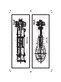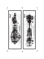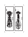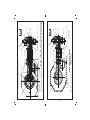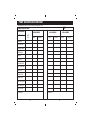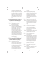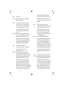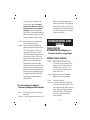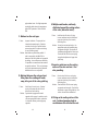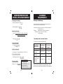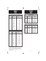
1
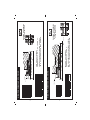
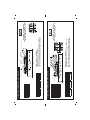
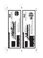
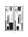
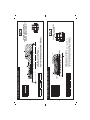
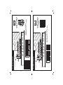
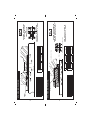
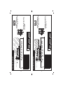
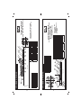
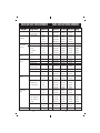
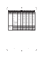
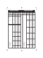
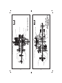
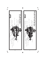
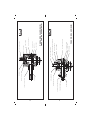
WELL SERVICE PUMP REFERENCE GUIDE
FORT WORTH: 7601 Wyatt Dr. • Fort Worth, Texas 76108 U.S.A
P: 1.800.342.7458 • 817.246.2461 • F: 817.246.6324
HOUSTON: 363 N. Sam Houston Pkwy. E., Suite 1100,
Houston, Texas 77060 • P: 281.820.7807 • F: 281.820.7804
ALICE: 2450 Business Hwy. 281 North • Alice, Texas 78332
P: 361.661.0900 • F: 361.661.0909
BRIGHTON: 7450 Johnson Drive, Suites C & D • Brighton, Colorado 80530
P: 720.494.1805 • F: 720.494.7208
JANE LEW: 7645 Highway 19 North • Jane Lew, West Virginia 26378
P: 304.884.7222 • F: 304.884.7622
LAFAYETTE: 3535 Hwy. 90 East • Lafayette, Louisiana 70518
P: 337.837.3161 • F: 337.837.8171
ODESSA: 2424 E. I-20 • Odessa, Texas 79766
P: 432.580.3887 • F: 432.333.1351
GRANDE PRAIRIE: 104, 11231 - 97 Ave. • Grande Prairie, AB T8V 5N5,
Canada • P: 780.402.3857 • F: 780.402.7081
MEDICINE HAT: 1348 32nd Street S.W. • Medicine Hat, AB T1B 3N7,
Canada • P: 403.504.8353 • F: 403.504.8370
RED DEER: Unit A, 8060 Edgar Industrial Crescent • Red Deer, AB T4P 3R3,
Canada • P: 403.341.3410 • F: 403.341.3072
ABERDEEN: Badentoy Industrial Park, Portlethen • Aberdeen AB12 4YD,
Scotland • P: 44.1224.783666 • F: 44.1224.784184
SINGAPORE: 545 Orchard Road 15-02, Far East Shopping Ctr. • Singapore
238882 • P: 65.6738.3078 • F: 65.6234.2581
DUBAI: Oilfields Supply Center L.T.D. • Building 22, P.O. Box 1518
Jebel Ali, Dubai, U.A.E. • P: 971.4.8836.368 • F: 971.4.8836.485
© 2008 WEIR SPM
WELL SERVICE PUMP REFERENCE GUIDE
WELL SERVICE
PUMP
REFERENCE
GUIDE
CONTENTS
Packing Assembly Drawings & Part Numbers. 3 - 26
High Performance Packing....................... 3 - 14
Standard Packing................................... 15 - 26
Valve & Seat Cross Reference....................... 27 - 31
Plunger Cross Reference............................... 32 - 34
Drawings, Well Service Pumps & Fluid Ends..35 - 50
Pump Maintenance Records......................... 51 - 54
Troubleshooting Guide, Packing................... 55 - 65
Troubleshooting Guide, Plungers.................. 65 - 67
Troubleshooting Guide, Valves & Seats......... 67 - 72
Troubleshooting Guide, Pumps.................... 72 - 77
Routine Preventive Maintenance, Pumps...... 78 - 80
Fluid End Maintenance Procedures............... 82 - 86
Installation Summary.................................... 88 - 90
Safety Guide, Well Service Pumps................. 92 - 99
Application Formulae.........................................100
Clearance Requirements.................................... 101
Torque Tables............................................ 102 -103
Metric Conversions............................................ 105
1
WELL SERVICE PUMP REFERENCE GUIDE
HIGH
PERFORMANCE
PACKING
ASSEMBLY
DRAWINGS
AND
PART NUMBERS
2
3
4
5
1
1
1
1
1
1
1
1
1
1
1
10
3A106990HP
3A106989HP
3A106987HP
3A106986HP
SOFT PKG
SET
3A105323HP
3A105185HP
3A105322HP
3A105315HP
3A105321HP
3A107723HP
COMPLETE
ASSEMBLY
3"
2 3/4"
2 1/2"
2"
SIZE
1
11
1
1
1
1
1
1
3A107007HP
3A107006HP
3A107005HP
3A106994HP
3A106993HP
SOFT PKG
SET
3A105294HP
3A106787HP
3A105228HP
3A105370HP
3A105369HP
COMPLETE
ASSEMBLY
4"
3"
2 1/2"
SIZE
4 1/2"
3 1/2"
PKG ADAPTER
WIPER RING
SPACER
HEADER RING
PRESSURE RING
LANTERN RING
ITEM QTY DESCRIPTION
6
5
4
3
2
1
PKG NUT
3
5
FLUID
CYL NDER
HIGH PERFORMANCE PACKING
3A106988HP
3A106991HP
3A105324HP
4"
3 1/2"
3A106992HP
PKG NUT
PIPE PLUG
3 3/4"
PKG ADAPTER
WIPER RING
BACK-UP
O-RING
BACK-UP
O-RING
HEADER RING
SPACER RING
PRESSURE RING
SEAL RING
LANTERN RING
ITEM QTY DESCRIPTION
11
10
9
8
7
6
5
4
3
2
1
HIGH PERFORMANCE PACKING
4
2
~
8 9
PLUNGER
6 7
WEIR SPM TWS 250
PACKING ASSEMBLIES
6
2
3
4
~
PLUNGER
FOR CO2 SERVICE APPLICATIONS, SPECIFY
“CO2” AT THE END OF EACH PART NUMBER.
SOFT PKG. SET INCLUDES
COMPONENTS #2, 3, 5 AND 6.
1
WEIR SPM TWS 400
or GEOQUIP LC350
PACKING ASSEMBLIES
FOR CO2 SERVICE APPLICATIONS, SPECIFY
“CO2” AT THE END OF EACH PART NUMBER.
SOFT PKG. SET INCLUDES
COMPONENTS #3, 5, 6, 7, 8, 9, 10 AND 11.
5
FLUID
CYLINDER
6
7
1
1
1
1
1
1
3A107000HP
3A106999HP
3A106998HP
SOFT PKG
SET
3A103793HP
3A103792HP
3A105024HP
COMPLETE
ASSEMBLY
2 3/4"
SIZE
3A107011HP
3A107010HP
3A107009HP
3A107044HP
SOFT PKG
SET
3A105368HP
3A104769HP
3A105154HP
3A104731HP
COMPLETE
ASSEMBLY
3"
2 3/4"
2 1/2"
SIZE
3A107008HP
3A107012HP
3A104227HP
1
3A105297HP
10
4"
PACKING
NUT
PIPE PLUG
3 1/2"
4 1/2"
1
1
1
1
1
1
1
1
1
1
WIPER RING
BACK-UP
O-RING
BACK-UP
O-RING
HEADER RING
PKG ADAPTER
PRESSURE RING
SEAL RING
LANTERN RING
ITEM QTY DESCRIPTION
10
9
8
7
6
5
4
3
2
1
4
3
HIGH PERFORMANCE PACKING
3A107001HP
3A103794HP
4"
3 1/2"
4 1/2"
SPACER RING
PKG ADAPTER
SPACER
HEADER RING
PRESSURE RING
LANTERN RING
ITEM QTY DESCRIPTION
6
5
4
3
2
1
PACKING NUT
HIGH PERFORMANCE PACKING
1
5
5
2
PLUNGER
3
6
4
PACKING ASSEMBLIES
6 7
PLUNGER
8 9
PACKING ASSEMBLIES
WEIR SPM TWS 600 SHORT
2-1/2” - 4-1/2”
FOR CO2 SERVICE APPLICATIONS, SPECIFY
“CO2” AT THE END OF EACH PART NUMBER.
SOFT PKG. SET INCLUDES
COMPONENTS #3, 4, 5, 6, 7, 8, 9 AND 10.
2
FLU D
CYL NDER
FOR CO2 SERVICE APPLICATIONS, SPECIFY
“CO2” AT THE END OF EACH PART NUMBER.
WEIR SPM TWS 500LW (H/V)
ROUGH RIDER 500 (H/V)
PACKING NUT SEAL
SOFT PKG. SET INCLUDES
COMPONENTS #2, 3 AND 5.
~
FLUID
CYLINDER
8
9
1
1
1
1
1
1
1
1
3A107007HP
3A107006HP
3A107005HP
3A107004HP
3A107003HP
3A107002HP
SOFT PKG
SET
3A105263HP
3A105262HP
3A104586HP
3A105225HP
3A104703HP
3A104744HP
COMPLETE
ASSEMBLY
3"
2 3/4"
2 1/2"
SIZE
3A107007HP
3A107013HP
3A107005HP
SOFT PKG
SET
3A105166HP
3A105207HP
COMPLETE
ASSEMBLY
3 3/4"
3 1/2"
SIZE
3A107006HP
3A107014HP
3A105348HP
3A107015HP
3A104755HP
3A104367HP
3A107016HP
3A105372HP
5 3/4”
5 1/2"
3A105180HP
3A107018HP
3A105373HP
4”
3A107019HP
3A105312HP
5”
4 1/2”
3A107020HP
3A105377HP
6”
PACKING
NUT
6
6 3/4”
6 1/2"
1
1
1
1
1
1
1
FLAT ADAPTER
WIPER RING
PKG ADAPTER
SPACER
HEADER RING
PRESSURE RING
LANTERN RING
ITEM QTY DESCRIPTION
7
6
5
4
3
2
1
1
7
6
5
2
3
4
PACKING ASSEMBLIES
WEIR SPM TWS 600
WEIR SPM TWS 500LW (V/V)
UN BLOCK
STYLE
7
5
2
3
~
~
4
PLUNGER
FLU D
CYL NDER
FOR CO2 SERVICE APPLICATIONS, SPECIFY
“CO2” AT THE END OF EACH PART NUMBER.
WEIR SPM TWS 900-QWS 2500
PACKING ASSEMBLIES
FOR CO2 SERVICE APPLICATIONS, SPECIFY
“CO2” AT THE END OF EACH PART NUMBER.
SOFT PKG. SET INCLUDES
COMPONENTS #2, 3, 5 AND 8.
1
FLUID
CYLINDER
SOFT PKG. SET INCLUDES
COMPONENTS #2, 3, 5, AND 6.
8
ORIG NAL
STYLE
HIGH PERFORMANCE PACKING
4 1/2"
4"
PACKING
NUT
3 1/2"
WIPER RING
FLAT ADAPTER
SPACER-LONG
PKG ADAPTER
SPACER-SHORT
HEADER RING
PRESSURE RING
LANTERN RING
ITEM QTY DESCRIPTION
8
7
6
5
4
3
2
1
STUFFING BOX
HIGH PERFORMANCE PACKING
10
11
3A107038HP
3A107005HP
3A107004HP
3A107003HP
SOFT PKG
SET
3A102275HP
3A101251HP
3A101250HP
3A101256HP
3A102274HP
3A101255HP
3A101159HP
3A101254HP
3A101253HP
3A101276HP
3A102273HP
3A102272HP
3A102271HP
COMPLETE
ASSEMBLY
6 1/2"
6"
5 3/4"
5 1/2"
5"
4 1/2"
4"
3 3/4"
3 1/2"
3"
2 3/4"
SIZE
1
1
2
2
1
1
1
1
1
3A107021HP
SOFT PKG
SET
3A106698HP
COMPLETE
ASSEMBLY
SIZE
PIPE PLUG
9
STUFFING BOX
5"
WIPER RING
SPACER
BACK-UP
O-RING
HEADER RING
PKG ADAPTER
PRESSURE RING
SEAL RING
LANTERN RING
ITEM QTY DESCRIPTION
9
8
7
6
5
4
3
2
1
1
HIGH PERFORMANCE PACKING
3A107013HP
3A107006HP
3A107007HP
3A107014HP
3A107015HP
3A107016HP
3A107018HP
3A107019HP
3A107020HP
3A107039HP
3A102276HP
6
7"
PACKING
NUT
7
6 3/4"
7 1/2"
1
1
1
1
1
1
1
O-RING
WIPER RING
PKG ADAPTER
SPACER
HEADER RING
PRESSURE RING
FLAT ADAPTER
ITEM QTY DESCRIPTION
7
6
5
4
3
2
1
HIGH PERFORMANCE PACKING
5
2
3
4
PLUNGER
FLUID
CYLINDER
OPI,
GEOQUIP (GARDNER DENVER)
CMW (WEIR SPM)
OMEGA
PACKING ASSEMBLIES
8
3
5
2
6 7
PLUNGER
FOR CO2 SERVICE APPLICATIONS, SPECIFY
“CO2” AT THE END OF EACH PART NUMBER.
SOFT PKG. SET INCLUDES
COMPONENTS #3, 4, 5, 6, 7 AND 9.
4
FLUID
CYLINDER
WEIR SPM TWS 1250 LW (H/V)
ROUGH RIDER 1000 (H/V)
ROUGH RIDER 1500 (H/V)
PACKING ASSEMBLIES
FOR CO2 SERVICE APPLICATIONS, SPECIFY
“CO2” AT THE END OF EACH PART NUMBER.
SOFT PKG. SET INCLUDES
COMPONENTS #2, 3, 5 ,6 AND 7.
1
12
13
1
2
1
1
1
1
1
6
1
1
1
1
1
1
1
1
1
1
1
3A107028HP
3A107027HP
3A107026HP
SOFT PKG
SET
3A104309HP
3A104308HP
3A104307HP
3A104306HP
COMPLETE
ASSEMBLY
5"
4"
3 1/2"
SIZE
3A107029HP
10
PACKING NUT
4 1/2"
PKG ADAPTER
WIPER RING
BACK-UP
O-RING
BACK-UP
O-RING
HEADER RING
SPACER RING
PRESSURE RING
SEAL RING
LANTERN RING
ITEM QTY DESCRIPTION
11
10
9
8
7
6
5
4
3
2
1
1
HIGH PERFORMANCE PACKING
3A107024HP
SOFT PKG
SET
3A102499HP
COMPLETE
ASSEMBLY
SIZE
3A107025HP
3 3/4"
~
3A102136HP
PLUNGER
PACK NG NUT
4"
SPACER
SPACER-LONG
PKG ADAPTER
SPACER-SHORT
HEADER RING
PRESSURE RING
LANTERN RING
ITEM QTY DESCRIPTION
7
6
5
4
3
2
1
HIGH PERFORMANCE PACKING
11
1
7
5
2
3
6
4
FLU D
CYL NDER
PACKING ASSEMBLIES
WEIR SPM TWS 1250LW (V/V)
ROUGH RIDER 1000 (V/V)
ROUGH RIDER 1500 (V/V)
5
4
2
~
6 7
PLUNGER
8 9
FOR CO2 SERVICE APPLICATIONS, SPECIFY
“CO2” AT THE END OF EACH PART NUMBER.
BJ PACEMAKER
PACKING ASSEMBLIES
SOFT PKG. SET INCLUDES
COMPONENTS #3, 5, 6, 7, 8, 9, 10 AND 11.
3
FLU D
CYL NDER
FOR CO2 SERVICE APPLICATIONS, SPECIFY
“CO2” AT THE END OF EACH PART NUMBER.
SOFT PKG. SET INCLUDES
COMPONENTS #2, 3, AND 5.
STUFF NG
BOX
STUFF NG BOX SEAL
14
3A108288HP
3A107032HP
SOFT PKG
SET
3A107981HP
3A105358HP
COMPLETE
ASSEMBLY
4 1/2"
SIZE
PACKING
ADJUSTMENT NUT
5"
1
1
1
1
1
1
1
WIPER RING
SPACER
O-RING
HEADER RING
PKG ADAPTER
PRESSURE RING
LANTERN RING
ITEM QTY DESCRIPTION
7
6
5
4
3
2
1
1
5
3
2
4
6
PLUNGER
HALLIBURTON HT-400
PACKING ASSEMBLIES
FOR CO2 SERVICE APPLICATIONS, SPECIFY
“CO2” AT THE END OF EACH PART NUMBER.
SOFT PKG. SET INCLUDES
COMPONENTS #2, 3, 4, 5, AND 7.
7
FLUID
CYLINDER
~
HIGH PERFORMANCE PACKING
WELL SERVICE PUMP REFERENCE GUIDE
~
STANDARD
PACKING
ASSEMBLY
DRAWINGS
AND
PART NUMBERS
15
1
1
1
1
1
1
1
2
1
1
WIPER RING
BACK-UP
O-RING
BACK-UP
O-RING
HEADER RING
SPACER RING
PRESSURE RING
SEAL RING
LANTERN RING
DESCRIPTION
10
PACK NG NUT
P PE PLUG
17
SIZE
2"
2 1/2"
3"
3 1/2"
4"
STANDARD PACKING
ITEM QTY
10
9
8
7
6
5
4
3
2
1
10
PACK NG NUT
P PE PLUG
STANDARD PACKING
RSL/ACID FRAC
CEMENT
1
RSL/ACID FRAC
1
2
3A106987
3A106986
SOFT PKG
SET
3A105321
3A107723
COMPLETE
ASSEMBLY
2"
SIZE
SOFT PKG
SET
COMPLETE
ASSEMBLY
PLUNGER
3A109549
3A109547
3A106989
3A106987
3A106986
3
4
3A105315
3A105315
2 1/2"
6 7
8 9
1
1
1
1
1
1
1
2
1
1
TEM QTY
10
9
8
7
6
5
4
3
2
1
WIPER RING
BACK-UP
O-RING
BACK-UP
O-RING
HEADER RING
SPACER RING
PRESSURE RING
SEAL RING
LANTERN RING
DESCRIPTION
WEIR SPM TWS 250
(CEMENT)
PACKING ASSEMBLIES
SOFT PKG. SET INCLUDES
COMPONENTS #3, 5, 6 ,7, 8 AND 9.
8 9
WEIR SPM TWS 250
PACKING ASSEMBLIES
SOFT PKG. SET INCLUDES
COMPONENTS #3, 5, 6 ,7, 8 AND 9.
6 7
FLUID
CYLINDER
3A106989
3A105322
3"
2 3/4"
3A109548
3A109547
3A109549
3 1/2"
3A105185
3A105323
2
3A105324
4
4"
5
PLUNGER
5
FLUID
CYLINDER
3 3/4"
3
3A105324
3A105185
3A105322
3A105321
3A107723
CEMENT
16
19
PACKING NUT w/ WIPER GROOVE
WIPER RING
SPACER
HEADER RING
PRESSURE RING
LANTERN RING/FEMALE ADAPTER
DESCRIPTION
5
1
2
1
1
1
ITEM QTY
5
4
3
2
1
1
4
SPACER RING
PRESSURE RING (SHORT)
HEADER RING
SPACER
LANTERN RING/FEMALE ADAPTER
DESCRIPTION
PACKING NUT
STANDARD PACKING
ITEM QTY
6 REF
5
1
4
1
3
1
2
3
1
1
REF
6
FLUID
CYLINDER
1
3
PLUNGER
2
3A106993
SOFT PKG
SET
3A105369
COMPLETE
ASSEMBLY
SIZE
WEIR SPM TWS 500LW (H/V) *
ROUGH RIDER 500 (H/V) *
PACKING ASSEMBLIES
SOFT PKG. SET INCLUDES
COMPONENTS #2, 3, AND 5.
WEIR SPM TWS 400
OR
GEOQUIP LC350
PACKING ASSEMBLIES
3A107001
3A107000
3A106999
3A106998
SOFT PKG
SET
3A103794
3A103793
3A103792
3A105024
COMPLETE
ASSEMBLY
4"
2 3/4"
S ZE
4 1/2"
3 1/2"
3A109550
SOFT PKG
SET
COMPLETE
ASSEMBLY
S ZE
SOFT PKG. SET INCLUDES
COMPONENTS #3, AND 4.
HOR ZONTAL VALVE STYLE
3A105349
*
PLUNGER
4 1/2"
5
2
3A106994
3A105370
PACKING NUT SEAL
3A106995
3A105228
3"
3A106996
3A106997
2 1/2"
3 1/2"
3A105294
4
3A106787
3
4"
4 1/2"
FLUID
CYLINDER
RSL/ACID FRAC
STANDARD PACKING
CEMENT
CEMENT
ACID/FRAC
18
1
1
1
1
1
1
3
1
1
1
21
ITEM QTY
1
1
1
1
1
1
1
1
1
1
1
4
3
WIPER RING
BACK-UP
O-RING
BACK-UP
O-RING
HEADER RING
PRESSURE RING - LONG
PRESSURE RING - SHORT
SEAL RING
LANTERN RING/FEMALE ADAPTER
DESCRIPTION
10
PIPE PLUG
PACKING NUT
10
9
8
7
6
5
4
3
2
1
3
BACK-UP
O-RING
BACK-UP
O-RING
WIPER RING
HEADER RING
PRESSURE RING - SHORT
SEAL RING
LANTERN RING/FEMALE ADAPTER
DESCRIPTION
5
STANDARD PACKING
ITEM QTY
9
8
7
6
5
4
3
2
1
PACKING NUT
PIPE PLUG
STANDARD PACKING
4
PLUNGER
5
PLUNGER
2
2
ACID/FRAC
CEMENT
ACID/FRAC
CEMENT
20
SIZE
3A109554
SOFT PKG
SET
3A104227
3A105368
COMPLETE
ASSEMBLY
4"
3 1/2"
S ZE
3A109555
3A105297
4 1/2"
6 7
3A109556
COMPLETE
ASSEMBLY
8 9
3A107044
3A104731
FLUID
CYLINDER
3A107008
SOFT PKG
SET
3A105154
3A107366
3A104769
3"
2 1/2"
8 9
2 3/4"
6 7
FLUID
CYLINDER
SOFT PKG. SET INCLUDES
COMPONENTS #3, 4, 5, 6,
7, 8, 9 AND 10.
WEIR SPM TWS 600 SHORT
3-1/2” - 4-1/2”
PACKING ASSEMBLIES
SOFT PKG. SET INCLUDES
COMPONENTS #3, 4, 5, 6,
7, 8, AND 9.
WEIR SPM TWS 600 SHORT
2-1/2” - 3”
PACKING ASSEMBLIES
23
8
FLUID
CYLINDER
6
** CEMENT SERVICE
* VITON SEALS
5
8 REF
7
1
6
1
5
1
4
1
3
1
2
2
1
1
PLUNGER
4
2
3
3A107005
3A107004
3A107003
3A109553
SOFT PKG
SET
3A104586
3A105225
3A104703
3A104744
COMPLETE
ASSEMBLY
4"
3 1/2"
3"
2 3/4"
2 1/2"
SIZE
2
1
3
3A107018
3A109557
SOFT PKG
SET
3A105373
3A105372
3A104755
3A105180
3A104367
3A105348
3A105166
3A105207
COMPLETE
ASSEMBLY
5 1/2"
5"
4 1/2"
4"
3 3/4"
3 1/2"
SIZE
3A107013
3A109558
3A109559
3A107014
3A107015
3A107016
3A107019
3A105312
3A107020
* 3A109559V
** 3A109560
* 3A107014V
6"
6 1/2"
PACKING ASSEMBLIES
SOFT PKG. SET INCLUDES
COMPONENTS #4, 5, AND 7.
5 3/4"
3A105377
6 3/4"
* 3A104367V
** 3A105733
* 3A105180V
3A107006
3A105262
4 1/2"
5"
4 1/2"
3A107869
3A105263
SIZE
6 3/4"
3A109551
3A106705
WEIR SPM TWS 600
WEIR SPM TWS 500LW (V/V)
PACKING ASSEMBLIES
SOFT PKG. SET
INCLUDES
COMPONENTS #1,
2, AND 6.
WEIR SPM TWS 900, TWS 1000,
TWS 1200, TWS 1300,
TWS 1600, TWS 1800,
TWS 2000,
TWS 2250, QWS 2500
3A109552
SOFT PKG
SET
3A106049
COMPLETE
ASSEMBLY
6
4"
5
FLUID
CYLINDER
3 1/2"
4
PACKING NUT w/ WIPER GROOVE
O-RING
WIPER RING
LANTERN RING
FEMALE ADAPTER
SPACER
PRESSURE RING
HEADER RING
DESCRIPTION
PLUNGER
1
ITEM QTY
7
STANDARD PACKING
PACKING NUT w/ WIPER GROOVE
WIPER RING
SPACER
HEADER RING
PRESSURE RING
FEMALE ADAPTER
FLAT ADAPTER
LANTERN RING
ITEM QTY DESCRIPTION
8 REF
7
1
6
1
5
1
4
2
3
1
2
1
1
1
8
STUFFING BOX
STANDARD PACKING
CEMENT
ACID/FRAC
22
25
REF
1
1
1
1
2
1
1
2
2
1
1
1
1
1
1
ROD WIPER
BACKUP RING
O-RING
SEAL RING
HEADER RING
PRESSURE RING
FEMALE ADAPTER
LANTERN RING
ITEM QTY DESCRIPTION
8
7
6
5
4
3
2
1
8
STUFFING BOX
2
3
PLUNGER
PACKING NUT w/ WIPER GROOVE
O-RING
WIPER RING
FEMALE ADAPTER
SPACER
PRESSURE RING
HEADER RING
DESCRIPTION
STANDARD PACKING
7
6
5
ITEM QTY
7
6
5
4
3
2
1
STANDARD PACKING
4
2
5
*
PACKING ASSEMBLIES
3A109561
SOFT PKG
SET
3A107021
SOFT PKG
SET
3A106702
3A106698
COMPLETE
ASSEMBLY
5"
SIZE
SOFT PKG. SET INCLUDES
COMPONENTS #3, 4, 6, 7, AND 8.
HOR ZONTAL VALVE STYLE
COMPLETE
ASSEMBLY
PLUNGER
SOFT PKG
SET
COMPLETE
ASSEMBLY
SIZE
SOFT PKG. SET
INCLUDES
COMPONENTS #1, 2,
5, AND 6.
WEIR SPM TWS 1250LW (H/V) *
ROUGH RIDER 1000 (H/V) *
ROUGH RIDER 1500 (H/V) *
3A107039
3A107038
3A109573
3A109572
3A109571
3A109570
3A109569
3A109568
3A109567
3A109566
3A109565
3A109564
3A109563
3A109562
3A102276
3A102275
3A101251
3A101250
3A101256
3A102274
3A101255
3A101159
3A101254
3A101253
3A101276
3A102273
3A102272
3A102271
5"
3
PACKING ASSEMBLIES
OPI, GEOQUIP (GARDNER DENVER)
CMW (WEIR SPM)
OMEGA
1300, 1800, 2000
BRAKE HORSE POWER SERIES
7 1/2"
7"
6 3/4"
6 1/2"
6"
5 3/4"
5 1/2"
5"
4 1/2"
4"
3 3/4"
3 1/2"
3"
2 3/4"
SIZE
6 7
1
FLUID CYLINDER
FLUID
CYLINDER
4
CEMENT
ACID
FRAC
24
26
1
2
1
1
1
1
ITEM QTY
6
5
4
3
2
1
SPACER - SHORT
SPACER - LONG
HEADER RING
PRESSURE RING
FEMALE ADAPTER
LANTERN RING
DESCRIPTION
5
1
2
PLUNGER
STUFFING BOX
PACKING NUT
ACID/FRAC
CEMENT
STANDARD PACKING
6
3A107025
3A107024
SOFT PKG
SET
3A102136
3A102499
COMPLETE
SET
SIZE
VALVE OVER VALVE STYLE
5
4"
*
4
3 3/4"
3
FLUID
CYLINDER
PACKING ASSEMBLIES
SOFT PKG. SET INCLUDES
COMPONENTS #3, AND 4.
WEIR SPM TWS 1250LW (V/V) *
ROUGH RIDER 1000 (V/V) *
ROUGH RIDER 1500 (V/V) *
VALVE AND SEAT CROSS REFERENCE
INSERT
VALVE ASSY-UPPER
VALVE SEAT
SEAT SEAL
SUCTION AND DISCHARGE
VALVE ASSEMBLY
27
VALVE AND SEAT CROSS REFERENCE
Pump Mfr.
BJ Services
CMW
Pump Model
(Geoquip)
P105800
P105801
2P110363
*
Pacemaker, (Discharge)
3"-5"
2A109538PP
2A109542
2P110357
*
Clarksville, 1300HP
3.75"-4"
2A109538PP
2A109542
2P110357
*
4.50"-5"
2A109539PP
2A109543
2P110363
*
5.50"-6"
2A109540PP
2A109544
2P110359
*
6.50"-7.50"
2A109627PP
2A109621
2P110360
*
LC-350, H-600
3.50"-4.50"
2A109537PP
2A109541
2P110356
4P100198
H-880
3.50"-4"
2A109538PP
2A109542
2P110357
*
H-1600
4.50"-5"
2A109539PP
2A109543
2P110363
4P100348
C-1300,1800
5.50"-6"
2A109540PP
2A109544
2P110359
4P106813
J-2000
6.50"-7.50"
2A109627PP
2A109621
2P110360
4P100281
GT-78-1000
4"-5.25"
2A109538PP
2A109542
2P110363
*
5.50"-7.50”
2A109540PP
2A109544
2P110359
*
P105740
P105750
P105760
4P102383
346P, 46P, 326P
SA-625, -626,-630,-634-5
2A109608PP
2A109605
2P110355
4P102383
SA-640-5,SA-650-L
2A109538PP
2A109542
2P110357
*
2A109539PP
P105802
2P110363
*
SB-644-5,SA-644-5,-10
SA650-5,-10,SB-650-5
2A109627PP
2A109621
2P110360
*
3.50"-4"
2A109537PP
2A109541
2P110356
*
4.50"-5"
2A109539PP
2A109541
2P110363
*
4"-5.25”
2A109539PP
2A109541
2P110363
*
5.50"-7.50"
2A109540PP
2A109544
2P110359
*
1300-1800HP
3.75"-4"
2A109538PP
2A109542
2P110357
*
MW/MWA Fluid End
4.50"-5"
2A109539PP
2A109543
2P110363
*
W-1300,-1800,-2000
5.50"-6"
2A109540PP
2A109544
2P110359
*
6 .50"-7.50"
2A109627PP
2A109621
2P110360
*
2.75"-3"
2A109608PP
2A109605
2P110355
*
3.50"-4"
2A109537PP
2A109541
2P110356
*
4.50"-5"
2A109539PP
2A109543
2P110363
*
880 AWS, 1600 BWS
3.50"-4"
2A109538PP
2A109542
2P110357
*
1000-1300-1800 AWS
4.50”-5"
2A109539PP
2A109543
2P110363
4P100235
1300-1800-2000 CWS
5.50"-6"
2A109540PP
2A109544
2P110359
4P106813
GD-2000
6.50"-7.50"
2A109627PP
2A109621
2P110360
4P100281
1000-1300WS
4"-5.25"
2A109539PP
2A109621
2P110363
*
5.50"-7.50”
2A109540PP
2A109544
2P110359
*
2A109539PP
2A109544
2P110363
*
Super 48,S-824,SA-824
W-350, W-500
Omega
Gardner Denver
1000-1300HP
350-500 AWS
(OPI)
Pinion
Continued on Page 30
Seat Part No. Insert Part No. Spring
3"-5"
Gist
Oilwell
Valve Part No.
Pacemaker, (Suction)
(WEIR SPM)
Gardner Denver
Plunger Size
VALVE AND SEAT CROSS REFERENCE
RB-5, RB-6
28
29
* Call Weir SPM for information
VALVE AND SEAT CROSS REFERENCE
Pump Mfr.
Weir SPM
Pump Model
TWS 250
TWS 400
TWS 500LW-600
TWS 600S
Western
(Rough Rider)
TWS 900
TWS 1250LW
TWS 1300-1600-1800-20002250; QWS 2000-2500LW
TWS 1600LW; QWS 20002500LW
QWS 2000-2500LW
RB-80, RB-81
RR500 Mono Block F.E.
RR1000 Mono Block F.E. VDV
Rough Rider (RR) 1500 VDV
RR1000 MONOBLOCK HV
Plunger Size
1.75"-3"
3.25"-4"
2 .50"-3"
3 .50"-4 .50”
2 .75"
3"-4 .75"
2 .50"-3"
3.50"-4 .50"
3.50"-4"
4"
4.50"-5”
5.50"-6"
6.50"-7.50"
4"
4.50"-5"
5"
VALVE AND SEAT CROSS REFERENCE
Valve Part No. Seat Part No. Insert Part No.
Spring
2A109608PP
2A109537PP
2A109608PP
2A109537PP
2A109608PP
2A109537PP
2A109608PP
2A109537PP
2A109538PP
P105740
2A109539PP
2A109539PP
2A109540PP
2A109605
2A109541
2A109605
2A109541
2A109605
2A109541
2A109605
2A109541
2A109542
P105750
2A109543
2A109543
2A109544
2P110355
2P110356
2P110355
2P110356
2P110355
2P110356
2P110355
2P110356
2P110357
P105760
2P110363
2P110363
2P110359
4P101362
4P100198
4P101362
4P100198
4P101362
4P100198
4P101634
4P100198
4P100338
4P101860
4P100348
4P100235
4P100116
2A109627PP
P105740
2A109537PP
P105740
2A109539PP
2A109539PP
2A109621
2A109543
2A109541
P105750
2A109543
2A109543
2P110360
2P110363
2P110356
P105760
2P110363
2P110363
4P10028
*
*
4P102062
4P102062
P101860
* Call Weir SPM for information
30
31
PLUNGERS CROSS REFERENCE
Pump
Manufacturer
CMW
(Weir SPM)
GARDNER DENVER
(OPI)
OMEGA
OPI, OMEGA
OILWELL
Weir SPM
Pump
Model
1300
1300 THRU 2000
500
SA640
TWS 250
TWS 400
TWS 600
TWS 600S
• Specify Standard
16” Length
• Specify Optional
18” Length
• Specify Optional
21” Length
TWS 900
32
Plunger Plunger
Size
Part No.
6.75" SHORT
6.75" STD.
4.00"
4.50"
5.00"
5.75"
6.50"
2.75"
3.00”
3.50"
4.00"
4.50"
5.00"
4.00"
1.75"
2.00"
2.25"
2.50"
2.75"
3.00"
3.25"
3.50"
3.75"
4.00"
2.50"
2.75"
3.00"
3.50"
4.00"
4.50"
2.50"
2.75"
3.00"
3.50"
4.00"
4.50"
2.00"
2.50"
2.75"
3.00”
3.50"
4.00"
4.50"
3.50”
2P102401
3P101432
3P103963
3P103950
3P100233
3P108327
3P100258
3P107300
3P107301
3P107302
3P107303
3P107304
3P107305
2P102998
3P104545
3P104546
3P104547
3P103501
3P103502
3P103503
3P103504
3P103505
3P103506
3P103507
3P101397
3P101385
3P101384
3P100968
3P101334
3P100853
3P104740
3P101733
3P100325
3P100293
3P100813
3P100181
2P106313
2P104716
2P104717
2P103345
2P103344
2P103313
2P103312
3P105202
PLUNGERS CROSS REFERENCE
Pump
Manufacturer
Weir SPM
Pump
Model
OPI880
TWS 1000 LW
TWS 1300
TWS 1600
TWS 1800
TWS 2000
• Specify Standard
16” Length
• Specify Optional
18” Length
• Specify Optional
21” Length
TWS2250
33
Plunger Plunger
Size
Part No.
3.75"
4.00"
4.50"
5.00"
5.50"
5.75"
6.00”
3.75"
4.00"
4.50"
5.00"
5.50"
5.75"
6.00"
6.50"
6.75"
3.50"
3.75"
4.00"
4.50"
5.00"
5.50"
5.75"
6.00"
3.75"
4.00"
4.50"
5.00"
5.50"
5.75"
6.00"
6.50"
3.75"
4.00"
4.50"
5.00"
5.50"
5.75"
6.00"
6.50"
3.75"
4.00"
4.50"
5.00"
5.50"
3P104144
3P100772
3P100725
3P100366
3P107060
3P107061
3P107062
3P103887
3P100339
3P100654
3P100233
3P107060
3P107061
3P107062
3P100258
3P101407
3P105202
3P104144
3P100339
3P100725
3P100366
3P101423
3P101652
3P101424
3P103887
3P100339
3P100654
3P100233
3P107060
3P107061
3P107062
3P100258
3P103887
3P100339
3P100654
3P100233
3P107060
3P107061
3P107062
3P100258
3P103887
3P100339
3P100654
3P100233
3P100136
PLUNGERS CROSS REFERENCE
Pump
Manufacturer
Weir SPM
Pump
Model
TWS 2250
QWS-2000-2500
WESTERN ROUGH
RIDER
500 HV MONO
TWS 500LW
Weir SPM
500 SECT
500 HV SEC*
1000 HV MONO
TWS 1000/1250
1000 VOV MONO
TWS 1000/1250
1500 VOV MONO
* SEC
Sectional Style
34
Plunger Plunger
Size
Part No.
5.50"
5.75"
6.00"
6.50"
3.75"
4.00"
4.50"
5.00"
5.50"
5.75"
6.00"
6.50"
2.75"
3.00"
3.50"
4.00"
4.50"
4.50"
3.75"
4.00"
3P107060
3P107061
3P107062
3P100258
3P103887
3P100339
3P100654
3P100233
3P107060
3P107061
3P107062
3P100258
2P105019
2P18196
1P101925
1P103772
1P101969
1P102014
2P102527
1P102167
5.00"
5.75"
3.75"
4.00"
5.00”
5.75"
1P102169
2P102728
2P102489
1P102037
2P102075
2P102602
WELL SERVICE PUMP REFERENCE GUIDE
WELL SERVICE
PUMP
AND
FLUID END
DRAWINGS
35
36
37
3" NPT POWER END
LUBE DRAIN
FRAME
3"NPT POWER END
LUBE DRAIN
FRAME
CROSSHEAD
PLUNGER
TWS 250
(THB 175)
WRIST PIN
PACKING
PONY ROD CLAMP
COVER
4" VICTAULIC SUCTION
FLUID CYLINDER
POWER END
CRANK SHAFT
PONY ROD CLAMP
PLUNGER
PONY ROD
WRIST PIN
TWS 400
(THB 225)
CROSSHEAD
CONNECTING ROD
4" VICTAULIC SUCTION
PACKING
FLUID CYLINDER
COMPONENT PARTS CAN BE ORDERED BY CONTACT NG WE R SPM.
POWER END
CRANK SHAFT
CONNECTING ROD
PONY ROD
COMPONENT PARTS CAN BE ORDERED BY CONTACT NG WE R SPM.
FLU D END
FLU D END
VALVING
VALVE
STOP
COVER
VALVING
COVER
VALVING
VALVE
STOP
COVER
VALVING
38
39
FRAME
PACKING
FLUID CYLINDER
PLUNGER
PONY ROD CLAMP
WRIST PIN
PACKING
5" VICTAULIC SUCTION
PONY ROD
TWS 600 (THB 350)
CONNECTING ROD
FLUID CYLINDER
FLUID END
NATIONAL OILWELL SA640 Parts Also Available
POWER END
3" NPT POWER END
LUBE DRAIN
CRANK SHAFT
VALVING
4" VICTAULIC SUCTION
COVER
VALVING
VALVE
STOP
COVER
VALVING
COVER
VALVING
HOR ZONTAL VALVE
FLU D END
VALVE
STOP
COVER
ALSO AVA LABLE W TH VALVE OVER VALVE FLU D CYL NDER
TWS 500LW
ROUGH RIDER 500
PLUNGER
CROSSHEAD
WRIST PIN
CONNECTING ROD
COMPONENT PARTS CAN BE ORDERED BY CONTACT NG WE R SPM.
POWER END
3" SCH 40 STRAIGHT PIPE
POWER END LUBE DRAIN
FRAME
CRANK SHAFT
COMPONENT PARTS CAN BE ORDERED BY CONTACT NG WE R SPM.
40
41
3" NPT POWER END
LUBE DRAIN
FRAME
CROSSHEAD
COVER
4" VICTAULIC SUCTION
TWS 600S
(THB 300S)
QWS 1000S
WRIST PIN
CONNECTING ROD
PACKING
FLUID CYLINDER
FLU D END
CONNECTING ROD
PLUNGER
FLUID END
COVER
4" VICTAULIC SUCTION
PACKING
TWS 900
(THB 550)
WRIST PIN
CROSSHEAD
PONY ROD CLAMP
PONY ROD
FLUID CYLINDER
COMPONENT PARTS CAN BE ORDERED BY CONTACT NG WE R SPM.
POWER END
POWER END
CRANK SHAFT
3" NPT POWER END
LUBE DRAIN
FRAME
1/2" NPT POWER END
LUBE FEED
CRANK SHAFT
COMPONENT PARTS CAN BE ORDERED BY CONTACT NG WE R SPM.
VALVING
VALVE
STOP
COVER
VALVING
VALVING
VALVE
STOP
COVER
VALVING
42
43
CRANK SHAFT
PACKING
PONY ROD CLAMP
PONY ROD
CROSSHEAD
WRIST PIN
CONNECTING ROD
FLUID CYLINDER
COVER
PLUNGER
COMPONENT PARTS CAN BE ORDERED BY CONTACTING WEIR SPM.
QWS 2500 style pumps
(QHB 1575)
Material & sizes may vary.
POWER END
5" VICTAULIC SUCTION
VALVING
VALVE
STOP
COVER
VALVING
TWS 1300 / 1600 / 1800 / 2000 / 2250 style pumps(THB 1050)
FLUID END
PLUNGER
PONY ROD
PONY ROD CLAMP
PACKING
FLUID CYLINDER
COVER
FLUID END
6" VICTAULIC SUCTION
VALVING
VALVE
STOP
COVER
VALVING
Parts for CMW, OPI, Gardner Denver, Geoquip, Omega Also Available
3" NPT POWER END
LUBE DRAIN
WRIST PIN
CROSSHEAD
CONNECTING ROD
Material & sizes may vary.
POWER END
FRAME
FRAME
CRANK SHAFT
COMPONENT PARTS CAN BE ORDERED BY CONTACTING WEIR SPM.
44
45
PLUNGER
STUD
STUFFING BOX
~
FLUID CYLINDER
FLUID CYLINDER
PLUNGER
DIAPHRAM
PLUNGER
PLUNGER CLAMP
PACKING NUT
GAUGE CONNECTION
6.00
STROKE
(.88)
6" STROKE
.25
TWS 400 FLUID END
VALVE SPRING
VALVE STOP
SUCTION COVER
VALVE STOP
VALVE
SPRING
TWS 500LW
ROUGH RIDER 500
HORIZONTAL VALVE
FLUID END
VALVE SPRING
DISCHARGE COVER
(1.96)
VALVE SPRING
DISCHARGE COVER
46
47
PACKING NUT-GROOVED
STUFFING BOX
PACKING NUT-GROOVED
PACKING GLAND
PLUNGER
PLUNGER CLAMP
RETAINER NUT
DISCHARGE COVER
PLUNGER
PLUNGER CLAMP
RETAINER NUT
DISCHARGE COVER
TWS 500, TWS 600 UNIBLOCK
VALVE-OVER-VALVE FLUID END
VALVE SPRING
VALVE STOP
SUCTION COVER
SUCTION COVER NUT
VALVE SPRING
FLUID CYLINDER
GAUGE CONNECTION
TWS 500, TWS 600,
ROUGH RIDER 500
VALVE OVER VALVE FLUID END
VALVE SPRING
VALVE STOP
SUCTION COVER
SUCTION COVER NUT
VALVE SPRING
FLUID CYLINDER
GAUGE CONNECTION
48
49
PLUNGER
PLUNGER CLAMP
PACKING NUT-GROOVED
DISCHARGE COVER
RETAINER NUT
PLUNGER
PACKING NUT-GROOVED
DISCHARGE COVER
RETAINER NUT
VALVE SPRING
TWS 900 FLUID END
VALVE STOP
SUCTION COVER
SUCTION COVER NUT
VALVE SPRING
FLUID CYLINDER
GAUGE CONNECTION RETAINER NUT
GAUGE CONNECTION
TWS 600S FLUID END
QWS 1000S FLUID END
VALVE SPRING
VALVE STOP
SUCTION COVER
SUCTION COVER NUT
FLUID CYLINDER
VALVE SPRING
GAUGE CONNECTION
50
QUINTUPLEX HAS FIVE CYLINDERS
PLUNGER
PLUNGER CLAMP
PACKING NUT-GROOVED
DISCHARGE COVER
RETAINER NUT
TWS 1300-2250, QWS 2000 - 2500
FLUID END
VALVE SPRING
VALVE STOP
SUCTION COVER
SUCTION COVER NUT
VALVE SPRING
FLUID CYLINDER
GAUGE CONNECTION RETAINER NUT
GAUGE CONNECTION
WELL SERVICE PUMP REFERENCE GUIDE
PUMP
MAINTENANCE
RECORDS
51
PUMP MAINTENANCE RECORD
MAINTENANCE LOGS ALSO AVAILABLE FROM WEIR SPM
UNIT
NO.
PUMP DESCRIPTION:
HORSEPOWER
SERIAL NO.
REPLACEMENT
PART
NO.
DATE
HOURS
REPLACEMENT
REPLACEMENT
DATE
HOURS
DATE
PLUNGER
HEADER RING
PRESSURE RING
WIPER RING
SPACER
ADAPTER
LANTERN RING
SUCTION VALVE
DIS VALVE
INSERT (SUC)
INSERT (DIS)
SEAT (SUCTION)
SEAT (DISCHG.)
VALVE SPRING
COMMENTS:
COMMENTS:
52
53
HOURS
WELL SERVICE PUMP REFERENCE GUIDE
TROUBLESHOOTING
GUIDE
PACKING, PLUNGERS,
VALVES & SEATS,
AND
WELL SERVICE PUMPS
54
55
TROUBLESHOOTING GUIDE
PACKING
TROUBLE SYMPTOM:
A. Significant leakage upon immediate
startup with priming of the pump on
individual or all plungers.
Appearance of packing new or unused.
PROBABLE CAUSE & SOLUTION:
1. Cause:
Packing in backward.
Solution: Remove packing. Make sure the seal rings
and packing assembly are installed correctly
with V of the seal rings facing the internal
chamber of the cylinder.
2. Cause:
Incorrect size packing.
Solution: Remove packing and check with plunger for
fit. Packing should be snug to tight on the
plunger. Verify that the packing size is
correct. Contact Weir SPM for any possible
size problems.
3. Cause:
Incorrect adjustment.
Solution: Follow instructions for proper adjustment.
4. Cause:
Incorrect length of packing assembly.
Solution: Remove packing. Review drawings and
dimensions of packing assembly and
stuffing box to assure that proper
adjustment can be accomplished within the
available envelope.
56
5. Cause:
Packing very cold or frozen. Packing may be
broken or deformed.
Solution: Remove and replace packing assemblies.
Prime pump with warm fluid (water, oil etc.)
and run pump until fluid cylinders are warm
throughout. If possible, warm pump fluid
cylinders with air blowers or heaters before
commencing pumping operations.
6. Cause:
Plunger settles on the side of the packing
during transport and causes deformation.
Solution: Remove and replace packing assemblies.
B. Packing running very hot immediately
upon start of pumping. Individual or
all plungers.
1. Cause:
Fluid cylinder not filled or pump not properly
primed. Packing appears burned or
scorched. Some deformation of seal rings
and brass will have black or dark streaks
across the I.D.
Solution: Remove and replace packing. Make sure
that all cylinders are fully primed. Check all
valves to make sure they are not stuck and
operate properly. Run pump slowly until it is
fully primed and operable.
2. Cause:
Metal components in packing assembly
incorrect size or eccentric. Some metal parts
will have discolored or burned streaks across
the I.D.
Solution: Remove packing assembly and check with
57
micrometer for proper size. If micrometer is
not available check brass metal rings over the
plunger for proper fit both for size and
eccentricity (egg shaped). Never reuse
eccentric metal or brass rings. Metal rings
should slide freely over the full length of the
plunger. Check the plunger for over-size
dimension and for "roundness". Check
plunger for possible tapering caused by
improper grinding of surface.
C. Packing becomes very hot immediately
after the pump reaches running
pressure. Individual or all Plungers.
1. Cause:
Insufficient packing lubrication.
Solution: Check lubrication reservoir to verify that it is
full and the system is operating properly at
all plungers. Make sure to use the proper
and recommended lubricating oil in
sufficient amounts. Larger plungers take
more lubricant than small plungers.
2. Cause:
Discharge valve stuck open or washed out.
This allows discharge pressure to stay on
the packing at all times, limiting the
packing's ability to relax and become
lubricated. This can happen at any time
during pumping.
Solution: Replace with a good discharge valve.
Replace packing assembly with new set.
3. Cause:
Misalignment due to "burrs" on the mating
faces of the pony rod and/or plunger.
Solution: Visually inspect whether the connection is
58
aligned. Remove plunger from pony rod and
check both surfaces for irregularities. If
plunger has been resurfaced, or refurbished,
check for "squareness" or whether its mating
surface is perpendicular to the barrel.
4. Cause:
Packing too loose, letting fluid into the voids
of the packing causing hydrostatic pressures
in excess of operating pressure. Prevalent in
multiple ring sets.
Solution: Check with Weir SPM for proper adjustment
instructions.
5. Cause:
Very rough plunger surfaces.
Solution: Remove plunger and check finish. Surface
should be extremely smooth without
grooves, nicks, or scratches. Some feel that
an RMS finish of 4 to 5 will be too smooth for
lubricant to provide a satisfactory film thus
causing heat. A finish above 16 RMS will
cause excessive packing wear and heat.
6. Cause:
Improper filling of the pump cylinders
causing cavitation.
Solution: Make sure the pump is operating properly
with adequate supercharging. High viscosity
fluids or high pump speeds can cause
problems. It may be necessary to slow pump
or to increase charge pump pressure.
7. Cause:
Hot fluids being pumped. Packing will
appear hard and brittle. Potential for I.D. of
packing rings to break and slough off.
Solution: Check with Weir SPM on the high temperature limits of the packing components.
Standard acrylonitrile (Buna N) cotton/nylon
59
composition rings will deteriorate in fluids
above 200°F. The temperature in the stuffing
box will be much higher due to the additional
sliding friction. It may be necessary to use a
higher temperature elastomer such as HNBR;
or a fluoroelastomer such as Viton, Fluorel or
Aflas.
D. Packing running hot after 1 to 2 hours of
of operation. All or individual plungers.
1. Cause:
Fluid being pumped is corrosive and
attacking the packing materials.
Solution: Determine the exact makeup and
composition of the fluid being pumped and
the packing material. Contact Weir SPM for
material compatibility. Some common
fluids such as #1 diesel, toluene, zylene,
over 15% HCL, synthetic gels, kerosene, and
naphtha will present problems for low-tomedium acrylonitrile (Buna N) pressure rings.
It may be necessary to replace packing rings
with a ring molded from a more corrosion or
heat resistant material.
E. Short or unacceptable life during normal
operations. Individual or all plungers.
1. Cause:
Damaged header ring from lack of
lubrication at startup. Insufficient lubrication
at startup can cause the header ring to stick
to the plunger causing tearing during the first
stroke. This problem has the greatest
potential when the pump has been idle and
any residual plunger lube has drained from
60
the surfaces.
Solution: Replace damaged packing and adjust
packing lube. Lubrication should flow freely
to plunger prior to stroking the pump.
Although conditions will vary, generally
twenty (20) drops per minute lube oil rate is
recommended.
2. Cause:
Plunger lubrication system running out of oil.
Solution: Keep lubrication reservoir supplied with oil at
all times and fully operational. Put an alarm
on the device to announce low lubrication
supply.
3. Cause:
Low suction pressure or inadequate fluid
volume to the pump during changeovers
from one tank to another. This allows pump
to run dry and cavitate.
Solution: Plan pumping operations to allow for smooth
changeovers during course of the job.
4. Cause:
Abrasives causing plunger scoring or
excessive plunger wear.
Solution: Review packing assembly. Consult with Weir
SPM for best assembly for abrasive materials.
Scoring can result from large dry particles of
material from previous jobs breaking off the
equipment and going through the pump.
Attention should be given to cleaning the
equipment "well" after each job.
5. Cause:
Oversized, egged, or worn brass of metal
components.
Solution: Replace all worn or oversized brass or metal
components. Discard the old parts
immediately.
61
based metals look alike. Generally, the
higher strength bronze should be used.
Standard brass should not be used. It may
be necessary to use stainless steel or other
material.
6. Cause:
Worn Plungers.
Solution: Remove and replace worn-out plungers.
Discard worn plungers.
7. Cause:
Worn or grooved stuffing boxes. Stuffing
boxes will also wear out, although usually
slower than plungers. With stuffing boxes,
the wear appears as grooves in the I.D. The
deepest groove will be adjacent to the last
ring in the stuffing box (ring farthest from
pressure).
Solution: Remove and replace stuffing box with a new
or rebuilt unit. If stuffing boxes are to be
rebuilt, they should be returned to the
manufacturer. Extreme care and attention
should be given to assuring the surfaces are
smooth, parallel and perpendicular to the
gland and bottom of the stuffing box.
8. Cause:
Corrosive attack on metal or brass
components in all cylinders. The metal will
appear black, charred, blue, brittle or
otherwise deformed.
Solution: Determine the exact composition and
chemical makeup of the material being
pumped. Higher or stronger concentrations
of fluids being pumped will cause greater
damage than lower strength materials.
Check with Weir SPM and compatibility
charts. Close attention should be given to
strength and concentration of materials.
Replace all components with a satisfactory
material. Check with Weir SPM regarding the
metal components. Determine the suitability
of the material being used. Many brass
62
9. Cause:
Excessive plunger wear during a job.
Plunger will appear dull gray in color or show
excessive streaks and scoring. A dull gray
rough appearance is generally caused by
caustic material attack. Excessive streaks
and scoring can occur on hardened steel
plungers (not coated) due to oxidizing (rust)
while sitting between jobs.
Solution: Check with Weir SPM regarding the
plungers to determine the specifications on
the matrix of the spray metal plunger. It
may be necessary to change surface
materials. Check with compatibility charts
for suitable matrix materials. For standard
hardened steel plungers, it will be necessary
to remove them from the pump between
jobs and coat them with a heavy grease or
cosmoline to keep rust from attacking
them.
10. Cause: Loose gland and subsequent loose packing.
Solution: When using a spring loaded or header ring
packing assembly, the gland should be
tightened as tight as possible since it is a
metal-to-metal assembly. Occasionally due
to vibration or other factors, the gland will
loosen. It is a good practice to check the
glands for tightness before each job. For
adjustable packing assemblies, the adjustment should be made while the pump
63
blown, check the packing lube pressure. It
should not exceed 30 psi. The packing lube
system should have a 30 psi relief valve, if it
is equipped with an air powered lube pump.
If it is an air over oil system, the air regulator
should not exceed 30 psi.
is running. Tighten with spanner or bar
furnished with the pump. Use trained
personnel only. Make sure to take all
safety precautions and use complete
safety gear. Experience will govern how
tight is correct. On adjustable assemblies, the
gland has a tendency to loosen so the gland
should be checked at least once an hour.
11. Cause:
Broken spring from a spring loaded packing
assembly, causing plunger scoring.
Solution: There is too much friction between the
packing and plunger causing the packing to
"stick" to the plunger, thus crushing or
compressing the spring on every stroke.
This chucking motion will fatigue the spring
wire and cause it to break. There is then
danger that the loose spring will score the
plunger. Remove packing and plunger.
Replace with new plunger and packing
assembly. Determine the cause of the rough
plunger and if there is any softening of the
packing from the fluid being pumped. Also
make sure lubricator is operating properly. If
this happens often, check with Weir SPM
regarding plunger surface material and
packing selection.
F. Excessive leakage of packing oil
between the plunger and the rod wiper.
1. Cause:
Worn or blown rod wiper. Excessive packing
lube pressure.
Solution: If it is worn, replace the rod wiper ring. If it is
64
TROUBLESHOOTING GUIDE
PLUNGER
TROUBLE SYMPTOM:
A. Extreme wear on stuffing brass, or
brass worn eccentric, or egg shaped.
PROBABLE CAUSE & SOLUTION:
1. Cause:
Incorrect dimensions on brass. The brass
I.D. is too large, letting the packing push the
plunger to one side. This allows the packing
to extrude through the open side. It also
allows the plunger to rub against the brass,
causing eccentric wear.
Solution: Remove brass and discard immediately.
Replace brass with correct dimensions.
2. Cause:
Incorrect "brass" materials.
Solution: It is difficult to determine the difference in
"brass" metals with a visual inspection. The
correct material must be used for satisfactory
service. Replace with higher grade bronze.
Check with Weir SPM. Commercial brass,
660C brass or similar material will not
perform satisfactory.
65
3. Cause:
Misalignment.
Solution: Check alignment of crosshead to end of the
plunger. Especially check connection
between crosshead and pony rod. Inspect
threads or clamp ends on the plunger (as it
attaches to the pony rod) for burrs, crossthreading or any aggravating factors.
Remove burrs or replace non-conforming
component.
4. Cause:
Plunger ground eccentric or tapered.
Solution: Remove plunger from pump and check for
roundness and for taper. This can be done
by rolling on a "flat" surface. If eccentric, the
plunger will "jump" or not roll evenly on the
surface. If the plunger is tapered it will roll in
a circle with the small end toward the center
of the circle. Replace with correct plunger.
5. Cause:
Plunger is hollow with insufficient barrel wall
thickness to hold shape at pumping pressures.
Indications will reflect an hourglass shape to the
plunger and possible eccentric wear on the
brass.
Solution: Check on the maximum pressure allowed per
plunger size.
6. Cause:
Large heavy plunger causing it to ride on the
bottom of the packing/brass assembly.
Solution: Check on an alternate packing with more
metal support in the packing/brass or on a
lighter weight hollow plunger.
7. Cause:
Brass O.D. too small or the stuffing box I.D. is
worn or machined too large. This lets the I.D.
of the brass rings ride on the plunger and
66
does not support the plunger or packing.
Solution: Disassemble pump and measure the I.D. of
the stuffing box. Check the O.D. of the
brass rings for correct dimensions. Check
with manufacturer for correct dimensions on
the brass and stuffing box.
8. Cause:
Pump has been idle for a long period. The
weight of the plunger has caused it to distort
the packing and contact the brass.
Solution: Replace packing and brass.
TROUBLESHOOTING GUIDE
VALVES AND SEATS
TROUBLE SYMPTOM:
A. Eroded Insert
PROBABLE CAUSE & SOLUTION
1. Cause: Chemical attack on the insert, usually acid.
Solution: Determine the exact makeup of the fluid
being pumped. Various elastomers are
available that will perform in specific well
service fluids. It may involve higher
acrylonitrile rubber content or better
polyurethane materials.
B. Swollen Valve Inserts
1. Cause:
Pumped fluid contains a high aromatic, low
aniline solvent.
Solution: Determine the exact makeup of the fluid
being pumped. Use high quality
67
polyurethane inserts. Use high temperature
acrylonitrile rubber inserts for temperatures
above 200°F operations. Check with Weir
SPM.
C. Washout on the seat taper.
1. Cause:
Improper installation. The pump deck not
cleaned and prepared properly. Probably a
metal burr or some type of particle between
seat and pump deck in the taper not allowing
the seat to bottom properly.
Solution: Hand deburr or polish where possible. If
wash is severe check with Weir SPM to
determine if the fluid cylinder can be repaired
by welding. In some low-pressure fluid ends,
it is possible to use some metal cast materials
to repair the washout. This is only to temporary fix and a permanent repair or placement
should be done as soon as possible.
D. Washout between the valve and seat.
Many times the washing will erode
away all or part of the valve guide leg.
1. Cause:
Seal failure of the valve insert. Continued
running of the pump after the initial seal
failure causes severe washing.
Solution: Pay attention to gauges and smooth
operation of the pump. A washed out valve
will cause pressure fluctuations, a reduction
in volumetric efficiency and rough pump
operation.
68
E. Multiple small washes, uniformly
distributed around the seating surface
of the valve (below the insert).
1. Cause:
Insufficient valve lift due to stiff spring.
Incorrect adjustment and/or installation of
upper valve guide stop. Also incorrectly
substituting seats.
Solution: Use only correct seats and valves. Use
appropriate spring with specified spring
compression strength. Pay attention to
installation and adjustment of valve stops.
Check with Weir SPM for correct spring
strength and adjustment of upper valve
guide stop.
F. Excessive metal wear on the seating
surface of the valve and seat. Also
valve pounding.
1. Cause:
Excessive valve lift due to a weak spring.
Incorrect adjustment and/or installation of
upper valve guide stop. Also incorrectly
substituting seats.
Solution: Check with Weir SPM for correct spring
compression and strength. Check also for
adjustment on upper valve guide stop. Use
correct valve and seat combinations.
G. Pitting on the sealing surface of the
seat. Continued pumping leads to
wash between the valve and the seat.
69
Pumping an extremely corrosive fluid;
usually high concentrations of hydrochloric
acid.
Solution: Determine the exact makeup of the fluid
being pumped. Check with Weir SPM for
metallurgy of valves and seats to determine
compatibility. It may be necessary to use
different materials.
Clean top to bottom. Take new seat and
clean any oil or grease from the taper.
Place seat in pump taper bore and drop
in place. Take an old valve body and place
in the newly installed seat. Strike firmly
on top of valve to "seat” the new valve
seat in place in the pump deck.
1. Cause:
H. Depressions in the seating surface of
the seat; many times referred to as
ball bearing indentions or marks.
1. Cause:
Entrapped air in pumped fluid, particularly
viscous frac gels. Air bubbles trapped
between the valve and seat during closure
undergo explosive decompression when
the valve opens, causing the damage.
Solution: Review the suction conditions of the pump
and the fluids being pumped. It may be
necessary to slow pump or increase suction
pressure from auxiliary blender or feed
pump.
I. Valve seat jumps out of the pump deck.
1.Cause:
Solution:
Pump deck has not been properly cleaned
and prepared when changing out old valve
for new valve.
Remove old or worn valve seat using the
valve seat puller available through Weir SPM.
Clean the pump deck with solvent. Inspect
for any nicks or burrs. Take a piece of steel
wool and clean deck with circular motion.
70
2. Cause:
Pump deck worn "egg shaped" or eccentric
in the pump.
Solution: This is not a common occurrence but it does
happen. It is possible it can be repaired.
More than likely the cylinder will have to be
replaced and discarded. Check with Weir
SPM.
K. Insert jumps off the valve body.
1. Cause:
Can be caused by poor suction conditions
and incorrect valve springs.
Solution: Check suction conditions to assure proper
filling of the pump. Check the strength of
the valve spring. A lighter or heavier spring
may be needed. Check with Weir SPM.
2. Cause:
Material being pumped is too hot for the
valve insert elastomer.
Solution: Check specifications on the elastomer.
The standard polyurethane insert will
perform up to 180°F. Above 180°F, the
material will soften and depending on the
material being pumped and job length, the
insert will "dissolve" and disappear. Higher
temperature materials are available for long
and hot, high temperature jobs.
71
3. Cause:
Material being pumped is corrosive to
elastomer in valve insert.
Solution: Determine the specifications of the material
being pumped and the type of elastomer
insert being used. Determine compatibility.
Select the correct material to be used in the
corrosive service.
L. Excessive wear on valve body and seat.
1. Cause:
Improper filling of pump causing valves to
pound.
Solution: Check the suction conditions of the pump
with regard to viscosity of materials, abrasive
index of the material being pumped and
lifted. This wear can also be a function of
pump speed in conjunction with these
conditions. Check the valve spring
strength.
TROUBLESHOOTING GUIDE
PUMPS
TROUBLE SYMPTOM:
A. Abnormally high vacuum at power end
lube pump suction inlet (may or may
not be accompanied by abnormally
low oil pressure).
PROBABLE CAUSE:
1. Extremely cold ambient temperature/dangerously
high oil viscosity.
2. Clogged lube system suction strainer.
3. Kinked or collapsed lube system suction hose.
72
4. Clogged oil reservoir breather.
5. Erroneous gauge reading.
TROUBLE SYMPTOM:
B. Abnormally low power end lube oil
pressure with normal to low vacuum
reading at lube pump suction (may or
may not be accompanied by high oil
temperature.)
PROBABLE CAUSE:
1. Leak in lube pump suction piping which allows air to
be drawn into the system.
2. Worn or damaged lube pump.
3. Leak in lube pump pressure piping.
4. Low oil level in reservoir.
5. Clogged oil filter element.
6. Faulty lube system relief valve.
7. Extremely hot lube oil temperature/dangerously low
oil viscosity.
8. Erroneous gauge reading.
TROUBLE SYMPTOM:
C. Abnormally high power end and/or
reduced lube oil temperature (may or
may not be accompanied by low oil
pressure).
73
PROBABLE CAUSE:
1. Extremely warm ambient temperature/dangerously
low oil viscosity/incorrect grade of gear oil.
2. Gear oil contaminated with water, trash, or air
bubbles.
3. Plunger pump has been operated continuously for too
long a period of time at or near it's maximum
horsepower or maximum torque rating.
4. Heat exchanger or oil cooler malfunction.
5. Excessive amount of lube oil around gearing.
6. Internal power end damage or power end wear.
7. Erroneous gauge reading.
TROUBLE SYMPTOM:
D. Leaking power end oil seals.
PROBABLE CAUSE:
1. Extremely cold ambient temperature/high oil viscosity.
2. Damaged seal surface on mating part.
3. Clogged oil breather/high crankcase pressure.
4. Worn or damaged seal.
5. Contaminated lube oil.
TROUBLE SYMPTOM:
E. Leaking fluid end seals.
PROBABLE CAUSE:
1. Seal installed improperly.
2. Seal cut or pinched on installation.
3. Mating seal surface not cleaned properly prior to seal
installation.
74
4. Damaged or corroded mating seal surface.
5. Sealing part not properly tightened
TROUBLE SYMPTOM:
F. Fluid knock or hammer.
PROBABLE CAUSE:
1. Air entering supercharge system through loose, worn
or damaged connections.
2. Air entering supercharge system through leaking
charge pump seals.
3. Fluid being pumped contains gas or vapor.
4. Insufficient supercharge flow or pressure.
5. Valve cocked open/broken valve spring or valve stop.
6. Worn or damaged valve, valve insert, or valve seat.
7. Improperly charged or ineffective suction pulsation
dampener.
TROUBLE SYMPTOM:
G. Low discharge pressure/rough
running pump.
PROBABLE CAUSE:
1. Worn or damaged valve assembly.
2. Insufficient supercharge flow or pressure.
3. Air, gas, or vapor in fluid being pumped.
4. Improperly charged or ineffective suction pulsation
dampener.
5. Two or more plunger pumps being supercharged by a
75
common charge pump and getting "in phase" with
each other.
TROUBLE SYMPTOM:
H. Shavings or metal particles in power
frame and/or reducer. Shavings or
metal particles in pump lube strainer.
PROBABLE CAUSE:
1. Loose stay rod nuts, due to incorrect torque, causing
remaining stay rods to support higher loads.
2. Incorrect stay rod design including thread profile and
surface prep.
PROBABLE CAUSE:
1. Remnants of manufacturing process. A small amount
after initial run-in is to be expected and should be
considered benign.
2. Evidence of bearing or gearing deterioration.
TROUBLE SYMPTOM:
I. Leaking Covers
PROBABLE CAUSE:
1. Loose cover bolts.
2. Damaged cover gasket.
3. Inadequate cover sealant.
4. Cracked frame causing excessive flexing.
TROUBLE SYMPTOM:
J. Broken stay rods.
76
77
ROUTINE PREVENTATIVE
MAINTENANCE
WELL SERVICE PUMPS
Maximum service and trouble-free operation can be
obtained from the Weir SPM plunger pump by establishing a thorough preventative maintenance program as
follows. This is true for other pump brands as well.
!!WARNING!!
MISUSE, SIDE LOADING, IMPROPER
MAINTENANCE, OR DISASSEMBLY WHILE
IN MOTION OR UNDER PRESSURE
CAN CAUSE SERIOUS INJURY OR DEATH!
During the first 100 hours of new pump
operation:
• Change power end lube oil filters every 25 hours or
more often if required to prevent filter bypass.
• Change or thoroughly clean the power end lube oil
suction strainer after 50 hours of operation and 100
hours of operation.
• Change the power end lube oil after the first 100 hours
of operation and clean the lube oil reservoir.
Daily Preventative Maintenance:
• Check the oil level in the power end lube oil reservoir.
• Check the oil level in the plunger lube oil reservoir.
• Check the plunger pump for oil leaks and /or fluid
leaks.
• Check the power end lube oil system for leaks.
• Check the plunger lube system for leaks.
• Check the supercharge piping for leaks.
78
Weekly Preventative Maintenance:
•
•
•
•
Check all items on "daily" list.
Check all valves, inserts, valve seats, and springs.
Check all discharge & suction cover seals.
Check suction pulsation dampener for correct precharge.
Monthly (or every 100 hours)
Preventative Maintenance:
• Check all items on "daily" and "weekly" lists.
• Check all fluid cylinder mounting bolts to insure that
they are tight.
• Check all plunger pump mounting bolts to insure
that they are tight.
• Change power end lube oil filters.
• Check all supplies needed for routine maintenance
such as O-rings, fluid seals, valves, valve inserts, valve
seats, valve springs, packing, oil seals, filter elements,
etc.
Quarterly (or every 250 hours)
Preventative Maintenance:
• Check all items on "daily", "weekly", and "monthly”
lists.
• Change the power end lube oil and refill with the
proper grade of gear oil for upcoming ambient
conditions.
• Change or thoroughly clean the power end lube oil
suction strainer.
• Remove and inspect the plungers and packing
assembly components. Replace all packing pressure
rings and header rings.
• Change or clean the plunger pump's oil breathers
and the power end lube oil reservoir breather.
79
Yearly (or as required) Preventative
Maintenance:
• Replace worn plungers and packing brass.
• Replace worn or corroded valve covers, suction
valve stops, packing nuts, discharge flanges, pump
tools, etc.
• Replace the discharge flange seals and suction
manifold seals.
• Replace any defective gauges and instruments.
Inspect and repair the power end lube oil pump.
80
81
FLUID END
MAINTENANCE PROCEDURES
Note: Always verify that the system is not under
pressure and no pressure is retained in the
system. Always be attentive to components and
safe handling procedures. Improper handling or
working on equipment under pressure can cause
serious injury or death. Always use proper safety
gear including hand and eye protection and be
careful of gears and moving parts.
A. Replacement of Valves and Seats:
1. Remove and inspect the suction covers and discharge
covers from the fluid cylinder. (Use the Weir SPM 2" hex
cover wrench and a 10 lb hammer if you are working on a
Weir SPM or similar product or when refurbishing a TWS 250
or TWS 400. You will remove the six nuts from the studs that
hold the suction and discharge covers on). Also inspect the
threads and seal surfaces of the fluid cylinder.
2. During the replacement of valves and seats, removal of
the plungers is not necessary. However, be sure to rotate
the pump until the plunger in the cylinder is clear of the
valve stop and seat prior to removal.
3. Turn the suction valve stops approximately 90 degrees
and remove them from the fluid cylinder along with the
valve springs underneath them.
4. Cock each suction valve to one side in order to drain
any fluid standing over it, and remove the valve from the
fluid cylinder (the Weir SPM hydraulic seat puller and the
82
Weir SPM valve removal tool can be used). Follow the
valve manufacturer's recommendation for removing the
insert from the valve.
5. Remove the discharge valve springs and discharge
valves from the fluid cylinder.
6. Remove each of the discharge valve seats and suction
valve seats (Use the Weir SPM hydraulic seat puller if you
are working on a Weir SPM product). Inspect the taper
and seat deck.
7. The tapered valve seat bore in the fluid cylinder must
be thoroughly cleaned and lightly hand polished with a
220 to 240 grit emory cloth prior to installing new valve
seats.
8. Always install a new o-ring seal when reinstalling a
valve seat. Do not use any type of grease, sealer, etc.
The valve seat must be installed dry. Upon installing the
valve seat hand tight, install the valve in the seat and
place a heavy steel bar on top of the valve. Tap the
hammer on the top of the bar to push the valve seat
into the taper.
9. When reinstalling the valves, do not mix one
manufacturer's valve with another manufacturer's valve
seat. Likewise, do not mix one manufacturer's valve
insert with another's valve.
10. When reinstalling the suction valve stop, make
certain it is turned perpendicular to the plunger and
securely seated. For Weir SPM Fluid Ends, the stop must
securely seat in the groove.
11. Before reinstalling the discharge and suction covers,
83
remove the seals from each, clean the covers thoroughly,
and install new seals. Make sure that the seals are
replaced in the proper position. Each cover bore in the
fluid cylinder must be cleaned thoroughly and lightly hand
polished with a 220 to 240 grit emory cloth prior to cover
installation.
12. Apply a coating of oil or very light grease to the
suction and discharge covers before installation. Be sure to
tighten them securely.
B. Replacement of Plungers and Packing:
Note: On Weir SPM pumps, If you are replacing plungers or
packing on a TWS 250, TWS 500LW, TWS 600S, or
the TWS 1250LW, remove the plunger lube fitting
from each packing nut. It is unnecessary to remove
the lube fitting on other Weir SPM pumps. Always
verify each seal, bolt, stud, nut, insert, etc, for wear or
damage prior to reinstallation.
1. Loosen each of the packing nuts at least one full turn
(Use the Weir SPM packing nut tool if you are working on
a Weir SPM product).
2. Remove the suction covers as outlined earlier.
3. Unscrew the plunger from the crosshead and pull each
plunger out of the fluid cylinder through the suction cover
bore (Use the Weir SPM plunger wrench if you are working on
TWS 500LW, TWS 600S, and TWS 1250LW pumps). Other
Weir SPM pump models require the removal of the
plunger clamps by using a 3/8" allen wrench to remove
the two 1/2" SHCS. Care must be taken to keep
contaminants from entering the power end section once
the plunger is removed.
84
4. Secure the seal rings with the Weir SPM seal ring
retainer or another suitable tool (The seal rings are only
present on the TWS 250 and TWS 600S pumps in the Weir
SPM product line). Completely remove each packing
nut from the packing gland thread bore. The seal ring
must remain in the cylinder while the packing nut is
being removed. Once the packing nut is removed, the
seal ring may then be removed from the cylinder. Label
each packing nut on removal to ensure that they are
installed back into the same bore. Inspect the cylinder
and nut, including the threads and seal areas.
5. Inspect each plunger for wear, scoring, and corrosion
on the hard surface area and damage to the face which
mates with the crosshead.
6. Inspect each ring of packing brass for excessive wear,
damage, egging, and scoring. Never reuse any packing
brass that is egged, scored or damaged.
7. Blow air through the lube port on each packing nut
to ensure that the lube passage is unobstructed.
8. Each packing bore, both inside the packing nut and
inside the fluid cylinder, must be thoroughly cleaned
and lightly hand polished with a 220 to 240 grit emory
cloth prior to packing reinstallation.
9. Using new packing header rings and new packing
pressure rings, reinstall the packing assembly one piece
at a time. Each ring should be installed with a coating
of light oil only. Care must be taken to avoid damaging
the internal and external sealing lips of each packing
ring. (Refer to the packing diagram for the proper
sequence and direction upon installation)
85
10. On Weir SPM TWS 250 and TWS 600S pumps,
replace the O-rings and back-up rings in the steel seal
rings and dress the seal areas in both the fluid cylinder
and packing nut with 220 to 240 grit emory cloth.
Reinstall the seal ring as shown in the packing assembly
diagram. If the seals are installed backwards, a leak will
occur.
11. Reinstall each packing nut into its proper cylinder,
screwing it all the way in until tight, then backing it off
one to two turns.
12. Coat the hard surface area of each plunger with a
light oil and insert it into the packing. Using a short 4" x
4" piece of wood and a 12 lb. hammer, bump the
plunger into the packing while holding it as straight as
possible with the packing bore centerline. Continue
bumping the plunger through the packing until the
threaded bore approaches the crosshead threads or the
pony rod depending on the Weir SPM pump model (See
section B3.) Carefully align the plunger to the crosshead
or pony rod and gently bump the plunger up against it.
13. Tighten the plunger to the proper torque
specifications. Refer to the torque table on page 93. (Use
the Weir SPM plunger wrench if you are working on a Weir
SPM product).
14. Tighten each packing nut as tight as possible (Use the
Weir SPM packing nut wrench if you are working on a Weir
SPM product). Note: The packing nut will need to be
retightened only once after the pump is reassembled and
run under pressure for a short period of time. After that,
the packing is completely self-adjusting.
15. Reinstall the packing lube fitting into the packing nut.
16. Reinstall the suction covers as outlined earlier.
86
87
INSTALLATION
SUMMARY
Valves and Seats (All Weir SPM Pumps
and Similar Pumps):
• Replace the O-Rings on the valve seat. (Install O-Ring
Dry).
• Hand tighten the valve seat into the taper. (Do not use
any grease).
• Place the valve into the seat. Using a steel bar, lightly
tap on the bar with a hammer to push the valve seat
into the taper.
• Do not mix one manufacturers valve with another
manufacturers valve seat. Likewise, do not mix valve
inserts with another manufacturers valve.
• Place the spring on top of the valve.
• Place the valve stop on top of the spring.
• Push the suction valve stop down and turn until it is
secure and perpendicular to the plunger.
• Remove the seals from each of the discharge and
suction covers.
• Clean the covers thoroughly and hand polish with 220 to
240 grit emory cloth.
• Replace each seal.
• Coat with oil or light grease and secure them with a 2
inch hex cover wrench and a 10 lb hammer.
Plungers and Packing (THB 175, THB 350,
TWS 250, TWS 600S, and Similar Pumps):
• Using new header rings and new packing pressure rings,
88
reinstall the packing assembly one piece at a time.
(Coat with a light oil)
• Replace all o-rings and back-up rings in the steel seal
rings and dress the seal areas in both the fluid cylinder
and the packing nut using 220 to 240 grit emory cloth.
• Install each packing nut into its proper cylinder, screwing
it all the way until tight, then back it off one to two turns.
• Coat the hard surface area of each plunger with a light
oil and insert it into the packing.
• Using a short 4x4 wooden block and a 12 lb. hammer,
bump the plunger into the packing while holding it as
straight as possible.
• Continue bumping the plunger through the packing
until the threaded bore approaches the crosshead
threads.
• Tighten the plunger to the crosshead. (Use the Weir SPM
plunger wrench if you are working on a Weir SPM
product.)
• Tighten each packing nut as tight as possible (Use the
Weir SPM packing nut wrench if you are working on a
Weir SPM product). The packing nut will need to be
retightened only once after the pump is reassembled
and run under pressure for a few revolutions.
• Reinstall the packing lube fitting into the packing nut.
• Reinstall the suction covers as outlined in the fluid
end maintenance procedures.
Plungers and Packing (All Other Weir
SPM and Similar Pumps):
• Using new header rings and new packing pressure
rings, reinstall the packing assembly one piece at a time.
(Coat with a light oil)
• Install each packing nut into its proper cylinder, screwing
it all the way until tight, then back it off one to two turns.
• Coat the hard surface area of each plunger with a light
89
oil and insert it into the packing.
• Using a short 4x4 wooden block and a 12 lb. hammer,
bump the plunger into the packing while holding it as
straight as possible.
• Continue bumping the plunger through the packing
until the plunger makes contact with the pony rod.
• Using a 3/8" hex key or socket, install and tighten the
plunger clamp screws.
• Tighten each packing nut as tight as possible (Use the
Weir SPM packing nut wrench if you are working on a
Weir SPM product). The packing nut will need to be
retightened only once after the pump is reassembled
and run under pressure for a few revolutions.
• Reinstall the packing lube fitting into the packing nut.
• Reinstall the suction covers as outlined in the fluid end
maintenance procedures.
90
91
WEIR SPM PRODUCT
SAFETY GUIDE FOR
WELL SERVICE PUMPS
The following information is given in good faith and
should aid in the safe use of your Weir SPM
products. This information is not meant to replace
existing Company's safety policies or practices.
Personal Responsibilities:
Only properly trained personnel should be allowed to
maintain and repair well service pumps.
A-1 When working on the pump, safety glasses,
approved safety shoes and hard hat must be worn.
Hammering on any part or component may cause
foreign material or steel slags to become airborne.
A-2 Personnel should only hammer on the Weir
SPM hammer wrench provided and never directly
on the pump itself. Fractures can occur from
repeated misuse. Only soft-type hammers should
be used.
It is critical, that since most Weir SPM products
generate, control or direct pressurized fluids, those
who work with these products be thoroughly
trained in their proper application and safe
handling. It is also critical that these products be
used and maintained properly.
!!WARNING!!
MISUSE, SIDE LOADING, IMPROPER
MAINTENANCE, OR DISASSEMBLY WHILE IN
MOTION OR UNDER PRESSURE CAN CAUSE
SERIOUS INJURY OR DEATH! ALWAYS USE
PROPER SAFETY GEAR INCLUDING HAND
AND EYE PROTECTION AND BE CAREFUL OF
GEARS AND MOVING PARTS.
92
A-3 Personnel should never hammer on one of the
valve retainer nuts or any other pump components
when pressure is present. Personnel should never
be around the pump when the input shaft is turning
under power or the unit is under pressure.
A-4 When servicing the pump, do not lift any part
in excess of 40 lbs. A lift device must be used in
these cases. For parts weighting 40 lbs. or less,
proper leg type lifts are essential. Do not lift with a
back type lift.
A-5 It is a personal responsibility to use the proper
tool when servicing the pump. Any special tools
required are furnished with the pump when new,
and should be kept with the pump for its routine
maintenance. It is a personal responsibility to be
knowledgeable and trained in the use and handling
93
of these tools for all maintenance of the pump. A
pump is made up of internal and external moving
parts. All personnel should be located away from
the pump while in operation. Only trained
personnel should be around the pump, especially
during service or operation.
On Location:
B-1 Each pump is clearly marked with a maximum
pressure rating. This pressure must not be
exceeded or SERIOUS INJURY OR DEATH CAN
OCCUR!
B-2 Each pump is clearly marked with a maximum
horsepower rating. This horsepower rating should
not be exceeded or mechanical damage can occur
leading to SERIOUS INJURY OR DEATH!
B-3 The pump's discharge connections should be
properly cleaned and lightly oiled before the
downstream piping is attached. Any worn,
damaged or missing seals should be replaced
before engaging the pump's drive.
B-4 The pump's suction connections should be
properly cleaned and lightly oiled before the
supercharge hoses are attached. Any worn,
damaged or missing seals should be replaced prior
to pumping. Leaking connections can cause pump
cavitation leading to equipment failure and
subsequent injury or death.
returned to Weir SPM for disassembly, inspection
and recertification.
B-7 Welding, brazing or heating any part of the
pump is prohibited. If accessories are to be
used, they are to be bolted or clamped on.
Consult factory.
B-8 The use of any Weir SPM well service pump in
conjunction with the centrifugal supercharge pump
feeding it will limit the maximum flow rating to
that of the centrifugal or the well service pump;
whichever is lower.
B-9 A complete visual inspection of the pump's
power end and fluid end must be made prior to
each use. Any leaking seals, broken bolts, leaking
hoses or improperly tightened parts must be
remedied prior to rotating the pump.
B-10 If a pump is used in a place where
permanent piping is to be attached, frame flexing
or structure movements must be considered. Do
not place the discharge or suction connections in a
bind. Inspect all components of such piping
structure, including any valves, every 90 days for
wash, erosion, corrosion, etc. Replace if worn.
B-5 A relief valve system must always be in place
during pump maintenance and/or repair.
B-11 Weir SPM well service pumps are to be
installed and operated in a horizontal position only,
as shown in the pump's service manual. Operation
in an extreme inclined position could cause
equipment failure, leading to injuries due to
improper oil flow and/or improperly sealing valves.
B-6 Any fluid cylinder which has been pressured
beyond its specified working pressure should be
B-12 All personnel should maintain a safe
distance from the pump when it is rotating as well
94
95
as when pressure is present. Keep hands and
clothing clear of unit at all times.
B-14 Any repairs or service (even routine
maintenance) performed on the pump must be
performed by a technician who is qualified to work
on high pressure reciprocating plunger pumps. All
such service and repairs must be supervised by
qualified personnel or returned to Weir SPM for
service. Only qualified replacement parts should be
utilized. Failure to do so may result in loss of
warranty as well as serious injury or death. Weir
SPM provides a Pump Maintenance Mechanic
Training School to qualify pump service mechanics.
B-15 Weir SPM well service pumps should never
be used to pump gaseous, explosive or uninhibited
corrosive fluids. These may result in equipment
failure, leading to injury or death.
B-16 Never place hands in the area of
reciprocating pony rod or plunger path. If work
must be done in this area, make sure pump is
disengaged from driver prior to initiating activity.
Special Precautions:
C-1 The modifications to or improper repair of
components, can lead to pump damage or failure,
and serious injury or death!
C-2 The pump's fluid end and related piping must
always be flushed with clean water after every job.
If freezing temperatures are anticipated, the fluid
cylinder must be completely drained of any fluid.
Failure to do this may result in fluid cylinder
damage from fluids which have hardened or frozen.
96
C-3 Personnel must clear all pumps during
operation. There is a clear and ever present danger
from gears and other moving parts to loose clothing,
hand, etc., that could lead to serious injury or
death. Keep clear of moving or pressurized
components.
C-4 All Weir SPM threaded components are right
hand threaded unless specifically designated
otherwise. Any turning counterclockwise will
unscrew the assembly. Always make sure any
threaded component is made up properly with the
proper power torque make-up.
C-5 All products should be properly cleaned,
greased or oiled after each use and inspected prior
to each use.
C-6 Pressure seal (line pipe) threads are not
recommended for pulsating service above 10,000
psi or where side loading or erosion are suspected.
Non-pressure seal (round tubing) threads or straight
integral connections are recommended under these
conditions. In order to achieve the recommended
Non-Shock Cold Working Pressure, power-tight
make-up is required on threaded connections.
Consult the factory for any usage other than normal
constant flow working conditions. Integral
connections are recommended in lieu of pipe
threaded connections for pump applications.
C-7 Each integral union connection is clearly
marked with a pressure code (i.e. "1502", 15,000
psi). This pressure must not be exceeded. This
code should also be used with mating unions.
Improper mating can result in failures. All integral
union connections used must match (according to
97
size, pressure rating, etc.). These connections
must also match the service of the designated
string they are installed in.
Inspection & Testing:
D-6 All fluid cylinders must be disassembled and
inspected for cracks with a suitable
ultravioletlight/magnetic particle inspection device
on a routine basis. The operation of any pump
with even small surface cracks in any area of the
fluid cylinder can result in serious injury or death.
D-1 Each pump, its drive system, and its fluid
piping should be visually checked each time
before operating. All worn, damaged or missing
parts should be remedied before starting the
pump.
D-2 All fluid cylinder mounting nuts must be
checked routinely with a certified torque wrench.
Loose fluid cylinder mounting nuts can cause the
fluid end to separate from the power end
resulting in extreme injury or death.
D-3 All studs and stay rods require tightening to
the proper torque. Without proper torque, the
fluid end will "breathe" against the power end
resulting in stud failure, stay rod failure and/or
even premature fatigue failure in the power or
fluid end. Consult Weir SPM for torque
information.
D-4 All covers must be tight and properly
torqued. Otherwise, premature fatigue and
possible fluid end or component failure can result.
D-5 All fluid cylinders must be disassembled and
dimensionally inspected routinely. Any fluid
cylinder which exhibits any loss in wall thickness
due to washing or corrosion pitting in any area
must be returned to Weir SPM for repair and
recertification prior to operating again.
98
99
WEIR SPM PUMP AND FLOW
CONTROL APPLICATION FORMULAE
1. Horsepower Formulae:
CLEARANCE
REQUIREMENTS
Bearings and Bushings
Hydraulic Horsepower = GPM x PSI
1714
Brake Horsepower = GPM x PSI
1714 x ME
2.Fluid Flow Formulae:
GPM = (Plunger Diameter)2 x 0.7854 x stroke length
x number of plungers x RPM
231
Wrist pins or bushings containing clearances greater than or
equal to 0.010 inch should be replaced.
General Rule: 0.001 inch clearance per 1.000 inch diameter of
the shaft/wrist pin.
Example:
6.000 inch shaft = 0.006 inch clearance.
3.000 inch wrist pin = 0.003 inch clearance
over the bushing.
Crossheads and Crosshead Guides
GPM = BHP x 1714 x ME
PSI
The clearances vary between pump models.
3. Pressure Formula:
Pump Model
(Weir SPM)
PSI = BHP x 1714 x ME*
GPM
4. Rod Load Formula:
Rod Load (lbs.) = (Plunger Diameter)2 x 0.7854 x PSI
5. Flow Velocity Formula:
Flow Velocity (ft./sec.) = GPM x 0.3208
Internal Area**
Notes to formulae above:
6. Torque Formula:
Torque (ft. lbs.) = BHP x 5252
RPM
BHP Brake Horsepower
GPM Gallons Per Minute
*ME is usually 0.9 (90%) for Weir SPM
pumps. Check with other
manufacturers for their specs.
**Internal Area (inside diameter)² x .7854
100
TWS 250 & TWS 400
TWS 500, TWS 600
& TWS 600S
TWS 1000, TWS 1250
& TWS 1500
TWS 900, TWS 1300
through TWS 2250,
QWS 2000 &
QWS 2500
Tolerance
Requirements
(Inches)
Tolerance not
to Exceed
(Inches)
0.010 to 0.015
0.020
0.008 to 0.012
0.014
0.008 to 0.002
0.014
0.025 to 0.30
0.035
These rules do not apply to roller type bearings. Check
maintenance manual for the clearances on roller bearings.
101
TORQUE
TABLE
TORQUE
TABLE
PONY ROD STUDS
ALLOY STEEL STUDS, SAE GRADE 7
DIA.
IN.
DRY THREADS
TORQUE FT. LBS.
1/4
5/16
3/8
7/16
1/2
5/8
3/4
7/8
1
1 1/8
1 1/4
1 3/8
1 5/8
8.3
17.2
30.5
48.8
74.5
148.0
262.0
425.0
635.0
900.0
1270.0
1660.0
LUBRICATED THREADS
TORQUE FT. LBS.
6.2
12.9
23.9
36.6
55.8
111.0
196.0
318.0
477.0
675.0
955.0
1245.0
2300.0
CAPSCREWS & BOLTS, SAE GRADE 5
DIA.
IN.
DRY THREADS
TORQUE FT. LBS.
1/4
5/16
3/8
7/16
1/2
5/8
3/4
7/8
1
1 1/8
1 1/4
1 3/8
1 5/8
6.7
13.9
24.7
39.4
60.3
120.0
212.0
315.0
472.0
633.0
900.0
1170.0
LUBRICATED THREADS
TORQUE FT. LBS.
TYPE
LOCATION
TORQUE
TWS 400
RR500
TWS 500
TWS 600
TWS 600S
Cross Head
Cross Head
Cross Head
Cross Head
Cross Head
675 (Thread Lock)
500 600 (Lubed)
675 (Thread Lock)
675 (Thread Lock)
675 (Thread Lock)
PLUNGERS
TYPE
LOCATION
TORQUE
TWS 400
RR500
TWS 500
TWS 600
TWS 600S
Plunger
Plunger
Plunger
Plunger
Plunger
500 600 (Lubed)
675 (Thread Lock)
500 600 (Lubed)
500 600 (Lubed)
500 600 (Lubed)
5.1
10.4
16.5
29.6
45.2
90.0
159.0
236.0
354.0
475.0
675.0
877.0
To obtain the required torque on the 1 3/8” and 1 5/8” studs,
use a hammer lug wrench after tightening with a standard
wrench. Turn the nut another 30°(just less than 1/8 turn) with
the hammer wrench.
102
103
NOTES
104
Weir SPM
TORQUE CONVERSIONS/METRIC CONVERSIONS
TORQUE CONVERSIONS EQUIVALENTS
POUND INCH - POUND FOOT - NEWTON METER
• Well Service Pumps
• Plug Valves
• Swivel Joints
• Check Valves
• Relief Valves
• Hammer Unions
• Integrals
• Safety Products
pound foot x 12 = pound inch
pound foot x 1.356 = Newton meter
Newton meter x 8.850 = pound inch
Newton meter x .0.737 = pound foot
pound inch x .083 = pound foot
pound inch x 0.113 = Newton Meter
• Sales
• Rental
• Refurbishment
• Testing
• Recertification
• Pump Repair
• Iron Management
Program
METRIC TO ENGLISH CONVERSIONS
ENGLISH TO METRIC CONVERSIONS
ISO
9001
Certified
inches x 25.4 = millimeters (mm)
inches x 2.54 = centimeters (cm)
feet x .3048 = meters (m)
yard x .9144 = meters (m)
psi x .0689 = bar
psi x .006894757 = Megapascals (MPa)
psi x 6.894757 = kpa
psi x .0703 = Kilogram force per square centimeter
(Kgf/cm²)
pound force x 4.448 = Newtons
pound · inch x . 113 = Newton · meters (N · m)
pound · foot x 1.356 = Newton · meters (N · m)
millimeter x .0394 = inch (in)
centimeter x .3937 = inch (in)
meters x 3.281 = feet (ft)
meters x 1.0936 = yards (yd)
bar x 14.5 = psi
Megapascals x 145.0 = psi
Kilogram force per square centimeter x 14.22 = psi
Newtons x .2248 = pounds force (lb · f)
Newton · meter x 8.850 = pound · inches (lb · in)
Newton · meter x .737 = pound feet (lb · ft)
105
IFC
IBC