1
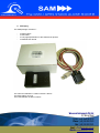
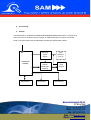
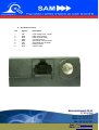
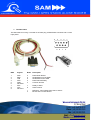
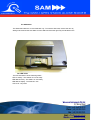
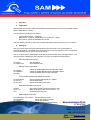
SAM The GSM / GPRS STAND ALONE MODEM 2W User Guide Wavecom Instruments Pty Ltd 257 Grange Road Findon, South Australia 5023 Phone: (+61) 08 8243 3500 Fax: (+61) 08 8243 3501 Email: [email protected] Website: www.wavecom.com.au ABN 60 065 609 225 WAVECOM Contents 1. 2. 3. 4. 5. 6. 7. 8. Overview Safety Precautions Radio frequency exposure - SAR WEEE directive 2002/96/EC Packaging Functionality a. b. c. d. e. General The RJ45 connector The Data cable The SIM holder The LED status a. b. Preparation Setting up Operation Electrical characteristics a. b. c. d. e. 9. Power supply RF band External antenna Temperature Conformity A typical application - Remote meter reading 10. Trouble shooting Appendix A : SAR calculations Appendix B : SAR statement for CE-application e Wavecom Instruments Pty Ltd t +61 3 9239 2000 257 Grange f +61 3 9561 2614Road Findon, South Australia 5023 .intercel.com.au Phone: (+61) 08 8243 3500 Toll free number for3501 Fax: (+61) 08 8243 Email: [email protected] Website: www.wavecom.com.au The Stand Alone modem, SAM, is designed to be a compact modem, easy to use for both mobile and fixed machine to machine applications. It has an RJ45 socket for serial data and input power, an FME male antenna connector, a SIM holder and an LED indicator. The SAM is a Quad-band 850/900/1800/1900MHz GSM/GPRS modem, capable of Circuit Switched Data, Packet Switched data, SMS and Fax. The RJ45 socket includes an RS232 serial port and input voltage signals. The LED is located next to the SIM holder, which allows users to monitor the status of the modem in operation. The SAM is controlled using a set of standard AT commands. 2. Safety Precautions The following safety precautions must be observed whenever the SAM modem is in operation or in service. Failure to comply with these precautions violates the safety standards of the design, manufacture and intended use of the product - Switch off the SAM modem : In hospitals or places where medical equipments may be in use In an aircraft Refueling points Explosive areas - Restricted use of the SAM modem Near any chemical plant Near any Fuel depot Areas with mobile phone warning sign Respect national regulations on the use of cellular devices. Road safety always comes first The SAM modem receives and transmit radio frequency energy while switched on, therefore interference can occur if the SAM is near TVs, radios, PCs or any inadequately shielded equipments. Wavecom Instruments Pty Ltd t +61 3 9239 2000 Grange Road f +61 257 3 9561 2614 Findon, South Australia 5023 e Phone:.intercel.com.au (+61) 08 8243 3500 Toll free number for Fax: (+61) 08 8243 3501 Email: [email protected] Website: www.wavecom.com.au 3. Radio frequency exposure - SAR The SAM2W modem is a low-power transceiver, similar to a typical handheld GSM/GPRS mobile phone. When it is turned on, it will emit low-level radio frequency energy. There are different guidelines and standards around the world that govern the permitted levels of radio frequency exposure for general population. The levels include a safety margin to a human body. The Specific Absorption rate (SAR) is a measure of the rate at which radio frequency energy is absorbed by the body when exposed to radio frequency electromagnetic field. The SAR value is determined at the highest certified power level in the laboratory conditions, but the actual SAR level of the transceiver while operating can be well below this value. This is because the transceiver is designed to use minimum power to connect to the network. The SAM2W modem is approved to use in applications where the antenna is placed more than 20cm from the body. Refer to the SAR calculations in the Appendix A. For other applications, the integrator is responsible for the local SAR requirements. 4. WEEE directive 2002/96/EC, disposal of old electronic equipment This symbol on the product indicates that this product shall not be treated as household waste . It must be placed at an appropriate collection point for the recycling of electrical and electronic equipments. By ensuring the correct disposal of this equipment, it will help the environm ent and human’s health. The recycling will help to conserve the natural resources. Wavecom Instruments Pty Ltd t +61 3 9239 2000 Grange Road f +61 257 3 9561 2614 Findon, South Australia 5023 e Phone:.intercel.com.au (+61) 08 8243 3500 Toll free number for Fax: (+61) 08 8243 3501 Email: [email protected] Website: www.wavecom.com.au 5. Packaging The SAM package consists of : - A SAM modem A data cable A one-page Specification of the SAM and its pinouts A SAM2W User Guide The carton box diameter is 120mm x 95mm x 60mm The Data cable is 2m long The Label diameter is 50mm x 33mm Wavecom Instruments Pty Ltd t +61 3 9239 2000 Grange Road f +61 257 3 9561 2614 Findon, South Australia 5023 e Phone:.intercel.com.au (+61) 08 8243 3500 Toll free number for Fax: (+61) 08 8243 3501 Email: [email protected] Website: www.wavecom.com.au 6. Functionality a. General The SAM modem is a Quad band 850/900/1800/1900MHz GSM/GPRS modem. It consists of an RJ45 connector for serial port and input power, an FME male antenna connector and a SIM holder. The LED located near the SIM holder indicates the SAM operating status. Switching Power Supply GSM/GPRS ENGINE SIM Interface RS232 Serial Data Interface Reset PADs 4-pin MicroFIT (optional) RJ45 Socket LED Indicator Wavecom Instruments Pty Ltd t +61 3 9239 2000 Grange Road f +61 257 3 9561 2614 Findon, South Australia 5023 e Phone:.intercel.com.au (+61) 08 8243 3500 Toll free number for Fax: (+61) 08 8243 3501 Email: [email protected] Website: www.wavecom.com.au b. The RJ45 connector Pin Signals Description 1 2 3 4 5 6 7 8 VIN DCD DTR GND RXD TXD RTS CTS Input voltage 5Vdc - 32Vdc Data Carrier Detect Data Terminal Ready Common Ground Serial Data out of the SAM Serial Data into the SAM Ready to Send Clear to Send Wavecom Instruments Pty Ltd t +61 3 9239 2000 Grange Road f +61 257 3 9561 2614 Findon, South Australia 5023 e Phone:.intercel.com.au (+61) 08 8243 3500 Toll free number for Fax: (+61) 08 8243 3501 Email: [email protected] Website: www.wavecom.com.au c. The Data cable The data cable is 2m long. It consists of an RJ45 plug, a DB9-female connector and a 2-wire input power. 5 4 9 3 8 DB9 Signals RJ45 Description 1 2 3 4 5 6 7 8 9 DCD RXD TXD DTR GND Not Used RTS CTS Not used 2 5 6 3 4 Data Carrier Detect Serial Data out of the SAM Serial Data into the SAM Data Terminal Ready Common Ground 7 8 Ready to Send Clear to Send 1 4 RED wire : Input voltage from 5Vdc to 32Vdc BLACK wire : Power Ground 2 7 1 6 Wavecom Instruments Pty Ltd t +61 3 9239 2000 Grange Road f +61 257 3 9561 2614 Findon, South Australia 5023 e Phone:.intercel.com.au (+61) 08 8243 3500 Toll free number for Fax: (+61) 08 8243 3501 Email: [email protected] Website: www.wavecom.com.au The SIM holder The SIM holder takes the 3V mini SIM card only. To insert the SIM card, remove the door by sliding it back toward the end. Make sure the SIM card faces the right way as indicated on the The LED status The LED indication has the following status : LED on steady : The SAM is on but not ready LED flashes slowly : The SAM is on and ready LED flashes rapidly : The SAM is in use LED is off : No power Wavecom Instruments Pty Ltd t +61 3 9239 2000 Grange Road f +61 257 3 9561 2614 Findon, South Australia 5023 e Phone:.intercel.com.au (+61) 08 8243 3500 Toll free number for Fax: (+61) 08 8243 3501 Email: [email protected] Website: www.wavecom.com.au 7. Operation a. Preparation Before power up the SAM, make sure the SIM card is inserted, the antenna is connected properly and the data cable is in place. The default factory setting for the SAM is : - Terminal Data speed : 115200bps Data format : 1 start bit, 8 data bits and one stop bit, no parity Flow control : RTS/CTS hardware flow control After the SAM is powered up, wait until the LED starts flashing before issuing any AT command. b. Setting up Use a PC with a terminal program (like Windows HyperTerminal) to set up the SAM for a particular application. The following AT commands can be used as a guide. For the complete set of AT commands, refer to the AT command manual. The AT command to the SAM always starts with AT and ends with <CR> (Carriage Return). The response from the SAM starts and ends with <LF><CR> (LineFeed+Carriage Return) - SIM card related commands : AT+CPIN? AT+CPIN=xxxx - Network related commands : AT+CREG? AT+CGREG? AT+CSQ - Set the terminal data speed (ex. =9600) Set the data format Set the local flow control option GSM data call related commands : ATS0=2 ATDn...nn ATA - Check the SAM’s GSM network registration status Check the SAM’s GPRS network registration status Check the SAM’s received signal strength Terminal data speed/format related commands : AT+IPR=speed AT+ICF=x,y AT+IFC=a,b - Ask SIM status Enter SIM PIN xxxx Set to auto-answer incoming call after 2 rings Make an outgoing data call to number n...nn Answer the incoming call GPRS related commands AT+CGDCONT=1,”IP”,”APN” AT+CGQREQ AT+CGATT AT+CGACT Set the GPRS context 1 Set up the quality of service GPRS attach/detach GPRS context activate/deactivate Wavecom Instruments Pty Ltd t +61 3 9239 2000 Grange Road f +61 257 3 9561 2614 Findon, South Australia 5023 e Phone:.intercel.com.au (+61) 08 8243 3500 Toll free number for Fax: (+61) 08 8243 3501 Email: [email protected] Website: www.wavecom.com.au c. How to : - Send an SMS in text mode : AT+CMGF=1 Set TEXT mode AT+CSCA? Check Service centre address AT+CMGS= Destination phone number Enter text here, ends with <Control-Z> to send +CMGS: 44 Text message is sent OK - Receive an SMS in Text mode +CMTI: “SM”,4 AT+CMGR=4 - Make an outgoing data call ATDn...nn<cr> CONNECT 115200 Data transfer back and forth +++ ATH - Make a data call to a data number Connected Back to command mode Hang up data call Receive a data call RING ATA CONNECT 115200 NO CARRIER - Message received, stored in location 4 Command to read it Incoming call received Take it Call connected Call terminated Connect to GPRS (packet data) network Use HyperTerminal to set this AT command : AT+CGDCONT=1,”IP”,”APN” Set Access Point Node ( Example AT+CG DCONT=1,”IP”,”telstra.internet”) Exit HyperTerminal For Windows XP : Select Control Panel -> Select Phone/Modem options -> Add Standard 19200bps modem -> Set modem maximum port speed to 115200, select COM port. In Windows Dial-up networking, create a new connection -> Select connect using the Standard 19200bps modem -> Configured to 115200, hardware flow control Select phone number : *99**1# Click Dial. Wavecom Instruments Pty Ltd t +61 3 9239 2000 Grange Road f +61 257 3 9561 2614 Findon, South Australia 5023 e Phone:.intercel.com.au (+61) 08 8243 3500 Toll free number for Fax: (+61) 08 8243 3501 Email: [email protected] Website: www.wavecom.com.au 11 8. a. Power supply : GSM850/900 GSM1800/1800 Maximum Input current @ 5V Power=33.10dBm GSM850/900 During 2Tx bursts @ Pcl5 @ 13.2V Power=33.0dBm DCS1800/1900 During 2Tx bursts @ Pcl0 @ 32V 2.1A 1.88A 1.4A 1.1A 610mA 390mA Average Input current @ 5V Power=33.10dBm GSM850/900 Average 3Rx/2Tx @ Pcl5 @ 13.2V Power=33.0dBm DCS1800/1900 Average 3Rx/2Tx @ Pcl0 @ 32V 500mA 390mA 400mA 160mA 95mA 80mA Average input current in idle mode, where RF active Modem synchronized with Network but there is no communication @ 5V 34mA 34mA @ 13.2V 18mA 18mA @ 32V 9mA 9mA b. RF band EGSM900 DCS1800 GSM850 PCS1900 Tx Frequency Rx Frequency 880-915MHz 925-960MHz 1710-1785MHz 824-849MHz 1805-1880MHz 869-894MHz 1850-1910MHz 1930-1990MHz Rx sensitivity Linear dynamic range Co-channel rejection -104dBm 63dB ≥9dBc -102dBm 63dB ≥9dBc -104dBm 63dB ≥9dBc -102dBm 63dB ≥9dBc Max Output Power Min Output Power 33dBm±2dB 5dBm±5dB 30dBm±2dB 0dBm±5dB 33dBm±2dB 5dBm±5dB 30dBm±2dB 0dBm±5dB Wavecom Instruments Pty Ltd t +61 3 9239 2000 Grange Road f +61 257 3 9561 2614 Findon, South Australia 5023 e Phone:.intercel.com.au (+61) 08 8243 3500 Toll free number for Fax: (+61) 08 8243 3501 Email: [email protected] Website: www.wavecom.com.au The recommended dual-band or quad-band antenna used with the SAM should have the c. following characteristics : - Frequency range : Quad band GSM 850/900/1800/1900MHz Impedance : 50Ω VSWR : Rx Max = 1.5 : 1, Tz Max = 1.5 : 1 Typical radiated Gain : 0dBi d. Temperature : - Operating temperature : -20ºC to +55ºC Storage temperature : -25ºC to 70ºC e. Conformity : - Safety standard : EN60950 Efficient use of radio spectrum : EN301 419 (Ver 4.1.1) EN301 511 (Ver 7.0.1) EMC : EN 301 489-1, EN301 489-7 Global Certification Forum- Certification Criteria : GCF-CC 3.13 Wavecom Instruments Pty Ltd t +61 3 9239 2000 Grange Road f +61 257 3 9561 2614 Findon, South Australia 5023 e Phone:.intercel.com.au (+61) 08 8243 3500 Toll free number for Fax: (+61) 08 8243 3501 Email: [email protected] Website: www.wavecom.com.au 9. In this application, the SAM2W modem is connected to an electricity meter, which is located at a remote site, and the area is covered by the GSM/GPRS network. At the office, the Operator is equipped with a computer, connected to a landline (PSTN) modem, or another SAM2W modem. To read the remote meter, the Operator uses the computer and the connected modem, and calls the SAM2W at the remote site. The SAM2W modem will answer and provide a transparent data path from the remote meter to the computer at the office. After all data is read from the remote meter, the operator will instruct the computer to hang up the call, which causes the remote SAM2W modem to terminate the call. External antenna GSM/GPRS Network SAM2w MODEM OR PSTN MODEM PSTN Network Configuration at the office External antenna GSM/GPRS Network At the remote site Wavecom Instruments Pty Ltd t +61 3 9239 2000 Grange Road f +61 257 3 9561 2614 Findon, South Australia 5023 e Phone:.intercel.com.au (+61) 08 8243 3500 Toll free number for Fax: (+61) 08 8243 3501 Email: [email protected] Website: www.wavecom.com.au a. The modem does not respond to AT command - Check power supply : The input voltage must be from 5Vdc to 30Vdc. The supply current must be capable of 1.7A @ 5Vdc Check the serial data cable : Make sure the serial data cable is configured correctly according to the diagram on section 6.c above Check that the terminal program on your PC is configured correctly : communication port, data speed, data format, flow control. Check that there is no conflict on the selected serial communication port. b. The modem always returns “ERROR” to AT commands Issue AT+CMEE=1 to modem and check the returned error code. The following table indicates some common errors : Error code Error meaning Hint 0 3 4 10 11 12 13 16 17 18 26 30 Modem failure Call technical support Operation not allowed Operation not supported SIM not inserted Check SIM card, clean contacts SIM PIN required Enter SIM PIN SIM PUK required Call the network operator SIM failure Check the SIM validity Incorrect password SIM PIN2 required SIM PUK2 required Dialed number exceeds 20 digits No network service See other error codes in the AT command manual c. The modems always returns “NO CARRIER” when making an outgoing call. After the modems returns “NO CARRIER”, issue AT+CEER to check the error code. Error code Error meaning Hint 1 16 17 18 19 21 22 31 50 68 252 253 Unallocated phone number Normal call clearing Called party busy No response from the called party Called party alerting, no answer Call rejected Number changed Normal, unspecified Requested facility not subscribed ACM ≥ Max ACM Call barring on outgoing calls Call barring on incoming calls See other error codes in the AT command manual. Check with the network No credit on prepaid SIM Wavecom Instruments Pty Ltd t +61 3 9239 2000 Grange Road f +61 257 3 9561 2614 Findon, South Australia 5023 e Phone:.intercel.com.au (+61) 08 8243 3500 Toll free number for Fax: (+61) 08 8243 3501 Email: [email protected] Website: www.wavecom.com.au d. - Check the antenna : proper connection, correct 50 Ω type, correct frequency range 850/900/1800/1900MHz. - Check Rx signal strength : Use AT+CSQ to check the Rx signal strength. General rule of thumb, signal greater than 12 is sufficient. e. Care and maintenance The GSM modem is an advanced piece of engineering equipment and should be treated with care. The suggestion below will help to prolong the modem’s life: - Do not expose the modem to extreme temperature and/or high humidity. - Do not attempt to disassemble the modem. There is no serviceable part inside. - The modem is not water-proof - Handling the modem with care - Do not operate the modem next to any magnetic media such as computer disks, credit cards… The magnetic information may be affected by the RF. - The modem is not a toy, please keep out of reach of children. Use authorized service centres only. Wavecom Instruments Pty Ltd t +61 3 9239 2000 Grange Road f +61 257 3 9561 2614 Findon, South Australia 5023 e Phone:.intercel.com.au (+61) 08 8243 3500 Toll free number for Fax: (+61) 08 8243 3501 Email: [email protected] Website: www.wavecom.com.au a. Norminal antenna gain EGSM-900 Tx Frequency in MHz Max power density S=f/200 (W/m²) DCS-1800 Min Max Min Max 880 915 1710 1785 4.575 8.550 8.925 4.400 Power to the antenna (W) 2 2 1 1 Norminal antenna gain dB 0 0 0 0 Norminal antenna gain G 1 1 1 1 Distance from the antenna to POI : R=[(PG/4πS)]½ 19.02cm 18.65cm 9.65cm 9.44cm APPENDIX A : SAR CALCULATIONS FOR THE SAM2W b. Maximum antenna gain EGSM-900 Tx Frequency in MHz Max power density S=f/200 (W/m²) DCS-1800 Min Max Min Max 880 915 1710 1785 4.575 8.550 8.925 4.400 Power to the antenna (W) 2 2 1 1 Norminal antenna gain dB 0.5 0.5 0.5 0.5 Norminal antenna gain G 1.122 Distance from the antenna to POI : R=[(PG/4πS)]½ 20.15cm 1.122 19.76cm 1.122 10.22cm 1.122 10.00cm Wavecom Instruments Pty Ltd t +61 3 9239 2000 Grange Road f +61 257 3 9561 2614 Findon, South Australia 5023 e Phone:.intercel.com.au (+61) 08 8243 3500 Toll free number for Fax: (+61) 08 8243 3501 Email: [email protected] Website: www.wavecom.com.au Appendix B SAR STATEMENT FOR THE SAM2W CE-CERTIFICATION APLLICATION To whom it may concern The SAM2W is a GSM/GPRS modem, that sends/receives data over the GSM/GPRS network. This modem is designed for Machine-to-Machine applications. This modem does not have an integral antenna. Depending on customers’ requests, the SAM2W modem may/may not be supplied with an antenna. In the cases of customers wanting to acquire the antennas themselves, the antenna specification is included in the User Guide. A typical application will require the SAM2W to be connected to an external dual-band 900/1800MHz antenna , as described in the User Guide. Based on the standards EN50385 and EN50383, a minimum safety operating distance has been calculated and stated in the User Guide Safety distance requirement : The SAM2W modem should NOT be operated when a person is within 203mm (8 inches) of the modem. On behalf of Wavecom Sang Vu Technical Director Wavecom Instruments Pty Ltd t +61 3 9239 2000 Grange Road f +61 257 3 9561 2614 Findon, South Australia 5023 e Phone:.intercel.com.au (+61) 08 8243 3500 Toll free number for Fax: (+61) 08 8243 3501 Email: [email protected] Website: www.wavecom.com.au