1
uni
en@
PRO 810e
Professional CB Base Station
OWNER'S MANUAL
--
----..--
.--....
l
Welcome!
To the world of sophisticated, microprocessor controlled CB radio communications. Your Uniden PRO 81 Oe represents the most advanced base station ever
designed for use in the Citizens Band Radio SeNice. It will operate on anyofthe 40
AM, 40 usa, and 40 LSBfrequencies authorized by the Department of Communications. Your PRO 81Oe features a superheterodyne circuit with PHASELOCKED
LOOP techniques to assure precise frequency control. This radio has been type accepted and certified by the D.O.C
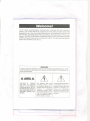
WARNING
UNIDEN DOES NOT REPRESENT THE UNIT TO HAVE BEEN WA TERPROOFED.
TO REDUCE THE RISK OF FIRE OR ELECTRIC SHOCK, DO NOT EXPOSE THIS APPLIANCE TO
RAIN OR MOISTURE.
A
Lt
A
CAUTION: TO
REDUCE
THE RISK OF ELECTRIC
SHOCK, DO NOT REMOVE
COVER (OR BACK). NO USER-SERVICEABLEPARTSINSIDE. REFERSERVICINGTO
QUALIFIED SERVICE PERSONNEl.
The lightning flash with
arrowhead symbol, within
an equilateral triangle, is intended to alert the userto the
presence of uninsulated
"dangerous voltage" within
the product's enclosure that
may be of sufficient magnitude to constitute a risk of
electric shock to persons.
Lt
The exclamation point within
an equilateral triangle is intended to alert the userto the
presence of important operating and maintenance
(servicing) instructions in the
literature accompanying the
appliance.
-1
-
.
--------.--_....----
"
,
I
,--_...
I~
-.
.",
Installation
Select a location that is convenient for operation and allows adequate air circulation around the unit. Do not place anything directly on top of the radio cabinet
which would block the cooling vents. Avoid areas of high heat. Do not place the
unit on top of radiator vents or in direct sunlight. Do not place the unit in high
moisture environments such as bathrooms.
Antenna
Since the maximum allowable power output of the transceiver is limited by the
D.O.C, the antenna isa very important factor affecting transmission distance. It is
for this reason that we strongly recommend that you install only a quality antenna
in your new CB radio system. You have purchased a superior quality transceiver.
Don't diminish its performance by installing an inferior antenna.
Only a properly matched antenna system will allow maximum power transfer from
the 50-ohm transmission line to the radiating element. We recommend that you
use an SWRmeter when installing your antenna. Set your PRO81 Oeto channel 20
and make adjustments to the antenna until the meter shows SWR = 1. Your
Uniden dealer is qualified to assist you in the selection of the proper antenna to
meet your application requirements.
The PRO 81 Oe may be used with any type of 50 ohm base station antenna. A
ground plane vertical antenna will provide the most uniform horizontal coverage.
This type of antenna is best suited for communication with a mobile unit. For
point to point operation where both stations are fixed, a directional beam will
usually increase communication range since this type of antenna concentrates
transmitted energy in one direction. The beam antenna also allows the receiver to
"listen" in only one direction thus reducing interfering signals.
Antenna height is an important factor when maximum range is desired. Keep the
antenna clear of surrounding structures and foliage. D.O.C regulations may limit
antenna height above an existing structure.
Connect the male connector (PL-259)of the coaxial cable from the antenna to the
female connector on the back of the unit.
- _. -
--
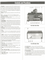
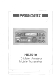
1. Microphone - The operational mode of the CB is controlled by the push-totalk switch on the mic. Pressthe switch to activate the transmitter and disable the
receiver. Release the switch to enable the receiver and disable the transmitter.
When transmitting, hold the micabout 2 inches fromyour mouth and speak clearly in a normal voice. The mic included with the PRO 81Oe is a detachable, Iow
impedance, dynamic type.
2. Mic Gain - Adjust the microphone sensitivity for crisp, clear audio transmission.
3. CH 9 -- A single key gives instant access to the emergency channel 9.
4. Illuminated S/RF Meter - An accurate analog meter displays the signal
strength of both the transmitter and receiver.
5. TX & RXLEDs- The TXLEDlights when transmitting and the RXLEDlights
when receiving.
6. Channel Display - A large LEDdisplay shows the channel currently in use.
7. Channel Selector - An oversize channel knob makes it easy to select any of
the forty channels. This switch selects the desired channel for transmission and
reception. All channels, except channel 9, may be used for communications between stations operating under different license. Channel 9 has been reseNed by
the D.O.C for emergency communications.
8. Clarifier - Used for fine tuning when operating in USBor LSBmodes.
9. Hi Cut Switch - The Hi Cut switch is used to remove high frequency hiss and
other formsof noise from the receivedsignal. Pressthe HiCut switch to activate
this feature.
10. RF Gain - This control is used to adjust signal reception in areas where
strong signals are present. Turn the control fully clockwise for maximum reception.
11. Squelch - The Squelch control is used to eliminate background noise during
the absence of a transmission. Turn the control fully counter clockwise, then
slowly rotate it back, clockwise until all noise disappears. At this setting any transmission must be slightly stronger than the background noise to "Break Squelch" or
to be heard. Further clockwise rotation will increase the threshold at which a signal will be heard. You can select any level to "Break Squelch"
12. Volume with Power On/Off Control - Turn the unit on and adjust the
volume.
13. NB/ ANL Key - Select the Noise Blanker and Automatic Noise Limiter to
help reduce electrical noise or other interference.
14. AM/USB/LSB Switch - Selects either Amplitude Modulation, Upper
Sideband, or Lower Sideband for transmission and reception.
15. PA Key - Select the Public Address mode if an external PA speaker is connected.
16. Power 7 Watt Audio Output - Enhanced audio circuitry with Tone adjustment and a booming 7 watt audio output provide CB reception like you've
never heard it before.
17. Rugged Metal Cabinet - A professional quality metal housing insures
years of dependable use.
9
13
16
2
1
5
4
6
3
15 12 11 10 14
Pro 810e Front View
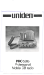
17
20
19
21
Pro 810e Rear View
11
~I
18. AC Power Cord - Connect to any 240 V house hold AC outlet.
19. PA Speaker - An external 8 ohm 7-watt speaker must be connected to the
"PASP"jack located on the back of the unit. The speaker must be directed away
from the mic to prevent feedback.
20. External Speaker - The "EXT.SP."jack is used for remote receiver monitoring. The external speaker should have an 8 ohm impedance and be rated at least 7
watts. When an external speaker is connected, the internal speaker is disabled.
21. Antenna Connector - This female connector permits connection of the
transmission line cable male connector (PL-259)to the transceiver.
r
_.
....
0
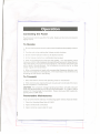
eration
Connecting the Power
Plug the power cord into any 240 VAC outlet. Make sure the cord is not kinked or
tightly wound.
To Receive
1. Besure that the power source, antenna and microphone are properly connected.
2. Turn the unit on by rotating the Volume control clockwise.
3. Set the channel selector switch to the desired channel.
4. Set the Volume control to a comfortable listening level.
5. Listen to the background noise from the speaker. Turn the Squelch control
clockwise until the noise disappears (no signal should be present). Leave the control at this setting. The squelch is now properly set. The receiver will remain quiet
until a signal is actually received. Do not advance the control too far, or some
weaker signals will not be heard.
6. When a transmission is heard with annoying high frequency distortion, activate the Hi Cut feature to eliminate this. If the transmission has interference try
activating the ANL and/or the NB key.
To Transmit
1. Select the desired channel and operating mode for transmission.
2. Ifthe channel is clear, depress the push-ta-talk switch on the side of the microphone and speak in a normal voice.
CAUTION: The transceiver Voltage Standing Wave Ratio (V.S.W.R.)measurement must be performed prior to the use of the transmitter. A "V.S.W.R."ratio in
excess of 2: 1 may damage the transmitter. Please check your SWR reading frequently with an SWRmeter.
Preventative
Maintenance
At six to twelve month intervals, the following system checks should be made:
1. Check the Standing Wave Ratio (V.S.W.R.)
2. Inspect all electrical connections
3. Inspect antenna coaxial cable for wear
-- - .- -
--'.-.
l
-"-
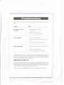
Troubleshootin
If your
PRO81 Deis not performing up to your expectations, please try these simple
steps:
Trouble
Check
Unit will not turn on.
No power.
1. Check power cord and all
connections.
2. Check wall switch if any.
3. Check house electrical system.
Poor reception
1. Check and adjust Squelch.
2. Check antenna system and cable, connectors.
3. Check operation mode of the radio.
Weak transmission
1. Check antenna system and cable, connectors.
2. Check antenna grounding.
3. Check for corrosion on connectors.
Ifyou determine that se Nice is necessary contact your local dealer or pack the unit
in its original carton. Send it along with a brief, concise description of the problem, your name, address, phone number, and a copy of the original purchase
receipt to the address listed in the warranty.
SERVICING YOUR CB
Technical information, diagrams and charts will be provided upon request. We
highly recommend that you consult a qualified radiotelephone technician for service and alignment of this radio. When ordering parts, it is important to specify the
correct model number and serial number of this radio.
Please refer to the WARNING information on the first page of this manual.
,,'," .,c,,'.'
'=r
--- - --- -
-==::
-~
<::.
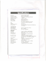
S ecifications
Channels:
Frequency Range:
Frequency Control:
Frequency Tolerance:
Operating Temp.:
Microphone:
Input Voltage:
Current Drain:
Size:
Weight:
Antenna Connector:
Analog Meter:
TRANSMITTER
Power Output:
Freq. Response:
Output Impedance:
RECEIVER
Sensitivity:
Selectivity:
Image Rejection:
I.F. Frequency:
RF Gain Control:
Automatic Gain:
Noise Blanker:
Squelch:
Audio Output Power:
Freq. Response:
Distortion:
Internal Speaker:
External Speaker:
PA System:
. --- - ---
40 AM, 40 usa, 40 LSB
26.965 to 27.405 MHz
Phase Locked Loop (PLL)synthesizer
::!:0.005%
- 30°C to + 50°C
Plug in type: dynamic
240V AC 50 Hz
TX:full mod., 400 mA
RX:with max audio output, 200 mA
14 3/8" W x 8 7/8" D x 3 3/4"H
3 lb. 2 oz.
UHF, SO-239
Indicates relative RFoutput and received signal strength
Maximum Legal Output Power
450
-
2500 Hz
50 ohms, unbalanced
0.5#V for 10dB; (S + N)/N typical
6dB @4.2KHz, 60dB @7KHztypical
80 dB typical
Single Conversion Superheterodyne
10.695 MHz
Adjustable for optimum reception
(AGC):lessthan 10dB change in audio output
for inputs from 10 to 50.000 microvolts
RFtype
Adjustable; threshold less than 1#V
7 watts max. into 8 ohms
250 to 2500 Hz
less than 10% at 3 watts, @ 1000Hz
16 ohms, 7 watts oval
(not supplied) 8 ohms
7 watts in external 8 ohm speaker
i-
-
l
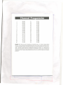
Channel Fre uencies
1
2
3
4
5
6
7
8
9
10
11
12
13
14
15
16
17
18
19
20
26.965
26.975
26.985
27.005
27.015
27.025
27.035
27.055
27.065
27.075
27.085
27.105
27.115
27. 125
27.135
27.155
27.165
27.175
27.185
27.205
21
22
23
24
25
26
27
28
29
30
31
32
33
34
35
36
37
38
39
40
27.215
27.225
27.255
27.235
27.245
27.265
27.275
27.285
27.295
27.305
27.315
27.325
27.335
27.345
27.355
27.365
27.375
27.385
27.395
27.405
NOTE: This radio has been designed to operate in the 11 meter Citizens Radio
SeNice. Ituses a frequency synthesizing circuit with Phase Locked Loop (PLLJtechniques to provide crystal controlled transmit and receive operation on all 40 channels. The PLLcircuitry assures ultraprecise frequency control. It is designed to
meet the Department of Communications requirements applicable to equipment
operating in the Citizens Band Radio SeNice, and is not to be used for any other
purpose.
....
-
l
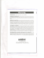
Warran
I
WARRANTOR: Uniden Australia Pty. Ltd. ("UN/DEN").
ELEMENTSOF WARRANTY: Uniden warrants, for the duration of this warranty, UN/DEN CBProduct (hereinafter referred to as the Product) to be free from defects in materials and craftsmanship with only the limitations or exclusions set out
below.
WARRANTY DURATION: Thiswarranty shall terminate and be of no further effect one (I) year after the date of the original purchase of the Product or at the time
the Product is (A)damaged or not maintained as reasonable and necessary, (B)
modified, (C) improperly installed, (D)repaired by someone other than warrantor
for a defect or malfunction covered by this warranty, (E)used in a manner or purpose for which the Product was not intended, or (F)sold by the original purchaser.
STATEMENTOF REMEDY:In the event that the Product does not conform to
this warranty at any time while this warranty is in effect, warrantor will repair the
defect and return it to you without charge for parts, seNice, or any other cost incurred by warrantor or its representatives in connection with the performance of
this warranty. THISWARRANTYDOES NOT COVER OR PROVIDE FOR THE
REIMBURSEMENTOF PAYMENTOF INCIDENTALOR CONSEQUENTIALDAMAGES.Some states do not allow this exclusion or limitation of incidental or consequential damages, so the above limitation or exclusion may ~ot apply to you.
PROCEDURE FOR OSTAINING PERFORMANCE OF WARRANTY: In the
event that the Product does not conform to this warranty, the Product should be
shipped or delivered, freight prepaid, to warrantor at Uniden Australia Pty. Ltd.
345 Princes Highway, Rockda/e, N.S.W.2216 with evidence of original purchase.
uniden@
CUSTOMERSERVICE
345 Princes Hwy, Rockda/e, NSW. 2216
Phone (02) 599 3100 Fax (02) 599 3278
..,
~
---~---
-
.---
I
~
I
1 '-'-'"
~
.~
~~~-
-====
0_-
-.
r-1--.
uniden@
AUSTRALIA PTY. LTD.
345 PrincesHighway, Rockdale,N.S.W. 22 J6
Phone: (02) 599 3355
Fax:(02) 599 40 J8
UTUAO I 552CA
Printed in the Philippines
-,
-
..-no.
,-'
."
I
"'---
--n.-- -"