1
Datacom Systems Inc
Access Your Network
TM
SS-1200-S Series Link Aggregation Taps
SS-2200-S Series Dual-Link Aggregation Taps
SS-4200-S Series Quad-Link Aggregation Taps
SS-1200-S, SS-2200-S, SS-4200-S Series
Link Aggregation Taps
USER guide
June 2012
541-0132-U-B.02
© 2012 Datacom Systems Inc
Product Description
Datacom Systems Inc. SINGLEstream™ SS-1200-S Series Link Aggregating
Taps, the SS-2200-S Series Dual-Link Aggregating Taps and the SS-4200-S
Series Quad-Link Aggregating Taps are made to be adaptable. The hard-wired
TAP ports serve only as In-Line taps and the remaining Any-to-Any ports can
be configured by the Command Line Interface (CLI) to be either input or output
ports. The SINGLEstream™ Link, Dual-Link and Quad-Link Aggregating Taps
combine or aggregate data streams, allowing any connected network device/tool
to receive a full stream of data with one NIC.
The Datacom System SINGLEstream™ SS-1200-S Series Link Aggregating
Taps, the SS-2200-S Series Dual-Link Aggregating Taps and the SS-4200-S
Series Quad-Link Aggregating Taps support your ability to specifically apply
your peripheral network tools to the analysis requirements and adapt with your
ever-changing network.
SS-1200-S, SS-2200-S and SS-4200-S Series Link Aggregating Taps
© 2012 Datacom Systems Inc
All rights reserved. No parts of this work may be reproduced in any form or by any means - graphic, electronic, or
mechanical, including photocopying, recording, taping, or information storage and retrieval systems - without the
written permission of the publisher.
Products that are referred to in this document may be either trademarks and/or registered trademarks of the
respective owners. The publisher and the author make no claim to these trademarks.
While every precaution has been taken in the preparation of this document, the publisher and the author assume no
responsibility for errors or omissions, or for damages resulting from the use of information contained in this
document or from the use of programs and source code that may accompany it. In no event shall the publisher and
the author be liable for any loss of profit or any other commercial damage caused or alleged to have been caused
directly or indirectly by this document.
Printed: June 2012 in East Syracuse, New York
Contents
5
Table of Contents
Section 1 Terms of Use
9
1 Copyright
................................................................................................................................... 9
2 License...................................................................................................................................
Agreement
9
3 Trademark
...................................................................................................................................
Attribution
9
4 Proprietary
...................................................................................................................................
Notice
9
5 Certifications
...................................................................................................................................
and Marks
10
6 Safety...................................................................................................................................
Notices and Warnings
10
Section 2 Overview
11
1 LINKprotect™
................................................................................................................................... 11
2 SINGLEstream™
...................................................................................................................................
Series Summary
11
3 What ...................................................................................................................................
Shipped?
12
4 SINGLEstream™
...................................................................................................................................
Series Features and Benefits
12
5 SINGLEstream™
...................................................................................................................................
Series Common Specifications
13
6 SS-1200
...................................................................................................................................
Series Model Specific Specifications
14
7 SS-2200
...................................................................................................................................
Series Model Specific Specifications
14
8 SS-4200
...................................................................................................................................
Series Model Specific Specifications
15
Section 3 Hardware
17
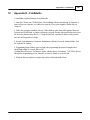
1 SS-1200
...................................................................................................................................
Series Front Panels
17
2 SS-2200
...................................................................................................................................
Series Front Panels
18
3 SS-4200
...................................................................................................................................
Series Front Panels
18
4 Front ...................................................................................................................................
Panel Description
19
Pow er
.......................................................................................................................................................... 19
TAP Ports
.......................................................................................................................................................... 19
Any-to-Any Ports
.......................................................................................................................................................... 20
Managem ent ..........................................................................................................................................................
Port
21
5 Rear Panel
...................................................................................................................................
Description
21
Serial DB9
.......................................................................................................................................................... 22
Pow er Sw itch..........................................................................................................................................................
(SFP series)
22
Rear Label (BT..........................................................................................................................................................
series)
22
Rear Labeling..........................................................................................................................................................
(SFP series)
22
Input Pow er .......................................................................................................................................................... 22
Section 4 Initial Configuration
23
1 Command
...................................................................................................................................
Line Interface (CLI)
23
Basic Functionality
.......................................................................................................................................................... 23
Passw ord Recovery
.......................................................................................................................................................... 24
Basic Com m ands
..........................................................................................................................................................
(Read Only Access)
24
EXIT (EX) ......................................................................................................................................................... 24
HELP (HE) .........................................................................................................................................................
or (?)
24
POWER STATUS
.........................................................................................................................................................
(PO ST)
25
SHOW (SH)
......................................................................................................................................................... 26
© 2012 Datacom Systems Inc
6
SS-1200-S, SS-2200-S and SS-4200-S Series Link Aggregating Taps
.........................................................................................................................................................
27
SHOW GROUPS
(SH GR)
SHOW MANAGEMENT
.........................................................................................................................................................
(SH MA)
27
SHOW PORT
.........................................................................................................................................................
CONFIG (SH PO CO)
28
SHOW PORT
.........................................................................................................................................................
ROUTING (SH PO RO)
30
SHOW PRODUCT
.........................................................................................................................................................
(SH PR)
30
SHOW TIME
.........................................................................................................................................................
(SH TI)
30
SHOW USERS
.........................................................................................................................................................
(SH US)
31
Superuser Com
..........................................................................................................................................................
m ands (Configuration Access)
31
SU (SU) ......................................................................................................................................................... 31
SU SET PASSWORD
.........................................................................................................................................................
(SU SE PA)
31
SET PROMPT
.........................................................................................................................................................
(SE PR)
31
ADD USER.........................................................................................................................................................
(AD US)
32
EDIT USER.........................................................................................................................................................
(ED US)
32
DELETE USER
.........................................................................................................................................................
(DE US)
32
SET DATE .........................................................................................................................................................
(SE DA)
32
SET TIME (SE
.........................................................................................................................................................
TI)
33
SET IP (SE.........................................................................................................................................................
IP), SUBNET (SU), GATEWAY (GA)
33
SET SUBNET
.........................................................................................................................................................
(SE SU)
33
SET GATEWAY
.........................................................................................................................................................
(SE GA)
34
SET PORT .........................................................................................................................................................
GROUP (SE PO GR)
34
SET PORT .........................................................................................................................................................
MONITOR (SE PO MO)
34
SET PORT .........................................................................................................................................................
NAME (SE PO NA)
35
SET PORT .........................................................................................................................................................
SPEED (SE PO SP)
35
SET PORT .........................................................................................................................................................
VTAG (SE PO VT)
35
SET LINK PROTECT
.........................................................................................................................................................
(SE LP)
36
SET TCP PORT
.........................................................................................................................................................
(SE TC PO)
37
SET UPGRADE
.........................................................................................................................................................
(SE UP)
37
SET TELNET
.........................................................................................................................................................
(SE TT)
37
SET SSH (SE
.........................................................................................................................................................
SH)
38
SET SSH KEY
.........................................................................................................................................................
(SE SH KY)
38
SET PING (SE
.........................................................................................................................................................
PI)
38
SET SNMPv3
.........................................................................................................................................................
(SE V3)
39
SET SNMPv3
.........................................................................................................................................................
SUPERUSER (SE V3 SU)
39
2 SERIAL
...................................................................................................................................
Port Configuration (DB9)
40
HyperTerm inal
.......................................................................................................................................................... 40
3 MANAGEMENT
...................................................................................................................................
Port Configuration (RJ45)
40
HyperTerm inal
.......................................................................................................................................................... 41
TELNET
.......................................................................................................................................................... 41
4 IP Address
...................................................................................................................................
Configuration
42
IP Address Configuration
..........................................................................................................................................................
w ith HyperTerm inal
42
IP Address Configuration
..........................................................................................................................................................
w ith TELNET
46
5 Exercise
...................................................................................................................................
- CLI Setting Ports
50
6 Management
...................................................................................................................................
Connection (RJ45)
53
TELNET
SSH
.......................................................................................................................................................... 54
.......................................................................................................................................................... 55
7 SNMP...................................................................................................................................
Configuration
57
8 Small...................................................................................................................................
Form-Factor Plug Module
58
Intallation Prerequisites
.......................................................................................................................................................... 58
Safety Guidelines
.......................................................................................................................................................... 58
Installing the SFP
..........................................................................................................................................................
Module
59
Rem oving the..........................................................................................................................................................
SFP Module
59
© 2012 Datacom Systems Inc
Contents
Section 5 Hardware Installation
7
61
1 TAP Connection
................................................................................................................................... 61
Copper SS-1200BT-S
..........................................................................................................................................................
and SS-2200BT-S series
61
Fiber Optic SS-1200LX-S
..........................................................................................................................................................
and SS-1200SX-S series
62
2 Power................................................................................................................................... 63
3 Any-to-Any
...................................................................................................................................
Connection
63
4 Management
...................................................................................................................................
Connection
64
Section 6 Functional Drawing
65
1 SS-1200-S
...................................................................................................................................
Series
65
2 SS-2200-S
...................................................................................................................................
Series
67
3 SS-4200-S
...................................................................................................................................
Series
68
Section 7 Application
69
1 SS-1200
...................................................................................................................................
Series
69
Utilization less..........................................................................................................................................................
than 50 percent (HyperTerm inal configuration exam ple)
69
Utilization greater
..........................................................................................................................................................
than 50 percent (Telnet configuration exam ple)
72
2 SS-2200
...................................................................................................................................
Series
75
Tapping the Firew
..........................................................................................................................................................
all (Telnet configuration exam ple)
75
Section 8 Customer Service
79
1 Internet
................................................................................................................................... 79
2 Warranty
................................................................................................................................... 79
3 Limits...................................................................................................................................
of Liability
79
Section 9 Appendix A - Agent Capabilities MIB
Section 10 Appendix B - Power Supply MIB
Section 11 Appendix C - Structure of Management
Information MIB
Section 12 Appendix D - FLASHutils
81
89
103
109
© 2012 Datacom Systems Inc
Terms of Use
1
9
Terms of Use
The following terms and conditions relate to the use of this document. Please note that Datacom
Systems Inc. reserves the right, at its entire discretion, to change, modify, add, or remove portions of
these Terms of Use at any time. Please read the Terms of Use carefully as your use of this document
is subject to the Terms of Use stipulated herein.
1.1
Copyright
Copyright© 2011 by Datacom Systems, Inc. All rights reserved. Printed in the United States of
America. No part of this publication may be reproduced, stored in a retrieval system, or transmitted,
in any form or by any means, electronic, mechanical, photocopying, recording, or otherwise, without
the prior written permission of Datacom Systems, Inc. To obtain this permission, write to the
attention of the Datacom Systems legal department at 9 Adler Drive, East Syracuse, New York
13057-1290, or call +1 315-463-9541.
1.2
License Agreement
Notice To All Users: By using Datacom Systems, Inc. products, you agree to the terms set forth.
No licenses, express or implied, are granted with respect to the technology described and Datacom
Systems, Inc. retains all rights with respect to the technology described herein. If applicable, you
may return the product to the place of purchase for a full refund.
1.3
Trademark Attribution
Access Your Network , DS3 ACTIVEtap , DS3switch , ETHERNETtap , Empowering
Network Professionals , FDDIswitch , FIBERsplitter , FIBERswitch , FIBERSWITCHsystem , FLOWcontrol , GIGABITswitch , INSERTswitch , INSERTunit , LANswitch ,
LINKprotect , MANAgents , MULTINETswitch , NETspan , PERMAlink , PROline ,
RMON SWITCHINGanalyzer , SINGLEstream , UNIVERSALswitch , VERSAstream ,
and WANswitch are trademarks of Datacom Systems, Inc. 1ST in Switching Solutions®,
DATACOMsystems®, LANclipper®, MANAgents®, and MULTIview® are registered trademarks
of Datacom Systems, Inc. All other registered and unregistered trademarks are the sole property of
their respective owners. All specifications may be changed without notice.
1.4
Proprietary Notice
This document contains proprietary information about the SS-1200-S, SS-2200-S and SS-4200
family of products and is not to be disclosed or used except as authorized by written contract with
Datacom Systems, Inc.
© 2012 Datacom Systems Inc
10
1.5
SS-1200-S, SS-2200-S and SS-4200-S Series Link Aggregating Taps
Certifications and Marks
CAUTION: Changes or modifications to this unit not expressly approved by the party responsible for
compliance could void the user’s authority to operate the equipment.
The CE logo indicates that this equipment was tested and found to meet radiated and
conducted emission to the European Community EMC Directive 89/336/EEC
requirements as per EN 61000-6-3:2001, the generic emissions standard for
residential, commercial and light industrial devices, the limits are those for an EN 55022 Class A
product.
This equipment also has been tested and found to meet the immunity levels for residential,
commercial and light industrial devices according to EN 61000-6-1:2001, the interference severity
levels to the standards and requirements of EN 61000-3-2 Harmonic Current, EN 61000-3-3
Voltage Fluctuations and Flicker, EN 61000-4-2 Electrostatic Discharge, EN 610004-3 Radiated
Susceptibility, EN 61000-4-4 Electrical Fast Transient/Burst, EN 61000-4-5 Surge and EN
61000-4-6 Conducted Susceptibility.
This equipment completed the Product Safety Review and meets the Low Voltage Directive 98/68/
EEC requirements to the standards of EN 60950 Safety of Information Technology Equipment.
The RoHS compliant logo indicates that this electronic product does not exceed the limit
requirements of toxic, hazardous substances or elements as set forth in Directive
2002/95/EC of the European Parliament and of the Council of 27 January 2003 on
the restriction of the use of certain hazardous substances in electrical and electronic equipment.
The crossed out wheelie bin logo signifies that the product can be recycled after being
discarded, and should not be casually discarded as set forth in Directive 2002/96/EC of
the European Parliament and of the Council of 27 January 2003 on waste electrical and
electronic equipment (WEEE).
1.6
Safety Notices and Warnings
These explanatory labels are included in this information for the user in
accordance with the requirements of IEC 60825.1.
WARNING: Class 1 laser and LED product. A class 1 laser is safe under
all conditions of normal use. Invisible laser radiation may be emitted
from optical port openings when no fiber cable is connected, avoid
exposure to laser radiation and do not stare into open optical ports.
© 2012 Datacom Systems Inc
Overview
2
11
Overview
The SINGLEstream family of products increases network visibility and leverages your investment
in network analyzers, probes, and security equipment by allowing you to simultaneously monitor as
many supported configurable ports as you may need to fit your peripheral network tools. Greater
visibility accelerates problem resolution, reduces downtime and increases enterprise productivity.
The SINGLEstream family of products are compatible with all vendor hardware and can be
controlled by our Command Line Interface (CLI) software which allows you control with a single
interface regardless of what network appliances you choose to deploy.
This User Guide addresses the SINGLEstream family which includes the SS-1200-S, SS-2200S and SS-4200-S series of products with specific models within each series.
2.1
LINKprotect™
Many traditional taps prevent the operation of redundant routing and fail over systems because they
keep both sides of the network invisible to the other. The built-in LINKprotect feature eliminates
this point of network failure by continuously monitoring both sides of the tapped network for link
status. If one side of the tap loses link status, LINKprotect will close the other side of the link, so
routers and switches can engage protocols to bypass the failed link.
LINKprotect will also keep monitoring both sides of the link until repaired, where it can then
automatically re-establish the primary link. Timers (polling and recovery) and link re-establishment
settings (manual or auto) are all user configurable on both sides of the link and provide a level of
convenience and flexibility not previously available in copper Gigabit taps.
2.2
SINGLEstream™ Series Summary
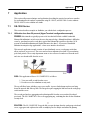
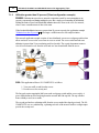
The SINGLEstream Link Aggregation Taps provide a superior solution for 24x7 monitoring of
full-duplex Ethernet links. Traditional Ethernet taps enable full-duplex monitoring of all traffic on a
network segment, but they transmit the data to the network tools (e.g. analyzers, IDSs, probes) in
two separate half-duplex streams. This not only requires each network tool to have two network
interface cards (NIC), but also requires that the tool be capable of combining and processing both
streams of data in order to monitor both sides of the conversation. Not all network tools have that
capability. The SINGLEstream Series faultlessly combine the two data streams, allowing any
connected network device/tool to receive a full-duplex stream of data with one NIC.
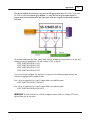
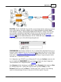
Additionally, the SINGLEstream Series provide a unique feature to help manage network
resources - multiple input/output ports or Any-to-Any ports. With extra Any-to-Any ports, more
network tools (such as analyzers and intrusion detection devices) can receive the same full-duplex
transmission, so there will never be contention for access to the network segment. Also, these ports
can be configured as more input ports to include more network segments for monitoring.
The SINGLEstream Series are adaptable with hard-wired In-Line taps and Any-to-Any ports
which can be configured with the Command Line Interface (CLI) to be used as input or output
portsto fit your needs and adapt with your ever-changing network.
© 2012 Datacom Systems Inc
12
2.3
SS-1200-S, SS-2200-S and SS-4200-S Series Link Aggregating Taps
What Shipped?
SS-1200-S Series Link Aggregation Taps
1 — Model: SS-1200-S series Link Aggregation Tap
2 — Switching AC Adapters
2 — AC Line Cords
1 — DRL512-2M-R serial cable, DB9 M/F straight thru
SS-2200-S Series Dual-Link Aggregation Taps
1 — Model: SS-2200-S series Dual-Link Aggregation Tap
2 — Switching AC Adapters
2 — AC Line Cords
1 — DRL512-2M-R serial cable, DB9 M/F straight thru
SS-4200-S Series Quad-Link Aggregation Taps
1 — Model: SS-4200-S series Quad-Link Aggregation Tap
2 — Switching AC Adapters
2 — AC Line Cords
1 — DRL512-2M-R serial cable, DB9 M/F straight thru
2.4
SINGLEstream™ Series Features and Benefits
Connect any protocol analyzers, probes, or intrusion detection systems for permanent InLine monitoring of full-duplex links — eliminates the need for network connectors to be
disconnected and connected each time a segment needs to be monitored.
Secure Shell (SSH) allows data to be exchanged using a secure channel between two
networked devices.
Simple Network Management Protocol (SNMP ) protocol for managing devices on IP
networks.
LINKprotect , proven industry leading, non-intrusive, fault-tolerant, transparent to the
network – will not interfere with data.
Support full-duplex and half-duplex.
Multiple input/output or Any-to-Any ports allow more network devices or tools to
simultaneously monitor the same link, providing extended security and analysis options, while
eliminating contention for network access. Also, these ports can be configured as more input
ports to include more networks segments for monitoring.
Redundant power ensures uninterrupted monitoring by eliminating power as a single point of
failure — you get seamless monitoring even if the main power source is unavailable.
Easy to install – optional rack mount available in 2 unit rack mount chassis (RMC-2) 1U
high.
© 2012 Datacom Systems Inc
Overview
13
Installed Management RJ45 port and Serial DB9 port allow for complete configuration
through a simple, easy to use Command Line Interface (CLI).
Datacom Customer Service Support is available via:
Phone: +1 315 463-9541
Website: www.datacomsystems.com
2.5
SINGLEstream™ Series Common Specifications
Management Port (front): RJ45 @ 100 Mbps Full-Duplex
The factory configured IP Address, Subnet Mask and Default Gateway are as follows:
IP Address: 192.168.1.1
Subnet Mask: 255.255.0.0
Default Gateway: 192.168.1.0
Fiber Tap Split Ratio and Insertion Loss (front): 50/50 — 4dB/4dB
Serial Port (rear): DB9
Power Requirement: Two external power adapters
Input: 100 - 240VAC 50 - 60Hz, 0.4-0.2 A — Output: 5VDC, 2.5A
Certified : CE, UL, CUL, CSA, TUV, CCC, PSE, JET, EU RoHS and China RoHS
Power Consumption: 12W
BTU/h: 40.9
Operating Temperature: 32º to 104° F — 0º to 40° C
Storage Temperature: -22º to 149° F — -30º to 65° C
Operating Range Relative Humidity: 5 to 90% non-condensing
Dimensions (H x W x D): includes RMC-2 rack mount bracket
1.750 x 7.950 x 7.775 inch
4.44 x 20.19 x 19.75 cm
Weight: 1.5 lbs; shipping: 6.5 lbs — 0.68 kg; shipping; 2.95 kg
© 2012 Datacom Systems Inc
14
2.6
SS-1200-S, SS-2200-S and SS-4200-S Series Link Aggregating Taps
SS-1200 Series Model Specific Specifications
SS-1204BT-BT-S:
Tap Connection: 1 - 10/100/1000BaseT In-Line (RJ45 Connectors)
Any-to-Any Ports: 2 - 10/100/1000BaseT (RJ45 Connectors)
SS-1204BT-SFP-S:
Tap Connection: 1 - 10/100/1000BaseT In-Line (RJ45 Connectors)
Any-to-Any Ports: 2 - SFP*
SS-1204LX-BT-S:
Tap Connection: 1 - 1000LX fiber In-Line (LC Connectors)
Any-to-Any Ports: 2 - 10/100/1000BaseT (RJ45 Connectors)
SS-1204LX-SFP-S:
Tap Connection: 1 - 1000LX fiber In-Line (LC Connectors)
Any-to-Any Ports: 2 - SFP*
SS-1204SX-BT-S:
Tap Connection: 1 - 1000SX fiber In-Line (LC Connectors)
Any-to-Any Ports: 2 - 10/100/1000BaseT (RJ45 Connectors)
*SFP = Small Form Pluggable can be LX, SX or 1000Mbs copper
(Support Datacom supplied only)
IMPORTANT: All BT taps can be configured to have traffic, for example TCP resets,
injected from Any-to-Any ports.
Note: Tap Connection = 2 ports (TAP)
2.7
SS-2200 Series Model Specific Specifications
SS-2206BT-BT-S:
Tap Connections: 2 - 10/100/1000BaseT In-Line (RJ45 Connectors)
Any-to-Any Ports: 2 - 10/100/1000BaseT (RJ45 Connectors)
SS-2206SX-SFP-S:
Tap Connections: 2 - 1000SX fiber In-Line (LC Connectors)
Any-to-Any Ports: 2 - SFP*
SS-2210BT-SFP-S:
Tap Connections: 2 - 10/100/1000BaseT In-Line (RJ45 Connectors)
Any-to-Any Ports: 4 - 10/100/1000BaseT (RJ45 Connectors)
Any-to-Any Ports: 2 - SFP*
*SFP = Small Form Pluggable can be LX, SX or 1000Mbs copper
(Support Datacom supplied only)
IMPORTANT: All BT taps can be configured to have traffic, for example TCP resets,
injected from Any-to-Any ports.
Note: Tap Connections = 4 ports (TAP 1 and TAP 2)
© 2012 Datacom Systems Inc
Overview
2.8
15
SS-4200 Series Model Specific Specifications
SS-4210BT-SFP-S:
Tap Connections: 4 - 10/100/1000BaseT In-Line (RJ45 Connectors)
Any-to-Any Ports: 2 - SFP*
*SFP = Small Form Pluggable can be LX, SX or 1000Mbs copper
(Support Datacom supplied only)
IMPORTANT: All BT taps can be configured to have traffic, for example TCP resets,
injected from Any-to-Any ports.
Note: Tap Connections = 8 ports (TAP 1, TAP 2, TAP 3 and TAP 4)
© 2012 Datacom Systems Inc
Hardware
3
17
Hardware
Front panel images of the SS-1200-S, the SS-2200-S and the SS-4200-S series are provided in
this section.
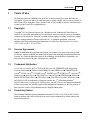
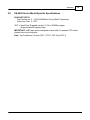
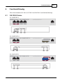
3.1
SS-1200 Series Front Panels
SS-1204BT-BT-S
SS-1204BT-SFP-S
SS-1204LX-BT-S
SS-1204LX-SFP-S
SS-1204SX-BT-S
© 2012 Datacom Systems Inc
18
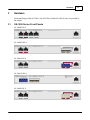
3.2
SS-1200-S, SS-2200-S and SS-4200-S Series Link Aggregating Taps
SS-2200 Series Front Panels
SS-2206BT-BT-S
SS-2206SX-SFP-S
SS-2210BT-BT/SFP-S
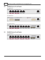
3.3
SS-4200 Series Front Panels
SS-4210BT-SFP-S
© 2012 Datacom Systems Inc
Hardware
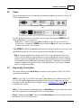
3.4
19
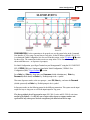
Front Panel Description
This section provides a illustration and description of the front panel of the SS-1200-S, SS-2200-S
and SS-4200-S series.
An explanation of each front panel legend follows:
3.4.1
Power
Two switching AC adapter power supplies are provided for each configurable unit. Although only
one power supply is required to power the module, use of a second independent power source is
strongly recommended to assure uninterrupted monitoring. Furthermore, connecting the second AC
input power socket to a different external power source circuit than the first AC input power source
eliminates power as a single point of failure. The power barrel sockets are located on the rear.
The POWER 1 and 2 front panel LEDs illuminate green when power is available at
both of the two rear power barrel sockets indicating power 1 and 2, respectively, are
on. Either LED not illuminated indicates a defective power source and immediate
investigation as to the cause is required to insure redundant power integrity.
3.4.2
TAP Ports
BT - TAP
BT - TAP (SS-1204BT-S port 1 and port 2) or TAP 1 and TAP 2 (SS-2206BT-S port 1 and port
2; port 3 and port 4) or TAP 1, TAP 2, TAP 3, and TAP 4 (SS-4210BT-S port 1 and port 2; port 3
and port 4; port 5 and port 6; port 7 and port 8) are RJ45 connectors used for connection to
network segments. These jacks have integrated LEDs that display line status and line speed of each
port. See the TAP LED Display Code table for LED display codes.
IMPORTANT: All BT taps can be configured to have traffic, for example TCP resets, injected from
Any-to-Any ports.
© 2012 Datacom Systems Inc
20
SS-1200-S, SS-2200-S and SS-4200-S Series Link Aggregating Taps
LX-BT/SX-BT - TAP (SS-1204LX-BT-S and SX-BT-S port 3 and port 4) are dual-duplex LC
connectors for connection to network segments. The LEDs to the right of the dual-duplex LC
connectors are solid green when a light level link has been detected by the respective TAP Rx port.
LX-SFP/SX-SFP - TAP (SS-1204LX-SFP-S and port 1 and port 2) or TAP 1 (SS-2206SX-SFPS port 1 and port 2) and TAP 2 (SS2206-SX-SFP-S port 5 and port 6) are dual-duplex LC
connectors for connection to network segments. The left LEDs below the dual-duplex LC
connectors are solid green when a light level link has been detected by the respective TAP Rx port.
The right LEDs solid green indicates 1,000 Mbs link speed.
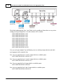
3.4.3
Any-to-Any Ports
Superuser assigned INPUT or OUTPUT ports. See Serial and Management Port - Command Line
Interface - Superuser Commands - 'SET PORT MONITOR (SE 34
Ports: 1 to 2 (SS-1204LX-BT-S or SS-1204SX-BT-S ):
Ports: 3 to 4 (SS-1204BT-BT-S):
Ports: 5 to 6 (SS-2206BT-BT-S):
Ports: 5 to 8 (SS-2210BT-BT-S):
are RJ45 connectors used for connection to network devices or tools. These jacks have integrated
LEDs that display line status and line speed of each port. See the Any-to-Any RJ-45 LED Display
Code table for LED display codes.
Ports: 3 to 4 (SS-1204BT-SFP-S, SS-1204LX-SFP-S and SX-SFP-S, SS-2206SX-SFP-S):
Ports: 9 to 10 (SS-2210BT-SFP-S):
Ports: 9 to 10 (SS-4210BT-SFP):
are sockets used with a small form-factor plug (SFP) module for connection to network devices or
tools. They can be connected through fiber or copper, or a mix of each.
© 2012 Datacom Systems Inc
Hardware
21
LX-BT/SX-BT - The LEDs located to the right of the SFP connectors are solid green indicating a link
has been detected between the respective Any-to-Any Rx port and network device/tool Tx port or
network segment. The LEDs are flashing green when data is passed.
LX-SFP/SX-SFP - The LED located below and slightly left of center of the SFP connectors are solid
green indicating a link has been detected between the respective Any-to-Any Rx port and network
device/tool Tx port or network segment. The LED flashes green when data is passed. The LED
located below and slightly right of center of the SFP connectors indicates the line speed of each
port. See the Any-to-Any SFP LED Display Code table for LED display codes.
3.4.4
Management Port
The MANAGEMENT PORT is an RJ45 socket used for 100 Mbs full-duplex connection with a
straight-through LAN cable via your management LAN to a Remote Management Console which is
a standard PC using any Telnet terminal emulation application.
Link indicates connection. The LED Display Code table deciphers the RJ45 jacks with integrated
LEDs that display line status of the MANAGEMENT PORT.
3.5
Rear Panel Description
This section provides a description of the rear panel of the SS-1200-S, SS-2200-S and SS-4200-S
series.
Either:
or
An explanation of each rear panel legend follows:
© 2012 Datacom Systems Inc
22
3.5.1
SS-1200-S, SS-2200-S and SS-4200-S Series Link Aggregating Taps
Serial DB9
The SERIAL connector port is a shielded DB9 Female and is cabled to the COM port of any
compatible network tool or PC where terminal emulation software resides. The cable is a parallel
straight-through cable (EIA232 Standard, DRL512-2M-R serial cable, DB9 M/F straight thru) with
no cross-overs or self-connects in the connector hoods. The SERIAL connector port is the only port
that can easily connect the Management PC to set the IP address (default 192.168.1.1) for the first
time. This drawing shows the DB9 Female Pin Assignment:
3.5.2
Power Switch (SFP series)
The front panel POWER 1, POWER 2 LEDs are illuminated green, respectively, when the DC power
switch is depressed ON and DC power is available at both the two rear DC power sockets. Either
POWER 1, POWER 2 LED illuminated red indicates a defective power source and immediate
investigation as to the cause is required to insure redundant power integrity.
3.5.3
Rear Label (BT series)
Identifiers for DB9, Serial Number (SN), Media Access Control (MAC) address, certification
compliance, input power requirements and various other information is provided.
3.5.4
Rear Labeling (SFP series)
Identifiers for Serial Number (SN), Media Access Control (MAC) address, certification
compliance, input power requirements and various other information is provided.
3.5.5
Input Power
Two DC input power sockets are provided on the rear panel. The front panel POWER 1 and 2
LEDs are illuminated green, respectively:
(SFP series) - when the DC POWER switch is depressed ON and DC power is available at
both the two rear DC power sockets; or
(BT series) - when DC power is available at both the two rear DC power sockets.
Either POWER 1 or 2 LED not illuminated when powered, indicates a defective power source and
immediate investigation as to the cause is required to insure redundant power integrity.
Although only one switching AC adapter power supply is required to power the configurable unit,
use of a second independent power source is strongly recommended to assure uninterrupted
monitoring. Furthermore, connecting the second DC input power socket to a different external
power source circuit than the first DC input power source eliminates power as a single point of
failure.
© 2012 Datacom Systems Inc
Initial Configuration
4
23
Initial Configuration
IMPORTANT: Prior to initial configuration of the hardware, it is imperative to review the
entire Initial Configuration section before proceeding to the Installation section.
NOTE: HyperTerminal is the preferred terminal emulation program and Microsoft© DOS-Windows
Telenet is the preferred Telnet client.
This section explains the considerations and requirements for the initial configuration of the SS1200-S, SS-2200-S and SS-4200-S series by a Command Line Interface (CLI) with a
management PC using a terminal emulation application connected either through the SERIAL DB9
port or though the MANAGEMENT RJ45 port. Only one configuration session can be open at a time.
4.1
Command Line Interface (CLI)
The Command Line Interface (CLI ) is used to:
set IP address (default 192.168.1.1), Subnet Mask (default 255.255.0.0) and Default
Gateway (default 192.168.1.0)
set port speed and duplex
enables the user to select which ports or groups of ports receive the data stream copies
allows Any-to-Any ports to be configured as either inputs or outputs.
The factory default for all Any-to-Any ports on all aggregation taps (SS-1200-S, SS-2200S and SS-4200-S series) are turned off by default - i.e. they are not set up as either inputs or
outputs and are not replicated to any other ports with the exception of the hard-wired inline taps.
It is strongly recommended that the entire Initial Configuration section be reviewed before
proceeding with installation.
4.1.1
Basic Functionality
Window Size Functionality: The CLI window has a limited number of character spaces available
(24 lines per screen, 80 characters per line). If more data than can fit is presented, the number of
lines is one less and a “—more—” prompt is shown on the last line.
Character Handling: Printable characters (ASCII codes 32-126) and non-printable codes noted
below:
Non-Printable Character
<enter key>
<backspace key>
Description
Executes command; places command in history buffer
Erases previous character entry; removes history buffer entry
Connectivity/Authentication Functionality: Connectivity to the configurable product is made
through the Management RJ45 or Serial DB9 port and authentication is required. This password
protection yields read-only access. To make configuration changes, Superuser (SU) mode must be
accessed with another password. See the 'Superuser Commands 31 ' section for more information.
© 2012 Datacom Systems Inc
24
SS-1200-S, SS-2200-S and SS-4200-S Series Link Aggregating Taps
Base Prompt: This is the text presented to the user logging in to use the CLI (default values
shown). All Usernames and passwords are case-sensitive.
Enter Username: Administrator
Enter Password: admin
>
Superuser log in:
Example: > SU
Enter Password: password
#
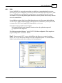
4.1.2
Password Recovery
Password Recovery is provided for a user that has forgotten the Superuser and/or Administrator
login password. Password recovery is accomplished by connecting to the unit serially using a
HyperTerminal like program and rebooting the unit. As the power-up sequence is occurring, depress
<Control> <C> and a text recovery key will be generated and displayed prior to the prompt. This
key is used to reset the passwords. An example recovery key prompt is: 617A6185774$
You must call Datacom Service Center with this recovery key in order to obtain the required
response to reset passwords. Given a valid reset response, the factory default passwords will be
saved in Non-Volatile memory. If an invalid response is given, a new recovery key will be calculated
and displayed at the prompt, as described above, after first clearing the screen.
4.1.3
Basic Commands (Read Only Access)
The following section shows the long form of the basic command set with the shortcut for the
command noted in parenthesis. All commands, either the exact long form or the shortcut form, are
entered after the prompt (default >) at the cursor. No auto-fill mode is available. After a brief
command overview, each function is followed by an example (Example: >) command input.
4.1.3.1
EXIT (EX)
This command use will exit the CLI shell as shown:
> EXIT (EX)
Example:
> EX
Connection to host lost.
Press any key to continue . . .
4.1.3.2
HELP (HE) or (?)
When this command is entered, a list of commands, their shortcut inputs, and their descriptions will
display. For the use and application of each command, refer to the individual command description
within this section. The HELP command displays the available commands depending upon the
specific product and not in ascending order as shown:
© 2012 Datacom Systems Inc
Initial Configuration
Example: > ?
Available commands:
ADD USER
DELETE USER
EDIT USER
EXIT
HELP
POWER STATUS
SET DATE
SET GATEWAY
SET IP
SET LINK PROTECT
SET PING
SET PORT GROUP
SET PORT MONITOR
SET PORT NAME
SET PORT SPEED
SET PORT VTAG
SET PORT VTAP
SET PROMPT
SET SNMPv3
SET SNMPv3 SUPERUSER
SET SSH
SET SSH KEY
SET SUBNET
SET TCP PORT
SET TELNET
SET TIME
SET UPGRADE
SHOW
SHOW GROUPS
SHOW MANAGEMENT
SHOW PORT CONFIG
SHOW PORT ROUTING
SHOW PRODUCT
SHOW TIME
SHOW USERS
SU
SU SET PASSWORD
4.1.3.3
AD US
DE US
ED US
EX
HE / ?
PO ST
SE DA
SE GA
SE IP
SE LP
SE PI
SE PO GR
SE PO MO
SE PO NA
SE PO SP
SE PO VT
SE PO VP
SE PR
SE V3
SE V3 SU
SE SH
SE SH KY
SE SU
SE TC PO
SE TE
SE TI
SE UP
SH
SH GR
SH MA
SH PO CO
SH PO RO
SH PR
SH TI
SH US
SU
SU SE PA
Add User
Delete User
Change Username/Password
Exit Shell
Show Help
Show Power Supply Status
Set System Date
Set Default Gateway
Set IP [subnet mask] [default gateway]
Set Link Protect parameters
Set Ping ON or OFF
Set Group Name
Set Monitor Configuration
Set Port Name (max 32 bytes)
Set Port Speed
Set Port VTAG Stripping
Set Port VTAP
Set Command Prompt (max 32 bytes)
Set SNMP ON or OFF
Set SNMP SuperUser Parameters
Set SSH ON or OFF
Set SSH Key
Set Subnet Mask nnn.nnn.nnn.nnn
Set TCP Port
Set Telnet ON or OFF
Set System Time
Set Upgrade ON or OFF
Show All Current Configurable Values
Show Group Configuration
Show Management Configuration
Show Port Configuration
Display Routing Summary
Show Product Name and Serial Number
Show System Date and Time
Display Users
Enter Superuser Mode
Set Superuser Password
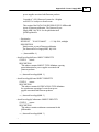
POWER STATUS (PO ST)
This command displays power supply status. It is entered and displays data as shown:
> POWER STATUS (PO ST)
Example: > PO ST
Power Supply 1: Good
Power Supply 2: Good
>
© 2012 Datacom Systems Inc
25
26
4.1.3.4
SS-1200-S, SS-2200-S and SS-4200-S Series Link Aggregating Taps
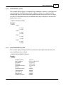
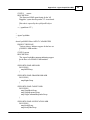
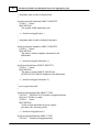
SHOW (SH)
Using this command alone, displays general information about the product as shown:
> SHOW (SH)
Example:
> SH
Date/Time:
Product:
Serial Number:
Version:
Security Version
MAC Address:
IP Address:
IP Subnet:
IP Default Gateway:
IP Port:
FlashUtils protocol:
Telnet protocol:
SSH protocol:
Ping protocol:
SNMPv3 protocol:
TAP 1:
1: t1-p1
2: t1-p2
TAP 2:
1: t2-p1
2: t2-p2
TAP 3:
1: t3-p1
2: t3-p2
TAP 4:
1: t4-p1
2: t4-p2
02-24-2011 16:38:31
SS-4210BT-SFP-S
9326023
5.3.1.4
1.0.0.14
00-14-e2-00-10-d3
192.168.1.1
255.255.0.0
192.168.1.0
2370
enabled
enabled
enabled
enabled
enabled
>
The following SHOW commands, with other qualifiers, displays more specific information:
© 2012 Datacom Systems Inc
Initial Configuration
4.1.3.5
27
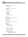
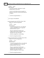
SHOW GROUPS (SH GR)
This command displays all ports as designated by the administrator (Superuser) as belonging to the
same logical group. Specifically, groups can be configured as if they were a single logical port,
enabling a high degree of control during both the initial setup and all subsequent moves or changes.
The GROUP NAME followed by the ports included in the group are displayed. It is entered and
displays data as shown:
> SHOW GROUPS (SH GR)
Example:
> SH GR
TAP 1:
1: t1-p1
2: t1-p2
TAP 2:
1: t2-p1
2: t2-p2
TAP 3:
1: t3-p1
2: t3-p2
TAP 4:
1: t4-p1
2: t4-p2
>
4.1.3.6
SHOW MANAGEMENT (SH MA)
This command displays Management RJ45 port information and authentication information. It is
entered and displays data as shown:
> SHOW MANAGEMENT (SH MA)
Example:
> SH MA
Security Version:
MAC Address:
IP Address:
IP Subnet:
IP Default Gateway:
IP Port:
FlashUtils protocol:
Telnet protocol:
SSH protocol:
Ping protocol:
SNMPv3 protocol:
>
© 2012 Datacom Systems Inc
1.0.0.12
00-14-e2-00-10-d3
192.168.1.1
255.255.0.0
192.168.1.0
2370
enabled
enabled
enabled
enabled
enabled
28
4.1.3.7
SS-1200-S, SS-2200-S and SS-4200-S Series Link Aggregating Taps
SHOW PORT CONFIG (SH PO CO)
This command displays all configurable related data for all ports. It is entered and displays data as
shown:
> SHOW PORT CONFIG (SH PO CO)
Example:
> SH PO CO
01: t1-p1
CFG: Auto Negotiate Current: No Link
LinkProtect OFF
Type: Tap (1..2)
Group Member: TAP 1
Copies to: 2
VLAN TAG Stripping: OFF
02: t1-p2
CFG: Auto Negotiate Current: No Link
LinkProtect OFF
Type: Tap (2..1)
Group Member: TAP 1
Copies to: 1
VLAN TAG Stripping: OFF
03: t2-p1
CFG: Auto Negotiate Current: No Link
LinkProtect OFF
Type: Tap (3..4)
Group Member: TAP 2
Copies to: 4
VLAN TAG Stripping: OFF
04: t2-p2
CFG: Auto Negotiate Current: No Link
LinkProtect OFF
Type: Tap (4..3)
Group Member: TAP 2
Copies to: 3
VLAN TAG Stripping: OFF
05: t3-p1
CFG: Auto Negotiate Current: No Link
LinkProtect OFF
Type: Tap (5..6)
Group Member: TAP 3
Copies to: 6
VLAN TAG Stripping: OFF
06: t3-p2
© 2012 Datacom Systems Inc
Initial Configuration
CFG: Auto Negotiate Current: No Link
LinkProtect OFF
Type: Tap (6..5)
Group Member: TAP 3
Copies to: 5
VLAN TAG Stripping: OFF
07: t4-p1
CFG: Auto Negotiate Current: No Link
LinkProtect OFF
Type: Tap (7..8)
Group Member: TAP 4
Copies to: 8
VLAN TAG Stripping: OFF
08: t4-p2
CFG: Auto Negotiate Current: No Link
LinkProtect OFF
Type: Tap (8..7)
Group Member: TAP 4
Copies to: 7
VLAN TAG Stripping: OFF
09: Mon1
CFG: Auto Negotiate Current: 1G Full Duplex
Type: Span
Group Member:
Copies to:
VLAN TAG Stripping: OFF
10: Mon2
CFG: Auto Negotiate Current: 1G Full Duplex
Type: Span
Group Member:
Copies to:
VLAN TAG Stripping: OFF
>
© 2012 Datacom Systems Inc
29
30
4.1.3.8
SS-1200-S, SS-2200-S and SS-4200-S Series Link Aggregating Taps
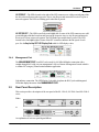
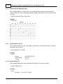
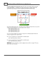
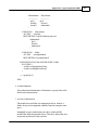
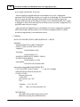
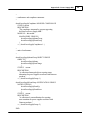
SHOW PORT ROUTING (SH PO RO)
This command displays, as a quick check, a port routing interface matrix for all ports in a brief
summary format. It is entered and displays, in this example, a stand-alone SS-4210BT-SFP-S data
as shown:
> SHOW PORT ROUTING (SH PO RO)
Example:
> SH PO RO
Outputs
01 02 03 04 05 06 07 08 09 10
01 --------X-----------------------------------------02 ---X----------------------------------------------03 -------------------X------------------------------04 --------------X-----------------------------------05 ------------------------------X-------------------06 ------------------------X-------------------------07 ----------------------------------------X---------08 -----------------------------------X--------------09 ---------------------------------------------------10 --------------------------------------------------->
4.1.3.9
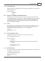
SHOW PRODUCT (SH PR)
This command displays the name, serial number, and firmware version of the product. It is entered
and displays data as shown:
> SHOW PRODUCT (SH PR)
Example:
> SH PR
Product:
Serial Number:
Version:
SS-4210BT-SFP-S
9326023
5.3.1.2
4.1.3.10 SHOW TIME (SH TI)
This command displays the set date and time for the product, it is entered as shown:
> SHOW TIME (SH TI)
Example:
> SH TI
Date/Time
10-09-2007 12:40:25
© 2012 Datacom Systems Inc
Initial Configuration
31
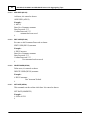
4.1.3.11 SHOW USERS (SH US)
Displays all users for the configurable product. The response asterisk indicates the connected user.
SHOW USERS (SH US)
Example: # SH US
* Administrator
username
4.1.4
Superuser Commands (Configuration Access)
The following section shows the long form of the Superuser command with the shortcut for the
command noted in parenthesis. A brief overview of the command display function is given followed
by an example (Example: #) command input. All commands, either the exact long form of the
command or the shortcut form of the command, are entered after the prompt (default #) at the
cursor. No auto-fill mode is available.
4.1.4.1
SU (SU)
This command accesses the Superuser mode where the product can be configured. A password
prompt is displayed and the default password is “password.” Then the Superuser prompt is
displayed except the prompt has turned from “>” to “#,” as shown below:
> SU (SU)
Enter Password: ********
#
4.1.4.2
SU SET PASSWORD (SU SE PA)
Change the password used to access Superuser mode. It is entered as shown:
SU SET PASSWORD (SU SE PA)
Example: # SU SE PA
***Warning***
Modification of the SU password has serious consequences if the password is lost!!
***Warning***
# Enter Password: ********
# Confirm Password: ********
#
4.1.4.3
SET PROMPT (SE PR)
This command, followed by a text string, changes the Base Prompt to the text value entered (up to
32 characters). It is entered as shown:
# SET PROMPT (SE PR) prompt text
Example: # SE PR Datacom
Datacom#
© 2012 Datacom Systems Inc
32
4.1.4.4
SS-1200-S, SS-2200-S and SS-4200-S Series Link Aggregating Taps
ADD USER (AD US)
Add users, it is entered as shown:
ADD USER (AD US)
Example:
# AD US
Enter New Username: username
Enter Password: ****
Confirm Password: ****
username has been saved.
#
4.1.4.5
EDIT USER (ED US)
Re-enter or edit Usernames/Passwords as shown:
EDIT USER (ED US) username
Example:
# ED US newuser
Enter New Username: username
Enter Password: ****
Confirm Password: ****
User username has been saved
#
4.1.4.6
DELETE USER (DE US)
Delete users, it is entered as shown:
DELETE USER (DE US) username
Example:
# DE US username
User "username" deleted
#
4.1.4.7
SET DATE (SE DA)
This command sets the real time clock date. It is entered as shown:
SET DATE (MMDDYY)
Example:
# SE DA 011311
#
© 2012 Datacom Systems Inc
Initial Configuration
4.1.4.8
33
SET TIME (SE TI)
This command, followed by the time (HHMMSS), sets the real time clock time. It is entered as
shown:
SET TIME (HHMMSS)
Example: # SE TI 033526
#
4.1.4.9
SET IP (SE IP), SUBNET (SU), GATEWAY (GA)
This command configures the IP address (default 192.168.1.1) parameter. Initially this should be
done using the serial port with a terminal application. The parameter is entered as shown:
# SET IP (SE IP) [IP Address nnn.nnn.nnn.nnn]
Example 1:
# SE IP 172.169.50.134
IP will be updated at end of session.
#
Or, the parameters can also be entered jointly, (i.e., IP Address [default 192.168.1.1], Subnet
Mask [default 255.255.0.0], Default Gateway [default 192.168.1.0]) but entry must be in the
proper sequence order and separated by a space delimiter, as shown:
# SET IP [SUBNET] [GATEWAY] nnn.nnn.nnn.nnn nnn.nnn.nnn.nnn nnn.nnn.nnn.nnn
# SET IP [SUBNET] [GATEWAY] nnn.nnn.nnn.nnn^nnn.nnn.nnnnnn^
# SET IP [SUBNET] [GATEWAY] nnn.nnn.nnn.nspacennn.nnn.nnspace
Example 2:
# SE IP 172.169.50.134 255.255.0.0 172.169.50.1
IP will be updated at end of session.
Subnet Mask will be updated at end of session.
Default Gateway will be updated at end of session.
#
4.1.4.10 SET SUBNET (SE SU)
This command configures the Subnet Mask (default 255.255.0.0) parameter. Initially this should be
done using the serial port with a terminal application. The parameter is entered as shown:
SET SUBNET (SE SU) [nnn.nnn.nnn.nnn]
Example:
# SE GA 172.169.50.1
Subnet Mask will be updated at end of session.
#
© 2012 Datacom Systems Inc
34
SS-1200-S, SS-2200-S and SS-4200-S Series Link Aggregating Taps
4.1.4.11 SET GATEWAY (SE GA)
This command configures the Gateway (default 192.168.1.0) parameter. Initially this should be done
using the serial port with a terminal application. The parameter is entered as shown:
SET GATEWAY (SE GA) [nnn.nnn.nnn.nnn]
Example:
# SE GA 172.169.50.1
Default Gateway will be updated at end of session.
#
4.1.4.12 SET PORT GROUP (SE PO GR)
Create a port list under a common name for ease of use. When displayed, the common name is all
caps, regardless of case entry. As part of this command, there is a command separator
(CONTAINS) or, if the OFF parameter (delete the group) is used, the CONTAINS is not used. A
maximum of 10 groups is allowed.
NOTE: PORT GROUP is shown within the SHOW GROUPS (SH GR) or the SHOW PORT
CONFIG (SH PO CO) display.
Groups as designated by the administrator (Superuser) belong to the same logical group.
Specifically, groups can be configured as if they were a single logical port, enabling a high degree of
control during both the initial setup and all subsequent moves or changes. It is entered as shown:
SET PORT GROUP (SE PO GR) name [OFF] or [CONTAINS] port list
Example:
# SE PO GR Monitor 1 CONTAINS 9,10
#
4.1.4.13 SET PORT MONITOR (SE PO MO)
This command sets the data routing by selecting the port (output) on which the monitoring device is
to be located as well as ports (input TAPS, SPAN) to be redirected to that monitor port. As part of
this command, there is a command separator (FROM) or, if the OFF parameter (turn off all data
routing to the selected port) is used, the FROM is not used.
NOTE: PORT MONITOR is shown within the SHOW PORT CONFIG (SH PO CO) or the
SHOW PORT ROUTING (SH PO RO) display.
It is entered as shown:
SET PORT MONITOR (SE PO MO) comma separated list of port numbers, port names or group
names [OFF] or [FROM comma separated list of port numbers, port names or group names]
Example 1:
# SE PO MO Port1 FROM Engineering
#
© 2012 Datacom Systems Inc
Initial Configuration
35
Example 2:
# SE PO MO 4 FROM 3,2,PortNine
#
Example 3:
# SE PO MO 3 OFF
#
NOTE: See the 'Exercise - CLI Setting Ports 50 ' and 'Application 69 ' sections for further
explanation and examples using input and output settings for tap and Any-to-Any ports.
4.1.4.14 SET PORT NAME (SE PO NA)
This command, followed by the port number or port name, a command separator (TO), then the
name text (up to 32 characters), assigns the new name text entered.
NOTE: PORT NAME is shown within the SHOW PORT CONFIG (SH PO CO) display.
It is entered as shown:
SET PORT NAME (SE PO NA) port number or port name TO name text
Example:
# SE PO NA 4 TO Port 4
#
4.1.4.15 SET PORT SPEED (SE PO SP)
This command changes the port speed for a single port or a group of ports.
NOTE: PORT SPEED is shown within the SHOW PORT CONFIG (SH PO CO) display.
It is entered as shown:
SET PORT SPEED (Comma separated list of Port numbers, port names, or group names) Speed
duplex is one of the following: 10HALF, 10FULL, 100HALF, 100FULL, 1000FULL, AUTO.
Example:
# SE PO SP 10 1000FULL
#
4.1.4.16 SET PORT VTAG (SE PO VT)
This command is used to change the capability of a port to either pass VLAN Tags or strip them
from a frame and recalculate the CRC of the frame as shown:
SE PO VT (Comma separated list of port numbers, port names, or group names) ON/OFF
Example: # SE PO VT 1,4,6,7 ON
#
© 2012 Datacom Systems Inc
36
SS-1200-S, SS-2200-S and SS-4200-S Series Link Aggregating Taps
4.1.4.17 SET LINK PROTECT (SE LP)
This command configures the link protect function for the integrated tap.
SET LINK PROTECT (SE LP) tapnum enable int1 int2 recovery where:
tapnum
specific tap number (1 or 2)
enable
Link Protect ON/OFF
int1
fail polling interval 1-3600 secs
int2
recover polling interval 1-3600 secs
recovery
AUTO/MANUAL
NOTE: The status of LINK PROTECT is shown within the SHOW PORT CONFIG (SH PO
CO) display.
Factory default is that link protect enable is ON, int1 and int2 is 10 seconds and recovery is
AUTO. If one side of the network traffic, through the integrated tap, is interrupted ("LINK"
dropped) for longer than 10 seconds, the tap will enter bypass mode and the other side of the
network will also drop "LINK" with the integrated tap. The TAP will continue to auto recover, as
heard when the bypass relays cycle at the polling interval rate, until link is established or the LINK
PROTECT settings are changed to different values.
# SET LINK PROTECT (SE LP) tapnum enable interval recovery
For example, for a SS-1210BT-BT/SFP, the parameters may be entered as shown:
Example:
# SE LP 1 ON 30 30 AUTO
#
This example command sets the TAP 1 ports (ports 1 and 2) to enable link protect ON, the polling
interval is set to 30 seconds and recovery is set to AUTO.
NOTE: Several common conditions could cause the LINK PROTECT function to initiate
bypass mode:
Prior to the installation of the integrated TAP in an active network; with the factory default
LINK PROTECT settings; and when LINK is not established within the 10 second polling
interval — the LINK PROTECT function will initiate bypass mode.
If one side of the network link is interrupted for longer than the current polling interval —
LINK PROTECT function will initiate bypass mode.
When recovery (AUTO/MANUAL) is set to MANUAL, the TAP will remain in bypass mode once
network link is interrupted through the polling interval. LINK is re-established at the Command Line
Interface (CLI) by re-executing the SET LINK PROTECT command. The bypass mode can also
be reset and LINK re-established by power cycling the TAP.
© 2012 Datacom Systems Inc
Initial Configuration
37
4.1.4.18 SET TCP PORT (SE TC PO)
This command configures the TCP Port (default 2370) parameter. Initially this should be done using
the serial port with a terminal application. The parameter is entered as shown:
SET TCP PORT (SE TC PO) [nnnnn]
Example:
# SE TC PO 17216
TCP Port is now updated.
#
4.1.4.19 SET UPGRADE (SE UP)
This command sets the FLASHutils service (default ENABLED) process. It is entered as shown:
SET UPDATE (SE UP) [OFF or ON]
Example 1:
# SE UP OFF
The FlashUtils protocol is now disabled.
#
Example 2:
# SE UP ON
The FlashUtils protocol is now enabled.
#
4.1.4.20 SET TELNET (SE TT)
This command sets the TELNET service (default ENABLED) process. It is entered as shown:
SET TELNET (SE TT) [OFF or ON]
Example 1:
# SE TT OFF
The Telnet protocol will be disabled at end of session.
#
Example 2:
# SE TT ON
The Telnet protocol will be enabled at end of session.
#
© 2012 Datacom Systems Inc
38
SS-1200-S, SS-2200-S and SS-4200-S Series Link Aggregating Taps
4.1.4.21 SET SSH (SE SH)
This command sets the SSH service (default ENABLED) process. It is entered as shown:
SET SSH (SE SH) [OFF or ON]
Example 1:
# SE SH OFF
The SSH protocol will be disabled at end of session.
#
Example 2:
> SE SH ON
The SSH protocol will be enabled at end of session.
#
4.1.4.22 SET SSH KEY (SE SH KY)
This command sets the SSH service (default ENABLED) process. It is entered as shown:
SET SSH KEY (SE SH KY) [RSA or DSA]
RSA and DSA are algorithms for public-private-key cryptography. Cut and paste the PEM (Privacy
Enhanced Mail) encoded RSA or DSA key.
Example 1:
# SE SH KY RSA
Please cut & paste the PEM encoded rsa SSH key . . . <--right mouse click if Putty or Terra Term
rsa SSH Key successfully loaded
#
Example 2:
> SE SH KY DSA
Please cut & paste the PEM encoded dsa SSH key . . . <--right mouse click if Putty or Terra Term
dsa SSH Key successfully loaded
#
4.1.4.23 SET PING (SE PI)
SET PING ENABLE (SE PI EN): This command enables or disables PING (default ENABLED)
service process. It is entered as shown:
SET PING ENABLE (SE PI EN) [OFF or ON]
Example 1:
# SE PI EN OFF
The PING protocol is now disabled.
#
Example 2:
# SE PI EN ON
The PING protocol is now disabled.
#
© 2012 Datacom Systems Inc
Initial Configuration
39
4.1.4.24 SET SNMPv3 (SE V3)
This command sets the SNMP service (default ENABLED) process. It is entered as shown:
SET SNMPv3 (SE V3) [OFF or ON]
Example 1:
# SE V3 OFF
The SNMP protocol is now disabled.
#
Example 2:
> SE V3 ON
The SNMP protocol is now enabled.
#
4.1.4.25 SET SNMPv3 SUPERUSER (SE V3 SU)
SET SNMPV3 SUPERUSER (SE V3 SU) name auth authPass priv privPass: This command is
required to create an SNMP V3 user. There MUST be at least one SNMP user for the feature to
work. It is entered as shown:
SET SNMPV3 SUPERUSER (SE V3 SU) name auth authPass priv privPass
where:
name
auth
authPass
priv
privPass
SNMP principal [maximum of 32 characters]
MD5/SHA [authorization encryption type]
authorization password - at least 12 characters
DES/AES [privilege encryption type]
privilege password - at least 12 characters
Example:
> SE V3 SU username MD5 12characters DES characters12
SNMP V3 user created
© 2012 Datacom Systems Inc
40
4.2
SS-1200-S, SS-2200-S and SS-4200-S Series Link Aggregating Taps
SERIAL Port Configuration (DB9)
Use of the SERIAL DB9 port, which is fairly simple and straight forward, is strongly recommended
for initial configuration of the hardware.
4.2.1
HyperTerminal
NOTE: HyperTerminal is the preferred terminal emulation program.
Any freely available terminal emulator may be utilized, but please note the specific HyperTerminal
setup if using an alternate terminal emulator. Once connection is made to the SERIAL DB9 port,
open the HyperTerminal connection with the following settings:
9600 bits per second
8 data bits
Parity none
1 stop bit
Flow control none
After completing review of the Command Line Interface (CLI) 23 and Exercise - CLI setting Ports
50 sections, IP Address configuration can be found in the IP Address Configuration 42 section.
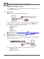
4.3
MANAGEMENT Port Configuration (RJ45)
NOTE: HyperTerminal is the preferred terminal emulation program and Microsoft© DOS-Windows
Telenet is the preferred Telnet client.
The factory configured IP Address, Subnet Mask and Default Gateway are as follows:
IP Address: 192.168.1.1
Subnet Mask: 255.255.0.0
Default Gateway: 192.168.1.0
© 2012 Datacom Systems Inc
Initial Configuration
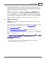
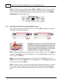
4.3.1
41
HyperTerminal
NOTE: HyperTerminal is the preferred terminal emulation program.
Any freely available terminal emulator may be utilized, but please note the specific HyperTerminal
setup if an alternate terminal emulator is used
IMPORTANT: For Host Address, if initial IP Address HAS NOT BEEN configured, use 192.168.1.1
(default) or if initial IP Address HAS BEEN configured, use the Local Area Network address input
during initial IP Address configuration.
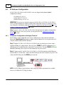
HyperTerminal (terminal emulator) enter:
TCP/IP (Winsock)
Host Address: nnn.nnn.nnn.nnn [i.e., 192.168.1.1 or Local Area Network]
Port Number: 23
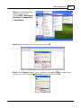
Set HyperTerminal (terminal emulator) properties
Under File>Properties>Settings
Emulation: VT100
Under File>Properties>Settings>ASCII Setup
Check box: Send line ends with line feeds
Check box: Echo typed characters locally
After completing review of the Command Line Interface (CLI) 23 and Exercise - CLI setting Ports
50 sections, IP Address configuration can be found in the IP Address Configuration 42 section.
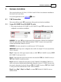
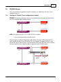
4.3.2
TELNET
NOTE: Microsoft© DOS-Windows Telenet is the preferred Telnet client.
Most network equipment and operating systems with a TCP/IP stack also support some kind of
TELNET service server for remote configuration. Security-related shortcomings have limited
TELNET (TErminaL NETwork) usage, although TELNET is still widely used when diagnosing
problems, manually "talking" to other services without specialized client software, and administration
of network elements such as integration and maintenance of core network elements.
IMPORTANT: For hostname, if initial IP Address HAS NOT BEEN configured, use 192.168.1.1
(default) or if initial IP Address HAS BEEN configured, use the Local Area Network address setting
input during initial IP Address configuration.
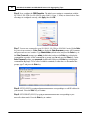
TELNET using MANAGEMENT RJ45 - software configuration of the hardware
At the Windows command prompt enter:
telnet
At the Microsoft Telnet> prompt enter:
o nnn.nnn.nnn.nnn (open hostname) [i.e., o 192.168.1.1 or Local Area Network])
After completing review of the Command Line Interface (CLI) 23 and Exercise - CLI setting Ports
50 sections, IP Address configuration can be found in the IP Address Configuration 42 section.
© 2012 Datacom Systems Inc
42
4.4
SS-1200-S, SS-2200-S and SS-4200-S Series Link Aggregating Taps
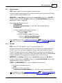
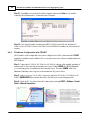
IP Address Configuration
All SS-1200-S, SS-2200-S and SS-4200-S series are shipped with a factory default
configuration as follows:
IP Address:192.168.1.1
Subnet Mask: 255.255.0.0
Default Gateway: 192.168.1.0
IMPORTANT: If you expect to remotely connect to the SS-1200-S, SS-2200-S or SS-4200-S
series, you must change the IP Address, Subnet Mask and Default Gateway to match your Local
Area Network as described in either the 'IP Address Configuration with HyperTerminal 42 ' or 'IP
Address Configuration with TELNET 46 ' sections.
Note: If your SS-1200-S, SS-2200-S or SS-4200-S already has the IP Address, Subnet Mask
and Default Gateway set for your network, you may proceed to the 'Small Form-Factor Plug
Module 58 ' section.
4.4.1
IP Address Configuration with HyperTerminal
The IP address of the configurable series can be configured via a serial connection with either
Microsoft's HyperTerminal application (available on most Windows PCs) or an open source free
software terminal emulator for MS-Windows.
Step 1. Plug the SS-1200-S, SS-2200-S or SS-4200-S into an external power source using a
supplied switching AC adapter and AC line cord. Note, POWER 1 or 2 LED is illuminated green
indicating power is available from the connected DC power socket. The other POWER LED is not
illuminated, indicating a lack of power to the unconnected DC power socket.
Step 2. Connect your PC and SS-1200-S, SS-2200-S or SS-4200 using the provided Datacom
Systems DRL512-2M-R cable. Connect the DB9 Female pin end to the serial port on your PC and
connect the DB9 Male pin to the SERIAL port on the unit.
NOTE: For PCs without 9-pin serial ports, check with your product representative for available
sources of a USB to RS-232 Plug-in Adapter.
© 2012 Datacom Systems Inc
Initial Configuration
43
Step 3. Open the HyperTerminal
application on your PC by
selecting START > All Programs >
Accessories > Communications
> HyperTerminal
Step 4. Name a new HyperTerminal connection and select OK
Step 5. On the Connect to window, create a serial link by selecting the COM port assigned to the
serial port on your PC from the Connect using: pull-down menu and select OK
© 2012 Datacom Systems Inc
44
SS-1200-S, SS-2200-S and SS-4200-S Series Link Aggregating Taps
Step 6. Next, configure the COM Properties. The initial correct settings to communicate with the
SS-1200-S, SS-2200-S or SS-4200-S series (9600, 8, None, 1, None) are shown below. Once
all settings are configured correctly, click Apply, then click OK.
Step 7. You are now connected to your SS-1200-S, SS-2200 or SS-4200-S series. Hit the Enter
key twice in succession (i.e., Enter, Enter) to display the Enter Username: prompt. All Usernames
and passwords are case-sensitive. Type Administrator (default value) and press the Enter key. At
the Enter Password: prompt, type admin (default value) and press the Enter key to display the
command line > prompt. At the command line > prompt, type su and press the Enter key. At the
Enter Password: prompt, type password (default value) and press the Enter key to display the
command line # prompt. To see a list of available commands, at either the > or # command line
prompt, type ? and press the Enter key.
Step 8. SET IP (SE IP) by typing se ip xxx.xxx.xxx.xxx corresponding to a valid IP address for
your network. Press the Enter key to continue.
Step 9. SET SUBNET (SE SU) by typing se su xxx.xxx.xxx.xxx corresponding to your
network's subnet mask. Press the Enter key to continue.
© 2012 Datacom Systems Inc
Initial Configuration
45
Step 10. SET GATEWAY (SE GA) (if needed) by typing se ga xxx.xxx.xxx.xxx corresponding
to your network's default gateway. Press the Enter key to continue.
Step 11. SHOW (SH) by typing sh and press the Enter key to display and affirm that the pending
IP Address, IP Subnet and IP Default Gateway match the intended Local Area Network input IP
Address, IP Subnet and IP Default Gateway.
Step 12. If the pending IP Address is not correct, repeat Step 8, if the pending IP Subnet is not
correct, repeat Step 9 and if the pending IP Default Gateway is not correct, repeat Step 10.
Repeat Step 11 to review and verify that the pending IP Address, IP Subnet and IP Default
Gateway match the intended Local Area Network input IP Address, IP Subnet and IP Default
Gateway.
© 2012 Datacom Systems Inc
46
SS-1200-S, SS-2200-S and SS-4200-S Series Link Aggregating Taps
Step 13. Type exit to save the network address changes and press the Enter key to end the
connection session indicated by 'Connection closed' response.
Step 14. Close HyperTerminal, disconnect the DRL512-2M-R serial cable and install the SS1200-S series, SS-2200-S series or SS-4200-S series SINGLEstream in your chosen network
location.
4.4.2
IP Address Configuration with TELNET
The IP address of the configurable series can be configured via a RJ45 connection with a TELNET
application (available on most Windows PCs) or an open source free software terminal emulator for
MS-Windows.
Step 1. Connect the SS-1200-S, SS-2200-S or SS-4200-S with one of the supplied switching AC
adapters and AC line cords into an external power source. Either POWER 1 or 2 LED illuminates
green indicating power is available from the connected source. The other POWER LED is not
illuminated, indicating a lack of power to the unconnected DC power socket.
Step 2. Using a cross-over Cat 5e cable, connect one end to the SS-1200-S, SS-2200-S or SS4200-S MANAGEMENT port and the other end to the RJ45 port on your management PC.
Step 3. Check the PC Local Area Network Connection by selecting START > Settings > Control
Panel > Network Connections
© 2012 Datacom Systems Inc
Initial Configuration
47
Step 4. Right click Local Area Connection and from drop down menu select Properties. Highlight
Internet Protocol (TCP/IP) and highlight and click Properties box. Check the button Use the
following IP Address: Use IP Address: 192.168.1.5 and Subnet Mask: 255.255.255.0. Click OK.
Step 5. Open the Command Prompt on your PC by selecting START > All Programs >
Accessories > Command Prompt
© 2012 Datacom Systems Inc
48
SS-1200-S, SS-2200-S and SS-4200-S Series Link Aggregating Taps
Step 6. In the Command Prompt window, at the prompt, enter TELNET and hit the Enter key. (To
see a list of available Microsoft Telnet Client Commands, at the prompt, enter ? and hit the Enter
key. Supported commands will be displayed.)
Step 7. At the Command Prompt window prompt, enter o 192.168.1.1 and hit the Enter key.
Step 8. You are now connected at the Enter Username: prompt. Usernames and passwords are
case-sensitive. Type Administrator (default value) and press the Enter key. At the Enter
Password: prompt, type admin (default value) and press the Enter key to display the command
line > prompt. At the command line > prompt, type su and press the Enter key. At the Enter
Password: prompt, type password (default value) and press the Enter key to display the command
line # prompt. To see a list of available commands, at either the > or # command line prompt, type ?
and press the Enter key .
Step 9. SET IP (SE IP) by typing se ip xxx.xxx.xxx.xxx corresponding to a valid IP address for
your network. Press the Enter key to continue.
Step 10. SET SUBNET (SE SU) by typing se su xxx.xxx.xxx.xxx corresponding to your
network's subnet mask. Press the Enter key to continue.
Step 11. SET GATEWAY (SE GA) (if needed) by typing se ga xxx.xxx.xxx.xxx corresponding
to your network's default gateway. Press the Enter key to continue.
© 2012 Datacom Systems Inc
Initial Configuration
49
Step 12. SHOW (SH) by typing sh and press the Enter key to display and affirm that the pending
IP Address, IP Subnet and IP Default Gateway match the intended Local Area Network input IP
Address, IP Subnet and IP Default Gateway.
Step 13. If the pending IP Address is not correct, repeat Step 9, if the pending IP Subnet is not
correct, repeat Step 10 and if the pending IP Default Gateway is not correct, repeat Step 11.
Repeat Step 12 to review and verify that the pending IP Address, IP Subnet and IP Default
Gateway match the intended Local Area Network input IP Address, IP Subnet and IP Default
Gateway.
Step 14. Type exit and press the Enter key to save the network address changes which ends the
connection session as indicated in a few seconds by .the Windows informational message balloon
pop-up icon "Local Area Connection - A network cable is unplugged."
Step 15. Close TELNET
Step 16. Disconnect the DRL512-2M-R serial cable.
Step 17. Install the SS-1200-S, SS-2200-S or SS-4200-S series in your chosen network location.
© 2012 Datacom Systems Inc
50
4.5
SS-1200-S, SS-2200-S and SS-4200-S Series Link Aggregating Taps
Exercise - CLI Setting Ports
PREMISE: The configurable SINGLEstream series' allow multiple network devices/tools to
receive the combined data of multiple Ethernet network segments. The SINGLEstream series has
hard-wired in-line network taps. However, any of the remaining Any-to-Any ports can be
configured as shown in this exercise and additional examples are shown in the 'Application SS1200-S series 69 and SS-2200-S series 75 ' section.
GOAL/SOLUTION: The exercise for the setup of a SS-1210BT-BT/SFP-S shown is as follows:
Ports 1 and 2 are a hard-wired in-line tap.
Ports 3 and 4 are a hard-wired in-line tap
Port 5 has been setup to output data to a Network IDS from Port 4’s input.
Port 6 has been setup to output aggregated data to a Probe from Port 3 and 4’s inputs.
Port 7 has been setup to output data to a Network IDS from Port 1’s input and returns TCP
resets from the Network IDS.
Port 8 has been setup to output data to a Network IDS from Port 2’s input and returns TCP
resets from the Network IDS.
Port 9 has been setup to output aggregated data to a Network IDS from Port 1 and 2’s inputs/
outputs and returns TCP resets from the Network IDS.
Port 10 has been setup to output aggregated data to a Probe from Port 1, 2, 3, and 4’s inputs.
NOTE: Port 9’s Network IDS’s network interface card (NIC) can handle both sides of the
network conversation at once. Port 7 and 8’s Network IDS’s network interface cards cannot
handle the whole conversation at once and must use two separate NICs for each side of the
conversation. It can be setup either way to fit your network devices/tools’ requirements.
© 2012 Datacom Systems Inc
Initial Configuration
51
CONFIGURATION: For the connections to be properly set, use the syntax below in the Command
Line Interface (CLI) to setup Tap and Any-to-Any ports. As the IP address (default 192.168.1.1)
is set during the 'Initial Configuration' it is not covered in this section, see the 'IP Address 42 ' section
for those steps. The connections in this exercise are setup in the CLI as shown below (syntax is
shown with either user > or Superuser # prompts):
For Initial Configuration, open HyperTerminal on your Management PC using the SS-1210BT-BT/
SFP-S SERIAL DB9 port. Settings are found in the 'Initial Configuration', 'SERIAL Port
Configuration (DB9)', 'HyperTerminal 40 ' section.
Press Enter key, Enter key, then enter your Username (default: Administrator), Enter key,
Password (default: admin) and Enter key. Default prompt is the > symbol.
Then enter Superuser mode, at the user prompt >, enter SU, Enter key, and enter the Password
(default: password) and Enter key. Default prompt is the # symbol.
In Superuser mode use the following syntax for the different connections. This syntax sets the input/
output for Any-to-Any ports as well as the input/output for Tap ports.
The factory default for all aggregation taps (SS-1200-S series and SS-2200-S series) are
turned off by default - i.e. they are not set up as either inputs or outputs and are not
replicated to any other ports with the exception of the hard-wired in-line taps.
© 2012 Datacom Systems Inc
52
SS-1200-S, SS-2200-S and SS-4200-S Series Link Aggregating Taps
The default configuration has Ports 1 and 2 hard-wired as an inline tap Ensure there are no previous
settings present, go through Ports 1-10 and set them to OFF as shown:
# SET PORT MONITOR 1 OFF
# SET PORT MONITOR 2 OFF
# SET PORT MONITOR 3 OFF
# SET PORT MONITOR 4 OFF
# SET PORT MONITOR 5 OFF
# SET PORT MONITOR 6 OFF
# SET PORT MONITOR 7 OFF
# SET PORT MONITOR 8 OFF
# SET PORT MONITOR 9 OFF
# SET PORT MONITOR 10 OFF
Now you can begin setting the Tap and Monitor ports as to which port inputs the data and which
ports aggregate and/or output the data.
Port 1 is set as output for Ports 7, 8 and 9’s input which is set with this syntax:
# SET PORT MONITOR 1 FROM 7,8,9
Port 2 is set as output for Ports 7, 8 and 9’s input which is set with this syntax:
# SET PORT MONITOR 2 FROM 7,8,9
Port 5 is set as output for Port 4’s input which is set with this syntax:
# SET PORT MONITOR 5 FROM 4
Port 6 is set as output for Ports 3 and 4’s input which is set with this syntax:
# SET PORT MONITOR 6 FROM 3,4
© 2012 Datacom Systems Inc
Initial Configuration
53
Port 7 is set as output for Port 1’s input/output which is set with this syntax:
# SET PORT MONITOR 7 FROM 1
Port 8 is set as output for Port 2’s input/output which is set with this syntax:
# SET PORT MONITOR 8 FROM 2
Port 9 is set as output for Ports 1 and 2’s input/output which is set with this syntax:
# SET PORT MONITOR 9 FROM 1,2
Port 10 is set as output for Ports 1, 2, 3, and 4’s input which is set with this syntax:
# SET PORT MONITOR 10 FROM 1,2,3, 4
As a quick check, show port routing interface matrix with this syntax:
# SH PO RO
Outputs
01 02 03 04 05 06 07 08 09 10
01 ------------X--------------------------------X-----------X-----X
02 ------X---------------------------------------------X----X-----X
03 ---------------------------------------X-------------------------X
04 ---------------------------------X----X-------------------------X
05 -------------------------------------------------------------------06 -------------------------------------------------------------------07 ------X-----------------------------------------------------------08 ------------X-----------------------------------------------------09 ------X----X-----------------------------------------------------10 -------------------------------------------------------------------#
This completes the exercise using the Command Line Interface for setting ports.
4.6
Management Connection (RJ45)
Once installation of the Link Aggregation Tap has been completed in your chosen network location,
see Hardware Installation 61 section, management connection is initiated over the network via either
TELNET or SSH as explained in the following section.
© 2012 Datacom Systems Inc
54
4.6.1
SS-1200-S, SS-2200-S and SS-4200-S Series Link Aggregating Taps
TELNET
Note: For security, TELNET can be disabled using the Command Line Interface.
IMPORTANT: For hostname, if initial IP Address HAS BEEN configured, as is the case shown below,
use the Local Area Network address setting input during initial IP Address configuration. Otherwise,
if initial IP Address HAS NOT BEEN configured, see the Management Module Connection 40 section in
the Management (RJ45) 41 section.
TELNET using MANAGEMENT RJ45 - software configuration of the hardware
At the Windows command prompt enter:
telnet
At the Microsoft Telnet> prompt enter:
o nnn.nnn.nnn.nnn (open hostname) [i.e., o Local Area Network IP]
Step 1. Open the Command Prompt on your PC by selecting START > All Programs >
Accessories > Command Prompt
Step 2. In the Command Prompt window, at the prompt, enter TELNET and hit the Enter key. (To
see a list of available Microsoft Telnet Client Commands, at the prompt, enter ? and hit the Enter
key. Supported commands will be displayed.)
Step 3. At the Command Prompt window prompt, enter o Local Area Network IP and hit the Enter
key.
Step 4. You are now connected at the Enter Username: prompt. Usernames and passwords are
case-sensitive. Type Administrator (default value) and press the Enter key. At the Enter
Password: prompt, type admin (default value) and press the Enter key to display the command
line > prompt. To see a list of available commands, at the > command line prompt, type ? and press
the Enter key .
Step 5. Type Exit and press the Enter key to end the connection session as indicated in a few
seconds by the Windows informational message balloon pop-up icon "Local Area Connection - A
network cable is unplugged."
Step 6. Close TELNET.
© 2012 Datacom Systems Inc
Initial Configuration
4.6.2
55
SSH
Secure Shell (SSH ) is a network protocol that uses public key cryptography that allows secure
network services to be exchanged over an insecure network between two networked devices. SSH
Secure Shell with its array of unmatched security features is an essential tool in today's network
environment. It is a powerful guardian against the numerous security hazards that nowadays threaten
network communications.
Several different versions of the Secure Shell client and server exist. Please note that the different
versions may use different implementations of the SSH protocol, and therefore you may not be able
to connect to an SSH1 server using SSH2 client software, or vice versa.
Restrictions for Secure Shell Version 2 Support:
Execution Shell and remote command execution are the only applications supported.
Compression is not supported.
The following instructions illustrate a "typical" PuTTY SSH client configuration. This example was
prepared using PuTTY version 0.60. PuTTY.
Step 1. When you start PuTTY, you see the dialog box that allows you to control everything
PuTTY can do. You don't need to change most of the configuration options. To start the simplest
kind of session, all you need to do is to enter a few basic parameters.
© 2012 Datacom Systems Inc
56
SS-1200-S, SS-2200-S and SS-4200-S Series Link Aggregating Taps
Step 2. In the Host Name (or IP address) box, enter the host name or IP address of the SSH
Server you want to connect to. Once you have filled in the Host Name (or IP address), Connection
type: [default: SSH] and possibly Port [default: 22] settings, you are ready to connect.
Step 3. Press the Open button at the bottom of the dialog box, and PuTTY will begin trying to
connect you to the server. If you are using SSH to connect to the SSH Server for the first time, you
will probably see a message looking something like this:
The warning message above asks you whether you want to trust this host key or not. This is a
feature of the SSH protocol, it is designed to protect against a network attack known as spoofing
which redirects your connection to a different computer, so that you send your password to the
wrong machine. To prevent this attack, each SSH Server has a unique identifying code, called a
host key. So if you connect to a SSH Server and it sends you a different host key from the one you
were expecting, you will have the chance to abandon your connection before you type any private
information (such as a password) into it.
© 2012 Datacom Systems Inc
Initial Configuration
57
Whether or not to trust the host key is your choice. Connecting within a company network, you
might feel that all the network users are on the same side and spoofing attacks are unlikely, so you
might choose to trust the key without checking it. Connecting across a hostile network (such as the
Internet) you should check with your system administrator.
Step 4. After you have connected, you will be asked to login as:, type Administrator (default
value) and press the Enter key. At the Administrator@hostname (or IP address)'s password:
prompt, type admin (default value) and press the Enter key to display the command line > prompt.
To see a list of available commands, at the > command line prompt, type ? and press the Enter key .
Step 5. Type Exit and press the Enter key to end the connection session. Close PuTTY.
4.7
SNMP Configuration
IMPORTANT: SNMP MUST be enabled and there MUST be at least one SNMP user for the
SNMP feature to work.
Once installation of the Link Aggregation Tap has been completed in your chosen network location,
if at least one SNMP user has not been created, refer to the CLI Command Set 24 to:
Step 1. SET SNMPv3 (SE V3)
39
[ON].
Step 2. SET SNMPV3 SUPERUSER (SE V3 SU)
39
name auth authPass priv privPass
Use your Network Management System to access the Link Aggregation Tap to perform GET, SET,
TRAP, etc. SNMP functions.
The Appendix A - Agent Capabilities MIB 81 , Appendix B - Power Supply MIB 89 and Appendix
C - Structure of Management MIB 103 sections are for your reference.
RELEASE NOTES:
1. When adding a TRAP destination, any specified snmpTargetAddrTagList string must be
restricted to alphanumeric characters (0-9, a-z, A-Z).
© 2012 Datacom Systems Inc
58
4.8
SS-1200-S, SS-2200-S and SS-4200-S Series Link Aggregating Taps
Small Form-Factor Plug Module
This section provides information about small form-factor plug (SFP) modules. The SFP modules
are input/output devices that plug into a Gigabit Ethernet (GE) small form-factor (SFF) port, linking
the port with a 1000Base-X fiber or 1000Base-T copper network.
The fiber SFP module have a receiver port (Rx) and a transmitter port (Tx) that make up one optical
interface.The 1000Base-SX (short wavelength) SFP module operates on standard multimode fiber
networks compliant with the 1000Base SX standard. The 1000Base-LX (long wavelength) SFP
module operates on standard single-mode fiber networks compliant with the 1000Base LX
standard. The fiber SFP module is a 1000 Mbps optical interface in the form of an LC-type duplex
port that supports interfaces compliant with the 1000Base-X standard.
The copper SFP module is compliant with the 1000Base-T standard and operates on standard
Category 5 wiring and has an RJ45 connector.
4.8.1
Intallation Prerequisites
This section describes safety and compliance guidelines you should observe before you install an
SFP module in your SS-1200-S, SS-2200-S or SS-4200-S series unit.
NOTE: You can install and remove SFP modules with power on to the system; however, it is
strongly recommended that you do not install or remove the SFP module with fiber or copper cables
attached to it. Disconnect all cables before removing or installing a SFP module.
CAUTION: Prevent system problems, use only Datacom Systems Inc. supplied SFP modules.
4.8.2
Safety Guidelines
Before handling a SFP module, observe the following guidelines:
Copper and fiber SFP modules are static-sensitive. To prevent electrostatic discharge (ESD)
damage, follow your normal ESD handling procedures.
Fiber SFP modules are dust-sensitive. When storing a SFP module or when a fiber cable is not
plugged in, always keep plugs in the SFP module optical hole.
The most common source of contaminants in the fiber SFP optical aperture is debris picked up on
the terminations of the optical connectors. Use an alcohol swab or lint-free absorbent wipes to
clean the terminations of the optical connector.
WARNING: Fiber SFP modules are class 1 laser and LED products. Invisible laser radiation
may be emitted from the port opening when no fiber cable is connected, avoid exposure to
laser radiation and do not stare in open optical ports.
© 2012 Datacom Systems Inc
Initial Configuration
4.8.3
59
Installing the SFP Module
SFP modules might ship already installed in your SS-1200-S, SS-2200, or they might arrive
packaged separately. This section describes how to install the SFP module.
NOTE: You can install SFP modules with power on to the system; however, it is strongly
recommended that you do not install the SFP module with fiber or copper cables attached to it.
Disconnect all cables before installing a SFP module.
CAUTION: Prevent system problems, use only Datacom Systems Inc. supplied SFP modules.
Step 1. Turn the SFP module so the latch is towards the center of the Gigabit Ethernet Interface
sockets. The SFP module is keyed so that it cannot be inserted incorrectly.
Step 2. Insert the SFP module into the SFF port and repeat Step 1 and Step 2 inserting other SFP
modules until completed.
Step 3. Attach the appropriate network cable to the LC-type or RJ45-type connector on the SFP
module. For fiber optic SFP modules you can use either simplex or duplex connectors. For simplex
connectors, two cables are required, one cable for transmit (Rx) and a second cable for receive
(Rx). For duplex connectors, only one cable that has both Tx and Rx connectors is required.
4.8.4
Removing the SFP Module
SFP modules might ship already installed in your SS-1200-S, SS-2200, or they might arrive
packaged separately. This section describes how to remove the SFP module.
NOTE: You can remove SFP modules with power on to the system; however, it is strongly
recommended that you do not remove the SFP module with fiber or copper cables attached to it.
Disconnect all cables before removing a SFP module.
Step 1. Disconnect the network cable from the SFP module LC-type or RJ45-type connector.
Step 2. Release the SFP module from the GE SFF port by moving the swing latch away from the
body of the unit.
Step 3. Slide the SFP module out of the GE SFF port.
© 2012 Datacom Systems Inc
Hardware Installation
5
61
Hardware Installation
This section describes the SS-1200-S, SS-2200-S and SS-4200-S series hardware installation at
the network site of your choice.
For specific applications see the 'Application 69 ' section.
5.1
TAP Connection
This section will focus on the TAP connection(s) of the typical series hardware installation.
5.1.1
Copper SS-1200BT-S and SS-2200BT-S series
1. This section describes the SS-1200BT-S or SS-2200BT-S copper TAP connection(s) of the
configurable series hardware installation.
WARNING: The copper TAP port is bidirectional Tx/Rx path sensitive. PRIOR TO POWERING
THE TAP, both end-device LINK LEDs must indicate “LINK” to ensure correct power fault
tolerant tap functionality during loss of power.
WARNING: 100 meters must not be exceeded between CAT 5E end-points.
IMPORTANT: All BT taps can be configured to have traffic, for example TCP resets, injected from
Any-to-Any ports.
Step 1. Connect one of the copper network cables to a RJ45 TAP (SS-1200BT-S series) or TAP 1
(SS-2200BT-S series) port socket.
Step 2. Connect the other copper network cable to the other RJ45 TAP (SS-1200BT-S series) or
TAP 1 (SS-2200BT-S series) port socket.
Step 3. End-device LINK LEDs must indicate “LINK” PRIOR TO POWERING THE TAP to
ensure correct power fault tolerant tap functionality during loss of power. If “LINK” does not exist,
the network connection is backwards. Reverse TAP (SS-1200BT-S series) or TAP 1 (SS-2200BTS series) port socket connections and “LINK” will be established.
Step 4. Repeat Step 1., Step 2. and Step 3. to connect TAP 2 of the SS-2200BT-S series to
another network.
© 2012 Datacom Systems Inc
62
SS-1200-S, SS-2200-S and SS-4200-S Series Link Aggregating Taps
TAP (SS-1200BT-S series port 1 and port 2) or TAP 1 and TAP 2 (SS-2200-S series port 1 and
port 2; port 3 and port 4) are RJ45 connectors used for connection to network segments. These
jacks have integrated LEDs that display line status and line speed of each port. See the TAP LED
Display Code table for LED display codes.
5.1.2
Fiber Optic SS-1200LX-S and SS-1200SX-S series
This section shows the fiber optic SS-1200LX-S or SS-2200SX TAP connection(s) of the typical
configurable series hardware installation.
Step 1. Connect one of the fiber optic duplex network cables to a TAP port socket. The LINK LED
associated with this TAP quad-LC socket illuminates green indicating light signal has been detected
on the respective Rx TAP port.
Step 2. Connect the other fiber optic duplex network cables to the other TAP port socket. The
LINK LED associated with this TAP quad-LC socket illuminates green indicating light signal has been
detected on the respective Rx TAP port.
TAP (SS-1200LX-S and SS-1200SX-S series port 9 and port 10) are dual-duplex LC connectors
used for connection to network segments. The LEDs located to the right of the dual-duplex LC
connectors are solid green indicating a light level link has been detected by the respective TAP Rx
port.
© 2012 Datacom Systems Inc
Hardware Installation
5.2
63
Power
This section describes the power connection at the network installation site of the SS-1200-S, SS2200-S configurable series.
or
Two DC input power sockets are provided on the rear panel. The front panel POWER 1 and 2
LEDs are illuminated green, respectively:
(BT series) - when DC power is available at both the two rear DC power sockets; or
(SFP series) - when the DC POWER switch is depressed ON and DC power is available at
both the two rear DC power sockets.
Either POWER 1 or 2 LED not illuminated when powered, indicates a defective power source and
immediate investigation as to the cause is required to insure redundant power integrity.
1. Step 1. Using the supplied Power Adapters and AC Line Cords, plug the SS-1200-S, SS2200-S series into different circuit external power sources.Although only one power supply is
required to power the configurable unit, use of a second independent power source is strongly
recommended to assure uninterrupted monitoring. Furthermore, connecting the second Power
Adapter to a different external power source circuit than the first AC power source eliminates
power as a single point of failure.
5.3
Any-to-Any Connection
This section will focus on the Any-to-Any port connection of the typical SS-1200-S, SS-2200-S
series hardware installation.
NOTE: For SS-1200-S, SS-2200-S series with a Gigabit Ethernet (GE) small form-factor (SFF)
port, the SFP modules might ship already installed in your unit, or they might arrive packaged
separately. See the 'Small Form-Factor Pluggable' section, 'Installing the SFP Module 59 ,' on how
to install the SFP module.
Step 1. Connect a network or monitoring cable to an Any-to-Any port socket and the other side of
this cable to the network or monitoring tool NIC port as appropriate..
Step 2. Continue repeating Step 1. for any remaining Any-to-Any port socket you want connected
from the SS-1200-S, SS-2200-S series.
© 2012 Datacom Systems Inc
64
SS-1200-S, SS-2200-S and SS-4200-S Series Link Aggregating Taps
These port sockets have integrated LEDs that display line status and line speed of each port. See
the Any-to-Any Port LED Display Code table for LED display codes.
5.4
Management Connection
This section shows the MANAGEMENT port 100 Mbs Full-Duplex connection of the typical SS1200-S, SS-2200-S configurable series hardware installation.
Step 1. Connect a network cable to the MANAGEMENT port RJ45 socket. The MANAGEMENT
port RJ45 left LED illuminates green when link has been established with the network. The
MANAGEMENT port right LED illuminates green when passing data.
The MANAGEMENT PORT is an RJ45 socket used for 100 Mbs full-duplex connection with a
straight-through LAN cable via your management LAN to a Remote Management Console which is
a standard PC using a Telnet terminal emulator software application.
Link indicates connection. The LED Display Code table deciphers the RJ45 jacks with integrated
LEDs that display line status of the MANAGEMENT PORT.
Related topics: 1) Management Connection (RJ45)
Configuration 57 .
53
, 2) Telnet
54
, 3) SSH
55
and 4) SNMP
© 2012 Datacom Systems Inc
Functional Drawing
6
Functional Drawing
This section contains the SS-1200-S, SS-2200-S and SS-4200-S series functional drawings.
6.1
SS-1200-S Series
SS-1204BT-BT-S
SS-1204BT-SFP-S
SS-1204LX-BT-S
© 2012 Datacom Systems Inc
65
66
SS-1200-S, SS-2200-S and SS-4200-S Series Link Aggregating Taps
SS-1204LX-SFP-S
SS-1204SX-BT-S
© 2012 Datacom Systems Inc
Functional Drawing
6.2
SS-2200-S Series
SS-2206BT-BT-S
SS-2206SX-SFP-S
SS-2210BT-BT/SFP-S
© 2012 Datacom Systems Inc
67
68
6.3
SS-1200-S, SS-2200-S and SS-4200-S Series Link Aggregating Taps
SS-4200-S Series
SS-4210BT-SFP
© 2012 Datacom Systems Inc
Application
7
69
Application
This section will present techniques and applications describing the practical use and new remedies
for performing network analysis requirements using SS-1200-S, and SS-2200-S series solutions.
The SS-4200-S series solutions are similar.
7.1
SS-1200 Series
This section describes examples to familiarize you with the basic configuration process.
7.1.1
Utilization less than 50 percent (HyperTerminal configuration example)
PREMISE: Most interfaces typically operate at far less than half of their available bandwidth.
Ethernet link utilization is at its lowest closest to the network edge. Although hard data is difficult to
come by, anecdotal research reveals that a typical fast Ethernet link operates at less than 10-20
percent of bandwidth utilization and Gigabit Ethernet at less than 5-10 percent of bandwidth
utilization in enterprise edge applications - where users interface the network.
This network application example consists of users distributed across a workgroup switch that
allows end users server access. The server and end users utilization is less than 50 percent during
peak load periods. The security department wants to view all server bound access from the users
and view user bound traffic from the server.
GOAL: This application will use a SS-1204BT-BT-S as follows:
1. View user traffic to and from the server.
2. Provide access for redundant security tools.
The tap will allow better visibility to user-server traffic. A power fault tolerant tap does not bring
down the network link if the tap fails. The first goal requires tapping the link between the workgroup
switch and the server.
The second goal involves aggregating and replicating traffic from the access method developed
previously. The SS-1204BT-BT-S acts as an aggregating tap, combining the data for the redundant
security tools.
SOLUTION: The SS-1204BT-BT-S taps the link, accepts the input from the workgroup switch and
server, aggregates and replicates the traffic to multiple ports for analysis and utilizes the factory
© 2012 Datacom Systems Inc
70
SS-1200-S, SS-2200-S and SS-4200-S Series Link Aggregating Taps
default LINK PROTECT settings. With the factory default LINK PROTECT settings, if one
side of the network traffic is interrupted for longer than 10 seconds, the tap will enter bypass mode
and the other side of the network will also drop "LINK" with the integrated tap. See the SET LINK
PROTECT 36 section for additional information. The SS-1204BT-BT-S has a built in tap on ports
1 and 2 which make copies of the traffic flowing through the unit.
Where the aggregate bandwidth exceeds capacity, drops are inevitable and then the application
where 'Utilization greater than 50 percent 72 ' should be considered as a solution..
CONFIGURATION: The IP address (default 192.168.1.1), Subnet Mask and Default Gateway is set
during the 'Initial Configuration' for your Local Area Network settings and will not be covered in this
section, see the 'IP Address Configuration with HyperTerminal 42 ' section for those steps. Use the
syntax below in the Command Line Interface (CLI) to setup Tap and Any-to-Any ports (syntax is
shown with either user > or Superuser # prompts):
For configuration, open HyperTerminal on your Management PC using the SS-1204BT-BT-S
SERIAL DB9 port. Settings are found in the 'Initial Configuration', 'SERIAL Port Configuration
(DB9)', 'HyperTerminal 40 ' section.
Press twice Enter key and Enter key. Enter Username (default: Administrator) and Enter key.
Enter Password (default: admin) and Enter key. Default prompt is the > symbol. Enter superuser
mode, type su and Enter key. Enter the Password (default: password) and Enter key. Default
prompt is the # symbol. Use the following syntax to set the input/output for Any-to-Any ports as
well as the output for Tap ports.
© 2012 Datacom Systems Inc
Application
71
The factory default for all Any-to-Any ports on all aggregation taps (SS-1200-S series and
SS-2200-S series) are turned off by default - i.e. they are not set up as either inputs or
outputs and are not replicated to any other ports with the exception of the hard-wired inline taps.
The default configuration has Ports 1 and 2 hard-wired as an inline tap. Ensure there are no previous
settings present, go through Ports 1-4 and set them to OFF as shown:
# SET PORT MONITOR 1 OFF
# SET PORT MONITOR 2 OFF
# SET PORT MONITOR 3 OFF
# SET PORT MONITOR 4 OFF
Now you can begin setting the Tap and Any-to-Any ports as to which port inputs the data and
which ports aggregate and/or output the data.
Port 3 is set as output for Port 1 and 2’s input which is set with this syntax:
# SET PORT MONITOR 3 FROM 1,2
Port 4 is set as output for Port 1 and 2’s input which is set with this syntax:
# SET PORT MONITOR 4 FROM 1,2
IMPORTANT: If desired, this BT tap could be configured to have traffic, for example TCP resets,
injected from Any-to-Any ports.
© 2012 Datacom Systems Inc
72
7.1.2
SS-1200-S, SS-2200-S and SS-4200-S Series Link Aggregating Taps
Utilization greater than 50 percent (Telnet configuration example)
PREMISE: Utilization increases due to network congestion caused by users attempting to use
capacity concurrently and fanning multiple devices into a single port contending for bandwidth.
Pushing the limits of speed and bandwidth utilization increases closer to the core of a network,
where a more constant stream of data is the norm.
When bandwidth utilization increases greater than 50 percent capacity, the application example
'Utilization less than 50 percent 69 ' is no longer a reliable answer to the analysis solution.
This network application example consists of users distributed across two workgroup switches that
allows end users access to the server farm via a server switch. The server switch and end users
utilization is greater than 50 percent during peak load periods. The security department wants to
view all server bound access from the users and view user bound traffic from the server.
GOAL: This application will use a SS-1204BT-BT-S as follows:
1. View user traffic to and from the servers.
2. Provide access for security tool.
The first goal requires tapping the link between the workgroup switch and the server switch. A
power fault tolerant tap does not bring down the network link if the tap fails. The tap will allow
better visibility to user-server traffic.
The second goal involves replicating traffic from the access method developed previously. The SS1204BT-BT-S acts as a standard tap, replicating each side of the network traffic to a single output
port for the security tool.
© 2012 Datacom Systems Inc
Application
73
SOLUTION: The SS-1204BT-BT-S taps the link, accepts the input from the workgroup switch and
server switch, replicates the traffic to multiple ports for analysis and utilizes the factory default
LINK PROTECT settings. With the factory default LINK PROTECT settings, if one side of the
network traffic is interrupted for longer than 10 seconds, the tap will enter bypass mode and the
other side of the network will also drop "LINK" with the integrated tap. See the SET LINK
PROTECT 36 section for additional information. The SS-1204BT-BT-S has a built in tap on ports
1 and 2 which make copies of the traffic flowing through the unit.
CONFIGURATION: The IP address (default 192.168.1.1), Subnet Mask and Default Gateway is set
during the 'Initial Configuration' for your Local Area Network settings and will not be covered in this
section, see the 'IP Address Configuration with TELNET 46 ' section for those steps. Use the syntax
below in the Command Line Interface (CLI) to setup Tap and Any-to-Any ports (syntax is shown
with either user > or Superuser # prompts):
For Configuration, open TELNET on your Management PC and open a hostname connection with
the SS-1204BT-BT-SMANAGEMENT RJ45 port. Settings are found in the 'Initial Configuration',
'MANAGEMENT Port Configuration (RJ45)', 'TELNET 41 ' section.
Enter Username (default: Administrator) and Enter key. Enter Password (default: admin) and Enter
key. Default prompt is the > symbol. Enter superuser mode, type su and Enter key. Enter
Password (default: password) and Enter key. Default prompt is the # symbol. Use the following
syntax to set the input/output for Any-to-Any ports as well as the output for Tap ports.
© 2012 Datacom Systems Inc
74
SS-1200-S, SS-2200-S and SS-4200-S Series Link Aggregating Taps
The factory default for all aggregation taps (SS-1200-S series and SS-2200-S series) are
turned off by default - i.e. they are not set up as either inputs or outputs and are not
replicated to any other ports with the exception of the hard-wired in-line taps.
The default configuration has Ports 1 and 2 hard-wired as an inline tap. Ensure there are no previous
settings present, go through Ports 1-4 and set them to OFF as shown:
# SET PORT MONITOR 1 OFF
# SET PORT MONITOR 2 OFF
# SET PORT MONITOR 3 OFF
# SET PORT MONITOR 4 OFF
Now you can begin setting the Tap and Any-to-Any ports as to which port inputs the data and
which ports aggregate and/or output the data.
Port 3 is set as output for Port 1’s input which is set with this syntax:
# SET PORT MONITOR 3 FROM 1
Port 4 is set as output for Port 2’s input which is set with this syntax:
# SET PORT MONITOR 4 FROM 2
IMPORTANT: If desired, this BT tap could be configured to have traffic, for example TCP resets,
injected from Any-to-Any ports.
© 2012 Datacom Systems Inc
Application
7.2
75
SS-2200 Series
This section describes an application example to familiarize you with the basic SS-2200-S series
configuration process.
7.2.1
Tapping the Firewall (Telnet configuration example)
PREMISE: This network application consists of two redundant routers that send outbound traffic to
one of two redundant high-availability firewalls
GOAL: This application will use a SS-2210BT-BT/SFP-S as follows:
1. Secure and analyze traffic from either firewall.
The goal requires securing and analyzing the traffic entering or leaving each firewall and not lose
either capability should one of the firewall fail. This is accomplished by tapping both links to each
firewall with a power fault tolerant tap. The Intrusion Detection System (IDS) and Protocol Analyzer
will each require two ports with the capability to aggregate streams of traffic together.
© 2012 Datacom Systems Inc
76
SS-1200-S, SS-2200-S and SS-4200-S Series Link Aggregating Taps
SOLUTION: The SS-2210BT-BT/SFP-S taps both links, aggregates traffic together and utilizes
factory default LINK PROTECT settings. Four ports (6 through 8) are setup to send nonaggregated traffic to other tools for redundancy. Ports 9 and 10 are small form pluggables that allow
outputs in either fiber or copper connectivity media. Since multiple device can all be configured to
receive the same data, the SS-2210BT-BT/SFP-S is perfect for product comparisons.
CONFIGURATION: The IP address (default 192.168.1.1), Subnet Mask and Default Gateway is set
during the 'Initial Configuration' for your Local Area Network settings and will not be covered in this
section, see the 'IP Address Configuration with TELNET 46 ' section for those steps. Use the syntax
below in the Command Line Interface (CLI) to setup Tap and Any-to-Any ports (syntax is shown
with either user > or Superuser # prompts):
For Configuration, open TELNET on your Management PC and open a hostname connection with
the SS-2210BT-BT/SFP-S MANAGEMENT RJ45 port. Settings are found in the 'Initial
Configuration', 'MANAGEMENT Port Configuration (RJ45)', 'TELNET 41 ' section.
Enter Username (default: Administrator) and Enter key. Enter Password (default: admin) and Enter
key. Default prompt is the > symbol. Enter superuser mode, type su and Enter key. Enter
Password (default: password) and Enter key. Default prompt is the # symbol. Use the following
syntax to set the input/output for Any-to-Any ports as well as the output for Tap ports.
The factory default for all Any-to-Any ports on all aggregation taps (SS-1200-S series and
SS-2200-S series) are turned off by default - i.e. they are not set up as either inputs or
outputs and are not replicated to any other ports with the exception of the hard-wired inline taps.
The default configuration has Ports 1, 2, 3 and 4 hard-wired as inline taps. Ensure there are no
previous settings present, go through Ports 1-10 and set them to OFF as shown:
#
#
#
#
#
#
#
#
#
#
SET PORT MONITOR 1 OFF
SET PORT MONITOR 2 OFF
SET PORT MONITOR 3 OFF
SET PORT MONITOR 4 OFF
SET PORT MONITOR 5 OFF
SET PORT MONITOR 6 OFF
SET PORT MONITOR 7 OFF
SET PORT MONITOR 8 OFF
SET PORT MONITOR 9 OFF
SET PORT MONITOR 10 OFF
© 2012 Datacom Systems Inc
Application
77
Now you can begin setting the ports as to which port inputs the data and which ports aggregate and/
or output the data.
Port 5 is set as output for 2’s input which is set with this syntax:
# SET PORT MONITOR 5 FROM 2
Port 6 is set as output for 1’s input which is set with this syntax:
# SET PORT MONITOR 6 FROM 1
Port 7 is set as output for Port 4’s input which is set with this syntax:
# SET PORT MONITOR 7 FROM 4
Port 8 is set as output for Port 3’s input which is set with this syntax:
# SET PORT MONITOR 8 FROM 3
Port 9 is set as output for Ports 1,2,3 and 4’s input/output which is set with this syntax:
# SET PORT MONITOR 9 FROM 1,2,3,4
Port 10 is set as output for Ports 1, 2, 3, and 4’s input which is set with this syntax:
# SET PORT MONITOR 10 FROM 1,2,3, 4
CONCLUSION: The SS-2210BT-BT/SFP-S provides the ability to tap two network segments,
selectively determine how the traffic is combined and to which ports. Maximum flexibility is
achieved, since both links can be aggregated together and sent to multiple output ports. Additional
ports are available for devices that do not need to see both links or when troubleshooting specific
links. Ports 9 and 10 provide small form pluggable outputs for devices with fiber media. With the
factory default LINK PROTECT settings, if one side of the network traffic, through the SS-2200S is interrupted for longer than 10 seconds, the tap will enter bypass mode and the other side of the
network will also drop "LINK" with the integrated tap. See the SET LINK PROTECT 36 section
for additional information.
© 2012 Datacom Systems Inc
Customer Service
8
79
Customer Service
This USERguide was written to help you get to know your new VS-1200 Series quickly and easily.
We would welcome any comments or suggestions you may have regarding this USERguide.
Datacom Customer Service is available via telephone, you may leave a voice message and our
Customer Service Staff will return your call as soon as possible. Datacom Customer Service is also
available via the Web.
Tel: +1 315 463-9541
Web: http://www.datacomsystems.com
8.1
Internet
Obtain additional information about Datacom Systems, Inc. at: http://www.datacomsystems.com
8.2
Warranty
See http://www.datacomsystems.com for warranty detailed information.
8.3
Limits of Liability
See http://www.datacomsystems.com for Limits of Liability detailed information.
© 2012 Datacom Systems Inc
Appendix A - Agent Capabilities MIB
9
Appendix A - Agent Capabilities MIB
The Datacom Agent Capabilities MIB
This Appendix specifies a proprietary MIB module of Datacom Systems
Inc.
Distribution of this memo is limited to Datacom product licensees
and other interested parties having express written consent from
Datacom Systems Inc.
MIB documentation may be requested by contacting us at:
http://www.datacomsystems.com.
Copyright Notice
Copyright (C) 2010 Datacom Systems Inc. All Rights Reserved; use is
subject to license terms.
Abstract
This memo defines a set of agent identities used to identify Datacom
SNMP agents and a set of agent capabilities used to convey the
capabilities of Datacom SNMP Agents.
Table of Contents
1. Introduction
2. The Internet-Standard SNMP Management Framework
3. Conventions
4. Overview of the Datacom Agent Capabilities MIB Module
4.1 Agent Identities
4.2 AGENT-CAPABILITIES statements
5. Definitions
6. Acknowledgments
7. Security Considerations
8. References
8.1 Normative References
8.2 Informative References
9. Change Log
1. Introduction
This memo defines a set of agent identities used to identify Datacom
© 2012 Datacom Systems Inc
81
82
SS-1200-S, SS-2200-S and SS-4200-S Series Link Aggregating Taps
SNMP agents and a set of agent capabilities used to convey the
capabilities of Datacom SNMP Agents.
2. The Internet-Standard SNMP Management Framework
For a detailed overview of the documents that describe the current
Internet-Standard Management Framework, please refer to section 7 of
RFC 3410 [RFC3410].
Managed objects are accessed via a virtual information store, termed
the Management Information Base or MIB. MIB objects are generally
accessed through the Simple Network Management Protocol (SNMP).
Objects in the MIB are defined using the mechanisms defined in the
Structure of Management Information (SMI). This memo specifies a
MIB module that is compliant to the SMIv2, which is described in STD
58, RFC 2578 [RFC2578], STD 58, RFC 2579 [RFC2579] and STD 58, RFC
2580 [RFC2580].
3. Conventions
The key words "MUST", "MUST NOT", "REQUIRED", "SHALL", "SHALL NOT",
"SHOULD", "SHOULD NOT", "RECOMMENDED", "MAY", and "OPTIONAL" in this
document are to be interpreted as described in [RFC2119].
4. Overview of the Datacom Agent Capabilities MIB Module
This MIB module contains OBJECT-IDENTITY definitions used to
identify Datacom SNMP agents and contains AGENT-CAPABILITIES
statements used to express the capabilities of Datacom SNMP agents.
Each set of definitions is described in the following sections.
4.1 Agent Identities
The identity of a Datacom SNMP agent is exposed as the value of the
sysObjectID object. For additional information about the definition
of sysObject, see the SNMPv2-MIB [RFC 3418].
Datacom agent identities are defined within the Datacom agentIdents
subtree.
Examples of sysObjectID values retrieved from a Datacom SNMP agent
by a management application include the following:
© 2012 Datacom Systems Inc
Appendix A - Agent Capabilities MIB
sysObjectID.0 = agentIdCopperConfigurables218
sysObjectID.0 = agentIdAllPluggables227
4.2 AGENT-CAPABILITIES statements
The capabilities of a Datacom SNMP agent are exposed as a set of
values in the sysORTable. For additional information about the
object definitions comprising the sysORTable, see the SNMPv2-MIB
[RFC 3418].
Datacom agent capabilities are defined within the Datacom agentCaps
subtree.
Refer to section 6, "Mapping of the AGENT-CAPABILITIES macro" in RFC
2580, "Conformance Statements for SMIv2" [RFC2580] for further
information on the use of agent capabilities statements by
management application and SNMP agents.
An example of values exposed in the sysORTable follows:
sysORID.1 = dcomCapsSNMPv3Base
sysORDescr.1 = "supports SNMPv3"
sysORUpTime.1 = 54
sysORID.2 = dcomCapsAres1dot0dot0
sysORDescr.2 = "supports Datacom ARES version 1.0.0"
sysORUpTime.1 = 55
5. Definitions
DATACOM-AGENT-CAPS-MIB DEFINITIONS ::= BEGIN
IMPORTS
MODULE-IDENTITY, OBJECT-IDENTITY
FROM SNMPv2-SMI
-- [RFC2578]
AGENT-CAPABILITIES
FROM SNMPv2-CONF
-- [RFC2580]
datacomMibs, agentIdents,
agentCaps
FROM DATACOM-SMI-MIB;
datacomAgentCapsMib MODULE-IDENTITY
LAST-UPDATED "201007260000Z" -- 26 July 2010, midnight
ORGANIZATION "Datacom Systems Inc."
© 2012 Datacom Systems Inc
83
84
SS-1200-S, SS-2200-S and SS-4200-S Series Link Aggregating Taps
CONTACT-INFO
"Datacom Systems Inc.
9 Adler Drive
East Syracuse, NY 13057
USA
Telephone: +1 315 463 1585
URL:
http://www.datacomsystems.com
"
DESCRIPTION
"The MIB module for defining agent identities and
agent capabilities for Datacom SNMP Agents.
Copyright (C) 2010 Datacom Systems Inc. All rights
reserved. Use is subject to license terms.
This version of the DATACOM-AGENT-CAPS-MIB module
is part of Datacom publication, `The Datacom Agent
Capabilities MIB', July 2010. See the publication
itself for full legal notices.
"
-- Revision log
REVISION
"201007260000Z" -- 26 July 2010, midnight
DESCRIPTION
"Initial version, as part of Datacom publication
'The Datacom Agent Capabilities MIB', July 2010.
"
::= { datacomMibs 3 }
--- Agent Identities
-agentIdCopperConfigurables218 OBJECT-IDENTITY
STATUS
current
DESCRIPTION
"The Datacom SNMP agent identity for the 'Copper
Configurables' system based upon the 218 circuit board.
This value is exposed by the sysObjectID object.
"
::= { agentIdents 218 }
agentIdAllPluggables227 OBJECT-IDENTITY
© 2012 Datacom Systems Inc
Appendix A - Agent Capabilities MIB
STATUS
current
DESCRIPTION
"The Datacom SNMP agent identity for the 'All
Pluggables' system based upon the 227 circuit board.
This value is exposed by the sysObjectID object.
"
::= { agentIdents 227 }
--- Agent Capabilities
-dcomCapsSNMPv3Base AGENT-CAPABILITIES
PRODUCT-RELEASE
"Various releases- Indicates support for the base set
of SNMPv3 MIB modules.
"
STATUS current
DESCRIPTION
"The Agent Capabilities statement indicating support
for the base set of SNMPv3 MIB modules.
"
SUPPORTS SNMP-MPD-MIB
INCLUDES {
snmpMPDGroup
}
SUPPORTS SNMP-FRAMEWORK-MIB
INCLUDES {
snmpEngineGroup
}
SUPPORTS SNMP-TARGET-MIB
INCLUDES {
snmpTargetBasicGroup,
snmpTargetResponseGroup,
snmpTargetCommandResponderGroup
}
SUPPORTS SNMP-NOTIFICATION-MIB
INCLUDES {
snmpNotifyGroup,
snmpNotifyFilterGroup
© 2012 Datacom Systems Inc
85
86
SS-1200-S, SS-2200-S and SS-4200-S Series Link Aggregating Taps
}
SUPPORTS SNMP-USER-BASED-SM-MIB
INCLUDES {
usmMIBBasicGroup
}
SUPPORTS SNMP-VIEW-BASED-ACM-MIB
INCLUDES {
vacmBasicGroup
}
SUPPORTS SNMPv2-MIB
INCLUDES {
snmpGroup,
snmpSetGroup,
systemGroup,
snmpBasicNotificationsGroup
}
::= { agentCaps 1 }
dcomCapsAres1dot0dot0 AGENT-CAPABILITIES
PRODUCT-RELEASE
"Datacom ARES version 1.0.0
"
STATUS current
DESCRIPTION
"The Agent Capabilities statement for Datacom ARES
version 1.0.0
"
SUPPORTS IF-MIB
INCLUDES {
ifGeneralInformationGroup,
linkUpDownNotificationsGroup
}
VARIATION
ifPhysAddress
ACCESS
not-implemented
DESCRIPTION "not implemented"
VARIATION
ifAdminStatus
ACCESS
read-only
DESCRIPTION "values change according to the
corresponding value of ifOperStatus
as follow:
© 2012 Datacom Systems Inc
Appendix A - Agent Capabilities MIB
ifAdminStatus ifOperStatus
------------- -----------up(1)
up(1)
down(2)
down(2)
down(3)
unknown(4)
"
VARIATION
ifOperStatus
ACCESS
read-only
DESCRIPTION "only the following states are
implemented:
up(1)
down(2)
unknown(4)
"
VARIATION
ifAlias
ACCESS
not-implemented
DESCRIPTION "not implemented"
SUPPORTS DATACOM-POWER-SUPPLY-MIB
INCLUDES {
dcomPowerSupplyStatusGroup,
dcomPowerSupplyEventGroup
}
::= { agentCaps 2 }
END
6. Acknowledgments
The production and maintenance of this memo is a group effort of the
Datacom development team.
7. Security Considerations
This module does not define any management objects. Instead, it
defines the top level assignments within the Datacom enterprise name
space.
Meaningful security considerations can only be written in MIB
modules that define management objects. Therefore, this module does
not present any known security concerns.
© 2012 Datacom Systems Inc
87
88
SS-1200-S, SS-2200-S and SS-4200-S Series Link Aggregating Taps
8. References
8.1 Normative References
[RFC2119] Bradner, S., "Key words for use in RFCs to Indicate
Requirement Levels", BCP 14, RFC 2119, March 1997.
[RFC2578] McCloghrie, K., Perkins, D., Schoenwaelder, J., Case, J.,
Rose, M., and S. Waldbusser, "Structure of Management
Information Version 2 (SMIv2)", STD 58, RFC 2578, April
1999.
[RFC2579] McCloghrie, K., Perkins, D., Schoenwaelder, J., Case, J.,
Rose, M., and S. Waldbusser, "Textual Conventions for
SMIv2", STD 58, RFC 2579, April 1999.
[RFC2580] McCloghrie, K., Perkins, D., Schoenwaelder, J., Case, J.,
Rose, M., and S. Waldbusser, "Conformance Statements for
SMIv2", STD 58, RFC 2580, April 1999.
8.2 Informative References
[RFC3410] Case, J., Mundy, R., Partain, D., and B. Stewart,
"Introduction and Applicability Statements for
Internet-Standard Network Management Framework", RFC 3410,
December, 2002.
[RFC3418] R. Presuhn, "Management Information Base (MIB) for the
Simple Network Management Protocol (SNMP)", RFC 3418,
December, 2002.
9.0 Change Log
Changes introduced in revision "201007260000Z", 26 July 2010
- initial version
© 2012 Datacom Systems Inc
Appendix B - Power Supply MIB
10
89
Appendix B - Power Supply MIB
The Datacom Power Supply (PS) MIB
This Appendix specifies a proprietary MIB module of Datacom Systems Inc.
Distribution of this Appendix is limited to Datacom product licensees and other interested parties
having express written consent from Datacom Systems Inc.
MIB documentation may be requested by contacting us at http://www.datacomsystems.com.
Abstract
This memo defines a portion of the Management Information Base (MIB) for use with network
management protocols in the Internet community.
In particular, it defines managed objects and notifications exposing status information about
power supplies associated with Datacom products.
Section Contents
1. Introduction
2. The Internet-Standard SNMP Management Framework
3. Conventions
4. Overview
4.1 Use of SMIv2 Syntax and Textual-Conventions
4.1.1 SMIv2 Syntax
4.1.1.1 Unsigned32
4.1.1.2 INTEGER
4.2 SNMPv2-TC Textual Conventions
4.2.1 TimeStamp
4.3 Relationship to Other MIB Modules
4.3.1 ENTITY-MIB and ENTITY-STATE-MIB
4.4 Organization of This MIB Module
4.4.1 The dcomPowerSupplyStatusTable
4.4.2 Event Notifications
4.4.2.1 dcomPowerSupplyEventUp
4.4.2.2 dcomPowerSupplyEventDown
4.5 Notes for Management Applications
5. Definitions
6. Acknowledgments
7. Security Considerations
8. References
8.1 Normative References
8.2 Informative References
9. Change Log
© 2012 Datacom Systems Inc
90
SS-1200-S, SS-2200-S and SS-4200-S Series Link Aggregating Taps
1. Introduction
This memo defines managed objects and notifications exposing status information about power
supplies associated with Datacom products.
2. The Internet-Standard SNMP Management Framework
For a detailed overview of the documents that describe the current Internet-Standard
Management Framework, please refer to section 7 of RFC 3410 [RFC3410].
Managed objects are accessed via a virtual information store, termed the Management
Information Base or MIB. MIB objects are generally accessed through the Simple Network
Management Protocol (SNMP).
Objects in the MIB are defined using the mechanisms defined in the Structure of Management
Information (SMI). This memo specifies a MIB module that is compliant to the SMIv2, which is
described in STD 58, RFC 2578 [RFC2578], STD 58, RFC 2579 [RFC2579] and STD 58,
RFC 2580 [RFC2580].
3. Conventions
The key words "MUST", "MUST NOT", "REQUIRED", "SHALL", "SHALL NOT",
"SHOULD", "SHOULD NOT", "RECOMMENDED", "MAY", and "OPTIONAL" in this
document are to be interpreted as described in [RFC2119].
4. Overview
This section provides an overview of this MIB module.
Section 4.1 provides a discussion on the use of SMIv2 Syntax and Textual-Conventions.
Section 4.2 discusses the relationship of this MIB module to other MIB modules.
Section 4.3 presents the organization of this MIB module.
Section 4.4 provides suggestions for management applications using this MIB module to monitor
the status of power supplies associated with Datacom products.
4.1 Use of SMIv2 Syntax and Textual-Conventions
This section discusses the SMIv2 syntax and Textual-Conventions (TC) used for the syntax of
SNMP managed objects defined within this MIB module.
4.1.1 SMIv2 Syntax
This section discusses the syntax types defined in the 'Structure of Management Information
Version 2 (SMIv2)' [RFC2578] and used in this MIB module.
© 2012 Datacom Systems Inc
Appendix B - Power Supply MIB
91
4.1.1.1 Unsigned32
There is one object defined in this MIB module using the SMIv2 Unsigned32 syntax type.
An instance of an object definition using the Unsigned32 syntax type can represent an integer
value between 0 and 2^32-1 inclusive (0 to 4,294,967,295 decimal).
The object definition using the Unsigned32 syntax type follows:
in the dcomPowerSupplyStatusTable - dcomPowerSupplyIndex
The dcomPowerSupplyIndex object defines the SNMP index component associated with a
power supply.
4.1.1.2 INTEGER
There is one object defined in this MIB module using the SMIv2 INTEGER syntax type.
An instance of an object definition using the INTEGER syntax type is used to represent an integer
value as a named-number enumeration. Only named-numbers defined in the enumeration may be
present as a
values.
The object definition using the INTEGER syntax type follows:
in the dcomPowerSupplyStatusTable - dcomPowerSupplyStatus
The dcomPowerSupplyStatus object defines the current state of a power supply. The namednumber enumerated values are as follow:
stateUnknown(1) - the current state is 'unknown'
stateDown(2) - the current state is 'down'
stateUp(3) - the current state is 'up'
4.2 SNMPv2-TC Textual Conventions
This section discusses Textual Conventions defined in the SNMPv2-TC [RFC2579] and used in
this MIB module.
4.2.1 TimeStamp
There is one object defined in this MIB module using the SMIv2 TimeStamp TC.
An object using the SMIv2 TimeStamp TC exposes a notion of local time relative to a local time
source. In the SNMP, the sysUpTime [RFC3418] object provides this local time source.
The value of an instance of an object using the TimeStamp TC changes when a specific event
occurs, as described in its description clause.
© 2012 Datacom Systems Inc
92
SS-1200-S, SS-2200-S and SS-4200-S Series Link Aggregating Taps
The SNMP managed objects using a TimeStamp TC follow:
in the dcomPowerSupplyStatusTable - dcomPowerSupplyLastChange
A change in the value of a dcomPowerSupplyLastChange instance indicates the time at which a
power supply transitioned into its current state.
A value of zero(0) indicates that a power supply was already in its current state when the
SNMP agent last re-initialized.
4.3 Relationship to Other MIB Modules
This section discusses the relationship of this MIB module to MIB modules published by the
Internet Engineering Task Force (IETF).
4.3.1 ENTITY-MIB and ENTITY-STATE-MIB
The ENTITY-MIB and ENTITY-STATE-MIB are designed to expose management
information about the full inventory of components associated with a managed system. These
components include power supplies.
In contrast, this MIB module addresses the specific requirement for exposing management
information about just the power supplies associated with Datacom products. Other than power
supplies, no management information is exposed for components comprising Datacom products.
An SNMP agent that implements both the ENTITY-MIB and the ENTITY-STATE-MIB is
capable of exposing the same management information about power supplies as exposed by this
MIB module.
However, within the Internet community, the usual expectations for an implementation of the
ENTITY-MIB and ENTITY-STATE-MIB is for fully populated tables containing management
information about the complete inventory of components associated with a managed system.
Thus, this MIB module is used to expose management information relevant to power supplies
associated with Datacom products.
Note, that the use of this MIB module does not preclude the potential for future use of the
ENTITY-MIB and ENTITY-STATE-MIB for Datacom products.
4.4 Organization of This MIB Module
This MIB module organizes its object definitions into one conceptual table. This table is
discussed in the following section.
There are also two notification definitions contained in this MIB module. These notifications are
discussed in a subsequent section.
© 2012 Datacom Systems Inc
Appendix B - Power Supply MIB
93
4.4.1 The dcomPowerSupplyStatusTable
This table contains object definitions providing essential statistics for power supplies associated
with the managed system.
An entry exists in this table for each power supply associated with the managed system.
A unique value for the dcomPowerSupplyIndex object identifies each power supply.
The value of the dcomPowerSupplyStatus object indicates the current state of a power supply.
A value of 'stateDown(2)' indicates the power suppply is not operating or is not plugged in. A
value of 'stateUp(3)' indicates the power supply is operating as intended.
A dcomPowerSupplyStatus value of 'stateUnknown(1)' indicates the current state of the power
supply is unknown. This value is defined for architectural purposes and is unlikely to be
observed in deployed systems.
The value of the dcomPowerSupplyLastChange object provides a TimeStamp indication of
when a power supply entered its current state. The special value of zero(0) indicates a power
supply was already in its current state when the SNMP agent last re-initialized.
4.4.2 Event Notifications
This MIB module defines two event notifications for reporting state transitions associated with
power supplies. These notifications are discussed in the following sections.
4.4.2.1 dcomPowerSupplyEventUp
A dcomPowerSupplyEventUp event notification provides an indication that a power supply has
transitioned into the 'up' state.
The power supply involved in this event is identified by the dcomPowerSupplyIndex value
appended to the object name of the dcomPowerSupplyStatus variable binding.
4.4.2.2 dcomPowerSupplyEventDown
A dcomPowerSupplyEventUp event notification provides an indication that a power supply has
transitioned into the 'down' state.
The power supply involved in this event is identified by the dcomPowerSupplyIndex value
appended to the object name of the dcomPowerSupplyStatus variable binding.
4.5 Notes for Management Applications
- when the SNMP agent re-initializes, subsequent to receiving the coldStart event notification, a
management application will receive a dcomPowerSupplyEventDown event notification for any
© 2012 Datacom Systems Inc
94
SS-1200-S, SS-2200-S and SS-4200-S Series Link Aggregating Taps
power supply currently in the 'down' state.
- when a dcomPowerSupplyEventDown event notification is received, a management
application SHOULD determine why the power supply is not functioning. If it is determined that
the power supply has failed, then make arrangements to order and install an appropriate
Datacom replacement unit for the failed power supply. If it is determined that the power supply
is unplugged or otherwise disconnected from its electrical source, then make arrangements to replug and reconnect the power supply.
- when a dcomPowerSupplyEventUp event notification is received, a management application
SHOULD determine which previously received dcomPowerSupplyEventDown event this
dcomPowerSupplyEventUp event notification resolves.
5. Definitions
DATACOM-POWER-SUPPLY-MIB DEFINITIONS ::= BEGIN
IMPORTS
MODULE-IDENTITY, OBJECT-IDENTITY,
OBJECT-TYPE, NOTIFICATION-TYPE,
Unsigned32
FROM SNMPv2-SMI
TimeStamp
FROM SNMPv2-TC
MODULE-COMPLIANCE, OBJECT-GROUP,
NOTIFICATION-GROUP
FROM SNMPv2-CONF
datacomMibs
FROM DATACOM-SMI-MIB;
datacomPowerSupplyMib MODULE-IDENTITY
LAST-UPDATED "201007150000Z" -- 15 July 2010, midnight
ORGANIZATION "Datacom Systems Inc."
CONTACT-INFO
"Datacom Systems Inc.
9 Adler Drive
East Syracuse, NY 13057
USA
Telephone: +1 315 463 1585
URL:
http://www.datacomsystems.com
"
DESCRIPTION
"This MIB modules defines managed objects and
notifications exposing status information about
© 2012 Datacom Systems Inc
Appendix B - Power Supply MIB
power supplies associated with Datacom products.
Copyright (C) 2010 Datacom Systems Inc. All rights
reserved. Use is subject to license terms.
This version of the DATACOM-POWER-SUPPLY-MIB module
is part of Datacom publication, `The Datacom Power
Supply MIB', July 2010. See the publication itself
for full legal notices.
"
-- Revision log
REVISION
"201007150000Z" -- 15 July 2010, midnight
DESCRIPTION
"Initial version, as part of Datacom publication
'The Datacom Power Supply MIB', July 2010.
"
::= { datacomMibs 4 }
dcomPowerSupplyObjects OBJECT-IDENTITY
STATUS
current
DESCRIPTION
"This subtree contains OBJECT-TYPE definitions exposing
status information for power supplies associated with
Datacom products.
"
::= { datacomPowerSupplyMib 1 }
dcomPowerSupplyEvents OBJECT-IDENTITY
STATUS
current
DESCRIPTION
"This subtree contains NOTIFICATION-TYPE definitions
for asynchronous reporting of events about power
supplies associated with Datacom products.
"
::= { datacomPowerSupplyMib 2 }
dcomPowerSupplyConformance OBJECT-IDENTITY
STATUS
current
DESCRIPTION
"This subtree contains conformance statements for this
MIB module.
"
::= { datacomPowerSupplyMib 3 }
-© 2012 Datacom Systems Inc
95
96
SS-1200-S, SS-2200-S and SS-4200-S Series Link Aggregating Taps
-- assignments under dcomPowerSupplyEvents
-dcomPowerSupplyEventsNotify OBJECT-IDENTITY
STATUS
current
DESCRIPTION
"The required SNMP notification prefix.
"
::= { dcomPowerSupplyEvents 0 }
--- assignments under dcomPowerSupplyConformance
-dcomPowerSupplyCompliances OBJECT-IDENTITY
STATUS
current
DESCRIPTION
"This subtree contains compliance statements for this
MIB module.
"
::= { dcomPowerSupplyConformance 1 }
dcomPowerSupplyGroups OBJECT-IDENTITY
STATUS
current
DESCRIPTION
"This subtree contains OBJECT-GROUP and
NOTIFICATION-GROUP definitions for this MIB module.
"
::= { dcomPowerSupplyConformance 2 }
--- power supply status table
-dcomPowerSupplyStatusTable OBJECT-TYPE
SYNTAX SEQUENCE OF DcomPowerSupplyStatusEntry
MAX-ACCESS not-accessible
STATUS
current
DESCRIPTION
"A table of status information for power supplies
associated with a Datacom product.
"
::= { dcomPowerSupplyObjects 1 }
dcomPowerSupplyStatusEntry OBJECT-TYPE
SYNTAX DcomPowerSupplyStatusEntry
© 2012 Datacom Systems Inc
Appendix B - Power Supply MIB
MAX-ACCESS not-accessible
STATUS
current
DESCRIPTION
"Status information for a power supply associated with
a Datacom product.
"
INDEX { dcomPowerSupplyIndex }
::= { dcomPowerSupplyStatusTable 1 }
DcomPowerSupplyStatusEntry ::= SEQUENCE {
dcomPowerSupplyIndex
Unsigned32,
dcomPowerSupplyStatus
INTEGER,
dcomPowerSupplyLastChange TimeStamp
}
dcomPowerSupplyIndex OBJECT-TYPE
SYNTAX Unsigned32 (1..2147483647)
MAX-ACCESS not-accessible
STATUS
current
DESCRIPTION
"The index for this power supply.
"
::= { dcomPowerSupplyStatusEntry 1 }
dcomPowerSupplyStatus OBJECT-TYPE
SYNTAX INTEGER {
stateUnknown(1),
stateDown(2),
stateUp(3)
}
MAX-ACCESS read-only
STATUS
current
DESCRIPTION
"The current state for this power supply.
The named-number enumerated values are as follow:
stateUnknown(1) - the current state is 'unknown'
stateDown(2) - the current state is 'down'
stateUp(3) - the current state is 'up'
"
::= { dcomPowerSupplyStatusEntry 2 }
dcomPowerSupplyLastChange OBJECT-TYPE
SYNTAX TimeStamp
MAX-ACCESS read-only
© 2012 Datacom Systems Inc
97
98
SS-1200-S, SS-2200-S and SS-4200-S Series Link Aggregating Taps
STATUS
current
DESCRIPTION
"The value of sysUptime when this power supply
transitioned into its current state.
A value of zero(0) indicates this power supply was
already in its current state when the SNMP agent last
re-initialized.
"
::= { dcomPowerSupplyStatusEntry 3 }
--- power supply event notifications
-dcomPowerSupplyEventUp NOTIFICATION-TYPE
OBJECTS { dcomPowerSupplyStatus
}
STATUS
current
DESCRIPTION
"A dcomPowerSupplyEventUp event notification
provides an indication that a power supply has
transitioned into the 'up' state.
The power supply involved in this event is
identified by the dcomPowerSupplyIndex value
appended to the object name of the
dcomPowerSupplyStatus variable binding.
"
::= { dcomPowerSupplyEventsNotify 1 }
dcomPowerSupplyEventDown NOTIFICATION-TYPE
OBJECTS { dcomPowerSupplyStatus
}
STATUS
current
DESCRIPTION
"A dcomPowerSupplyEventDown event notification
provides an indication that a power supply has
transitioned into the 'down' state.
The power supply involved in this event is
identified by the dcomPowerSupplyIndex value
appended to the object name of the
dcomPowerSupplyStatus variable binding.
"
::= { dcomPowerSupplyEventsNotify 2 }
© 2012 Datacom Systems Inc
Appendix B - Power Supply MIB
--- conformance and compliance statements
-dcomPowerSupplyCompliance MODULE-COMPLIANCE
STATUS current
DESCRIPTION
"The compliance statement for systems supporting
the Datacom Power Supply MIB."
MODULE -- this module
MANDATORY-GROUPS {
dcomPowerSupplyStatusGroup ,
dcomPowerSupplyEventGroup
}
::= { dcomPowerSupplyCompliances 1 }
--- units of conformance
-dcomPowerSupplyStatusGroup OBJECT-GROUP
OBJECTS {
dcomPowerSupplyStatus,
dcomPowerSupplyLastChange
}
STATUS current
DESCRIPTION
"A collection of managed objects exposing status
information for power supplies associated with Datacom
products."
::= { dcomPowerSupplyGroups 1}
dcomPowerSupplyEventGroup NOTIFICATION-GROUP
NOTIFICATIONS {
dcomPowerSupplyEventUp,
dcomPowerSupplyEventDown
}
STATUS current
DESCRIPTION
"A collection of event notifications for reporting
state transitions for power supplies associated with
Datacom products."
::= { dcomPowerSupplyGroups 2}
END
© 2012 Datacom Systems Inc
99
100
SS-1200-S, SS-2200-S and SS-4200-S Series Link Aggregating Taps
6. Acknowledgments
The production and maintenance of this memo is a group effort of the Datacom development
team.
7. Security Considerations
There are no management objects defined in this MIB module that have a MAX-ACCESS
clause of read-write and/or read-create. So, if this MIB module is implemented correctly, then
there is no risk that an intruder can alter or create any management objects of this MIB module
via direct SNMP SET operations.
None of the readable objects in this MIB module (i.e., objects with a MAX-ACCESS other
than not-accessible) are considered sensitive or vulnerable within network environments.
SNMP versions prior to SNMPv3 did not include adequate security. Even if the network itself is
secure (for example by using IPsec), even then, there is no control as to who on the secure
network is allowed to access and GET/SET (read/change/create/delete) the objects in this MIB
module.
It is RECOMMENDED that implementers consider the security features as provided by the
SNMPv3 framework (see [RFC3410], section 8), including full support for the SNMPv3
cryptographic mechanisms (for authentication and privacy).
Further, deployment of SNMP versions prior to SNMPv3 is NOT RECOMMENDED.
Instead, it is RECOMMENDED to deploy SNMPv3 and to enable cryptographic security. It is
then a customer/operator responsibility to ensure that the SNMP entity giving access to an
instance of this MIB module is properly configured to give access to the objects only to those
principals (users) that have legitimate rights to indeed GET or SET (change/create/delete) them.
8. References
8.1 Normative References
[RFC2119] Bradner, S., "Key words for use in RFCs to Indicate Requirement Levels", BCP
14, RFC 2119, March 1997.
[RFC2578] McCloghrie, K., Perkins, D., Schoenwaelder, J., Case, J., Rose, M., and S.
Waldbusser, "Structure of Management Information Version 2 (SMIv2)", STD 58, RFC 2578,
April 1999.
[RFC2579] McCloghrie, K., Perkins, D., Schoenwaelder, J., Case, J., Rose, M., and S.
Waldbusser, "Textual Conventions for SMIv2", STD 58, RFC 2579, April 1999.
[RFC2580] McCloghrie, K., Perkins, D., Schoenwaelder, J., Case, J., Rose, M., and S.
Waldbusser, "Conformance Statements for SMIv2", STD 58, RFC 2580, April 1999.
© 2012 Datacom Systems Inc
Appendix B - Power Supply MIB
101
[DSI-SMI] Datacom Systems, Inc., "The Datacom Structure of Management Information
(SMI), July 2010.
8.2 Informative References
[RFC3410] Case, J., Mundy, R., Partain, D., and B. Stewart, "Introduction and Applicability
Statements for Internet-Standard Network Management Framework", RFC 3410, December,
2002.
9. Change Log
Changes introduced in revision "201007015000Z", 15 July 2010 - initial version
© 2012 Datacom Systems Inc
Appendix C - Structure of Management Information MIB
11
Appendix C - Structure of Management Information MIB
The Datacom Structure of Management Information (SMI) MIB
This Appendix specifies a proprietary MIB module of Datacom Systems
Inc.
Distribution of this memo is limited to Datacom product licensees
and other interested parties having express written consent from
Datacom Systems Inc.
MIB documentation may be requested by contacting us at:
http://www.datacomsystems.com.
Copyright Notice
Copyright (C) 2010 Datacom Systems Inc.
subject to license terms.
All Rights Reserved; use is
Abstract
This memo defines a portion of the Management Information Base (MIB)
for use with network management protocols in The Internet community.
In particular, it defines the top level structure of management
information and administrative registrations within the Datacom
private enterprise namespace.
Table of Contents
1. Introduction
2. The Internet-Standard SNMP Management Framework
3. Conventions
4. The Datacom Structure of Management Information
5. Definitions
6. Acknowledgments
7. Security Considerations
8. References
8.1 Normative References
8.2 Informative References
9. Change Log
1. Introduction
This memo defines the top level structure of management information
© 2012 Datacom Systems Inc
103
104
SS-1200-S, SS-2200-S and SS-4200-S Series Link Aggregating Taps
and administrative registrations within the Datacom private
enterprise namespace.
2. The Internet-Standard SNMP Management Framework
For a detailed overview of the documents that describe the current
Internet-Standard Management Framework, please refer to section 7 of
RFC 3410 [RFC3410].
Managed objects are accessed via a virtual information store, termed
the Management Information Base or MIB. MIB objects are generally
accessed through the Simple Network Management Protocol (SNMP).
Objects in the MIB are defined using the mechanisms defined in the
Structure of Management Information (SMI). This memo specifies a
MIB module that is compliant to the SMIv2, which is described in STD
58, RFC 2578 [RFC2578], STD 58, RFC 2579 [RFC2579] and STD 58, RFC
2580 [RFC2580].
3. Conventions
The key words "MUST", "MUST NOT", "REQUIRED", "SHALL", "SHALL NOT",
"SHOULD", "SHOULD NOT", "RECOMMENDED", "MAY", and "OPTIONAL" in this
document are to be interpreted as described in [RFC2119].
4. The Datacom Structure of Management Information
Datacom enterprise MIB modules are consistent with and extend as
appropriate, management objects defined within IETF standards track
MIB modules.
The Internet Assigned Numbers Authority (IANA) has assigned Datacom
the private enterprise number 9762. An up-to-date list of private
enterprise number assignments is maintained by IANA at
http://www.iana.org/assignments/enterprise-numbers.
The organization of the datacom(9762) subtree follows:
agentIdents(1)
The agentIdents subtree provides an area for OBJECT-IDENTITY
definitions used for the identification of Datacom SNMP
agents.
Definitions occur within the DATACOM-AGENT-CAPS MIB
© 2012 Datacom Systems Inc
Appendix C - Structure of Management Information MIB
module.
agentCaps(2)
The agentCaps subtree provides an area AGENT-CAPABILITIES
statements used to indicate the capabilities of Datacom SNMP
agents.
Definitions occur within the DATACOM-AGENT-CAPS MIB
module.
datacomMibs(3)
The datacomMibs subtree provides an area for MODULE-IDENTITY
definitions with Datacom MIB modules.
MODULE-IDENTITY, OBJECT-TYPE, NOTIFICATION-TYPE,
MODULE-COMPLIANCE, OBJECT-GROUP and NOTIFICATION-GROUP
definitions occur within the respective Datacom MIB module.
Additions and deprecations to assignments within the top level of
the Datacom private enterprise name space may occur from time to
time as documented in revisions to this memo.
5. Definitions
DATACOM-SMI-MIB DEFINITIONS ::= BEGIN
IMPORTS
MODULE-IDENTITY, OBJECT-IDENTITY, enterprises
FROM SNMPv2-SMI;
-- [RFC2578]
datacomSmiMib MODULE-IDENTITY
LAST-UPDATED "201007010000Z" -- 1 July 2010, midnight
ORGANIZATION "Datacom Systems Inc."
CONTACT-INFO
"Datacom Systems Inc.
9 Adler Drive
East Syracuse, NY 13057
USA
Telephone: +1 315 463 1585
URL:
http://www.datacomsystems.com
"
DESCRIPTION
"The top level organization of the Datacom private
enterprise name space.
© 2012 Datacom Systems Inc
105
106
SS-1200-S, SS-2200-S and SS-4200-S Series Link Aggregating Taps
Copyright (C) 2010 Datacom Systems Inc. All rights
reserved. Use is subject to license terms.
This version of the DATACOM-SMI-MIB module is part of
Datacom publication, `The Datacom SMI MIB', July 2010.
See the publication itself for full legal notices.
"
-- Revision log
REVISION
"201007010000Z" -- 1 July 2010, midnight
DESCRIPTION
"Initial version, as part of Datacom publication
`The Datacom SMI MIB', July 2010.
"
::= { datacomMibs 1 }
datacom OBJECT-IDENTITY
STATUS
current
DESCRIPTION
"The private enterprise number assigned to Datacom by
the Internet Assigned Numbers Authority (IANA).
"
::= { enterprises 9762 }
agentIdents OBJECT-IDENTITY
STATUS
current
DESCRIPTION
"The agentIdents subtree provides an area for OID
assignments used to identify Datacom managed systems.
Datacom agent identity values are exposed by the
sysObjectID object.
Definitions occur within the DATACOM-AGENT-CAPS MIB
module.
"
::= { datacom 1 }
agentCaps OBJECT-IDENTITY
STATUS
current
DESCRIPTION
"The agentCaps subtree provides an area for OID
assignments as used in Datacom AGENT-CAPABILITIES
macros.
© 2012 Datacom Systems Inc
Appendix C - Structure of Management Information MIB
Definitions occur within the DATACOM-AGENT-CAPS MIB
module.
"
::= { datacom 2 }
datacomMibs OBJECT-IDENTITY
STATUS
current
DESCRIPTION
"The datacomMibs subtree contains assignments as used
in MODULE-IDENTITY macros in Datacom MIB modules.
MODULE-IDENTITY, OBJECT-TYPE, NOTIFICATION-TYPE,
MODULE-COMPLIANCE, OBJECT-GROUP and NOTIFICATION-GROUP
definitions occur within the respective Datacom MIB
module.
"
::= { datacom 3 }
--------
The following list tracks assignments known as of this
revision of the DATACOM-SMI-MIB.
datacomSmiMib
{ datacomMibs 1 }
<reserved>
{ datacomMibs 2 }
datacomAgentCapsMib
{ datacomMibs 3 }
datacomPowerSupplyMib
( datacomMibs 4 }
END
6. Acknowledgments
The production and maintenance of this memo is a group effort of the
Datacom development team.
7. Security Considerations
This module does not define any management objects. Instead, it
defines the top level assignments within the Datacom enterprise name
space.
Meaningful security considerations can only be written in MIB
modules that define management objects. Therefore, this module does
not present any known security concerns.
8. References
© 2012 Datacom Systems Inc
107
108
SS-1200-S, SS-2200-S and SS-4200-S Series Link Aggregating Taps
8.1 Normative References
[RFC2119] Bradner, S., "Key words for use in RFCs to Indicate
Requirement Levels", BCP 14, RFC 2119, March 1997.
[RFC2578] McCloghrie, K., Perkins, D., Schoenwaelder, J., Case, J.,
Rose, M., and S. Waldbusser, "Structure of Management
Information Version 2 (SMIv2)", STD 58, RFC 2578, April
1999.
[RFC2579] McCloghrie, K., Perkins, D., Schoenwaelder, J., Case, J.,
Rose, M., and S. Waldbusser, "Textual Conventions for
SMIv2", STD 58, RFC 2579, April 1999.
[RFC2580] McCloghrie, K., Perkins, D., Schoenwaelder, J., Case, J.,
Rose, M., and S. Waldbusser, "Conformance Statements for
SMIv2", STD 58, RFC 2580, April 1999.
8.2 Informative References
[RFC3410] Case, J., Mundy, R., Partain, D., and B. Stewart,
"Introduction and Applicability Statements for
Internet-Standard Network Management Framework", RFC 3410,
December, 2002.
9. Change Log
Changes introduced in revision "201007010000Z", 1 July 2010
- initial version
© 2012 Datacom Systems Inc
Appendix D - FLASHutils
12
109
Appendix D - FLASHutils
A small utility to update firmware from a binary file.
1. Insert the CD into your CD ROM drive. The installation will start automatically. (If 'autostart' is
turned off on your computer, you will need to open the CD on your computer, double-click on
'setup.exe.'
2. Follow the prompts to install the software. When finished, under Start>All Programs>Datacom
Systems open FLASHutils. A window will display, select the Product Selection from the drop down
list, browse to find the binary file (i.e., C:\Program Files\DSI\, input the IP address of the product
and click the Program box to begin.
3. Provide Login information, Username: Administrator (default), Password: admin (default), click
the Login box to continue.
4. Programming Status window opens to display the programming operation. Erasing the micro
should begin within 30 seconds, followed by
Updating MicroProcessor. The firmware update will take three to four minutes. CAUTION: Do not
interrupt the programming process, otherwise you may be unable to access the unit.
5. When the firmware update is complete the product will automatically reboot.
© 2012 Datacom Systems Inc
Datacom Systems Inc.
9 Adler Drive • East Syracuse, NY 13057
TEL: (315) 463-9541 • FAX: (315) 463-9557
http://www.datacomsystems.com
Datacom Systems Inc
Access Your Network
TM