1
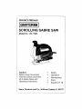
Owner's Manual
SCROLLING
SABRE SAW
Model No. 135.17243
Caution:
Before using this product,
read this manual and follow
all its Safety Rules and
Operating Instructions.
__
Safety
Operation
Maintenance
Parts
EspaSol, R 18
Sears, Roebuck and Co., Hoffman Estates, IL 60179
Page
Warranty .....................................................
Power Tool Safety Rules
Symbols
......................................
3-5
.....................................................
Functional Description and Specifications
Assembly
2
6
...........................
7
....................................................
Operating Instructions
........................................
Tool Tips .................................................
Maintenance
8
8-11
11-14
.................................................
15
Service Parts ..............................................
16-17
EspaSol ..................................................
18-32
FULL ONE YEAR WARRANTY
ON CRAFTSMAN
SCROLLING SABRE SAW
If this CRAFTSMAN Scrolling Sabre Saw fails to give complete satisfaction
within one year from the date of purchase, RETURN IT TO THE
NEAREST SEARS STORE IN THE UNITED STATES, and Sears will
replace it, free of charge.
If this CRAFTSMAN Scrolling Sabre Saw is used for commercial or rental
purposes, this warranty applies for only 90 days from the date of purchase.
This warranty gives you specific legal rights, and you may also have other
rights which vary from slate to state.
Sears, Roebuck and Co., Dept. 817WA, Hoffman Estates, IL 60179
-2-
Read and understand
all instructions.
Failure to follow all instructions
listed below, may result in electric shock, fire and/or serious personal injury.
SAVE
THESE
INSTRUCTIONS
Work Area
When operating a power tool outside, use
an outdoor extension cord marked "W-A"
or "W." These cords are rated for outdoor use
and reduce the risk of electric shock. Refer to
"Recommended sizes of Extension Cords" in
the Accessory section of this manual.
Keep your work area clean and well lit.
Cluttered benches and dark areas invite
accidents.
Do not operate power tools in explosive
atmospheres, such as in the presence of
flammable liquids, gases, or dust. Power
tools create sparks which may ignite the dust
or fumes.
Keep by-standers, children, and visitors
away while operating a power tool.
Distractions can cause you to lose control.
Personal
Safety
Stay alert, watch what you are doing and
use common sense when operating a
power tool. Do not use tool while tired or
under the influence of drugs, alcohol, or
medication.
A moment of inattention while
Electrical Safety
operating power tools may result in serious
personal injury.
Double Insulated tools are equipped with a
polarized plug (one blade is wider than the
other.) This plug will fit in a polarized outlet
only one way. If the plug does not fit fully
in the outlet, reverse the plug. If it still does
not fit, contact a qualified electrician to
install a polarized outlet. Do not change
the plug in any way. Double Insulation []
eliminates the need for the three wire
Dress properly.
Do not wear loose
clothing
or jewelry. Contain long hair. Keep your
hair, clothing, and gloves away from
moving parts. Loose clothes, jewelry, or long
hair can be caught in moving parts. Keep
handles dry, clean and free from oil and
grease.
Avoid accidental
starting. Be sure switch
is "OFF" before plugging in. Carrying tools
with your finger on the switch or plugging in
tools that have the switch "ON" invites
accidents.
grounded power cord and grounded power
supply system. Before plugging in the tool, be
certain the outlet voltage supplied is within the
voltage marked on the nameplate. Do not use
'_4C only" rated tools with a DC power supply,
Remove adjusting keys or wrenches
before
turning the tool "ON". A wrench or a key
that is left attached to a rotating part of the tool
may result in personal injury,
Avoid body contact with grounded
surfaces such as pipes, radiators,
ranges
and refrigerators.
There is an increased risk
of electric shock if your body is grounded.
If
operating the power too! in damp locations is
unavoidable, a Ground Fault Circuit Interrupter
must be used to supply the power to your tool.
Electrician's rubber gloves and footwear will
further enhance your personal safety.
Do not overreach.
Keep proper footing and
balance at all times. Proper footing and
balance enables better control of the tool in
unexpected
situations.
Use safety
equipment,
Always
wear eye
protection.
Dust mask, non-skid safety
shoes, hard hat, or hearing protection must be
used for appropriate conditions.
Don't expose power tools to rain or wet
conditions. Water entering a power tool will
increase the risk of electric shock.
Tool Use and Care
Use clamps or other practical way to
secure and support the workpiece to a
stable platform. Holding the work by hand or
against your body is unstable and may lead to
loss of control.
Do not abuse the cord. Never use the cord
to carry the tools or pull the plug from an
outlet. Keep cord away from heat, oil, sharp
edges or moving parts. Replace damaged
cords immediately. Damaged cords increase
the risk of electric shock.
-3-
Do not force
tool. Use the correct
tool for
caused by poorly maintained tools. Develop
a periodic maintenance schedule for your
tool,
your application. The correct tool will do the
job better and safer at the rate for which it is
designed.
Do not use tool if switch
"ON"
or "OFF".
Use only accessories that are
recommended by the manufacturer for
your model. Accessories that may be
suitable for one tool, may become hazardous
when used on another tool.
does not turn it
Any tool that cannot be
controlled with the switch is dangerous
must be repaired.
and
Disconnect the plug from the power
source before making any adjustments,
changing accessories,
or storing the tool.
Such preventive safety measures reduce the
risk of starting the tool accidentally.
Store idle tools
Service
Tool service must be performed only by
qualified repair personnel. Service or
maintenance
performed by unqualified
personnel could result in a risk of injury. For
example: internal wires may be misplaced or
pinched, safety guard return springs may be
improperly mounted.
out of reach of children
and other untrained persons, Tools are
dangerous in the hands of untrained users.
Maintain tools with care. Keep cutting
tools sharp and clean. Properly maintained
tools, with sharp cutting edges are less likely
to bind and are easier to control. Any
alteration or modification
is a misuse and
may result in a dangerous
When servicing a tool, use only identical
replacement
parts, Follow instructions
in
the Maintenance
section of this manual.
Use of unauthorized
parts or failure to follow
Maintenance
Instructions may create a risk
of electric shock or injury. Certain cleaning
agents such as gasoline, carbon
tetrachloride,
ammonia, etc. may damage
plastic parts.
condition.
Check for misalignment
or binding of
moving parts, breakage of parts, and any
other condition that may affect the tools
operation. If damaged,
serviced
before using.
have the tool
Many accidents
are
Hold tool by insulated gripping surfaces
when performing an operation where the
cutting tool may contact hidden wiring or
its own cord. Contact with a "live" wire will
first pulling the trigger then immediately
releasing it without pressing the "Lock-ON"
button,
Keep hands away from cutting area. Do
not reach under the material being cut.
make exposed metal parts of the tool "live"
and shock the operator.
Do not drill, fasten
or break into existing walls or other blind
areas where electrical wiring may exist. If
this situation is unavoidable,
disconnect all
fuses or circuit breakers feeding this
worksite.
The proximity of the blade to your hand is
hidden from your sight.
Keep hands from between the gear
housing and saw blade holder, The
reciprocating blade holder can pinch your
fingers.
Never leave the trigger locked "ON".
Before plugging
the tool in, check that the
trigger lock is "OFF".
Accidental start-ups
could cause injury.
Do not use dull or damaged blades.
Bent
blade can break easily or cause kickback.
Before starting to cut, turn tool "ON" and
allow the blade to come to full speed.
Tool can chatter or vibrate if blade speed is
too slow at beginning of cut and possibly
kickback.
Be aware of the location and setting of
the switch "Lock-ON"
button.
If the switch
is locked "ON" during the use, be ready for
emergency situations to switch it "OFF", by
-4-
Always wear safety goggles or eye
protection when using this tool. Use a
dust mask or respirator for applications
which generate dust.
_Some
created
by
power dust
sanding,
sawing,
grinding, drilling, and other construction
activities contains chemicals known to
cause cancer, birth defects or other
reproductive harm. Some examples of
these chemicals are:
Secure material before cutting.
Never
hold it in your hand or across legs. Small
or thin material may flex or vibrate with the
blade, causing loss of control.
• Lead from lead-based
• Arsenic and chromium
treated lumber.
from chemically-
Your risk from these exposures varies,
depending on how often you do this type of
work. To reduce your exposure to these
chemicals: work in a well ventilated area, and
When removing the blade from the tool
avoid contact with skin and use proper
protective gloves when grasping the
blade or accessory.
Accessories may be
hot after prolonged use.
Use only accessories
paints,
• Crystalline silica from bricks and cement
and other masonry products, and
Make certain all adjusting screws and the
blade holder are tight before making a
cut, Loose adjusting screws and holders
can cause the tool or blade to slip and lose of
control may result.
work with approved safety equipment, such
as those dust masks that are specially
designed to filter out microscopic
particles.
that are sold by
Sears for your model. Accessories that may
be suitable for one tool may become
hazardous when used on another tool.
-5-
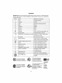
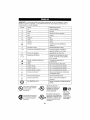
Symbols
IMPORTANT:
Some of the following symbols
and learn their meaning.
Proper interpretation
tool better and safer.
may be used on your tool. Please study them
of these symbols will allow you to operate the
Symbol
Name
Designation/Explanation
V
Volts
Voltage (potential)
A
Amperes
Current
Hz
Hertz
Frequency
W
Watt
Power
(cycles per second)
kg
Kilograms
Weight
rain
Minutes
Time
s
Seconds
Time
_l
Diameter
Size of drill bits, grinding
%
No load speed
.../min
Revolutions
Rotational
or reciprocation
per minute
Revolutions,
wheels,
etc.
speed, at no load
strokes, surface
speed,
orbits etc. per minute
0
1,2,3
....
Off position
Zero speed, zero torque...
Selector settings
Speed, torque or position settings.
I, It, III,
Higher number
Infinitely variable
-.€,
selector with off
Arrow
Alternating
I
Speed is increasing
from 0 setting
Action in the direction
current
of arrow
Type or a characteristic
of current
Direct current
Type or a characteristic
of current
Alternating
Type or a characteristic
of current
or direct current
[]
Class II construction
Designates Double Insulated
Construction tools.
@
Earthing terminal
Grounding
&
Warning symbol
Alerts user to warning
@
Ni-Cad RBRC seal
Designates
terminal
messages
Ni-Cad battery recycling
program
This symbol designates
lhat this tool is listed by
Underwriters Laboratories.
!_
means greater speed
0®
This symbol designates
that this tool is listed to
Canadian Slandards by
Underwriters Laboratories.
This symbol designates that
this tool is listed by
Underwriters Laboratories,
and listed to Canadian
that this tool is listed by
the
Standards
This Canadian
symbol designates
Association.
Standards by Underwriters
Laboratories.
-6-
This symbol
designates
that
this tool
complies
to NOM
Mexican
Standards.
F_i_I
Disconnect the plug from the power source before making any
assembly, adjustments or changing accessories. Such preventive safety
measures reduce the risk of starting the tool accidentally,
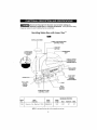
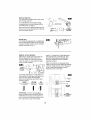
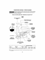
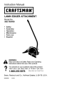
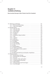
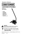
Scrolling
SCROLLING
Sabre Saw with Laser-Trac
KNOB
CONTROL
I
WHEEL
LASER LIGHT/WORKLIGHT
"LOCK-ON"
/_f--_-.
LASER LIGHT
ADJUSTMENT
SCREW
TM
BUTTON
RUBBERIZED
GRIP
/
VARIABLE SPEED
CONTROLLED
TRIGGER SWITCH
i
VENTILATION
OPENINGS
DUST PORT
/BLADE
STORAGE
COMPARTMENT
WORKLIGHT
TOOL-LESS
BLADE
CHANGE
COVER
FOOT
DUST
BLOWER
SWITCH
ORBIT/SCROLLING
CONTROL
LEVER
MAXIMUM CAPACITIES
Model
No,
Blade
Thickness
Blade
Action
Stroke
Length
Wood
Aluminum
Steel
17243
N1inmlum.7m111
- Maximum 1.7ram
Orbital/Scroll
13/16"
3-!/8"
1/2"
1/4"
NOTE:Fortool specifications refer to the nameplateon your tool.
-7=
+a_
i6!9X0<427
9-G4
9/23/04
9 ;04
_i,__ P
8
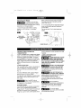
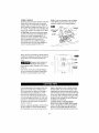
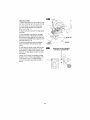
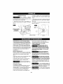
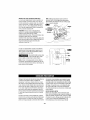
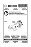
When inserting the saw blade, the back of
the blade must rest in the groove of the
guide roller (Fig, 3).
Attaching the Blade
To
prevent
personal plug
injury,
always
disconnect
from
power source before assembling parts, making
adjustments, or changing blades.
2. To remove blade, lift tool-less blade change
cover up with index finger and thumb and
remove blade.
1, Insert the saw blade (teeth in cutting
direction) until it latches in the plunger
(Fig. 2).
For use with both T or U shank sabre saw
blades.
f
...........................
BLADE---+
TOOL-LESS
COVER
GU DE ROLLER
VARIABLE SPEED CONTROLLED
TRIGGER SWITCH
Your tool is equipped with a variable speed trigger
switch, The tool can be turned 'rON" or "OFF" by
denser materials and faster speeds are for soft
materials.
LASER LIGHT/WORKLIGHT
CONTROL WHEEL
squeezing or releasing the trigger. The speed
can be adjusted from the minimum to maximum
_
ASER RADIATION,
AVOID
DIRECT
EYE EXPOSURE.
DO NOT stare into the laser light source.
Never aim light at another person or object
other than the workpiece.
Laser light can
damage your eyes.
nameplate SPM by the pressure you apply to the
trigger. Apply more pressure to increase the
speed and release pressure to decrease speed
(Fig. 1).
"LOCK-ON"
BUTTON
The "Lock-ON" button, located in the handle of
your tool allows Ior continuous operation at
maximum SPM without holding the trigger
DO NOT use tinted glasses
to enhance the laser light,
Tinted glasses will reduce overall vision for
the application and interfere with the normal
operation of the tool.
(Fig. 1).
TO LOCK TRIGGER "ON": squeeze
depress button and release trigger.
trigger,
_
Never aim the beam at a
workpiece
with a reflective
surface. Bright shiny reflective sheet steel or
similar reflective surfaces are not
recommended for laser use. Reflective
surfaces could direct the beam back toward
the operator,
TO UNLOCK THE TRIGGER: squeeze trigger
and release it without depressing the "LockON" button.
lf the "Lock-ON" button is
continuously being depressed,
the trigger can not be released.
PLUNGER
--
Use of controls or
adjustments or performance
of procedures other than those specified
herein may result in hazardous radiation
SPEED
The stroke rate may be adjusted as described
earlier under "Variable Speed Controlled
Trigger Switch". The best results for a particular
application are determined by experience,
though as a general rule, slower speeds are for
exposure.
will increase
-8-
÷
The use of optical
instruments with this product
eye hazards.
÷
SM !6i9X00427
9-04
9/23/04
9:04 AM
P_
9
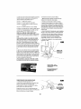
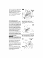
USING THE LASER
The 4 position control wheel allows you to
control the function of the lights. Below, lists
the function of each setting (Fig. 1).
LINE GUIDE
Onty turn on the laser light on when the tool is
on the workpiece.
Setting 1: Turns OFF all lights.
1. First mark the line of cut on your workpiece
(good side down.)
Setting 2: Turns ON only the laser light.
2. Insert plug into the power source.
Setting 3: Turns ON both the laser light and
the worklight.
3. Place the front edge of the saw foot on the
workpiece, turn the 4 position control wheel to
setting 2 for laser light only or setting 3 for
laser light and WORKLIGHT
and align beam
with the line of cut.
Setting 4: Turns ON only the worklight
The laser line guide is a class Ilia laser with a
maximum output power of 5.0m Watts and
conforms to 21 CFR 1040.10 and 1040.11.
4. Hold the tool firmly, squeeze the trigger and
allow the tool to reach desired speed.
LASER-TRAC TM LASER LINE GUIDE
The Laser-Trac line guide help you to follow
your cutting line with greater ease and
precision when making a cut.
5. Press down (to keep the saw foot flat
against the work surface) as you slowly push
the saw forward, keeping the beam in line with
the line of cut.
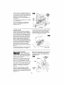
TO ADJUST THE LASER LINE GUIDE
Use a flat head screwdriver to turn the
adjustment screw located on the side of the
laser module (Fig. 4). Turn on the laser line
guide by rotating the control wheel to setting
number 2. Rotate the adjustment screw until
the laser line is in the center of the blade.
There is no need to turn the tool "ON" while
6. After completion of the cut, release
trigger and turn off the laser light.
the
adjusting the light beam.
The laser line guide has a limited amount of
travel. Do not continue to turn the adjustment
screw after the line stops moving or if it
becomes significantly harder to turn the screw.
Overturning the adjustment screw may cause
the adjustment system to break or cause the
adjustment screw to fall out of the tool.
I/
•AVOID EXPOSURE- LASER
RADIATION IS EMITTEO FROM
THIS APERTURE.
I
,,EVITE
LAEXPOSICII_N. DESDE I
ESTA ABERTU.RASEEMITE
RADIACIOH
LASER.
I
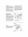
BLADE
STORAGE
COMPARTMENT
i"[i_1
Your sabre saw is equipped with a blade
storage compartment in the dust port of your
saw (Fig. 5). To remove, pull compartment
out of dust port in direction of arrow,
DUST
PORT
BLADE
Always make sure the bIade storage
compartment is securely in the dust port to
prevent blades from falling out.
COMPARTMENT
-9-
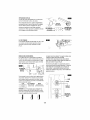
DUST EXTRACTION
Your sabre saw is equipped
dust and chip extraction,
with a dust port for
To use this feature, remove blade storage
compartment and move dust blower switch to
the "OFF" position "O" (Fig, 6).
Attach vacuum hose (optional accessory) to the
dust port, and connect opposite end of the hose
to a shop vacuum cleaner.
ON=o(
( I 1 3)1,-.--"-BLOWER
DUST
OFF=o(C ! 1:_"
SWITCH
WORKLIGHT
Your tool is also equipped with a worklight that
turns on automatically when the control wheel
is rotated to setting number 3 and 4, for better
visibility when cutting (Fig. 7).
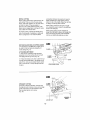
I_[dl M
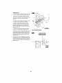
ORBITAL
position. To adjust foot, lift foot adjustment
lever and flip lever completely over, then
push foot forward as far as possible and
lower foot adjustment lever to maintain
adjustment (Fig. 9).
ACTION
MODELS
Orbital Action models have a lever (Fig. 8)
that will regulate the orbital action from
"Smooth" position for normal up and down
motion to maximum orbital action for faster
cutting in softer materials.
OrbitaI cut control is not observable
when
sabre saw is free running. Sabre saw must be
cutting for orbital action to occur. The speed
of cut is much more apparent in thicker
materials such as 2 by lumber.
To increase orbital action, turn the lever to a
higher setting. To decrease orbital action turn
lever to a lower setting. When minimal
splintering is desired we recommend using
"Smooth" position.
SMOOTH
LOW!MED
FAST
MILD STEEL/ SOFT METALS
METAL PLASTIC
SOFT WOODS
ALL MATERIALS
"lARD WOODS
PLYWOOD
ATTENTION:
I
ROLLER
GUIDE
In order to achieve orbital
FOOT
action, the blade must be facing STRAIGHT
FORWARD and the back of the blade must
rest in the groove of the guide roller, and the
foot must be all the way in the forward
tpJUSTMENT
LEVER
-10-
SCROLL
MODELS
Scrolling saws permit 360 ° rotation of the saw
blade without turning the saw, so intricate
designs may be cut with minimum effort. To
permit rotation of plunger turn lever, (Fig. 10)
to scrolling. The plunger of your scrolling saw
can also be locked in (4) positions, 90" apart.
Note: It may be necessary to turn scrolling
knob slightly back and forth to be sure the
plunger is locked in the desired position.
J
SCROLLING
KNOB
ATTENTION:
When scroll cutting the blade
must be moved away from the guide rollers
(aIways move foot completely back). To
adjust foot, lift foot adjustment lever and flip
lever completely over, then push foot
backwards as far as possible to engage
locking tab, then lower the foot adjustment
lever to maintain ac ustment (Fig. 11).
When manually scroll cutting, operate saw by
holding the handle with one hand and rotating
the scrolling knob manually with your free
hand.
_
broken blades
being cut.
\
©
xcessive side pressure to
the blade could result in
and/or damage
I_[liH
I'JC
I
to the material
ROLLER
GUIDE
Note: When scroll cutting intricate designs,
we recort/mend using a scroll cutting blade.
However, a standard blade can be used.
Face the good side of the material down and
secure it in a bench vise or clamp it down.
adjust or relocate the vise or clamps to keep
the work stable. Do not force the saw or the
Draw cutting lines or designs on the side of
the material facing up towards you. Then
place the front edge of the saw foot on the
work and line up the blade with the line to be
cut. Hold the sabre saw firmly, turn it on, and
press down (to keep the saw foot flat against
the work) as you slowly push the saw in the
direction of the cut.
blade teeth may rub and wear without cutting
and the blade may break. Let the saw do most
of the work. When following curves, cut slowly
so the blade can cut through cross grain. This
will give you an accurate cut and will prevent
the blade from wandering.
Build up cutting rate gradually, cutting close to
the line (unless you want to leave stock for
finish sanding). As you cut you may have to
CUTTING
WITH A STRAIGHTEDGE
Always use a rough cut blade when possible,
Clamp a straightedge on the work parallel to
the line of cut and flush with the side of the
saw foot, (Either first mark the line of cut and
-11-
then position the straightedge parallel and at
the same distance as between the blade and
the side edge of the foot or first mark the side
edge of the foot and then clamp the
straightedge on the mark and parallel to the
cut line Fig. 12).
On models with the scroll feature,
to lock scroller knob.
it is advised
As you cut, keep the saw foot edge flush
against the straightedge and fiat on the
workpiece (Fig. 12).
PLUNGE CUTTING
Plunge cutting is useful and time-saving in
making rough openings in softer materials. It
is not necessary to drill a hole for an inside or
pocket cut. Draw lines for the opening, hold
the saw firmly, tilt it forward so that the toe of
the saw foot rests on the work, but with the
blade well clear of the work. Start the motor,
and then very gradually lower the blade.
When it touches, continue pressing down on
the toe of the saw foot slowly pivoting the saw
like a hinge until the blade cuts through and
the foot rests flat on the work. Then saw
ahead on the line of cut line. We do not
recommend
(Fig. 13).
corner. After the opening is complete, go back
to each corner and cut it from the opposite
direction to square it off. Do not try to plunge
cut into hard materials such as steel.
J
plunge cutting with a scroll blade
To make sharp corners, cut up to the corner,
then back up slightly before rounding the
BEVEL OR ANGLE
CUTTING
To prevent damage to the
tool when bevel or angle
cutting, the scroll mechanism must be locked
in place with the cutting edge of the blade
facing the front of the tool.
Disconnect the cord from the power
The foot can be adjusted to cut any
lrom 0 ° to 45," and is equipped with
reference detent stops at 0 °, 15 °, 30
Note: If the foot becomes loose you can use a
screwdriver to tighten screw located on the
foot adjustment lever, then re-adjust the loot
adjustment lever.
FOOT
ADJUSTMENT
source.
angle
quick
°, and 45 °.
SCREW-_
TO ADJUST: Lift foot adjustment lever in the
bottom of foot as shown, move foot slightly
backward to disengage the locking tab
(Fig. 14).
Position foot to desired angle, then push
forward to engage locking tab and lower
adjustment lever to maintain adjustment. After
adjusting foot make a sample cut to check the
angle (Fig. 14).
TAB
-12-
LEVER
METAL CUTTING
When cutting metal clamp material down. Be
extra certain that you move the saw along
slowly. Use lower speeds. Do not twist, bend,
or force the blade. If the saw jumps or
bounces, use a blade with finer teeth, if the
blade seems clogged when cutting soft metal,
use a blade with coarser teeth.
For easier cutting, lubricate the blade with a
stick of cutting wax, if available, or cutting oil
when cutting steel. Thin metal should be
RIP FENCE
AND CIRCLE
CUTTING
When cutting aluminum extrusion or angle
iron, clamp the work in a bench vise and saw
close to the vise jaws.
When sawing tubing and the diameter is
larger than the blade is deep, cut through the
wail of the tubing and then insert the blade
into the cut rotating the tube as you saw.
GUIDE
This accessory is available at an extra cost. It
is used for fast and accurate straight and
circle cutting (Fig. 15).
ATTACHING
sandwiched between two pieces of wood or
tightly clamped on a single piece of wood
(wood on top of the metal). Draw the cut lines
or design on the top piece of wood.
CLAM p..--.---._
RIP FENCE
1. Insert bar of rip fence through the slots
SLOT
provided in foot, from either side of loot with
the edge guide facing down (Fig. 15).
2. Thread the clamp screw from
through the threaded hole in the
side of foot, and securely tighten
with a screwdriver, to clamp the
in place,
STRAIGHT
CLAMP
SCREW
under the foot
clamp on left
clamp screw
rip fence bar
CUTTING
Once the rip fence is attached, measure from
the edge of work to the line of cut, and set edge
guide of rip fence to the same distance and
then securely tighten clamp screw
(Fig. 16).
_
I
I
I
EDGE GUIDE DOWN
CLAMP ,
SCREW
, /_
DESIRED___
WIDTH
LINE OF CUT
-13-
CIRCLE
CUTTING
1. Before attaching the rip fence, draw a circle
and drive a finishing nail in the center of circle.
2. Drill or plunge cut near the circles edge,
turn saw off and disconnect the plug from
power source (Fig. 17).
3. Attach rip fence to saw with the edge guide
facing UP.
4. Place the metal center point on the edge
guide into the hole in the center of the circle.
In order for the edge guide to cut a circle, the
metal center point MUST BE in alignment with
saw blade (see Fig. 18).
(
\
5. Measure the distance from the selected
EDGE
GUIDE UP
hole to the bIade to be equal to the circle
radius.
6. Insert plug into power source, hold the saw
firmly, squeeze trigger and slowly push the
saw forward. To make a hole, cut from inside
J
"WEDGE
BLADE MUST BE IN ALIGNMENT
WITH METAL CENTER POINT
the circle; To make wheels or discs, cut from
the outside.
Cutting Tip: Cut slowly so the blade will stay
straight in the cut. Place small wedges in the
cut as shown in Fig. 17, to keep the inner
circle from spreading when near the end of
the cut.
-14-
Service
should be replaced at an Authorized Service
Center. Bearings which become noisy (due to
heavy load or very abrasive material cutting)
should be replaced at once to avoid
overheating or motor failure.
_
reventive
maintenance
performed by unauthorized personnel may result in misplacing
of internal wires and components which
could cause serious hazard. We
Cleaning
recommend that all tool service, including
service of laser, be performed by a Sears
Service Parts and Repair Center.
I__1
the power supply before cleaning or
performing any maintenance.
The tool may
be cleaned most effectively with compressed
dry air. Always wear safety goggles when
cleaning tools with compressed
air.
Tool Lubrication
Your tool has been properly lubricated and is
ready to use. It is recommended
that tools
with gears be regreased with a special gear
lubricant at every brush change.
Carbon
To avoid accidents always
disconnect
the tool from
Ventilation openings and switch levers must
be kept clean and free of foreign matter. Do
not attempt to clean by inserting pointed
objects through openings.
Brushes
The brushes and commutator in your toot have
been engineered for many hours of dependable
service. To maintain peak efficiency of the
motor, we recommend every two to six months
the brushes be examined. Only genuine Sears
replacement brushes specially designed for
your tool shouid be used.
_
ertain cleaning agents
and solvents damage
plastic parts. Some of these are: gasoline,
carbon tetrachloride,
chlorinated cleaning
solvents, ammonia and household
Bearings
After about 300-400 hours of operation, or at
every second brush change, the bearings
detergents
that contain
ammonia.
_lf
an is
extension
cord
is necessary,
a cord
with adequate
size
that
capable of
carrying
the current
necessary
for your
toolconductors
must be
used. This will prevent excessive voltage drop, loss of power or overheating. Grounded tools
must use 3-wire extension cords that have 3-prong plugs and receptacles.
RECOMMENDED SIZES OF EXTENSION CORDS
120 VOLT ALTERNATING CURRENT TOOLS
Tool's
Ampere
Rating
3-6
68
8-10
10-12
12-16
NOTE:
Cord Size in A.W.G.
Wire Sizes in mm2
Cord Length in Feel
Cord Length in Meters
25
50
100
150
15
30
60
120
18
18
18
16
14
16
16
16
16
12
16
14
14
14
14
12
12
!2
0.75
0.75
0.75
1.0
0,75
1,0
1.0
2.5
1.5
2.5
2.5
40
2.5
4.0
4.0
--
The smaller the gauge number, the heavier the cord.
-15-
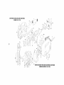
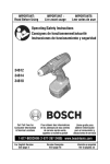
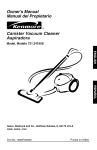
CRAFTSMANSCROLLINGSABRESAW MODEL
NUMBER135.17243
2
.810
13
/
14
19
I
850
28
65"
29
832
67
34
t
30
35
,=
42
75
70
71
61
74
SIERRADE VAIVE:NPARA HACERCONTORNOS
CRAFTSMAN
NUMERODE MODELO135.17243
KEY
NO.
PART
NO.
1
2
3
4
5
13
2610916229
2610913978
2610913979
2610924106
2610916910
2610967219
14
15
16
19
2610917489
2610018632
2610320548
2914201705
21
22
23
2610329898
2610968496
2610329896
28
29
30
34
35
2610914014
2610913999
2610914016
2610914010
2610914007
42
52
54
55
56
57
2610914011
2610914015
2610916883
2610914018
2610914884
2610913996
Bushing
Bushing
Spring Clip
Arm
Foot
Bracket
Roller
Pin
58
59
60
61
2610914020
2610914019
2610914022
2610913993
Spring Clip
Holder
Pin
Yoke
62
2610913994
Bolt
KEY
NO.
63
PART
NO.
2610913995
64
65
66
67
68
69
2610913992
2610917358
2610924134
2610916536
2610390329
2610912487
Lever
2
12
2
2
70
71
73
74
75
2610916094
2914201672
261O922316
2610924140
Lever
Screw
Lens
2
1
t
t
1
76
78
79
8O
81
1
1
1
1
1
1
84
85
86
87
88
810
1
2
1
1
826
832
836
1
1
PART NAME
Housing
Field
Armature
Switch
Cord
1
1
I
1
1
Bushing
Ball Bearing
Retaining Ring
Brush Holder
1
1
1
Screw
Spring
Cable
Terminal
Pusher
Clip
Counterweight
Shaft
2914201664
261O916537
2610018199
2918150120
2610916541
2610917102
2610922519
2610922520
2610923594
2610924145
2610924146
2610917266
2610917218
PART NAME
Nut
1
1
1
1
1
1
Locking Tang
Board Assembly
Lock Botton
Spring
Guard
1
1
1
1
1
3
1
Metal Front End
Screw
Lever
1
1
1
1
1
Spring
Set Screw
Blade Storage
Cap
Sled
Sled Holder
Cable Assembly
Cover
Insulation
Brush Set
844
261O917219
2610917220
2610917221
Bearing Plate Assembly
Gear Assembly
Plunger Assembly
Blade Holder Assembly
85O
2610917222
Knob Assembly
261O924135
Owner's
Manual
(not shown)
1
1
1
1
1
1
1
1
1
1
1
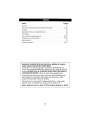
Indice
Pdgina
Garantia ....................................................
18
Normas de seguridad para herramientas
Simbolos
19-21
...................................................
Descripci6n funcional y especificaciones
Ensamblaje
mec_.nicas ...............
22
...........................
23
.................................................
Instrucciones de funcionamiento
..............................
24
24-27
Consejos para la herramienta .................................
Mantenimiento ...............................................
27-30
31
Piezas de repuesto .........................................
16-17
GARANTIA COMPLETA DE UN AI_IO DE LA SIERRA DE VAIVEN
PARA HACER CONTORNOS CRAFTSMAN
Siesta Sierra de Vaiven para hacer Contomos CRAFTSMAN no le
proporciona comp[eta satisfacci6n a partir de un afro desde la fecha de
compra, DEVUELVALA AL ALMACEN SEARS MAS CERCANO EN
LOS ESTADOS UNIDOS y Sears la reemplazara_gratuitamente.
Si esta Sierra de Vaiven para hacer Contornos CRAFTSMAN se usa
para propSsitos comerciales o de a[quiler, esta garantfa es valida
durante 90 dfas desde [a fecha de compra.
Esta garantfa le otorga derechos legales especfficos y usted puede,
adema.s, terler otros derechos que va6an de un estado a otro.
Soars, Roebuck
and Co., Dept. 817WA, Hoffman
-18-
Estates, IL 60179
Lea y entiendatodas las instrocciones.El incumplimiento de todas las instrucciones
indicadasa continuaoi6n puede dar lugar a sacudidaselectricas,incendios y/o ]esienes
personales graves.
CONSERVEESTASINSTRUCCIONES
Area de trahajo
Mantenga
el _readetrabajolimpiay hieniluminada.
Lasmesasdesordenadas
y las_reasoscurasinvitana
quaseproduzcan
accidentes.
No abuse del eord6n. Nunca use el eord6n para gevar
las herramientas ni para sacar el enchufe de un
tomaeorriente. Mantenga el cord6n alejadede! ealor, el
aceite, los bordesalilados o las piezas m6viles. Cambie
los cordones daRadosinmediatamente. Los cerdones
No utilice herramientasmecdnicas en almbsferas
daSadosaumentan el riesgo de qua se produzcan
sacudidas el_ctricas.
explesivas,tales come las existentesen presencia de
I[quidos, gaseso pelvesintlamables. Las
herramientas mecanicasgeneranchispas y _stas
puedendar lugar a la ignici6n del polvo o Insvapores.
AI utilizaruna herramlentamec_nica a la inlemperie,
utilJceuncordbnde extensi6npara intemperie
marcado "W-A" o "W". Estoseordones tienen
puedenhacer qua usted pierda el control.
capacidad nominaI para use a la intemperie y reducen el
fiesgo de qua se produzcaesacudidas eldctricas.
CensulLe"Tamales recomendados de loscordones de
extensi6n"en la seco!6nAccesorios de este manual,
Seguridadel_clrica
seguridadpersonal
Las herramientasconaislamiento doble est_n
Mant_ngasealerfa, fljese en Io queest_ hacienday
use el sentidocomz_ncuandoutilice unaherramienla
mec_nica. Nouse la herramienta cuandoest_
Mantengaa las personasquese encuentren
preseetes,a los nii'ios y a los visitantes alejados al
utilizar nnaherramientamecdnica. Las distracciones
eqaipadascon an enchufepolarizado (un terminal es
m_isancha que el otro). Esteenchufeentrar_ en un
tomacorrientepolarizadosolamentede una manera.
Si el enchufenoentra per complete en el
tomacorriente,d_le la vuelta. Si sigue sin entrar,
p6ngaseen contactoconun electricistacompetente
para instalar an tomacorrientepolarizado. No haga
ninglintipo de cambio en el enchufe.Elaislamiento
deble [] elimina la necesidadde] sisternade cerd6n de
energiade tres hiles conectado a tierra y la fuentede
energiaconectada a tierra. Antes de enchufar fa
herramienta, asegdlresede qua la tensidn dot
tomacnmente suministrada se encuentre dentro dot
margen de la tensJ6nespecilicadaen ta placa del
fabricante.No ufilice herranfientas con capacidad
nominal "ACsolamente" ('.4C oniy') con una fuentede
energiaDC
cansadoo se encuentrebajo la influenciade drogas,
alcoholo medicamenlos, Un memento de distraccion
al utilizar herramientas mec_nicas puededar lugar a
]esienespersonales graves.
Vistaseadecuadamente.No se ponga ropaholgada ni
joyas. Suj6teseel pelo. Mantengael pelo, la ropa y
los guantesalejadosde las plazasm6viles. La ropa
holgada,lasjoyas o el polo largo puedenquedar
atrapados en las piezas m6viles. Mantenga los mangos
secos, iimpios y libres de aceitey grasa.
Eviteel arranqae accidental.Aseg_resede que et
interrupterest_ en la posicibn"OFF" (apagado)antes
de enchufarla herramienta. E] Ilevar las herramientas
con el dedo en el interrupter o el enehufar herramientas
que tengan el interrupter en la posici6n "ON"
(encendido) invitaa qua se produzcanaocidentes.
Evite el contactodel cuerpoconlas superficies
conectadasa tierra tales come tuberfas, radiadores,
estafas de cocinay refrigeradores.Haymayer riesgo
de que se produzcansacudidaseleetricas si su cuerpo
esta conectado a tierra, Si la utilizaciM de ia
Quite las Ilaves de ajaste o de tuercaantes de
encenderla herramJenta,Una liars deaiuste o de
tuerca qua sedeje puesta en una piezagiratoria de la
herramientapuede oeasionarlesiones personales,
herramienta mecJnicaen lugares17_medoses
inevitable,se debe usar un interrupter de circuito para
ratiosa tierra para suministrar la energiaa la
herramienta. Los guantes de goma para electricista y el
_aizadoantideslizanteaumentaranm,_sla seguridad
personal
No inlentealcanzar demasiadolejos. Mantenga an
apoyo de los pies y on equilibria adecnadosen todo
memento. El apoyo de los pies y el equilibria
adecuadospermiten un major control de la herramienta
en situacienes inesperadas.
Noexpongalas herramientasmecanieasa la Iluvia ni
a situacionesh_medas. La entradade aguaen una
herramientamec_.nicaaumentarael riesgo de qua se
produzcansacudidas electricas.
Utilice equipo de seguridad. Use siempre protecci_n
de los ojos.Se debe eti[izaruna mascara antipolvo,
zapatosde seguridadantideslizantes, caseoo
protecci6n de los aides segL]nle requieran las
eondieiones.
-19-
Utilizaci6n y cuidado de las herramientas
Utilice abrazaderasn otrornodo pr;icticode lijar y
soportarla pieza de trabajoa una plataformaestable.
LasujecJ(Jnde la piezade trabajo con la mane o centre
el cuerpo resulta inestable y puedeocasionar p_rdida de
control
No fnerce la herramienta, Use la herramienta
correctapare la aplicaci6nque desea, La herramienta
correcta har_ el trabajo reelery con m_s seguridad ala
capacidadnominal pare laque est_ diseSada.
No utilice la herrarnientasi el interruptornola
enciendeo apaga. Toda herramientaque no se pueda
controlar con e] interrupter es peligrosay debe set
reparada.
Gearde las herrarnientasque noestd usandofnera
del aleance do los niiiosy otraspersonasno
capacitadas. Las herramientas son peligrosas en las
manes de los usuariosno capacitados.
Nlantenga las herrarnientasconcuidado.Conserve
Ins herrarnientasdocarte afiladas y lirnpias. Lax
herramientasmantenidas adecuadamente,con bordes
de corte afilados, tienen menos probabflidadesde
atascarsey son m_s f_ciles de controlar. Toda
alteraci6no modificacion constituye un use incorrecto y
puedetenor come resultado una situacion peligrosa.
Compruebe la desalieeacidno el atasco doIns piezas
mdviles, la rupturede piezasy cualquier olra
Nunca deje el gatille fije en la pesicidn"ON"
(encendido), Antesdo enchufarla herramienta,
cornpruebeque el cierre del gatillo est_ en la
posici(in "OFF" (apagado). Un arranque accidental
podria causer tesiones.
Utilice dnicamente accesoriosque est_n
recomendadospot el fabricantede su rnodelo. Los
accesorios que puedenser adecuados para una
herramientapuedenvolverse peligrosos cuando se
utiiizan en otra herramienta.
Servicio
Desconecteel enchnfede la fuente de energia antes
de hacercualquierajuste, carnbiaraccesorioso
guardarla herrarnienta.Estasmedidas de seguridad
preventivas reducenel riesgo de arrancar ]a herramienta
accidentalmente.
Sujete la herramienta por las superficies de agarre
aisladas cuando realice nnaoperacidn en la que la
berrarnienta de corfe pueda entrar on contactocon
cables ocnltos o consu propiocord(_n. El contacto
con un cable que tonga corriente har(i que _sta pase a
las partes metalicas descubiertas de la herrarnienta y
que el operador reciba sacudidas eldctricas. No
taladre,romp& ni haga trabalo de sujeci6n en
paredes existeetes ni en otras areas ciegas donde
pueda haber cables el_ctricos. Siesta situaci6n es
inevitable, desconecte todos los fl]sibtes o
cortacflcuitos que alimentan este sitio de trabajo.
sitnacidnque puedaafectar el funcionarniento de las
herramientas.Si la herrarnlentaesl(i daflada, haga
que realicenun serviciode ajustesy reparacionesa
la herrarnientaantes de nsarla. Muchosaccidentes
son causados per herramientasmantenidas
deficientemente.Establezcaun prograrnade
mantenimiento peri6dicc pare la herramienIa.
Elserviciode ajustesy reparacionesdo una
herrarnientadebeser realizado _nicamente par
personaldoreparacionescornpetente.El servicio o
mantenimiento realizadoper personal no competente
podria ocasionarun peligro de que se produzcan
lesiones. Per ejemplo: Los cables internes pue(fen
colocarse real o pellizcarse,Ins resertes de retorno de
les.protectores de seguridad puedenrnontarse
inadecuadamente.
A[ realizerserviciode ajuslesy reparacionesde una
herramienta, utilice _nicarnente piezasde repuesto
id_nticas.Sioa las instrnccionesque aparecenen la
secci6nMantenirnientodoeste manual, El use de
piezas no autorizadas o elincumpiimiento de las
instrucciones de Mantenimiento puedeocasionar un
peligro de que se produzcansacudidas el_ctricaso
lesiones. Ciertos agentesde limpieza,tales come
gasolina, tetracloruro de carbeno, amoniaco, etc.,
puedendaSarias piezasde pl_stico.
Sepa la nbicaci6n y la posici6ndel bet(in de
"Fijaci(Sn on ON" del interrupter. Si el interruptor
esta file en la posici6n "ON"durante el use, este
preparado para en situaciones de ernergencia ponerlo
en "OFF",tirando primero del gatillo y solt_ndolo
inmediatamente despuessin oprimir el botdn de
"Fijaci6n en ON".
Mantenga las manes alejadas del (irea do corle.
No ponga la rnano debajo del material quese est(i
cortando. La proximidad de la hoja ala mane queda
oculta a ia vista.
Mantengalasmanesalejadasdelespacioentrela
cajadoengranajes
y el soportedela holede
sierra. EIsoportedela hojadevaiv_npuede
peHizcarle
los dedes.
Nontilicehojasdesliladasni dafladas. Unahoja
dobladapuederompersefaciimenteo causer
retroceso.
-20-
Antesdecnmenzaret cnrte,enciendala
herramientay dejeque lahnjaalcancetndasu
velncidad.Laherramientapuedechirriaro vibrarsi
lavelocidadde lahnjaesdemasiadolentaal
cnmienzodelcortey posiblementepuede
experimentarretrocese.
Use s61nIns accesnrinsvendidnspnr Sears para su
modeln. Los accesoriosque puedenser adecuadns
para una I_erramienta,puedenser peligrosos si se
utilizan en otra herramienta.
Usesiempregalasdeseguridadn protecci6ndeIns
njns cuandnatiliceestaherramienta.Useuna
mascaraantipnlvoo unrespiradnr
para
aplicacinnes
quegeneranpolvn.
Fijeel materialantesde¢ortar. NuncaIn lengaen
la mannni snbrelaspiernas.Ei materialpequeSoo
delgadopuedecurvarseo vibrarcon lahnja,
causandoperdidade control.
Aseg_resede quetodnsInstnrnillnsde ajusle y el
sopnrtedela hnjaestenapretadns
antesdehacer
ancorte. Si instornillnsde ajustey Inssoportes
est;_nflojos, puedenhacerquela herramientan la
hojaresbale,pudiendoproducirsep_rdidadecontrol,
AI quitar la hojadela herramienta,
eviteel
contactoconla plelyusegnantesprnlectnres
adecuadns
al agarrarla hojan el accesnrin.Los
accesnrinspuedenestarcaiientesdespu6sdel uso
prolongado
-21-
Ciertn pnlvogeneradnpnr el
lijadn, aserradn,amnlado y
laladrado mec_nieos, y pnr ntras actividadesde
cnnstrucci6n,cnntieneagentesquimicnsqnese sabe
que causanc_ncer, defectnsde nacimientou otrns
dafiossnbre la reprodocci6n.Algunns ejemplos de
eslos agentesquimicnsson:
• Plomo de pinturas a basede plomo,
• Sflicecristalina de ladrillos y cemento y otrns
productns de mampostefia, y
• Ars_nicn y cromo de maderatratada quimicamente.
Su riesgo pnr causade estasexposiciones varfa,
dependiendode con cu&ntafrecuencia reatice este tipo
de trabajo. Parareducir suexpnsici6n a estos agentes
quimicos: trabaje en un ;_reabien ventilada y trabaje con
equipo de seguridad aprnbado,como pot ejemplo
mascarasantipolvo que esten dise_adasespecialmente
para impedir mediante filtracion el paso de partfculas
microsc6picas.
tMPORTANTE: Es posible que algunos de los sfmbolos siguientes se usen en su herramienta. Por favor,
estedielos y aprenda su significado, La interpretaei6n adeeuada de estos simbolos Is permitira utilizar la
herramienta meier y con m;_sseguridad.
Simbo!o
Nombre
Designaci6nlexpiicaci6 n
V
Vnlt
Tensi6n (potencial)
A
Ampere
Corriente
Hz
Hertz
Frecuencia(ciclos per segundo)
W
Watt
Potencia
kg
Kitogramo
Peso
rain
Minute
Tiempo
Segundo
Tiempo
Diametro
Tamafio de las brocas taladradoras,
muelas, etc
Velocidad sin carga
Velocidad rotacional sin carga
Revoluciones o alternacion per minute
Revoluciones, golpes, velocidad de
supedicie, 6rbitas, etc., per minute
Posici6n "off" (apagado)
Velocidad eero, par motor cero...
Graduaciones del selector
Graduaciones de velocidad, par motor o
position. Un n_mero m_s alto significa
mayor velocidad
Selector infinitamente variable con
La velocidad aumenta desde la
apagado
graduaci6n de 0
""_
Flecha
Acci6n en la direeci6n de la flecha
"_\/
Corriente alterna
Tipo o una caracteristica de corriente
Corriente continua
Tipo o una caracteristica de corrienle
Corriente alterna o continua
Tipo o una caracteristica de corriente
[]
Construcci6n de clase I!
Designa las herramientas de construction
con aislamiento doble.
0
Terminal de toma de tierra
Terminal de conexi6n a tierra
t_
Simbolo de adverteneia
Ateda al usuario sobre mensajes de
advertencia
Sello RBRCTM de Ni-Cd
Designa el programa de reciclaje de baterias
de Ni-Cd
s
0
nO
...imin
0
1.2 3....
I, II, III,
o.,.dl
_
herramienta esta catalogada
Esle simbolo indica que esta
per
Underwriters
Laboratories.
herramienta esta catalogada
Estelasimbolo
par
Canadian
indiea
S_andards
que esta
Association.
C
Estesimbolo indica que
Underwriters Laboratories ha
catalogado esta berramienta
indicando que cumple las
norrnas canadienses.
Q
j_,
I' | |l
C _Vll
_
JU_
-22-
Este simbolo indica que esta
herramienta est,1eatalogada per
Underwriters Laboratories y que
Underwriters Laboratories la ha
catalogado segun las normas
eanadienses.
Este simbolo
indica que esta
herramienta
cumple con la
norma mexicana
oficial (NOM).
DESCRIPCI6N FUNCIONAL Y ESPECIFICACIONES
_
esconecte el enchufe de la luente de energia anles de realizar cualquier ensamblaje
o ajuste, o cambiar accesorios. Estasmedidas de segufidad preventivas reducen el
riesgo de arrancar ia herramienta accidentalmente.
Sierra de vaiv_n para hacer contornos con Laser-TracTM
ll[_il
POM0DEOESPLAZAMIENTO
CONTINUO
BUEOADECONTROL
DELALUZ
L/_SER
Y LALUZOETRABAJO
BOTONDE
"FIJACIONENON"
/_'_,
TORNILLODE
EMPU_ADURA
AJUSTEDELA
LUZLASER
,-L
CAUCHUTAOA
INTERROPTOR
(DEENCENDIDO
Y
APAGADO)
ABERTURAS
DE
--VENTILACION
0RIFICIOPARA
POLVO/
COMPARTiMIENTO
PARAGUARDAR
HOJAS
LUZDETRABAJO-/i
CUBIERTA DE
CAMBI0 DE HOJA
SIN HERRAMtENTAS
BASE
--DEL
INTERRUPTOR
SOPLADOR
DEPOLVO
PALAXCADECONTROL
_RBITAL/DESPLAZAMIENTO
CONTINUO
No. de
modelo
Espesorde
la hoja
Accionde
a hoja
17243
Miriirno .7mm- M_,ximo1,Tram
Orb./Desp. cont.
CAPACIDADESMAXIMAS
Long. de
carrera
Madera Aluminio
Acero
20 mm
6 mm
80 turn
12 mm
NOTA: Paraobtener las especificacionesde la herramienta, consulte la placa de] fabricantecolocada en
la herramienta.
-23-
Colocaci6n de la hoja
_
Para
prevenir
lesiones
personales, desconecte siempre
el enchufe de la fuente de eoergia antes de montar
piezas, realizarajustes o cambiar hojas.
1. Introduzca la hoia de sierra (con Ins dientes en el
sentido de corte) hasta que se acople en el embele
(Fig 2).
AI introducir la hoja de sierra, la parte posterior de la
hoja debe descansar en la ranura del rodilio de gufa
(Fig. 3).
2. Para quitar la hoja, levante la cubierta de cambio de
hoja sin herramientas con Ins dedos indice y pulgar y
quite la hoja.
Para utilizarse con hejas de sierra caladoracon cuerpo
tanto en T como en U.
HOJA
UBIERTADECAMBIO
DEHOJASIN
HERRAMIENTAS
, gas1
RODILLODEGuJA--
INTERRUPTORGATILLODEVELOCIDADVARIABLE
La herramientaest,, equipadacon un inlerruptor gatfllo
de velocidadvariable.La herramientase puedeeneender
(posici6n "ON')o apagar(posici6n "OFF')apretandoe
sottando el gatillo. Lavelocidadse puedeajustar desde
las CPM minimas hasta las CPMm_ximas indicadasen
ta placadel fabbcante por medio de la presi6n que usted
ejerce sobreel gatillo. Eierzam_s presion para aumentar
ta veIocidady disminuya ta presi6n para reducir la
velocidad (Fig.1).
BOTONDE"FIJACIONEN ON"
El bot6n de"Fijaci6nen ON".ubicado enel mangode la
herramienta, permiteun funcionamientocontinuo a CPM
m_ximas sin tenor que mantenerapretadoel gatillo
(Fig.1).
PARAFIJARELGATILLOENLA POStCION"ON":apriete
eJgatillo, optima el bot6ny suelteel gatillo.
PARADESBLOQUEAR
EL GATILLO:aprieteel gaIiltoy
su_ite]osin oprimir el bot6nde "Fijacionen ON"
Si
seoprime
continuamenteel
bot6n
de "Fijacion
en ON", no se
,JtUIL J
bajas son para materiales mas densos y las
velocidades m_s altas son para materiales blandos.
RUEDADE CONTROLDE LALUZ L_,SER
Y LALUZ DETRABAJO
_
RADIACION
LASER.EVITELA
EXPOSICI(]NDIRECTADELOS
OJOS.No mire a la fuente de luz Idser. No apunte
nuncala luz hasia otra personao hacia otroobjeto
queno sea la piezade trabajo. La luz I_serpuede
da_ar ins ojos.
No
use lentes tintadospare
inlensificarla
luz laser. Los
lentes tintados reduciran la visi6n total para realizar ta
aplicaci6n e interferiran con el funeinnamiento normal
de la herramienta.
No
el rayo
hacla
unaapantenunca
pieza de trabajo
quelenga
ariasuperficie reflectora, La chapa de acorn reflectora
brillante y resplandecienleo las superficies reflectoras
similares no se recomiendan para usar un 19ser.Las
superficies refleetoras podrian dirigir el rayo de vuelta
hacia el operador.
puedesoltar elgatil]o.
VELOCIDABDEL EIVIBOLO
La velocidad de carrera puede aiustarse tal como se
describio anleriormente en "lnterruptor gatillo de
velocidadvariable". La seieccion de la posici6n optima
a fin de obtener Ins meiores resultados para una
aplicaci6n especiflca se basa en la experiencia,
aunque como norma general, las velocidades mas
Ei
uso de eontroles
o ajustes, o
la
realizacionde
proeedimientos
que
no sean Ins que se especifican en este manual, podria
causar una exposici6n peligrosa a la radiaci6n.
Ei uso de instrumentos 6prices
con este producto aumentara Ins
peligros para ins ojos.
-24-
La rueda de control de 4 posiciones permite al operador
controlar la funci6n de los luces. A continuaci6n se
indica la funci6n de cada posisi6n (Fig, 1).
herramienta este sobre lapieza de trabajo.
1, Marque primers lalinea de code en la piezade
trabajo (con el lads bueno hacia abajo)+
Posici6n 1: Apaga todas las luces.
Posicion 2: Enciendesolamente la tuz I_ser,
2. Introduzca el eochule en la fuente de energia.
3, Cdoque el borde delantero de la base de la sierra
sobre la pieza de trabajo, gire larueda de control de 4
posiciones hasta la posici6n 2 para seleccionar la tuz
l_ser solamente ohasta laposici6n 3 para seleccionar
la luz I;_sery ta luz de trabajo, y alineeel rays con la
ifnea de code.
Posici6n 3: Enciendetanto ia luz I;_sercome la luz
Site-Ligth,
Posici6n 4: Enciendesdamente ta luz de trabajo.
La guia de la finea del I;_seres un laser de claseIliA con
una potencia de salida m_iximade 5.0 mW y cumpie
con las normas 21 CFR1040.10 y 1040.11.
4. Sujete firmemente la herramienta, apriete el gatillo y
deje que la herramierltaalcance la veiocidad deseada.
GUiADE LALiNEADELLASERLASER-TRAC
TM
La guia de ia IfneaLaser-Tracle ayuda a seguir la linea
de eorte con mayor facilidad y precisi6n al realizar un
code,
PAFIAAJUSTARLAGUIADELALiNEADEL LASEI_
Utilice un destomillador de sabezaplana para girar el
tomillo de ajuste ubicado en el lads del m6dulo del
laser (Fig. 4). Enciendala guia de ia I[neadel I&ser
girando la rueda de control hasta la posici6o nQmero 2,
Gire el tornillo de ajuste ,haslaque la Ifnea delI_.serest_
en el centre de la hoja, No hay necesidadde encender
la herramientamientras se este ajustando el rays de
luz.
5. Presionehacia abajo (paramantener la base de la
sierra piano contra lasuperficie de trabajo) a medida
que empuja lentamentela sierra hacia delante,
manteniendod rays en Ifneacon la Ifneade code.
6, Despues de completar el corte suelte el gatillo y
apague la luz I_ser,
li[_ _]
La guia de la If_leadel laser tiene una cantidad limitada
de recorrido, No contim]e girando e{ tornillo de aluste
despues de que la Ifneadeje de moverse o si Ilega a set
signiticativamente mas diffcil girar el tornillo, Si se gira
excesivanrenteel tornilto de ajuste, el resultado podrfa
ser que el sistema de ajuste se rompa o qne el tornilin
de ajuste se caigade la herramienta.
UTILIZACI(}NDELA GUiADE LALiNEADELLASER
TORNILLODE
AJUSTEDELA
LUZLASER
Enciendagu2ade la linea del I_sersolamente cuando ia
• A_OIDEXPOSURE-LASER
RADIATIONIS EMITTEO FROM
THIS APEeTURE.
• EVITE LA EXPOSICIONr DESDE
ESTA ABEFITU_ASE EMIle
RADIACION LASER.
COMPARTIMIENT0PARAGUARDARHOJAS
La sierra de vaiv6n esta equipadacon un
compartimiento para guardar hojas en el orilicio para
polvo de lasierra (Fig, 5). Para quJtardiche
compartimiento, tire de 61en et sentido de laflecha
Ilasta separarlo del orilicio para polvo.
ORIFICIO
PARAPOLVO
Aseguresesiempre de que el compartimiento para
guardar hojas este firmemente sujeto en el orificio para
polvo para evitar que/as hojas se caigan.
-25-
HOJAS
EXTRACCIONDEPOLVO
La sierrade vaiv_n est_ equipadacon un orificio para
polvo a fin de extraerel polvo y lasvirutas.
Parautilizar este dispositivo, quite ei eompartimiento
paraguardar hojasy muevael interruptor del soplador
de polvo hasta la posici6n de apagado"0" (Fig, 6).
PARAPOLVO
INTERRUPTOR
Coloqueuna manguerade aspiraci6n(accesorio
opcionai) en el orificio para polvo y conecteel otro lado
de ia mangueraa unaaspiradora de taller.
ENCENDIDO=o(
_ _DELSOPLAOOR
APAGADO--.o_-I--F
_ )l
DEPOLVO
LUZ DE TRABAJO
La herramientatambi_n est;i equipadacon una luz que
se eociendeautoroaticamentecuando se activa el
interruptor, para tener mejor visibiiidad al cortar
(Fig. 7).
IIIPlll
MODELOSDEACCI(]NORBITAL
completamentebaciadelante. Paraajustar la base, suba
ta palancade ajuste de la base,basclJlela
completamente,luego empuje la base haciadelante
tanto como sea posible y bale lapalancade ajuste de la
base para mantenerelajuste (Fig. 9).
Los modelos de acci6n orbital tienen una palanca
(Fig. 8) que regula ia acci6n orbital desde la posicf6n
'suave' para movimiento normal hacia arriba y hacia
abajo hasta la acci6n orbital m_xima para corte m_s
r_pido en materiales mas blandos.
El control de corte orbital no es observablecuando la
sierrade vaiven esta funcionado libremente. La sierra de
vaiv6n debeestar cortando para que se produzcala
acci6n orbital. La vetocidadde cortees mucho mAs
evidenteee materialesmas gruesos,como maderade 2
pulgadasde grosor.
I_[_!_]
PALANCP
CONTROL
ORBITAL
Para aumentar la acci6r] orbital, gire la palanca hasta
una posici6n mJ.salta. Para reducir la accic_norbital,
gire la palanca hasta una pesici6n mas baja. Cuando
se desee que el astiliado sea minimo, recomeodamos
utilizar ia posiciOn "suave".
SUAVE
BAJA/IHTERMEDIA RAPIDA
ACE_O SUAVE _ METAL__S
MET&L PLASTICO
MAOERAS BLANDAS
BL ANDOS
MADERAS DURAS
MADERA CONTRACHAPADA
TODOS LOS MAT_ Rill
"._,,._ _/_I;._,_.-,,_•
_\
!--BASE
i ,,I A
i RODILLO
DEGU]A
ES
ATENCI()N:Conel fin de Iograr acci6n orbital, la hoia
debe estarobentada RECTAHACIADELANTE,la parte
trasera de la hoja debedescansaren la ranura del rodiNo
de guia y la base debeestaren iaposici6n
-26-
i t,..J
PALANCADE
MODELOS DE DESPLAZAMIENTO CONTINUO
Las sierras de desplazamientocontinue permiten una
rotaciCnde 360° de la hoja de sierraa fin de que los
dise_os complicados se puedancortar con un esfuerzo
minima. Parapermitir la rotaciCndeJ_mbolo, gire ta
palanca,(Fig. 10), a fin de desplazamiento.El _mbolo
de la sierra de desplazamientocontinue se puedelijar
en (4) posiciones separadas90°.
Nota: Puede que sea necesariogirar el paine de
desplazamientocontinue ligeramente haciaarras y
hacia adelantepara asegurarsede que el 6mbolo est;_
fijo en laposicion deseada.
POMODE
J
_
DESPLAZAMIENTO/
ATENCION:AI I]acer cortes de despiazamiento
continue, la hoja debemoverse alej#,ndosede los
rodillos de guia. (Mueva siempre la base
completamente haeia atr_ts.)Paraajustar la base, suba
ta palancade ajuste de la base, basct_lela
completamente, luego empuje ia base haciaatRis tanto
come sea posible paraacopiar la lengiJetade fijaniCny
iuego baje la palancade aluste de la base para
mantener el ajuste (Fig. 11).
CONTINUO
I
_j
_
v'__
PALANCA'--'-_
] ]1
A] coriar con desplazamientecontinue manualmente.
hagafuncionar la sierra agarrando el mango con una
maney girando et paine de desptazamientocontinue
rnanualmentecon fa mane libre.
Y_X.____
_'_ _-__
f
li_,
1
HOJA
Una presiCn lateral excesivasabre
la hola podrfa dar lugar a holas
rotas y/o dagos al material que se est_icortando.
Nota: AI eortar con despiazamientocontinue disefios
complicados, recomendamos la utilizaciCnde una hoja
de carte para despiazamientocontinue. Sin embargo, se
puede utilizar una hoja est_ndar.
Coloque et ]adobuenadel materialhaciaabajo y fijelo en
un tornillo de earpinterode banco o sujetelocon
abrazaderas.Tracelineas o dise_os de carte en el lade
del material que esta orienlado haciaarriba, hacia usted.
Lueg& coloqaeel horde delanterode la basede la sierra
sabre la piezade trabatey alinee lahoja con la linea que
seva a cortar. Agarre lasierrafirmemente, enci_ndalay
ejerzapresi6n haciaabajo (paramantenerla base de fa
sierra en posicion horizontaltocando la piezade trabajo)
a medida que empuia lentamentelasierra en el sentido
de code.
Aumente lavelocidadde carte gradualmente,cortando
cerca de la lfnea (a menos que quieradejar material para
tijadode acabado).A rnedidaque usted vayacortan(lo,
puedeque tongaque ajustar o cambiar de sitio el tornillo
de carpintero olas abrazaderaspara manlener la pieza
de trabajoestabie.No fuerce la sierra,si no los dientes
de la hoja puedenrozar y desgastarsesin cedar y la hoja
se puederomper, Dejeque la sierra hagala mayor parle
deItrabafo, AI seguir las cui_as, corie lentamente para
que la hoja puedacedar en direcei6ntransversal a la
vet& Estoproporcionara un carte precise y evitar;_que la
sierrase desvie.
CORTECONREGLARECTA
Siempre que sea posible, utilice una hoja de carte
bast& Fijecon abrazaderassabre la piezade trabajouna
reglarecta paralelaa la lineade carte y parejacon el lade
de la basede la sierra. (Marque primero lalinea de eerie
y luego eoiaque la reglarectaparalelamentey a ia
rnisma distaaciaque existe entre la heray el borde
-27-
lateral de la base o marqueprimero el horde lateral de la
base y luego fiie con abrazaderasla reglarecta sobre esa
marca y paralelamentea la lineade corte (Fig. 12).
En los modelos con el dispositivo de desplazamiento
continuo, se recomienda bloquear el pomo de
desplazamiento continuo.
Cuandc corte, mantengael borde de la base de la sierra
parejocon la regta rectay apoyado horizontalmente
sobre la piezade trabajo (Fig. 12),
CORTEMEDIANTEDESCENSOVERTICAL
El corte mediante deseensovertical es titil y ahorra
[iempo at hacer abeduras bastas en materiales mas
blandos. No esnecesario_acerun agujero para un corte
interioro de bolsillo.Trace ffneaspara laabedur& agarre
Issierra tirmemente e inclinela hacia adelanteparaque la
punla de la base de lasierra estd apoyadasobre la pieza
de trabajo, pero con la hoja bien alejadade la piezade
lrabajo. Ar[anque el molor y luego baje la hoia muy
graduaimente.Cuandohagacontacto,continOeejerciendo presi6n haeiaabajo sobre la puntade la basede Ia
sterra, baciendopivotar la sierralentamentecomo una
bisagra ilasta que la hoja cortey la base seapoye horizontalmentesebre la piezade trabajo.Luego,aserre
hacia adelantesiguiendo la linea decode. No
recomendamos el corte mediantedescensovedical con
esquina.Despu_sde terminar taabedura, vuelva a cada
esquinay cSrteladesde elsentido contrario para
completar eianguio recto. No intente cortar mediante
descenso vertical en materiales duros como pot
ejemplo acero.
una hoja paradesplazamientocontinuo (Fig, 13).
Parahaceresquinas muy pronunciadas,corte hasta ]a
esquinay luego retrocedafigeramenteantes derodear la
CORTEINCLINADOOEN ANGULO
_Para
evitar dafios a la herramienta
al realizarcodes inclinados o en
_,ngu]o,et nrecanismo de desplazamientocontiouo debe
estarlijo en su posicion con el borde de corte de Iahoja
orientado haciala partedelantera de ia herramienta
Nota: Si la baseseafloja, sepuedeusar un destorniliador
para apretarel tomi!lo ubicado en iapalancade ajuste de
la basey tuegoreajustarla palancade ajustede la base.
PALANCADEAJUSTE
DELABASE
Desconecteelcord{_nde la luentede energia. La base
puedeajustarseparacortar cualquier&ngulodesde 0°
basra45° y est,_equipadacon topes de retch de
referenciarapidaa 0°, 15°, 30° y 45°.
I
PARAREALIZARELAJUSTE:Suba lapalancade aiuste
de la baseque esta en la parteinlerior de dicha base de la
maneraque semuestra en la iluslracibn y mueva labase
ligeramentehaciaarrasparadesacoplar la lengQetade
fijacion (Fig. 14).
Posicionelabase en elangulo deseado,luego empuje
LENGIJETA
DE FIJACli)N
haeiaadelanteparaacoplar la leng[ietade fijacion y baje
la palancade aiustepapamantenerelajuste. Despuesde
aiustar labase, hagaun ccrte de muestra para
comprobarel angulo (Fig. 14).
-28-
CORTEDEMETAL
tuedemente con abrazaderasa una sola piezade madera
(la maderasobre el metal).Trace las lineas o el dise5o
de code sobre ]a piezasuperior de madera.
AI cortar metal,fJjeei materialcen abrazaderas.
AsegOresemuy bien de que haceavanzarla sierra
lenlamenle. Utiliee velocidades m_s bajas. No tuerza,
doble, ni luerce la hoja. Si lasierra saltao rebota, utilice
una hoia con dientesmas fines. Si pareceque la hoja se
atascaal cortar metal blando, utilice unaheja con
dientesm_s gruesos.
AI cortar aluminio extrudado o hierro angular, fije la
piezade trabajo en un torniilo de carpintero de banco y
aserrecerca de ias mordazasdel tornillo de earpintero.
Cuandoseaserrantubes y el di_.metroes mayor que la
profundidad hasta la cual ]a _oia puede penetrar,eorte
atravesandola pared de los tubes y luego introduzca la
hoja en el corte girando eitube a medidaque va
aserrando.
Paracortar con m_s facilidad,lubrique la hoja con una
barrade cerade code,si esta disponible, o con
querosenocuando secoda aluminio o conaceite de
cortecuando se eortaaeero. El metal delgado se debe
colocar entre dos piezasde madera o se debefijar
TOPE-GUIAPARACORTARAL HILO
Y GUIADECORTECIRCULAR
Esteaccesorio se encuentradisponiblea un costo
adicionaLSe utiliza paracodes rectoy circular r_pidos y
precisos (Fig. 15).
COLOCACION
DELTOPE-GUIAPARACORTARAL HItO
ASRAZADERA
1. ]ntroduzcala barradeltope-guiaparacortar al hilo a
tray, s de las ranurasde queest_ dotadala basedesde
cualquierade los dos lades de labase con la guia de
borde orientada haciaABAJO(Fig. 15).
TORNILLO
--'
RANURA
DE--_
FIJACION
2. Enrosque el torni!lo de fijaci6n desde debajo de la
base en el aguiero roscado de Ia abrazadera que esta
en el lade izquierdo de la base y apriete lirmemente el
tomillo de fijaci6n cen un destorniliador para fijar en
su sitie la barra del tope-gufa para cortar aFhilo.
GUIADEBORDE
HACIAABAJO
TORNILLO
DE
FIJACION
CORTERECTO
Unavez que se hayacolocado el tope-guia para cedar al
bile, mida desdeel bordede Ispieza detrabajo basrala
lineade co[re, coloque laguia de be[de del tope-guia
para cortar al bile a la misma distanciay apriete
firmemente eltornillo de fijacion (Fig. 16).
ANCHO
DESEADO
LINEADECORTE
-29-
CORTECIRCULAR
1[ef il'J
1. Antesde coIocar eltope-gu[a para cor_aral hiIo, trace
un drculo y claveun clavofino en el centrodet circuIo.
2. Per[ore un corte o realicelo mediante descenso
vedical cerca del borde de] circulo, apague la sierra y
deaconecfe el enchufe de la fuente de energia
(Fig. 17).
3. Coloque el tope-guia para cortar al hilo en la sierra
con la gu[a de borde orientada hacia ARRIBA.
CUbA
4. Ponga la punta central del metal,on la gu[a de
borde, en e! orificioen el eentro del cireulo. Afin de
quela guia de borde corte un c[rculo, elpunto de
centro de metal D EBEestar alineado con la hoja de
lasierra (ver Fig. 18),
/
\
\\
5. Mida la distancia desde el agujero seleccionado
hasta la hoja Debeser igual al radio de] circuto.
Punlade
Centrode Metal
GUIADEBORDEHACIAARRIBA
6. Introduzcael enchufeen la luenle de energia, sujete la
sierrafirmemente, apfiete el gatiI!o y empuje la sierra
lentamentehaciaadelante.Parahacer unagujero, code
desde dentro delcirculo; para hacerruedas o discos,
corte desdefuera.
Consejopara codar: Corte lentamentepara quela hoja
permanezcarectaen el corte. Coloquepeque_ascuSas
en elcode, tel como se muestra en la Fig. 17, para evitar
queel circulo interior se separecuando usted este cerca
dei final del code.
-30-
LAHOJADESEESTAR
ALINEADA
CONLAPUNTA
DECENTRODEMETAL
l t--b
Servicio
Centro de servicio autofizade.Losrodamientos que se
vuelven ruidosos (debidoa la pesadacargao al corte de
materiales muy abrasivos) debenser sustituidos
inmediatamentepara evitar el sobreealentamientoo el
falle del motor.
El manlenimiento preventive
realizado per personal no
autorizadopude dar lugar a la colocaci6n incorrecta
de cables y componentesinternes que podria
constituir un peligro serio, Recomendamos que todo
el servicio de la herramient& incluyendo el servicio de]
laser, sea realizadoper un Centre de Piezasde
Repuesto y Reparaciones Sears.
Limpieza
_Para
evitar accidentes
desconectesiempre la
herramienta de la luentede eeerg[aantes de la
limpiezao de la realizaci6nde cualquier
mantenimiento. Laherramientase puedelimpiar m_s
eficazmentecon airecomprimido seco. Usegafas de
seguridadsiempre que limpie herramientasconaire
comprimido.
Lubricaci6n de las herramienlas
Su herramienla ha sido iubdcada adecuadamente y
esta lista para la utflizaci6n. Se recomienda que las
herramientas con engranajes se vuelvan a engrasar
con un lubricante especial para engranajes en cada
cambio de escobiilas.
Las aberturasde ventilaci6n y las palancasde irlterruptor
deben mantenerseIimpiasy libres de materiasextra5as.
No intente limpiar introduciendo objetospuntiagudos a
trav6s de ]as aberturas.
Escobillasde carb6n
Los escobfllasy el conmutadorde la herramienla hen
sido disefiadospara muchas horasde servicio fiabie.
Paramantenerun rendimiento6primo del motor,
recomendamosque cada dos a seismeses se examinee
las escobilla& S{_losedeben usarescobillas de repuesto
Searsgenuinasdise_adasespecificamentepara su
herramienta.
_
Cieilosagenles
de limpieza
y
disolventesdoriantas
piezasde
plastics, Algunosde estos son: gasolina,tetracloruro de
carbon& disolventes de limpiezaciorados, amon[aeoy
detergentesdom_sticos queeontienenamoniaeo.
Rodamientos
Despudsde 300-400 horas de luncionamiento,
o
despuesde cada segundocambio de escobillas, los
rodamientos debencambiarseen un
Si es necesario un cord6nde extensi6n, se debe usar un cordbn conconductoresde
tamafio adecuado que sea capaz de transporterla corriente flecesaria pare la
herramienta. Esto evitar6,caidas de tensi6n excesivas, perdida de poteneia o recalentamiento. Las
herramientas conectadas a tierra deben usar cordones de extensi6n de 3 hiios que tengan enchufes de 3
terminales y reeept_iculospara 3 terminales.
TAMANOSRECOMENDADOS
DECORDONESDE EXTENSION
HERRAMIENTASDE 120 V CORRIENTEALTERNA
Capacidad
nominal
Tamafio
de]cordon
enA.W.G.
Leogitud
delcord6n
en pies
enomperiss
de
la herramienta 25
3-6
6_8
8-10
10-12
12-16
18
18
18
16
14
Tamaflos
delcableenmm2
Longitud
delcord6nenmetros
50
100
150
15
30
60
120
16
16
16
16
12
16
14
14
14
14
12
12
12
0,75
0,75
0,75
0,75
1,0
1,0
1,5
2,5
2,5
2,5
4.0
4.0
1,O
2,5
4,0
--
NOTA: Cuantomas peque_oes el nL]merode calibre, m_s gruesoesel cord6n.
-31-
Get it fixed, at your home or ours!
Your
Home
For repair in your home of all major brand appliances,
lawn and garden equipment, or heating and cooling systems,
no matter who made it, no matter who sold it!
For the replacement parts, accessories and
owner's manuals that you need to do-it-yourself.
For Sears professional installation of home appliances
and items like garage door openers and water heaters.
1-800-4-MY-HOME
(1-800-469-4663)
e
Anytime, day or nght
(U.S.A. and Canada)
www.sears.com
www,sears,ca
Our Home
For repair of carry-in products like vacuums, lawn equipment,
and electronics, ca] or go on-line for the nearest
Sears Parts and Repair Center.
1-800-488-1222
Anybme, day or night (U,S.A. only)
www,sears.com
To purchase a protection agreement on a product serviced by Sears:
1-800-827-6655
_U.S.A.)
Para pedir servicio de reparaci6n
a domicilio, y para ordenar p_ezas:
1-888-SU-HOGAR _1
.1-888-784,-6427_
1-800-361-6665
(Canada)
Au Canada pour service en frangais:
1-800-LE-FOYER Mc
(1-800-533-6937)
www,sears,ca
© Sears, Roebuck and Co,
® Registered Trademark / TlvlTrademark / s_, Service Mark of Sears, Roebuck and Co.
® Marca Registrada / T',_Marca de F, br_ca / s_,_Marca de Servic[e de Sears, Roebuck and Co.
Mc Marque de commerce
1619X00427
9/04
/ ue Marque d_posee
de Sears, Roebuck
and Co
Printed
in China