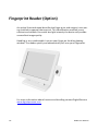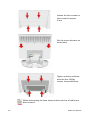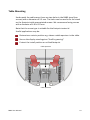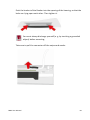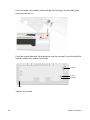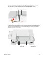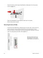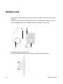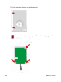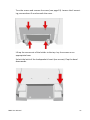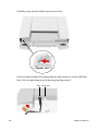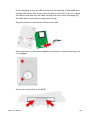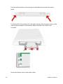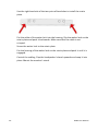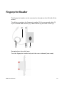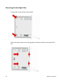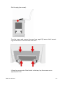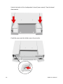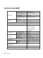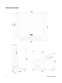
1
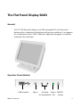
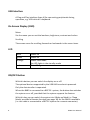
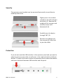
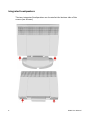
BA83 LCD TFT 15" (38,1 cm) Flat Panel Display User Manual User Manual BA83 We would like to know your opinion on this publication. Please send us a copy of this page if you have any constructive criticism. We would like to thank you in advance for your comments. With kind regards. Your Opinion: Wincor Nixdorf International GmbH Documentation RD HWD01 Wohlrabedamm 31 D-13629 Berlin E-Mail: [email protected] Order-No.: 01750158764H BA83 LCD TFT 15" (38,1 cm) Flat Panel Display User Guide Edition November 2013 All brand and product names mentioned in this document are trademarks of their respective owners. Copyright ©Wincor Nixdorf International GmbH, 2013 The reproduction, transmission or use of this document or its contents is not permitted without express authority. Offenders will be liable for damages. All rights, including rights created by patent grant or registration of a utility model or design, are reserved. Delivery subject to availability; technical modifications possible. Contents Introduction ................................................................................... 1 From Point-of-Sale To Point-of-Service ............................................. 1 Advantages At a Glance ..................................................................... 2 About This Manual ............................................................................. 2 The Flat Panel Display BA83 ........................................................... 3 General .............................................................................................. 3 Operator Panel Module ..................................................................... 3 USB Interface ..................................................................................... 4 On Screen Display (OSD) .................................................................... 4 LED ..................................................................................................... 4 ON/OFF Button .................................................................................. 4 Security .............................................................................................. 5 Protection .......................................................................................... 5 Integrated Loudspeakers ................................................................... 6 Capacitive Touch Screen ................................................................ 7 General .............................................................................................. 7 How To Operate ................................................................................. 7 Cleaning Instructions ......................................................................... 8 Infrared Touch Screen .................................................................... 9 General .............................................................................................. 9 How To Operate ................................................................................. 9 Cleaning Instructions ....................................................................... 10 Swipe Card Reader (Option) ......................................................... 11 How To Operate ............................................................................... 11 Cleaning Instructions ....................................................................... 12 Keyboard (Option) ....................................................................... 13 Cleaning Instructions ....................................................................... 13 Key Field ........................................................................................... 13 Exchanging the Keys ........................................................................ 14 Inserting Key Labels ......................................................................... 15 Inserting Key Caps ............................................................................ 15 Swipe Card Reader In a Keyboard (optional) ................................... 16 Waiter Lock (Option) .................................................................... 17 Fingerprint Reader (Option) ......................................................... 18 lnstalling and Securing ................................................................. 19 Unpacking And Checking the Delivery Unit...................................... 19 lnstalling the Base ............................................................................ 19 Table Mounting ................................................................................ 21 Mounting the Tube Adapter ......................................................... 22 Connection Bezel ............................................................................. 24 Connecting BA83 .............................................................................. 24 Dual Display Holder (Option)........................................................ 26 Mounting Positions ...................................................................... 27 Ergonomic Terminal Workplace ................................................... 28 Mounting Peripherals................................................................... 29 Keyboard And Swipe Card Reader ................................................... 29 Magnetic Swipe Card Reader........................................................ 36 Mounting On the Right Side ............................................................. 37 Mounting On the Left Side ............................................................... 42 Waiter Lock .................................................................................. 44 Mounting On the Right Side ............................................................. 45 Mounting On the Left Side ............................................................... 51 Fingerprint Reader ....................................................................... 53 Mounting On the Right Side ............................................................. 54 Mounting On the Left Side ............................................................... 59 On Screen Display (OSD) .............................................................. 61 Input Source ..................................................................................... 62 Display Setting .................................................................................. 63 Colour Setting................................................................................... 64 Image Setting (VGA Mode) .............................................................. 66 Tools Menu ...................................................................................... 68 Volume Setting ................................................................................. 69 EXIT OSD ........................................................................................... 70 Technical Data BA83..................................................................... 71 Dimensions (mm) ............................................................................. 72 Capacitive Touch Screen .................................................................. 73 Infrared Touch Screen ...................................................................... 73 Keyboard .......................................................................................... 73 MSR Inside Keyboard ....................................................................... 74 MSR Module .................................................................................... 74 Screen Driver Installation/ Installation Tool .................................... 75 Current Consumption Of the Screen Module .................................. 75 Programming the Keyboard And MSR .......................................... 76 Interfaces ......................................................................................... 76 Files .................................................................................................. 77 Modus .............................................................................................. 78 Creating Tables ................................................................................ 78 Software Interfaces ...................................................................... 79 Keyboard Codes (Standard) ............................................................. 79 Manufacturer’s Declaration And Approval ................................... 80 General Authorization ..................................................................... 80 FCC-Class A Declaration ................................................................... 80 Tested Safety ................................................................................... 81 Energy Star ....................................................................................... 81 User Information .............................................................................. 81 Safety Information ........................................................................... 81 Warranty .......................................................................................... 82 Instructions For Maintenance .......................................................... 83 Recycling .......................................................................................... 83 Abbreviation Index ...................................................................... 85 Introduction From Point-of-Sale To Point-of-Service With the BA83 you are using a ergonomical and customer-friendly cashier's workplace. The BA83 is connected to the system via a VGA or DVI interface. Power is supplied via a PoweredUSB interface or an external power supply unit. The Touch screen as well as the USB Hub are contolled via a USB cable or via a PoweredUSB cable. The display can be applied in all trade market segments like specialist retailers, department stores, self-service stores, petrol stations or in restaurants. There is indeed a great deal of scope for implementing the BA83. They can be used, for example, as: a point-of-sale terminal an ordering terminal an information terminal a desk terminal. The low-energy, flickerfree and radiation-free colour monitor of the BA83 is a LCD in TFT-technology (Thin Film Transistor). Therefore, it is well suited for multimedia applications as it offers brilliant colour representation, an excellent contrast ratio and a high display speed. BA83 User Manual 1 Advantages At a Glance low footprint Autoscaling of the screen Flickerfree and free from radiation Very good contrast ratio, adjustable loudness, sharpness, width, phase, colour temperature and brightness via OSD menu LCD TFT technology with LED backlight Digital interface simple installation via plug & play feature Mounting VESA 75 & 100 standard integrated loudspeaker USB interface for external devices. About This Manual This manual informs you about everything you might need to know for the installation (software and hardware), the operation and the maintenance of your BA83. This description refers to the version BA 83/e (see type label on the device). Same parts of this book require familiarity and experience in working with operating systems and installation and configuration procedures. Notes in the manual are marked by this symbol. This symbol is used for warnings. 2 BA83 User Manual The Flat Panel Display BA83 General The TFT LCD flat panel display is an XGA-compatible 15-inch flat panel display which is absolutely flickerfree and free from radiation. lt is designed for a resolution of max. 1024 x 768 pixel. Application programs should be used with this resolution! Operator Panel Module USB interface BA83 User Manual Menu Scrolling Status ON/OFF for-/backwards LED button 3 USB Interface A Plug and Play interface (type A) for connecting peripherals during operation, e.g. USB sticks or a keyboard. On Screen Display (OSD) Menu Via the menu you can set the loudness, brightness, contrast and colour. Scrolling The arrows serve for scrolling forwards or backwards in the menu items. LED dark green orange red Power off Power on Power save mode the LED lights in the standby mode Out of Range ON/OFF Button With this button you can switch the display on or off. The optional devices supported by the USB HUB are electric powered. Only the data transfer is separated. When the BA83 is connected to a BEETLE- system, the button also switches the system on or off, provided that the system supports the feature. With this key you can switch the system into 'Wake up Mode' or 'Sleep Mode' provided a Remote function (see page 18) for the BA83 is available (i.e. the cable is connected to a BEETLE system via a remote connector). 4 BA83 User Manual Security The operator panel module can be mounted horizontally turned thus to handicap the access. Slightly press the module inwards at the left and right hand side (1). Remove the module of the recesses and carefully move it off downwards (2). Carefully turn the device through 180° (3). Reinsert the module into the recesses (4). Mind not to jam the cables. Protection If you do not need the USB interface in the operator panel and you want to close the port you can order a small cover in the required colour at Wincor Nixdorf. To attach this bezel remove the operator panel as described above and insert the bezel between USB interface and the panel. BA83 User Manual 5 Integrated Loudspeakers The two integrated loudspeakers are located at the bottom side of the screen (see arrows). 6 BA83 User Manual Capacitive Touch Screen General The TFT Touch Screen works according to the principle of a change in analog capacitance. It has a glass screen with a transparent, thin-film over lay on the surface. This is fully sea led and protected by a further layer of clear glass. Electrodes on the edges of the screen provide an uniform lowvoltage field. As soon as you touch the screen with your finger the contact point is “recognized” by the change in capacitance. Conductive product layer Clear glass cover Because this happens very quickly, the Touch Screen is optimally equipped for a number of different requirements and applications. The programming interface of the screen is identical to the mouse interface. Connecting a BA83 for the first time, we recommend that you calibrate the Touch Screen. Details depend on the Operating System that you use. How To Operate The Touch Screen responds to the slightest contact, therefore you do not have to apply pressure when working with the screen. Touching the touch BA83 User Manual 7 glass has the same effect as clicking the left mouse button. You only need to apply a little pressure with the fingertip. In this capacitive process only fingertip contact is recognized. The touch screen does not react in any way if touched, for example, with a pen. Cleaning Instructions Always turn off the system before cleaning. The glass surface of your Touch Screen should be cleaned with a mild, abrasive free, commercially available glass cleaning product. All pH neutral materials (pH 6 to 8) are good for cleaning. Cleaners with pH values 9 to 10 are not recommended. Cleaning with water and isopropyl alcohol is possible as well. Do not use solvents containing acetic acid. Use a soft, fine-meshed cloth to clean the surface. Dampen the cloth slightly and then clean the screen. A wrong maintenance may cause damages to the screen, which are not covered by guarantee or warranty. 8 BA83 User Manual Infrared Touch Screen General The infrared (IR) technology is based on the interruption of a grid of IR light beams before the surface of a screen. The touch frame contains a row of infrared light emitting diodes (LEDs) and photo transistors, each mounted on two opposite sides to create a grid of invisible infrared light. How To Operate 1 2 3 4 Touch Activation Receiver Active Display Area Transmitter IR light beams are produced and transmitted over the surface of the screen. The photo sensors accept the beams. When an object (min. 8mm Ø), such as a finger, enters the hidden grid, it obstructs the beams. One or more photo sensors detect the absence of light and transmit a signal, that identifies the x and y coordinates. BA83 User Manual 9 Breaking through the grid has the same effect as clicking the left mouse button. Therefore, touching the glass is not necessary. To avoid malfunctions: Do not fix labels or stickers on the frame and do not put pencils or the like on the inner frame. Cleaning Instructions Always turn off the system before cleaning The glass surface of your Touch Screen should be cleaned with a mild, abrasive free, commercially available glass cleaning product. All pH neutral materials (pH 6 to 8) are good for cleaning. Cleaners with pH values 9 to 10 are not recommended. Cleaning with water and isopropyl alcohol is possible as well. Do not use solvents containing acetic acid. Use a soft, fine-meshed cloth to clean the surface. Dampen the cloth slightly and then clean the screen. A wrong maintenance may cause damages to the screen, which are not covered by guarantee or warranty. 10 BA83 User Manual Swipe Card Reader (Option) The swipe card reader (MSR Module), that is available as an option, can read three ISO tracks simultaneously in a single swipe. The MSR module is fitted on the right-hand or left-hand side of the keyboard module or screen module. How To Operate Run the swipe card through the slit of the swipe card reader from top to bot tom in a quick and steady movement. Make sure that the magnetic strip is to the right. When using swipe cards, the following should be observed: Swipe cards should never be allowed to come into contact with liquids. Swipe cards should not be bent or folded in any way. Swipe cards should not be allowed to come into close contact with a magnetic field. Swipe cards should only be inserted in the top of the specially designed slit of the reading device. If the card is inserted in another place, this could damage the reading head. BA83 User Manual 11 Cleaning Instructions In order to guarantee good reading results, the swipe card reader should be cleaned from time to time. This is carried out by using a special cleaning card that can be purchased from Wincor Nixdorf. 12 BA83 User Manual Keyboard (Option) The keyboard is connected directly to the display via a USB interface. It is fitted to the right-hand side of the screen. The keyboard is available with or without a swipe card reader. Cleaning Instructions The keyboard should be cleaned with a germicide from time to time. Before cleaning in between the keys on the keyboard with a brush, loosen and remove the key caps using the key removing device. Do not allow dust to get in through the open keyboard mechanics. Key Field The key field comprises of max. 32 freely assignable keys. BA83 User Manual 13 Exchanging the Keys You can remove each of the key caps using the key removal device enclosed, pulling the key upwards. Place the key removal device on the selected key until you hear a click. Now remove this key from the keyboard by pulling it upwards. If the key that has been removed is already labelled you can change the lettering as follows: By using a thin object (e.g. paper-clip etc.), press upwards against the plastic cover through the opening on the underside of the key. Please refer to the next chapter for instructtions on how to insert the new label. 14 BA83 User Manual Inserting Key Labels Below you will find instructions on how to insert the key labels: Each key should be labeled individually. You can use the empty labels delivered with the system to do so. Key cover with mat side up Place the label on the key cap. Labels for keys Key cap Insert the key cover with the mat side upwards until it clicks into place in the key cap. Inserting Key Caps Insert the key cap in the keyboard and press it firmly into place. BA83 User Manual 15 actuating cylinder When inserting double keys, please ensure that the actuating cylinder is on the left (horizontally inserted key) resp. on top (vertically insertion). Mind to insert quadruple key caps with the cylinder on the upper left. Swipe Card Reader In a Keyboard (optional) The keyboard is available with or without a Swipe Card Reader. This module corresponds to the module "Swipe Card Reader". For technical data see the accordant chapter on page 74. Technical data of the separate Swipe Card Reader comply with the data of the Swipe Card Reader integrated in the keyboard. 16 BA83 User Manual Waiter Lock (Option) Each transaction is correctly assigned to the personnel by using the magnetic key. The magnetic keys are available in 10 different colors. The magnet keys are waterproof, shatterproof and by the 16-digit key number also safe for clear identification. The operation of the system is very simple, the key is placed onto the magnetic probe (see figure). The key is held magnetically to the probe and transmits the data by an electrical USB interface. The readout of the data may be integrated easily in a software application. Magnetic probe Programming the "Electronic Key Controller" for the Waiter's Lock is described in a separate "Programmer's Guide". BA83 User Manual 17 Fingerprint Reader (Option) An optical Scan technique identifies the finger print and assigns it to a person entitled to operate the terminal. This identification method is very efficient and reliable. Even with low light intensity the device will provide an excellent image quality. Handling is very comfortable. Just put your finger on the blue glowing window. The reader quickly and automatically will scan your fingerprint. For more information about function and handling contact DigitalPersona www.digitalpersona.com 18 BA83 User Manual lnstalling and Securing Unpacking And Checking the Delivery Unit Unpack the parts and check to see whether the delivery matches the information on the delivery note. The delivery comprises the respective screen module. Data cables, necessary for operation, can be ordered separately. lf damage has occurred during shipping or if the package contents do not match the delivery note, immediately inform your Wincor Nixdorf sales outlet. Transport the device only in its original packaging (to protect it against impact and shock). lnstalling the Base Take the base and the screen out of the packaging. For installation you will need a Phillips head screwdriver to loosen and tighten the screws! Move the bezel (1) out of the guidance of the screen element. ① Remove the base cover (2) in direction of arrow. ② BA83 User Manual 19 Loosen the four screws on the screen for approx. 2 mm. Put the screen element on to the base. Tighten monitor and base with the four Phillips screws, loosened before. When demounting the base always make sure that all cables are disconnected. 20 BA83 User Manual Table Mounting Underneath the cable cover there are two holes in the BA83 stand (see arrows) with a diameter of 5.5 mm. The holes can be used to fix the stand on the footprint with appropriated screws. We recommend using screws with a diameter of 4.0 to 5.0 mm. Note that the screw type is suitable for the footprint material. Useful applications may be: Determine a certain position e.g. above a cable aperture in the table. Secure the display stand against “theft by passing”. Protect the install position on a tilted footprint Cable aperture Cable aperture BA83 User Manual 21 Mounting the Tube Adapter Take the tube adapter out of the cardboard box and lay it next to the display. For the mounting you need a Phillips head screwdriver for fixing and releasing the screws. Pull the cover downwards (see pages 19). Loosen four screws at the rear side of the BA83 and put them aside. Mount the tube adapter on the rear side of the BA83 and fix it with the previously removed screws. 22 BA83 User Manual After cabling the display put on the optional available cover. Put the display with the adapter on the preinstalled tube (1) and fix it with the screw (2). ② ① BA83 User Manual 23 Connection Bezel The following sockets are located under the bezel of the screen: USB- A PoweredUSB DC Power Jack/12V (12V) DVI- I RJ10 (RMT) USB- A For external peripherals, can be used for MSR PoweredUSB Data transfer and/or current supply for the screen via system e.g. BEETLE Power Jack Current supply for the screen via external power pack (12V) DVI-I DVI or VGA data transfer from TFT display to the system RJ10/RMT RMT, "Remote", serves the on/off activation of the BEETLE system. Corresponds to the function of the On button at the BEETLE system. If the power is not supplied by a BEETLE system you have to use an external power supply unit. Only UL Listed LPS (Limited Power Source) power supplies can be used. By connecting the system's cable the screen will be switched on. Connecting BA83 Remove the bezel of the monitor and the cable cover of the base. Before connecting cables switch off the system and disconnect it from the mains supply. 24 BA83 User Manual When laying this cable please mind to slightly clamp it (with a loop) into the strain relief. Lay the cable into the guidance inside the base. Lay a USB-A cable loosely-fitting into the strain relief. When passing the cables please mind the following maximal cable diameters (in mm). Fix cable with the strain relief (see arrows). Reinsert the cable cover and the bezel. BA83 User Manual 25 Dual Display Holder (Option) The Dual Display Holder offers the possibility to mount a customer display to the rear side of a cashier display. This option needs little space so that you can use your workplace in an optimized way. The holder is screwed to a main display via a hanging (VESA), while the main display is placed on a foot. The second display (here the BA80) is to be hinged and fixed with screws (see installation manual BA8x, Dual Display Holder). Likewise, you can continue a BA82 with another BA82 or a BA82 with a BA83. A clever cable management not only prevents a cable disorder but adds an elegant impression to the device. BA83/BA80 26 BA83 User Manual Mounting Positions There are three mounting positions. Two (at the left and right hand side) can be used to install Magnetic Card Reader; a keyboard may be installed at the right hand side. The third position is located above the screen. Other units (e.g. a camera, not available at that time) can be installed above the screen. BA83 User Manual 27 Ergonomic Terminal Workplace Please observe the following when setting up your terminal workplace: Avoid direct glaring and reflective glaring. Use the screen only in a controlled luminance surounding. Install the device with a viewing directi on that is parallel to the windows. Avoid reflective glaring caused by electric light sources. permitted range of vision 0° 40° 30° Position the screen within a preferred and permit ted range of vision, so that you can look vertically onto the screen. 30° preferred range of vision 28 BA83 User Manual Mounting Peripherals Unpack the parts and check whether the delivery matches the details of the delivery note. Keyboard And Swipe Card Reader The delivery contains the keyboard with Swipe Card Reader (SCR), the connected cable, the pre-installed holder (BA83), the holder of the BA82, two screws and a set of keys including a key remover. keyboard, SCR, cable and holder BA83 holder BA82 Do not release the loop! Turn the keyboard and push the cover aside (see arrow). BA83 User Manual 29 Loosen the two screws (see arrows) and remove the bracket. Turn the screen around and remove the bezel (see page 19). Loosen the screws beneath the cover. Lift the screen out of the holder to the top. Lay the screen on an appropriate base. 30 BA83 User Manual Loosen the snap arms of the loudspeaker's bezel (see arrows). Flap the bezel downwards. Carefully press out the blind screen from inside. BA83 User Manual 31 Push the bracket into the opening of the housing, so that the holes are lying upon each other. Tighten with two (delivered) screws. You must always discharge yourself (e. g. by touching a grounded object) before mounting. Take care to pull the connector off the keyboard. 32 BA83 User Manual Pass the keyboard cable through the housing into the cable guidance and connect it. Push keyboard beneath the bracket. Take care that the upper parts of the hooks (see arrows) are above the plate! Mind that the screws match with the keyholes. keyholes screw Tighten the keyboard. BA83 User Manual 33 If you are going to use the USB interface at the backside of the BA83 then run the cable loosely through the strain relief as shown below. Put the cable loop into the housing. OSD cable connection keyboard cable connection If a device has a second hub, you can connect the keyboard at the next free port on the hub. To do so, release the cable's loop and run the cable through the strain relief. strain relief 34 USB interfaces BA83 User Manual Insert the cover of the keyboard as shown below. The metal bar is corresponding to the gap (1) and push it to the housing until it is engaged (2). ② ① Flap the loudspeaker's bezel upwards and snap it into place. Mount the monitor's stand. BA83 User Manual 35 Magnetic Swipe Card Reader The Magnetic Swipe Card Reader can be mounted on either the right or the left side of the screen. The delivery contains the Swipe Card Reader (SCR), the connected cable, the pre-installed holder (BA83), a holder (BA82) and two screws. SCR, cable and holder BA83 holder BA82 Do not release the cable loop. Turn the Swipe Card Reader and push the cover side wards (see arrow). 36 BA83 User Manual Mounting On the Right Side Loosen the Torx screws and remove the bracket. Turn the screen and remove the cover (see page 19). Loosen and remove the screws beneath the cover. Lift the screen out of the holder to the top. BA83 User Manual 37 Loosen the snap arms of the loudspeaker's bezel (see arrows). Flap the blind bezel downwards. Carefully press out the blind screen from inside. 38 BA83 User Manual Push the bracket of the Reader into the opening of the housing, so that the holes are lying upon each other. Then tighten it. You must always discharge yourself (e. g. by touching a grounded object) before mounting. Take care to pull the connector off the swipe card reader. BA83 User Manual 39 Pass the swipe card reader cable through the housing into the cable guidance and connect it. Push the reader beneath the bracket so that the screws fit into the keyhole and the holder lays under the clamps. clamp screw keyhole clamp Tighten the screws. 40 BA83 User Manual Pass the cable loosely through the cable guidance and connect it to the USB interface. Put the cable loop into the housing (see big arrow) OSD swipe card reader If a device has a second Hub, you can connect the swipe card reader at the next free port on the Hub. To do so, release the cable's loop and run the cable through the strain relief. strain relief BA83 User Manual USB interfaces 41 Attach the cover of the Swipe Card Reader (1) and push it to the monitor until it engages (2). ② ① Flap the loudspeaker's bezel upwards and snap it into place. Mount the monitor's stand. Mounting On the Left Side Proceed as described above ("Mounting on the right side"). Disconnect the cable to connect it to the USB interface at the rear side of the monitor. Push the bracket of the Reader into the opening of the housing, so that the holes are lying upon each other. Then tighten it. Pass the cable into the cable guidance of the Swipe Card Reader and connect it. 42 BA83 User Manual Push the reader beneath the bracket, so that the screws fit into the keyhole and the holder lays under the clamps. Tighten the screws. Pass the cable through the cable guidance and connect it to the USB interface. If a HUB is available you should use one of it's USB interfaces. Do not release the cable loop. clamp clamp Attach the cover of the swipe card reader and push it to the monitor until it engages. Flap the loudspeaker's bezel upwards and snap it into place. Mount the monitor's stand. BA83 User Manual 43 Waiter Lock The waiter lock can be mounted on either the right or the left side of the screen. The delivery contains the waiter lock (1), the connected cable (2), a preinstalled BA83 holder (3); a BA82 holder (4) and two screws (5). ⑤ ② ④ ③ ① Do not release the cable loop. Turn the waiter lock and push the cover sideward (see arrow). 44 BA83 User Manual Mounting On the Right Side Loosen the screws of the retain plate. Move the retain plate out of the guide in direction of the arrows and lift it up. BA83 User Manual 45 Pull the electronic element out of the housing. You must always discharge yourself (e. g. by touching a grounded object) before mounting. Loosen the screws and pull the plug. 46 BA83 User Manual Turn the screen and remove the cover (see page 19). Loosen the 4 mounting screws about 3 mm beneath the cover . Lift up the screen out of the holder to the top. Lay the screen on an appropriate base. Unlock the latch of the loudspeaker's bezel (see arrows). Flap the bezel downwards. BA83 User Manual 47 Carefully press out the blind screen from inside. Pass the cable through the cable guidance and connect it to the USB interface. Put the cable loop into the housing (see big arrow). OSD waiter lock 48 BA83 User Manual If you are going to use the USB interface at the backside of the BA83 then connect the waiter lock to any free interface at the HUB. To do so, release the cable's loop and run the cable through the strain relief (see page 41). Pass the waiter lock cable through the housing. Plug the jack to the connection of the waiter lock. Screw electronic and element together and clamp it into the housing until it is engaged. Screw the retain plate at the BA83. BA83 User Manual 49 Use the left borehole of the two pairs of boreholes to install the retain plate. Put the cable of the waiter lock into the housing. Slip the waiter lock on the retain plate and push it backwards. Make sure that the cable is not crimped. Screw the waiter lock to the retain plate. 50 BA83 User Manual Put the housing of the waiter lock on the retain plate and push it until it is engaged. Control the cabling. Flap the loudspeaker's bezel upwards and snap it into place. Mount the monitor's stand. Mounting On the Left Side Proceed as described above ("Mounting on the right side", page 45ff). Fasten the retain plate of the waiter lock on the opening of the housing rotated 180°. BA83 User Manual 51 Use the right borehole of the two pairs of boreholes to install the retain plate. Put the cable of the waiter lock into the housing. Slip the waiter lock on the retain plate and push it backwards. Make sure that the cable is not crimped. Screw the waiter lock to the retain plate. Put the housing of the waiter lock on the retain plate and push it until it is engaged. Control the cabling. Flap the loudspeaker's bezel upwards and snap it into place. Mount the monitor's stand. 52 BA83 User Manual Fingerprint Reader The fingerprint reader can be mounted on the right or the left side of the screen. The delivery contains the fingerprint reader (1), the connected cable (2), a pre-installed BA83 holder (3); a BA82 holder (4) and two screws (5). ⑤ ② ④ ③ ① Do not release the cable loop. Turn the fingerprint reader and push the cover sideward (see arrow). BA83 User Manual 53 Mounting On the Right Side Loosen the screws of the retain plate. Move the retain plate out of the guide in direction of the arrows and lift it up. 54 BA83 User Manual Pull the plug (see arrow). Turn the screen and remove the cover (see page 19). Loosen the 4 mounting screws about 3 mm beneath the cover . Lift up the screen out of the holder to the top. Lay the screen on an appropriate base. BA83 User Manual 55 Unlock the latch of the loudspeaker's bezel (see arrows). Flap the bezel downwards. Carefully press out the blind screen from inside. 56 BA83 User Manual Pass the cable through the cable guidance and connect it to the USB interface. Put the cable loop into the housing (see big arrow). OSD fingerprint reader If you are going to use the USB interface at the backside of the BA83 then connect the fingerprint reader to any free interface at the HUB. To do so, release the cable's loop and run the cable through the strain relief. Pass the fingerprint reader cable through the housing. Screw the retain plate at the BA83. Use the left borehole of the two pairs of boreholes to install the retain plate. Plug the jack to the connection of the fingerprint reader. BA83 User Manual 57 Put the cable of the fingerprint reader into the housing. Slip the fingerprint reader on the retain plate and push it backwards. Make sure that the cable is not crimped. Screw the fingerprint reader to the retain plate. 58 BA83 User Manual Put the housing of the waiter lock on the retain plate and push it until it is engaged. Control the cabling. Flap the loudspeaker's bezel upwards and snap it into place. Mount the monitor's stand. Mounting On the Left Side Proceed as described above ("Mounting on the right side", page 54ff). Fasten the retain plate of the waiter lock on the opening of the housing rotated 180°. BA83 User Manual 59 Use the right borehole of the two pairs of boreholes to install the retain plate. Put the cable of the fingerprint reader into the housing. Slip the fingerprint reader on the retain plate and push it backwards. Make sure that the cable is not crimped. Screw the fingerprint reader to the retain plate. Put the housing of the fingerprint reader on the retain plate and push it until it is engaged. Control the cabling. Flap the loudspeaker's bezel upwards and snap it into place. Mount the monitor's stand. 60 BA83 User Manual On Screen Display (OSD) A set of 4 buttons is located at the operator panel module. Menu select left right scrolling Power Pressing the menu button will activate the OSD. Depending on the selected function, a sub- menu option will be available for a selection on the same screen. There are two ways to exit the OSD menu: via exit or wait for the OSD to time-out (saves changes and exit). The adjustments will be saved in each way. There are a number of parameters that can be set via the OSD menu. In the following all the selectable parameters that can be set via various OSD sub menus are shown. BA83 User Manual 61 Input Source The Input Source indicates the active video channel. BA83e analog input (VGA) digital input (DVI) Exit sub menu 62 BA83 User Manual Display Setting BA83e brightness sub menu: contrast sub menu: If the contrast is set too high, bright surfaces can no longer be distinguished from very bright surfaces. If the contrast is set too low, the maximum brightness will not be achieved. Exit sub menu BA83 User Manual 63 Colour Setting The colour setting is only adjustable in the normal running temperature. The display must run at least 20 minutes. BA83e Auto Colour (auto colour adjustment at VGA mode only) sRGB settings standard RGB settings Colour temperature Choose the colour temperature in the sub menus, measured in K (Kelvin). Choose "factory settings" in the Tools menu to set the original settings again. 64 BA83 User Manual Sub menu colour temperature RGB Setting manual setting There are 5 basic settings: 4200K 5000K 6500K (setting, for example for image processing or playing DVD) 7500K 9300K (setting for CAD/CAM applications) Exit sub menu Exit menu BA83 User Manual 65 Image Setting (VGA Mode) BA83e Auto scaling (auto adjustment) Should the image setting be faulty during the initial operation this function will adjust the image if necessary you operate "Auto colour" in addition. width sub menu Phase Regulates the sampling rate for transfer the analog amplifier into digital signals. This setting allows to produce a sharp image. Sub menu 66 BA83 User Manual Horizontal position sub menu Vertical position sub menu exit sub menu BA83 User Manual 67 Tools Menu BA83e Factory setting No reset of Image Setting (Screen width, phase, horizontal/vertical position) After reset to factory setting at VGA mode: it is absolutely necessary to operate "Auto colour" (see page 64), you can operate "Auto scaling" in addition (see page 66). Sharpness The setting upgrades the contour of a blurred text by a lower solution. sub menu Time out For adjusting the time interval (scale from 1 up to 16 seconds) for displaying the OSD. With time elapsed OSD will be closed sub menu 68 BA83 User Manual Information about firmware version Exit sub menu Volume Setting BA83e volume sub menu exit sub menu BA83 User Manual 69 EXIT OSD BA83e 70 BA83 User Manual Technical Data BA83 Dimensions Weight Diagonal Screen size Active screen size (horizontal x vertical) Cable length Dimensions Display Housing w/o base With base Climate class Operating temperature Humidity Frequencies Solutions Horizontal (KHz) Vertical (Hz) Horizontal Vertical Colour depth Pixel Format internal extern Reading Angle, right/left top/ bottom Inerface Brightness Backlight BA83 User Manual 15"(38.1 cm) 304 mm x 228 mm up to 3m 368 x 300 x 90 mm 4.5 kg 6.7 kg IEC 721 3/3 Class 3K3 +5 °C- + 40 °C 5%-85% Absolute humidity 1g/m3 - 25g/m3 Condensation is not permitted typ. 48.3 typ. 60 1024 Pixel 768 Pixel Up to 16.7 Mio. Approx. 0.30 mm x 0.30 mm LVDS DVI-I +/- 80 ° 70 ° typ. 330 cd/m2 LED 71 Dimensions (mm) 72 BA83 User Manual Capacitive Touch Screen Resolutions Horizontal Vertical 16k 16k Analog capacitive anti reflection (capacitiv) typ. 300 cd/m² USB Horizontal Vertical 4096 pixel 4096 pixel Infrared touch anti-reflection typ. 300 cd/m² USB LCD Technology Surface Brightness Data transfer Infrared Touch Screen Resolutions LCD technology Surface Brightness Data transfer Keyboard Protocol Power supply Connection Keyboard Height Width (mounted at the screen) Depth Weight BA83 User Manual HID 1.1 (Human Interface Device) USB Bus-powered USB- A (USB 2.0 compliant) 32 keys, freely assignable 179 mm 140 mm 40mm Approx. 800g 73 MSR Inside Keyboard Number of tracks Coding of swipe cards Reading speed up to 3 according to 1807811-2 10 to 140 cm/sec. MSR Module Power supply Connection Protocol Number of tracks Coding of swipe card reader Reading speed Height Width (Screen mounted) Depth Weight 74 USB Bus powered USB-A (USB 2.0 compliant) HID 1.1 (Human Interface Device) up to 3 according ISO 7811-2 10 to 140 cm/sec. 179 mm 51 mm 40 mm approx. 31Og BA83 User Manual Screen Driver Installation/ Installation Tool Drivers are available for the following operating systems: Windows: Windows XP, WEPOS Linux: WNLPOS You can find detailed information about the driver installation in the Read me file on the internet. http://www.wincornixdorf.com/internet/site_EN/EN/Support/Downloads/POSLotterySystems/Dr iver/driver_node.html The basic functions for both the capacitive Touch Screen and the infrared Touch Screen do not require any drivers as the two screens are USB-HID devices. Drivers are available for additional functionality. For the capacitive Touch Screen only install drivers as of version MT7.13.4. The driver installation is necessary for the operating system Linux. Calibrate the Touch Screen when you connected it for the first time. Current Consumption Of the Screen Module The maximum power input of the BA83 is 2.6 A (12VDc). Power consumption (nominal) Power consumption (Standby) Power consumption (Soft off) BA83 User Manual < 10 W < 1W < 0.5 W 75 Programming the Keyboard And MSR Utility KbUtiUSB is used for Programmable Wincor Nixdorf Keyboards with a USB HID interface. Programmability of Keyboard and Magnetic Swipe Card Reader (MSR) allows to adapt them to special needs. So you can: define special start and end codes for the tracks of the Magnetic Stripe Reader, in which case the data of the several tracks still con form to standard ISO 7811 define arbitrary codes or strings of codes for the keys port your existing application software with much less effort, as the interface to the Magnetic Stripe Reader and Keyboard still may be valid. Interfaces There are three interfaces: Keyboard interface (handled by operating system) MSR Interface (normally handled by application interface, e.g. OPOS, JavaPOS, etc) Firmware Update Interface (handled by Firmware Update Utility As the keyboard interface is serviced by the operating system, normally only keyboard is programmed, as the HID interface to the MSR is in most cases serviced by an OPOS Service Object, a JavaPOS Device Service, etc. It is, however, possible to program the MSR as well, e.g. if you want to get the same codes for the BA83 MSR (having a USB HID interface) compared to an already existing customer’s MSR (which has e.g. a PS/2 interface).PS/2 Interface). 76 BA83 User Manual Files On the Wincor Nixdorf Internet site you can find the KbUtiUSB package. This package is written in Java and therefore there is a version for Windows and for WNLPOS (Wincor Nixdorf’s Linux Distribution). KbUtiUSB requires at least a Java Runtime Version 1.4.2_06. KbUtiUSB provides different modes of operation dependent on how it is started: No Batch Mode Parameter dialog utility for programming keyboard or even MSR -s parameter send a table to keyboard or even MSR from a file (batch mode) -r parameter receive table from keyboard or even MSR to a file (batch mode) -c parameter check if keyboard/ MSR is prgrammed (batch mode) -d parameter reset keyboard/ MSR to default (batch mode) Return codes of KbUtiUSB running in batch mode indicate if operation was OK rsp. which error occurred. By convention files containing tables have the extension ‘.kbu’. In some cases the power supply to the BA83 would have to bedisconnected thus causing a reboot and the import of the new settings. Alternatively, you can use the SW command to activate the "MSR legacy mode". This will transfer the programmed data without having to reboot the MSR. For further details see: http://intranet.wincor-nixdorf.com/cms/intranet/Products/ RetaiI_Division/epos_and_periph/peripherals/displays/userdisplays/ba83/kbutiusb BA83 User Manual 77 Modus Keyboard and MSR may have two different states: “Default” This is the default state of keyboard and MSR, codes are assigned by firmware “Programmed” In this case a table has been sent to keyboard or even MSR Creating Tables Tables can be created and sent / received using KbUtiUSB under Windows or WNLPOS. At first a configuration has to be defined consisting of: Kind of level handling to be provided for keyboard The number of levels to be supported for keyboard The target keyboard language The type of the target device (here: BA8X keyboard) Definition of codes is easy, as a Virtual Keyboard is used to define them. There is no need to worry about codes, key symbols, syntax, etc. Just press the keys of the Virtual Keyboard to get the codes or code strings entered. There is provision of the differences between a US keyboard (101 keys) or other keyboard (102 keys). Assigned codes can be viewed one by one or the table as a whole. This information can also be written to a text file for documentation. 78 BA83 User Manual Software Interfaces Keyboard Codes (Standard) (F1) 3B 3B 00 (F2) 3C 3C 00 (F3) 3D (F4) 3E 3E 00 (F5) 3F 3F 00 (F6) 40 40 00 (F7) 41 41 00 (F8) 42 42 00 (F9) 43 43 00 (F10) 44 44 00 (Clft) E0,4B 4B E0 (PgUp) C E0,49 49 E0 7 47 47 37 4 4B 4B 34 1 4F 4F 31 0 52 52 30 (ESC) 01 01 1B (s) 1F 1F 73 (Crgt) E0,4D (PgDn) E0,51 51 E0 (BS) 0E 0E 08 (u) 16 16 75 (Y) 15 15 79 (n) 31 31 6E 8 48 48 38 5 4C 4C 35 2 50 50 32 . 53 53 2E 9 49 49 39 6 4D 4D 36 3 51 51 33 (CR) 1C 1C 0D Scan Code of the keyboard controller * Note: Free key labelling; constant key function. BA83 User Manual 79 Manufacturer’s Declaration And Approval General Authorization This device complies with the requirements of the di rective 2004/108/EC with regard to “Electromagnetic Compatibility” and 2006/95/EC "Low Voltage Directive". Therefore, you will find the CE mark on the device or packaging. FCC-Class A Declaration This equipment has been tested and found to comply with the limits for a Class A digital device, pursuant to part 15 of the FCC Rules. These limits are designed to provide reasonable protection against harmful interference when the equipment is operated in a commercial environment. This equipment generates, uses, and can radiate radio frequency energy and, if not installed and used in accordance with the instruction manual, may cause harmful interference to radio communications. Operation of this equipment in a residential area is likely to cause harmful interference in which case the user will be required to correct the interference at his own expense. Modifications not authorized by the manufacturer may void users authority to operate this device. This class A digital apparatus complies with Canadian ICES-003. Cet appareil numerique de la classe A est conforme à la norme NMB-003 du Canada. 80 BA83 User Manual Tested Safety The BA83 has been awarded the cUL- and UL- symbol. Energy Star The BA83 has been awarded the ENERGY STAR symbol. User Information Repair work on the devices should only be carried out by authorized and specially trained personnel. Improper repairs will lead to the loss of any guarantee and liability claims. Extension boards with electrostatically endangered components can be identified with this label. Safety Information This device conforms to the corresponding safety regulations for information technology devices, including electronic office machines for use in the office environment. If the device is moved from a cold environment to a warmer room where it is to be operated, condensation could occur. The device must be completely dry before being put into operation. Therefore an acclimatization time of at least two hours should be accounted for. Lay all cables and supply lines so that nobody can tread on them or trip over them. BA83 User Manual 81 Data cables should neither be connected nor removed during electrical storms. Protect the device from vibrations, dust, moisture and heat, and only transport the device in its original packaging (to protect it against impact and blows). Take care to ensure that no foreign objects (e.g. paper clips) or liquids can get into the inside of the device, as this could cause electrical shocks or short circuits. In case of emergencies (e.g. damaged housing, liquid or foreign objects getting into the device), the device should be switched off immediately, the mains plug of the BEETLE or PC should be removed, and the Wincor Nixdorf customer service should be contacted. If the LCD display element is broken and the liquid crystal solution leaks out of the display and onto your hands, clothing etc., wash your hands or clothing immediately with soap or alcohol, holding them under running water for at least 15 minutes. If the liquid comes into contact with your eyes, please consult a doctor immediately. Generally you should connect IT-devices only to power supply systems with separately guided protective earth conductor (PE), known as TN-S networks. Do not use PEN conductors! Please also observe the recommendations of the norm DIN VDE 0100, part 540, Appendix C2, as well as EN50174-2, §5.4.3.. Warranty Wincor Nixdorf guarantees generally a warranty engagement for 12 months beginning with the date of delivery. This warranty engagement covers all those damages which occur despite a normal use of the product. Damages because of improper or insufficient maintenance, improper use of the product or unauthorized modifications of the product, 82 BA83 User Manual inadequate location or surroundings will not be covered by the warranty. For further information of the stipulation look at your contract. All parts of the product which are subject to wear and tear are not included in the warranty engagement. Please order spare parts at the Wincor Nixdorf customer service. Instructions For Maintenance Clean your BA83 regularly with an appropriate surface cleaning product. Make sure that the device is switched off, connector cables are unplugged and that no moisture is allowed to get into the inside of the device. Please observe the maintenance and cleaning instructions for each of the BA83 components. These instructions can be found in their respective chapters. Recycling Environmental protection does not begin when time comes to dispose of the BEETLE; it be gins with the manufacturer. The compact BA83 is manufactured without the use of CFCs and CCHS and is produced mainly from reusable components and materials. The processed plastics can, for the most part, be recycled. Even the precious metals can be recovered, thus saving energy and costly raw materials.Please do not stick labels onto plastic case parts. This would help us to re-use components and material. You can protect our environment by switching on your equipment only when it is actually needed. If possible, even avoid the stand-by-mode as this wastes energy, too. Also switch your equipment off when you take a longer break or finish your work. There are still some parts that are not reusable. Wincor Nixdorf guarantees the environmentally safe disposal of these parts in a Recycling Center, which is certified pursuant to ISO 9001 and ISO 14001. BA83 User Manual 83 So don’t simply throw your device on the scrap heap when it has served its time, but take advantage of the environmentally smart, up-to-date recycling methods! Please contact your competent branch or the Recycling Center Paderborn (for European countries) for information on how to return and re-use devices and disposable materials under the following mail address: Email: [email protected] We look forward to your mail. 84 BA83 User Manual Abbreviation Index CE cUL DIN DVI-I EKC EMI EN ESD GS IEC IR ISO LCD LED LVDS MSR OSD POS SVGA TCO TFT USB UL VDE VESA VGA XGA BA83 User Manual European Symbol of Conformity Canadian Registration (Recognized by UL) Deutsche Industrie Norm (German Institute for Industrial Standards) Digital Visual Interface Integrated Electronic Key Controller Electromagnetic Interference Europäische Norm (European Standard) Electrostatic Discharge Geprüfte Sicherheit (Proven Safety) International Electro technical Commission Infrared International Organization for Standardization Liquid Cristal Display Light Emitting Diode Low Voltage Differential Signal Magnetic Stripe card Reader On Screen Display Point Of Sales Super Video Graphics Array Swedish confederation of professional employees Thin Film Transistor Technology (LCD Technology) Universal Serial Bus Underwriters Laboratory (standards) Verband Deutscher Elektrotechniker (German Electricians Association) Video Electronics Standard Association Video Graphics Array Extended Graphics Array 85 Wincor Nixdorf International GmbH D-33094 Paderborn Order No: 01750158764H