1
Version 1.0
Produced in February, 2004
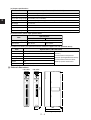
Sharp Programmable Controller
NEW
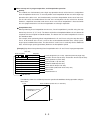
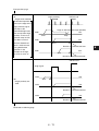
Satellite JW50H/70H/100H
Model name
JW-12PS
For four axes : JW-14PS
For two axes :
Pulse output module
,
User s Manual
JW-12
PS
JW-14
PS
Thank you for buying the pulse output module (JW-12PS/14PS) for the Sharp Programmable Controller JW50H/
70H/100H.
This manual describes how to install and use the JW-12PS/14PS.
Before you start to use the JW-12PS/14PS, be sure to thoroughly read this manual and fully understand its
features and functions to ensure correct use.
Be sure to store this manual in a safe place so that they can be easily retrieved whenever they are needed.
The following manuals are also provided for the JW-12PS/14PS and JW50H/70H/100H. Read these manuals
in addition to this manual.
JW-12PS/14PS
JW50H/70H/100H
Control module
User's Manual (this manual)
User's Manual (Hardware)
Programming Manual - Ladder Instructions
Request
• Every effort has been made in the preparation of this document. Should you have any questions or inquiries, please feel free to contact your dealer.
• Reproduction of this document in part or in whole is prohibited.
• The content of this document is subject to change without notice in the interest of product
improvement.
Safety Precautions
Read this user's manual and the attached documents carefully before installing, operating, or performing any
maintenance, in order to keep the machine working correctly. Make sure you understand all of the equipment
details, safety information, and cautions before using this machine. In this user's manual, the safety
precautions are divided into "Dangers" and "Cautions" as follows.
Danger
: Improper handling is likely to lead to death or serious injury.
Caution
: Improper handling may lead to injury or damage to equipment.
Caution is given, serious results may occur depending on the
Even when only a
circumstances. In all cases, important points are described. Be sure to follow the
advice given.
The following symbols are used to prohibit or explain required action.
: This means do not do what is described. For example, prohibited disassembly is shown as
: This means an action you must take. For example, a ground connection that must be made is
shown as
.
1. Installation
Caution
• Use only in the environments specified in the catalog, instruction manual, or user's manual.
Electric shock, fire or malfunction may result if used in high temperature, high humidity, dusty
or corrosive environments, or if excessive vibration or impact occurs.
• Install the equipment only as described in the manual.
An improper installation may cause the equipment to fail, breakdown, or malfunction.
• Never leave wire cuttings or any other foreign matter lying about.
A fire, breakdown or malfunction may result from inappropriate objects left near the
equipment.
2. Wiring
Compulsory
• Wiring should be performed by a qualified electrician.
Improper wiring may lead to a fire, machine failure or electric shock.
Caution
• Connect only to the specified power source.
Connection to the wrong power source may cause a fire.
3. Use
Danger
• Provide a safety fence around the facilities used for positioning.
• Assemble an external emergency stop circuit, interlock circuit or other means outside of the
pulse output module. Otherwise, a breakdown or damage to the other equipment may occur
due to a problem with the pulse output module.
• The motor may operate suddenly due to a deviation when the mains power supply is turned
OFF when power is being supplied to the encoder even if the mains power supply of the servo
driver (amplifier) is turned OFF. Accordingly, press the emergency stop button to reset the
error before turning the mains power supply, and then clear the error and deviation after the
mains power supply is turned ON.
Sefety - 1
.
Caution
• Take special care to follow all safety guidelines if you are changing the parameters for the
operating conditions or performing a "forced output," "run," or "stop" during operation.
Misoperation may damage the machine or cause an accident.
• Turn ON the power supplies in the specified sequence. Turning ON the supplies in the wrong
order may lead to a machine breakdown or cause an accident.
4. Maintenance
Prohibit
• Do not disassemble or modify the pulse output module.
Fires, breakdowns or malfunctions may occur, if the pulse output module is disassembled.
Caution
• Turn OFF the power source before connecting or disconnecting the pulse output module
Otherwise, electric shocks, malfunctions or breakdown may occur.
Sefety - 2
Precautions during Use
Pay attention to the following precautions during use of this module
(1) Installation site/storage
Avoid installing or storing the pulse output module in the following locations:
1. Location subject to the direct sunlight
2. Locations outside of the ambient operating temperature range of 0 to 55°C and storage range
of -20 to +70°C
3. Locations outside of the ambient relative humidity of 35 to 90%
4. Locations subject to sudden temperature changes that might cause condensation
5. Locations subject to corrosive gases or flammable gases
6. Locations subject to direct vibration or impact
(2) Installation
1. Before removing or attaching the rack panel, turn the PC OFF.
2. Firmly tighten the fastening screws of this module.
(3) Wiring
1. Avoid wiring input, output and power leads near to and in parallel with heavy-current lines and
power lines.
2. To prevent damage to machinery and accidents to personnel, assemble an external emergency
stop circuit, interlock circuit or other means outside of the pulse output module, and integrate a
stop output for the JW50H/70H/100H.
(4) Use
1. Before turning the switch ON and OFF, turn the PC OFF.
Otherwise, the pulse output module may malfunction.
2. On JW50H/70H/100H mounted with this module, be sure to set the I/O addresses of the control
module by optional I/O registration. (I/O addresses cannot be set by automatic I/O registration.)
(Reason) Though this module is the special I/O module for the JW50H/70H/100H, it differs from
regular special I/O modules in that 256 bytes of special I/O data registers area is
occupied.
3. Be sure to set the JW50H/70H/100H scan time to 2 ms or more. If the scan time is set to a lower
value, data sometimes cannot be transferred to this module.
(For details on setting the scan time, →see the JW50H/70H/100H Programming Manual.)
4. This module cannot be used (mounted) on the JW50H/70H/100H remote I/O slave module.
5. When the JW50H/70H/100H is turned OFF, the data on this module is overwritten. Accordingly,
after writing block data, be sure to save the new data to flash ROM (for backing up data) by the
block data save relay.
6. The housing of this module is provided with ventilation holes to prevent the inside of this module
from heating up. Do not block these ventilation holes or block the flow of air into and out from these
holes.
7. If you detect any malfunction or abnormality () with this module, immediately stop use, and contact
your dealer.
→See the figure on the following page.)
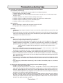
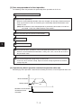
(5) Work safety during operation (→
• Provide a safety fence around robots.
• Provide a plug for entry/exit on the safety fence, and provide a structure so that robot operation
stops when the safety fence door is opened when a worker enters the area inside the safety fence.
• Provide a portable plug on the safety fence so that robot operation stops when that plug is extracted, and robot operation stays stopped even if a worker enters the area inside the safety fence
and closes the safety fence door still holding the plug.
• Provide a receptacle for on-site work for operating the robot inside the safety fence at the worker's
discretion. The robot operates by inserting the portable plug into this receptacle. When performing
teaching, for example, inside the safety fence to operate the robot, make sure that the worker is
outside of the robot's operation envelope.
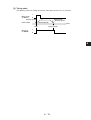
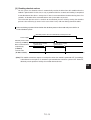
Precautions - 1
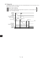
Plug for safety fence entrance
Entrance door
Receptacle for on-site work
Portable plug
(6) Static electricity
In abnormally dry locations, excessive amounts of static electricity may be generated on the human
body. To prevent adverse influence caused by static electricity, discharge any static electricity from
the human body before touching or handling this unit by touching a grounded metallic object.
(7) Cleaning
Use a soft, dry cloth to clean the pulse output module. Do not use volatile solvents (alcohol, paint
thinner, etc.) or wet rags to clean the module. Otherwise, the module may be deformed or discolored.
Precautions - 2
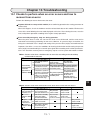
Chapter 1 Features, System Configuration and Basic Functions
Chapter 2 Specifications
Chapter 3 Names and Functions of Parts
Chapter 4 Installation and Connection
Chapter 5 Data Transfer
Chapter 6 Zero Return
Chapter 7 Direct Operation
Chapter 8 Program Operation
Chapter 9 Closed Loop Control
Chapter 10 Absolute System
Chapter 11 Other Functions
Chapter 12 Trial Operation
Chapter 13 Troubleshooting
Appendix
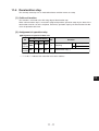
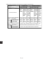
Contents
Chapter 1 Features, System Configuration and Basic Functions •••••••••••• 1-1 to 1-11
1-1 Features, basic system configuration 1-1
1-2 Basic functions and general outline 1-2
[1] Position control 1-2
[2] Speed control 1-3
[3] Other functions 1-4
1-3 Principle of operation of control systems, simple design of a positioning system 1-6
[1] Principle of operation of control systems 1-6
[2] Simple design of a positioning system (method of converting position and speed to pulse) 1-7
(1) Linear operation 1-7
(2) Rotary operation 1-9
1-4 Procedure up to start of operation 1-11
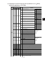
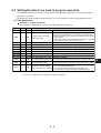
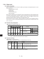
Chapter 2 Specifications •••••••••••••••••••••••••••••••••••••••••••••••••••••••••••••••••• 2-1 to 2-4
[1] General Specifications 2-1
[2] Functional specifications 2-2
[3] External dimensions 2-4
Chapter 3 Names and Functions of Parts •••••••••••••••••••••••••••••••••••••••••••• 3-1 to 3-4
[1] Display panel 3-2
(1) LED display 3-2
(2) Segment display (3 digits) 3-3
[2] Switches (MODE, INITIAL) 3-4
Chapter 4 Installation and Connection •••••••••••••••••••••••••••••••••••••••••••••••4-1 to 4-13
4-1 Installing this module 4-1
4-2 Connecting connectors to this module 4-2
[1] Connecting the CN1 connector for tool connection 4-2
[2] Connection of connectors CN2/CN3 for axes 4-4
4-3 Connecting (wiring) to external devices 4-6
[1] Wiring in open loop control with a general pulse driver 4-7
[2] Wiring in closed loop control with a general pulse driver 4-8
[3] Wiring in closed loop control with a general pulse driver 4-9
[4] Wiring in open loop control with a general servo driver 4-10
[5] Wiring of the input section 4-11
[6] Wiring of CW/CCW pulse output signals 4-12
[7] Wiring of clear deviation output/general-purpose output signals 4-12
[8] Wiring of origin signal 4-13
CONTENTS - 1
Chapter 5 Data Transfer ••••••••••••••••••••••••••••••••••••••••••••••••••••••••••••••••••5-1 to 5-63
5-1 Data transfer between this module and the JW50H/70H/100H control module 5-1
[1] Refresh area 5-1
[2] Block data 5-4
5-2 Operation data area 5-10
[1] Assignment of special I/O data area 5-10
(1) Input section (N+0000 to 0177) 5-10
(2) Output section (N+0200 to 0377) 5-11
[2] Description of functions 5-12
(1) Input section (PC←PS) 5-12
(2) Output section (PC→PS) 5-14
5-3 Parameters 5-18
[1] Parameter assignments 5-18
(1) Parameter 1 (regular parameters: must be set independently on each axis) 5-18
(2) Parameter 2 (special parameters: must be set independently on each axis) 5-19
[2] Parameter setup procedure 5-20
[3] Details of parameters 1/2 5-21
(1) Details of parameter 1 5-21
(2) Details of parameter 2 5-25
5-4 How to transfer to the relay area 5-26
[1] Special I/O data area assignments 5-28
5-5 How to block-transfer any single block of data 5-33
5-6 Data read/write ladders in block transfer 5-37
[1] Outline 5-37
[2] BD.REQ signal 5-39
5-7 Sample ladder program for batch transfer of all axes and all block data 5-40
5-8 Transfer of any X-axis block when top address of special I/O area is set to 49000 5-46
5-9 Ladder programs for block transfer of any block of data and transfer of all block data 5-50
[1] Assignment of special I/O data area when top address is set to 1000
by optional I/O registration on JW-14PS
5-51
[2] Sample ladder program 4 5-53
[3] Sample ladder 5 5-54
5-10 Transfer of any X-axis block when top address of special I/O area is set to 1000 5-60
Chapter 6 Zero Return ••••••••••••••••••••••••••••••••••••••••••••••••••••••••••••••••••••6-1 to 6-19
6-1 Zero return operation 6-1
6-2 Example of operation by origin detection method 6-3
6-3 Operation patterns by origin detection method 6-6
[1] Limit end inversion ON (inversion mode 1) 6-6
[2] Limit end inversion OFF (Inversion mode 2) 6-9
[3] All inversion OFF 6-12
6-4 Zero return timing chart 6-15
[1] When there is no origin compensation data 6-15
[2] When there is origin compensation data 6-16
[3] Immediate stop of zero return 6-17
6-5 Move origin 6-18
[1] Assignment of operation relay area and setting of operation data area 6-18
[2] Timing chart 6-19
CONTENTS - 2
Chapter 7 Direct operation •••••••••••••••••••••••••••••••••••••••••••••••••••••••••••••• 7-1 to 7-11
7-1 Explanation of direct operation 7-1
[1] Outline 7-1
[2] Startup of direct operation 7-1
[3] Data setup procedure in direct operation 7-2
[4] Operation by direct operation matched to operation data area 7-3
7-2 Setting data to be used for direct operation 7-3
[1] Axis parameters 7-3
[2] Operation relay 7-3
7-3 Basic operation of direct operation 7-4
[1] Position control operation 7-4
[2] Speed control operation 7-5
7-4 Nested startups in direct operation 7-6
7-5 Direct operation sample program 7-8
Chapter 8 Program Operation ••••••••••••••••••••••••••••••••••••••••••••••••••••••••••8-1 to 8-19
8-1 Outline 8-1
[1] Axis designation 8-2
[2] Axis designation and flags 8-3
8-2 Setting the data to be used in program operation 8-5
[1] Axis parameters 8-5
[2] Operation relay 8-6
8-3 Operation in program operation 8-7
[1] Startup of program operation 8-7
[2] Operation in program operation according to step data 8-7
[3] Linear interpolation 8-10
8-4 Data setup procedure in program operation 8-11
8-5 Timing chart in program operation 8-12
[1] Busy flag 8-12
[2] Step No. enable 8-12
[3] Timing chart of startup by single-step operation 8-13
[4] Startup timing chart 8-14
8-6 Example of program 8-15
[1] Step data when performing program operation on X-axis 8-16
[2] Step data when performing program operation on Y-axis 8-18
Chapter 9 Closed Loop Control ••••••••••••••••••••••••••••••••••••••••••••••••••••••••• 9-1 to 9-9
9-1 Setting items required in closed loop control 9-1
9-2 Description of operation in operation modes 9-1
[1] Mode 0 9-1
[2] Mode 1 9-2
[3] Mode 2 9-3
9-3 Table of setting values and operations 9-4
9-4 Mode setup methods 9-5
[1] Mode 0 9-5
[2] Mode 1 9-5
[3] Mode 2 9-6
CONTENTS - 3
9-5 Electronic gear setup methods and restrictions 9-7
[1] Restriction 1 when setting up the electronic gear 9-7
[2] Restriction 2 when setting up the electronic gear 9-8
[3] Details of electronic gear 9-8
Chapter 10 Absolute System •••••••••••••••••••••••••••••••••••••••••••••••••••••••••• 10-1 to 10-6
[1] Parameters and operation data relating to absolute system 10-1
[2] Driver and motor that can configure an absolute system 10-1
[3] Absolute system setup procedure 10-2
[4] Reading absolute values 10-5
[5] Matching the mechanical origin on an absolute system 10-6
Chapter 11 Other Functions •••••••••••••••••••••••••••••••••••••••••••••••••••••••••• 11-1 to 11-24
11-1 Jog operation 11-1
[1] Outline of function 11-1
[2] Jog operation execution procedure 11-1
[3] Assignment of operation relay and operation data settings 11-1
[4] Timing chart 11-2
[5] 1-second wait operation (inching) 11-2
11-2 Teaching 11-3
[1] Outline of teaching function 11-3
[2] Teaching execution procedure 11-3
[3] Assignment of operation relay and operation data settings 11-4
[4] Timing chart 11-4
11-3 Interrupt jog feed 11-5
[1] Outline of function 11-5
[2] Startup from program operation 11-5
[3] Startup by direct operation 11-7
[4] Speed control operation 11-7
[5] Assignment of operation parameter and operation I/O data setting 11-8
11-4 Forced intervention startup 11-9
[1] Outline of function 11-9
[2] Procedure for use of forced intervention operation 11-9
[3] Assignment of operation relay 11-9
[4] Timing chart 11-10
11-5 Deceleration stop 11-11
[1] Outline of function 11-11
[2] Assignment of operation relay 11-11
[3] Deceleration stop during positioning 11-12
[4] Timing chart 11-14
11-6 Change present position 11-15
[1] Outline of function 11-15
[2] Assignment of operation relay and operation data setting 11-15
[3] Timing chart 11-15
11-7 Override 11-16
[1] Outline of function 11-16
[2] Assignment of operation relay and operating data setting 11-16
[3] Timing chart 11-17
CONTENTS - 4
11-8 Clear error 11-18
[1] Outline of function 11-18
[2] Operation relay assignment 11-18
[3] Parameter settings 11-18
[4] Timing chart 11-19
11-9 Clear deviation output 11-20
11-10 Backlash compensation 11-21
[1] Outline of function 11-21
[2] Axis parameter settings 11-21
[3] Backlash compensation operation 11-21
[4] Backlash compensation at linear interpolation 11-22
11-11 General-purpose input 11-23
11-12 General-purpose output 11-24
Chapter 12 Trial Operation••••••••••••••••••••••••••••••••••••••••••••••••••••••••••• 12-1 and 12-2
Chapter 13 Troubleshooting •••••••••••••••••••••••••••••••••••••••••••••••••••••••• 13-1 to 13-10
13-1 Checks to perform when an error occurs and how to recover from an error 13-1
13-2 Cautions in system configuration with servo driver 13-3
13-3 Error tables 13-5
Appendix •••••••••••••••••••••••••••••••••••••••••••••••••••••••••••••••••••••••••••••••••••• A-1 to A-28
Appendix 1 Setting the sinusoidal acceleration/deceleration speed A-1
Appendix 2 Way of thinking behind interpolation and maximum speed of each axis A-2
Appendix 3 Way of thinking behind acceleration/acceleration time A-3
Appendix 4 Ladder programming of various operations A-4
Appendix 5 Table of block data for each axis applied to file 1 with sample ladder program used A-9
[1] For X-axis A-9
[2] For Y-axis A-14
[3] For Z-axis A-19
[4] For A-axis A-24
CONTENTS - 5
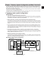
Chapter 1 Features, System Configuration and Basic Functions
The JW-12PS/14PS (simply called "this module" from here on) is the pulse output module for the
programmable controller (simply called "PLC" from here on) JW50H/70H/100H. (The JW-12PS is for two
axes, while the JW-14PS is for four axes.)
The pulse train is output to a stepping motor driver or servo motor driver by instructions from the JW50H/
70H/100H to achieve various positioning control.
As position signals are loaded directly from an encoder, closed loop control can be achieved even though
the output type is pulse train, thus configuring a more reliable system.
1-1 Features, basic system configuration
Main features
1. Sinusoidal acceleration/deceleration characteristics
Multi-stage sinusoidal acceleration/deceleration can be selected. This achieves acceleration/
deceleration characteristics matched to the positioning target, suppresses overshooting and
undershooting, and enabled smooth, high-speed operation.
2. Signals input from an encoder can be captured and used in closed loop control.
This module has integrated encoder input, which enables a closed loop to be configured for loading
position signals from the operation system. Position data from the instruction system can be compared
with position data from the operation system to perform compensation, thus building a highly reliable
system.
3. Various operation data from the dedicated support software that runs on Windows 95/98 can be set.
Various operation data can be set and edited on a third-party personal computer (Windows 95/98). This
data can be written to this module, and data on this module can be read, saved and output. (scheduled
to be supported in the near future)
4. Integrated general-purpose inputs (1 input/axis), general-purpose outputs (1 output/axis)
This module is provided with an integrated general-purpose input (1/axis) and an general-purpose
output (1/output) that allow direct I/O. This achieves high-speed response in interrupt startups and
interrupt outputs that do not pass via the PLC.
5. Absolute positioning systems (absolute systems)
Communications with absolute-compatible servo drivers, thus enabling systems that do not require
zero return at a power interruption to be configured. (Consult your dealer for details of servo drivers and
motors that are compatible with absolute systems.)
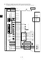
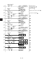
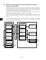
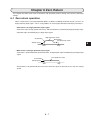
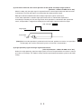
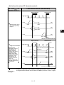
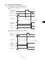
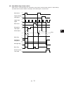
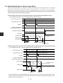
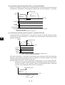
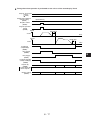
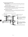
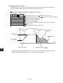
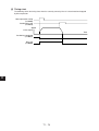
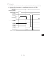
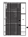
Example of basic system configuration
JW50H/70H/100H
Control module
Data memory
I/O refresh
Program
This module
(JW-12PS/14PS)
Operation
Pulse
instructions,
instructions
operating
Completion
status
signals
Operation
data
Encoder input
(RAM)
(closed loop control)
Encoder input (closed loop control)
Deviation
counter
D/A
conversion
M
Interface
(F/V)
Feedback pulse
Operation
data
Servo
amplifier
Servo motor
PG
Operation
data
(FROM)
RS-422A
Absolute data request command instruction
PC
• In the case of an absolute-compatible driver (manufacturer limited)
Wind 95/98 dedicated
software
Editing/saving/printing,
etc. of various operation
data
(scheduled to be supported in the near future)
1-1
1
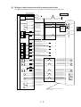
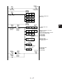
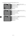
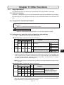
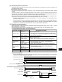
1-2 Basic functions and general outline
The following shows the basic functions of this module.
1
JW-12PS/14PS functions
Position
control
[1]
Program operation
Single-step positioning
Automatic positioning
Continuous positioning
Direct operation
Interrupt jog feed
Speed control [2]
Other functions
[3]
Zero return
Jog operation
Teaching
Override
Change current position
Backlash compensation
M output
Deceleration stop
Move origin
[1] Position control
Two types of travel, absolute travel and relative travel are possible. With absolute travel (positioning by
absolute values), positioning is performed by absolute values from the origin, and with relative travel
(positioning by incremental values), positioning is performed by incremental values fro the present
position.
There are two positioning modes "program operation" and "direct operation."
"Interrupt jog feed" by which operation is stopped after travel by a specified travel distance is also
possible by the interrupt input signal.
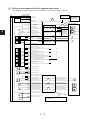
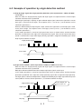
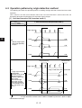
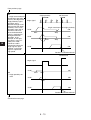
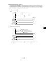
(1) Program operation
With program operation, data (simply called "step data" from here on) such as position and speed
data is transferred beforehand to this module, and positioning is performed by specifying the No. of
that step data from PC.
Up to 99 steps for a single axis can be set as the step data.
Step data is executed in sequence from the specified step data No.
Note, however, that execution of step data jumps to a jump destination if a jump is programmed.
Executed in sequence
Step data No.99
Step data No.0
Acceleration
time data No.
Startup speed
data No.
Startup
Target speed
data No. Deceleration
time data No.
Position
Position
Target
position
Positioning control (Positioning by linear interpolation and on two independent axes is possible.)
Speed
Time
1-2
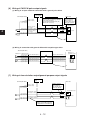
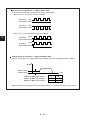
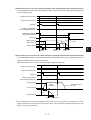
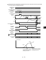
There are three positioning control modes "single-step positioning," "automatic positioning" and
"continuous positioning" depending on the end pattern to be set to the step data.
• Single-step positioning
• Automatic positioning
Pulse output
Pulse output
Step data
No.0
Startup
• Continuous positioning
Step data
No.0
Step data
No.1
Step data
No.0
Step data
No.1
Time
Step data
No.1
Time
Startup
1
Pulse output
Startup
Time
Startup
Stops after time
preset to dwell
timer has elapsed.
No stop
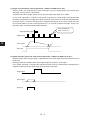
(2) Direct operation
With direction operation, positioning is performing by directly setting position data (or position No.)
and speed data (or speed No.) from the PLC to an area assigned on the PLC's data memory.
(3) Interrupt jog feed
The axes move by the specified travel and come to a stop when the interrupt input signal is entered.
Pulse output
Interrupt input
Interrupt travel
distance
Time
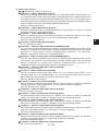
[2] Speed control
With speed control, the pualse is output continuously by a single startup, and the speed can be changed
any number of times during operation.
Speed change instruction
(override)
↑
Speed change
Speed instruction
(override)
↑
Time
To stop operation, use the deceleration stop instruction of the interrupt jog feed instruction.
Deceleration stop instruction
Interrupt jog feed instruction
↑
Speed
↑
Speed
Time
Time
Both program operation and direct operation is possible in speed control.
1-3
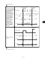
[3] Other functions
(2) Jog operation
This function is the operation of starting up and stopping travel on a specified axis at a specified
speed.
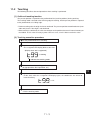
(3) Teaching
This function is the operation of loading the present position to specified position data.
Origin Present position
↑
1
(1) Zero return
This function determines the origin of a specified axis.
CCW
CW
Specified position data No.
(4) Override function
This function changes the target speed to a speed obtained by applying an override according to the
override enable instruction during positioning.
Pulse output
A×1.5
Override setting value : 150%
A
Time
Override 1
Enable 0
(5) Change present position
This function changes the present position to specified data according to the present position preset
instruction.
(6) Backlash compensation
This function compensates for error that occurs in gear meshing in mechanical systems.
(7) M output
This function turns the M output flag when the present position is within a specified range.
CCW
CW
M output setting
M output flag
ON
OFF
1-4
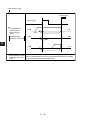
(8) Deceleration stop
This function causes operation to decelerate and come to a stop according to the deceleration stop
instruction.
1
Deceleration stop
Pulse output
Time
(9) Move origin
This function returns the axes to a preset origin.
• This function is enabled only when the origin has been confirmed.
1-5
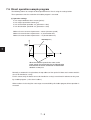
1-3 Principle of operation of control systems, simple design of a positioning system
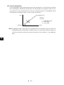
[1] Principle of operation of control systems
This module adopts a pulse output type open loop control system. "Open loop control" is a system
where control is performed without positional feedback on the assumption that the motor operates
according to given input pulses. Stepping motors are often used in this control system. Stepping
motors rotate for the predetermined angle each time that a pulse signal is given. Accordingly, the rpm
of stepping motors is proportional to the number of pulses of the pulse train from this module, and the
rotation speed is proportional to the frequency of the pulse train.
Angle of rotation
1
Position output
12
n
Position instruction pulse
• When open loop control is used on this module, all speed data (p/s) and coordinate data (p) are
set referenced to pulses.
1-6
[2] Simple design of a positioning system (method of converting position and speed to pulse)
(1) Linear operation
The following describes linear operation by positioning such as below a stepping motor.
1
Gear A
Gear B
V
N
m
Stepping motor
Reduction gear ratio
Table
P
Feed screw pitch
: Angle of rotation per pulse (angle/pulse -> deg/p)
: Rotary pulse coefficient, number of pulses per rotation (number of pulses/single motor rotation → p/rotation)
m : Reduction gear ratio → number of teeth of gear A/number of teeth of gear B)
: Pulse rate coefficient (travel distance per pulse)
P : Feed screw pitch (travel distance/rpm → mm/rotation)
v : Table travel speed (travel distance/sec → mm/s)
VP : Set pulse speed (speed to set to this module, number of pulses/sec → p/s)
L : Set travel distance (mm)
PL : Number of set travel pulses
Formula for calculating the pulse rate
First, the rotation pulse coefficient . (number of pulses per single rotation)
=360° / (p/rotation) is calculated:
Thus, the pulse rate coefficient becomes:
=P/( ×m)=(P× ) / (360×m) (mm/P)
Next, the pulse speed VP (speed to set to this module) when the table travel speed v is generated
from this coefficient:
VP=v/ =v×(360×m)/(P×v) (p/s)
The number of pulses (PL) for arriving at the set travel distance is calculated as follows:
PL=L/ =L×(360×m)/(P× ) (p)
1-7
Example
1
The data to set to this module is as follows when positioning is performed at a set speed of 5000
(mm/s) and set coordinates 20000 (mm).
<Conditions>
500 pulses are required for a single rotation of the motor.
The number of teeth of gear A is 50, and the number of teeth of gear B is 100.
The feed screw pitch is 10 (mm/rotation).
The following value is calculated from the above conditions:
m=100/50=2
=500
P=10
v=5000
L=20000
First, calculate the pulse rate coefficient.
=P/( ×m)=10/1000=0.01
Accordingly, the pulse speed to set to this module becomes:
VP=v/ =5000/0.01=500000(p/s)
And, the pulse travel distance to set to this module becomes:
PL=L/ =20000/0.01=2000000(p)
1-8
(2) Rotary operation
The following describes rotary operation by positioning such as below a stepping motor.
Stepping motor
Gear A
1
Shaft
Gear B
Vr
: Angle of rotation per pulse (angle/pulse → deg/p)
: Rotary pulse coefficient, number of pulses per rotation (number of pulses/single motor rotation → p/rotation)
: Rotation pulse rate coefficient (number of pulses/single rotation of shaft → p/rotation)
m : Reduction gear ratio → number of teeth of gear A/number of teeth of gear B)
Vr : Shaft rotation speed (number of rotations/sec → rps)
Vp : Set pulse speed (speed to set to this module, number of pulses/sec → p/s)
R : Shaft rpm (rpm)
PL : Number of set travel pulses
The rotary pulse coefficient is calculated:
=360/ (number of pulses/rpm → p/rotation)
Thus, the pulse rate coefficient becomes:
= m=360×m/
(p/rotation)
Next, the pulse speed VP (speed to set to this module) when the table travel speed Vr (rps) is
generated from this coefficient:
VP=Vr =Vr×360×m/ (p/s)
The number of pulses (PL) for arriving at the set rpm is calculated as follows:
PL=R× =R×(360×m/ ) (p)
1-9
Example
1
The data to set to this module is as follows when rotation is performed at a shaft rotary speed of 20
(rps) and number of shaft rotations of 100.
<Conditions>
2 pulses are required for a 1° (deg) rotation of the motor.
The number of teeth of gear A is 50, and the number of teeth of gear B is 200.
The following value is calculated from the above conditions:
First, calculate the pulse rate coefficient.
m=200/50=4
=1/2=0.5
=360/0.5=720(p/rotation)
The rotary pulse rate coefficient is calculated from these values as follows:
=720×4=2880(p/rotation)
Accordingly, the pulse speed to set to this module becomes:
VP=Vr =20×2880=57600(p/s)
And, the pulse travel distance to set to this module becomes:
PL=R =100×2880=2880000(p)
• When the value of PL exceeds 9999999, perform speed control. In this case, the rotation
speed cannot be managed.
1 - 10
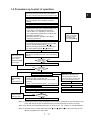
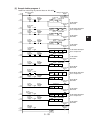
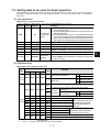
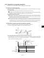
1-4 Procedure up to start of operation
Wiring of external inputs (⇒See Chapter 4.)
• Wire origin input signal, origin proximity input, CW/CCW
limit input, emergency stop input, and general-purpose input.
1
Wiring of motor and driver
• Wire according to motor and driver Instruction
Manual.
Wiring of driver and this module (⇒See Chapter 4.)
Setting of axis block data
• Set parameters (I/O states, operation mode, zero
return mode, acceleration/deceleration data,
software limits, etc.) required for control of this
unit, and positioning related data (coordinate data,
speed data, step data, etc.)
• With direct operation, operation is possible by
setting only parameters.
When an error
occurs, correct the
erroneous section
according to the
error code. (Note 2)
Block transfer
• Perform block transfer using block transfer ladder
program (sample ladder program or ).
• When transferring only parameters, directly write
by sample ladder program
or . (Note 3)
If busy state cannot
be canceled after
several retries,
initialize flash ROM
and set again.
Clear error
• The error is cleared by the clear error relay turning
ON (↑).
ON
Error flag
OFF
Saving of block data (transfer to flash ROM)
ON
Busy flag
OFF
When performing direct operation
Other functions
(jog, teaching,
etc.)
→See Chapter 11.
Correct data and
ladder program,
and reset error.
When performing program operation:
(Note) When operating for first
time after wiring, perform trial
operation by direct operation, and
then perform program operation.
Setting of operation data area
• Set position data, speed data, and
acceleration/deceleration time No. (Set in ladder
program.)
• Create a startup ladder program. (⇒See page 125.)
Preparation of ladder program for startup
Zero return (Note 1)
Zero return (Note 1)
Trial operation, debugging (partially duplicates above flow, Note 2)
Operation
NG
Trial operation (Note 2)
OK
Operation
(Note 1) Regarding functions that do not operation unless origin is confirmed, be sure to perform a zero
return and change the present position before executing operation to confirm the origin.
(Note 2) For details on the operation flow when an error occurs, see "Chapter 13 Troubleshooting."
(Note 3) Selection of the sample ladder program (
address by optional I/O registration.
1 - 11
and
,
and
) is determined by the top
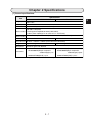
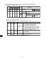
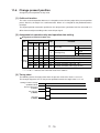
Chapter 2 Specifications
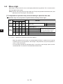
[1] General specifications
Specifications
Item
JW-12PS
JW-14PS
Storage temperature -20 to 70°C
Ambient temperature 0 to 55°C
Ambient humidity 35 to 90%RH (condensation not allowed)
JIS C0911 compliant
Vibration resistance • Peak-to-peak amplitude 0.15mm(10 to 58Hz),
9.8m/s2(58 to 150Hz)(2 hrs on each of X, Y and Z axes)
2
Vibration resistance JIS C0912 compliant 147m/s (3 times on each of X, Y and Z axes)
Power consumption (5 VDC) Max.450mA *
Max.550mA *
External dimensions 33.5mm × 250mm × 105mm(w/out connector connection)
Approx. 550 g
Weight
Approx. 500 g
Atmosphere
Corrosive gases not allowed
Accessories
• 50-pin connector (for shaft connection) • 50-pin connector (for shaft connection)
10150-3000VE(50-pin receptacle
10150-3000VE(50-pin receptacle
soldered type)1 p'ce
soldered type)2 p'ces
10350-52F0-008(shell) 1 p'ce
10350-52F0-008(shell) 2 p'ces
*Supplied from JW50H/70H/100H rack panel
2-1
2
[2] Functional specifications
(1) Performance specifications
Item
Applicable PLC
Specifications (JW-12PS/14PS)
JW50H/70H/100H Series
Number of occupied I/Os I/O relays: 2 bytes, data registers: 256 bytes (special I/O area)
2
Control target driver Pulse train input servo driver or driver for stepping motor
Control method
Open or closed loop control based on pulse train output
Number of controlled axes JW-12PS:2 axes(X,Y),JW-14PS:4 axes(X,Y,Z,A)
Control unit
Pulse
Control modes
Single-step operation, linear interpolation operation, speed control, interrupt jog feed (speed->position control)
Operation modes
Zero return, jog operation, direct positioning operation, program positioning operation.
Pulse output
System
CW, CCW format or signed pulse system
Signal
Open collector output or line driver output
System
Absolute value or relative value instruction
Position instructions Data
-9999999 to 9999999 Pulse
Number of data items 99/axis (number of data items in program operation *unlimited in direct operation)
Data
1 to 500 kpps *1 to 250 kpps when the pulse output signal format is open collector
Speed instructions Speed resolution 4
Number of data items 64/axis (number of data items in program operation *unlimited in direct operation)
Acceleration/
deceleration
instructions
System
Ramp or sinusoidal (sinusoidal coefficient of 0 to 99% set to each axis)
Data
1 to 250000 ms
Number of data items 9/axis
Number of steps 99 steps/axis (position, speed and acceleration/deceleration data same as above)
Instructions for
program operation Operation pattern Single-step, automatic, continuous, continuous control, interrupt jog feed
Dwell timer
Each axis settable to 0 to 9.99 sec. (in 10-ms increments) (16 patterns settable to each axis)
Origin proximity input signal: OFF, a contact, b contact
Origin input signal: b contact, a contact
Origin compensation data: -9999999 to +9999999 pulse
Zero return
Jog operation
Teaching
6 basic zero return operation modes
Stop by origin input signal after escape from origin proximity
Origin proximity edge detection 1 (count method 1, origin input signal used)
Origin proximity edge detection 2 (count method 2, origin input signal not used)
Origin proximity signal not used
Inversion at limit end, zero return operation at low speed, and stop at origin
Origin proximity signal and origin signal both unused
Possible by instructions from PLC or instructions from personal computer (running dedicated software)
Present position registered to specified No. data by instruction from PLC
Present position registered to specified No. data by instruction from personal computer (running dedicated software)
Deceleration stop
Deceleration stop according to deceleration time by deceleration stop instruction
Emergency stop
Pulse output immediately stopped by external emergency stop signal
Change present position Present position changed to preset value by present value position preset instruction
Override
Speed is changed to speed obtained by applying override coefficient to target speed by
override instruction during operation (settable within range 0 to 999%)
Backlash compensation 0 to 9999 Pulse
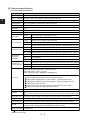
Continued on next page
2-2
From previous page
Item
Software limit
Specifications (JW-12PS/14PS)
Settable within range -9999999 to +9999999 pulses
Auxiliary output (M output) 8 outputs/axis (output to external relay)
General-purpose input 1 input/axis, real-time external input not via PLC (used for interrupt jog feed, etc.)
General-purpose output 1 input/axis, real-time external input not via PLC (used for interrupt output)
Setting method for
operation data
Set by ladder program on PLC
Set from personal computer (dedicated software required, scheduled to be supported in the near future)
Backed up by internal flash ROM on this module
Saving of operation * Data can be saved to hard disk or other storage media on personal computer by dedicated
software running on personal computer.
data
(Dedicated software is scheduled to be supported in the near future.)
(2) Pulse output specifications
Specifications (JW-12PS/14PS)
Item
Signal names
CW, CCW (open collector output)
Output system
NPN transistor (sync output)
Rated output voltage
5/12/24VDC
Output voltage range
4.75 to 26.4VDC
Output current
Max. 30 mA
On voltage
1 V or less
OFF leak current
0.2 mA or less
Pulse output start time
8 ms or less
* Time from acceptance of PLC startup signal up to output of pulse
Differential output
(AM26LS31 or equivalent, RS-422A
compliant)
Max. output pulse frequency 250 kpps
Breakdown voltage
CW, CCW (line driver output)
500 kpps
500 VAC (across external input terminal and secondary circuit) *photocoupler insulation
(3) Input specifications
Item
Signal name
Specifications (JW-12PS/14PS)
Driver error, positioning completed, origin Encoder A/B/Z phase input (line driver
proximity, origin (24 V), upper limit, lower output and 5V open collector output
limit, general-purpose input, emergency stop supported)
Rated input voltage (range) 24VDC (21.4 to 26.4VDC)
5VDC (3 to 5.5VDC)
Rated input current
5.8mA (24V) <12mA (24V)> *
20mA (5V)
Input ON level
20 V/5 mA or less (20 V/12 mA or less)*
3V/ 12 mA or less
Input OFF level
6 V/1.5 mA or less (6 V/2 mA or less)*
1 V/ 2 mA or more
Input response time
1 ms or less (ON→OFF, OFF→ON)
4X, 500 kpps
Breakdown voltage
500 VAC (across external input terminal and secondary circuit) *photocoupler insulation
* Figures in parentheses "()" are for origin (24 V) only.
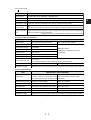
2-3
2
(4) Output specifications
Item
Specifications (JW-12PS/14PS)
Signal names
Clear deviation/general-purpose output
Output type
NPN transistor output (sync output)
Rated output voltage (range) 5/12/24VDC (4.75 to 26.4VDC)
Output current
Max. 30 mA (integrated surge protection for general-purpose output)
ON voltage
1.5 V or less
OFF leak current
0.2 mA or less
Output response time
1 ms or less (ON→OFF, OFF→ON)
Breakdown voltage
500 VAC (across external input terminal and secondary circuit) *photocoupler insulation
(5) External 24 V power input specifications
Specifications
Item
JW-12PS
JW-14PS
Rated input voltage (range) 24VDC (21.6 to 26.4VDC)
Input current
Max. 80 mA
Max. 150 mA
(6) Communications port (communications between support tool and specified driver)
Item
Specifications (JW-12PS/14PS)
Communications standard RS-422A (1:N communications allowed)
(Remarks)
Transmission speed 38400bps
• Communications with personal
computer (running dedicated software)
Data length
8 bits
Parity bit
None
Stop bit
1 bit
Connector
Half 14-pin (receptacle side on this module)
• Communications with servo driver
made by specific manufacturer
[3] External dimensions
• JW-14PS
JW-14PS
X
Y
Z
A
JW-12PS
X
Y
CW
CCW
READY
FAULT
87
MODE
32
INITIAL
CN1
CN1
CN2(X,Y)
CN2(X,Y)
250
INITIAL
654
32
1 09
MODE
1 09
654
CW
CCW
READY
FAULT
• JW-12PS
87
2
CN3(Z,A)
S1.0
S1.0
33.5
105
110
(including rack panel)
2-4
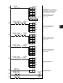
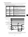
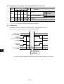
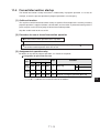
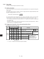
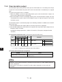
Chapter 3 Names and Functions of Parts
JW-12PS
JW-14PS
3
Function
Name
Display panel
Displays the point No., axis operating state and other information using
the segment LED (three digits) and indicators (X, Y, CW, CCW, etc.).
MODE switch
Sets the operation mode.
INITIAL switch
Initial switch
Connection for tool
connector (CN1)
For details, →see page 3-4.
This connector is for connecting to a Windows machine
(OS: Windows 95/98).
• An exclusive cable and communications adapter (JW-100SA) are
used for the connection.
This connector is for the communications with a driver in an absolute
system.
Connector for X-/Y-axes
(CN2)
This connector is for connecting to the servo driver for the X-/Y-axes.
• The module side connector of the connector cable is provided with
this module.
Connector for Z-/A-axes
(CN3: JW-14PS only)
This connector is for connecting to the servo driver for the Z-/A-axes.
• The module side connector of the connector cable is provided with
this module.
3-1
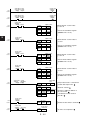
[1] Display panel
The operation status of this module is indicated by the state (lit, out, blinking) of LEDs on the display
panel.
JW-12PS
JW-14PS
JW-12PS
JW-14PS
Segment display (red)
→See the following page.
X
Y
3
CW
CCW
READY
FAULT
X
Y
Z
A
CW
CCW
READY
FAULT
LED display area
(red)
(1) LED display
LED Name
Description
X
Operation state of X-axis
• At normal operation: lit, During a stop: out, During an error: blinking
Y
Operation state of Y-axis
• At normal operation: lit, During a stop: out, During an error: blinking
Z
Operation state of Z-axis
(JW-14PS only) • At normal operation: lit, During a stop: out, During an error: blinking
A
Operation state of A-axis
(JW-14PS only) • At normal operation: lit, During a stop: out, During an error: blinking
CW
CCW
Lit at CW pulse output of axis (*)
Lit at CCW pulse output of axis (*)
READY
Ready signal
• Lit when parameters, etc. are normally set and the unit is ready for operation
FAULT
Error state
• Blinking when an error occurs (Error code is displayed on segment LED.)
• Lit when a watchdog timer error occurs (CPU runaway, etc.)
* The axis turned on by "X, Y, Z, A" of a lamp
3-2
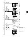
(2) Segment display (3 digits)
The data No., error code, etc. are indicated in each operation mode.
Segment display: 3-digit display (0 to 9, -, P, d, F, J, t, H, h)
3rd digit 2nd digit 1st digit
The following table shows the main content that is displayed.
State
Regular
operation
mode
During teaching
Description on segment display
Normal
Error
Position data No, step data No., etc.
Error No., etc.
• FAULT indicator blinks.
Position data No., etc.
• When the position data No. is selected, the segment display does not blink.
The segment display is lit after teaching is executed.
In system maintenance mode System information (version information, etc.)
The following describes the indication of the 3rd digit.
• Program operation "execution in progress" indication
• Lower two digits are step No.
• Direct operation "execution in progress" indication
• During block data save (transfer to flash ROM)
• Jog operation "execution in progress" indication
• Indication during teaching or at end of teaching
• Lower two digits are teaching No. Blinks during
teaching, and is lit at end of teaching.
• During teaching, other indications for that axis are
not output. However, priority is given to other axis if
execution of other axis is started during teaching.
• Zero return "execution in progress" indication
• Move origin indication
Indication of the CW and CCW LEDs is interlocked with the above indications.
3-3
3
[2] Switches (MODE, INITIAL)
Name
Type
Description of functions
Sets the operation mode:
0: Regular operation mode (startup axis enable display mode) *1
1: Regular operation mode (X-axis enable display mode)
2: Regular operation mode (Y-axis enable display mode)
3
MODE
Rotary
switch
0 to 9
(4 bits)
3: Regular operation mode (Z-axis enable display mode)
4: Regular operation mode (A-axis enable display mode)
5: - (unused)
6: - (unused)
7: - (unused)
8: System maintenance mode (system version upgrade, etc.)
9: Setting prohibited
INITIAL
Push
switch
The INITIAL switch has the following two functions:
For initial start (same as restart by power ON
When the MODE switch is set to 0 to 4, and the INITIAL switch is
held down for at least 5 seconds, the data recorded to flash ROM
is read to RAM area (*2).
For initialization
When the MODE switch is set to 8, and the INITIAL switch is held
down for at least 5 seconds, RAM area is initialized (set to the
default or factory setting state).
*1 The latest startup data is indicated for the display when "10" is set.
[Example] When direct operation is applied on the Y-axis during program
operation on the X-axis, the information of the Y-axis is displayed.
Note, however, that the information of the first axis to be started up is not
indicated even during operation if the axis that started up later has stopped.
*2 Memory that is used during actual operation
3-4
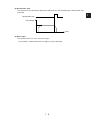
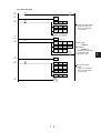
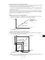
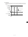
Chapter 4 Installation and Connection
4-1 Installing this module
This module is installed on the I/O slots of the rack panel (JW-6BU/13BU, etc.) for the JW50H/70H/
100H. It is not installed on the option slots.
Turn the JW50H/70H/100H OFF.
Insert the connector for this module into the module connector on the rack panel, and tighten
the module fixing screws at the top and the bottom with the Phillips screwdriver.
Module retention screw
Module connector
Rack panel
Rack panel
Phillips screwdriver
This module (JW-12PS/14PS)
This module (JW-12PS/14PS)
• Two or more of these modules can be mounted in any of the I/O slots.
Cautions
• Firmly tighten the module retention screws. Loose screws may result in malfunction.
• Do not block the ventilation holes on this module or block the flow of air into and out from these
holes. Doing so might cause the temperature inside the module to heat up and cause
malfunction.
4-1
4
4-2 Connecting connectors to this module
The following describes how to connect the CN1 connector for tool connection, CN2 connector for X-/
Y-axes and CN3 for Z-/A-axes (JW-14PS only).
[1] Connecting the CN1 connector for tool connection
Connect this connector to the third-party personal computer (Windows 95/98). Use the dedicated cable
and communications adapter (JW-100SA, sold separately) for connection.
Personal computer
(DOS/V)
This module
(JW-12PS/14PS)
*Exclusive cable (2 m or less)
JW-14PS
X
Y
Z
A
(9-pin connector)
765
432
MODE
98
80 mm
10
4
CW
CCW
READY
FAULT
INITIAL
CN1
140 mm
CN2(X,Y)
Plug
Connector
(D-Sub 25-pin) (14-pin)
CN3(Z,A)
JW-100SA
(Communications adapter)
Connector CN1 for tool
connection(CN1)
S1.0
(Above figure is for JW-14PS.)
*The customer must prepare the exclusive cable. (See wiring diagram on following page.)
4-2
(1) Exclusive cable wiring diagram
Personal computer side (JW-100SA side)
Pin No. Signal Name
2 m or less (cable length)
PS (JW-12PS/14PS) side
Remarks
Pin No. Signal Name
Remarks
3
TXD
RS-422 send data (PS→personal computer)
1
TXD
4
NC
NC
2
NC
5
NC
NC
3
GND PS side GND
6
NC
NC
4
NC
8
GND GND
5
NC
9
NC
NC
6
/RXD RS-422 receive data (personal computer→PS)
10
NC
NC
7
NC
11
NC
NC
8
Vcc
PS side Vcc
13
Vcc
Vcc
9
RXD
RS-422 receive data (personal computer→PS)
14
NC
NC
10
/TXD RS-422 send data (PS→personal computer)
15
/RXD RS-422 receive data (personal computer→PS)
11
GND PS side GND
24
Vcc
Vcc
12
FG
2
RXD
RS-422 receive data (personal computer→PS)
13
NC
16
/TXD RS-422 send data (PS→personal computer)
14
NC
17
NC
NC
18
NC
NC
19
NC
NC
20
GND GND
Plug ⇒ 10114-3000VE made by Sumitomo 3M Inc.
1
FG
Non-shielded shell kit
7
GND GND
21
GND GND
22
NC
NC
23
Vcc
Vcc
12
Vcc
Vcc
25
Vcc
Vcc
RS-422 send data (PS→personal computer)
FG
Connector: Centronics half-pitch 14-pin
Soldered type
FG
⇒ 10314-52F0-008 made by Sumitomo 3M Inc.
• Applicable cable ⇒ AWG#26 to #30
• O.D. of cable used ⇒ 8 mm dia. or less
Crimped type
1. Plug, shell optional type
Connector: D-Sub 25-pin female
Plug ⇒ 10114-6000EL made by Sumitomo 3M Inc.
Connector
Shell kit ⇒ 10314-3210-000 made by Sumitomo 3M Inc.
=> JE-13250-02 (D1) made by Daiichi Denshi Corporation
2. Plug, shell set type
Junction shell
Plug w/hood
=> DB-C3-J10 made by Japan Aviation Electronics Industry, Ltd.
⇒ DHA-PC14-3G-HPD10 made by Daiichi Denshi
Corporation
[• Applicable cable ⇒ AWG#28 flat cable]
(2) Signal assignments for connector CN1 for tool connection
1
8
9
CN1
2
1
10
3
2
8
9
3
4
11
4
10
11
5
12
5
13
6
6
7
14
(14 pins)
12
13
7
4-3
14
(PS side connector of exclusive cable)
• Soldered type
: Signal assignments of
10114-3000VE made by
Sumitomo 3M Inc.
4
[2] Connection of connectors CN2/CN3 for axes
The following shows the model names and signal arrangements of the X-/Y-axis connector CN2 and
Z-/A-axis connector CN3 (JW-14PS only).
(1) Signal assignments of connectors CN2/CN3 for axes
4
26
27
28
29
30
31
32
33
34
35
36
37
38
39
40
41
42
43
44
45
46
47
48
49
50
CN2(X,Y)
(50 pins)
1
2
3
4
5
6
7
8
9
10
11
12
13
14
15
16
17
18
19
20
21
22
23
24
25
1
2
26
27
3
4
28
29
5
6
30
31
7
8
32
33
9
10
34
35
11
12
36
37
13
14
38
39
15
16
40
*(Connector for axis connection)
• Soldered type
: Signal assignments of 10150-3000VE
made by Sumitomo 3M Inc.
41
17
18
42
43
19
20
44
45
21
22
46
47
23
24
48
49
25
50
• Signal names of CN3 (Z, A)
are same as those for CN2 (X, Y).
* Connector for axis connection
Connectors (cable side) to connect to the connectors CN2/CN3 for the axes are provided
with this module.
Accessory
Model
Manufacturer
Connector 10150-3000VE (for 50-pin soldered plug)
Sumitomo 3M Inc.
Shell
Sumitomo 3M Inc.
10350-52F0-008 (50-pin plastic shell, one-touch lock)
• Applicable cable => AWG#26 to #30
• O.D. of cable used => 16 mm dia. or less
(Notes)
1. Use the soldered type connector provided with this module as the connector for axes must be
shielded.
2. Do not attach or remove the cable side connector from the connector for axes with the 24 VDC
power supply applied to connector CN2/CN3 for axes. Doing so might cause a malfunction.
4-4
(2) Signal arrangement of connectors CN2/CN3 for axes
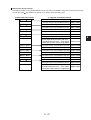
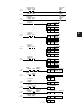
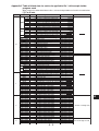
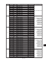
NO. Direction Axis* Signal Name
1
IN Common 24 V power input (+)
2
3
NO. Direction Axis* Signal Name
26 IN Common 24 V power GND (-)
IN Common 24 V power input (+)
OUT
X
27
CW pulse output: differential output +
IN Common 24 V power GND (-)
28 OUT
(Z) [line driver output]
4
OUT
X
CCW pulse output: differential output + 29 OUT
(Z) [line driver output]
5
OUT
6
OUT
X
CW pulse output
30 OUT
IN
8
IN
9
IN
10
IN
X
31 OUT
Positioning completed input
32
IN
General-purpose input (interrupt input, etc.) 33
IN
34
IN
IN
X
35
IN
IN
X
Encoder A phase input +
36
IN
IN
X
Encoder B phase input +
37
IN
Encoder Z phase input +
38
IN Common Common for input (two-way)
15 OUT
Y
IN
Y
39
Y
CW pulse output: differential output +
40 OUT
Y
41 OUT
IN
20
IN
Y
42 OUT
43 OUT
IN
Y
44
IN
General-purpose input (interrupt input, etc.) 45
IN
IN
Y
IN
Y
Upper limit input
46
IN
IN
Y
Sensor input for origin
47
IN
IN
Y
Encoder B phase input -
X
Encoder Z phase input -
Y
CW pulse output: differential output -
Y
CCW pulse output: differential output -
Y
CCW pulse output
Y
General-purpose output (interrupt output, etc.)
Y
Emergency stop input
Y
Driver error input
Y
Lower limit input
Y
Origin proximity input
(A) [24V]
Encoder A phase input +
48
IN
Encoder B phase input +
49
Encoder Z phase input +
Encoder A phase input -
IN
Y
Encoder B phase input -
(A) [line driver or 5 V open collector signal input]
50
(A) [line driver or 5 V open collector signal input]
Y
(A) [line driver or 5 V open collector signal input]
(A) [line driver or 5 V open collector signal input]
25
X
(A) [24V]
(A) [line driver or 5 V open collector signal input]
24
Encoder A phase input -
(A) [24V]
(A) [24V]
23
X
(A) [24V]
(A) [24V]
22
Origin proximity input
(A) [open collector]
Positioning completed input
(A) [24V]
21
X
(A) [open collector output]
Clear deviation output
(A) [24V]
Y
Lower limit input
(A) [line driver output]
CW pulse output +
(A) [open collector]
19
X
(A) [line driver output]
CW pulse output: differential output +
(A) [open collector output]
18 OUT
Driver error input
IN Common Common for input (two-way)
(A) [line driver output]
17 OUT
X
(Z) [line driver or 5 V open collector signal input]
(A) [line driver output]
16 OUT
Emergency stop input
(Z) [line driver or 5 V open collector signal input]
(Z) [line driver or 5 V open collector signal input]
14
X
(Z) [line driver or 5 V open collector signal input]
(Z) [line driver or 5 V open collector signal input]
13
General-purpose output (interrupt output, etc.)
(Z) [24V]
(Z) [line driver or 5 V open collector signal input]
12
X
(Z) [24V]
Sensor input for origin
(Z) [24V]
11
CCW pulse output
(Z) [24V]
Upper limit input
(Z) [24V]
X
X
(Z) [24V]
(Z) [24V]
X
CCW pulse output: differential output -
(Z) [open collector]
(Z) [24V]
X
X
(Z) [open collector output]
Clear deviation output
(Z) [open collector]
7
CW pulse output: differential output -
(Z) [line driver output]
(Z) [open collector output]
X
X
(Z) [line driver output]
IN
Y
Encoder Z phase input -
(A) [line driver or 5 V open collector signal input]
* Z or A in parentheses () in the axis column is for when connector CN3 is connected.
4-5
4
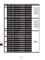
4-3 Connecting (wiring) to external devices
This module
Diode :
IN
Load
4
[1] to [8] show the wiring between this module and external equipment. Pay attention to the following
points during wiring.
Noise from power lines in the periphery or external loads sometimes cause electronic control devices
to malfunction (e.g. positional shift). Adopt the following countermeasures to eliminate malfunction
caused by noise and improve system reliability.
1. Use power leads and cables specified in the instruction manual for the motor driver made of lead
materials for use in wiring.
2. Wire with the power line (AC power supply, motor power leads) separated from the control line
(pulse output line, external I/O signals leads).
3. Use a shielded lead with outer jacket for the control line.
4. Connect the shielded lead to the frame ground (FG) on the driver side.
5. Use a class III grounding, and use thick cable lead material of at least 1.25 mm2 in cross-sectional
area.
6. Use of twisted pair cable is recommended for the power line.
7. Be sure to install a surge absorber to inductive loads (relays, solenoids).
8. When an inductive load is connected to input signals, connect a diode as follows near to the load to
absorb noise.
Use a diode having a peak total reverse
voltage (VRM) of 3 times the load voltage
or more, and a mean rectifying current of
the load current or more.
COM
4-6
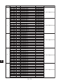
[1] Wiring in open loop control with a general pulse driver
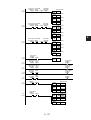
The following example is for the X (Y) axis. Wire in the same way for the Z (A) axis.
JW-12PS(JW-14PS)
Signal
Connector pin No.
IN
26,27
24 VDC power supply
24 VDC(-) input
(COM for output)
+
-
(X, Y common)
1,2 24 VDC(+) input
IN
(X, Y common)
Integrated
power supply
Pulse (stepping) driver
FG
FG
Connector shell
(X, Y common)
Clear deviation output
OUT
X,6 [24 V(-) input is common.]
(Y,18)
OUT
X,31 [24 V(-) input is common.]
(Y,43)
Driver having these
terminals may be
connected with PS.
General-purpose output
3.9kΩ
IN
Positioning completed input
X,7 a contact
(Y,19) (cannot be changed to b contact)
+
Positioning completed signal
output
-
+
3.9kΩ
IN
Driver error input
X,33 b contact
(Y,45) (can be changed to a contact)
+
Ready signal output (alarm)
+
IN
+
14,39 Input signal common
(X, Y common)
IN
IN
IN
IN
IN
IN
3.9kΩ
3.9kΩ
3.9kΩ
3.9kΩ
3.9kΩ
150Ω
IN
IN
150Ω
IN
IN
IN
IN
OUT
OUT
OUT
OUT
2.2kΩ
150Ω
Upper limit (CW) LS input
X,9 b contact (can be changed to a contact)
(Y,21)
Lower limit (CCW) LS input
X,34 b contact (can be changed to a contact)
(Y,46)
Emergency stop input
X,32 b contact (cannot be changed to a contact)
(Y,44)
General-purpose input (external interrupt)
X,8 a contact (can be changed to b contact)
(Y,20)
Origin proximity input
X,35 a contact (can be changed to b contact)
(Y,47)
X,11 Encoder A phase input (+)
(Y,23)
X,36 Encoder A phase input (-)
(Y,48)
Open collector type
origin signal
X,12 Encoder B phase input (+)
(Y,24)
X,37 Encoder B phase input (-)
(Y,49)
Origin sensor input (24 VDC + input)
X,10 a contact (can be changed)
(Y,22)
X,13
(Y,25)
X,38
(Y,50)
X,3 CW pulse differential output (+)
(Y,15)
X,28 CW pulse differential output (-)
(Y,40)
Be sure to wire to FG using a shielded pulse
output signal line.
X,4 CCW pulse differential output (+)
(Y,16)
X,29 CCW pulse differential output (-)
(Y,41)
Suitable resistance
value is required.
Pulse module can be
driven up to 30 mA.
CW pulse input
CW open collector pulse output
OUT
OUT
X,5 (24 V (-) input is common.)
(Y,17)
CCW pulse input
CCW open collector pulse output
X,30 (24 V (-) input is common.)
(Y,42)
FG
4-7
4
[2] Wiring in closed loop control with a general pulse driver
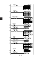
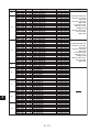
The following example is for the X (Y) axis. Wire in the same way for the Z (A) axis.
JW-12PS(JW-14PS)
Signal
Connector pin No.
IN
26,27
24 VDC power supply
24 VDC (-) input
(COM for output)
+
-
(X, Y common)
1,2 24 VDC (+) input
IN
(X, Y common)
Integrated power
supply
Pulse (stepping) driver
FG
FG
Connector shell
(X, Y common)
Clear deviation output
4
OUT
X,6 (24 V (-) input is common.)
(Y,18)
OUT
X,31 (24 V (-) input is common.)
(Y,43)
General-purpose output
3.9kΩ
IN
Driver having these
terminals may be
connected to PS.
Positioning completed input
X,7 a contact
(Y,19) (cannot be changed to b contact)
+
Positioning completed signal
output
-
+
3.9kΩ
IN
Driver error input
X,33 b contact
(Y,45) (can be changed to a contact)
+
Ready signal output (alarm)
+
IN
+
14,39 Input signal common
(X, Y common)
IN
IN
IN
IN
IN
3.9kΩ
3.9kΩ
3.9kΩ
3.9kΩ
3.9kΩ
Upper limit (CW) LS input
X,9 b contact (can be changed to a contact)
(Y,21)
Lower limit (CCW) LS input
X,34 b contact (can be changed to a contact)
(Y,46)
Emergency stop input
X,32 b contact (cannot be changed to a contact)
(Y,44)
General-purpose input (external interrupt)
X,8 a contact (can be changed to b contact)
(Y,20)
Origin proximity input
X,35 a contact (can be changed to b contact)
(Y,47)
Encoder installed on
drive shaft
FG
IN
150Ω
IN
IN
150Ω
IN
IN
IN
IN
OUT
OUT
OUT
OUT
2.2kΩ
150Ω
FG
Encoder A phase
output (+)
X,11 Encoder A phase input (+)
(Y,23)
X,36 Encoder A phase input (-)
(Y,48)
A phase signal output
Encoder A phase
output (-)
X,12 Encoder B phase input (+)
(Y,24)
X,37 Encoder B phase input (-)
(Y,49)
Encoder B phase
output (+)
Encoder B phase
output (-)
B phase signal output
Encoder Z phase
output (+)
Encoder Z phase
output (-)
Z phase signal output
Origin sensor input (24 VDC + input)
X,10 a contact (can be changed)
(Y,22)
X,13 Encoder Z phase input (+)
(Y,25)
X,38 Encoder Z phase input (-)
(Y,50)
X,3 CW pulse differential output (+)
(Y,15)
X,28 CW pulse differential output (-)
(Y,40)
X,4 CCW pulse differential output (+)
(Y,16)
X,29 CCW pulse differential output (-)
(Y,41)
Be sure to wire to FG using a shielded pulse
output signal line.
CW pulse input
CW open collector pulse output
OUT
OUT
X,5 (24 V (-) input is common.)
(Y,17)
CCW pulse input
CCW open collector pulse output
X,30 (24 V (-) input is common.)
(Y,42)
FG
4-8
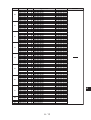
[3] Wiring in closed loop control with a general pulse driver
The following example is for the X (Y) axis. Wire in the same way for the Z (A) axis.
JW-12PS(JW-14PS)
Signal
24 VDC power supply
Integrated power supply
IN
26,27
VDC (-) input
(COM for output)
+
-
(X, Y common)
1,2 24 VDC (+) input
IN
(X, Y common)
Integrated power
supply
Servo driver
FG
FG
Connector shell
(X, Y common)
Clear deviation output
OUT
X,6 (24 V (-) input is common.)
(Y,18)
OUT
X,31 (24 V (-) input is common.)
(Y,43)
Clear deviation
input
General-purpose
output can be
General-purpose used for servo
ON, etc. as it is
output
open collector
output. (See item
"Generalpurpose output.")
General-purpose output
3.9kΩ
IN
+
3.9kΩ
IN
Positioning completed input
Servo ON
Positioning completed signal
output
X,7 a contact (cannot be changed to b contact)
(Y,19) (not required in closed loop control)
Driver error input
X,33 b contact (can be changed to a contact)
(Y,45)
+
Ready signal output (alarm)
+
IN
+
14,39 Input signal common
(X, Y common)
IN
IN
IN
IN
IN
IN
3.9kΩ
3.9kΩ
3.9kΩ
3.9kΩ
3.9kΩ
150Ω
IN
IN
150Ω
IN
IN
2.2kΩ
Upper limit (CW) LS input
X,9 b contact (can be changed to a contact)
(Y,21)
Lower limit (CCW) LS input
X,34 b contact (can be changed to a contact)
(Y,46)
Emergency stop input
X,32 b contact (cannot be changed to a contact)
(Y,44)
General-purpose input (external interrupt)
X,8 a contact (can be changed to b contact)
(Y,20)
Origin proximity input
X,35 a contact (can be changed to b contact)
(Y,47)
X,11 Encoder A phase input (+)
(Y,23)
X,36 Encoder A phase input (-)
(Y,48)
Encoder A phase output (+) A phase signal output
X,12 Encoder B phase input (+)
(Y,24)
X,37 Encoder B phase input (-)
(Y,49)
Encoder B phase output (+) B phase signal output
Encoder A phase output (-)
Encoder B phase output (-)
Origin sensor input (24 VDC + input)
X,10 a contact (can be changed to b contact)
(Y,22)
IN
IN
150Ω
X,13 Encoder Z phase input (+)
(Y,25)
X,38 Encoder Z phase input (-)
(Y,50)
Encoder Z phase output (+)
Z phase signal output
Encoder Z phase output (-)
CW pulse input
OUT
OUT
X,3 CW pulse differential output (+)
(Y,15)
X,28 CW pulse differential output (-)
(Y,40)
CW pulse differential input (+)
X,4 CCW pulse differential output (+)
(Y,16)
X,29 CCW pulse differential output (-)
(Y,41)
CCW pulse differential input (+)
CW pulse differential input (-)
CCW pulse input
OUT
OUT
CCW pulse differential input (-)
CW open collector pulse output
OUT
OUT
X,5 (24 V (-) input is common.)
(Y,17)
FG
CCW open collector pulse output
X,30 (24 V (-) input is common.)
(Y,42)
Be sure to wire to FG using a shielded pulse
output signal line.
4-9
4
[4] Wiring in open loop control with a general servo driver
The following example is for the X (Y) axis. Wire in the same way for the Z (A) axis.
JW-12PS(JW-14PS)
Signal
Connector pin No.
24 VDC power supply
24 VDC (-) input
26,27 (COM for output)
(X, Y common)
IN
+
-
1,2 24 VDC (+) input
IN
Suitable resistance
value is required.
Pulse module can
be driven up to 30
mA.
(X, Y common)
Integrated power
supply
Servo driver
FG
FG
Connector shell
(X, Y common)
Clear deviation output
Clear
deviation
X,6 (24 V (-) input is common.)
(Y,18)
OUT
General-purpose
output can be
used for servo
ON, etc. as it is
open collector
output. (See item
"General-purpose
output.")
General-purpose output
4
X,31 (24 V (-) input is common.)
(Y,43)
OUT
IN
IN
3.9kΩ
3.9kΩ
Positioning completed input
a contact
X,7 (cannot be changed to b contact)
(Y,19)
+
Driver error input
b contact
X,33 (can be changed to a contact)
+
General-purpose
output
Positioning completed signal
output
Ready signal output (alarm)
(Y,45)
IN
14,39 Input signal common
(X, Y common)
3.9kΩ
IN
IN
IN
IN
IN
IN
3.9kΩ
3.9kΩ
3.9kΩ
3.9kΩ
150Ω
IN
IN
150Ω
IN
IN
IN
IN
OUT
OUT
OUT
OUT
2.2kΩ
150Ω
Upper limit (CW) LS input
X,9 b contact (can be changed to a contact)
(Y,21)
Lower limit (CCW) LS input
X,34 b contact (can be changed to a contact)
(Y,46)
Emergency stop input
X,32 b contact (cannot be changed to a contact)
(Y,44)
General-purpose input (external interrupt)
X,8 a contact (can be changed to b contact)
(Y,20)
Origin proximity input
X,35 a contact (can be changed to b contact)
(Y,47)
X,11 Encoder A phase input (+)
(Y,23)
X,36 Encoder A phase input (-)
(Y,48)
X,12 Encoder B phase input (+)
(Y,24)
X,37 Encoder B phase input (-)
(Y,49)
Origin sensor input (24 VDC + input)
X,10 a contact (can be changed to b contact)
(Y,22)
Encoder Z phase output (+)
X,13 Encoder Z phase input (+)
(Y,25)
X,38 Encoder Z phase input (-)
(Y,50)
Encoder Z phase output (-)
X,3 CW pulse differential output (+)
(Y,15)
X,28 CW pulse differential output (-)
(Y,40)
X,4 CCW pulse differential output (+)
(Y,16)
X,29 CCW pulse differential output (-)
(Y,41)
CW pulse differential input (+)
CW pulse differential input (-)
CCW pulse differential input (+)
CCW pulse differential input (-)
CW open collector pulse output
OUT
OUT
X,5 (24 V (-) input is common.)
(Y,17)
FG
CCW open collector pulse output
X,30 (24 V (-) input is common.)
(Y,42)
Be sure to wire to FG using a shielded pulse
output signal line.
4 - 10
[5] Wiring of the input section
Use a switch, for example, having a switching capacity of 5 mA or more for each input. Connect a
power supply to b contacts when not in use. (b contacts can also be changed to a contacts in
parameters except for the emergency stop input.)
24 VDC power supply
+
-
JW-12PS/14PS
+
Pins 14, 39 Input signal common
(common to X, Y, Z, A axes)
3.9kΩ
Upper limit (CW) LS input
b contact
X(Z)-axis pin 9 (can be changed to a contact)
Y(A)-axis pin 21
3.9kΩ
Lower limit (CCW) LS input
b contact
X(Z)-axis pin 34 (can be changed to a contact)
Y(A)-axis pin 46
470Ω
470Ω
3.9kΩ
470Ω
X(Z)-axis pin 32
Y(A)-axis pin 44
Emergency stop input
b contact
(cannot be changed to a contact)
470Ω
Driver error input
b contact
X(Z)-axis pin 33 (can be changed to a contact)
Y(A)-axis pin 45
470Ω
General-purpose input
(external interrupt)
a contact
X(Z)-axis pin 8 (can be changed to b contact)
Y(A)-axis pin 20
3.9kΩ
3.9kΩ
3.9kΩ
470Ω
3.9kΩ
470Ω
Origin proximity input
a contact
X(Z)-axis pin 35 (can be changed to b contact)
Y(A)-axis pin 47
X(Z)-axis pin 7
Y(A)-axis pin 19
Positioning completed input
a contact
(cannot be changed to b contact)
4 - 11
Connected to sensors, relays, switches, etc.
4
[6] Wiring of CW/CCW pulse output signals
(1) Wiring in an open collector connection with a general pulse driver
24 VDC
power supply
JW-12PS(JW-14PS)
+
Be sure to wire to FG using a shielded
pulse output signal line.
(Connected the shielded lead to the
shield of the connector.)
24 VDC (-) input
26,27 (COM for output)
(common to
X, Y, Z, A axes)
4
Driver side
-
Suitable resistance
value is required.
Open collector of
pulse module can be
driven up to 30 mA.
CW pulse input
CW open collector
pulse output
X (Z) axis pin 5 (24V (-) input is common.)
Y (A) axis pin 17
CCW open collector
pulse output
X (Z) axis pin 30 (24V (-) input is common.)
Y (A) axis pin 42
CCW pulse input
FG
(2) Wiring in connection with general differential reception-type driver
JW-12PS(JW-14PS)
Driver side
AM26LS32 or
equivalent product
AM26LS31 or equivalent product
X (Z) axis pin 3 CW pulse differential output (+)
Y (A) axis pin 15
X (Z) axis pin 28 CW pulse differential output (-)
Y (A) axis pin 40
CW pulse differential input (+)
CW pulse differential input (-)
X (Z) axis pin 4 CCW pulse differential output (+)
Y (A) axis pin 16
X (Z) axis pin 29 CCW pulse differential output (-)
Y (A) axis pin 41
CCW pulse input
CCW pulse differential input (+)
CCW pulse differential input (-)
FG
[7] Wiring of clear deviation output/general-purpose output signals
JW-12PS(JW-14PS)
24 VDC power
supply
+
Driver side
-
Suitable resistance
value is required.
Open collector of
pulse module can be
driven up to 30 mA.
24 VDC (-) input
26,27 (COM for output)
(common to
X, Y, Z, A axes)
Clear deviation input
Clear deviation output
X (Z) axis pin 6 (24 V (-) input is common.)
Y (A) axis pin 18
Servo ON input
General-purpose output
X (Z) axis pin 31 (24 V (-) input is common.)
Y (A) axis pin 43
General-purpose output can be
used as a servo ON contact as it
its application is not determined.
4 - 12
FG
[8] Wiring of origin signal
(1) When this signal is used in an open loop
When the differential signal origin (Z phase) signal is output from the driver
Differential signal of
servo driver
JW-12PS(JW-14PS)
FG
Z-phase signal
output
2.2kΩ
150Ω
750Ω
X (Z) axis pin 13 Encoder Z phase input (+)
Y (A) axis pin 25
X (Z) axis pin 38 Encoder Z phase input (-)
Y (A) axis pin 50
Encoder Z phase
output (+)
AM26LS31 or
equivalent
Encoder Z phase
output (-)
4
Be sure to use a shielded lead for the
signal from the encoder and wire as FG.
When connecting an open collector type origin signal
Open collector type
(e.g. driver) origin signal
24VDC
JW-12PS(JW-14PS)
+
Encoder B phase input (-)
Origin sensor input (24 VDC + input)
X (Z) axis pin 10 A contact (can be changed)
Y (A) axis pin 22
2.2kΩ
-
Open collector
type origin signal
150Ω
750Ω
X (Z) axis pin 38 Encoder Z phase input (-)
Y (A) axis pin 50
(2) When this signal is used in a closed loop
Wire the feedback signal (signal from the encoder) from the driver as shown below.
The driver (encoder) will not pose any problems if it can output a signal equivalent to AM26LS31.
• For details on the signal level on the driver side, check with the driver manufacturer.
Servo driver encoder signal output.
In the case of a pulse motor, the
output of the encoder signal
installed on the drive shaft
JW-12PS(JW-14PS)
150Ω
750Ω
X (Z) axis pin 11 Encoder A phase input (+)
Y (A) axis pin 23
X (Z) axis pin 36 Encoder A phase input (-)
Y (A) axis pin 48
150Ω
750Ω
X (Z) axis pin 12 Encoder B phase input (+)
Y (A) axis pin 24
X (Z) axis pin 37 Encoder B phase input (-)
Y (A) axis pin 49
3.9kΩ
150Ω
750Ω
X (Z) axis pin 10 Origin sensor input (24 VDC + input)
Y (A) axis pin 22 A contact (can be changed)
X (Z) axis pin 13 Encoder Z phase input (+)
Y (A) axis pin 25
X (Z) axis pin 38 Encoder Z phase input (-)
A phase signal
FG
Encoder A phase
output
output (+)
AM26LS31 or equivalent
Encoder A phase
output (-)
Encoder B phase B phase signal output
output (+)
AM26LS31 or equivalent
Encoder B phase
output (-)
Encoder Z phase
output (+)
Encoder Z phase
output (-)
Y (A) axis pin 50
Be sure to use a shielded lead for the
signal from the encoder and wire as FG.
4 - 13
Z phase signal output
AM26LS31 or equivalent
Chapter 5 Data Transfer
5-1
Data transfer between this module and the JW50H/70H/
100H control module
256-byte special I/O data area is used for transferring data between this module and the JW50H/70H/
100H control module. I/O refresh area on which this module is mounted cannot be used for data
transfer.
The following shows the data required for each program mode. Each of these data items must be
transferred from the JW50H/70H/100H control module as block data, and are all exchanged on the
256-byte special I/O data area.
Actually, 64 bytes (block transfer read data and block transfer write data) each are assigned to the
block data read area (PS→PC) and the block data write area (PS→PC), respectively.
(See the following page.)
Data required for direct operation (open loop connection)
• Parameter 1 (block data No.00) data of each axis
• M output range data (block data No.02) only when M output is used
• Acceleration/deceleration time data (block data No.03) only when multiple acceleration/
deceleration times are set
Data required for program operation and speed control operation (open loop connection)
• Parameter 1 (block data No.00) data of each axis
• Various setting data required for program operation. M output, acceleration/deceleration time,
dwell timer, speed, position, step data, etc. (block data No.02 to No.31)
Data required for other basic operations (origin return, Move origin, jog operation, teaching, etc.)
• Parameter 1 (block data No.00) data of each axis
Data required for special control (closed loop control, absolute system)
• Parameter 2 (block data No.01) data of each axis
When building a highly reliable closed loop system or an absolute system (comprising limited
connectable servos) for holding current value data when a power interruption occurs, parameter 2
(block data No.01) must be set in all the startup methods of operation modes
above.
Caution
to
described
(Address annotation)
• This chapter annotates addresses in special I/O data area on the JW50H/70H/100H control
module that are used by this module as follows:
Address
Byte addresses
Relay addresses
Annotation
N+*****
n+*****
N and n are the top address of special I/O data when any given I/O has been registeared.
5-1
5
Outline of data exchange
Control module side
Data memory
5
Refresh area 1,
2 bytes
Refresh area 1 input
(use not allowed)
Refresh area 2,
256 bytes
Common RAM (32 Kbytes)
Input relays
(16 bytes/axis)
Input relays
(16 bytes/axis)
Total 64 bytes
Total 64 bytes
Read data area
for block transfer
(common to each
axis)
64 bytes
I/O refresh
See next
page.
JW-14PS (JW-12PS) side
Present position,
error code, status,
etc.
Read data area
for block transfer
(common to each
axis)
64 bytes
Output relays
(16 bytes/axis)
Output relays
(16 bytes/axis)
Total 64 bytes
Total 64 bytes
Write data area for
block transfer
(common to each
axis)
64 bytes
Write data area for
block transfer
(common to each
axis)
64 bytes
Parsing of operation
instructions, parsing
of block data
transfer instructions,
etc.
Block data
(operation data)
X-axis block 00
Block data
X-axis block 31
X-axis block 00
Y-axis block 00
X-axis block 31
Y-axis block 00
Y-axis block 31
Y-axis block 31
Register to
file registers,
etc.
Z-axis block 00
See page
5-4 and
Appendix 4.
Z-axis block 31
Z-axis block 00
A-axis block 00
Z-axis block 31
A-axis block 31
A-axis block 00
Data
save
A-axis block 31
At power ON
and restart
Flash ROM
• "Block data" is operation data
(e.g. parameters, zone data, speed data,
position data, step operation data).
(Note) The above figure is for the JW-14PS. The Z- and A-axes are not supported on the JW-12PS.
5-2
[1] Refresh area
(1) Refresh area 1: I/O relay area (2 bytes)
Address
1st byte
2nd byte
Description
Use not allowed
• Addresses are assigned according to the position where this module is mounted and by optional
I/O registration of the JW50H/70H/100H control module.
(2) Refresh area 2: Special I/O data area (256 bytes)
Address
Number
of bytes Direction*
Description
For X-axis
N+0000 to 0017 16
N+0020 to 0037 16
PC←PS
N+0040 to 0057 16
Input
relays
N+0060 to 0077 16
N+0100 to 0177 64
⇒See
For Z-axis (JW-14PS only) item 5-2.
For A-axis (JW-14PS only)
(Read) data storage area for block transfer
256
For X-axis
N+0200 to 0217 16
N+0220 to 0237 16
N+0240 to 0257 16
For Y-axis
PC→PS
Output
relays
N+0260 to 0277 16
For Y-axis
⇒See
For Z-axis (JW-14PS only) item 5-2.
For A-axis (JW-14PS only)
(Write) data storage area for block transfer
N+0300 to 0377 64
* PC=JW50H/70H/100H control module, PS=JW-12PS/14PS
• N is the top address of special I/O data area (256 bytes) that is assigned to this module by
optional I/O registration. The following table shows the addresses of refresh area 2 when N is
set to 1000 or 49000.
Address
Setting Example
N+0000 to 0017
1000 to
1017
49000 to 49017
N+0020 to 0037
1020 to
1037
49020 to 49037
N+0040 to 0057
1040 to
1057
49040 to 49057
N+0060 to 0077
1060 to
1077
49060 to 49077
N+0100 to 0177
1100 to
1177
49100 to 49177
N+0200 to 0217
1200 to
1217
49200 to 49217
N+0220 to 0237
1220 to
1237
49220 to 49237
N+0240 to 0257
1240 to
1257
49240 to 49257
N+0260 to 0277
1260 to
1277
49260 to 49277
N+0300 to 0377
1300 to
1377
49300 to 49377
5-3
5
[2] Block data
The block data for each axis is comprised as shown in the following table in 64-byte units. (The
block data must be set independently for each axis.)
Block
No.
Number
of bytes
Remarks
Direct operation/
program operation
Reference
page
0
Parameter 1 (regular parameters) 0000 to 0077
*2
1
Parameter 2 (special parameters) 0100 to 0177
*2
2
M output range data (0 to 7)
0200 to 0277 4×2×8
*2
Acceleration time data (1 to 8)
0300 to 0337 4×8
*2
Deceleration time data (1 to 8)
0340 to 0377 4×8
*2
4
Dwell timer data (01 to 16)
0400 to 0437 2×16
For program operation 5-5 (3)
5
Speed data (No.1 to 16)
0500 to 0577 4×16
6
Speed data (No.17 to 32)
0600 to 0677 4×16
7
Speed data (No.33 to 48)
0700 to 0777 4×16
8
Speed data (No.49 to 64)
1000 to 1077 4×16
9
Position data (No.1 to 16)
1100 to 1177 4×16
10
Position data (No.17 to 32)
1200 to 1277 4×16
11
Position data (No.33 to 48)
1300 to 1377 4×16
12
Position data (No.49 to 64)
1400 to 1477 4×16
13
Position data (No.65 to 80)
1500 to 1577 4×16
14
Position data (No.81 to 76)
1600 to 1677 4×16
15
Position data (No.97 to 99)
1700 to 1713 4×3
16
Step data (No.01 to 08)
2000 to 2077 8×8
17
Step data (No.09 to 16)
2100 to 2177 8×8
18
Step data (No.17 to 24)
2200 to 2277 8×8
19
Step data (No.25 to 32)
2300 to 2377 8×8
20
Step data (No.33 to 40)
2400 to 2477 8×8
21
Step data (No.41 to 48)
2500 to 2577 8×8
22
Step data (No.49 to 56)
2600 to 2677 8×8
23
Step data (No.57 to 64)
2700 to 2777 8×8
24
Step data (No.65 to 72)
3000 to 3077 8×8
25
Step data (No.73 to 80)
3100 to 3177 8×8
26
Step data (No.81 to 88)
3200 to 3277 8×8
27
Step data (No.89 to 96)
3300 to 3377 8×8
28
Step data (No.97 to 99)
3400 to 3427 8×3
29
Reserved area
3500 to 3577
30
Reserved area
3600 to 3677
31
Reserved area
3700 to 3777
3
5
PC side
memory
address*1
Description
Item 5-3
5-5 (1)
5-5 (2)
For program
operation
5-6 (4)
For program
operation
5-6 (5)
For program
operation
5-7 (6)
*2 Shared by both direct operation and program operation
Total 0000 to 3777 (2048 bytes/axis)
*1 In this example, the PC side memory address is the address where data is assigned
continuously with 0000 set as the top address of the block data.
5-4
The following shows the formats for each of the data items. (Setting data is annotated entirely in BCD.)
(1) M output range data (0 to 7)
Setting range of upper limit value/lower limit value: -9999999 to +9999999 (-9999999 to +9999999
pulses) in 1-pulse increments
Bit
Upper limit value Lower limit value
Address
C+0000
C+0001
C+0002
C+0003
C+0004
C+0005
C+0006
C+0007
7
6
5
4
A/I
Sign
3
100
102
104
106
Sign
100
102
104
106
101
103
105
1
10
103
105
A/I
2
1
0
5
• "Sign": plus=0, minus=1, absolute values independent of the "A/I" bit setting
• C is the leading address of each M output 0 to 7.
(2) Acceleration time/deceleration time data
Setting range: 0 to 250000 (0 to 250000 ms) in 1-ms increments
Acceleration time data (1 to 8)
Address
D+0000
D+0001
D+0002
D+0003
Bit
7
101
103
105
6
5
4
3
100
102
104
2
1
0
2
1
0
2
1
0
• D is the leading address of each acceleration time data 1 to 8.
Deceleration time data (1 to 8)
Address
E+0000
E+0001
E+0002
E+0003
Bit
7
101
103
105
6
5
4
3
100
102
104
• E is the leading address of each deceleration time data 1 to 8.
(3) Dwell timer data (01 to 16)
Setting range: 0 to 9999 (0 to 99990 ms) in 10-ms increments
Address
F+0000
F+0001
Bit
7
101
103
6
5
4
3
100
102
• F is the leading address of each dwell timer data 01 to 16.
5-5
(4) Speed data (No.01 to 64)
Setting range: 0 to 500000 (0 to 500 kpps) in 1-pps increments
Address
G+0000
G+0001
G+0002
G+0003
Bit
7
101
103
105
6
5
4
3
100
102
104
2
1
0
• G is the top address of each speed data No.01 to 64.
(5) Position data (No.01 to 99)
Setting range: -9999999 to +9999999 (-9999999 to +9999999 pulses) in 1-pulse increments
Address
5
H+0000
H+0001
H+0002
H+0003
Bit
7
101
103
105
6
5
4
A/I
Sign
3
100
102
104
106
2
1
0
"A/I": 0=absolute value, 1=relative value, "Sign": Plus=0, Minus=1
• H is the top address of position data No.01 to 99.
• Position instructions at writing of interrupt output position data becomes an absolute value regardless of
the setting of "A/I", and "A/I" becomes the bit for specifying interrupt output ON/OFF.
(When "A/I" is set to "1", interrupt output is ON, and when "A/I" is set to "0", interrupt output is OFF.)
• Position instructions at speed control startup become the travel distance after an interrupt, and the
"Sign" and "A/I" bits are disabled.
5-6
(6) Program operation step data (No.01 to 99)
Bit
J+0007
Address
7
J+0000
J+0001
J+0002
J+0003
J+0004
J+0005
J+0006
When operation pattern
is set to "Single step",
"Automatic" and "
Continuous"
When operation pattern
is set to "Speed
operation"
6
5
4
3
2
1
0
Axis designation (4=X-axis, 5=X-axis, 6=X-axis, 7=X-axis) Operation pattern (0, 1, 2, 3) ⇒ See below.
Acceleration time No. (0 to 8) *0 is parameter value. Deceleration time No. (0 to 8) *0 is parameter No.
Startup speed No. (00 to 64) *00 is parameter value.
Target speed No. (00 to 64) *00 is jog operation speed of parameter value.
Dwell timer No. (00 to 16) *00 is "dwell timer disabled."
Position data No. (01 to 99)
Output code (01 to 99)
Jump destination step No. (00 to 99)
• When set to "00", the program advances to the next (incremented by "1") step.
Speed No. after external interrupt (00 to 64)
• When set to "00", the speed after parameter interrupt is enabled.
• J is the top address of each step data No.01 to 99.
Operation patterns (above address J+0000 bits 0 to 3)
Operation pattern Setting
Single step
Automatic
0
1
Continuous
2
Speed control
3
Description
The program executes the current step data, and stands by for the next startup.
• When the dwell timer is enabled, the positioning completed signal turns ON after
the time preset to the dwell timer has elapsed.
The program executes the current step data, stops operation for the time preset to
the dwell timer, and automatically starts operation at the next (incremented by "1")
step or the step at the jump destination step No.
The program executes the current step data, and starts operation at the next
(incremented by "1") step or the step at the jump destination step No. without
stopping at the target position.
• The dwell timer is disabled in this operation mode.
The program operates at the speed preset in the current step data.
The operation direction follows the direction (sign) of the step data position data,
and the present position is also updated during operation.
When the sign is "0" (forward), the program operates at the preset speed in the
CW direction, and when the sign is "1" (reverse), the program operates at the
preset speed in the CCW direction.
• At startup, only the "Sign" bit of the step data position data is enabled.
• Operation can be stopped by "External interrupt" and "Deceleration stop" during
speed control operation.
• When an external interrupt input is used to perform interrupt jog feed, the
"Position data" preset in the step data becomes the travel distance after the
interrupt, and the "Speed No. after external interrupt" preset in the step data
becomes the speed after the interrupt. The travel direction after the interrupt is
the same direction as the direction of operation.
The "present value zero preset" at an external interrupt is set at "Present position
at speed control operation" in parameter 1 (address A+0006).
* When parameter 1 (address A+0006) is set to "02", the present position remains "0".
⇒ See page 5-16.
5-7
5
Operation patterns and jump destinations in program operation
Four settings are provided for the operation patterns (described on the previous page). Combining
jump ON/OFF conditions with these operation patterns results in the seven patterns shown in the table
below.
Operation Jump
pattern destination
Name
*
0
00
Single step
*
1
00
Automatic
5
2
3
0
1
2
00
00
**
**
**
*
Continuous
* Speed
control
Description
The program executes the current
step data, stops operation, and
stands by for startup by the next step
data.
The program executes the current
step data, stops operation for the
time preset to the dwell timer, and
automatically starts operation at the
next (incremented by "1") step.
The program executes the current
step data, and program execution is
continued at the next (incremented
by "1") step without stopping
operation at the target position.
This is the conventional continuous
output pattern.
Pulse output is maintained at the
speed preset in the current step data.
The present position is also
calculated during continuous output,
and the direction of pulse output
follows the sign of the position data.
To stop this output, use either the
deceleration stop instruction or
external interrupt jog feed.
Jump single
step
The program executes the current
step data, stops operation, and
stands by for a startup at the step
No. (**) entered as the jump step No.
Jump
automatic
The program executes the current
step data, stops operation for the
time preset to the dwell timer, and
automatically starts operation at the
step No. (**).
Jump
continuous
After the program executes the
current step data, the program
continues to execute the step data
specified by the jump step No.
without stopping operation at the
target position.
* Jump is not performed when "00" is set.
5-8
Operation
Target speed
Deceleration
Startup
speed
Stop at startup
speed
Time
Acceleration
Startup
Target position
Target speed
Time
Dwell timer
Startup
Start of next position data
Target speed
Target speed of
next position data
Time
Startup
Pass target position
Target speed
Startup
Time
Stop
Deceleration stop instruction
(Note) Finally, the speed reaches
the startup speed.
Target
speed
Time
Dwell timer
Startup
Startup by step No. of **
Target speed specified
by jump No. (**)
Pass target position
About startup axis in program operation, and interpolation operation
Startup
This module can simultaneously start single-step operation of each of the four axes, and perform
linear interpolation of two axes. It can also perform start interpolation of two axes with single-step
operation of the other axes, and simultaneously start linear interpolation of two sets of two axes.
On the JW-14PS, the combination of the two axes to interpolate can be selected as desired.
However, a duplicate instruction error occurs when 2-axis linear interpolation is instructed while
the axes programmed for 2-axis linear interpolation are already in operation.
Interpolation data
When performing linear interpolation on two axes, linear interpolation is possible using the step
data of any the axes (X, Y, Z, or A). The data used for linear interpolation follows the axis data of all
step data with the exception of coordinate data. The data of the axis to be interpolated is used as
the coordinate data.
For example, when performing linear interpolation on the X- and Y-axes using the step data of the
Z-axis, all of the data of the Z-axis is used as the acceleration/deceleration time, startup speed,
target speed, and dwell timer data. The data of the X- and Y-axes is used only for the coordinate
data, and the target speed (speed data) becomes the interpolation speed.
5
[Example] Step data when performing linear interpolation on the X- and Y-axes in program operation
of Z-axis
Z-axis step data
4(BCD)
Step No.1
0(BCD)
X/Y-axis designation ("3" in Hex) - Operation pattern 0 (single step)
8(BCD)
Acceleration time No.4 (Z-axis data) - Deceleration time No.8 (Z-axis data)
15(BCD)
11(BCD)
Startup speed No.15 (Z-axis data)
Target speed No.11 (Z-axis data)
00(BCD)
Dwell timer disabled (Z-axis data)
02(BCD)
Position data No.02 (X/Y-axis data)
01(BCD)
Output code 01 (indicated in Z-axis relay area)
09(BCD)
Output code 9
15(BCD)
Jump destination 15
indicates ON.
The following shows the relationship between speed and coordinates during operation using the
above data.
Y-axis
Final coordinate (X-axis No.2, Y-axis No.2)
Interpolation at speed
of Z-axis No.11
X-axis
5-9
5-2
Operation data area
This section describes the assignments and functions of refresh area 2 (pages 5-2 and 5-3).
[1] Assignment of special I/O data area
Special I/O data area (256 bytes) is used as the refresh area.
* JW-14PS only
(1) Input section (N+0000 to 0177)
I/O
Byte address of data memory
(N+****)
Details
Bit
Function
X-axis Y-axis Z-axis* A-axis*
No. Page
0
Operation ready (U.R.)
1
Positioning completed
2
Busy flag
0
Operation readying
1
Operation ready
Completed
At startup
3
5
0000 0020 0040 0060
4
Program operation startup standby
No origin flag
0
Non-busy state
1
Busy state
0
Non-startup standby
1
Startup standby state
0
Origin
1
No origin
5
Teaching completed
6
BD.REQ (block data request) signal
0
Block transfer disabled
• Block transfer is possible only when this flag is ON.
1
Block transfer enabled
Error flag
0
No error
1
Error
0
Instruction value display
1
Encoder input display
0
Interrupt output OFF
1
Interrupt output ON
5-12
Completed
At start
7
0
Present position display mode monitor
1
Interrupt output monitor
2
Driver communications completed
Completed
• Enabled only when absolute value control is enabled.
At start
0001 0021 0041 0061
3 to 7 Reserved function
Input
(PC←PS)
0002 0022 0042 0062
0003 0023 0043 0063
0
CW limit input signal
1
CCW limit input signal
2
Origin proximity input signal
3
Origin input signal
4
General-purpose input signal
5
Driver error input signal
6
Emergency stop input signal
7
Positioning completed signal
0
M output 0
1
M output 1
2
M output 2
3
M output 3
4
M output 4
5
M output 5
6
M output 6
7
M output 7
State of input signals
of each axis is
monitored.
1: ON
o: OFF
State of each M output
(zone) signal is
monitored.
1: ON
0: OFF
0004 0024 0044 0064 0 to 7 Present position ( 101 100 )
0005 0025 0045 0065 0 to 7 Present position ( 103 102)
0006 0026 0046 0066 0 to 7 Present position ( 105 104)
0007 0027 0047 0067 0 to 7 Present position (sign 106)
0010 0030 0050 0070 0 to 7 Output code (00 to 99) *Enabled at program operation
0011 0031 0051 0071 0 to 7 Step No. (00 to 99) *Enabled at program operation
0012 0032 0052 0072 0 to 7 Error code, lower (00 to 99)
0013 0033 0053 0073 0 to 7 Error code, upper (00 to 99)
0014 0034 0054 0074 0 to 7 Reserved function
5 - 10
5-13
0015 0035 0055 0075 0 to 7 Reserved function
0016 0036 0056 0076 0 to 7
Input
(PC←PS) 0017 0037 0057 0077 0 to 7
64
0100 to 0177
bytes
Reserved function
Block data No. monitor (00 to 31) *Read block No. is indicated.
(2) Output section (N+0200 to 0377)
I/O
Byte address of data memory
(N+****)
* JW-14PS only
Details
Bit
Function
No. Page
X-axis Y-axis Z-axis* A-axis*
Start 1 [ ↑ ]
0
1
At program
operation
2
3
0200 0220 0240 0260
Continuous startup
1
Single-step startup
Step No. enable
0
Set disabled
1
Set enabled
External input startup selection
Start 2 [ ↑ ]
Position control/speed
control setting
0
Position control startup
1
Speed control startup
Jog+
(CW jog operation instruction)
0
Stop
1
Operation
Jog(CCW jog operation instruction)
0
Stop
1
Operation
0
OFF
1
ON
0
Disabled
1
Enabled
At direct
operation
0
Zero return [ ↑ ]
1
Move origin [ ↑ ]
2
Present position preset [ ↑ ]
3
Deceleration stop [ ↑ ]
4
Forced intervention startup [ ↑ ]
5
Clear deviation
6
Override enable
7
Clear error [ ↑ ] (pulse output inhibit cancel)
0
Teaching [ ↑ ]
1
Clear error [ ↑ ]
General-purpose output
2
0202 0222 0242 0262
0
single-step startup setting
5
7
Output
(PC→PS)
Continuous startup/
4
6
0201 0221 0241 0261
5-13
Data storage area at block data read (PC←this unit transfer buffer
area) *Area common to each axis
0
OFF
1
ON
Block data write *Executed at each scan when ON
4
Block data read *Executed at each scan when ON
5
6
Block data save (write to flash ROM) [ ↑ ] *Enabled on X-axis only (batch operation for 4 axes)
0 Instruction value
Switching of present
position display mode
1 Encoder input (at closed loop control)
7
Read absolute present position [ ↑ ] *Enabled only when absolute value control is enabled
0203 0223 0243 0263 0 to 7 Step No. at program operation (00 to 99)
0204 0224 0244 0264 0 to 7 Position No. at teaching (00 to 99)
0205 0225 0245 0265 0 to 7 Designation of block data block No. (00 to 31)
0206 0226 0246 0266 0 to 7 Override coefficient, lower (00 to 99)
Set override coefficient within
range 000 to 999%.
0207 0227 0247 0267 0 to 7 Override coefficient, upper (00 to 09)
5
4
0212 0232 0252 0272 0 to 7 Position instruction value (10 10 )
6
0213 0233 0253 0273 0 to 7 Position instruction value (sign A/I 10 )
1
0
0214 0234 0254 0274 0 to 7 Speed instruction value (10 10 )
3
2
Speed
instruction
value
(10
10
)
0215 0235 0255 0275 0 to 7
5-16
Becomes the travel distance
after an interrupt in the case
of speed control operation.
Sign indicates direction of
operation.
When 000000, the jog
operation speed of the
parameter becomes the
speed instruction value.
5
4
0216 0236 0256 0276 0 to 7 Speed instruction value (10 10 )
0 to 3 Acceleration time No. (0 to 8) *When 0, setting value of parameter
0217 0237 0257 0277
4 to 7 Deceleration time No. (0 to 8) *When 0, setting value of parameter
Data storage area at block data write (PC->this unit transfer buffer
64
0300 to 0377
Byte area) *Area common to each axis
5 - 11
5-14
5-15
3
1
0
0210 0230 0250 0270 0 to 7 Position instruction value (10 10 )
3
2
0211 0231 0251 0271 0 to 7 Position instruction value (10 10 )
5
5-17
第
6
章
[2] Description of functions
5
←PS)
(1) Input section (PC←
to correspond to the numbers on pages 5-10 and 5-11.
Operation ready (U.R.)
This input turns ON when normal parameters and block data are stored to this module, and this
module is ready for operation.
Positioning completed
This input targets the following operations: program operation startup, direct operation startup, jog
operation, zero return, and move origin.
When the external positioning completed signal is set to "Disabled" (dependent on setting at
parameter 1- address A+0000 - bit 7)
This input turns OFF at various startups, and turns ON after pulse output from this module is
completed.
This input turns OFF at power ON, initial start, and the next startup.
• This input immediately turns ON when "Positioning monitoring time" is set to "0000".
• When a time is preset to the dwell timer in program operation, this input turns ON after pulse
output is completed, and the time preset to the dwell timer has elapsed.
• This input stays OFF when an emergency stop or deceleration stop is performed during
operation.
When the external positioning completed signal is set to "Enabled" (dependent on setting at
parameter 1- address A+0000 - bit 7)
This input turns OFF at various startups, and turns ON when the positioning completed signal
from the driver turns ON.
• When a time is preset to the dwell timer in program operation, this input turns ON after the
position completed signal from the driver turns ON and the time preset to the dwell timer has
elapsed.
• This input stays OFF when an emergency stop or deceleration stop is performed during
operation.
• Set the positioning completed signal (INP) of the servo driver to turn OFF during operation
and to turn ON while operation is stopped.
• An error occurs if the external positioning completed signal does not turn OFF within the
"Positioning monitoring time" set at parameter 1 - address A+0066 and 0067 after pulse
output from this module is completed.
Busy flag
This flag turns ON at start of processing, and OFF when processing is completed.
• The busy flag turns ON during execution of various positioning operations and speed control
operation, jog operation, teaching, block data save, present value preset, and other processes.
• The busy flag turns OFF at power ON and initial start.
• When an axis is specified in program operation, the bit corresponding to the specified
operational axis is enabled.
Program operation startup standby
This input turns ON while the program is standing by for the next startup after program operation
startup (continuous startup or single-step startup), and turns OFF when program execution is next
restarted.
• When the operation pattern is set to "Automatic" or "Continuous," this input does not turn ON
after operation is completed.
• In the case of a single-step startup, this input turns ON after completion of operation
programmed to each step independently of the operation pattern.
• This input turns OFF when a deceleration stop/emergency stop is executed or operation has
stopped due to an error during program operation.
No origin flag
This flag turns OFF when the origin is confirmed, and ON when it is not confirmed.
Teaching completed
This input turns ON when teaching is completed.
• This input turns OFF at power ON, initial start and start of teaching.
BD.REQ (block data request) signal
This signal is ON when reading/writing of block data is possible, and OFF when it is not possible
(busy state).
• This signal turns ON at power ON and initial start, and turns OFF during data read/write periods.
5 - 12
Error flag
This flag turns ON when an error occurs. At the same time, an error code is output to the "Error
code" register and is indicated on the 7-segment display on the front of this module.
• This flag turns OFF when the error state is canceled by power ON, initial start or the "Clear error"
relay.
Note, however, that the error reoccurs if the cause of the error still remains.
Present position display mode monitor
Indication of present position data is set to "Instruction value" or "Encoder input value" at the
"Switching of present position display mode" relay. This relay monitors which of the two modes the
display is in.
This relay is "0" when the mode is "Instruction value" and "1" when the mode is "Encoder input
value."
• Present position data is not displayed even if this input is set to "1" when the closed loop control
mode of parameter 2 (address B+0000) is set to "Disabled."
Interrupt output monitor
This indicates the state of interrupt outputs. 1: ON, 0: OFF
• This relay is enabled only when the general-purpose output of parameter 1 (address A+0076) is
set to "Interrupt output."
Driver communications completed
This input turns OFF when reading of the present position from the driver is started by the "Read
absolute present position" relay.
• This input turns OFF at power ON, initial start and start of the next read.
• This function is enabled only when "Absolute value control mode selection" at parameter 2: 020
is enabled.
CW limit input signal/CCW limit input signal/Origin proximity input signal/Origin input
signal/General-purpose input signal/Driver error input signal/Emergency stop input signal/
Positioning completed signal
The states of external input signals for each axis are monitored and displayed as they are.
1: ON, 0: OFF
M outputs 0 to 7
The states of each M output are monitored and displayed. 1: ON, 0: OFF
M outputs are signals that are output when the present position is within the range set at "M output
range data" in the block data (block No.2).
Present position (101 100) to Present position (sign 106)
The present position data is displayed.
• The present position data display mode can be selected as "Instruction value" or "Encoder input
value" by the "Switching of present position display mode" relay.
Output code (01 to 99)
The output code set to the target step data (block data: block Nos.16 to 28) is output after
execution of the target step is completed in program operation.
• Output is enabled only in the program mode.
Step No. (01 to 99)
The step No. currently being executed in program operation is displayed.
• Output is enabled only in the program mode.
Error code (lower: 01 to 99), Error code (upper: 00 to 09)
This indicates the error code of the currently occurring error.
• The error code is also displayed on the 7-segment display at the same time.
• The indication returns to "00" when the error start is canceled by the "Clear error" relay.
Note, however, that the error reoccurs if the cause of the error still remains.
Block data No. monitor (00 to 31)
This indicates the block No. that was read during reading of the block data.
• The block No. is held until the next block data read.
Read data area for block transfer (PC ← this module transfer buffer area)
This is the data storage area common to each axis for when block data is read. When the block
data of each axis is read from this module, it is read via this 64-byte area.
5 - 13
5
第
6
章
5
→PS)
(2) Output section (PC→
to
correspond to the number on page 5-11.
Start 1
Program operation is started by this relay changing state from OFF to ON.
• Either of external startup or this relay is enabled when the operation mode (parameter 1 address A+0076) of general-purpose input is set to "External startup input." (To perform an
external startup in program operation, the relay at ' must be set to "0".)
Continuous startup/single-step startup setting
Set either of "Continuous startup" or "Single-step startup" when starting up program operation.
0: Continuous startup, 1: Single-step startup
• When "Single-step startup" is selected, the entire program is executed one step at a time
regardless of the setting of "Operation pattern" programmed in each step data. (Single-step
operation is used, for example, in test runs.)
Step No. enable
To specify the step No. where program operation is to be started up, set this relay to "1" and set the
startup step No. to the register for setting the "Step No. at program operation."
• When this relay is "0", the "Jump destination step No." set at the next (incremented by "1") step
or at the target step data is enabled.
• The step No. is returned to 00 at power ON or initial start.
′External input startup selection
The external input startup becomes a program operation startup when this relay is set to "0" or a
direct operation startup when this relay is set to "1".
Start 2
Direct operation is started up by this relay changing state from OFF to ON.
• Either of external startup or this relay is enabled when the operation mode (parameter 1 address A+0076) of general-purpose input is set to "External startup input." (To perform an
external startup in program operation, the relay at ' must be set to "0".)
Position control/speed control setting
Set either "Position control" or "Speed control" when starting up direct operation.
0: Position control, 1: Speed control
Jog+ (CW jog operation instruction)
When this relay is set to "1", jog operation is performed in the CW direction.
• The "Speed instruction value," "Acceleration time No." and "Deceleration time No." set in
respective registers are enabled as the speed, acceleration time and deceleration time in jog
operation. (When a respective register is set to "00", the value in parameters is enabled.)
Jog- (CCW jog operation instruction)
When this relay is set to "1", jog operation is performed in the CCW direction.
• The "Speed instruction value," "Acceleration time No." and "Deceleration time No." set in
respective registers are enabled as the speed, acceleration time and deceleration time in jog
operation. (When a respective register is set to "00", the value in parameters is enabled.)
Zero return
Zero return operation is executed by this relay changing state from OFF to ON.
• The operation mode, speed, acceleration time, deceleration time, etc. during a zero return are all
set in parameters.
Move origin
Move origin operation is executed by this relay changing state from OFF to ON.
• Move origin cannot be executed when the origin is not confirmed.
• The "Speed instruction value," "Acceleration time No." and "Deceleration time No." set in
respective registers are enabled as the speed, acceleration time and deceleration time in move
origin.
Present position preset
Present position preset operation is executed by this relay changing state from OFF to ON.
• The present position data to be preset is set in the "Position instruction value" register.
5 - 14
Deceleration stop
A deceleration stop is executed by this relay changing state from OFF to ON.
• In program operation, the "Deceleration time No." set in step data (block data: block No.16 to 28)
is enabled as the deceleration time.
• In direct operation, the "Deceleration time No." set in the "Deceleration time No." register is
enabled as the deceleration time.
Forced intervention startup
Forced intervention operation is executed by this relay changing state from OFF to ON.
• Forced intervention operation is enabled only in program operation.
Clear deviation
Clear deviation output is turned ON and OFF according to the ON/OFF setting of this relay.
• Clear deviation output is automatically output at the following conditions in addition to the ON/
OFF state of this relay:
1. Clear deviation output turns ON for about 20 ms when zero return is completed.
2. Clear deviation output turns ON for about 20 ms together with suspension of pulse output
when an emergency stop is executed.
(according to setting of parameter 1: 000 - 5 "Emergency stop input function selection")
Override enable
The override function allows you to change the speed after a startup (during operation). When this
relay is ON, the setting of the "Override coefficient" register is enabled, and the target speed is
changed.
• Override is enabled only during program operation, direct operation or jog operation, and the
speed becomes the speed obtained by multiplying the target speed specified at operation
startup (taken to be 100%) by the override coefficient (%).
• When this relay changes state to OFF, override is disabled and the target speed specified at
operation startup is returned to.
Clear error (pulse output inhibit cancel)
The error state and the pulse output inhibit state are canceled by this relay changing state from
OFF to ON.
• After an error has occurred, the next instruction is executed after the error is canceled by this
relay changing state from OFF to ON.
Teaching
The registration No. is displayed blinking on the 7-segment display by this relay changing state
from OFF to ON, and the present value is registered as the position No. set in the "Position No. at
teaching" register by this relay changing state from ON to OFF.
• Teaching is possible only when the origin is confirmed.
Write interrupt output position data
This relay is for setting the position data where an interrupt output is to be generated when the
interrupt output function is in use.
The value set in the "Position instruction value" register is written to this unit as the "interrupt output
position data" by this relay changing state from OFF to ON.
• At this time, the "A/I" bit of the value set in the "Position instruction value" register becomes the
"Interrupt output ON/OFF" setting.
• The interrupt output function is enabled only when the operation mode (parameter 1 - address
A+0076) of general-purpose output is set to "Interrupt output."
General-purpose output
General-purpose output is turned ON and OFF according to the ON/OFF setting of this relay.
This relay is enabled only when the operation mode (parameter 1 - address A+0076) of generalpurpose output is set to "General-purpose output."
Block data write
When this relay is ON, 64 bytes of data in the "Data storage area at block data write" register are
written to this unit.
• Set the write destination block No. in the "Block data block No." register.
• The BD.REQ signal relay turns OFF during writing of block data.
• If this relay turns ON when this unit is not busy (i.e. "Busy flag" is OFF), writing of block data is
executed once every two scans for the duration that this flag is ON.
5 - 15
5
第
6
章
Block data read
When this relay is ON, the 64-byte block data in this module is read to the "Data storage area at
block data read" register.
• The block No. of the read destination is set at the "Block data block No." register.
• The BD.REQ signal relay turns OFF during reading of block data.
• If this relay turns ON when this module is not busy (i.e. "Busy flag" is OFF), reading of block data
is executed once every two scans for the duration that this flag is ON.
5
Block data save
When this relay changes state from OFF to ON, all block data in RAM on this unit is saved to flash
ROM (called "FROM" in some places in this manual) that is used for backing up block data.
• After writing the block data, be sure to save the data by this relay. If the power is turned ON and
the initial start is performed without saving newly written block data, flash ROM->RAM transfer is
performed, and the new block data that was written to this module (RAM) is overwritten with old
data in flash ROM. So, this relay must be turned ON when parameter data has been rewritten.
• This relay is enabled only for the X-axis, and the block data of all axes is batch-saved (data of X/Y-/-Z-/A-axes on the JW-14PS, and X-/Y-axes on the JW-12PS).
Switching of present position display mode
This relay sets the present position data display mode to either "Instruction value" or "Encoder
input value."
When this relay is set to "0", the display mode is "Instruction value," and when this relay is set to
"1", the display mode is "Instruction value."
• When the closed loop control mode (parameter 2 - address B+0000) is set to "Disabled," the
present position data (encoder input value) is not displayed even if this relay is set to "1".
Read absolute present position
When this relay changes state from OFF to ON, the present position read instruction is output from
the tool port to an absolute value-compatible driver, the present position is read from the driver,
and is preset as the present position on this unit.
• When reading is completed, the "Driver communications completed" relay turns ON.
• This function is enabled only when "Absolute value control mode selection" (parameter 2 address B+0020) is set to "Enabled."
Step No. at program operation (00 to 99)
This register sets the "Step No." to start program operation at.
• When the "Step No. enable" relay is ON, the "Step No." set at this register is enabled.
Position No. at teaching (00 to 99)
The "Position data No." to be registered during teaching is set at this register.
Designation of block data block No. (00 to 31)
The "Block No." for reading and writing block data is set at this register.
Override value (lower), Override value (upper)
When the "Override enable" relay is ON, the "Override value" set at this register is enabled.
Position instruction value (100 101) to position instruction value (sign A/I 106) →See position
data (page 5-6).
Set the various position data to these registers during "Direct operation," "Present position preset"
and "Write interrupt output position data" operations.
• The setting range is -9999999 to +9999999.
• In the case of speed control in direct operation, position data is disabled, and the "Sign" bit
becomes the bit for specifying the direction of speed control operation.
• When the "Write interrupt output position data" relay changes state from OFF to ON, these
registers are for setting "position data of where interrupt output is generated" and "interrupt
output ON/OFF," and the "A/I" bit is for specifying "interrupt output ON/OFF."
5 - 16
Speed instruction value (100 101) to Speed instruction value (104 105)
Set the target speed to these registers during "Direct operation," "Jog operation" and "Move origin"
operations.
• The setting range is 0 to +500000 KPS (when the differential driver is used), and the resolution
is 4.
• When "000000" is set, the jog operation speed set at parameter 1 (address A+0070 to 0073) is
enabled.
Acceleration time No. (0 to 8)
Set the acceleration time No. to these registers during "Direct operation," "Jog operation" and
"Move origin" operations.
• Eight acceleration times (01 to 8) can be set to block data (first half of block No.3).
• When acceleration time No.0 is set, the acceleration time set at parameter 1 (address A+0024 to
0027) is enabled.
Deceleration time No. (0 to 8)
Set the deceleration time No. to these registers during "Direct operation," "Jog operation" and "Move
origin" operations.
• Eight deceleration times (01 to 8) can be set to block data (last half of block No.3).
• When deceleration time No.0 is set, the deceleration time set at parameter 1 (address A+0030 to
0033) is enabled.
(Write) data storage area at block transfer (PC→
→ this module transfer buffer area)
This is the data storage area common to each axis for when block data is written. When the block
data of each axis is written to this module, it is written via this 64-byte area.
5
第
6
章
5 - 17
5-3 Parameters
[1] Parameter assignments
(1) Parameter 1 (regular parameters: must be set independently on each axis)
This parameter must be set to operate this module. The following table shows the settings of
parameter 1. The settings be transferred to block No.00 of the PS block data.
"****" in "A+****" (where A is the top address of parameter 1) is indicated as the numerical value of the
following addresses.
Address Byte Default
0000
5
0001
0002
Details
Function
No. Page
Bit 0
0
Selection of output pulse signal system 0: CCW/CW, 1: Pulse/direction
1
0
Selection of limit input signal logic 0: b contact (minus logic), 1: a contact (plus logic)
2
0
Selection of origin proximity input signal logic 0: a contact (plus logic), 1: b contact (minus logic)
3
0
Selection of origin input signal logic 0: a contact (plus logic), 1: b contact (minus logic)
4
0
Selection of general-purpose input signal logic 0: a contact (plus logic), 1: b contact (minus logic)
5
0
Selection of emergency stop input function 0: Only pulse output stopped, 1: Pulse output stopped and deviation counter reset output
6
0
Selection of emergency stop enabled axis 0: Each axis common (all axes stopped when an error occurs on 1 axis)
* X-axis parameter only enabled
1: Each axis independent
7
0
Enabling of external positioning completed signal 0: External positioning completed signal disabled, 1: Enabled
Bit 0
0
Designation of origin
unconfirmed at hardware error
1
0
Designation of origin unconfirmed at software limit error 0: Present value held at error, 1: State forcibly set to origin unconfirmed state
0: Previous state held at emergency stop, limit input or driver error
1: State forcibly set to origin unconfirmed state
2
0
Selection of driver error input logic 0: b contact (minus logic), 1: a contact (plus logic)
3 to 7
0
Reserved area
Bits 0 to 3
0
Zero return operation mode setting 0: No-inversion mode, 1: Inversion mode 1, 2: Inversion mode 2
4 to 7
0
Zero return direction setting
0: CW direction, 1: CCW direction
Zero return direction setting
00: Stop at origin after escape from proximity
01: Proximity edge detection 1 (count method 1)
02: Proximity edge detection 2 (count method 2)
03: Origin proximity signal unused
04: Inversion at limit end, zero return operation at low speed, and stop at origin
05: Origin proximity signal and origin signal both unused
0003
1
0004 to 0005
2
00
5-21
-
0000 to 9999
Origin count by origin count system
0001 Origin count
*
00: Present position data updated as it is
(also updated at an interrupt detection)
01: Present position data updated as it is
(zero preset at an interrupt detection)
02: Present position data set to "0" at speed control
startup, and present position data not updated
(Present position data is also not updated after an
interrupt has occurred, and remains at "0" until
startup of the next position control.)
0006
1
00
Present position at speed
control operation
0007
1
0F
Operating axis selection (Selected axis is
judged as not existing when relay is OFF.)
0010 to 0013
4
00000001 Reference speed
000001 to 500000pps *Remaining 1 byte is not used.
0014 to 0017
4
00500000 Maximum speed
000001 to 500000pps *Remaining 1 byte is not used.
0020 to 0023
4
00000000 Startup speed
000000 to 500000pps *Remaining 1 byte is not used.
0024 to 0027
4
00000000 Acceleration time
000000 to 250000ms *Remaining 1 byte is not used.
0030 to 0033
4
00000000 Deceleration time
000000 to 250000ms *Remaining 1 byte is not used.
0034 to 0037
4
00000000 Zero return (high speed)
000000 to 500000pps *Remaining 1 byte is not used.
0040 to 0043
4
00000000 Zero return (low speed)
000000 to 500000pps *Remaining 1 byte is not used.
0044 to 0047
4
-9999999 CCW side software limit value
- 9999999 to 9999999
0050 to 0053
4
9999999 CW side software limit value
0054 to 0057
4
00000000 Speed after interrupt
- 9999999 to 9999999
000000 to 500000 pps (enabled only at direct operation)
• In the case of 000000, they are continuation and remaining
0060 to 0063
4
00000000 Origin compensation data
- 9999999 to 9999999
0064 to 0065
2
0000 Backlash compensation data
0000 to 9999
0066 to 0067
2
0000 Positioning monitoring time
0000 to 9999 ms (in 1-ms increments)
0070 to 0073
4
00000000 Jog (initial) opeation speed
0
0
0
0
A-axis Z-axis Y-axis X-axis
5-22
1 byte is not used about the speed before interruption.
000000 to 500000 pps *Remaining 1 byte is not used.
*The value cannot be set to "01" or "02"when closed loop control 1/2 is selected.
5 - 18
5-23
Address Byte Default
0074
1
Bits 0 to 3
00
Acceleration/deceleration curve (00 to 99%) Sets the S-curve coefficient within range 00 to 99%. (ramp when "00" is set)
0
Jog operation mode
4 to 7
0
Bits
0 to 3
0
0075
0076
0077
Function
4 to 7
0
1
00
Details
No. Page
0: No 1-second wait, 1: 1-second wait
0: Deceleration stop 1: Immediate stop
Operation at software limit error 2: Software limit disabled (used when coordinate management in speed control is endless)
0: Regular input (Operation state of general-purpose input relays is monitored.)
1: Interrupt input (Speed control is switched to position control at ↑.)
General-purpose input
2: External startup input
operation mode setting
(Both external startup and startup by the internal startup relay are enabled.)
5-23
0: Regular output (State of general-purpose output relays is output.)
1: Interrupt output(ON or OFF when present value matches
the interrupt output position data)
• Interrupt output ON/OFF setting follows the setting of the "A/I" bit.
0: Axis independent parameters
Parameter common setting
1: X-/Y-axis common parameters
(X-axis parameter only enabled) 2: X-/Y-/Z-axis common parameters (14PS)
3: X-/Y-/Z-/A-axis common parameters (14PS)
General-purpose output
operation mode setting
(2) Parameter 2 (special parameters: must be set independently on each axis)
This parameter must be set when special control such as an electronic gear or absolute control (*)
using an absolute value encoder is performed. The following table shows the settings of parameter 2.
These settings must be transferred to block No.01 of the PS block data. Do not set this parameter 2
when special control is not performed. "****" in "B+****" (where B is the leading address of parameter
2) is indicated as the numerical value of the following addresses.
* Only connectors made by specified manufacturers can be used for connecting the absolute
value encoder and absolute value control driver. (See absolute value control.)
Address Byte Default
Function
00: Closed loop control "Disabled"
• If wired, the number of pulses from the encoder
can be counted.
01: Operation stops due to an error when the number
of pulses from the encoder exceeds the closed
loop control allowable range. Compensation by
closed loop control is not performed.
02: Operation stops due to an error when the number
of pulses from the encoder exceeds the closed
loop control allowable range. Compensation by
closed loop control is performed.
0000
1
00
Closed loop control mode
selection
0001
1
99
Compensation time
Setting range = 01 to 99 (0.1 to 9.9 secs, in 0.1-sec increments)
0002
1
00
Encoder count direction
00: Count incremented by CW rotation,
01: Count incremented by CCW rotation
0003
1
00
Reserved area
0004 to 0007
4
00000000 Closed loop control allowable
range (unsigned)
0010 to 0013
4
00000000
0014 to 0017
4
00
Reserved area
Completion pulse allowable
range (unsigned)
Sets the allowable range for the difference (deviation)
between the instruction value and the encoder pulse.
• Setting range = 0000001 to 9999999
• Default is no comparative judgment OFF (no error).
This is used in closed loop control mode 1 or 2. Set
the allowable range in which the feedback pulse is
input at the final coordinate.
An error occurs if the feedback pulse does not fall in
this range within the positioning monitoring time after
pulse output.
• Setting range = 0000001 to 9999999
00: Absolute value control "Disabled"
01: Operation mode 1
The present value is rewritten at power ON or when the
absolute present value read relay turns ON.
0020
1
00
Absolute value control mode
selection
0021
1
00
Absolute value control driver model selection 00: Model 1 (made by Wako Giken)
0022 to 0027
6
00
Reserved area
0030 to 0033
4
0034 to 0037
4
0040 to 0043
4
0044 to 0047
4
0050 to 0077
24
00000001 Electronic Instruction value M coefficient 1 to 9999999
Instruction value D coefficient 1 to 9999999
00000001 gear 1
00000001 Electronic Encoder M coefficient 1 to 9999999
Encoder D coefficient 1 to 9999999
00000001 gear 2
00
Reserved area
5 - 19
Details
No. Page
5-25
5
[2] Parameter setup procedure
(1) Setup procedure for regular control parameters (when module is used in an open loop)
Set all functions to be used to parameter 1.
When direct operation is performed, only parameters are transferred in blocks. When program
operation is performed, block transfer is performed after parameters and data (position, speed,
step data, etc.) for various program operation is set. (See item "Block transfer".)
Write the various data to PS internal flash ROM.
If data is not written to flash ROM, all data including parameters is erased when the power is
turned ON again, and data is overwritten with the data that was previously registered to flash
ROM.
• As this module parses the content of parameters during writing to flash ROM, operation
sometimes malfunctions if parameters are not written to flash ROM.
5
(2) Setup procedure 1 for special control parameters (when module is used in a closed loop)
Set electronic gears 1 and 2 in parameter 2.*1
Set items relating to the closed loop control in parameter 2. (See item "Closed loop control".)
Set all functions to be used to parameter 1.
When direct operation is performed, only parameters are transferred in blocks. When program
operation is performed, block transfer is performed after parameters and data (position, speed,
step data, etc.) for various program operation is set. (See item "Block transfer".)
Write the various data to PS internal flash ROM.
If data is not written to flash ROM, all data including parameters is erased when the power is turned
ON again, and data is overwritten with the data that was previously registered to flash ROM.
• As this module parses the content of parameters during writing to flash ROM, operation
sometimes malfunctions if parameters are not written to flash ROM.
*1 Be sure to set the electronic gear first as this setting affects all other parameters.
(3) Setup procedure 2 for special control parameters (when module is used in absolute value
control)
Set electronic gears 1 and 2 in parameter 2.*2
Set items relating to absolute value control and closed loop control in parameter 2. (See item
"Absolute value control".)
Set all functions to be used to parameter 1.
When direct operation is performed, only parameters are transferred in blocks. When program
operation is performed, block transfer is performed after parameters and data (position, speed,
step data, etc.) for various program operation is set. (See item "Block transfer".)
Write the various data to PS internal flash ROM.
If data is not written to flash ROM, all data including parameters is erased when the power is turned
ON again, and data is overwritten with the data that was previously registered to flash ROM.
• As this module parses the content of parameters during writing to flash ROM, operation
sometimes malfunctions if parameters are not written to flash ROM.
*2 Be sure to set the electronic gear first as this setting affects all other parameters.
5 - 20
[3] Details of parameters 1/2
(1) Details of parameter 1
to
correspond to numbers on pages 5-18 and 5-19.
Parameter 1 - address 0000 - bit 0 (default 0 (OFF))
Selects the output pulse signal system. When "0" is set, the 2-pulse system is selected, and when
"1" is set, the signed pulse system is selected. (See page 5-24.)
Parameter 1 - address 0000 - bit 1 (default 0 (OFF), b contact)
Selects the logic of the limit input signal (9, 34, 21 and 46 of CN2/3) that is input by external
sensors, for example. When "0" is set, the b contact (minus logic) is selected, and when "1" is set,
the a contact (plus logic) is selected.
Parameter 1 - address 0000 - bit 2 (default 0 (OFF), a contact)
Selects the logic of the origin proximity input signal (35 and 57 of CN2/3) that is input by external
sensors, for example. When "0" is set, the a contact (plus logic) is selected, and when "1" is set, the
b contact (minus logic) is selected.
Parameter 1 - address 0000 - bit 3 (default 0 (OFF), a contact)
Selects the logic of the origin input signal (10(13-38) and 22(25-50) of CN2/3) that is input by
external sensors, for example. When "0" is set, the a contact (plus logic) is selected, and when "1"
is set, the b contact (minus logic) is selected.
Parameter 1 - address 0000 - bit 4 (default 0 (OFF), a contact)
Selects the logic of the general-purpose input signal (8 and 20 of CN2/3) that is input by external
sensors, for example. When "0" is set, the a contact (plus logic) is selected, and when "1" is set, the
b contact (minus logic) is selected.
Parameter 1 - address 0000 - bit 5 (default 0 (OFF))
Selects the function of emergency stop input (32 and 44 of CN2/3) that is input by external
sensors, for example. When "0" is set, only pulse output stops, and the clear deviation output (6
and 18 of CN2/3) remains OFF. When "1" is set, pulse output stops, and then the clear deviation
output (6 and 18 of CN2/3) turns ON for about 20 ms.
Parameter 1 - address 0000 - bit 6 (default 0 (OFF))
Selects the effective axis for the emergency stop. When "0" is set, pulse output of all axes is
stopped when an error occurs on one axis. When "1" is set, pulse output of only the axis on which
the emergency stop was applied is stopped, and operation of the remaining axes is not stopped.
(Note, however, that error code 10 is generated.)
Parameter 1 - address 0000 - bit 7 (default 0 (OFF)<disabled>)
Selects external positioning completed signal enable/disable that is input by external sensors, for
example. When "0" is set, the signal is disabled (the signal turns OFF at the various startups, and
turns ON after pulse output from this unit is completed.) When "1" is set, the signal is enabled (the
signal turns OFF at the various startups, and this relay turns ON when the positioning completed
signal from the driver turns ON. (See item "Special I/O data positioning completed".)
Parameter 1 - address 0001 - bit 0 (default 0 (OFF))
Selects the state of the present value when a hardware error (emergency stop, limit input, driver
error) is input from the outside. When "0" is set, the previous state is held as the present value.
When "1" is set, the state is forcibly set to an origin unconfirmed state. (Zero return is required to
perform positioning again.)
Parameter 1 - address 0001 - bit 1 (default 0 (OFF))
Selects the state of the present value when a software limit error occurs. When "0" is set, the
previous state is held as the present value. When "1" is set, the state is forcibly set to an origin
unconfirmed state. (Zero return is required to perform positioning again.)
Parameter 1 - address 0001 - bit 2 (default 0 (OFF), b contact)
Selects the logic of the driver error input signal (33 and 45 of CN2/3) that is input by external
sensors, for example. When "0" is set, the b contact (minus logic) is selected, and when "1" is set,
the a contact (plus logic) is selected.
Parameter 1 - address 0001 - bits 3 to 7 (default 0 (OFF))
Do not set these bits as this area is not set.
Parameter 1 - address 0002 - bits 0 to 3 (default 0 (BCD))
Sets the zero return operation mode ins BCD. "0" indicates the no-inversion mode, "1" indicates
the inversion mode 1, and "2" indicates the inversion mode 2. (See item "Zero return".)
Parameter 1 - address 0002 - bits 4 to 7 (default 0 (BCD))
Sets the zero return direction in BCD. "0" indicates CW and "1" indicates "CCW".
5 - 21
5
5
Parameter 1 - address 0003 (default 00 (BCD))
Sets the origin detection method in BCD. When "00" is set, an immediate stop at the origin after
escape from proximity is selected. When "01" is set, the origin count method 1 is selected. When
"02" is set, the origin count method 2 is selected. When "03" is set, the origin proximity signal is
used, operation is started by low-speed zero return, and stops immediately by the origin signal.
When "04" is set, operation is inverted at the limit end, after which operation is performed by lowspeed zero return, and stops immediately by the origin signal. When "05" is set, both the origin
proximity and origin signals are unused, and the zero return operation start point is taken as the
origin. (See item "Zero return".)
Parameter 1 - addresses 0004 and 0005 (default 0000 (BCD))
Indicates the origin count by origin count methods 1 and 2. The setting range is 0000 to 9999.
When "0000" is set, this value is recognized as "0001". (See item "Zero return".)
Parameter 1 - address 0006 (default 00 (BCD))
Sets the present position (present value) management method at speed control operation. When
"00" is set, the present value is managed to perform operation, and the present value data is
updated as it is also at an interrupt detection. When "01" is set, the present value is managed to
perform operation, the present value is preset to zero at an interrupt detection, and a new present
value is taken from then on. (The stop position becomes the travel distance of the interrupt.) When
"02" is set, the present value at speed control startup is set to "0" and the present value is not
managed. Even after an interrupt occurs, the present value is not updated, and remains "0" until
the next position control startup.
• "01" and "02" cannot be set when closed loop control is used.
Parameter 1 - address 0007 (default 0F (Hex), all axes enabled)
Selects the operational axis. As axis assignments, the X-axis is enabled when bit 0 is ON, the Yaxis is enabled when bit 1 is ON, the Z-axis is enabled when bit 2 is ON, and the A-axis is enabled
when bit 3 is ON. Startup cannot be performed on disabled axes. Also, even if a 24 VDC power
supply is not wired to or other wiring has not been connected to a disabled axis, an error code is
not output, and operation can be performed only on enabled axes.
Example:Only X-axis enabled = 01 (Hex), only Y-axis enabled = 02 (Hex), only Z-axis enabled =
04 (Hex), only A-axis enabled = 08 (Hex), only X-/Y-axes enabled = 03 (Hex), only Z-/A-axes
enabled = 0C (Hex),
• This parameter is set on the X-axis. (Only X-axis parameters are enabled.)
Parameter 1 - addresses 0010 to 0013 (default 00000000 (BCD))
This is the reference speed setup data in acceleration/deceleration operation. The setting range is
0 to 500000. (See Appendix "Way of thinking behind acceleration/deceleration time.")
Parameter 1 - addresses 0014 to 0017 (default 00500000 (BCD))
This is the area for setting the speed that must not be exceeded on individual axes. This is used to
prevent the mechanical limit speed from being specified by mistake in 2-axis interpolation control.
The setting range is 0 to 500000. (See cautions in 2-axis interpolation.)
Parameter 1 - addresses 0020 to 0023 (default 00000000 (BCD))
This is the startup speed when performing positioning on each axis. The setting range is 0 to
500000. (See page 5-24.)
Parameter 1 - addresses 0024 to 0027 (default 0 (BCD))
This is the area for setting the acceleration time in positioning. The setting range is 0 to 500000.
(See Appendix "Way of thinking behind acceleration/deceleration time.")
Parameter 1 - addresses 0030 to 0033 (default 00000000 (BCD))
This is the area for setting the deceleration time in positioning. The setting range is 0 to 500000.
(See Appendix "Way of thinking behind acceleration/deceleration time.")
Parameter 1 - addresses 0034 to 0037 (default 00000000 (BCD))
This is the speed at high-speed zero return. The setting range is 0 to 500000.
(See item "Zero return".)
Parameter 1 - addresses 0040 to 0043 (default 00000000 (BCD))
This is the speed at low-speed zero return. The setting range is 0 to 500000.
(See item "Zero return".)
5 - 22
Parameter 1 - addresses 0044 to 0047 (default -9999999 (BCD))
This is the software limit value on the CCW side. The setting range is -9999999 to +9999999.
(Note) The software limit setting range changes when the electronic gear is used.
(See item "Electronic gear".)
Parameter 1 - addresses 0054 to 0057 (default 99999999 (BCD))
This is the software limit value on the CW side. The setting range is -9999999 to +9999999.
(Note) The software limit setting range changes when the electronic gear is used.
(See item "Electronic gear".)
Parameter 1 - addresses 0054 to 0057 (default 00000000 (BCD))
This is the area for setting the speed after an interrupt in direct operation. The setting range is 0 to
500000. (See item "Direct operation and external interrupt".)
Parameter 1 - addresses 0060 to 0063 (default 00000000 (BCD))
This is the area for setting compensation data after a zero return. The setting range is -9999999 to
+9999999. (See item "Zero return".)
Parameter 1 - addresses 0064 and 0065 (default 0000 (BCD))
This is the area for setting backlash compensation data. The setting range is 0000 to 9999. (See
item "Backlash compensation".)
Parameter 1 - addresses 0066 and 0067 (default 0000 (BCD))
This is the area for setting the positioning monitoring time in closed loop control. The setting range
is 0000 to 9999 in 1-ms increments. (See item "Closed loop control".)
Parameter 1 - addresses 0070 to 0073 (default 00 (BCD))
This is the area for setting the jog initial speed. When the speed data is set to "0" at jog operation,
operation is performed according to this speed. This setting is handy when performing jog
operation at a fixed speed. The setting range is 0 to 500000 (pps). (See item "Jog operation".)
Parameter 1 - address 0074 (default 00 (BCD))
Sets the acceleration/deceleration curve during sinusoid drive. When "00" is set, drive is ramp
drive. The larger the numerical value set here, the gentler the curve becomes. The setting range is
00 to 99. Sinusoid drive does not function in jog and speed control operation.
(See item "sinusoid drive".)
Parameter 1 - address 0075 - bits 0 to 3 (default 0 (BCD))
This area is for setting the jog operation mode. "0" sets "No 1-second wait," and "1" sets a "1second wait." To perform inching, set "01". (See 11-2.)
Parameter 1 - address 0075 - bits 4 to 7 (default 0 (BCD))
This area is for setting the operation mode when a software limit occurs. "0" sets deceleration
operation, "1" sets immediate stop, and "2" sets software limit disabled (used when coordinate
management in speed control is endless).
• Software limit disabled cannot be used in closed loop control.
Parameter 1 - address 0076 - bits 0 to 3 (default 0 (BCD))
This is the area for setting the operation mode of general-purpose input. "0" is regular input (the
state of the general-purpose output relay is monitored), "1" is interrupt input (speed control is
switched to position control at ↑), and "2" is external startup input.
(See item "General-purpose input".)
Parameter 1 - address 0076 bits 4 to 7 (default 0 (BCD))
This is the area for setting the operation mode of general-purpose output. "0" is regular output (the
state of the general-purpose output relay is output), and "1" is interrupt output. (Output turns ON or
OFF when the present value matches the interrupt output position data. The interrupt output ON/
OFF setting follows the setting of the "A/I" bit. See item "General-purpose output".)
Parameter 1 - address 0077 (default 00 (BCD))
This is set when X-axis parameters are to be used on other axes as well. When X-axis parameters are
to be used in common on other axes, the parameters of those axes need not be set as they become
the same as the parameters for the X-axis. When "00" is set, parameters are set independently for
each axis. When "01" is set, parameters are common to the X-/Y-axes and to the Z-/A-axes (JW14PS). When "02" is set, parameters are common to the X-/Y-/Z-axes and independent to the A-axis.
When "03" is set, parameters are common to the X-/Y-/Z-/A-axes (JW-14PS).
• This parameter is set on the X-axis. (Only X-axis parameters can be set.)
5 - 23
5
Setting details of parameter 1 - address 0000 - bit 0
Sets the pulse output type according to the driver specifications.
• When set to "0", the 2-pulse system is adopted.
CW
At forward
pulse output CCW
CW
At reverse
pulse output CCW
• When set to "1", the signed pulse system is adopted.
5
Pulse
At forward
pulse output Direction
Pulse
At reverse
pulse output Direction
Setting details of parameter 1 - addresses 0020 to 0023
Sets the speed (pps) for starting positioning (including zero return and jog operation) smoothly.
Speed
Startup speed
(setting value)
Time
Address A+0020 of parameter 1
101
100
Address A+0021 of parameter 1
103
102
Address A+0022 of parameter 1
105
104
When a value other than 500000 maximum (BCD code) is set, a parameter setup error is output.
5 - 24
(2) Details of parameter 2
to correspond to numbers on page 5-18.
Parameter 2 - address 0000 (default 0 (OFF))
Selects the closed loop control mode. When "00" is set, closed loop control is not used. When "01"
is set, operation stops in error and compensation is not performed when the number of pulses from
the encoder exceeds the closed loop control allowable range. When "02" is set, operation stops in
error and compensation is performed at all times by closed loop control when the number of pulses
from the encoder exceeds the closed loop control allowable range.
(See item "Closed loop control".)
Parameter 2 - address 0001 (default 99 (OFF))
Selects the compensation time in closed loop control. The setting range is 01 to 99 in 0.1-second
increments. (See item "Closed loop control".)
Parameter 2 - address 0002 (default 0 (OFF))
Selects the direction of signals received from the encoder in closed loop control. "00" sets count
incremented by CW rotation, and "01" sets count incremented by CCW rotation.
(See item "Closed loop control".)
Parameter 2 - address 0003 (default 0 (BCD))
This is unset area. Do not set.
Parameter 2 - addresses 0004 to 0007 (default 00000000 (BCD))
This area is for setting the allowable range (called the "closed loop allowable range") for the error
between the instruction value and number of encoder feedback pulses during closed loop control
operation. The setting range is 0000001 to 9999999. When "0000000" is set, comparative
judgment is not performed. (See item "Closed loop control".)
Parameter 2 - addresses 0010 to 0013 (default 00000000 (BCD))
This area is for setting the allowable range (called the "completed pulse allowable range") for the
error between the instruction value and number of encoder feedback pulses when closed loop
control is completed. The setting range is 0000001 to 9999999. When "0000000" is set,
comparative judgment is not performed. (See item "Closed loop control".)
Parameter 2 - addresses 0014 to 0017 (default 00 (BCD))
This is unset area. Do not set.
Parameter 2 - address 0020 (default 00 (BCD))
Selects the absolute value control mode. When "00" is set, absolute value control is set to
"Disabled." When "01" is set, operation mode 1 is set. In this mode, the present value is preset at
power ON or when the absolute present value read relay turns ON.
(See item "Absolute value control".)
Parameter 2 - address 0021 (default 00 (BCD))
Selects the driver in absolute value control. Set "00" when absolute value control is performed
using the GPP Series made by Wako Giken. Currently, only this mode is supported.
(See item "Absolute value control".)
Parameter 2 - addresses 0022 to 0027 (default 00 (BCD))
This is unset area. Do not set.
Parameter 2 - addresses 0030 to 0033 (default 00 (BCD))
Set the M coefficient value of electronic gear 1. Normally, this section is used only in closed loop
control. The setting range is 0000001 to 9999999. (See item "Closed loop control".)
Parameter 2 - addresses 0034 to 0037 (default 00 (BCD))
Set the D coefficient value of electronic gear 1. Normally, this section is used only in closed loop
control. The setting range is 0000001 to 9999999. (See item "Closed loop control".)
Parameter 2 - addresses 0040 to 0043 (default 00 (BCD))
Sets the M coefficient value of electronic gear 2 (feedback value from the encoder). This section is
used only in closed loop control. The setting range is 0000001 to 9999999.
(See item "Closed loop control".)
Parameter 2 - addresses 0044 to 0047 (default 00 (BCD))
Sets the D coefficient value of electronic gear 2 (feedback value from the encoder). This section is
used only in closed loop control. The setting range is 0000001 to 9999999.
(See item "Closed loop control".)
Parameter 2 - addresses 0050 to 0077 (default 00 (BCD))
This is unset area. Do not set.
5 - 25
5
5-4
How to transfer to the relay area
This module is a special I/O module. However, it differs from regular special I/O modules in that
automatic I/O registration cannot be used as 256 bytes of special I/O data registers area is occupied.
So, on systems mounted with this module, be sure to perform optional I/O registration.
• For details on how to perform optional I/O registration, refer to the user's manual for the dedicated
tool (JW-14PG, JW-50SP, etc.).
Optional I/O registration is handy when performing actual operation if you transfer data, that needs to
be handled by relays (in 1-bit increments) in the data exchange area, to relay area on JW50H/70H/
100H. The following example explains how to transfer data to relay area using two modules, JW14PS(1) and JW-14PS(2). This example is explained using the ladder program that is actually used
and a list of I/O assignments used at this time.
5
[Example]
As shown below, when JW-14PS
and JW-14PS
are mounted on the rack panel, the I/O relays
used on JW-14PS are 0002 and 0003, and the I/O relays used on JW-14PS are 0004 and
0004. These relay areas cannot be used as they are fixed for input.
The following describes transfer of various data when the special I/O data area in which data is
actually exchanged is set to 49000 to 49377 on JW-14PS and to 1000 to 1377 on JW-14PS
by optional I/O registration. It is more convenient in terms of data handling to transfer the top address
of JW-14PS to all relay areas by optional I/O registration as in JW-14PS . However, the relay area
of JW50H/70H/100H is restricted to 1000 to 1577. Accordingly, when there are many units, the
method of setting the leading address to data register area as in JW-14PS and transferring only the
section required in handling by the relays by a ladder program is used.
Sample ladder program 1 (on page 5-32) shows a program for transferring part of the register area (in
byte units) starting from top address 49000 to the relay area. The tables on pages 5-30 and 5-31
show the I/O assignments at that time.
Power supply
module
Control module
I/O module JW-14PS
Option module JW-14PS
JW50H/70H/100H
Relay assignment area
Special I/O data area
0000 to 0001
None
5 - 26
0002 to 0003
0004 to 0005
49000 to 49377
1000 to 1377
Brief outline of data transfer
The following shows a brief outline of data transfer that must be handled in relay units in the special I/O data
area of JW-14PS
(top address of special I/O is 49000) on the previous page.
a. Relay area after transfer
0500 to
0503
b. Register area before transfer
X-axis input area (PS→PC) handled in relay units 49000 to 49003
X-axis input area (PS→PC) handled in byte units 49004 to 49017
0504 to
0507
Y-axis input area (PS→PC) handled in relay units 49020 to 49023
Y-axis input area (PS→PC) handled in byte units 49024 to 49037
0510 to
0513
Z-axis input area (PS→PC) handled in relay units 49040 to 49043
Z-axis input area (PS→PC) handled in byte units
0514 to
0517
49044 to 49057
A-axis input area (PS→PC) handled in relay units 49060 to 49063
A-axis input area (PS→PC) handled in byte units 49064 to 49077
All axes input block data area (PS→PC)
• Handled in 64-byte units → Area where 49100 to 49177
block data in PS is read in single blocks
0520 to
0523
X-axis input area (PC→PS) handled in relay units 49200 to 49203
X-axis input area (PC→PS) handled in byte units 49204 to 49217
0524 to
0527
Y-axis input area (PC→PS) handled in relay units 49220 to 49223
Y-axis input area (PC→PS) handled in byte units 49224 to 49237
0530 to
0533
Z-axis input area (PC→PS) handled in relay units 49240 to 49243
Z-axis input area (PC→PS) handled in byte units
0534 to
0537
49244 to 49257
A-axis input area (PC→PS) handled in relay units 49260 to 49263
A-axis input area (PC→PS) handled in byte units 49264 to 49277
All axes input block data area (PC→PS)
• Handled in 64-byte units → Area where 49300 to 49377
block data in PS is written in single blocks
5 - 27
5
[1] Special I/O data area assignments
(1) Assignment of special I/O data area when top address is set to 49000 by optional I/O registration
(I/O assignments before transfer on previous page b)
• Input section (N+0000 to 0177)
Bit
0
Operation ready (U.R.)
0
Operation readying
1
Operation ready
1
Positioning completed
↑ Completed
At start
2
Busy flag
0
Non-busy state
1
Busy state
0
Non-startup standby
1
Startup standby state
0
Origin
1
No origin
3
49000 49020 49040 49060
4
5
5
Function
6
7
Program operation startup standby
No origin flag
Teaching completed
At start
BD.REQ (block data request) signal
0
Block transfer disabled
• Block transfer is possible only when this flag is ON.
1
Block transfer enabled
Error flag
0
No error
1
Error
0
Instruction value display
1
Encoder input display
0
Interrupt output OFF
1
Interrupt output ON
0
Present position display mode monitor
1
Interrupt output monitor
49001 49021 49041 49061
Driver communications completed
↑ Completed
* Enabled only when absolute value control is enabled.
↑
2
↑ Completed
↑
Byte address of data memory
X-axis Y-axis Z-axis A-axis
↑
I/O
At start
3 to 7 Reserved function
Input
(PC←PS) 49002 49022 49042 49062
49003 49023 49043 49063
0
CW limit input signal
State of input signals of
1
CCW limit input signal
each axis is monitored.
2
Origin proximity input signal
1: ON
3
Origin input signal
0: OFF
4
General-purpose input signal
5
Driver error input signal
6
Emergency stop input signal
7
Positioning completed signal
0
M output 0
State of each M output (zone)
1
M output 1
signal is monitored.
2
M output 2
1: ON
3
M output 3
0: OFF
4
M output 4
5
M output 5
6
M output 6
7
M output 7
49004 49024 49044 49064 0 to 7 Present position (100 101)
49005 49025 49045 49065 0 to 7 Present position (105 106)
49006 49026 49046 49066 0 to 7 Present position (104 105)
49007 49027 49047 49067 0 to 7 Present position (sign 106)
49010 49030 49050 49070 0 to 7 Output code (00 to 99) *Enabled at program operation
49011 49031 49051 49071 0 to 7 Step No. (00 to 99) *Enabled at program operation
49012 49032 49052 49072 0 to 7 Error code, lower (00 to 99)
49013 49033 49053 49073 0 to 7 Error code, upper (00 to 99)
49014 49034 49054 49074 0 to 7 Reserved function
49015 49035 49055 49075 0 to 7 Reserved function
49016 49036 49056 49076 0 to 7 Reserved function
49017 49037 49057 49077 0 to 7 Block data No. monitor (00 to 31) *Read block No. is indicated.
49100 to 49177
0 to 7 Data storage area at block data read (PC←this module transfer buffer
area) *Area common to each axis
5 - 28
• Output section (N+0200 to 0377)
Byte address of data memory
I/O
X-axis Y-axis Z-axis A-axis
Bit
Function
Start 1 [ ↑ ]
0
1
At program
operation
2
3
49200 49220 49240 49260
At direct
operation
7
Output
(PC→PS)
49202 49222 49242 49262
Continuous startup
1
Single-step startup
Step No. enable
0
Set disabled
1
Set enabled
0
Position control startup
1
Speed control startup
0
Stop
1
Operation
0
Stop
1
Operation
0
OFF
1
ON
0
Disabled
1
Enabled
0
OFF
1
ON
Start 2 [ ↑ ]
Position control/speed control setting
5
49201 49221 49241 49261
0
single-step startup setting
External input startup selection
4
6
Continuous startup/
Jog+ (CW jog operation instruction)
Jog- (CCW jog operation instruction)
0
Zero return [ ↑ ]
1
Move origin [ ↑ ]
2
Present position preset [ ↑ ]
3
Deceleration stop [ ↑ ]
4
Forced intervention startup [ ↑ ]
5
Clear deviation
6
Override enable
7
Clear error [ ↑ ] (pulse output inhibit canceled)
0
Teaching [ ↑ ]
1
Writing of interrupt output position data [ ↑ ]
2
General-purpose output
3
Block data write *Executed at each scan when ON
4
Block data read *Executed at each scan when ON
5
Block data save (write to flash ROM) [ ↑ ] *Enabled on X-axis only (batch operation for 4 axes)
0 Instruction value
Switching of present position
6
display mode
7
1
Encoder input (at closed loop control)
Read absolute present position [ ↑ ] *Enabled only when absolute value control is enabled
49203 49223 49243 49263 0 to 7 Step No. at program operation (00 to 99)
49204 49224 49244 49264 0 to 7 Position No. at teaching (00 to 99)
49205 49225 49245 49265 0 to 7 Designation of block data block No. (00 to 31)
49206 49226 49246 49266 0 to 7 Override coefficient, lower (00 to 99)
49207 49227 49247 49267 0 to 7 Override coefficient, upper (00 to 99)
49210 49230 49250 49270 0 to 7 Position instruction value (101 100)
49211 49231 49251 49271 0 to 7 Position instruction value (103 102)
49212 49232 49252 49272 0 to 7 Position instruction value (105 104)
49213 49233 49253 49273 0 to 7 Position instruction value (sign A/I 106)
49214 49234 49254 49274 0 to 7 Speed instruction value (101 100)
49215 49235 49255 49275 0 to 7 Speed instruction value (103 102)
49216 49236 49256 49276 0 to 7 Speed instruction value (105 104)
49217 49273 49257 49277
49300 to 49377
Set override coefficient within
range 000 to 999%.
Becomes the travel distance after
an interrupt in the case of speed
control operation. Sign indicates
direction of operation.
When 000000, the jog operation
speed of parameters becomes
the speed instruction value.
0 to 3 Acceleration time No. (0 to 8) *Setting value of parameter when 0
4 to 7 Deceleration time No. (0 to 8) *Setting value of parameter when 0
Data storage area at block data write (PC→ this module transfer
64
bytes buffer area) *Area common to each axis
5 - 29
5
(2) Assignment of special I/O data area after transfer by sample ladder 1 (page 5 - 32) (I/O
assignment after transfer of a on page 5 - 27)
• Input section (N+0000 to 0177)
Byte address of data memory
X-axis X-axis Z-axis A-axis
Bit
0
1
2
3
0504
0510
0514
5
Program operation startup standby
Operation ready
↑ Completed
At start
0
Non-busy state
1
Busy state
0
Non-startup standby
1
Startup standby state
0
Origin
1
No origin
5
Teaching completed
↑ Completed
At start
6
BD.REQ (block data request) signal
0
Block transfer disabled
• Block transfer is possible only when this flag is ON.
1
Block transfer enabled
Error flag
0
No error
1
Error
0
Instruction value display
1
Encoder input display
Present position display mode monitor
1
Interrupt output monitor
0
Interrupt output OFF
1
Interrupt output ON
2
Driver communications completed
↑ Completed
* Enabled only when absolute value control is enabled.
↑
0511
Busy flag
Operation readying
1
No origin flag
0
0505
Positioning completed
0
4
7
0501
Operation ready (U.R.)
↑
0500
Function
↑
I/O
0515
At start
3 to 7 Reserved function
Input
(PC←PS)
0502
0503
0506
0507
0512
0513
0516
0517
0
CW limit input signal
State of input signals of each
1
CCW limit input signal
axis is monitored.
2
Origin proximity input signal
1: ON
3
Origin input signal
0: OFF
4
General-purpose input signal
5
Driver error input signal
6
Emergency stop input signal
7
Positioning completed signal
0
M output 0
State of each M output (zone)
1
M output 1
signal is monitored.
2
M output 2
1: ON
3
M output 3
0: OFF
4
M output 4
5
M output 5
6
M output 6
7
M output 7
49004 49024 49044 49064 0 to 7 Present position (100 101)
49005 49025 49045 49065 0 to 7 Present position (105 106)
49006 49026 49046 49066 0 to 7 Present position (104 105)
49007 49027 49047 49067 0 to 7 Present position (sign 106)
49010 49030 49050 49070 0 to 7 Output code (00 to 99) *Enabled at program operation
49011 49031 49051 49071 0 to 7 Step No. (00 to 99) *Enabled at program operation
49012 49032 49052 49072 0 to 7 Error code, lower (00 to 99)
49013 49033 49053 49073 0 to 7 Error code, upper (00 to 99)
49014 49034 49054 49074 0 to 7 Reserved function
49015 49035 49055 49075 0 to 7 Reserved function
49016 49036 49056 49076 0 to 7 Reserved function
49017 49037 49057 49077 0 to 7 Block data No. monitor (00 to 31) *Read block No. is indicated.
0 to 7 Data storage area at block data read (PC←this module transfer buffer
49100 to 49177
area) *Area common to each axis
5 - 30
• Output section (N+0200 to 0377)
Byte address of data memory
I/O
X-axis Y-axis Z-axis A-axis
Bit
Function
Start 1 [ ↑ ]
0
1
At program
operation
2
3
0520
0524
0530
0534
At direct
operation
7
0525
0531
0535
0522
0526
0532
0536
Single-step startup
Step No. enable
0
Set disabled
1
Set enabled
0
Position control startup
1
Speed control startup
0
Stop
1
Operation
0
Stop
1
Operation
0
OFF
1
ON
0
Disabled
1
Enabled
0
OFF
1
ON
Jog+ (CW jog operation instruction)
Jog- (CCW jog operation instruction)
0
Zero return [ ↑ ]
1
Move origin [ ↑ ]
2
Present position preset [ ↑ ]
3
Deceleration stop [ ↑ ]
4
Forced intervention startup [ ↑ ]
5
Clear deviation
6
Output
(PC→PS)
Continuous startup
1
Start 2 [ ↑ ]
Position control/speed control setting
5
0521
0
startup setting
External input startup selection
4
6
Continuous startup/single-step
Override enable
7
Clear error [ ↑ ] (pulse output inhibit canceled)
0
Teaching [ ↑ ]
1
Writing of interrupt output position data [ ↑ ]
2
General-purpose output
3
Block data write *Executed at each scan when ON
4
Block data read *Executed at each scan when ON
5
Block data save (write to flash ROM) [ ↑ ] *Enabled on X-axis only (batch operation for 4 axes)
Switching of present position 0 Instruction value
6
display mode
0523
0527
0533
1
Encoder input (at closed loop control)
7
Read absolute present position [ ↑ ] *Enabled only when absolute value control is enabled
0537 0 to 7 Step No. at program operation (00 to 99)
49204 49224 49244 49264 0 to 7 Position No. at teaching (00 to 99)
49205 49225 49245 49265 0 to 7 Designation of block data block No. (00 to 31)
49206 49226 49246 49266 0 to 7 Override coefficient, lower (00 to 99)
49207 49227 49247 49267 0 to 7 Override coefficient, upper (00 to 99)
49210 49230 49250 49270 0 to 7 Position instruction value (101 100)
49211 49231 49251 49271 0 to 7 Position instruction value (103 102)
49212 49232 49252 49272 0 to 7 Position instruction value (105 104)
49213 49233 49253 49273 0 to 7 Position instruction value (sign A/I 106)
49214 49234 49254 49274 0 to 7 Speed instruction value (101 100)
49215 49235 49255 49275 0 to 7 Speed instruction value (103 102)
49216 49236 49256 49276 0 to 7 Speed instruction value (105 104)
49217 49273 49257 49277
49300 to 49377
Set override coefficient within
range 000 to 999%.
Becomes the travel distance after
an interrupt in the case of speed
control operation. Sign indicates
direction of operation.
When 000000, the jog operation
speed of parameters becomes the
speed instruction value.
0 to 3 Acceleration time No. (0 to 8) * When 0, setting value of parameter
4 to 7 Deceleration time No. (0 to 8) *When 0, setting value of parameter
Data storage area at block data write (PC→transfer buffer area of this
bytes module) *Area common to each axis
64
5 - 31
5
Sample ladder program 1
This ladder program transfers part of special I/O data area to relay area.
Change
setting value
07365
OFF at all times
07366
Setting value
change switch
F-047
ONLS
OFF at all times
07366
5
X-axis data 1 X-axis bit 1
F-000d
XFER 49000 0500
Y-axis data 1 Y-axis bit 1
F-000d
XFER 49020 0504
Z-axis data 1 Z-axis bit 1
F-000d
XFER 49040 0510
A-axis data 1 A-axis bit 1
F-000d
XFER 49060 0514
Transfer (PS→PC) of input area
This is programmed at the beginning of the
program where positioning data is handled.
F-048
ONLR
User setting positioning related ladder
F-047
ONLS
OFF at all times
07366
X-axis bit 2 X-axis data 2
F-000d
XFER
0520 49200
Y-axis bit 2 Y-axis data 2
F-000d
XFER
0524 49220
Z-axis bit 2 Z-axis data 2
F-000d
XFER
0530 49240
A-axis bit 2 A-axis data 2
F-000d
XFER
0534 49260
F-048
ONLR
F-040
END
5 - 32
Transfer (PC→PS) of output area
This is programmed at the end of the
program where positioning data is handled.
5-5 How to block-transfer any single block of data
The following describes a method of reading any single block of data to block data storage area on the
JW50H/70H/100H control module input section from shared RAM on JW-12PS/14PS, and transferring
that block data to block data storage area on the JW50H/70H/100H control module output section. In
this example, the read/write section of the block data is added to the "transfer to relay area" sample
ladder program on the previous page.
[Example]The content of X-axis parameter 1 is read to the JW50H/70H/100H control module from
JW-14PS on JW-14PS
(top address 49000) on page 5-26, and that data is transferred to
the write area to write the data.
Data flow for reading/writing X-axis parameter 1 (block data 0) from the PS side
PC side internal memory
JW-14PS internal memory
5
PS relay assignments by translation ladder
Relay unit X-axis input area
Byte unit X-axis input area 49004 to 49017
49004 to 49017
Relay unit Y-axis input area
0504 to 0507
49020 to 49023
Byte unit Y-axis input area 49024 to 49037
49024 to 49037
Relay unit Z-axis input area
0510 to 0513
49040 to 49043
Byte unit Z-axis input area 49044 to 49057
49044 to 49057
Relay unit A-axis input area
0514 to 0517
49060 to 49063
Byte unit A-axis input area 49064 to 49077
49064 to 49077
Relay unit X-axis output area
0520 to 0523
Byte unit X-axis output area 49204 to 49217
Relay unit Y-axis output area
0524 to 0527
Byte unit Y-axis output area 49224 to 49237
Relay unit Z-axis output area
0530 to 0533
Byte unit Z-axis output area 49244 to 49257
Relay unit A-axis output area
,
Set
block data 0
read/write
relays.
Read Xaxis block
data 0.
49100 to 49177
49200 to 49203
49204 to 49217
49220 to 49223
49224 to 49237
Save block
data. (write to
flash ROM)
49240 to 49243
49244 to 49257
0534 to 0537
49260 to 49263
Byte unit A-axis output area 49264 to 49277
49264 to 49277
All axes input block 49300 to 49377
data area (PC→PS)
• Handled in 64-byte units
• Area in which 1 block of
block data in PS is written
Shared RAM
I/O refresh
49000 to 49003
Translation by reference ladder program
0500 to 0503
All axes input block 49100 to 49177
data area (PS→PC)
• Handled in 64-byte units
• Area in which 1 block of
block data in PS is read
Transfer
from input
block data
storage area
to output
block data
storage area
according to
reference
program
PC special I/O area
Internal RAM area
49300 to 49377
, No.
designation
register at
block data
0 read/write
X-axis block 00
X-axis block 31
Write
X-axis
block
data 0.
Y-axis block 00
Y-axis block 31
Z-axis block 00
Z-axis block 31
A-axis block 00
A-axis block 31
5 - 33
Flash
ROM
[Details of data flow]
Read X-axis parameter 1 (block data No.00) from PS side.
Transfer read data to write storage area.
Write write data to PS.
Save block data.
The following table shows the procedure for the above flow and the setup method when the ladder
program on the following page is used.
Setup method/result of ladder
program on following page
General method, result
Setting • Block data No. (No.0) to read is set to • The content of 19000 is set to
49205, and the block data read relay
00(Hex) to turn 07000 ON.
05224 is turned ON.
5
Result • The data of block data 0 (parameter 1) is • The data of X-axis parameter 1 is
entered to input block data storage area
read to 49100 to 49177.
49100 to 49177.
Setting • The data in input block data storage area • 07001 is turned ON.
49100 is transferred to output block data
storage area 49300.
Result • The data is transferred to 49300. As • The content of 49100 to 49177 is
49300 is output area, the content of the
transferred to user-rewriteable
49300 is edited here if parameter 1 must
output area 49300 to 49377.
be modified.
Setting • Block data transfer No. (No.0) to write is • The content of 19010 is set to
set to 49205, and the block data write
00(Hex) to turn 07002 ON.
relay 05223 is turned ON.
Result • The content of block data 0 is written to • The content of X-axis block data 0
the PS side.
(parameter 1) is written to the PS side.
Setting • The block data save (shared RAM→flash • Block data save relay 07010 is
ROM) relay 05225 is turned ON.
turned ON.
• Saving of data to flash ROM is
Result • Saving of data to flash ROM is completed.
After writing of all block data has ended, be
completed.
sure to write the block data to flash ROM to
prevent the block data in the PS from being
lost due to a power interruption, etc.
(Note)
Though block data can be written in single blocks at a time when it is written to internal RAM area,
all data can only be batch-transferred when saving block data (writing data to flash ROM).
5 - 34
0000
000000
0001
000002
0002
000003
Change
setting value
07365
OFF at
all times
07366
Setting value
change switch
F-047
ONLS
OFF at
all times
07366
X-axis data 1 X-axis bit 1
F-000d
XFER 49000 0500
Y-axis data 1 Y-axis bit 1
F-000d
XFER 49020 0504
Z-axis data 1 Z-axis bit 1
F-000d
XFER 49040 0510
Transfer of input area
A-axis data 1 A-axis bit 1
F-000d
XFER 49060 0514
0003
000020
0004
000021
X-axis
X-axis
BD read
BD, REQ
07000 F-044 05006
↑
F-048
ONLR
X-axis X-axis
read BD No. BN0
5
F-000
XFER 19000 49205
X-axis B read
05224
0005
000030
0006
000036
X-axis
data transfer
07001 F-044
↑
X-axis
X-axis
BD write
BD, REQ
07002 F-044 05006
↑
Write data
F-070
FILE
100 49100 49300
0007
000045
↑
F-000
XFER 19010 49205
0009
000062
Y-axis
data transfer
07001 F-044
↑
Y-axis
Y-axis
BD write
BD, REQ
07012 F-044 05046
↑
F-000
XFER 19001 49225
Write data
F-070
FILE
100 49100 49300
0010
000071
↑
0011
000100
0012
000106
↑
Z-axis
Z-axis
BD write
BD, REQ
07022 F-044 05106
↑
Y-axis block
input area → output area
F-000
XFER 19011 49225
Y-axis block data write
Y-axis Z-axis
read BD No. BN0
F-000
XFER 19002 49245
Z-axis B read
05324
Z-axis
data transfer
07021 F-044
Y-axis block data read
Y-axis Y-axis
write BN0 BN0
Y-axis B write
05263
Z-axis
Z-axis
BD read
BD, REQ
07020 F-044 05106
X-axis block data write
Y-axis Y-axis
read BD No. BN0
Y-axis B read
05264
0008
000054
X-axis block
input area → output area
X-axis X-axis
write BD No. BN0
X-axis B write
05223
Y-axis
Y-axis
BD read
BD, REQ
07010 F-044 05046
X-axis block data read
Write data
F-070
FILE
100 49100 49300
Z-axis block data read
Z-axis block
input area → output area
Z-axis
Z-axis
write BD No. write BN0
F-000
XFER 19012 49245
Z-axis B write
05323
5 - 35
Z-axis block data write
0013
000115
A-axis
A-axis
BD read
BD, REQ
07030 F-044 05146
↑
Z-axis A-axis
read BD No. BN0
F-000
XFER 19002 49265
A-axis B read
05364
0014
000124
0015
000132
A-axis
data transfer
07031 F-044
Write data
F-070
FILE
↑
A-axis
A-axis
BD read
BD, REQ
07032 F-044 05146
↑
100 49100 49300
5
0017
000143
0018
000146
0019
000153
F-000
XFER 19012 49265
0020
000154
BD save
(FROM)
07100
A-axis block data write
Data save
05225
BD save
(FROM)
07100
FROM save
completed
BD save X-axis
(FROM) busy flag
07100 05002 F-044
↑
OFF at
all times
07366
A-axis block
input area → output area
Z-axis A-axis
read BD No. BN0
A-axis B write
05363
0016
000141
A-axis block data read
F-033 00300
RST
FROM save
completed
F-032 00300
SET
Block data size
(write to flash ROM)
F-047
ONLS
X-axis bit 2 X-axis data 2
F-000d
XFER
0520 49200
Y-axis bit 2 Y-axis data 2
F-000d
XFER
0524 49220
Z-axis bit 2 Z-axis data 2
F-000d
XFER
0530 49240
A-axis bit 2 A-axis data 2
F-000d
XFER
0021
000171
0022
000172
F-048
ONLR
F-040
END
5 - 36
0534 49260
Transfer of output area
5-6 Data read/write ladders in block transfer
[1] Outline
Various data is transferred in 64-byte size blocks to transfer (read/write) data to the JW-12PS/14PS
side from the JW50H/70H/100H control module. For example, to transfer all the block data of the Xand Y-axes (or, Z- and A-axes), transfer must be performed 128 times (64 times). The total block
data per axis is 2048 bytes. As there is not enough space in the regular registers of file 0, separate
file memory must be registered. Pages 5-40 to 5-45 show an example of a ladder program for
transferring (reading/writing) block data for four axes to file 1. Appendix 5 shows a table of the
positioning data that is assigned to file 1 at this time.
Only block data for the required blocks can be transferred, so there is no need to always use this
example ladder program. Also, when using only direct operation, repeated block transfer is not
needed as only the values of regular parameter 1 (block data 0) are transferred. With direct
operation, using the ladder program (page 5-33) for transferring the data of individual desired
blocks comes in handy.
Brief description of writing by the sample ladder program
PC side data memory
JW-12PS/14PS side
Output relay
(16 bytes/axis)
Total 64 bytes
Write data area
for block transfer
(common to all axes)
64 bytes
I/O refresh
Shared RAM
Output relay
(16 bytes/axis)
Total 64 bytes
Write data area
for block transfer
(common to all axes)
64 bytes
Block data on the PC
side is written in
order to PS operation
data area by output
relays in 64 bytes.
Block data
(operation data)
X-axis block 00
Block data
X-axis block 31
X-axis block 00
Y-axis block 00
X-axis block 31
Y-axis block 31
Y-axis block 00
Z-axis block 00
Y-axis block 31
Z-axis block 31
Z-axis block 00
A-axis block 00
Z-axis block 31
A-axis block 31
A-axis block 00
A-axis block 31
5 - 37
5
Brief description of reading by the sample ladder program
PC side data memory
Input relays
(16 bytes/axis)
Total 64 bytes
Total 64 bytes
I/O refresh
Input relays
(16 bytes/axis)
Read data area
for block transfer
(common to all axes)
64 bytes
5
JW-12PS/14PS side
Indicates the block
No. that was read
Read data area
for block transfer
(common to all axes)
64 bytes
Output relay
(16 bytes/axis)
Output relay
(16 bytes/axis)
Total 64 bytes
Total 64 bytes
Block data on the PS
side is written in
order to the PC read
data area by output
relays in 64 bytes.
Block data
(operation data)
X-axis block 00
Block data
X-axis block 31
X-axis block 00
Y-axis block 00
X-axis block 31
Y-axis block 31
Y-axis block 00
Z-axis block 00
Y-axis block 31
Z-axis block 31
Z-axis block 00
A-axis block 00
Z-axis block 31
A-axis block 31
A-axis block 00
A-axis block 31
• "Block data" refers to operation data such as parameters, zone data, speed data,
position data, and step operation data.
5 - 38
[2] BD.REQ signal
The following explains operation of the BD.REQ signal which is handy when used for reading/
writing of block data.
Normally, the BD.REQ signal is ON when block data transfer is possible. The BD.REQ signal turns
OFF during transfer when the block data read/write relays turn ON. The following shows the timing
of data transfer using the BD.REQ signal.
Write timing
PS internal transfer
calculation
EX
Final check calculation
EX
EX
I/O
I/O
I/O
I/O
I/O
I/O
I/O
I/O
I/O
PC
I/O
refreshing
I/O
PS internal BD.REQ
PC side BD.REQ
Write
relay
Write
address
0
1
2
3
PC side
data
Block 0 data
Block 1 data
Block 2 data
Block 3 data
Read timing
When the read relay is ON at I/O refreshing on the 1st scan, the BD.REQ signal is turned OFF, and
calculation for data transfer is started.
The block data is transferred at I/O refreshing on the 2nd scan. After this I/O refreshing ends, the
BD.REQ signal is turned ON.
BD.REQ signal
turns ON after
I/O refreshing
at transfer.
PS internal transfer
calculation
EX
EX
EX
EX
EX
I/O
I/O
I/O
I/O
I/O
I/O
I/O
I/O
I/O
I/O
PC
I/O
refreshing
I/O
PS internal BD.REQ
PC side BD.REQ
Read
relay
Read relay
PC→PS
PC side
data
0
1
Block 0 data
2
Block 1 data
5 - 39
3
Block 2 data
4
Block 3 data
Block 4 data
5
5-7 Sample ladder program for batch transfer of all axes and all block data
• Data is read (PS→PC) when 04000 turns ON.
• Data is written (PC→PS) when 04001 turns ON.
• Block data is saved to flash ROM when 04002 turns ON.
0000
000000
Change
setting value
07365
OFF at all times
07366
0001
000002
0002
000003
F-047
ONLS
OFF at all times
07366
X-axis data 1
F-000d
XFER 49000
Y-axis data 1
F-000d
XFER 49020
Z-axis data 1
F-000d
XFER 49040
A-axis data 1
F-000d
XFER 49060
5
0003
000020
0004
000021
0005
000036
0006
000050
0007
000062
Axis data
read SW
04000 F-044
↑
X-axis read
completion
04010 F-044
↑
Y-axis read
completion
04011 F-044
↑
Z-axis read
completion
04012 F-044
↑
Setting value
change switch
X-axis bit 1
0500
Y-axis bit 1
0504
Z-axis bit 1
Transfer of input area
(PS→PC)
0510
A-axis bit 1
0514
F-048
ONLR
X-axis B read
F-032
SET 05224
Y-axis B read
F-033
RST 05264
Z-axis B read
F-033
RST 05324
A-axis B read
F-033
RST 05364
Read completed
relay
F-001
00 0401
BCD
Y-axis B read
F-032
SET 05264
X-axis B read
F-033
RST 05224
Z-axis B read
F-033
RST 05324
A-axis B read
F-033
RST 05364
* 040000 transfers all block data
to 000000 to 017777 of file 1.
Start of automatic reading of
X-axis 32 block data
(PS→file 1)
Start of automatic reading of
Y-axis 32 block data
(PS→file 1)
Z-axis B read
F-032
SET 05324
X-axis B read
F-033
RST 05224
Y-axis B read
F-033
RST 05264
A-axis B read
F-033
RST 05364
Start of automatic reading of
Z-axis 32 block data
(PS→file 1)
A-axis B read
F-032
SET 05364
X-axis B read
F-033
RST 05224
Y-axis B read
F-033
RST 05264
Z-axis B read
F-033
RST 05324
Start of automatic reading of
A-axis 32 block data
(PS→file 1)
5 - 40
0008
000074
0009
000110
0010
000113
0011
000116
0012
000121
0013
000124
A-axis read
completed
04013
F-044
↑
X-axis B read
F-033 05224
RST
Y-axis B read
F-033 05264
RST
Z-axis B read
F-033 05324
RST
A-axis B read
F-033 05364
RST
Axis data
read SW
F-033 04000
RST
All axes data read
completion
Read switch (4000)
automatic OFF
Axis data X-axis
read SW B read
04000 05224
X-axis read
auxiliary
04020
Axis data Y-axis
read SW B read
04000 05264
Y-axis read
auxiliary
04021
Axis data Z-axis
read SW B read
04000 05324
Z-axis read
auxiliary
04022
Axis data A-axis
read SW B read
04000 05364
A-axis read
auxiliary
04023
X-axis read
auxiliary
F-044
04020
↑
X-axis BN0
F-008
OCT
000 49205
F-008
OCT
001 09012
AD buffer 1
AD buffer 2
F-008w 000000 09010
OCT
0014
000137
Y-axis read
auxiliary
04021
F-044
↑
F-008
OCT
Y-axis BN0
000 49225
AD buffer 1
F-008
OCT
001 09012
AD buffer 2
F-008w 004000 09010
OCT
0015
000152
Z-axis read
auxiliary
04022
F-044
↑
Z-axis BN0
F-008
OCT
000 49245
F-008
OCT
001 09012
AD buffer 1
AD buffer 2
F-008w 010000 09010
OCT
0016
000165
A-axis read
auxiliary
04023 F-044
↑
000 49265
F-008
OCT
001 09012
AD buffer 2
F-008w 014000 09010
OCT
0017
000200
↑
X-axis block data read
No. is set to 0.
Data for X-axis indirect
address
• 000000 of file 1 is set.
Y-axis block data read
No. is set to 0.
Data for Y-axis indirect
address
• 004000 of file 1 is set.
Z-axis block data read
No. is set to 0.
Data for Z-axis indirect
address
• 010000 of file 1 is set.
A-axis BN0
F-008
OCT
AD buffer 1
X-axis BD,
X-axis read
REQ
auxiliary
05006 F-044 04020
5
AD buffer 2
AD buffer 2
Fc210w 09010 000100 09010
ADD
5 - 41
A-axis block data read
No. is set to 0.
Data for A-axis indirect
address
• 014000 of file 1 is set.
After read data is transferred
to file 1, 64 bytes is added to
the address of file 1.
0019
000217
0020
000223
0021
000227
5
0022
000236
0023
000246
0024
000252
0025
000256
0026
000265
0027
000275
0028
000301
0029
000305
0030
000314
0031
000325
0032
000331
Read data area
F-070
FILE
100 49100 @09010
X-axis BN0
F-065 49205
BCDI
X-axis 32 times
X-axis read
auxiliary
04020
Read block data is
transferred to file 1.
1 is added to block
data read No.
BN0
Fc012 49205
CMP
X-axis read
auxiliary Zero flag
04020 07357
Y-axis read
Y-axis
auxiliary
BD.REQ
05046 F-044 04021
↑
Y-axis
BD.REQ
05046 04021
Y-axis read
auxiliary
04021
062
Y-axis read
auxiliary Zero flag
04021 07357
Z-axis read
Z-axis
auxiliary
BD.REQ
05106 F-044 04022
↑
Z-axis read
Z-axis
BD.REQ auxiliary
05106 04022
Z-axis read
auxiliary
04022
F-032 04010
SET
AD buffer 2
AD buffer 2
Fc210w 09010 000100 09010
ADD
Read data
area
F-070
100 49100 @09010
FILE
Y-axis BN0
F-065 49225
BCDI
Y-axis read
completed
F-032 04011
SET
AD buffer 2
AD buffer 2
Fc210w 09010 000100 09010
ADD
Read data
area
F-070
100 49100 @09010
FILE
Z-axis BN0
F-065 49245
BCDI
Z-axis BN0
Fc012 49245
062
CMP
Z-axis read
auxiliary Zero flag
04022 07357
A-axis
A-axis read
BD.REQ
auxiliary
05146 F-044 04023
↑
A-axis
A-axis read
BD.REQ
auxiliary
05146 F-045 04023
A-axis read
auxiliary
04023
A-axis read
auxiliary Zero flag
04023 07357
Number of data reads is counted.
X-axis read
completed
Y-axis BN0
Fc012 49225
062
CMP
↑
0018
000207
X-axis
X-axis read
BD.REQ auxiliary
05006 04020
Z-axis read
completed
F-032 04012
SET
AD buffer 2
AD buffer 2
Fc210w 09010 000100 09010
ADD
Read data
area
F-070
100 49100 @09010
FILE
A-axis BN0
F-065 49265
BCDI
A-axis BN0
Fc012 49265
062
CMP
A-axis read
completed
F-032 04013
SET
5 - 42
32 reads are completed.
0033
000335
Axis data
write SW
04001 F-044
↑
X-axis B write
F-032
SET 05223
Y-axis B write
F-033
RST 05263
Z-axis B write
F-033
RST 05323
* 000000 to 017777 of file 1 are
transferred to common RAM area
in PS (operation data storage
area) by 4001 turning ON.
A-axis B write
F-033
RST 05363
Write completed
relay
F-001
00
0403
BCD
0034
000352
X-axis write X-axis
Axis data
completed BD.REQ
write SW
04030 05006 F-044 04001
↑
Y-axis B write
F-032
SET 05263
X-axis B write
F-033 05223
RST
Z-axis B write
F-033
RST 05323
Startup of automatic write
of X-axis 32 block data
(file 1→PS)
Startup of automatic write
of Y-axis 32 block data
(file 1→PS)
A-axis B write
F-033
RST 05363
0035
000366
0036
000402
0037
000416
X-axis write X-axis
Axis data
completed BD.REQ
write SW
04031 05046 F-044 04001
↑
Z-axis write Z-axis
Axis data
completed BD,REQ
write SW
04032 05106 F-044 04001
↑
A-axis write A-axis
Axis data
completed BD,REQ
write SW
04033 05146 F-044 04001
↑
Z-axis B write
F-032
SET 05323
X-axis B write
F-033
RST 05223
Y-axis B write
F-033
RST 05263
A-axis B write
F-033
RST 05363
Startup of automatic write
of Z-axis 32 block data
(file 1→PS)
A-axis B write
F-032
SET 05363
X-axis B write
F-033
RST 05223
Y-axis B write
F-033
RST 05263
Z-axis B write
F-033
RST 05323
Startup of automatic write
of A-axis 32 block data
(file 1→PS)
X-axis B write
F-033
RST 05223
Y-axis B write
F-033
RST 05263
Writing of all axes block
data completed
Z-axis B write
F-033
RST 05323
A-axis B write
F-033
RST 05363
0039
000436
0040
000441
↑
0038
000432
A-axis write
auxiliary
04043 F-045
Axis data X-axis
write SW B write
04001 05223
Axis data
write SW
F-033 04001
RST
X-axis write
auxiliary
04040
Axis data Y-axis
write SW B write
04001 05263
Y-axis write
auxiliary
04041
5 - 43
Write switch (4001)
automatic OFF
5
0041
000444
0042
000447
0043
000452
Axis data Z-axis
write SW B write
04001 05323
Z-axis write
auxiliary
04042
Axis data A-axis
write SW B write
04001 05363
A-axis write
auxiliary
04043
X-axis write
auxiliary
04040 F-044
↑
BN0 counter
F-008
OCT
F-008
OCT
000 09000
AD buffer 1
001 09012
AD buffer 2
F-008w
OCT 000000 09010
5
0044
000465
Y-axis write
auxiliary
04041 F-044
↑
BN0 counter
F-008
OCT
F-008
OCT
000 09000
AD buffer 1
001 09012
AD buffer 2
F-008w
09010
004000
OCT
0045
000500
Z-axis write
auxiliary
04042 F-044
↑
BN0 counter
F-008
OCT
F-008
OCT
000 09000
AD buffer 1
001 09012
AD buffer 2
F-008w
OCT 010000 09010
0046
000513
A-axis write
auxiliary
04043 F-044
↑
BN0 counter
F-008
OCT
F-008
OCT
000 09000
AD buffer 1
001 09012
AD buffer 2
F-008w
OCT 014000 09010
0047
000526
X-axis write X-axis
auxiliary
BE.REQ
04040 05006
Write data
area
F-070
100 @09010 49300
FILE
BN0 counter X-axis BN0
F-000
XFER 09000 49205
AD buffer 2
AD buffer 2
Fc210w
09010
000100
09010
ADD
BN0 counter
F-065
BCDI 09000
0048
000545
0049
000551
X-axis write
auxiliary
04040
X-axis write
auxiliary Zero flag
04040 07357
BN0 counter
Fc012 09000
CMP
062
Block data No. counter value
is set to 0.
Data for X-axis indirect register
(000000 of file 1 is set.)
Block data No. counter value is
set to 0.
Data for Y-axis indirect register
(004000 of file 1 is set.)
Block data No. counter value
is set to 0.
Data for Z-axis indirect register
(010000 of file 1 is set.)
Block data No. counter value is
set to 0.
Data for A-axis indirect register
(014000 of file 1 is set.)
64-byte data of file 1 is transferred
to block data output area.
Block No. transfer
64 bytes is added to address of
file 1 after write.
1 is added to counter of block
data No.
Number of data writes is counted.
X-axis write
completed
F-032 04030
SET
5 - 44
32 writes are completed.
0050
000555
0051
000574
0052
000600
0053
000604
0054
000623
0055
000627
0056
000633
0057
000652
0058
000656
0059
000662
Y-axis write Y-axis
BD.REQ
auxiliary
04041 05046
Y-axis write
auxiliary
04041
Y-axis write
auxiliary Zero flag
04041 07357
Z-axis write Z-axis
auxiliary
BD,REQ
04042 05106
Z-axis write
auxiliary
04042
Z-axis write
auxiliary Zero flag
04042 07357
A-axis write A-axis
BD,REQ
auxiliary
04043 05146
A-axis write
auxiliary
04043
A-axis write
Zero flag
auxiliary
04043 07357
F-070
100 @09010 49300
FILE
BN0 counter Y-axis BN0
F-000
XFER 09000 49225
AD buffer 2
AD buffer 2
Fc210w
09010
000100
09010
ADD
BN0 counter
F-065
BCDI 09000
BN0 counter
Fc012 09000
CMP
062
Y-axis write
completed
F-032 04031
SET
Write data
area
F-070
100 @09010 49300
FILE
BN0 counter Z-axis BN0
F-000
XFER 09000 49245
AD buffer 2
AD buffer 2
Fc210w
09010
000100
09010
ADD
BN0 counter
F-065
BCDI 09000
BN0 counter
Fc012 09000
CMP
5
062
Z-axis write
completed
F-032 04032
SET
Write data
area
F-070
100 @09010 49300
FILE
BN0 counter A-axis BN0
F-000
XFER 09000 49265
AD buffer 2
AD buffer 2
Fc210w
09010
09010
000100
ADD
BN0 counter
F-065
BCDI 09000
BN0 counter
Fc012 09000
CMP
062
A-axis write
completed
F-032 04033
SET
Data save
(flash ROM)
05225
Data save
SW
04002 F-044
↑
0060
000665
0061
000666
Write data
area
Data written to common RAM is
saved to flash ROM.
F-047
ONLS
OFF at all times
07366
X-axis bit 2 X-axis data 2
F-000d
XFER
0520 49200
Y-axis bit 2 Y-axis data 2
F-000d
XFER
0524 49220
Z-axis bit 2 Z-axis data 2
F-000d
XFER
0530 49240
A-axis bit 2 A-axis data 2
F-000d
XFER
0062
000703
0534 49260
F-048
ONLR
5 - 45
Transfer of output area
(PC→PS)
5-8 Transfer of any X-axis block when top address of special
I/O area is set to 49000
The ladder program shown on pages 5-47 to 5-49 shows a method for reading and writing any block data
on the X-axis from any address in file 1, and writing to any block data. (On the example ladder program on
the following page, 32 items of X-axis block data written from 000000 to 003777 of file 1 are written to PS,
and 32 items of X-axis block data are read from 000000 to 003777 of file 1.)
To read/write from any registers in file 1 to any block data, the ladder program must be changed. (The
read/write areas and the read/write block Nos., etc. of file 1 must be changed.)
The Y-, Z- and A-axes can also be read/written in the same way by changing the ladder program. (The
read/write areas, read/write block Nos., read/write relays, monitor block Nos., etc. of file 1 must be
changed.
The conceptual diagram below shows an instance where block data is read/written with 003000 to
004777 of file 1 as the area of block Nos.5 to 20. Transfer such as this is possible by re-reprogramming
the ladder program shown on the next page.
PC side data memory
JW-12PS/14PS side
Shared RAM
(32 k bytes)
Refresh area top
address 49000
Input relay
(16 bytes/axis)
Input relay
(16 bytes/axis)
Total 64 bytes
Total 64 bytes
Read data area
for block transfer
(common to each axis)
64 byte
Read data area
for block transfer
(common to each axis)
64 bytes
Output relay
(16 bytes/axis)
I/O refresh
5
Output relay
(16 bytes/axis)
Total 64 bytes
Total 64 bytes
Write data area
for block transfer
(common to each axis)
64 bytes
Write data area
for block transfer
(common to each axis)
64 bytes
to
X-axis block 20
Parsing of operation
instructions, parsing
of block data transfer
instructions, etc.
X-axis block 5
to
Block data file 1
03000 to 04777
(00000 to 03777 in
ladder example)
X-axis block 5
Present position,
error code, status,
etc.
X-axis block 20
0 to 31 in
ladder
example
5 - 46
0 to 31 in
ladder
example
Change
setting value
07365
OFF
07366
OFF at all
times contact
Setting value
change switch
F-047
ONLS
OFF
07366
X-axis bit 1
F-000d
49000
0500
XFER
Y-axis bit 1
F-000d
XFER 49020 0504
OFF at all
times contact
Z-axis bit 1
F-000d
0510
49040
XFER
A-axis bit 1
F-000d
XFER 49060 0514
BD WR
START
07000
BD RD
BUZY
F-044 07101
↑
Block data
Block data
write start
read in
(X-axis)
progress
(X-axis)
F-048
ONLR
Transfer of input area
(PS→PC)
BD WR
PTR
F-101
SEGM 000000
file1 09000
5
Leading write area
of file 1
Pointer for
block data write
F-070
FILE
100 @09000 49300
BD NO X
F-001
BCD
00 49205
Block data No.
designation (X-axis)
BD END
NO
F-001
BCD
31 09010
Block data
final No.
When X-axis data is set from
00000 of file 1
Write leading block No. of X-axis
When set from block No.
Y-axis 49225
Z-axis 49245
A-axis 49265
Final block No.
When final block No.
is written to 31
BD WR
BU ZY
F-032
SET 07001
Block data write in
progress (X-axis)
X-axis B write
F-032
SET 05228
Write busy
auxiliary
04000
X-axis
BD WR
BD.REQ
BU ZY
05006 F-045 07001
↑
X-axis
BD,REQ
05006
Block data
read in
progress
(X-axis)
5 - 47
X-axis write relay
Y-axis 5263
Z-axis 5323
A-axis 5363
Write busy
auxiliary
04000
Block No. BD END
designation NO
F-012
CMP 49205 09010
Block data
final No.
Zero
07357
Zero flag
X-axis final block No. comparison
Y-axis 49225
Z-axis 49245
A-axis 49265
X-axis BD write relay
Y-axis 5263
Z-axis 5323
A-axis 5363
X-axis B write
F-033
RST 05223
BD WR
BU ZY
F-033
RST 07001
Block data write in
progress (X-axis)
BD WR
START
F-033
RST 07000
Block data write
start (X-axis)
X-axis
BD WR
BD.REQ
BUZY
05006 F-045 07001
↑
Block data
write in
progress
(X-axis)
BD WR
PTR
BD WR
PTR
Fc210w
ADD 09000 000100 09000
Pointer for
Pointer for
block data
block data
Block No.
designation
Fc010
ADD 49205
F-070
FILE
BD RD
START
07100
BD WR
BUZY
F-044 07001
↑
Block data
Block data
read start
write in
(X-axis)
progress
(X-axis)
Block No.
designation
01 49205
X-axis write block No.
Y-axis 49225
Z-axis 49245
A-axis 49265
100 @09000 49300
BD WR
PTR
F-101
SEGM 000000
file1 09000
Pointer for
block data
Block No.
designation
F-001
BCD
00 49205
Leading read area of file 1
When the location for reading
the X-axis data is set to
00000 of file 1
X-axis leading block No.
When set from block No.0
Y-axis 49225
Z-axis 49245
A-axis 49265
BD END
NO
F-001
BCD
Final block No.
When final block No. is set to 31
31 09010
Block data
final No.
BD RD
BU ZY
F-032
SET 07101
Block data read
in progress (X-axis)
X-axis B write
F-032
SET 05224
BD RD
X-axis
BUZY
BD.REQ
05006 F-045 07101
↑
5
Block data
read in
progress
(X-axis)
Block No.
designation
Fc010
ADD 49205
5 - 48
Block No.
designation
01 49205
X-axis read relay
Y-axis 5264
Z-axis 5324
A-axis 5364
X-axis read block No.
Y-axis 49225
Z-axis 49245
A-axis 49265
X-axis
BD RD
BD,REQ
BUZY
05006 F-044 07101
↑
F-070
FILE
Block data
read in
progress
(X-axis)
100 49100 @09000
BD WR
PTR
BD WR
PTR
Fc210w
ADD 09000 000100 09000
Pointer for
Pointer for
block data
block data
write
write
Block No. BD END
monitor NO
F-012
CMP 49017 09010
Block data
final No.
Zero
07357
Zero flag
X-axis B read
F-033
RST 05224
BD RD
BUZY
X-axis monitor block No.
Y-axis 49037
Z-axis 49057
A-axis 49077
X-axis read relay
Y-axis 5264
Z-axis 5324
A-axis 5364
F-033
RST 07101
Block data read
in progress (X-axis)
BD RD
START
F-033
RST 07100
Block data read
start (X-axis)
F-047
ONLS
OFF
07366
OFF at all
times contact
X-axis bit 2
F-000d
XFER
0520 49200
Y-axis bit 2
F-000d
XFER
0524 49220
Z-axis bit 2
F-000d
XFER
0530 49240
A-axis bit 2
F-000d
XFER
0534 49260
F-048
ONLR
F-040
END
5 - 49
Transfer of output area
(PC→PS)
5
5-9 Ladder programs for block transfer of any block of data
and transfer of all block data
Pages 5-53 to 5-59 show the following ladder programs:
• Ladder program for transferring any single block of data on JW-14PS (top address 1000) on page
5-26.
(This, in fact, involves reading to read data area for block transfer on the JW50H/70H/100H control
module from shared RAM on JW-14PS, and transferring that block data to write data area for block
transfer on the JW50H/70H/100H control module.)
• Ladder program for (reading/writing) block data for four axes to file 1.
These ladder programs were made for JW-14PS
5
by merging the sample ladder program on pages
5-35 and 5-36 and the sample ladder on pages 5-40 to 5-45 for JW-14PS .
5 - 50
[1] Assignment of special I/O data area when top address is set to 1000 by
optional I/O registration on JW-14PS
• Input section (N+0000 to 0177)
X-axisY-axis Z-axis A-axis
Bit
0
Positioning completed
2
Busy flag
1040
1060
4
No origin flag
5
Teaching completed
1041
Operation ready
↑
Completed
At start
0
Non-busy state
1
Busy state
0
Non-startup standby
1
Startup standby state
0
Origin
1
No origin
↑
Completed
BD.REQ (block data request) signal
0
Block transfer disabled
• Block transfer is possible only when this flag is ON.
1
Block transfer enabled
7
Error flag
0
No error
1
Error
0
Present position display mode monitor
0
Instruction value display
1
Encoder input display
0
Interrupt output OFF
1
Interrupt output ON
↑
Completed
1
1021
Operation readying
1
At start
6
1001
Program operation startup standby
0
↑
1020
Operation ready (U.R.)
1
3
1000
Function
Interrupt output monitor
1061
2
Driver communications completed
• Enabled only when absolute value control is enabled.
↑
Byte address of data memory
↑
I/O
At start
3 to 7 Reserved function
Input
(PC←PS)
1002
1003
1022
1023
1042
1043
1062
1063
State of input signals
of each axis is
0
CW limit input signal
1
CCW limit input signal
2
Origin proximity input signal
3
Origin input signal
4
General-purpose input signal
5
Driver error input signal
6
Emergency stop input signal
7
Positioning completed signal
0
M output 0
1
M output 1
State of each M output
(zone) signal is
2
M output 2
monitored.
3
M output 3
1: ON
4
M output 4
0: OFF
5
M output 5
6
M output 6
7
M output 7
monitored.
1: ON
0: OFF
1004
1024
1044
1064 0 to 7 Present position (100 101)
1005
1025
1045
1065 0 to 7 Present position (105 106)
1006
1026
1046
1066 0 to 7 Present position (104 105)
1007
1027
1047
1067 0 to 7 Present position (sign 106)
1010
1030
1050
1070 0 to 7 Output code (00 to 99) *Enabled at program operation
1011
1031
1051
1071 0 to 7 Step No. (00 to 99) *Enabled at program operation
1012
1032
1052
1072 0 to 7 Error code, lower (00 to 99)
1013
1033
1053
1073 0 to 7 Error code, upper (00 to 99)
1014
1034
1054
1074 0 to 7 Reserved function
1015
1035
1055
1075 0 to 7 Reserved function
1016
1036
1056
1076 0 to 7 Reserved function
1017
1037
1057
1077 0 to 7 Block data No. monitor (00 to 31) *Read block No. is indicated.
0 to 7 Data storage area at block data read (PC←this module transfer buffer
area) *Area common to each axis
1100 to
1177
5 - 51
5
• Output section (N+0200 to 0377)
Byte address of data memory
I/O
X-axis Y-axis Z-axis A-axis
Bit
0
Start 1 [ ↑ ]
1
Continuous startup/single-step
0
Continuous startup
startup setting
1
Single-step startup
Step No. enable
0
Set disabled
1
Set enabled
2
3
1200
1220
1240
1260
Function
At program
operation
External input startup selection
4
Start 2 [ ↑ ]
5
Position control/
speed control setting
0
Position control startup
1
Speed control startup
Jog+
(CW jog operation instruction)
0
Stop
1
Operation
Jog(CCW jog operation instruction)
0
Stop
1
Operation
0
OFF
1
ON
0
Disabled
1
Enabled
0
OFF
1
ON
6
At direct
operation
7
5
1201
1221
1241
1261
Output
(PC→PS)
1202
1222
1242
1262
0
Zero return [ ↑ ]
1
Move origin [ ↑ ]
2
Present position preset[ ↑ ]
3
Deceleration stop [ ↑ ]
4
Forced intervention startup [ ↑ ]
5
Clear deviation
6
Override enable
7
Clear error [ ↑ ] (pulse output inhibit canceled)
0
Teaching [ ↑ ]
1
Writing of interrupt output position data [ ↑ ]
2
General-purpose output
3
Block data write *Executed at each scan when ON
4
Block data read *Executed at each scan when ON
5
Block data save (write to flash ROM) [ ↑ ] *Enabled on X-axis only (batch operation for 4 axes)
0 Instruction value
Switching of present
6
position display mode
7
1
Encoder input (at closed loop control)
Read absolute present position [ ↑ ] *Enabled only when absolute value control is enabled
1203
1223
1243
1263 0 to 7 Step No. at program operation (00 to 99)
1204
1224
1244
1264 0 to 7 Position No. at teaching (00 to 99)
1205
1225
1245
1265 0 to 7 Designation of block data block No. (00 to 31)
1206
1226
1246
1266 0 to 7 Override coefficient, lower (00 to 99)
1207
1227
1247
1267 0 to 7 Override coefficient, upper (00 to 99)
1210
1230
1250
1270 0 to 7 56 Position instruction value (100 101)
1211
1231
1251
1271 0 to 7 57 Position instruction value (102 103)
1212
1232
1252
1272 0 to 7 58 Position instruction value (104 105)
1213
1233
1253
1214
1234
1254
1215
1235
1255
1216
1236
1256
1273 0 to 7 59 Position instruction value (sign A/I 106)
When 000000, the jog
1274 0 to 7 60 Speed instruction value (100 101)
operation speed of
1275 0 to 7 61 Speed instruction value (102 103)
parameters becomes the
speed instruction value.
1276 0 to 7 62 Speed instruction value (104 105)
1217
1237
1257
1277
1300 to
1377
Set override coefficient
within range 000 to 999%.
0 to 3 64 Acceleration time No. (0 to 8) *Setting value of parameter when 0
4 to 7 65 Deceleration time No. (0 to 8) *Setting value of parameter when 0
64
Data storage area at block data write (PC→this module transfer buffer
bytes area) *Area common to each axis
5 - 52
[2] Sample ladder program 4
Ladder for transferring any block of data on JW-14PS
0000
000000
0001
000002
0002
000011
0003
000017
Change setting value
07365
OFF at all times
07366
X-axis
BD rea
07000
Setting value
change switch
X-axis read
BD No.
X-axis B No.
F-000
XFER 19000 1205
X-axis
BD,REQ
F-044 10006
↑
X-axis B read
12024
X-axis data
transfer
07001 F-044
↑
X-axis
X-axis
BD write
BD,REQ
07002 F-044 10006
↑
F-070
100 1100 1300
FILE
X-axis write
BD No. X-axis BN0
F-000
XFER 19010 1205
X-axis B write
12023
0004
000026
0005
000035
0006
000043
Y-axis
Y-axis
BD,REQ
BD read
07010 F-044 10206
↑
0008
000061
0009
000067
F-000
XFER 19001
0011
000105
0012
000113
Y-axis B read
12224
Y-axis data
transfer
07011 F-044
↑
Y-axis
Y-axis
BD write
BD,REQ
07012 F-044 10206
↑
F-070
FILE
100
1100
1300
Y-axis block
data read
Y-axis block data input
area→output area
Y-axis read
BD No. Y-axis BN0
F-000
XFER 19011
1225
Z-axis
Z-axis
BD,REQ
BD read
07020 F-044 10406
↑
Y-axis block
data write
Z-axis read
BD No. Z-axis BN0
F-000
XFER 19002
1245
Z-axis B read
12424
Z-axis data
transfer
07021 F-044
↑
Z-axis
Z-axis
BD,REQ
BD write
07022 F-044 10406
↑
F-070
FILE
100
1100
1300
Z-axis block
data read
Z-axis block data input
area→output area
Z-axis write
BD No. Z-axis BND
F-000
XFER 19012
1245
A-axis
A-axis
BD read
BD,REQ
07030 F-044 10606
↑
Z-axis block
data write
Z-axis read
BD No. A-axis BN0
F-000
XFER 19002
1265
A-axis B read
12624
A-axis
data transfer
07031 F-044
↑
A-axis
A-axis
BD,REQ
BD write
07032 F-044 10606
↑
F-070
FILE
100
1100
1300
A-axis block
data read
A-axis block data input
area→output area
Z-axis write
BD No. A-axis BN0
F-000
XFER 19012
1265
A-axis B write
12623
0013
000122
0014
000125
X-axis block
data write
1225
Z-axis B write
12423
0010
000076
X-axis block data input
area→output area
Y-axis read
BD No. Y-axis BN0
Y-axis B write
12223
0007
000052
X-axis block
data read
BD save
(FROM)
07100 F-044
↑
Data save
12025
F-040
END
5 - 53
A-axis block
data write
5
[3] Sample ladder program 5
Sample ladder for batch-transferring all axes, all block data on JW-14PS
• Data is read (PS→PC) when 04000 turns ON.
• Data is written (PC→PS) when 04001 turns ON.
• Block data is saved to flash ROM when 04002 turns ON.
0000
000000
0001
000002
Change setting
value
07365
OFF at all times
07366
Axis data
read SW
04000 F-044
↑
Setting value
change switch
X-axis B read
F-032
SET 12024
Y-axis B read
F-033
RST 12224
Z-axis B read
5
0002
000017
0003
000031
0004
000043
0005
000055
0006
000071
X-axis read
completed
04010 F-044
↑
Y-axis read
completed
04011 F-044
↑
Z-axis read
completed
04012 F-044
↑
A-axis read
completed
04013 F-044
↑
Axis data X-axis
read SW B read
04000 12024
F-033
RST 12424
A-axis B read
F-033
RST 12624
Read completed
relay
F-001
00
0401
BCD
04000 all axes
read switch
X-axis 32 block data
automatic read startup
(PS→file 1)
Y-axis B read
F-032
SET 12224
X-axis B read
F-033
RST 12024
Z-axis B read
F-033
RST 12424
A-axis B read
F-033
RST 12624
Y-axis 32 block data
automatic read startup
(PS→file 1)
Z-axis B read
F-032
SET 12424
X-axis B read
F-033
RST 12024
Y-axis B read
F-033
RST 12224
A-axis B read
F-033
RST 12624
Z-axis 32 block data
automatic read startup
(PS→file 1)
A-axis B read
F-032
SET 12624
X-axis B read
F-033
RST 12024
Y-axis B read
F-033
RST 12224
Z-axis B read
F-033
RST 12424
A-axis 32 block data
automatic read startup
(PS→file 1)
X-axis B read
F-033
RST 12024
Y-axis B read
F-033
RST 12224
Z-axis B read
F-033
RST 12424
A-axis B read
F-033
RST 12624
Axis data
read SW
F-033
RST 04000
5 - 54
All axes block data
read completed
Read switch (04000)
automatic OFF
X-axis read
auxiliary
04020
0007
000074
0008
000077
0009
000102
0010
000105
Axis data Y-axis
read SW B read
04000 12224
Y-axis read
auxiliary
04021
Axis data Z-axis
read SW B read
04000 12424
Z-axis read
auxiliary
04022
Axis data A-axis
read SW B read
04000 12624
A-axis read
auxiliary
04023
X-axis read
auxiliary
04020 F-044
↑
X-axis BDN0
F-008
OCT
000
F-008
OCT
001 09012
1205
AD buffer 1
AD buffer 2
F-008w
000000
09010
OCT
0011
000120
Y-axis read
auxiliary
04021 F-044
↑
Y-axis BDN0
F-008
OCT
000
F-008
OCT
001 09012
1225
AD buffer 1
AD buffer 2
F-008w
004000
09010
OCT
0012
000133
Z-axis read
auxiliary
04022 F-044
↑
Z-axis BDN0
F-008
OCT
000
F-008
OCT
001 09012
1245
AD buffer 1
AD buffer 2
F-008w
09010
010000
OCT
0013
000146
0014
000161
0015
000170
A-axis read
auxiliary
04023 F-044
↑
A-axis BDN0
X-axis BD,
X-axis read
REQ
auxiliary
10006 F-044 04020
↑
X-axis BD, X-axis read
REQ
auxiliary
10006 04020
F-008
OCT
000
F-008
OCT
001 09012
1265
AD buffer 1
AD buffer 2
F-008w
014000
09010
OCT
AD buffer 2
AD buffer 2
Fc210w 09010 000100 09010
ADD
F-070
FILE
100
1100 @09010
X-axis BN0
0016
000200
0017
000204
0018
000210
0019
000217
F-065
BCDI
X-axis read
auxiliary
04020
1205
X-axis BN0
Fc012
CMP
X-axis read
auxiliary Zero flag
04020 07357
062
1205
X-axis read
completed
F-032 04010
SET
Y-axis
Y-axis read
BD,REQ
auxiliary
10206 F-044 04021
↑
Y-axis
Y-axis read
BD,REQ auxiliary
10206 04021
AD buffer 2
AD buffer 2
Fc210w 09010 000100 09010
ADD
F-070
FILE
100
1100 @09010
Y-axis BN0
F-065
BCDI
5 - 55
1225
5
0020
000227
0021
000233
0022
000237
0023
000246
Y-axis read
auxiliary
04021
Fc012
CMP
Y-axis read
auxiliary Zero flag
04021 07357
Y-axis BN0
1225
062
Y-axis read
completed
F-032 04011
SET
Z-axis BD,
Z-axis read
REQ
auxiliary
10406 F-044 04022
↑
Z-axis BD, Z-axis read
REQ
auxiliary
10406 04022
AD buffer 2
AD buffer 2
Fc210w 09010 000100 09010
ADD
F-070
FILE
100
1100 @09010
Z-axis BN0
F-065
BCDI
0025
000262
0026
000266
0027
000275
Fc012
CMP
Z-axis read
auxiliary Zero flag
04022 07357
Z-axis BN0
1245
062
Z-axis read
completed
F-032 04012
SET
A-axis BD,
A-axis read
REQ
auxiliary
10606 F-044 04023
↑
A-axis BD,
A-axis read
REQ
auxiliary
10606 F-045 04023
↑
5
0024
000256
Z-axis read
auxiliary
04022
1245
AD buffer 2
AD buffer 2
Fc210w 09010 000100 09010
ADD
F-070
FILE
100
1100 @09010
A-axis BDN0
0028
000306
0029
000312
0030
000316
0031
000333
F-065
BCDI
A-axis read
auxiliary
04023
Fc012
CMP
A-axis read
auxiliary Zero flag
04023 07357
1265
A-axis BDN0
1265
062
A-axis read
completed
F-032 04013
SET
Axis data
write SW
04001 F-044
↑
X-axis B write
F-032
SET 12023
Y-axis B write
F-033
RST 12223
Axis data
X-axis write X-axis BD,
write SW
completed REQ
04030 10006 F-044 04001
↑
5 - 56
Z-axis B write
F-033
RST 12423
A-axis B write
F-033
RST 12623
Write completed
relay
F-001
0403
00
BCD
Y-axis B write
F-032
SET 12223
X-axis B write
F-033
RST 12023
Z-axis B write
F-033
RST 12423
A-axis B write
F-033
RST 12623
0032
000347
Axis data
Y-axis write Y-axis BD,
write SW
completed REQ
F-044
04001
04031 10206
↑
0033
000363
Axis data
Z-axis write Z-axis BD,
write SW
completed REQ
04032 10406 F-044 04001
↑
0034
000377
A-axis write A-axis BD,
Axis data
completed REQ
write SW
04033 10606 F-044 04001
↑
0036
000417
0037
000422
0038
000425
0039
000430
0040
000433
A-axis B write
F-032
SET 12623
X-axis B write
F-033
RST 12023
Y-axis B write
F-033
RST 12223
Z-axis B write
F-033
RST 12423
X-axis B write
F-033
SET 12023
Y-axis B write
F-033
RST 12223
Z-axis B write
F-033
RST 12423
A-axis B write
F-033
RST 12623
F-033 04001
RST
Axis data X-axis B
write
write SW
04001 12023
Z-axis write
auxiliary
04040
Axis data Y-axis B
write
write SW
04001 12223
Y-axis write
auxiliary
04041
Axis data Z-axis B
write
write SW
04001 12423
Z-axis write
auxiliary
04042
Axis data A-axis B
write
write SW
04001 12623
A-axis write
auxiliary
04043
X-axis write
auxiliary
04040 F-044
↑
BN0 counter
F-008
OCT
F-008
OCT
0041
000446
5
Axis data
write SW
↑
0035
000413
A-axis write
auxiliary
04043 F-045
Z-axis B write
F-032
SET 12423
X-axis B write
F-033
RST 12023
Y-axis B write
F-033
RST 12223
A-axis B write
F-033
RST 12623
000 09000
AD buffer 1
001 09012
AD buffer 2
F-008w
000000
09010
OCT
Y-axis write
auxiliary
04041 F-044
↑
BN0 counter
F-008
OCT
F-008
OCT
000 09000
AD buffer 1
001 09012
AD buffer 2
F-008w
004000
09010
OCT
5 - 57
0042
000461
Z-axis write
auxiliary
04042 F-044
↑
BN0 counter
F-008
OCT
F-008
OCT
000 09000
AD buffer 1
001 09012
AD buffer 2
F-008w
010000
09010
OCT
0043
000474
A-axis write
auxiliary
04043 F-044
↑
BN0 counter
F-008
OCT
F-008
OCT
000 09000
AD buffer 1
001 09012
AD buffer 2
F-008w
OCT 014000 09010
5
0044
000507
0045
000526
0046
000532
0047
000536
0048
000555
0049
000561
0050
000565
0051
000604
0052
000610
X-axis write X-axis BD,
auxiliary
REQ
04040 10006
F-070
FILE
1300
100 @09010
BN0 counter X-axis BN0
F-000
1205
XFER 09000
AD buffer 2
AD buffer 2
Fc210w
000100
09010
09010
ADD
BN0 counter
F-065
BCDI 09000
X-axis write
auxiliary
04040
BN0 counter
Fc012 09000
CMP
X-axis write
auxiliary Zero flag
04040 07357
062
X-axis write
completed
F-032 04030
SET
Y-axis write Y-axis BD,
auxiliary
REQ
04041 10206
F-070
FILE
100 @09010
1300
BN0 counter Y-axis BN0
F-000
1225
XFER 09000
AD buffer 2
AD buffer 2
Fc210w
000100
09010
09010
ADD
BN0 counter
F-065
BCDI 09000
Y-axis write
auxiliary
04041
BN0 counter
Fc012 09000
062
CMP
Y-axis write
completed
F-032 04031
SET
Y-axis write
auxiliary Zero flag
04041 07357
Z-axis write Z-axis BD.
auxiliary
REQ
04042 10406
F-070
FILE
100 @09010
1300
BN0 counter Z-axis BN0
F-000
XFER 09000 1245
AD buffer 2
AD buffer 2
Fc210w
ADD 09010 000100 09010
BN0 counter
F-065
BCDI 09000
Z-axis write
auxiliary
04042
BN0 counter
Fc012 09000
062
CMP
Z-axis write
completed
F-032 04032
SET
Z-axis write
auxiliary Zero flag
04042 07357
5 - 58
0053
000614
0054
000633
0055
000637
0056
000643
A-axis write A-axis BD,
auxiliary
REQ
04043 10606
F-070
100 @09010 1300
FILE
BN0 counter A-axis BN0
F-000
XFER 09000 1265
AD buffer 2
AD buffer 2
Fc210w
000100
09010
09010
ADD
BN0 counter
F-065
BCDI 09000
A-axis write
auxiliary
04043
BN0 counter
Fc012 09000
062
CMP
A-axis write
completed
F-032 04033
SET
A-axis write
auxiliary Zero flag
04043 07357
Data save
SW
04002 F-044
↑
Data save
12025
5 - 59
5
5-10 Transfer of any X-axis block when top address of
special I/O area is set to 1000
The ladder program shown on pages 5-61 to 5-63 shows a method of reading and writing any block
data on the X-axis from any address in file 1, and a method of writing any block data. (On the example
ladder program on the following page, 32 items of X-axis block data written from 000000 to 003777 of
file 1 are written to PS, and 32 items of X-axis block data are read from 000000 to 003777 of file 1.)
To read/write from any registers in file 1 to any block data, the ladder program must be changed. (The
read/write areas and the read/write block Nos., etc. of file 1 must be changed.)
The Y-, Z- and A-axes can also be read/written in the same way by changing the ladder program. (The
read/write areas, read/write block Nos., read/write relays, monitor block Nos., etc. of file 1 must be
changed.
The conceptual diagram below shows an instance where block data is read/written with 003000 to
004777 of file 1 as the area of block Nos.5 to 20. Transfer such as this is possible by rereprogramming the ladder program shown on the next page.
PC side data memory
JW-12PS/14PS side
Shared RAM
(32 k bytes)
Input relay
(16 bytes/axis)
Refresh area top
address 1000
Input relay
(16 bytes/axis)
Total 64 bytes
Total 64 bytes
Read data area
for block transfer
(common to each axis)
64 bytes
Read data area
for block transfer
(common to each axis)
64 bytes
Output relay
(16 bytes/axis)
I/O refresh
5
Output relay
(16 bytes/axis)
Total 64 bytes
Total 64 bytes
Write data area
for block transfer
(common to each axis)
64 bytes
Write data area
for block transfer
(common to each axis)
64 bytes
X-axis block 20
X-axis block 5
X-axis block 20
Parsing of operation
instructions, parsing
of block data transfer
instructions, etc.
X-axis block 5
to
Block data file 1
03000 to 04777
(00000 to 03777 in
ladder example)
to
Present position,
error code, status,
etc.
0 to 31 in
ladder
example
5 - 60
0 to 31 in
ladder
example
BD WR
START
07000
BD RD
BUZY
F-044 07101
↑
Block data
Block data read
write start
in progress
(X-axis)
(X-axis)
BD WR
PTR
F-101
SEGM 000000
file1 09000
Leading write area
of file 1
Pointer for block
data write
BD WR
BUF
F-070
FILE
100 @09000
1300
Buffer for block
data write
BD NO X
F-001
BCD
00
1205
Block data No.
designation (X-axis)
BD END
NO
F-001
BCD
31 09010
Block data
final No.
When X-axis data is set
from 00000 of file 1
Write leading block No. of X-axis
When set from block No.
Y-axis 1225
Z-axis 1245
A-axis 1265
Final block No.
When final block No.
is written to 31
5
BD WR
BU ZY
F-032
SET 07001
Block data write in
progress (X-axis)
BD WR
RLY
F-032
SET 12023
Block data
write relay
X-axis BD write relay
Y-axis 12223
Z-axis 12423
A-axis 12623
Write busy
auxiliary
04000
BD WR
BD REQ X
BU ZY
10006 F-045 07001
↑
Block data
Block data write in
request (X-axis) progress (X-axis)
BD REQ X
10006
Block data
request (X-axis)
Write busy
auxiliary
04000
Zero
07357
Zero flag
BD END
BD NO X NO
F-012
1205 09010
CMP
Block data No.
Block data
designation (X-axis) final No.
BD WR
RLY
F-033
RST 12023
Block data
write relay
BD WR
BU ZY
F-033
RST 07001
Block data write
in progress (X-axis)
BD WR
START
F-033
RST 07000
Block data write
start (X-axis)
5 - 61
Final block No. comparison
Y-axis 1225
Z-axis 1245
A-axis 1265
X-axis BD write relay
Y-axis 12223
Z-axis 12423
A-axis 12623
BD WR
BU ZY
BD REQ X
10006 F-045 07001
↑
Block data
Block data write
request (X-axis) in progress (X-axis)
BD WR
PTR
BD WR
PTR
Fc210w
ADD 09000 000100 09000
Pointer for
Pointer for
block data
block data
BD NO X
BD NO X
Fc010
1205
01
1205
ADD
Block data No. Block data No.
designation
designation (X-axis)
(X-axis)
BD WR
BUF
F-070
100 @09000 1300
FILE
X-axis axis write block No.
Y-axis 1225
Z-axis 1245
A-axis 1265
Buffer for
block data write
BD RD
START
07100
BD WR
PTR
F-101
SEGM 000000
file1 09000
Pointer for
block data
BD NO X
F-001
BCD
00
1205
Block data No.
designation (X-axis)
BD END
NO
F-001
BCD
31 09010
Block data
final No.
Leading read area of file 1
When the location for
reading the X-axis data is
set to 000000 of file 1
Read leading block No. of X-axis
When set from block No.0
Y-axis 1225
Z-axis 1245
A-axis 1265
Final block No.
When final block No.
is set to 31
BD RD
BUZY
F-032
SET 07101
Block data read
in progress (X-axis)
BD RD
RLY
F-032
SET 12024
Block data
read relay
BD RD
BUZY
BD REQ X
10006 F-045 07101
↑
5
BD WR
BUZY
F-044 07001
↑
Block data write
Block data read
in progress (X-axis)
start (X-axis)
Black data
request (X-axis)
Block data read
in progress (X-axis)
BD NO X
BD NO X
Fc010
1205
1205
01
ADD
Block data No.
Block data No.
designation
designation
(X-axis)
(X-axis)
5 - 62
Read relay
Y-axis 12224
Z-axis 12464
A-axis 12624
Read block No.
Y-axis 1225
Z-axis 1245
A-axis 1265
BD RD
BD REQ X
BUZY
10006 F-044 07101
↑
Block data
Block data
request
read in
(X-axis)
progress
(X-axis)
BD RD
BUF
F-070
FILE
100
1100 @09000
Buffer for block
data read
BD WR
PTR
BD WR
PTR
Fc210w
ADD 09000 000100 09000
Pointer for block Pointer for block
data write
data write
BD END
BD NO X NO
F-012
1017 09010
CMP
Monitor block Block data
data No. (X-axis) final No.
Zero
07357
Zero flag
BD RD
RLY
F-033
RST 12024
Block data
read relay
BD RD
BU ZY
F-033
RST 07101
Block data read
in progress (X-axis)
BD RD
START
F-033
RST 07100
Block data read
start (X-axis)
5 - 63
X-axis monitor block No.
Y-axis 1037
Z-axis 1057
A-axis 1077
X-axis read relay
Y-axis 12224
Z-axis 12424
A-axis 12624
5
Chapter 6 Zero Return
This chapter describes zero return instructions and operation patterns during zero return by individual
settings.
6-1 Zero return operation
When a zero return is executed, operation differs as follows according to whether or not (*) there is an
origin proximity input signal. *This is set by address A +0003 (origin detection method) in parameter 1.
• When there is an origin proximity input signal
Zero return starts at high-speed zero return, and deceleration is performed by origin proximity input.
Operation stops immediately by the origin input signal.
High-speed zero return
Acceleration
Deceleration
Low-speed zero return
Startup speed
6
Start
Stop
• When there is no origin proximity input signal
Zero return is performed at low-speed zero return, and operation stops immediately by the origin input
signal.
Low-speed zero return
Acceleration
Startup speed
Start
Stop
Acceleration is not performed when the zero return low speed is equal to or less than the startup
speed.
6-1
When instructing positioning using absolute values, you must perform a zero return first of all to confirm the
origin.
(Note) When the present position preset is used, the origin after the preset differs from the initially
determined origin.
(⇒ See item "Present value preset.")
Relay area for operation relating to zero return (assignment of special I/O data area)
I/O
Byte address of data memory
(N+****)
Bit
Function
X-axisY-axis Z-axis* A-axis*
0000 0020 0040 0060
6
Input
(PC←PS)
0002 0022 0042 0062
Output
0201 0221 0241 0261
(PC→PS)
Positioning completed
2
Busy flag
4
No origin flag
0
CW limit input signal
1
CCW limit input signal
2
Origin proximity input signal
2
Origin input signal
7
Positioning completed signal
0
Zero return [↑]
1
Move origin [↑]
↑ Completed
↑
1
At start
0 Non-busy state
1 Busy state
0 Origin
1 No origin
State of input signals
of each axis is
monitored.
1: ON
0: OFF
* JW-14PS only
Parameter 1 relating to zero return (regular parameters: must be set independently on each axis)
Address
(A+****)
0002
Address
(A+****)
Bit
Default
0 to 3
00
4 to 7
00
Byte
Function
Zero return operation mode setting 0: No-inversion mode, 1: Inversion mode 1, 2: Inversion mode 2
Zero return direction setting 0: CW direction, 1: CCW direction
Default
0003
1
00
0004 to 0005
2
0001
0024 to 0027
0030 to 0033
0034 to 0037
0040 to 0043
0060 to 0063
4
4
4
4
4
00000000
00000000
00000000
00000000
00000000
Function
00: Stop at origin after escape from proximity
01: Proximity edge detection 1 (count method 1)
Origin detection 02: Proximity edge detection 2 (count method 2)
method setting 03: Origin proximity signal unused
04: Inversion at limit end, zero return operation at low speed, and stop at origin
05: Origin proximity signal and origin signal both unused
Origin count
Acceleration time
Deceleration time
High-speed zero return
Low-speed zero return
Origin compensation data
0000 to 9999
Origin count by origin count system
000000 to 250000ms *Remaining 1 byte is not used.
000000 to 250000ms *Remaining 1 byte is not used.
000000 to 500000pps *Remaining 1 byte is not used.
000000 to 500000pps *Remaining 1 byte is not used.
-9999999 to 9999999
The acceleration/deceleration data of zero return is the parameter value.
(Note) When the origin input signal is open collector, be sure to limit the low-speed zero return to 1 kpps.
6-2
6-2 Example of operation by origin detection method
(1) Stop by origin signal after origin proximity detection (value of parameter 1 address A+0003
set to "00")
With this mode, the origin proximity signal and origin signal are captured from the external input
connector and zero return is performed.
When origin signal input is input by an open collector output signal, connect the signal to the sensor
input (pins 10 and 22) for the origin. The response time is 1 ms or less. (a or b contacts can be
switched in parameters.)
When the differential driver output signal is input, connect the signal to the sensor input (pins 13-38,
25-50) for the origin. The response time is 250 kpps (0.04 ms) or less. (a or b contacts can be
switched in parameters.)
In this mode, operation is started at high-speed zero return as shown below, and deceleration
operation is performed at the edge of the origin proximity signal. After the low-speed zero return
speed is reached after escape from origin proximity, operation is stopped immediately by the initial
origin signal to confirm the origin.
Origin proximity signal
Origin signal
Pulse output
Start
Stop
Busy flag
(2) Origin count method 1 (value of parameter 1 address A+0003 set to "01")
With this mode, the origin proximity signal and origin signal are captured from the external input
connector and zero return is performed.
Both open collector and differential driver output origin input signals can be input.
In this mode, operation is started at high-speed zero return as shown below, and deceleration
operation is performed at the edge of the origin proximity signal. After escape from origin proximity,
the origin signal is counted, and operation is stopped immediately by the origin signal when the preset
count (address A+0004, 0005 of parameter 1) is reached to confirm the origin.
In this example, the
count is set to "3".
Origin proximity signal
Origin signal
Pulse output
Start
Stop
Busy flag
6-3
6
(3) Origin count method 2 (value of parameter 1 address A+0003 set to "02")
With this mode, the origin proximity signal and origin signal are captured from the external input
connector and zero return is performed.
Only differential driver output signals can be input for origin signal input in this mode.
In this mode, operation is started at high-speed zero return as shown below, and deceleration
operation is performed at the edge of the origin proximity signal. After start of deceleration operation,
the origin signal is counted, and operation is stopped immediately by the origin signal when the
preset count (address A+0004, 0005 of parameter 1) is reached to confirm the origin. At this time,
operation stops even during deceleration operation.
In this example, the
count is set to "3".
Origin proximity signal
Origin signal
6
Pulse output
Start
Stop
Busy flag
(4) Origin proximity signal not used (value of parameter 1 address A+0003 set to "03")
With this mode, only the origin signal is captured from the external input connector and zero return is
performed.
Both open collector and differential driver output origin input signals can be input.
In this mode, operation is started at low-speed zero return speed as shown below, and operation is
stopped immediately by the initial origin signal to confirm the origin.
Origin signal
Pulse output
Start
Stop
Busy flag
6-4
(5) Inversion at limit end, zero return operation at low speed, and stop at origin (value of
parameter 1 address A+0003 set to "04")
With this mode, only the origin signal is captured from the external input connector and zero return
is performed. The limit end signal is used instead of the origin proximity signal.
Both open collector and differential driver output origin input signals can be input.
In this mode, operation is started at high-speed zero return as shown below, operation is
immediately inverted by the limit end signal after which operation is continued at low-speed zero
return, and operation is stopped immediately by the initial origin signal to confirm the origin.
Limit end signal
Origin signal
Pulse output
Start
Stop
6
(Note)When inversion operation is performed at the limit end, perform zero return at a speed that
will not apply stress on the mechanical system as inversion is instantaneous.
(6) Origin proximity signal and origin signal both unused
(value of parameter 1 address A+0003 set to "05")
Neither the origin proximity signal nor origin signals are used. The point where zero return is started
up is taken as the origin. This mode is mainly used for speed control on rotation systems or for initial
testing.
6-5
6-3 Operation patterns by origin detection method
The following describes the operation patterns according to origin detection method and zero return
operation.
CW is taken as the zero return direction. When the zero return direction is taken to be CCW, the
direction of operation and direction of the limit input signal changes.
[1] Limit end inversion ON (inversion mode 1)
Zero return operation
*2
*1
Origin detection method
1: Limit end inversion ON (inversion mode 1)
Origin proximity
CW limit end
Origin signal
6
CCW
00
• Stop by origin signal
after origin proximity
escape
CW
Start
End
CCW
CW
Start End
CCW
CW
End
Start
Origin proximity
1
Origin signal
01
• Origin count method 1
[Deceleration
operation starts by the
edge of the origin
proximity signal, and
stops at the
determined origin
count after escape
from origin proximity.
In the example on the
right, the count is set
to "3".]
CW limit end
2
3
Origin at 3rd count after deceleration
CCW
CW
Start
End
CCW
CW
Start
End
CCW
CW
Start
End
*1 Zero return operation: value of address A+0002 of parameter 1 (BCD: lower digit)
*2 Origin detection method: value of address A+0003 of parameter 1 (BCD: 2 digits)
Continued on next page
6-6
From previous page
02
• Origin count method 2
Deceleration operation
starts by the edge of the
origin proximity signal,
and stops at the
determined origin count
after escape from origin
proximity. In this case,
operation stops and an
error does not occur
when the determined
count is reached even
during deceleration
operation. In the
example on the right,
the count is set to "3".
(Note) This mode
cannot be used in
connections where the
origin signal is open
collector as the origin
signal is captured at
high speed.
Origin proximity
CW limit end
1
Origin signal
2
3
Origin at 3rd count after origin proximity
CCW
CW
Start
Stop
CCW
CW
Start
Stop
6
CCW
CW
Start
Stop
CW limit end
Origin signal
CCW
03
• Origin proximity not
used
CW
Start
Stop
CW
CCW
Stop Start
CCW
CW
Stop
Continued on next page
6-7
Start
From previous page
CW limit end
Origin signal
04
• Limit end signal is
used instead of
origin proximity
signal.
No deceleration
operation at limit end
CCW
CW
Start
Stop
CCW
CW
Stop
Start
6
CCW
CW
Stop
05
• Origin proximity signal
and origin signal not
used
Start
The point where zero return is started up is taken as the origin. Zero
return is not performed. (This is for speed control operation on rotation
system and for confirming initial operation.)
6-8
[2] Limit end inversion OFF (Inversion mode 2)
Origin return operation
*2
*1
Origin detection method
2 : Limit end inversion OFF (inversion mode 2)
Origin proximity
CW limit end
Origin signal
CCW
00
• Stop by origin signal
after origin proximity
escape
CW
Start
Stop
CCW
CW
Start Stop
6
CCW
CW
Start Stop
Results in CW limit end error.
Origin proximity
01
• Origin count method 1
Deceleration
operation starts by
the edge of the
origin proximity
signal, and stops at
the determined
origin count after
escape from origin
proximity. In the
example on the
right, the count is
set to "3".
In the example on
the right, the count
is set to "3".
CW limit end
1
Origin signal
2
3
Origin at 3rd count after deceleration
operation
CCW
CW
Start
Stop
CCW
CW
Start
Stop
CCW
CW
Start
Stop
Results in CW limit end error.
Continued on
next page
*1 Zero return operation: value of address A+0002 of parameter 1 (BCD: lower digit)
*2 Origin detection method: value of address A+0003 of parameter 1 (BCD: 2 digits)
6-9
From previous page
6
02
• Origin count method 2
Deceleration operation
starts by the edge of the
origin proximity signal,
and stops at the
determined origin count
after escape from origin
proximity. In this case,
operation stops and an
error does not occur
when the determined
count is reached even
during deceleration
operation. In the
example on the right,
the count is set to "3".
(Note) This mode
cannot be used in
connections where the
origin signal is open
collector as the origin
signal is captured at
high speed.
Origin proximity
CW limit end
1
Origin signal
2
3
Origin at 3rd count after origin proximity
CCW
CW
Start
Stop
CCW
CW
Start
Stop
CCW
CW
Start
Stop
Results in CW limit end error
CW limit end
Origin signal
CCW
03
• Origin proximity not
used
CW
Start
Stop
CCW
CW
Stop Start
CCW
CW
Start
Stop
Results in CW limit end error
Continued on next page
6 - 10
From previous page
04
• The limit end signal is
used instead of the
origin proximity signal.
(No deceleration
operation at limit end)
This cannot be set as this results in an error at all limit ends.
05
• Origin proximity signal
and origin signal not
used
The point where zero return is started up is taken as the origin. Zero
return is not performed. (This is for speed control operation on rotation
system and for confirming initial operation.)
6
6 - 11
[3] All inversion OFF
Zero return operation
*2
*1
Origin detection method
0: All inversion OFF
Origin proximity
CW limit end
Origin signal
CCW
00
• Stop by origin signal
after origin proximity
escape
CW
Start
Stop
CCW
CW
Start Stop
6
Results in a CW limit end error
CCW
CW
Start Stop
Results in a CW limit end error
Origin proximity
01
• Origin count method 1
Deceleration
operation starts by
the edge of the
origin proximity
signal, and stops at
the determined
origin count after
escape from origin
proximity. In the
example on the
right, the count is
set to "3".
1
Origin signal
CW limit end
2
3
Origin at 3rd count after deceleration
operation
CCW
CW
Start
Stop
CCW
CW
Start
Stop
Results in a CW limit end error
CCW
CW
Start
Stop
Results in a CW limit end error
Continued on the
following page
*1 Zero return operation: value of address A+0002 of parameter 1 (BCD: lower digit)
*2 Origin detection method: value of address A+0003 of parameter 1 (BCD: 2 digits)
6 - 12
From previous page
Origin proximity
02
• Origin count method 2
Deceleration operation
starts by the edge of the
origin proximity signal,
and stops at the
determined origin count
after escape from origin
proximity. In this case,
operation stops and an
error does not occur
when the determined
count is reached even
during deceleration
operation. In the
example on the right,
the count is set to "3".
CW limit end
Origin at 3rd count after origin proximity
CCW
CW
Start
Stop
CCW
CW
Start
Stop
Results in a CW limit end error.
CCW
CW
Start
Stop
Results in a CW limit end error.
CW limit end
Origin signal
CCW
03
• Origin proximity not
used
CW
Start
Stop
CCW
CW
Start
Stop
Results in a CW limit end error.
CCW
CW
Start
Stop
Results in a CW limit end error.
Continued on following page
6 - 13
6
From previous page
04
• The limit end signal is
used instead of the
origin proximity signal.
(No deceleration
operation at limit end)
This cannot be set as this results in an error at all limit ends.
05
• Origin proximity signal
and origin signal not
used
The point where zero return is started up is taken as the origin. Zero
return is not performed. (This is for speed control operation on rotation
system and for confirming initial operation.)
6
6 - 14
6-4
Zero return timing chart
[1] When there is no origin compensation data
When the origin proximity input signal is used
Origin proximity 1
input signal
0
1
Origin signal
0
1
Zero return
0
Pulse output
Time
Start
Positioning
completed
No origin
Busy flag
Stop
6
1
0
1
0
1
0
When the origin proximity input signal is not used
1
Origin input
signal
Zero return
0
1
0
Pulse output
Time
Start
Positioning
completed
No origin
Busy flag
Stop
1
0
1
0
1
0
6 - 15
[2] When there is origin compensation data
When the origin proximity input signal is used
Origin proximity 1
input signal
0
1
Origin input
0
signal
1
Zero return
0
Origin compensation
data*
Pulse output
Time
Start
6
Positioning
completed
No origin
Busy flag
1
0
1
0
1
0
* The travel speed according to the origin compensation data is low-speed zero return.
• When a deviation occurs between the encoder feedback value and the instruction value
with closed loop control OFF, adjust the deviation using the origin compensation data.
6 - 16
[3] Immediate stop of zero return
Zero return is canceled when the emergency stop signal (external input signal) is input during
execution of zero return. Before executing a zero return again, reset the error.
1
Zero return
0
1
Origin proximity
0
input signal
1
Origin input
signal
Error reset
0
1
0
1
Emergency
stop signal
0
6
Pulse output
Time
Start Stop
Start
1
Error flag
Positioning
completed
No origin flag
Busy flag
0
1
0
1
0
1
0
1
Deviation counter
0
reset output
6 - 17
Stop
6-5
Move origin
Move origin is used to return the axes to the origin position from any position. This is executed at the
ON rising edge of move origin.
(Note) Execute move origin with the origin confirmed. The present position unconfirmed error (error
code 039) occurs if the origin is not confirmed.
[1] Assignment of operation relay area and setting of operation data area
Operation relay area (assignment of special I/O data) relating to move origin
I/O
Byte address of data memory
Input
0000 0020 0040 0060
(PC←PS)
6
Function
Bit
X-axis Y-axis Z-axis* A-axis*
2
Busy flag
0 Non-busy state
1 Busy state
0201 0221 0241 0261
Move origin [↑]
1
0214 0234 0254 0274 0 to 7 Speed instruction value (101 100) When 000000, the jog operation
Output 0215 0235 0255 0275 0 to 7 Speed instruction value (103 102) speed of parameters becomes
(PC→PS) 0216 0236 0256 0276 0 to 7 Speed instruction value (105 104) the speed instruction value.
0217 0237 0257 0277
0 to 3 Acceleration time No. (0 to 8) *Setting value of parameter when 0
4 to 7 Deceleration time No. (0 to 8) *Setting value of parameter when 0
*JW-14PS only
• "****" in N+**** indicates the numerical value of the address.
• When the software limit has been set to be disabled (CW limit is smaller than or equal to
CCW limit) on axis each parameter, move origin is not performed. (The present position is
set to "0" when instructed.)
• The instruction speed of the operation data is used for the move origin speed, and the
acceleration No. is used for the acceleration/deceleration data.
6 - 18
[2] Timing chart
The following shows the timing chart when move origin on the X-axis is executed.
1
Move origin
0
(n+02011)
Startup speed
Deceleration
Startup speed
Acceleration
Pulse output
Start
Busy flag
(n+00002)
Target speed
Time
Stop at origin
1
0
6
6 - 19
Chapter 7 Direct Operation
7-1 Explanation of direct operation
[1] Outline
In program operation, the step data programmed with the operation patterns must be transferred to
internal memory on this module. However, in direct operation, positioning is performed merely by writing
the position/speed data whenever necessary to the specified area (special I/O data area) on the PLC.
Accordingly, this position/speed data can be input externally, and the present position from this module
can be calculated and further processed to enable positioning, which allows more flexible and simpler
position control.
This module
PLC(JW50H/70H/100H)
(JW-12PS/14PS)
Position data,
speed data,
etc.
Write
I/O refresh
Special I/O
data area
Internal
memory
7
Positioning
(Note) In direct operation, linear interpolation is not performed.
[2] Startup of direct operation
There are two ways of starting up direct operation, and there are two direct operation modes.
(1) Startup method
Change of state of the direct operation startup relay from OFF to ON (
Change of state from OFF to ON (
(Parameter setting is required.)
(2) Operation mode
)
) by an external startup signal (general-purpose input)
Position control (PTP) operation
Speed control operation
7-1
[3] Data setup procedure in direct operation
The following shows the procedure for performing direct operation on the X-axis.
Set the display mode using switches.
Block-transfer parameter 1.
• When the acceleration/deceleration values are changed, this data only is block-transferred.
• Also set parameter 2 when an electronic gear, closed loop control and absolute value
control is used.
(Note) When absolute value control operation is performed, connectable servo drivers
are limited. ⇒See item "About absolute value control."
Save the block data of each axis to flash ROM.
Reset the error.
7
Perform a zero return.
Set the position data, speed data, and acceleration/deceleration No. to be executed.
• When the acceleration/deceleration data is always the same, set the No. to 00 to use
the parameter value.
Turn the direct operation startup relay (n+02004) ON.
• In the case of an external startup, input the external startup signal with the external
startup relay ON.
[4] Operation by direct operation matched to operation data area
Positioning by direct operation is determined according to the data set to the operation data area.
Direct instruction
Startup speed
Acceleration Deceleration
time
time
Absolute travel instruction
/incremental travel
instruction
7-2
7-2 Setting data to be used for direct operation
The following describes the various axis data and special I/O data area used when executing direct
operation. For details on how to set data and other details, see "5-3 Parameters" and "5-2 Operation
data area."
[1] Axis parameters
Parameter 1 (regular parameter)
Set as follows as block No.00. (must be set independently on each axis)
Address
Byte
0006
1
0010 to 0013
4
0014 to 0017
0020 to 0023
4
4
0024 to 0027
0030 to 0033
4
4
0054 to 0057
4
Default
00
Function
Present position
at speed control
operation
00: Present position data updated as it is (also updated at
an interrupt detection)
01: Present position data updated as it is (zero preset at an
interrupt detection)
02: Present position data set to "0" at speed control startup,
and present position data not updated(Present position
data is also not updated after an interrupt has occurred,
and remains at "0" until startup of the next position control.)
00000000 Reference speed 000000 to 500000pps
00000000 Maximum speed 000000 to 500000pps
00000000 Startup speed
000000 to 500000pps
00000000 Acceleration time 000000 to 250000pps
00000000 Deceleration time 000000 to 250000pps
Speed after
00000000
interrupt
*Remaining 1 byte is not used.
*Remaining 1 byte is not used.
*Remaining 1 byte is not used.
*Remaining 1 byte is not used.
*Remaining 1 byte is not used.
000000 to 500000 pps (enabled only at direct operation)
• When 000000, the speed before the interrupt is continued.
• 1 byte is unused
• "****" in A+**** indicates the numerical value of the address.
[2] Operation relay
Assignment of special I/O data area
Byte address of data memory
X-axis Y-axis Z-axis* A-axis*
Input
0000 0020 0040 0060
(PC←PS)
1
Positioning completed
2
Busy flag
3
0200 0220 0240 0260
4
5
0201 0221
0210 0230
Output
0211 0231
(PC←PS)
0212 0232
0213 0233
0214 0234
0215 0235
0216 0236
0241
0250
0251
0252
0253
0254
0255
0256
0261
0270
0271
0272
0273
0274
0275
0276
Function
Bit
4
↑
↑
I/O
Completed
At startup
0 Non-busy state
1 Busy state
0: External input startup is program operation startup
1: External input startup is direct operation startup
Startup 2 [↑]
At direct
Position control/speed 0 Position control setting
operation
control setting
1 Speed control setting
Forced intervention startup [↑]
0 to 7 Position instruction value(101 100) Becomes the travel distance
0 to 7 Position instruction value(103 102) after an interrupt in the case
of speed control operation.
0 to 7 Position instruction value(105 104) Sign indicates direction of
0 to 7 Position instruction value(signA/I 106) operation.
0 to 7 Speed instruction value(101 100) When 000000, the jog operation
0 to 7 Speed instruction value(103 102) speed of parameters becomes
0 to 7 Speed instruction value(105 104) the speed instruction value.
0 to 3 Acceleration time No. (0 to 8) *Setting value of parameter when 0
0217 0237 0257 0277
4 to 7 Deceleration time No. (0 to 8) *Setting value of parameter when 0
*JW-14PS only
• "****" in N+**** indicates the numerical value of the address.
7-3
7
7-3 Basic operation of direct operation
Whenever there is a startup, the required operation data is set to special I/O data area to execute
position control operation or speed control operation.
[1] Position control operation
Point-to-point position control operation is executed when direct operation is started up with the
"Position control/speed control setting" relay set to "0".
(1) Required operation data and setting memory
Operation data name Setting memory name
Position data
Position data
Special I/O data area
• "A/I" bit specifies absolute values or incremental values.
(0: absolute value, 1: incremental value)
• "Sign" bit specifies the direction when incremental value is selected.
(0: CW, 1: CCW)
Speed instruction Special I/O data area
value
• When "0" is set, the parameter setting value is taken.
Special I/O data area
• The acceleration time must be set to the block data
Acceleration
(first half of block No.3)
time No.
• When "0" is set, the parameter setting value is taken.
Special I/O data area
• The deceleration time must be set to the block data
Deceleration
(last half of block No.3)
time No.
• When "0" is set, the parameter setting value is taken.
Parameter 1
Startup time
Speed data
Acceleration
time
7
Description
Deceleration
time
Startup time
(2) Basic timing chart
Position instruction value
Speed instruction value
Position data (target position)
Speed data (target speed)
Startup 2
Position control/speed control
setting (fixed to "0")
Positioning completed
Busy flag
Target speed
Startup speed
Acceleration time*
Deceleration time*
Target position
* The acceleration time and deceleration time are not the times up to when the speed
arrives at the target speed, but the time up to when the speed arrives at the reference
speed of the parameter. (⇒For details, see item "Parameter.")
7-4
[2] Speed control operation
Speed control operation is executed when direct operation is started up with the "Position control/speed
control setting" relay is set to "1".
Speed control operation can be stopped only by "external interrupt" and "deceleration stop."
(1) Required operation data and setting memory
Operation data name Setting memory name
Description
Special I/O data area
• "Position data" is the travel distance after an interrupt.
Position data
Position
• "Sign" bit specifies the direction when incremental
instruction value
value is selected.(0: CW, 1: CCW)
• "A/I" bit is disabled.
Speed instruction Special I/O data area
Speed data
• When "0" is set, the parameter setting value is taken.
value
Special I/O data area
Acceleration
Acceleration
• The acceleration time must be set to the block data
time
time No.
(first half of block No.3)
• When "0" is set, the parameter setting value is taken.
Special I/O data area
Deceleration
Deceleration
• The deceleration time must be set to the block data
time
time No.
(last half of block No.3)
• When "0" is set, the parameter setting value is taken.
Startup time
Startup time
Parameter 1
Speed after interrupt Speed after interrupt
Parameter 1
(2) Basic timing chart
Position instruction value
Speed instruction value
Position data (travel distance, direction)
Speed data (target speed)
Startup 2
Position control/speed
control setting (fixed to "1")
Interrupt input
(general-purpose input)
Positioning completed
Busy flag
Target speed
Speed after
interrupt
Startup speed
Acceleration time*
*Deceleration
time
*Deceleration
time
Travel distance
after interrupt
* The acceleration time and deceleration time are not the times up to when the speed
arrives at the target speed, but the time up to when the speed arrives at the reference
speed of the parameter. (⇒For details, see item "Parameter.")
7-5
7
7-4 Nested startups in direct operation
When new operation data is set to special I/O data area and position control operation is executed with
operation at fixed speed during direct position control operation, new control is executed midway.
Nested startups are not possible during acceleration/deceleration operation, and are not possible from
speed control operation and program operation.
(1) Basic timing chart (in case of nested startups in same direction with absolute values)
In the following operation, the final position becomes position data b.
Position instruction value
Position data a (target position) Position data b (target position)
Speed instruction value
Speed data a (target speed) Speed data b (target speed)
Startup 2
Position control/speed
control setting (fixed to "0")
Positioning completed
7
Busy flag
Path when data a
is used
Target speed a
Target speed b
Startup speed
Acceleration
time a *
Deceleration Deceleration
time b *
time b *
Target position
(2) Basic timing chart 2 (in the case of nested startups in opposite direction with absolute values)
In the following operation, the final position becomes position data b.
Position instruction value
Position data a (target position) Position data b (target position)
Speed instruction value
Speed data a (target speed) Speed data b (target speed)
Startup 2
Position control/speed
control setting (fixed to "0")
Target speed a
Path when data a
is used
Target
position b
Startup speed
Acceleration
time a *
Deceleration
time b
*
Target speed b
Deceleration
time b *
Acceleration
time a *
* The acceleration time and deceleration time are not the times up to when the speed arrives at the
target speed, but the time up to when the speed arrives at the reference speed of the parameter. (For
details, see item "Parameter".)
7-6
(3) Basic timing chart 3 (in case of nested startups in the same direction with incremental values)
In the following operation, the final position becomes the position after travel by position data b from
the 2nd startup signal.
Position instruction value
Position data a (target position) Position data b (target position)
Speed instruction value
Speed data a (target position) Speed data b (target position)
Startup 2
Position control/speed
control setting (fixed to "0")
Positioning completed
Operation completed
Busy flag
Path when data a
is used
Target speed a
Target speed b
Startup speed
Acceleration
time a *
Deceleration
time b *
7
Deceleration
time b *
(4) Basic timing chart 4 (in case of nested startups in opposite direction with incremental values)
In the following operation, the final position becomes the position after travel by position data b in the
opposite direction from the 2nd startup signal.
With incremental values, there is no deceleration in opposite operation.
Position instruction value
Position data a (target position) Position data b (target position)
Speed instruction value
Speed data a (target position) Speed data b (target position)
Startup 2
Position control/speed
control setting (fixed to "0")
Target speed a
Target
position b
Path when data a
is used
Startup speed
Acceleration
time a *
Target speed b
Deceleration time b *
* The acceleration time and deceleration time are not the times up to when the speed arrives at the
target speed, but the time up to when the speed arrives at the reference speed of the parameter. (For
details, see item "Parameter".)
7-7
7-5 Direct operation sample program
The following shows an example of direct operation on the X-axis using the settings below.
These parameters must be set before this ladder program is executed.
(1) Operation settings
X-axis target coordinate data: 100000 (pulses)
X-axis target speed data: 200000 (p/s)
X-axis acceleration speed No.: 00 (parameter 1 data)
X-axis deceleration speed No.: 00 (parameter 1 data)
Address A+0010 to 0013 of parameter 1: 20000 (reference speed)
Address A+0024 to 0027 of parameter 1: 5 (acceleration time)
Address A+0030 to 0033 of parameter 1: 10 (deceleration time)
1000000(pulses)
20000
(P/S)
7
5(ms)
10(ms)
When the reference speed is the same as the
target speed, the acceleration time and deceleration
time become the actual acceleration or deceleration
durations as they are.
Normally, at automatic I/O registration, the top address of the special I/O data area is 49000 and this
area is not handled as a relay.
For this reason, only the data that must be handled as a relay is transferred in advance to relay area
by a ladder program. (⇒See item "Ladder.")
When numbers in the relay No. 7000 range are turned ON by this ladder program, direct operation is
executed.
7-8
(2) Ladder program
0000
000000
07366
0001
000002
0002
000003
07365
F-47
ONLS
07366
X
F-000d
XFER
0500
49000
Y
F-000d
XFER
49020
Special I/O input section
• 4 bytes of each axis
data are transferred
to relay area.
0504
Z
F-000d
XFER
49040
0510
A
F-000d
XFER
0003
000020
0004
000021
49060
0514
F-48
ONLR
07000
Position data
F-091
BCD8
F-091
BCD8
0010
0000
Speed data
49210
0002
0000
Deceleration No.
49214
F-001
BCD
00
49217
Startup
05204
0005
000036
0006
000037
0007
000054
Position data
:100000(P)
Speed data
:20000(P/S)
• Startup by acceleration/
deceleration data
parameter value
F-47
ONLS
07366
X
F-000d
XFER
0520
49200
Y
F-000d
XFER
0524
49220
Z
F-000d
XFER
0530
49240
A
F-000d
XFER
0534
49260
F-48
ONLR
7-9
Special I/O output
section
• 4 bytes of each axis
data are transferred
to relay area.
7
(3) Assignment of special I/O data area
• Input section (N+0000 to 0177)
* JW-14PS only
Byte address of data memory
X-axis Y-axis Z-axis* A-axis*
Bit
Function
0
Operation ready (U.R.)
1
Positioning completed
2
Busy flag
3
0504
0510
0514
0511
At startup
0
Non-busy state
1
Busy state
0
Non-startup standby
1
Startup standby state
0
Origin
1
No origin
5
Teaching completed
↑
Completed
At start
6
BD.REQ (block data request) signal
0
Block transfer disabled
• Block transfer is possible only when this flag is ON.
1
Block transfer enabled
Error flag
0
No error
1
Error
0
Instruction value display
1
Encoder input display
0
Interrupt output OFF
Present position display mode monitor
1
Interrupt output monitor
1
Interrupt output ON
2
Driver communications completed
↑
Completed
• Enabled only when absolute value control is enabled.
↑
0505
Completed
No origin flag
0
0501
Operation ready
↑
4
7
7
Operation readying
1
↑
0500
Program operation startup standby
0
↑
I/O
At start
0515
3 to 7 Reserved function
Input
(PC←PS)
0502
0503
0506
0507
0512
0513
0516
0517
0
CW limit input signal
1
CCW limit input signal
2
Origin proximity input signal
3
Origin input signal
4
General-purpose input signal
5
Driver error input signal
6
Emergency stop input signal
7
Positioning completed signal
0
M output 0
1
M output 1
2
M output 2
3
M output 3
4
M output 4
5
M output 5
6
M output 6
7
M output 7
49004 49024 49044 49064 0 to 7
Present position ( 100 101)
49005 49025 49045 49065 0 to 7
Present position ( 105 106)
49006 49026 49046 49066 0 to 7
Present position ( 104 105)
49007 49027 49047 49067 0 to 7
Present position ( 106 sign)
State of input signals
of each axis is
monitored.
1: ON
0: OFF
State of each M output
(zone) signal is
monitored.
1: ON
0: OFF
49010 49030 49050 49070 0 to 7 Output code (00 to 99) *Enabled at program operation
49011 49031 49051 49071 0 to 7 Step No. (00 to 99) *Enabled at program operation
49012 49032 49052 49072 0 to 7 Error code, lower (00 to 99)
49013 49033 49053 49073 0 to 7 Error code, upper (00 to 99)
49014 49034 49054 49074 0 to 7 Reserved function
49015 49035 49055 49075 0 to 7 Reserved function
49016 49036 49056 49076 0 to 7 Reserved function
49017 49037 49057 49077 0 to 7 Block data No. monitor (00 to 31) *Read block No. is indicated.
49100 to 49177
0 to 7 Data storage area at block data read (PC←this module transfer buffer
area) *Area common to each axis
7 - 10
• Output section (N+0200 to 0377)
*JW-14PS only
Byte address of data memory
I/O
X-axis Y-axis Z-axis* A-axis*
Bit
Description
Start 1 [↑]
0
1
At program
2
3
0520
0524
0530
0534
operation
0535
Output
(PC→PS)
0522
0526
0532
0536
Single-step startup
Step No. enable
0
Set disabled
1
Set enabled
Start 2 [↑]
5
Position control/speed control
0
Position control startup
setting
1
Speed control startup
Jog+
0
Stop
(CW jog operation instruction)
1
Operation
Jog-
0
Stop
(CCW jog operation instruction)
1
Operation
0
OFF
1
ON
0
Disabled
1
Enabled
0
OFF
1
ON
At direct
7
0531
Continuous startup
1
External input startup selection
operation
0525
0
startup setting
4
6
0521
Continuous startup/single-step
0
Zero return [↑]
1
Move origin [↑]
2
Present position preset [↑]
3
Deceleration stop [↑]
4
Forced intervention startup [↑]
5
Clear deviation
6
Override enable
7
Clear error [↑] (pulse output inhibit cancel)
0
Teaching [↑]
1
Position data interrupt of interrupt output [↑]
2
General-purpose output
3
Block data write *Executed at each scan when ON
4
Block data read *Executed at each scan when ON
5
Block data save (write to flash ROM) [↑] *Enabled on X-axis only (batch operation for 4 axes)
Switching of present position 0 Instruction value
6
1
display mode
7
0523
0527
0533
Encoder input (at closed loop control)
Read absolute present position [↑] *Enabled only when absolute value control is enabled
0537 0 to 7 Step No. at program operation (00 to 99)
49204 49224 49244 49264 0 to 7 Position No. at teaching (00 to 99)
49205 49225 49245 49265 0 to 7 Designation of block data block No. (00 to 31)
49206 49226 49246 49266 0 to 7 Override value, lower (00 to 99)
Set override value within
range 000 to 999%.
49207 49227 49247 49267 0 to 7 Override value, upper (00 to 09)
49210 49230 49250 49270 0 to 7 Position instruction value ( 101 100)
49211 49231 49251 49271 0 to 7 Position instruction value ( 103 102)
49212 49232 49252 49272 0 to 7 Position instruction value ( 105 104)
49213 49233 49253 49273 0 to 7 Position instruction value (sign A/I 106)
49214 49234 49254 49274 0 to 7 Speed instruction value ( 101 100)
3
2
49215 49235 49255 49275 0 to 7 Speed instruction value ( 10 10 )
49216 49236 49256 49276 0 to 7 Speed instruction value (105 104)
49217 49273 49257 49277
49300 to 49377
Becomes the travel
distance after an interrupt in
the case of speed control
operation. Sign indicates
direction of operation.
When 000000, the jog
operation speed of the
parameter becomes the
speed instruction value.
0 to 3 Acceleration time No. (0 to 8) *When 0, setting value of parameter
4 to 7 Deceleration time No. (0 to 8) *When 0, setting value of parameter
64
Data storage area at block data write (PC→this module transfer buffer
bytes
area) *Area common to each axis
7 - 11
7
Chapter 8 Program Operation
8-1 Outline
In program operation, step data (position data, speed data, etc.) is transferred in advance to this
module, and positioning is performed based on this step data according to instructions from the PLC.
PLC
(JW50H/70H/100H control module)
This module (JW-12PS/14PS)
n+02001
Single-step/
continuous switching
F-01 Step No. N+0203
BCD
BCD
n+02000
Program operation
startup
Transferred in advance
Automatic output
by I/O refresh
Step No.
designation
Step No.0
Step No.1
Various setup data
Position data No.01
Position data No.02
Step No.99
Position data No.99
Speed data No.1
Speed data No.2
Speed data No.64
Acceleration time data No.1
Acceleration time data No.2
Acceleration time data No.8
Deceleration time data No.1
Deceleration time data No.2
Deceleration time data No.8
Transfer various setup data and step data to this module by block data transfer. Step No. enable is
turned ON after the step No. to be operated is set to the operation relay area.
Startup is executed by ON rising edge of startup assigned to the operation relay area (internal auxiliary
area) or general-purpose input (*) from outside.
* Parameter 1 (address A+0076) must be set to general-purpose input.
8-1
8
This module performs positioning by step data (speed data No., acceleration time data No.,
deceleration time data No., dwell timer data No.) that is set to the specified step No.
When a jump is not programmed
Positioning is performed in order.
Step No. enable
Step data
Startup
No.1
No.1
When a jump is programmed
Program execution moves to the step No.
at the jump destination and positioning is
continued from that step No.
Step No. enable
Step data
Startup
No.10
No.10
Jump
No.2
No.20
Jump
No.3
No.50
No.4
• This module stores executed step Nos. to memory, so subsequent steps can be executed after
program execution is stopped, for example, by a deceleration stop.
Note, however, that when an origin search, zero return or present position preset is executed,
this step No. is lost and must be started up again with the sequence No. enabled.
[1] Axis designation
8
Which axis is used to perform positioning from the step data is specified by axis designation in the
step data.
At this time, the position data that is used is the position data of the axis specified by axis
designation.
The data of the axis on which startup was performed is used as all data (speed, acceleration/
deceleration data, etc.) other than position data that is specified in step data.
Step data
(X)
Startup(X)
No.1
No.2
Position data No.3
Position data (Y)
Axis designation: Y-axis
No.3
Position data No.5
Axis designation: Z-axis
Position data (Z)
No.5
Positioning on *1
Y-axis
Positioning on *2
Z-axis
*1 X-axis data is used for the acceleration/deceleration time, startup speed, target speed,
dwell time, and other settings. The Y-axis data is used only for the coordinate data.
*2 X-axis data is used for the acceleration/deceleration time, startup speed, target speed,
dwell time, and other settings. The Z-axis data is used only for the coordinate data.
When multiple axes are specified by axis designation, interpolation is performed on the specified
axes.
Step data
Position data No.3
(X)
Position data (X) Position data (Y)
Interpolation on *3
Startup(X)
Axis designation: X/Y axes
No.3
No.1
No.3
X- and Y-axes
Position data No.5
Position data (X) Position data (Z)
Interpolation on *4
Axis designation: X/Z axes
No.5
No.2
No.5
X- and Z-axes
*3 The data of the X-/Y-axes is used only for the coordinate data. For all other data, the data
of the X-axis is used.
*4 The data of the X-/Z-axes is used only for the coordinate data. For all other data, the data
of the X-axis is used.
(Note) Interpolation can be performed only on two axes at maximum.
8-2
[2] Axis designation and flags
There are two types of status and present position that are assigned to input relays: those that are
input to the axis (axis in the step data) on which startup was executed, and those that are input to
the actual operating axis specified by axis designation.
Also, the data of the startup execution axis is used at all times for the output relay.
Output relay for startup execution axis (assignment of special I/O data area)
Byte address of data memory
I/O
X-axis Y-axis Z-axis* A-axis*
0200 0220 0240 0260
Output
(PC→PS)
Bit
Function
0
Startup 1 [↑]
1
2
0202 0222 0242 0262
2
Continuous startup/
At
program single-step startup setting
startup
Step No. set
0
Continuous startup
1
Single-step startup
0
Set disabled
1
Set enabled
Switching of present 0 Instruction value
position display mode 1 Encoder input (at closed loop control)
0203 0223 0243 0263 0 to 7 Step No. at program operation (00 to 99)
*JW-14PS only
Input to startup execution axis (assignment of special I/O data area)
Byte address of data memory
X-axis Y-axis Z-axis* A-axis*
Bit
0
Input
0000 0020 0040 0060
Function
Operation ready (U.R.)
1
Positioning completed
3
Program operation startup
standby
(PC←PS)
0 Operation readying
1 Operation ready
↑ Completed
↑
I/O
At startup
0 Non-busy state
1 Busy state
0010 0030 0050 0070 0 to 7 Output code (00 to 99) *Enabled at program operation
*JW-14PS only
Input to operating axis (assignment of special I/O data area)
Byte address of data memory
I/O
X-axis Y-axis Z-axis* A-axis*
0000 0020 0040 0060
Bit
2
Busy flag
0
Present position display
mode monitor
1
Interrupt output monitor
Input
(PC←PS)
Function
0001 0021 0041 0061
0 Non-busy state
1 Busy state
0 Instruction value display
1 Encoder input display
0 Interrupt output OFF
1 Interrupt output ON
*JW-14PS only
• "****" in N+**** indicates the numerical value of the address.
• When the same operating axis is specified in other step data by axis designation in the step data,
the nested startup error (error code 034) occurs.
• When the startup execution axis is the same as the operating axis, the nested startup error
(error code 034) occurs even if the axis designation of each step data is different.
[Example]
Step data(X)
Startup(X)
No.1
Step data(Y)
Startup(Y)
No.1
Position data No.2
Axis designation: Y-axis
Position data (Y)
Nested startup on
No.2
Position data No.2
Y-axis
Axis designation: Z-axis
Position data (Z)
No.2
8-3
8
• When the instruction (e.g. zero return) other than program operation is the same axis as the
startup execution axis in program operation, the nested startup error does not occur, and the
instruction performed later is ignored.
[Example]
Step data (X)
Startup (X)
Zero return
performed
later is
ignored.
No.1
Zero return (X)
Position data No.1
Axis designation
Position data (Y)
No.1
In other words, in program operation, instructions on the operating axis are handled as a nested
startup.
8
8-4
8-2 Setting the data to be used in program operation
The following describes the various axis parameters and operation relays that are used when program
operation is executed.
For details on how to set data and other details, see "5-3 Parameters" and "5-2 Operation data area."
[1] Axis parameters
Parameter 1 (regular parameter)
Set as follows as block No.00. (must be set independently on each axis)
Address
0000
Byte Default
Bit 0
0
Function
Selection of output pulse signal system 0 : CCW/CW 1 : pulse/direction
00: Present position data updated as it is (also updated at an interrupt detection)
01: Present position data updated as it is (zero preset at an interrupt detection)
02: Present position data set to "0" at speed control startup, and present position
data not updated
(Present position data is also not updated after an interrupt has occurred, and
remains at "0" until startup of the next position control.)
Present position at speed
control operation
0006
1
0010 to 0013
4
00000000 Reference speed
000000 to 500000pps *Remaining 1 byte is not used.
0014 to 0017
4
00000000 Maximum speed
000000 to 500000pps *Remaining 1 byte is not used.
0020 to 0023
4
00000000 Startup speed
000000 to 500000pps *Remaining 1 byte is not used.
0024 to 0027
4
00000000 Acceleration time
000000 to 250000ms
*Remaining 1 byte is not used.
0030 to 0033
4
00000000 Deceleration time
000000 to 250000ms
*Remaining 1 byte is not used.
0044 to 0047
4
-9999999 CCW side software limit value -9999999 to 9999999
0050 to 0053
4
9999999 CW side software limit value
0074
1
00
0076
Bit
0 to 3
00
0077
1
00
00
-9999999 to 9999999
Acceleration/deceleration curve (00 to 99%) Sets the sinusoidal coefficient within range 00 to 99%. (ramp when "00" is set)
2: External startup input
General-purpose input
operation mode setting
(Both external startup and startup by the internal startup relay are enabled.)
0: Axis independent parameters
1: X-/Y-axis common parameters
Parameter common setting
(X-axis parameter only enabled) 2: X-/Y-/Z-axis common parameters (JW-14PS only)
3: X-/Y-/Z-/A-axis common parameters (JW-14PS only)
• "****" in A+**** indicates the numerical value of the address.
8-5
8
[2] Operation relay
Assignment of special I/O data area
Byte address of data memory
I/O
Input
X-axis Y-axis Z-axis* A-axis*
Bit
2
Busy flag
3
Program operation
startup standby
0000 0020 0040 0060
(PC←PS)
Function
0 Non-busy state
1 Busy state
0 Non-startup standby
1 Startup standby state
0010 0030 0050 0070 0 to 7 Output code (00 to 99) *Enabled at program operation
0011 0031 0051 0071 0 to 7 Step No. (00 to 99) *Enabled at program operation
0
Output 0200 0220 0240 0260
(PC←PS)
1
2
Startup 1 [↑]
Continuous startup/
At
program single-step startup setting
startup
Step No. set
0
Continuous startup
1
Single-step startup
0
Set disabled
1
Set enabled
0203 0223 0243 0263 0 to 7 Step No. at program operation (00 to 99)
*JW-14PS only
8
• "****" in N+**** indicates the numerical value of the address.
• When positioning is performed by absolute value position data, the present position unconfirmed
error (error code 039) occurs if the origin is not confirmed.
8-6
8-3 Operation in program operation
Positioning can be performed as follows according to step data settings.
[1] Startup of program operation
There are two ways of starting up program operation, and there are two operation modes after a startup.
(1) Startup method
Change of state of the program operation startup relay from OFF to ON (↑)
Change of state from OFF to ON (↑) by an external startup signal (general-purpose input)
(Selection of external startup input and parameter setting are required.)
(2) Operation mode after a startup
Continuous startup: When the continuous/single-step startup relay is OFF, continuous program
operation is executed when program execution is started up by the above method. Select this
operation mode when performing actual program operation.
Single-step startup: When the continuous/single-step startup relay is ON, and program execution
is started up by the above method, program operation is executed one step at a time even by the
data programmed in the continuous program. (Program execution is performed entirely in single
steps.) This operation mode is used, for example, when debugging program operation.
[2] Operation in program operation according to step data
Positioning in program operation is determined by the data preset to step data.
⇒ See items "Format of data in program data" and "Operation patterns."
Target
speed
Acceleration Deceleration
time
time
Startup
speed
8
Operation
pattern
(1) In single-step operation (operation pattern 0, jump destination 00)
After positioning is executed by the settings of this step data, program execution stands by for
program operation. Then, the next step No. (incremented by "1") is executed when the startup or
single-step startup instruction is received.
Single-step end
Standing by for program
operation
Speed
Step No.n
Step No.n+1
Time
Step No.
n
Step No.
enable
Startup/single-step
operation
8-7
(2) In continuous operation (operation pattern 1, jump destination 00)
Position is executed by the settings of this step data, program execution stops for the time preset to
the dwell timer, and position is executed by the settings of the next (incremented by "1") step data.
Automatic end
Speed
Step No.n+1
Step No.n
Time
Dwell time
Step No.
n
Step No.
enable
Startup (Note)
(Note) When single-step startup is executed, the automatic end does not result;
single-step end results.
At this time, the dwell timer does not operate.
8
(3) In continuous operation (operation pattern 2, jump destination 00)
Though positioning is performed by the setting of this step data, the speed reaches the target
speed of the next (incremented by "1") step data at the target position, and positioning of that
position is performed.
Speed
Continuous end
Step No.n
Step No.
Step No.
enable
Startup
(Note)
Step
No.n+1
Time
n
(Note) When single-step startup is executed, the automatic end
does not result; single-step end results.
Even when "continuous" is selected as the operation pattern, operation in which the positioning
direction is inverted can be executed. At this time, operation is as follows regardless of the target
speed or absolute/incremental position in each step.
[Example] When step No.n is set to "continuous" and step No.n+1 is set to "single-step end,"
operation is inverted immediately without acceleration/deceleration when operation is
inverted at step No.n+1 from step No.n. (When acceleration/deceleration is required at
inversion, set the operation pattern of No.n to "automatic".)
Speed
Immediate inversion
Step No.n
Time
Step No.
n+1
8-8
(4) Speed control (operation pattern 3)
Pulse output is maintained at the target speed in this step data. The present position is also
calculated during continued output. The direction of pulse output follows the sign in the position
data of the same No. To stop this output, either execute the deceleration stop instruction, or input
the external interrupt signal from general-purpose input.
Deceleration stop
Speed
Deceleration stop instruction
Step No.n
Time
Step No.
n
Step No.
enable
Startup/
single-step
operation
External interrupt stop
8
Speed
External interrupt input
Speed after interrupt
Step No.n
Travel by specified position
data amount
Time
Step No.
n
Step No.
enable
Startup/
single-step
operation
To perform an external interrupt, set address A+0006,0076 of parameter 1.
⇒ See item "External interrupt" and details of parameters.
8-9
[3] Linear interpolation
Linear interpolation can be performed on two or more specified axes. The desired axis on which
linear interpolation is performed is specified in the axis designation in the step data. At this time, the
target speed set to the step data of the axis that was started up becomes the interpolation speed.
For details on the step data setting, see item "Details of step data."
Interpolation end
Y-axis
vx=vcos
vy=vsin
vy
v
vx
Start point
v : Interpolation speed
vx : X-axis speed
vy : Y-axis speed
X-axis
(Note) Interpolation speed is expressed as the speed data to set to step data. At this time, when the
interpolation speed is resolved to the speed of each axis (vx and vy in the above example), set
so that the maximum speed set to each axis parameter is not exceeded. (⇒ See "Appendix"
data.)
8
8 - 10
8-4 Data setup procedure in program operation
The following shows the procedure for performing program operation on the X-axis.
Set the display mode using switches.
Set the block data (parameters 1 and 2, position, speed, step, etc.) of each axis to registers
(file 1, etc.) on the PLC.
• Also set parameter 2 when an electronic gear, closed loop control and absolute value
control is used.
When absolute control operation based on an absolute system is performed, connectable
servo drivers are limited. See the detailed explanation in "About absolute value control."
Block-transfer the block data of each axis (PLC→PS).
⇒ See the ladder programs on pages 5-40, 5-54 and 5-60.
Save the block data of each axis to flash ROM.
Reset the error.
Perform a zero return.
8
Set the step No. to be executed. Select the startup method (continuous/single-step).
Turn the (continuous/single-step) step No. set enable switch to ON.
Turn the program operation startup relay ON.
• In the case of an external startup, input the external startup signal with the external
startup selection relay OFF (n+02003 in case of X-axis).
8 - 11
8-5 Timing chart in program operation
The following describes single-step startup and the timing charts at startup with the X-axis as an
example. First, the busy flag and step No. enable that must be first understood at program operation are
described.
[1] Busy flag
This flag turns ON while pulse output is being processed for each axis, and turns OFF when execution
is completed.
New startups cannot be executed while the busy flag is ON.
See timing charts "[3] Single-step startup timing chart" and "[4] Startup timing chart."
[2] Step No. enable
Step No. enable is used when specifying the step No. to start operation on.
After the step No. is set, and step No. enable is turned ON, the program is executed from the specified
step No. (N+0011) at the ON rising edge of the startup.
The timing chart for when the operation pattern of each step data is set as follows is indicated with the
X-axis as an example.
Step No.10: continuous, jump destination 00 (jump OFF)
Step No.11: single-step, jump destination 00 (jump OFF)
Step No.20: continuous, jump destination 00 (jump OFF)
Step No.21: single-step, jump destination 40
8
Step No.
(N+0203)
10
20
Step No. enable
(n+02002)
Startup
(n+02000)
Speed
Pulse output
Step No.
(N+0011)
Step
Step
Step
Step
No.10
No.11
No.20
No.21
10
11
12
8 - 12
20
21
Time
40
[3] Timing chart of startup by single-step operation
Startup by single-step operation is used to cause a stop at each step data.
Startup by single-step operation is handled as "single-step" regardless of the setting of the step data
operation pattern, and the program stops by a single startup.
The timing chart for when the operation pattern of each step data is set as follows is indicated with the
X-axis as an example.
Step No.0: continuous, jump destination 00 Step No.1: automatic, jump destination 00
Step No.10: continuous, jump destination 30 Step No.11: automatic, jump destination 00
Step No.
(N+0203)
0
10
Step No. enable
(n+02002)
Single-step operation
(n+02001)
Step
Speed
Step
No.1
No.10
Pulse output
Step
Step
No.0
No.11
Time
Positioning completed
(n+00001)
8
Busy flag
(n+00002)
Program operation
startup standby(n+00003)
Step No.
(N+0011)
0
1
2
10
30
31
• When single-step startup is turned OFF to ON with step No. enable OFF after a power ON or a reset,
the program operation data error (error code 035) occurs.
When single-step startup is executed again with step No. enable OFF, the step No. to be executed is
as follows;
Previous conditions Single-step startup state changed from OFF to ON
Operation pattern with step No. enable OFF
Single-step operation completed
Continuous operation completed
Automatic operation completed
Deceleration stop
Previous executed step No.+1
( jump destination in previous step data is 00)
No.**: (jump destination in previous step data is **)
Aborted step No. is re-executed.
8 - 13
[4] Startup timing chart
For startup, operation following the operation pattern of each step data is executed from any
desired step No.
When the step No. whose operation pattern is set to "single-step" is executed, pulse output is
stopped and program execution stands by for startup after positioning is completed.
The following shows the timing chart for when the operation pattern of each step data is set as
follows with the X-axis as an example.
Step No.0: continuous, jump destination 00 Step No.1: single-step, jump destination 00
Step No.2: automatic, jump destination 10 Step No.10: continuous, jump destination 20
Step No.20: single-step, jump destination 00
Step No.
(N+0203)
0
Step No. enable
(n+02002)
Startup
(n+02000)
Step
Step
Speed
Step
No.2
No.1
No.20
Pulse output
8
Step
Step
No.0
No.10
Time
Positioning
completed(n+00001)
Busy flag
(n+00002)
Program operation
startup standby(n+00003)
Step No.
(N+0011)
0
1
2
10
20
21
• When single-step startup is turned OFF to ON with step No. enable OFF after a power ON or a
reset, the program operation data error (error code 035) occurs.
For details on the step No. that is executed when startup is executed again with step No. enable
OFF, see the single-step startup table.
8 - 14
8-6 Example of program
The following shows an example of a ladder program for starting up the X-axis program data (step No.2)
when the top address of the special I/O data area is 49000.
0000
000000
Change setting
value
07365
OFF at all times
07366
Setting value
change switch
0001
000002
0002
000003
0003
000020
0004
000021
00005
000023
F-047
ONLS
OFF at all times
07366
X-axis data 1
F-000d 49000
XFER
Y-axis data 1
F-000d 49020
XFER
Z-axis data 1
F-000d 49040
XFER
A-axis data 1
F-000d 49060
XFER
F-048
ONLR
X-axis continuous/single-step selection switch
(continuous operation when OFF)
07500
X-axis program operation
X-axis busy
startup switch
07501
F-044 05000
↑
X-axis bit 1
0500
Y-axis bit 1
0504
Z-axis bit 1
0510
Transfer of
input area
A-axis bit 1
0514
X-axis continuous/
single-step switching
05201
X-axis program
operation step No.
F-001
BCD
02
8
0523
X-axis step
No. set
05202
X-axis step
No. enable
X-axis program
operation startup
05200
Startup of program
operation
0006
000033
0007
000034
F-047
ONLS
OFF at all times
07366
X-axis bit 2 X-axis data 2
F-000d 0520 49200
XFER
Y-axis bit 2 Y-axis data 2
F-000d 0524 49220
XFER
Z-axis bit 2 Z-axis data 2
F-000d 0530 49240
XFER
A-axis bit 2 A-axis data 2
F-000d 0534 49260
XFER
0008
000051
F-048
ONLR
8 - 15
Transfer of
output area
Program operation step data (For details, ⇒see page 5-7.)
Bit
Address
7
J+0000
J+0001
J+0002
J+0003
J+0004
J+0005
J+0006
When operation pattern is set
to "Single step", "Automatic"
J+
and "Continuous"
0007 When operation pattern is
set to "Speed operation"
6
5
4
3
2
1
0
Axis designation (4=X-axis, 5=X-axis, 6=X-axis, 7=X-axis) Operation pattern (0, 1, 2, 3, BCD)
Acceleration time No. (0 to 8) *0 is parameter value. Deceleration time No. (0 to 8) *0 is parameter value.
Startup speed No. (00 to 64) *00 is parameter value.
Target speed No. (00 to 64) *00 is jog operation speed of parameter value.
Dwell timer No. (00 to 16) *00 is "dwell timer disabled."
Position data No. (01 to 99)
Output code (01 to 99)
Jump destination step No. (00 to 99)
• When set to "00", the program advances to the next (incremented by "1") step.
Speed No. after external interrupt (00 to 64)
• When set to "00", the speed after parameter interrupt is enabled.
• J indicates the top address of step data No.01 to 99.
The following shows the timing charts that indicate operation at startup by the step data below to describe
typical program operation. The settings of data in steps is also provided.
[1] Step data when performing program operation on X-axis
X-axis step data
8
2(BCD)
Step No.2
1(BCD)
X-axis designation ("1" in Hex)
3(BCD)
Acceleration time No.2 (X-axis data)
2(BCD)
Startup speed No.22 (X-axis data)
10(BCD)
Target speed No.10 (X-axis data)
01(BCD)
Dwell timer No.01 (X-axis data)
02(BCD)
Position data No.02 (X-axis data)
05(BCD)
Output code 05
00(BCD)
Jump destination 3 (No.2+1)
X-axis step data
4(BCD)
2(BCD)
Y-axis designation ("2" in Hex)
8(BCD)
Acceleration time No.2 (X-axis data)
Startup speed No.15 (X-axis data)
11(BCD)
Target speed No.11 (X-axis data)
01(BCD)
Dwell timer No.00 (X-axis data)
02(BCD)
Position data No.02 (Y-axis data)
01(BCD)
Output code 01
09(BCD)
Jump destination 9
2(BCD)
Deceleration time No.3 (X-axis data)
Step No.3
15(BCD)
X-axis step data
Operation pattern 1 (automatic)
Operation pattern 2 (continuous)
Deceleration time No.8 (X-axis data)
Step No.9
0(BCD)
Y-axis designation ("2" in Hex)
3(BCD)
Acceleration time No.2 (X-axis data)
20(BCD)
Startup speed No.20 (X-axis data)
15(BCD)
Target speed No.15 (X-axis data)
01(BCD)
Dwell timer No.01 (X-axis data)
05(BCD)
Position data No.05 (Y-axis data)
02(BCD)
Output code 02
15(BCD)
Jump destination 15
8 - 16
Operation pattern 0 (single-step)
Deceleration time No.3 (X-axis data)
Timing chart when operation is performed on one axis at a time started up by X-axis
Step No. at program
startup
( 0523)
Single-step/continuous
startup setting
(05201)
Step No. enable
(05202)
2
0(Continuous)
Program operation
startup
(05200)
Speed
Dwell timer
X-axis
Time
Speed
Dwell timer
Y-axis
Time
Positioning
completed(X)
(05001)
Busy flag(X)
(05002)
8
Busy flag(Y)
(05042)
Program operation
startup standby(X)
(05003)
Step No.(X)
(49000)
7-segment display LED
shows step No.
Output code(X)
(49010)
2
00
8 - 17
3
9
15
05
01
02
[2] Step data when performing program operation on Y-axis
Y-axis step data
2(BCD)
1(BCD)
X-axis designation ("1" in Hex)
3(BCD)
Acceleration time No.2 (Y-axis data)
Operation pattern 1 (automatic)
22(BCD)
Startup speed No.22 (Y-axis data)
10(BCD)
Target speed No.10 (Y-axis data)
01(BCD)
Dwell timer No.01 (Y-axis data)
02(BCD)
Position data No.02 (X-axis data)
05(BCD)
Output code 05
05(BCD)
Jump destination 5
Y-axis step data
4(BCD)
Deceleration time No.3 (Y-axis data)
Step No.5
2(BCD)
8(BCD)
X-/Y-axis designation ("3" in Hex)
Operation pattern 2 (continuous)
Acceleration time No.4 (Y-axis data)
15(BCD)
Startup speed No.15 (Y-axis data)
11(BCD)
Target speed No.11 (Y-axis data)
01(BCD)
Dwell timer No.00 (Y-axis data)
02(BCD)
Position data No.02 (X-, Y-axis data)
01(BCD)
Output code 01
09(BCD)
Jump destination 9
Y-axis step data
8
Step No.2
2(BCD)
Deceleration time No.8 (Y-axis data)
Step No.9
0(BCD)
X-/Y-axis designation ("3" in Hex)
3(BCD)
Acceleration time No.2 (Y-axis data)
Operation pattern 0 (single-step)
20(BCD)
Startup speed No.20 (Y-axis data)
15(BCD)
Target speed No.15 (Y-axis data)
01(BCD)
Dwell timer No.01 (Y-axis data)
05(BCD)
Position data No.05 (X-, Y-axis data)
02(BCD)
Output code 02
15(BCD)
Jump destination 15
8 - 18
Deceleration time No.3 (Y-axis data)
Timing chart when interpolation is performed on two axes after the X-axis that started up by
the Y-axis operates in program operation
Step No. at
program operation
( 0527)
2
Single-step/continuous
startup setting(Y)
(05241)
Step No. enable(Y)
(05242)
0(continuous)
Program operation
startup(Y)
(05240)
Speed
Position No.2(X)
Dwell timer No.1
Dwell timer No.1
Position No.5(X)
Time
Position No.2(Y)
Dwell timer No.1
X-axis
Speed
Position No.5(Y)
Time
Y-axis
Positioning completed(Y)
(05041)
Busy flag(X)
(05002)
8
Busy flag(Y)
(05042)
Program operation
startup standby(Y)
(05043)
Step No.(Y)
(49031)
7-segment display
LED shows step No.
2
Position path(Y)
(49030)
00
3
9
15
05
01
02
Y Position path
Step 9
Step 5
X
The interpolation combined
speed of X and Y becomes
the speed of Y No.11.
8 - 19
The interpolation combined
speed of X and Y becomes
the speed of Y No.15.
Chapter 9 Closed Loop Control
This module captures information from the encoder using a high-speed counter, and performs three
operations (operation modes 0, 1 and 2) using those values (feedback values). To use closed loop control 1
or 2, the following settings must be set to parameters 1 and 2 in advance. Also, note that restrictions apply
to these settings.
(⇒ See electronic-gear related setting restrictions.)
9-1 Setting items required in closed loop control
•
•
•
•
•
•
•
•
•
•
Close loop mode selection (parameter 2 - 0000)
Compensation time (parameter 2 - 0001)
Encoder count direction (parameter 2 - 0002)
Closed loop control permissible range (parameter 2 0004 to 0007)
Completed pulse permissible range (parameter 2 - 0010 to 0013)
Electronic gear 1 (parameter 2 - 0030 to 0037)
Electronic gear 2 (parameter 2 - 0040 to 0047)
Enabling of external positioning completed signal (parameter 1 - 0000 bit 7)
Positioning monitoring time (parameter 1 - 0066 to 0067)
Operation at software limit error (parameter 1 - 0075 bits 4 to 7)
(Note) When closed loop modes 1 and 2 are used, software limit disabled cannot be used.
9-2 Description of operation in operation modes
[1] Mode 0
Though closed loop control is not performed, the present value can be displayed in real time according
to the feedback data. This mode can be used without matching the instruction pulse and the unit of the
feedback pulse by the electronic gear.
When the electronic gear (values of electronic gears 1 and 2 all "1"), and the resolution of the instruction
system and feedback system are not the same, a difference in the present value of the feedback system
occurs at a fixed ratio with respect to the instruction value. For example, when the gear ratio between
the motor and the encoder shaft is the same, and the encoder outputs 5 pulses (20 pulses when
multiplied by a factor of 4) when 10 pulses have been output, the resolution becomes 1:2. At this time,
the instruction system present value is 10 and the feedback value is 20. Operation is performed at this
ratio at all times.
The feedback value becomes 0 at power ON and by a zero return. When speed control is performed in
this mode, use this module with the software limit set to "ON". When the software limit is set to "OFF", a
shift in the pulse occurs when the minimum value or maximum value (Å}9999999) is exceeded.
Applications
This is used to move a different axis or turn a contact ON when a point on the positioning
coordinates (feedback value) is reached.
Broken lines, etc. can be judged on systems that have no completion signal as the number of
feedback pulses from the encoder can be monitored on the PC side.
9-1
9
[2] Mode 1
In this mode, errors are monitored according to the feedback data. An error is judged to stop
operation when the coordinate value according to the output pulse and the coordinate value
captured from the encoder have exceeded a fixed value (closed loop control allowable range).
(Errors are monitored at all times during operation.)
When output of all instruction pulses is completed and then positioning does not fall within the
completion pulse allowable range within the positioning monitoring time, the completion range error
(017) is output and operation is stopped. Note, however, that when the completion signal was set to
"enabled," the completion pulse allowable range is ignored, and judgment as to whether or not
positioning completed by the completion signal is performed. (See the list relating to various setting
values and operations.)
In this mode, compensation is not performed even if a shift occurs in the instruction value and
feedback value.
This mode is used mainly for judgment as to whether the stepping motor is out of sync. Set the
closed loop allowable range in instruction pulse control units.
(Note) When judging whether the stepping motor is output of sync, set the closed loop control
allowable range to 1/50 or more of the maximum instruction speed. For example, when the
maximum instruction speed is 50 kpps, the closed loop control allowable range must be set
to 1000 pulses or more.
In systems that use a servo, normally, deviation is judged on the driver side. So, set the
closed loop control allowable range to "0". When this range is set to "0", only the allowable
range at completion is monitored in this mode.
9
Example
When the closed loop control allowable range is set to 500 and the completion pulse allowable
range is set to 50, 5000 pulses is being output while JW-12PS is operating, the number of pulses
from the encoder has fallen to 4500 or less.
An error (error 017) is also judged and an error is output when 10000 pulses are output as the
instruction value at the final coordinate, operation ends, and the feedback pulse is 9950 or less.
• Set the ratio between the number of instruction pulses and number of feedback pulses from the
encoder in parameters in advance.
JW-12PS
Stepping driver
Encoder (PG)
9-2
[3] Mode 2
This mode is for performing positional compensation according to the feedback data.
Compensation is performed so that deviation is eliminated after the positioning instruction pulse is
output. When output of all instruction pulses is completed and then positioning does not fall within
the completion pulse allowable range within the positioning monitoring time, the completion range
error (017) is output and operation is stopped. When positioning does not fall within the closed loop
control allowable range during operation, the closed loop control allowable range over error (error
015) is output and operation is stopped.
• Set the ratio between the number of instruction pulses and number of feedback pulses from the
encoder in parameters in advance.
When this mode is used in stepping operations, it provides a function for correcting the position to
the intended position even if the stepping motor gets out of sync. In this case, make the following
two settings for distinguishing the extent of this out-of-sync (correctable or a fatal shift).
Set the number of pulses for judging end of positioning. (completion pulse allowable range)
Set the pulses for judging stepping motor out-of-sync. (closed loop control allowable range)
If a load is applied on one of the vertical axes, for example, when the servo is used, the servo
deviation that cannot be tracked is compensated. In the case of a servo, deviation is judged on the
driver side, so set the closed loop control allowable range to "0". When this range is set to "0", only
the allowable range at completion is monitored in this mode.
Example of connection with stepping motor (driver)
In the following example, let us assume the following conditions:
• operation up to position 5000 by direct operation
• a completion pulse allowable value of 5
• a closed loop control allowable range of 500
A completion range error (017) is output if the information from the encoder was 5006 after the JW12PS started up and output 5000 pulses, and after the positioning monitoring time. A closed loop
control allowable range over error (015) is output and operation is stopped if the deviation (error
between instruction value and feedback value) is monitored during positioning and the feedback
value was 5501 (deviation 501).
During operation, constantly monitor the deviation, and adjust the pulse so that deviation is
eliminated at all times.
Allowable deviation during operation ±500
Allowable deviation at end of operation ±500
Deviation 0
• Positioning does not fall within the allowable deviation in the monitoring time and an error does
not occur even if the deviation at completion of operation is not "0".
Example of connection with servo driver
In the following example, let us assume the following conditions:
• operation up to position 5000 by direct operation
• a completion pulse allowable value of 5
• a closed loop control allowable range of 0
(The deviation range during operation is monitored on the driver side.)
A completion range error (017) is output if the information from the encoder was 506 after the JW12PS started up and output 5000 pulses, and after the positioning monitoring time. During
operation, the position is compensated at all times, however, this error is output when, for example,
positioning does not fall within the completion range at completion due to a mechanical load.
• In this mode, the closed loop control allowable range is set to "0" and judgment during operation
is not performed.
(Note) The compensation time set at parameter 2 - 0001 is the area to which the compensation
speed when deviation is present is set.
"Compensation speed" refers to execution of compensation at the speed of one pulse per
compensation time when there is a deviation of one pulse. For example, the compensation
speed becomes 10 pulses (20 pps) per 500 ms when the compensation time is 500 ms at
deviation 10 pulses. If the deviation decreases by the compensation pulse, the speed of the
compensation pulse also falls correspondingly and the compensation speed reaches 0 at
deviation 0 to absorb deviation.
9-3
9
9-3 Table of setting values and operations
The following describes the values of various parameters and operations according to the external
positioning completed signal for two cases, a stepping driver and servo driver.
Relationship between external positioning completed signal and closed loop control mode on a
stepping motor
Enabled 1
1(BCD)
2(BCD)
Program execution
stands by for
positioning
completion input after
the instruction pulse
is output.
An error (error 014)
occurs if the
completion signal
does not arrive within
the positioning
monitoring time.
Program execution stands by for
positioning completion input
after the instruction pulse is
output.
An error (error 014) occurs if the
completion signal does not
arrive within the positioning
monitoring time.
An error (error 015) occurs when
the closed loop control allowable
range is monitored at all times
and the range is exceeded.
Program execution stands by for
positioning completion input after the
instruction pulse is output.
An error (error 014) occurs if the
completion signal does not arrive within
the positioning monitoring time.
An error (error 015) occurs when the
closed loop control allowable range is
monitored at all times and the range is
exceeded.
During operation, deviation is monitored
at all times and compensated.
Operation ends
immediately after the
instruction pulse is
output.
Operation ends
immediately after the
instruction pulse is output.
An error (error 015) occurs
when the closed loop
control allowable range is
monitored at all times and
the range is exceeded.
An error (error 017) occurs
when positioning does not
fall within the completion
pulse range in the
positioning monitoring time.
Program execution stands by for the
feedback pulse to fall within the
completion pulse allowable range after
the instruction pulse is output.
An error (error 017) occurs when
positioning does not fall within the
completion pulse range in the positioning
monitoring time.
An error (error 015) occurs when the
closed loop control allowable range is
monitored at all times and the range is
exceeded.
During operation, deviation is monitored
at all times and compensated.
Disabled 0
0(BCD)
Disabled 0
Enabled 1
Relationship between external positioning completed signal and closed loop control mode on a
servo motor
Closed loop control mode (parameter 2 - 0000)
External positioning completed signal (parameter 1 - 0007 bit 7)
9
External positioning completed signal (parameter 1 - 0007 bit 7)
Closed loop control mode (parameter 2 - 0000)
0(BCD)
1(BCD)
2(BCD)
Program execution
stands by for positioning
completion input after
the instruction pulse is
output.
An error (error 014)
occurs if the completion
signal does not arrive
within the positioning
monitoring time.
Program execution stands
by for positioning
completion input after the
instruction pulse is output.
An error (error 014)
occurs if the completion
signal does not arrive
within the positioning
monitoring time.
Program execution stands by for
positioning completion input after
the instruction pulse is output.
An error (error 014) occurs if the
completion signal does not arrive
within the positioning monitoring
time.
During operation, deviation is
monitored at all times and
compensated.
Operation ends
immediately after the
instruction pulse is
output.
Operation ends
immediately after the
instruction pulse is output.
An error (error 017)
occurs when positioning
does not fall within the
completion pulse range in
the positioning monitoring
time at completion.
Program execution stands by
for the feedback pulse to fall
within the completion pulse
allowable range after the
instruction pulse is output.
An error (error 017) occurs
when positioning does not
fall within the completion
pulse range in the positioning
monitoring time.
During operation, deviation is
monitored at all times and
compensated.
9-4
9-4 Mode setup methods
[1] Mode 0
Stepping/servo motor system (both)
Wire the encoder.
Set the count direction for encoder input at parameter 2 - 0001.
When an electronic gear is used, set the ratio between the output pulse and encoder input pulse at
parameter 2 - 0030 to 0047. Electronic gear 1 (0030 to 0037) is the ratio setting for the instruction
system, and electronic gear 2 (0040 to 0047) is the ratio setting for the feedback system. (⇒ See
electronic-gear related setting restrictions.)
In this mode, operation is possible without using the electronic gear. In this case, the feedback
pulse becomes the instruction value as this is a direct signal that is input to the encoder.
Set parameter 2 - 0000 to "00" (BCD).
[2] Mode 1
(1) Stepping motor system
Wire the encoder.
Set the count direction for encoder input at parameter 2 - 0001.
When an electronic gear is used, set the ratio between the output pulse and encoder input pulse at
parameter 2 - 0030 to 0047. Electronic gear 1 (0030 to 0037) is the ratio setting for the instruction
system, and electronic gear 2 (0040 to 0047) is the ratio setting for the feedback system. (=> See
electronic-gear related setting restrictions.)
In this mode, the electronic gear must be set.
Set parameter 2 - 0000 to "01" (BCD).
Enter the number of allowable deviation pulses (number of output pulses - number of feedback
pulses) to be monitored during operation to the closed loop control allowable range of parameter
2 - 0004 to 0007.
Enter the number of allowable deviation pulses (number of output pulses - number of feedback
pulses) to be monitored at completion of operation to the completion pulse allowable range of
parameter 2 - 0010 to 0013.
(2) Servo motor system
Wire the encoder.
Set the count direction for encoder input at parameter 2 - 0001.
When an electronic gear is used, set the ratio between the output pulse and encoder input pulse at
parameter 2 - 0030 to 0047. Electronic gear 1 (0030 to 0037) is the ratio setting for the instruction
system, and electronic gear 2 (0040 to 0047) is the ratio setting for the feedback system. (=> See
electronic-gear related setting restrictions.)
In this mode, the electronic gear must be set.
Set parameter 2 - 0000 to "01" (BCD).
Enter the number of allowable deviation pulses (number of output pulses - number of feedback
pulses) to be monitored at completion of operation to the completion pulse allowable range of
parameter 2 - 0010 to 0013.
(Note) As the deviation during operation is monitored on the driver side, set the number of
allowable deviation pulses (parameter 2 - 0004 to 0007) to "0".
9-5
9
[3] Mode 2
(1) Stepping motor system
Wire the encoder.
Set the count direction for encoder input at parameter 2 - 0001.
When an electronic gear is used, set the ratio between the output pulse and encoder input pulse at
parameter 2 - 0030 to 0047. Electronic gear 1 (0030 to 0037) is the ratio setting for the instruction
system, and electronic gear 2 (0040 to 0047) is the ratio setting for the feedback system. (⇒ See
electronic-gear related setting restrictions.)
In this mode, the electronic gear must be set.
Set parameter 2 - 0000 to "02" (BCD).
Enter the number of allowable deviation pulses (number of output pulses - number of feedback
pulses) to be monitored during operation to the closed loop control allowable range of parameter
2 - 0004 to 0007.
Enter the number of allowable deviation pulses (number of output pulses - number of feedback
pulses) to be monitored at completion of operation to the completion pulse allowable range of
parameter 2 - 0010 to 0013.
(2) Servo motor system
Wire the encoder.
Set the count direction for encoder input at parameter 2 - 0001.
9
When an electronic gear is used, set the ratio between the output pulse and encoder input pulse at
parameter 2 - 0030 to 0047. Electronic gear 1 (0030 to 0037) is the ratio setting for the instruction
system, and electronic gear 2 (0040 to 0047) is the ratio setting for the feedback system. (=> See
electronic-gear related setting restrictions.)
In this mode, the electronic gear must be set.
Set parameter 2 - 0000 to "02" (BCD).
Enter the number of allowable deviation pulses (number of output pulses - number of feedback
pulses) to be monitored at completion of operation to the completion pulse allowable range of
parameter 2 - 0010 to 0013.
(Note) As the deviation during operation is monitored on the driver side, set the number of
allowable deviation pulses (parameter 2 - 0004 to 0007) to "0".
Cautions when closed loop control 2 is used
• In closed loop control 2, when the resolution per pulse is the relationship in , the present
position is not correctly adjusted (at deviation clear, for example) from the feedback. As
compensation during operation cannot be performed accurately, be sure to use at the
conditions in
when using closed loop control mode 2.
Resolution of instruction pulse > resolution of feedback pulse (value obtained by
multiplying by a factor of 4)
Resolution of instruction pulse
resolution of feedback pulse (value obtained by
multiplying by a factor of 4)
[Example]
When the instruction pulse is 2000 pulses per rotation, and the feedback pulse is 500
(value obtained by multiplying by a factor of 4), a shift of up to three pulses occurs.
Reciprocal motion is repeated before and after the target position when compensation is
performed as a result of this shift.
9-6
9-5 Electronic gear setup methods and restrictions
Normally, all coordinate-related data of JW-12PS/14PS is managed in pulses. However, when
electronic gears 1/2 in parameter are used, data can be managed in mm, for example. (Speed data also
becomes mm/s, for example.)
These electronic gears are used in closed loop control. Note, however, that care must be paid to the
settings as the following restrictions apply.
[1] Restriction 1 when setting up the electronic gear
(1) Restrictions when setting up electronic gears M1 and D1
1.When setting the M1 value and D1 value of electronic gear 1, set their ratio to "100" or less.
M1/D1 100
2.When interpolation is programmed, match the unit system of the axis to be interpolated by
electronic gear 1 (M1/D1 value).
(2) Restrictions when setting up electronic gears M2 and D2
When setting the M1 value and D1 value of electronic gear 2, set their ratio to "214" or less.
M2/D2 214
Cautions
(selection of the encoder for feedback including the above restrictions)
• Take the following into consideration when setting the gear ratio of the encoder to be used for
feedback.
Select an encoder whose feedback pulse becomes 214 or less when multiplied by a factor of
4 when this module outputs a single pulse. (When a large gear ratio is not set, generalpurpose encoders can be used.)
JW-12PS/14PS
Driver
Motor
Pulse
output
section
Gear
Table
Encoder
Encoder
input
section
The encoder cannot be used when the feedback pulse is not 214 or
less when multiplied by a factor of 4 when the JW-12PS/14PS
outputs a single pulse.
Setting example
When M1 is set to 5000 and D1 is set to 500, D2 of electronic gear 2 normally becomes 500, the
same as D1. At this time, the setting range of M2 is as follows:
M2/D2 214
M2 107000
When the number of feedback pulses (M2) from the encoder does not fall within this range, feedback
control on this module cannot be used. (An encoder and a gear ratio are required.)
9-7
9
[2] Restriction 2 when setting up the electronic gear
All speed system data shown below is subject to the restriction in the following equations according
to the setting of electronic gear 1 (M1/D1) as the pulse speed that can be output from this module is
a maximum of 500 kpps (differential driver) or 250 kpps (open collector output).
• Differential driver output
500kpps M1/D1×speed system data
• Open collector output
250kpps M1/D1×speed system data
Speed system data items
• Reference speed (parameter 1 address A+0010 to 0013)
• Maximum speed (parameter 1 address A+0014 to 0017)
• Target speed (instruction speed at direct operation, speed data at program operation)
[Example]
Assuming that the M value is 400 and the D value is 40, the speed system data becomes as
follows in the case of pulse differential output:
500kpps 400/40×speed system data
50kpps speed system data
The speed system data must be set within this setting range.
[3] Details of electronic gear
9
(1) Electronic gear 1 (instruction value)
The "electronic gear" is a determined travel distance per single pulse among the pulses that are
output from this module.
M1 value (instruction value)
The value is the number of pulses that are required to turn the shaft that drives the table, for
example, one rotation. This value is set to parameter 2 address B+0030 to 0033.
(Note) When a gear is attached to the motor and shaft, set the value taking the gear ratio into
consideration.
D value (instruction value)
This value sets the travel distance when the shaft that drive the table, for example, turns one
rotation. This value is set to parameter 2 address B+0034 to 0037. Determine any unit (µm, mm,
cm, m, degree, inch, etc.) as desired.
Normally, this setting value is calculated from the pitch of the shaft. Actual measured values are
also acceptable.
Speed system data items
The instruction value M1 value becomes 200 when 100 pulses are required to operate the motor
by one turn, and the gear ratio between the motor and shaft is 2:1 (shaft rotates one turn for every
two motor rotations).
M=100×2/1=200
Also, the instruction value D1 value becomes 30 when the minimum unit to be managed is set to
0.1 mm assuming that a single rotation of the shaft causes 3 mm of travel. (unit: mm×10-1)
Accordingly, the relationship becomes 200/30<=100a, and no problems are posed within the
restrictions of electronic gear 1.
• The speed limit value is as follows:
500 kpps M1/D1×speed system data
75 kpps speed system data
9-8
(2) Electronic gear 2
M2 coefficient (encoder value)
This value is the number of pulses that are returned from the encoder (PG) when the shaft that
drives the table, for example, rotates one turn.
D2 coefficient (encoder value)
This value sets the travel distance when the shaft that drive the table, for example, turns one
rotation.
Determine any unit (µ m, mm, cm, m, degree, inch, etc.) as desired.
Normally, set the same value as the instruction value D1 coefficient.
Setup method
Set the number of required pulses from the encoder to the encoder M value (parameter 2 address
B+0040 to 0043) when the drive shaft rotates one turn. The equation for calculating the M value is
as follows as the feedback value of this module is captured at a factor of four at all times.
M2 coefficient = encoder (PG) pulse count/rotation × gear reduction ratio × multiplication
(fixed to "4")
where,
encoder pulse count/rotation: Number of pulses output by PG when encoder (PG) is
rotated one turn
gear reduction ratio: gear reduction ratio of gear
multiplication: 4 (fixed to "4")
For the D2 value, set the same value as the instruction D1 value. Though the minimum unit for the
feedback value can be changed, compensation using the feedback value or comparison and other
functions cannot be used at this time.
9
Setting example
The instruction value M2 value becomes 1200 when the encoder (PG) outputs 30 pulses per
rotation, and the gear ratio between the motor and shaft is 10:1 (shaft rotates one turn for every ten
motor rotations).
M=30×10/1×4=1200
Also, the instruction value D2 value becomes 30 when the minimum unit to be managed is set to
0.1 mm assuming that a single rotation of the shaft causes 3 mm of travel. (unit: mm × 10-1, same
as instruction value)
Accordingly, the relationship becomes M2/D2=40 214, and no problems are posed within the
restrictions of electronic gear 2.
9-9
Chapter 10 Absolute System
An absolute system can be configured on this module by using servo driver systems made by specific
manufacturers. In an absolute system, the present value is not cleared from memory even when the module
is powered OFF. Absolute values held on the driver side are automatically read by communications when
the module is powered backed ON or when the absolute present value read relay is turned ON. A system
combining an absolute system and closed loop control can also be configured. (When closed loop control is
used, see the item "Closed loop control.")
[1] Parameters and operation data relating to absolute system
Parameter 2 (special parameter)
Set as follows as block No.01. (must be set independently on each axis)
Address
Byte
Default
Function
00: Absolute value control "Disabled"
01: Operation mode 1
The present value is rewritten at power ON or
when the absolute present value read relay turns
ON.
0020
1
00
Absolute value control
mode selection
0021
1
00
Absolute value control driver model selection 00: Model 1 (made by Wako Giken)
• "****" in B+**** indicates the numerical value of the address.
Operation data (assignment of special I/O data area)
I/O
Byte address of data memory
Function
Bit
X-axis Y-axis Z-axis* A-axis*
Input
0001 0021 0041 0061
(PLC←PS)
2
Driver communications completed ↑ Completed
• Enabled only when absolute value control is enabled.
At start
Output
0202 0222 0242 0262
(PLC→PS)
7
Read absolute present position [↑]
*Enabled only when absolute value control is enabled
↑
10
*JW-14PS only
• "****" in N+**** indicates the numerical value of the address.
[2] Driver and motor that can configure an absolute system
The driver and motor in the following table can configure an absolute system on this module.
Driver
Motor
Manufacturer
GPPA1 Series
• Contact the manufacturer
regarding the official model
No. as the model No. differs
according to the number of
words.
GPPA1 Series dedicated
motor
• Contact the manufacturer
regarding the official model
No. as the model No. differs
according to the number of
words.
(Made by Wako Giken)
• Encoder is made by Nikon.
10 - 1
[3] Absolute system setup procedure
Wire connector CN1 for tool connection and the driver communications connector for this
module. (See below.)
• This module is not provided with the communications connector for this module, and must be
prepared by the customer.
Page 4-3 lists the model No. and manufacturer of the connector.
Make the various settings on the driver side.
• The following describes the switching settings. For details, see the User's Manual for the
driver. The communications specifications of this module are described in "Chapter 2
Specifications." Match these specifications on the driver side.
Set parameter 2 on this module.
• Set address B+0020 of parameter 2 to "01" (absolute value control mode enabled). (The
setting of address B+0021 of parameter 2 differs according to the driver. Set "00" when the
driver made by Wako Giken is connected.)
Wiring between this module and driver (X-/Y-axes)
JW-12PS/14PS
Connector for tool connection
(CN1)
TXD 1
/TXD 10
RXD 9
/RXD 6
GND 11
10
FG 12
• In the connector for tool connection,
pins 1 and 9, and 10 and 6 are
connected by jumper leads to set
RS-485A communications.
*
Driver side communications Driver side communications switch
connector
setting
X-axis GPPA1-CN3 (when 2 axes are used)
X-axis
8 TD+
SW1
7 TD1 : OFF, 2 : OFF, 3 : OFF (address 0)
4,5 : OFF (termination resistance OFF)
6,7 : OFF (RS-485A communications)
8 : OFF (alarm OFF)
SW2
1 : ON, 2 : OFF, 3 : OFF, 4 : OFF
1 SG
Y-axis
Y-axis GPPA1-CN3 SW1
1 : ON, 2 : OFF, 3 : OFF (address 1)
8 TD+
4, 5 : ON (termination resistance ON)
7 TD6, 7 : OFF (RS-485A communications)
8 : OFF (alarm OFF)
SW2
1 SG
1 : ON, 2 : OFF, 3 : OFF, 4 : OFF
* For details, see the instruction manual for the driver.
10 - 2
Wiring between this module and driver (X-/Y-/Z-/A-axes)
JW-12PS/14PS
Connector for tool
connection
(CN1)
TXD 1
/TXD 10
RXD 9
/RXD 6
GND 11
FG 12
*
Driver side communications Driver side communications
switch setting
connector
X-axis GPPA1-CN3 (when 4 axes are used)
X-axis
8 TD+
SW1
7 TD1 : OFF, 2 : OFF, 3 : OFF (address 0)
4, 5 : OFF (termination resistance OFF)
6, 7 : OFF(RS-485A communications)
8 : (alarm OFF)
SW2
1 : ON, 2 : OFF, 3 : OFF, 4 : OFF
1 SG
Y-axis
Y-axis GPPA1-CN3 SW1
1 : ON, 2 : OFF, 3 : OFF (address 1)
8 TD+
4, 5 : ON (termination resistance ON)
7 TD6, 7 : OFF (RS-485A communications)
8 : OFF (alarm OFF)
SW2
1 SG
1 : ON, 2 : OFF, 3 : OFF, 4 : OFF
Z-axis GPPA1-CN3 Z-axis
SW1
8 TD+
1 : OFF, 2 : ON, 3 : OFF (address 2)
4, 5 : OFF (termination resistance OFF)
7 TD6, 7 : OFF (RS-485A communications)
8 : OFF (alarm OFF)
SW2
1 SG
1 : ON, 2 : OFF, 3 : OFF, 4 : OFF
A-axis GPPA1-CN3
8 TD+
7 TD-
1 SG
A-axis
SW1
1 ( ON, 2 : ON, 3 : OFF (address 3)
4, 5 : ON (termination resistance OFF)
6, 7 : OFF (RS-485A communications)
8 : OFF (alarm OFF)
SW2
1 : ON, 2 : OFF, 3 : OFF, 4 : OFF
* For details, see the instruction manual for the driver.
10 - 3
10
Reference
Connection between driver, power supply and motor (absolute encoder made by Nikon)
Driver
(GPPA1 Series)
TB1
r
t
E
R
S
T
1
2
3
4
5
6
RB1
RB2
7
8
U
V
W
E
9
10
11
12
r
t
Control power input,
single-phase 200 V
R
Mains power input,
S
3-phase 200 V
T
Externally generated
resistance (optional)
Motor option
cable
1
2
3
4
Motor
Ground
CN2
10
A+
AB+
BZ+
ZSD+
SD-
1
2
3
4
6
7
8
9
1
9
2
10
3
11
4
12
5
6
13
14
7
15
16
CLR 13
+5V 5
SG 10
E
15
Encoder
option cable
(GP-EAC)
• For details, see the instruction manual for the driver.
10 - 4
Encoder
Motor
ABS Series
[4] Reading absolute values
On this system, the absolute value is automatically read to the driver from this module when the
module is powered ON. At this time, a retry is performed for five seconds until reading is completed
in consideration of the driver's startup time. If data is not returned from the driver during these five
seconds, an absolute driver communications error (error code 016) occurs.
The instruction present value is rewritten to the absolute present value by turning the absolute
present value read relay (n+02027 in the case of the X-axis) ON even during communications.
Data read timing at power ON and when the absolute present value read relay turns ON in an
X-axis absolute system
Absolute present value is automatically read at power ON.
Power supply
Absolute present value
read relay (n+02027)
Driver communications
completed (X)
Absolute value is read by
communications.
Absolute value is read by
communications.
(n+00012)
Present value
(N+0004 to 0007)
Instruction system present value. Present value is overwritten to absolute value. Present value is overwritten to absolute value.
(Note) This module sometimes outputs several pulses when the module is powered OFF. Accordingly,
a deviation of several pulses is sometimes generated before and after a power OFF. However,
absolute present positions held by the encoder do not deviate.
10
10 - 5
[5] Matching the mechanical origin on an absolute system
The origin on an absolute system becomes the origin of the absolute value encoder. When there
exists a mechanical origin on a workpiece, the origin can be matched by the following procedure.
Set parameters 1 and 2 so that zero return can be performed in an absolute system. At this
time, set the origin compensation data to "0". After finishing setting, block transfer the
settings and save the block data (save to flash ROM).
Perform a zero return. (Stop program operation at the mechanical origin on the workpiece.)
Turn the absolute present position read relay ON to read the present position of the absolute
value encoder.
Set the value of the present position that is read as it is to the origin compensation data of
parameter 1. After finishing setting, block transfer the settings and save the block data (save
to flash ROM).
Turn the absolute present position read relay ON to read the present position of the absolute
value encoder. (At this time, setting is completed if the present value is "0".)
10
10 - 6
Chapter 11 Other Functions
11-1 Jog operation
The following describes the various data and operations when jog operation is performed.
[1] Outline of function
Operation is started up on axes in the specified direction, speed and acceleration time while jog is
ON. When jog turns OFF, operation decelerates at the specified deceleration time and comes to a
stop.
[2] Jog operation execution procedure
Set the speed instruction value and acceleration/deceleration time No. to the operation
data area.
• When "0" is specified, the parameter value is taken.
Startup by Jog+ or Jog-.
• When the startup speed of the parameter is set, the startup speed is enabled.
[3] Assignment of operation relay and operation data settings
"****" in N+**** indicates the numerical value of the address.
Operation relay (assignment of special I/O data area)
I/O
Byte address of data memory
Function
Bit
X-axis Y-axis Z-axis* A-axis*
Input
0000 0020 0040 0060
(PC←PS)
2 Busy flag
Output
(PC→PS) 0200 0220 0240 0260
0
Non-busy state
1
Busy state
6
Jog+
(CW jog operation instruction)
0
Stop
1
Busy state
7
Jog(CCW jog operation instruction)
0
Stop
1
Busy state
*JW-14PS only
• Though the movable range is restricted when the software limit has been set to is disabled (CW
limit is smaller than or equal to CCW limit) on axis each parameter, when Å}9999999 is
exceeded by jog operation, operation becomes intermittent, and positioning is no longer
possible, and zero return must be performed.
(Note) Parameter values are enabled when speed data and acceleration/deceleration time No.
are "00".
Operation data (assignment of special I/O data area)
I/O
Byte address of data memory
Bit
Function
X-axis Y-axis Z-axis* A-axis*
0214 0234 0254 0274 0 to 7 Speed instruction value (101 100) • When 000000, the jog
operation speed of
0215 0235 0255 0275 0 to 7 Speed instruction value (103 102)
parameters becomes the
Output 0216 0236 0256 0276 0 to 7 Speed instruction value (105 104) speed instruction value.
0 to 3 Acceleration time No. (0 to 8) * When 0, setting value of parameter
0217 0237 0257 0277
4 to 7 Deceleration time No. (0 to 8) *When 0, setting value of parameter
*JW-14PS only
When the speed data and acceleration/deceleration time No. is changed during jog operation,
program operation is performed at the new settings.
11 - 1
11
[4] Timing chart
The following shows the timing chart during jog operation on the X-axis.
JOG+
(n+02006)
Target speed
Speed Acceleration
Pulse output
Deceleration
Startup speed
Busy flag
(n+00002)
n is the top address (in relay units) of the special I/O data area.
[5] 1-second wait operation (inching)
When parameter 1 address A+0075 bits 0 to 3 are set to "1" (BCD), the 1st pulse is output, and
continuous pulses are output after a 1-second interval.
1-second wait ON
Manual operation
switch or relay
1 pulse is output.
Output pulse
After 1 second, continuous
pulses are output.
1 second
interval
1-second wait OFF
Manual operation
switch or relay
Continuous pulses are output.
11
Output pulse
11 - 2
11-2 Teaching
The following describes data and operations when teaching is performed.
[1] Outline of teaching function
The present position is captured to the position data No. (teaching address) during teaching.
The teaching mode is entered at the ON rising edge of teaching, and the present position is captured
to the position data at its falling edge.
• Perform teaching after the origin has been confirmed. The present position unconfirmed error (error
code 039) occurs if the origin is not confirmed.
• When teaching is confirmed, the value is overwritten to the position data area in internal memory on
the module. As this value is lost by a power OFF or a reset, save the data to retain the value.
[2] Teaching execution procedure
Set the position data No. at teaching.
Turn the teaching bit OFF to ON.
• The 7-segment LED display blinks at this time.
(display when "99" is registered)
⇐ blinking
Indicates the teaching mode.
Move the axis to the teaching position.
(by jog operation, direct operation, etc.)
11
Stop the axis, and turn the teaching bit to OFF.
• At this time, when the 7-segment LED display lights, the coordinates are written to
internal memory.
⇐ Lit
Reset the error.
• Exit the teaching mode.
11 - 3
[3] Assignment of operation relay and operation data settings
I/O
Byte address of data memory
Function
Bit
X-axis Y-axis Z-axis* A-axis*
Output
Busy flag
5
Teaching completed
0
Teaching
0000 0020 0040 0060
0202 0222 0242 0262
0
Non-busy state
1
Busy state
↑ Completed
At start
↑
Input
2
0204 0224 0244 0264 0 to 7 Position No. at teaching (00 to 99)
*JW-14PS
• "****" in N+**** indicates the numerical value of the address.
[4] Timing chart
The following shows the timing chart when teaching is performed on the X-axis.
In this example, the present position is captured to position No.2.
Position No. at
teaching(N+0204)
01
Teaching
(n+02020)
Teaching completed
(n+00005)
Busy flag
(n+00002)
11
7-segment LED
display
01Blinking
01Blinking
01Blinking
Move the position
by jog operation or
direct operation
during teaching.
• N and n are the top address of the special I/O data area. (N: byte unit, n: relay unit)
11 - 4
11-3 Interrupt jog feed
The following describes the various data and operations when interrupt jog feed is performed.
To use the interrupt jog feed function, be sure to set parameter 1 (address A+0076 bits 0 to 3) to "1".
• Operation mode setting of general-purpose input (parameter 1 - address 0076 bits 0 to 3)
Description
Setting value
0
1
2
Remarks
Regular input (Operation state of general-purpose input relays is monitored.) Default
Interrupt input (Speed control is switched to position control at ↑.)
External startup input (Both external startup and startup by the internal startup relay are enabled.)
[1] Outline of function
The "interrupt jog feed" function moves the axis started up by speed control in the same direction as
the advance direction by a specified travel distance to perform positioning when the external input
interrupt input signal (CN2/3 pins 8 and 20) are input.
There are two startup modes, startup from program operation and startup from direct operation.
Specified distance travel in advance direction
Target speed
Speed Acceleration
Interrupt input signal
Position control
(specified distance travel)
Speed control
Deceleration
CW position
(Note) When there is inversion according to the interrupt input signal of travel in the direction
opposite to the advance direction, there is no acceleration or deceleration.
[2] Startup from program operation
With program operation, after the operation pattern in the step data is set to "3: speed control," this
step No. is started up and program execution waits for the interrupt input signal.
(1) Description at program operation
The general-purpose input signal functions as an external interrupt signal after the operation
pattern=3 (speed control) step is executed.
The travel distance after an interrupt detection is the value of the position data set in the step data
of the target step No., and axes move by that value and then come to a stop.
The speed and acceleration/deceleration time after an interrupt detection (when the speed is
changed or at a final stop) follows the step data of the target step No.
• The travel direction after an interrupt is generated is the same direction as the operation
direction.
• The present value at speed control operation and when an interrupt is generated follows the
parameter (6: present value at speed control operation) setting.
(Note) Speed control operation can be stopped only by "external interrupt" and "deceleration
stop."
11 - 5
11
(2) Program operation step data
The following typical example of speed control describes program operation when operation is
started up by the following step data and an external interrupt is input.
Step data at program operation in speed control of X-axis
X-axis step data
2(BCD)
Step No.1
3(BCD)
X-axis designation ("1" in Hex)
3(BCD)
Acceleration time No.2 (X-axis data)
Operation pattern 3 (speed)
Deceleration time No.3 (X-axis data)
22(BCD)
Startup speed No.22 (X-axis data)
10(BCD)
Target speed No.10 (X-axis data)
01(BCD)
Dwell timer No.00 (disabled)
02(BCD)
Travel distance after interrupt, and pulse direction No.02 (X-axis data)*
05(BCD)
Output code 05
03(BCD)
Speed No.03 after interrupt (X-axis data)
External interrupt input
Speed
Deceleration time
Startup speed
Speed after interrupt
No.10
No.10
No.03
Target speed
No.10
Deceleration time
No.10
Startup speed
No.22
Time
Startup at step No.1
Travel distance after interrupt
No.02
11
* The polarity of the position data of No.2 is the direction in which the pulse is output when speed
control is performed. (CW direction when "+" and CCW direction when "-")
11 - 6
[3] Startup by direct operation
Operation starts up by speed control startup in direct operation, and program execution stands by for
an interrupt input signal.
[Description at direct operation]
The general-purpose input signal functions as the external interrupt signal after speed control
startup.
The travel distance after an interrupt detection is the value set by the position instruction value at
startup, and axes move by that value and come to a stop. The speed after an interrupt detection is the
speed set in parameter 1 (address A+0054 to 0057: speed after interrupt).
The acceleration/deceleration time after an interrupt detection (when the speed is changed or at a
final stop) is the value set by the acceleration/deceleration time No. at startup.
• When the address A+0054 to 0057 of parameter 1 is set to "00000000", the speed before the
interrupt is maintained.
• The travel distance after an interrupt is generated is the same direction as the operation direction.
• The present value in speed control operation or when an interrupt is generated follows the setting
of parameter 1 (address A+0006: present value at speed control operation).
[4] Speed control operation
When operation is started up with the "position control/speed control setting" relay set to "1", speed
control operation is executed.
Speed control operation can be stopped only by "external interrupt" and "deceleration stop."
(1) Required operation data and setting memory
Operation data Setting memory
Description of setting
Position data
Position
Special I/O data area
instruction value
• "Position data" is the travel distance after an interrupt.
(N+0210 to 0213 • The "Sign" bit is the direction designation (0: CW, 1: CCW)
when X-axis)
• The "A/I" bit is disabled.
Speed data
Speed instruction value
(N+0214 to 0216 Special I/O data area
• When "0", this becomes the parameter setting value.
when X-axis)
Acceleration
time No.
(N+0217 bits 0 to 3
when X-axis)
Deceleration
time No.
Deceleration
(N+0217 bits 4 to 7
time
when X-axis)
Startup speed
Startup speed
Speed after interrupt Speed after interrupt
Acceleration
time
Special I/O data area
• The acceleration time must be set to block data
(first half of block No.3).
• When "0", this becomes the parameter setting value.
Special I/O data area
• The deceleration time must be set to block data
(last half of block No.3).
• When "0", this becomes the parameter setting value.
Parameter 1 (address A+0020 to 0023)
Parameter 1 (address A+0054 to 0057)
(2) Basic timing chart
Though the following timing chart is for direct operation, the timing of operation after interrupt input
is the same as that for program operation.
Position instruction value
Speed instruction value
Position data (travel distance, direction)
Speed data (target speed)
Startup 2
Position control/
speed control setting (fixed to "1")
Interrupt input
(general-purpose input: CN2/3 pin No.8)
Positioning completed
Busy flag
Target speed
Speed after
interrupt
Startup speed
Deceleration time*
Acceleration time*
11 - 7
Travel distance after interrupt
Deceleration time*
11
[5] Assignment of operation parameter and operation I/O data setting
Assignment of special I/O data area
I/O
Byte address of data memory
X-axis Y-axis Z-axis* A-axis*
Input
0000 0020 0040 0060
(PC←PS)
Output 0200 0220 0240 0260
(PC→PS)
Bit
Functions
0 Non-busy state
2
Busy flag
0
At program Startup 1 [↑]
operation
Startup 2 [↑]
4
5
1 Busy state
At direct
operation
Position control/
speed control setting
1
Speed control
startup
*JW-14PS only
• "****" in A+**** indicates the numerical value of the address.
Parameter 1 (regular parameter)
Set as follows as block No.01. (must be set independently on each axis)
Address
11
Byte
Default
0006
1
00
0054 to 0057
4
00000000
0076
Bit
0 to 3
0
Function
00: Present position data updated as it is
(also updated at an interrupt detection)
01: Present position data updated as it is
(zero preset at an interrupt detection)
Present position 02: Present position data set to "0" at speed control
at speed control
startup, and present position data not updated
operation
(Present position data is also not updated after an
interrupt has occurred, and remains at "0" until
startup of the next position control.)
Speed after
interrupt
000000 to 500000 pps (enabled only at direct operation)
• When "000000", the speed before the interrupt is continued.
• 1 byte is not used.
General-purpose input 1: Interrupt input (Speed control is switched to
operation mode setting
position control at ↑.)
• "****" in A+**** indicates the numerical value of the address.
11 - 8
11-4 Forced intervention startup
The forced intervention startup instruction is enabled only in program operation. It is used, for
example, to avert the present operation in program operation in an emergency.
[1] Outline of function
The step No. to which forced intervention startup is specified. Pulse output of the currently executing
program operation is stopped (without a deceleration) and execution is performed starting with the
preset step No. at the ON rising edge of forced intervention operation.
Step No. enable need not be set to ON.
[2] Procedure for use of forced intervention operation
Set forced intervention operation to the step data.
When forced intervention operation is required, set the step No. preset at
forced intervention operation from OFF to ON.
and change
[3] Assignment of operation relay
For details of step data in program operation, see "Details of step data."
Assignment of special I/O data area
I/O
Byte address of data memory
X-axis Y-axis Z-axis* A-axis*
Function
Bit
0
Non-busy state
1
Busy state
Input
0000 0020 0040 0060
(PC←PS)
2
Busy flag
0201 0221 0241 0261
4
Forced intervention startup [↑]
Output
(PC→PS)
0203 0223 0243 0263 0 to 7
Step No. at program operation (00 to 99)
*JW-14PS only
• "****" in N+**** indicates the numerical value of the address.
11 - 9
11
[4] Timing chart
The following describes the timing chart when the operation pattern of each step data is set as
follows with the X-axis as an example.
Step No.10, No.20: continuous
Step No.11, No.21: single-step
In this example, forced intervention operation of step No.20 is executed while step
No.10 and 11 are being executed.
Step No.
(N+0203)
10
20
Startup
(n+02000)
Forced intervention
startup(n+02014)
Speed
Pulse output
Step No.11
Step No.21
Step No.10
Time
Step No.20
Positioning
completed(n+00001)
Busy flag
(n+00002)
Step No.
(n+49011)
10
11
11
11 - 10
20
21
10
11-5 Deceleration stop
The currently started up axis is made to decelerate and then comes to a stop.
[1] Outline of function
This function is executed at the ON rising edge of deceleration stop.
When a deceleration stop is executed in program operation, operation stops by the data of the
deceleration time No. set to the step data. Otherwise, operation stops by the deceleration time No.
set in the operation data area.
[2] Assignment of operation relay
Assignment of special I/O data area
I/O
Byte address of data memory
Function
Bit
X-axis Y-axis Z-axis* A-axis*
Input
0000 0020 0040 0060
(PC←PS)
2
Output
0201 0221 0241 0261
(PC→PS)
3
Busy flag
0
Non-busy state
1
Busy state
Deceleration stop [↑]
*JW-14PS only
• "****" in N+**** indicates the numerical value of the address.
11
11 - 11
[3] Deceleration stop during positioning
(1) Deceleration stop during positioning by absolute value
When program execution is stopped before the target position by deceleration stop, subsequent
positioning can be resumed by starting up positioning.
Startup
Deceleration stop
Speed
Pulse output
Step
No.0
Step
No.0
Step
No.1
Time
When "continuous" is selected as the operation pattern, positioning is executed at the target
position of step No.0, operation is inverted immediately without acceleration/deceleration, and
positioning of step No.1 is executed.
Startup
Deceleration stop
Immediate inversion
Speed
Pulse output
Step No.1
Step
No.0
Time
Step No.0
No.0
Axis passed target position.
11
(2) Deceleration stop during positioning by incremental value
When program execution stops by deceleration stop, the step data that was being executed at
that time is re-executed.
Startup
Deceleration stop
Speed
Pulse output
Step
No.0
Step
No.0
11 - 12
Step
No.1
Time
(3) Deceleration stop at linear interpolation operation
Deceleration stop at linear interpolation is executed by the rising edge of deceleration stop
execution (operation relay area) of one of the currently operating axes.
For example, when linear interpolation is being operated on the X- and Y-axes, deceleration stop
is executed at the rising edge of deceleration stop execution on the X-axis or deceleration stop
execution on the Y-axis.
When a startup is executed again, the position data of each axis to be operated differs according
to the incremental value or absolute value, and the target position differs as follows. The following
description is for linear interpolation on the X-axis and Y-axis.
X-axis: absolute value, Y-axis: absolute value
When program execution is stopped before the target position by deceleration stop,
subsequent positioning is resumed on both axes by starting up positioning.
Target position
(interpolation startup)
startup end
Y-axis
Restartup
Deceleration stop
X-axis
Interpolation startup start
X-axis: incremental value, Y-axis: incremental value
When program execution is stopped by deceleration stop, the step data that was stopped is
resumed on both axes by starting up positioning.
Y-axis
Startup end
Target position
(interpolation startup)
b
Restartup
Deceleration stop
b
X-axis
a
a
Interpolation startup start
(Note) Basically, with interpolation operation, set both axes to the same coordinate management
(absolute value/incremental value) mode.
11 - 13
11
[4] Timing chart
The following shows the timing chart when the currently started up X-axis is decelerated and stopped
by direct operation.
Direct operation startup
(n+02004)
Deceleration stop
(n+02013)
Speed
Pulse output
Time
Positioning completed
(n+00027)
Busy flag
(n+00002)
11
11 - 14
11-6 Change present position
Change the present position to any value.
[1] Outline of function
The value set to the operation data area is changed to at the ON rising edge of the present position
preset. After this, the origin is in a confirmed state. When "0" is changed to, that position becomes
the origin.
The original position cannot be specified as this origin when a positional shift has occurred as it
differs from the origin according to the external input signal.
[2] Assignment of operation relay and operation data setting
Assignment of special I/O data area
I/O
Byte address of data memory
Function
Bit
X-axis Y-axis Z-axis* A-axis*
2
Input
0000 0020 0040 0060
(PC←PS)
4
Busy flag
No origin flag
0
Non-busy state
1
0
Busy state
1
No origin
Origin
0201 0221 0241 0261
Present position preset [↑]
2
0210 0230 0250 0270 0 to 7 Position instruction value (100 101)
Output
0211 0231 0251 0271 0 to 7 Position instruction value (102 103)
(PC→PS)
0212 0232 0252 0272 0 to 7 Position instruction value (104 105)
0213 0233 0253 0273 0 to 7 Position instruction value (sign A/I 106)
*JW-14PS only
• "****" in N+**** indicates the numerical value of the address.
[3] Timing chart
The following shows the timing chart when the present value of the X-axis is set to "0".
The no origin flag turns OFF as the present position becomes the origin when "0" is set.
Setting of value to change
(N+0210 to 0213)
0
Present value preset
(n+02012)
No origin flag
(n+00004)
Busy flag
(n+00002)
1 scan
11 - 15
11
11-7 Override
Override is used to change the speed of axis startup.
[1] Outline of function
While override enable is ON, the override set to the operation data area is captured to change the
target speed.
An override within the range 1 to 999% is valid. The target speed set in program operation, direct
operation and jog operation is set as 100%.
Override
100
Target speed = Specified speed ×
An override applied on pulse output during a zero return is invalid. Note, however, that when origin
compensation is set to ON, override on the compensation data worth of pulse output is valid.
• "0%" cannot be specified for the override. When "0%" is specified, the override is enabled, and
pulse output stops.
• Operation is performed at the maximum speed when the maximum speed (parameter 1 address
A+0014 to 0017) is exceeded by an override.
[2] Assignment of operation relay and operating data setting
Assignment of special I/O data area
I/O
Byte address of data memory
X-axis Y-axis Z-axis* A-axis*
0201 0221 0241 0261
11
Function
Bit
6
Override enable
0206 0226 0246 0266 0 to 7
Override value, lower (00 to 99)
Output 0207 0227 0247 0267 0 to 7
(PC→PS)
0214 0234 0254 0274 0 to 7
Override value, upper (00 to 99)
0215 0235 0255 0275 0 to 7
0216 0236 0256 0276 0 to 7
Speed instruction value (101 100)
1
Enabled
Set override value
within range 000
to 999%.
When 000000, the jog
operation speed of
Speed instruction value (103 102)
parameters becomes the
speed instruction value.
Speed instruction value (105 104)
*JW-14PS only
• "****" in N+**** indicates the numerical value of the address.
11 - 16
[3] Timing chart
The following shows the timing chart for when the target speed is changed by the override while jog
operation is being executed on the X-axis. In this example, the specified target speed is taken to be
"1000 pps."
Speed data
(N+0214 to 0216)
Override
(N+0206,0207)
1000
50
100
150
Override enable
(n+02016)
Jog
(n+02006)
Speed
500pps
1000pps
Pulse output
1500pps
1000pps
Time
Positioning completed
(n+00001)
Busy flag
(n+00002)
11
11 - 17
11-8 Clear error
[1] Outline of function
When the following inputs turn ON on this module, pulse output is interrupted and pulses are not
output from then on:
• Emergency stop input signal
• CW limit input
• CCW limit input
• CW/CCW software limit
• Driver error input
After each of the above inputs are turned OFF, pulse can be output by the ON rising edge of error
reset. When each of the inputs is turned ON, setting as to whether or not an origin unconfirmed state
is set can be specified by parameter 1 address A+0001. When the origin has been set to
unconfirmed, and each input is turned ON, the no origin flag turns ON.
An error also occurs when a mistake is made in operation, for example, when setting data. However,
in this instance, the error is cleared and the origin (present value) becomes unconfirmed when clear
error is turned ON.
[2] Operation relay assignment
Assignment of special I/O data area
I/O
Byte address of data memory
X-axis Y-axis Z-axis* A-axis*
Function
Bit
11
Non-busy state
1
Busy state
Busy flag
4
No origin flag
7
Clear error [↑] (pulse output inhibit canceled)
Input 0000 0020 0040 0060
(PC←PS)
Output
(PC→PS) 0201 0221 0241 0261
0
2
0 Origin
1 No origin
*JW-14PS only
• "****" in N+**** indicates the numerical value of the address.
[3] Parameter settings
Parameter 1 (regular parameter)
Set as follows as block No.01. (must be set independently on each axis)
Address
Bit
Default
Function
0
0
0: Previous state held at emergency stop,
Designation of
limit input or driver error
origin unconfirmed
at hardware error 1: State forcibly set to origin unconfirmed state
1
0
Designation of origin 0: Present value held at error
unconfirmed at
1: State forcibly set to origin unconfirmed
software limit error
state
0001
• "****" in A+**** indicates the numerical value of the address.
11 - 18
[4] Timing chart
The following shows the timing chart when the emergency stop input signal turns ON during
execution of direct operation on the X-axis. This timing charts assumes that the setting (parameter 1)
for setting to an origin unconfirmed state is turned ON by the emergency stop input signal.
Emergency stop
input signal
(input on this module:
CN2/3 pin No.32)
Direct operation
startup instruction
(n+02004)
Clear error
(n+02017)
Speed
Pulse output
Time
Positioning completed
(n+00001)
No origin flag
(n+00004)
Error flag
(n+00007)
Busy flag
(n+00002)
Error code
(N+0012 to 0013)
0
010
0
11
11 - 19
11-9 Clear deviation output
Clear deviation output (CN2/3 pin Nos.6 and 18) turns ON for about 20 ms according to the change
in state of the clear deviation relay from OFF to ON. Clear deviation is enabled only in a stopped
state.
The state of the present value is as follows:
1. When this module is used in an open loop control system, and clear deviation is output, the
present value (origin) becomes unconfirmed.
2. When this module is used in a closed loop control system, and clear deviation is output, the value
calculated from the pulse value of the feedback system is input to the pulse value of the
instruction system.
Clear deviation output is automatically output at the following conditions in addition to the ON/OFF
state of this relay:
1. Clear deviation output turns ON for about 20 ms when zero return is completed.
2. Clear deviation output turns ON for about 20 ms together with suspension of pulse output when an
emergency stop is executed.
(according to setting of parameter 1 (address A+0000 bit 5) "Emergency stop input function
selection")
(1) Assignment of operation relay (assignment of special I/O data area)
I/O
11
Byte address of data memory
Function
Bit
X-axis Y-axis Z-axis* A-axis*
Input
0000 0020 0040 0060
(PC←PS)
2
Busy flag
Output 0201 0221 0241 0261
(PC→PS)
5
Busy state
0 Clear deviation
1 Non-busy state
0 OFF
1 ON
*JW-14PS only
• "****" in N+**** indicates the numerical value of the address.
(2) External I/O connector pin arrangement
Name
Pin No.
6 (X-/Z-axes) / 18 (Y-/A-axes)
Clear deviation output/origin alignment instruction
output (24 V)
Note
• When the servo is powered ON with a deviation having occurred, the motor suddenly operates,
which is dangerous.
When only the servo driver is turned OFF and the motor is operated, be sure to clear the
deviation.
11 - 20
11-10 Backlash compensation
[1] Outline of function
"Backlash" is the gear meshing error that occurs between the drive shaft and the mechanical
system that is driven.
When backlash occurs it causes a proportionate amount of shift in positioning from the forward
direction and from the reverse direction. Backlash can be compensated to eliminate this shift.
Setting value
(BCD)
Description
Set the compensation amount (P) of backlash (error on mechanical system).
0
(default)
to
9999
Compensation amount (setting value)
Additional feedback pulses proportionate to the compensation amount
are output each time that the positioning direction changes.
037
040
101
103
100
102
A parameter setting error is output when a code other than a BCD is set.
The backlash compensation speed becomes the startup speed.
[2] Axis parameter settings
Parameter 1 (regular parameter)
Set as follows as block No.01. (must be set independently on each axis)
Address
Byte
Default
0020 to 0023
4
00000000 Startup speed
0064 to 0065
2
0000
Function
000001 to 500000 pps *Remaining 1 byte is not used.
Backlash compensation data 0000 to 9999
• "****" in A+**** indicates the numerical value of the address.
[3] Backlash compensation operation
Reciprocal operation on single axis
Speed
Time
Startup speed
Travel time in backlash compensation
(Note) when the startup speed is set to "0", backlash is compensated by 4 pps (minimum pulse
unit of this module) as the resolution is four.
11 - 21
11
[4] Backlash compensation at linear interpolation
Backlash compensation can be set to operate on individual axes during linear interpolation on two
or more axes. While backlash compensation is being output, pulse output on other interpolated
axes is stopped.
[Example] Linear interpolation of X-axis and Y-axis
Automatic positioning
Speed
Speed
Time
Y-axis
Continuous positioning
Time
Y-axis
Stop time
(Y-axis)
Stop time
(Y-axis)
Time
X-axis
Time
X-axis
Travel time in backlash
compensation (X-axis)
Travel time in backlash
compensation (X-axis)
When the backlash compensation data differs for each axis to be linear interpolated, program
execution stands by for all interpolation operation outputs and travel accelerates while
compensation is being output simultaneously.
[Example] Linear interpolation of X-axis and Y-axis
Speed
11
Y-axis
Time
X-axis
Time
Stop time (X-axis)
11 - 22
11-11 General-purpose input
The general-purpose input signal is captured directly on this module, and sets its operation mode
to parameters.
• General-purpose input operation mode setting (parameter 1: address A+0076 bits 0 to 3)
Setting value
Description
Remarks
0
Regular input (Operation state of general-purpose input relays is monitored.) Default
1
Interrupt input (Speed control is switched to position control at the rising edge of the general-purpose input signal.)
2
External startup input (Both external startup and startup by the internal startup relay are enabled.)
(1) Regular input
Normally, the state of the general-purpose input is monitored on the general-purpose input relay.
The general-purpose input relay can be used in user applications (ladder programs).
(2) Interrupt input
At direct operation
After speed control is started up, the general-purpose input signal functions as an external interrupt
signal.
The travel distance after an interrupt detection is the value set by the position instruction value at
startup, and the axes move by that value and come to a stop.
The speed after an interrupt detection is the speed set at parameter 1 (address A+0054 to 0057:
speed after interrupt).
The acceleration/deceleration time after an interrupt detection (when the speed is changed or at a
final stop) is the value set by the acceleration/deceleration time No. at startup.
• When the address A+0054 to 0057 of parameter 1 is set to "00000000", the speed before the
interrupt is maintained.
• The travel direction after an interrupt is generated is the same direction as the operation direction.
• The present value in speed control operation and when an interrupt is generated follows the
setting of parameter 1 (address A+0006: present value at speed control operation).
11
At program operation
The general-purpose input signal functions as an external interrupt signal after the operation
pattern=3 (speed control) step is executed.
The travel distance after an interrupt detection is the value of the position data set in the step data
of the target step No., and axes move by that value and then come to a stop.
The speed and acceleration/deceleration time after an interrupt detection (when the speed is
changed or at a final stop) follows the step data of the target step No.
• The travel direction after an interrupt is generated is the same direction as the operation direction.
• The present value at speed control operation and when an interrupt is generated follows the
parameter 1 (address A+0006: present value at speed control operation) setting.
(Note) Speed control operation can be stopped only by "external interrupt" and "deceleration stop."
(3) External startup input
The general-purpose input functions as an external startup for direct operation and program
operation. (At this time, both startup by internal startup relay and external startup are enabled.)
As external startup can be started up by a general-purpose input that is input directly to this module,
high-speed startup that is not influenced by the scan time of PLC is possible.
11 - 23
11-12 General-purpose output
The general-purpose output signal is captured directly on this module, and sets the operation
mode to parameters.
• General-purpose input operation mode setting (parameter 1: address A+0076 bits 4 to 7)
Setting value
0
1
Description
Remarks
Regular output (The state of the general-purpose output relay is output.) Default
Interrupt output (ON or OFF when present value matches the interrupt
output position data)
• Interrupt output ON/OFF is determined by the "A/I" bit in the interrupt
output position data.1: ON, 0: OFF
(1) Regular output
Normally, the state of the general-purpose output relay (internal relay) is output.
The general-purpose output relay can be used in user applications (ladder programs).
(2) Interrupt output (enabled during direct operation, program operation and jog operation)
When the present value arrives at the preset interrupt output position, the ON/OFF state of the
general-purpose output relay at that time is output as an interrupt output.
The interrupt output position data is set at the "interrupt output position data write relay" before a
startup or during operation.
The position instruction data when the state of the "interrupt output position data write relay"
changes from OFF to ON is registered as "position data of interrupt output" and the "interrupt
output ON/OFF designation."
Operation example (position data of interrupt output is set during operation in direct operation)
Present position data
Target value 1
Position data 1 of interrupt
output (A/I bit=1)
Position data
Position instruction value (target position)
Target value 2
Position data 1 of
interrupt output (A/I bit=1)
Speed instruction value, etc. Deceleration data (target speed value), etc.
11
Startup relay
Interrupt output position
data write relay
Interrupt output relay
General-purpose output
(interrupt output)
Target speed
Note
• The state of interrupt output changes only when an interrupt is detected (when the setting
value matches the present value).
• Though the position data of interrupt output can be set countless times during operation,
interrupt output does not operate when the position data to set has been set to a position
that is arrived at in 5 ms or less from the time (rising edge of interrupt output position data
write relay) that the position data was set.
• When closed loop control is used, the feedback value is used as the present value to
change interrupt output.
11 - 24
Chapter 12 Trial Operation
Trial operation by the following procedure comes in handy when wiring for positioning or when setting up
system memory.
1 Set the switches on the module.
Set the MODE switch on the module to match the axis to be displayed.
2 Install this module.
Attach the JW-12/14PS to the rack panel.
3 Wire the module.
Wire the module referring to "Connection method."
4 Turn the PLC and this module ON.
Turn the PLC power supply and external power supply (24 VDC) ON. (These power supplies need not
be turned ON simultaneously.)
5 I/O registration
Assign the special I/O data register (256 bytes) for this module by optional I/O registration.
(Note 1) Automatic I/O registration cannot be used on the JW50H/70H/100H mounted with this
module.
6 Set parameter 1 (2) to the PLC.
Set parameter 1 (2) by block transfer.
7 Turn the servo driver ON (servo systems only).
Turn only the control power supply of the servo driver ON.
(Note 2) Leave the mains power supply (for motor) OFF.
8 Check and reset any errors.
See "Chapter 13 Troubleshooting."
9 Output clear deviation (servo systems only).
This step is not required if there is no deviation on the driver side.
CAUTION! The following operation causes the motor to operate.
10 Turn the mains power supply ON (servo ON: servo systems only).
A servo lock is applied to the motor if there is an error in the wiring. "Servo lock" refers to the state
where the motor attempts to return to its original state when an external force causes the motor shaft to
rotate.
(Note 3) If the polarities are wired incorrectly on the pulse generator, tachogenerator and motor, the
motor may operate at high speed. Check the wiring again.
12 - 1
12
11 Perform jog operation.
Perform jog operation to test if the jog speed is appropriate.
• For details on the jog operation method, see "Chapter 10 Jog Operation."
• To disable jog operation when the module is used in closed loop control, cancel closed loop control
in parameter 1. If jog operation is performed with jog operation disabled in parameter 1, check the
wiring of the pulse generator (encoder) as miswiring is a probable cause.
12 Perform a zero return.
13 Input the positioning program by direct operation.
See the ladder program in "Chapter 8 Direct Operation."
(Note 4) The purpose of this step is operate this module, servo driver and motor for adjustment at
system startup.
14 Input the actual program. (END)
The above procedure should help you understand how to start up this module.
Now, create an actual positioning program.
12
12 - 2
Chapter 13 Troubleshooting
13-1 Checks to perform when an error occurs and how to
recover from an error
Perform the following to recover from errors that occur.
At power ON and at startup of this module (when confirming operation after setting parameter or
various data)
When this happens, check the hardware and the various block data on this module. Eliminate the
cause of the error following the error code displayed at this time. After clearing the error, reset the
error, and perform operation according to the regular startup procedure.
Error caused by emergency stop, etc. during operation
When the pulse driver is used, the cause of this error can be eliminated, and the error can be
recovered successfully by performing an error reset. However, in systems using a servo driver, the
timing that a deviation clear is output and setting of the present value (origin) to unconfirmed are
important. See tables 1 to 3 as the conditions for clearing the deviation and for setting the present
value (origin) to unconfirmed by the external input signal differ according to the various parameters.
Item "13-2" describes recovery from an emergency stop on a servo system and cautions to follow.
Table 1: Present value when a deviation clear or error clear according to the closed loop
control mode is executed
Relay input Clear deviation instruction
Parameter
The present value
(origin) forcibly
becomes unconfirmed.
Emergency stop when the number The present position
is adjusted from the
1 of encoder pulses exceeds the
closed loop control allowable range instruction pulse.
Closed loop control
0 disabled
Closed loop
control mode
selection
parameter 2
address 0000
Clear error
The present
value is held.
The present position
is adjusted from the
instruction pulse.
The present position
Compensation operation is
performed so that allowable The present position is adjusted from the
encoder pulse.
range is entered when the
2 number of encoder pulses is adjusted from the At this time, a
encoder pulse.
deviation clear is
is outside of the closed loop
automatically output.
control allowable range.
13
Table 2: Present value when software limit error, driver error or limit end error occurs
Parameter
Designation of
origin unconfirmed
at hardware error
parameter 1
address 0001
bit 0
Designation of origin
unconfirmed at
software limit error
parameter 1
address 0001
bit 0
Signal input
0
1
0
The previous state is held
at an emergency input,
limit input and driver error.
The state is forcibly
set to the origin
unconfirmed state.
Driver error
The present
value is held.
Limit input
Software limit detection
The present
value is held.
The present value
The present value
(origin) forcibly
(origin) forcibly
becomes unconfirmed. becomes unconfirmed.
The present value is
held at an error.
The state is forcibly
1 set to the origin
unconfirmed state.
13 - 1
The present
value is held.
The present value
(origin) forcibly
becomes unconfirmed.
Table 3: Present value when a 24 V power error or emergency stop error occurs
Parameter 2
Signal input
Parameter 1
Content of parameter
Emergency stop 0 Pulse output only
is stopped.
input function
selection
Pulse output only is
parameter 1 1 stopped and reset
of the deviation
address 0005
clear is output.
24 V power error
Closed loop control mode selection
(parameter 2 address 0000)
1
2
0
(closed (emergency (Compensation
stop when operation is
loop
the number performed so that
control
disabled) of encoder the allowable
pulses
range is entered
exceeds
when the number
the closed of encoder pulses
loop control is outside of the
allowable closed loop
range)
control allowable
range.)
Emergency stop error
Closed loop control mode selection
(parameter 2 address 0000)
1
2
0
(closed (emergency (Compensation
stop when operation is
loop
the number performed so that
control
disabled) of encoder the allowable
pulses
range is entered
exceeds
when the number
the closed of encoder pulses
loop control is outside of the
allowable closed loop
range)
control allowable
range.)
The present
value is held.
The present
value (origin)
forcibly becomes
unconfirmed.
The present
value is held.
The present
value (origin)
forcibly becomes
unconfirmed.
The present
value is held.
The present
position is
adjusted from the
instruction pulse.
The present
value is held.
The present
position is
adjusted from the
encoder pulse.
The present
value is held.
The present
position is
adjusted from the
instruction pulse.
The present
value is held.
The present
position is
adjusted from the
encoder pulse.
The previous state is held
Designation of
origin unconfirmed 0 at an emergency stop, limit The present value is held. Note, however, that emergency stop
input function selection is given priority when it is set to "1".
input or driver error.
at hardware error
parameter 1
The state is forcibly
address 0001
set to the origin
0
The present value (origin) forcibly becomes unconfirmed.
bit 0
unconfirmed state.
13
13 - 2
13-2 Cautions in system configuration with servo driver
There are four ways to configure this module and the servo.
Parameter setting
Closed loop control
mode selection
parameter 2
address 0000
Absolute value control
mode selection
parameter 2
address 0020
0, 1
Unused (0)
When an incremental type driver and encoder
feedback are used
2
Unused (0)
(3) When an absolute system-compatible driver is used
0, 1
Used (1)
2
Used (1)
Method of use
(1) When an incremental type driver is used
(2)
(4)
When an absolute system-compatible driver and
encoder feedback are used
Though there is no difference in control during regular operation, operation of this module differs
during zero return caused by an emergency stop, for example. So, correspondingly matching
control must be performed.
What is problematic is that a positional shift may occur when the procedure is performed incorrectly
in adjustment of the present position between this module and the servo driver. This is caused by
the shift between the present value counter in this module and the present value counter in the
servo driver, and occurs by control of the servo driver motor power supply. (as the position
information of the axis that moved by external force and inertia when the motor was turned OFF).
You can select whether to hold the present value (origin) when an error occurs or set the origin to
unconfirmed by [designation of origin unconfirmed at hardware error (parameter 1 - 0001- bit 0)],
[emergency stop input function selection (parameter 1 - 0000 - bit 5)] and [designation of origin
unconfirmed at software limit error (parameter 1 - 0001 - bit 1)].
When the previous state is set to "held" (see tables 1 to 3), this module judges that the servo driver
can control the motor at all times. Even if an emergency stop, etc. occurs, the present value is held
on the assumption that this module is positioning at all times to the instructed position by the servo
driver's deviation counter.
When the servo driver is not in a state where the motor can be controlled at all times (when the
servo power supply is OFF as a result of the interlock with emergency stop, etc.), the present value
(origin) must be set to unconfirmed (see tables 1 to 3). This is because the servo driver's deviation
counter is no longer matched with the present value of this module when the servo is recovered.
So, a zero return is required at restartup when there is no compensation operation function
according to the absolute system or encoder feedback.
The following describes the recovery procedure in the configurations (1) to (4) above.
(1) When an incremental type driver is used
When powered ON, this module clears the present value to "0" (zero). Also, when a zero return is
performed, the position where zero return ends becomes "0". When an error (emergency stop,
etc.) occurs and the servo is turned OFF, perform zero return by the following procedure:
Clear the error.
Clear deviation.
Turn the servo ON.
Turn the servo ON.
13 - 3
13
(2) When an incremental type driver and encoder feedback are used
When powered ON, this module clears the present value to "0" (zero). Also, when a zero return is
performed, the position where zero return ends becomes "0". When an error (emergency stop,
etc.) occurs and the servo is turned OFF, perform zero return by the following procedure:
Clear the error.
Clear deviation.
( The present position from the encoder feedback counter is adjusted.)
Turn the servo ON.
is automatically executed internally following a deviation clear.
(3) When an absolute system-compatible driver is used
When powered ON, this module asks the driver for the present value, and matches the present
value to the absolute data from the driver. The driver is asked for the present value and the present
value is matched to the absolute data from the driver also when the absolute present value read
relay is turned ON. When the servo is turned OFF by an emergency stop, etc., perform zero return
by the following procedure:
Clear the error.
Clear deviation.
Turn the servo ON.
Read the absolute present position.
Reading of the absolute present position can be instructed by the relay at any time if
motor operation has stopped.
(4) When an absolute system-compatible driver and encoder feedback are used
When powered ON, this module asks the driver for the present value, and matches the present
value to the absolute data from the driver. When the servo is turned OFF by an emergency stop,
etc., perform zero return by the following procedure:
Clear the error.
Clear deviation.
( The present position from the encoder feedback counter is adjusted.)
Turn the servo ON.
is automatically executed internally following the deviation clear. Reading of the
absolute present position can be instructed by the relay at any time if motor operation
has stopped.
13
(Note 1) The instruction present position is read to read to the servo driver on an absolute system.
Reading must be performed after a deviation clear is executed with the servo OFF when
reading the value as this is the value of the instruction system counter and not the count
value of the encoder. If the instruction present position is read before a deviation clear,
the present position cannot be used as the count value of the encoder becomes an
unadjusted value.
(Note 2) Clear signal output at a zero return is an important element in determining the accuracy of
zero return. Due to this, in acceptance of the driver's clear signal, the edge of the signal is
more effective than its level on positional shift. (driver adjustment) This is because, when
the signal level is used, the deviation counter stops for 20 ms (signal output time for
positioning), encoder pulses that arrive in that time are ignored, and this causes a
proportional error.
13 - 4
13-3 Error tables
The order of priority when an error occurs is as follows: X-axis, Y-axis, Z-axis and A-axis. When all
errors on the X-axis are cancelled, errors for the Y-axis are then displayed, and so forth. When the Xaxis is in error, the X LED blinks, and other LEDs are out. (Even if an error occurs on other axes, the
LED for that axis does not blink until errors on the X-axis are cleared.)
When an error common to all axes occurs, all LEDs for the X, Y, Z and A axes blink.
Error code Detection timing
Error item
Content/cause of error Operation state at error
Remedy
Normal state (common to all axes)
000
At all times
001
Hardware error
The hardware of this
At power ON (common to all axes) module is in error.
002
The block data of
each axis saved
to flash ROM is
Data
corruption
At power ON
(common to all axes) corrupted.
Replace the
module.
The block data of
each axis saved to
flash ROM is
corrupted.
Transfer the block
data of each axis
to clear the error,
and turn the
power ON again
or perform a reset.
003
At all times
Power is not
being supplied to
the 24 VDC input
terminal.
Before startup, an error is
output and operation is
not started up.. During
operation, an error is
output and operation is
immediately stopped.
Check the power
supply and the
wiring, and cancel
the error after the
recovery.
004
Data was saved
to flash ROM but
could not be
At writing to Flash ROM error
flash ROM (common to all axes) written.
The error code is
output. (The error
code is automatically
canceled when writing
can be performed
successfully.)
Write again. If the
error re-occurs
even after a write,
replace the
module.
010
011
012
At all times
At all times
At all times
24 V power not
supplied
(common to all axes)
The emergency
Emergency stop
stop signal was
(error displayed
input.
separately for each
axis, error axis LED
blinking)
Before startup, an error is
output and operation is
not started up.. During
operation, an error is
output and operation is
immediately stopped.
The CW limit end Before startup, an error is
output and operation is
input signal was
not started up.. During
input.
CW limit end
operation, an error is
detection
output and operation is
(on individual axes)
immediately stopped.
CCW limit end
detection
(on individual axes)
The CCW limit
end input signal
was input.
13 - 5
Before startup, an error is
output and operation is
not started up.. During
operation, an error is
output and operation is
immediately stopped.
Move the axis in
the CCW direction
manually or by jog
operation to
escape from the
CW limit end, and
then clear the
error.
Move the axis in
the CW direction
manually or by jog
operation to
escape from the
CW limit end, and
then clear the
error.
13
Error code Detection timing
Error item
Content/cause of error Operation state at error
The driver is in
error, and an error
signal from the
driver has been
Driver error
detected.
detection
(on individual axes) (Normally, the
driver ready
signal becomes
OFF.)
013
At all times
014
There was no
positioning completion
Completion
signal
At positioning
signal from the servo
error
completion
(on individual axes) driver within the preset
time.
The allowable
range has been
exceeded in
closed loop
control modes 1
and 2.
015
016
At closed
loop control
13
017
At closed
loop control
Before startup, an
error is output and
operation is not
started up.. During
operation, an error
is output and
operation is
stopped.
Eliminate the error
on the driver, reset
the driver error,
and clear the error
on this module.
An error is output
and the next
operation cannot be
performed.
Adjust the positioning
completed monitoring
time, and adjust the
gain of the servo
system.
An error is output
and the next
operation cannot be
performed.
Look into the cause of why
operation did not stop in the
allowable range, cancel that state,
and reset the error.
(Though the error cannot be
specified, there is the possibility
that the setting range has been
set too narrow. This error can be
remedied by increasing the
setting range if possible.)
Look into the cause of why
operation did not stop in the
allowable range, cancel that state,
and reset the error.
(Though the error cannot be
specified, there is the possibility
that the setting range has been
set too narrow. This error can be
remedied by increasing the
setting range if possible.)
Closed loop control
allowable range
over error
At
communication Absolute driver
with the driver in communications
absolute value error
communications
Remedy
Failed to read the An error is output
absolute
and startup cannot
(absolute value
be performed.
control)
communication
data from the
driver.
Make sure that the
wiring on the absolute
communications
section with the driver
and the driver
settings are correct.
To recover from this
error, eliminate the
cause of the error,
and then reset the
error.
The allowable
range has been
exceeded in
closed loop
control modes 1
and 2.
Look into the cause of why
operation did not stop in the
allowable range, cancel that state,
and reset the error.
(Though the error cannot be
specified, there is the possibility
that the setting range has been
set too narrow. This error can be
remedied by increasing the
setting range if possible.)
Look into the cause of why
operation did not stop in the
allowable range, cancel that state,
and reset the error.
(Though the error cannot be
specified, there is the possibility
that the setting range has been
set too narrow. This error can be
remedied by increasing the
setting range if possible.)
Completion pulse
allowable range
over error
13 - 6
An error is output
and the next
operation cannot be
performed.
Error code Detection timing
030
031
032
033
034
At all times
At all times
Error item
Software limit
CW limit end
detection
(on individual
axes)
Software limit
CCW limit end
detection
(on individual
axes)
Content/cause of error Operation state at error
Remedy
The axis arrived
at the CW limit
end of the
software limit.
Before startup, an
error is output and
operation is not
started up.. During
operation, an error
is output and
operation is
stopped.
Move the axis by
jog operation in the
CCW direction to
escape from the
CW limit end, and
then clear the error.
Or, perform a zero
return to recover
from the error.
The axis arrived
at the CCW limit
end of the
software limit.
Before startup, an
error is output and
operation is not
started up.. During
operation, an error
is output and
operation is
stopped.
Move the axis by
jog operation in the
CW direction to
escape from the
CCW limit end, and
then clear the error.
Or, perform a zero
return to recover
from the error.
The axis speed at An error is output
interpolation
and operation is not
exceeded the
started up..
maximum speed.
Calculate the speed of each
axis from the interpolation
speed at which operation is
to be started up, and change
the interpolation speed so
that it falls within the
maximum speed of each
axis, or change the value of
the maximum speed of each
axis in parameters to match
the interpolation speed to be
started up at. After making
these changes, clear the
error on this module.
* See Note 1 for details of
the way of thinking behind
this.
Change the
operation speed
data to within the
maximum speed.
At startup
Maximum speed
over error (on
individual axes)
At startup
Operation speed
data error
(on individual
axes)
The setting speed An error is output
at operation has
and operation is not
exceeded the
started up..
setting range or the
maximum speed.
Nested instruction
error
(on individual
axes)
1. Multiple instructions 1. If the next instruction is 1. Reset the error,
have been executed
a startup system
set so that
on the same axis.
instruction, only that
multiple
(instructions on the
axis decelerates and
instructions on
startup system,
comes to a stop. In
the same axis
teaching, error
interpolation operation,
do not turn ON,
reset, present value
the interpolated axis
and execute the
preset)
decelerates and comes
instruction
2. A startup system
to a stop.
again.
instruction has been 2. The next instruction is 2. Reset the error,
executed on a busy
not executed. Only the
and change so
axis. (Note, however,
error is displayed.
that the
that an error is not 3. If the next instruction is
instruction is not
generated for nested
a startup system
executed on the
startup during direct
instruction, only that
busy axis.
operation.)
axis decelerates and
3. Reset the error,
3. A data save was
comes to a stop. In
and change so
executed during
interpolation operation,
that data is not
execution of various
the interpolated axis
saved during
instructions (e.g.
decelerates and comes
instruction
startup system
to a stop.
execution.
instructions, jog,
zero return,
teaching, error
reset, interrupt jog
feed) on all axes.
At all times
13 - 7
13
Error code Detection timing
035
037
039
Error item
Content/cause of error Operation state at error
Remedy
The step data or An error is output
step No. is not
and operation is not
contained in the
started up.
data at program
operation startup.
Enter the correct
step data or step
No. and reset the
error.
At startup
Program
operation data
area
(on individual
axes)
At data
registration
The coordinate
Teaching No. error No. at writing of
(on individual axes) teaching data is
out of the setting
range.
At each
Present position
startup,
unconfirmed
and teaching
Error is output and
data registration is
not performed.
Set the coordinate
No. to within the
setting range.
Perform the following An error is output
Execute zero
operation when the and operation is not return.
origin is not
started up.
confirmed by zero
return:
• Direct operation of
absolute value
control
• Program operation
of absolute value
control
• Teaching
• Move origin
13
13 - 8
Error code Detection timing
2**
3**
4**
5**
6**
70*
71*
At data
transfer
At data
transfer
At data
transfer
At data
transfer
At data
transfer
At data
transfer
Error item
Content/cause of error Operation state at error
Remedy
Parameter 1 error
The value of
parameter 1 has
exceeded the setting
range.
The problem location
(address) in the
parameter is the
location marked "**".
Before startup, an
error is detected
and operation is not
started up.. During
operation, an error
is detected and
operation is
stopped.
Correct the
problem location
in the parameter,
and transfer the
block data to clear
the error.
Parameter 2 error
The value of
parameter 2 has
exceeded the setting
range.
The problem location
(address) in the
parameter is the
location marked "**".
Before startup, an
error is detected
and operation is not
started up.. During
operation, an error
is detected and
operation is
stopped.
Correct the
problem location
in the parameter,
and transfer the
block data to clear
the error.
Before startup, an
error is detected
and operation is not
started up.. During
operation, an error
is detected and
operation is
stopped.
Correct the
problem location
in the speed data,
and transfer the
block data to clear
the error.
Speed data error
The value of the speed
data has exceeded the
setting range.
An additional error is
displayed when the
value of the speed
data exceeds the
maximum speed at
interpolation in direct
operation.
The problem location
(speed No.) in the
speed data is the
location marked "**".
Coordinate data
error
The value of the
coordinate data has
exceeded the setting
range.
The problem location
(coordinate No.) in the
coordinate data is the
location marked "**".
Before startup, an
error is detected
and operation is not
started up.. During
operation, an error
is detected and
operation is
stopped.
Correct the
problem location
in the coordinate
data, and transfer
the block data to
clear the error.
Step data error
The value of the step
data has exceeded
the setting range.
The problem location
(step No.) in the step
data is the location
marked "*".
Before startup, an
error is detected
and operation is not
started up.. During
operation, an error
is detected and
operation is
stopped.
Correct the
problem location
in the step data,
and transfer the
block data to clear
the error.
The value of the
dwell timer data
has exceeded the
setting range.
The problem
location in the
dwell timer data is
as follows.
Errors for dwell
timer data No.0 to
15 become 600 to
615.
Before startup, an
error is detected
and operation is not
started up.. During
operation, an error
is detected and
operation is
stopped.
Correct the
problem location
in the dwell timer
data, and transfer
the block data to
clear the error.
Dwell timer data
error
13 - 9
13
Error code Detection timing
72*
73*
74*
At data
transfer
At data
transfer
At data
transfer
Error item
Content/cause of error Operation state at error
Remedy
The value of the M
output data has
exceeded the setting
M output data error range.
The problem location (M
output No.) in the
deceleration data is the
location marked "*".
Before startup, the
error is output and
operation is not
started up.. During
operation, the error
is output, and
operation is
stopped.
Correct the
problem location
in the M output
data, and transfer
the block data to
clear the error.
Acceleration time
data error
The value of the
acceleration time data
has exceeded the setting
range.
The problem location
(acceleration data No.) in
the acceleration data is
the location marked "*".
Before startup, the
error is output and
operation is not
started up.. During
operation, the error
is output, and
operation is
stopped.
Correct the
problem location
in the acceleration
data, and transfer
the block data to
clear the error.
Deceleration time
data error
The value of the
deceleration time data
has exceeded the setting
range.
The problem location
(deceleration data No.) in
the deceleration data is
the location marked "*".
Before startup, the
error is output and
operation is not
started up.. During
operation, the error
is output, and
operation is
stopped.
Correct the
problem location
in the deceleration
data, and transfer
the block data to
clear the error.
751 to 999 Reserved area
13
13 - 10
Appendix
Appendix 1 Setting the sinusoidal acceleration/deceleration speed
Set the acceleration/deceleration curve in sinusoidal drive to parameter 1 address A+0074.
(1) Ramp drive: setting value 00
Ramp drive is as follows in point-to-point control.
(2) Sinusoidal drive: setting value 01 to 99
Sinusoidal drive, normally, is used for smoothing movement of externally connected
machines. As shown below, the larger the numerical value set, the smoother (rounder)
the curves of angles of the ramp become. The radius of these curves change according to
the target speed, acceleration/deceleration time and other factors. Determine the
optimum values while actually changing values and monitoring operation as the curve
changes according to the device to be used and adjustment of servo gain.
Time lag in sinusoidal acceleration/deceleration
When the sinusoidal acceleration/deceleration speed is set, pay attention as a time lag
such as that shown below occurs.
Where,
Ts=Tacc*S/100
Ts: Sinusoidal lag time (lag time near center of acceleration of lines 1 and 2 in the
figure below)
Tacc: Acceleration time
S: Acceleration/deceleration curve (0 to 99%) of parameter 1
200
150
A
100
Ts
Ts
50
0
Line 1: Initially created ramp pattern
Line 2: Motor drive pattern
A-1
Appendix 2 Way of thinking behind interpolation and maximum speed of
each axis
When two axes have been started up in direct operation using interpolation, the speed of
each axis may exceed the maximum speed determined in parameters.
[Example] In the following parameter settings, the maximum speed over error occurs as the maximum
speed of the X-axis is exceeded:
• Maximum speed of X-axis: 500
• Maximum speed of Y-axis: 1000
• Target X coordinate: 1000
• Target Y coordinate: 100
• Target speed: 800
In program operation, this module can recognize the fact that the maximum speed has been
exceeded when program operation data is registered. For this reason, a step error (not a
maximum speed error) is output when the data is registered. (See the additional explanation
below.)
Y-axis maximum speed
1000
VY
Interpolation target speed V=800
This angle becomes 45° due to target speed
(X,Y)=(100, 100)
VX
X-axis maximum speed
The maximum speed of each axis is as follows when the interpolation (target) speed is set to
"800":
VX=Vcos
=800cos45
=565.7
A
VY=Vsin
=565.7
And, the value of VX exceeds the maximum speed of the X-axis.
[Additional Explanation]
Normally, the speed error does not occur even if the maximum speed of the X-axis is set to
"500" in parameters, and the data of X-axis speed No.1 is registered as "600" (value of 500 or
more).
Reason: This is because the X-axis speed data may be the combined interpolation speed of
the X-axis program data. As described above, the step error is output for the first
time when data is registered to the step data for program operation, and that value
exceeds the maximum speed.
A-2
Appendix 3 Way of thinking behind acceleration/acceleration time
The acceleration time is the time from speed 0 up to when reference speed (parameter 1
address A+0010 to 0013) is reached. The deceleration time is the time from the reference
speed up to when speed 0 is reached.
Accordingly, the time until the set speed is reached, the time from the set speed up to 0 or the
startup speed, and the number of pulses at this time in actual positioning are calculated by
the following equations:
Speed(pps)
VT
(Target speed)
V
(Speed setting)
Po
Pu
VS
TM
Td
TU
Time(ms)
TD
where,
Vs: Startup speed (parameter 1 address A+0020 to 0023)
VT: Reference speed (parameter 1 address A+0010 to 0013)
V: Target speed (data)
Tu: Acceleration time from startup speed (Vs) to target speed (V)
Td: Deceleration time from target speed (V) to startup speed (Vs)
TU: Preset acceleration time (data)
TD: Preset deceleration time (data)
The number of pulses in the acceleration/deceleration intervals is calculated as follows:
Tu=
VH - VL
VM - VL
TAU
TM=
V - VS
VT - VS
• TU
TD=
VH - VL
VM - VL
TAD
Td=
V - VS
VT - VS
• TD
Number of acceleration interval pulses PU=
1
TU (V+VS)
2
Number of deceleration interval pulses PD=
1
Td (V+VS)
2
A-3
A
Appendix 4 Ladder programming of various operations
The following pages show an example of a ladder program (simply called "ladder
example" from here on) relating to operation of this module.
This ladder example is for the X-axis when the top address of the special I/O data area is
set to 1000.
The following explains various operations.
Jog operation
Jog operation is performed in the + direction for the duration that 6000 is ON. (In the ladder
example, the speed is 2000 pps, and the acceleration/deceleration No. is the parameter
value.)
Jog operation is performed in the - direction for the duration that 6001 is ON. (In the ladder
example, the speed is -150000 pps, and the acceleration/deceleration No. is for each of
two axes.)
Teaching
When 6005 is turned ON, this module enters the teaching mode. When a location is
specified by jog operation, for example, and 6005 is turned OFF, that location is taught. (In
the ladder example, teaching is performed at coordinate No.5.)
Zero return
When 6010 is turned ON, zero return is started.
Move origin
When 6011 is turned ON, move to origin is performed.
Present value preset
When 6012 is turned ON, the present value is overwritten to the preset value. (In the
ladder example, 3000 is overwritten to the preset value.)
Clear error
When 6020 is turned ON, the error is cleared.
Clear deviation
When 6021 is turned ON, the deviation is cleared.
Deceleration stop
When 6025 is turned ON, a deceleration stop is started.
Direct operation by incremental value coordinates
When 6030 is turned ON, direction operation is performed using absolute value
coordinates. (In the ladder example, positioning is performed at speed 100000 pps and by
parameter values for the acceleration/deceleration speed No. at absolute value
coordinate 200000.)
A
Direct operation by absolute value coordinates
When 6031 is turned ON, direction operation is performed using incremental value
coordinates. (In the ladder example, positioning is performed at speed 250000 pps and by
acceleration/deceleration speed No.1 for incremental value coordinate - 500000.)
Direct operation startup of speed control
When 6032 turns ON, direct operation is performed by speed control. (In the ladder
example, operation is performed at speed 250000 pps and by parameter values for the
acceleration/deceleration speed No. in the - direction. When an external interrupt is
entered, external interrupt travel distance of 50000 pulses are output and operation comes
to a stop at the external interrupt speed (parameter value).
A-4
Selection of program operation continuous/single-step startup
When 6040 is OFF, continuous operation is started up when program operation is started up.
When 6040 is ON, single-step operation is started up when program operation is started up.
Program operation startup (step No. enabled)
When 6041 turns ON, program operation using the step No. is performed. (In the ladder example,
program operation is started up from step No.3.)
Program operation startup (step No. disabled)
When 6042 turns ON, program operation is started up from the step currently stored to memory by
the previous operation.
Forced intervention startup
When 6043 turns ON, forced intervention is started up at the determined step No. (In the ladder
example, forced intervention is started up by the data of step No.10.)
Override value set
When 6050 turns ON, the override value is set. (In the ladder example, the value is set to 600%.)
Override enable
Operation is performed at the speed ratio determined by the override value for the duration that
6051 is ON.
Interrupt output setting
When 6060 is ON, the coordinate point where interrupt output turns ON is set. (In the ladder
example, the interrupt output turns ON at 6000.)
When 6061 is ON, the coordinate point where interrupt output turns OFF is set. (In the ladder
example, the interrupt output turns OFF at 24000.)
General-purpose output ON/OFF
When 6062 is ON, the external output turns ON, and when it is OFF, the external output turns OFF.
Save block data
When 6070 is ON, block data is saved to flash ROM. (This must be performed after block transfer.)
Switch present position display
When 6075 is OFF, the instruction value is entered to the present position data area. When it turns
ON, the feedback data from the encoder is entered to this area. (This is enabled only when the
module has been wired in the closed loop control mode.)
Read absolute present position
When 6076 turns ON, the absolute data is read from the absolute-compatible encoder and the
present value (instruction value) is overwritten.
A
A-5
06000
F-044
↑
Speed instruction value
F-091
BCD8
0000
2000
1214
Speed data
06001
F-044
↑
Speed instruction value
F-091
BCD8
2215
0000
1214
Speed data
06000
JOG+
12006
06001
JOG12007
06005
Teaching
12020
F-044
↑
TU position No.
F-001
BCD
05
06010
F-044
06011
F-044
Move origin
12011
06012
F-044
↑
↑
0000
3000
F-044
Clear error
12017
06021
F-044
Clear deviation
12015
↑
↑
Zero return
12013
06025
↑
Move origin
1210
06020
F-044
Zero return
Position instruction value
F-091
BCD8
Coordinate data
Present value
preset
12012
06030
Teaching operation
1204
TU position No.
Zero return
12010
↑
Jog operation
Present value preset
Clear error
Clear deviation
Zero return
Position instruction value
F-091
BCD8
0020
0000
1210
Coordinate data
A
Speed instruction value
F-091
BCD8
0010
0000
1214
Speed data
Direct operation
startup
12004
A-6
Execution of direct
operation by absolute
value coordinates
06031
Position instruction value
F-044
F-091
BCD8
↑
3050
0000
1210
Coordinate data
Speed instruction value
F-091
BCD8
1125
0000
1214
Speed data
Execution of direct operation
by - direction incremental
value coordinate
Direct operation
startup
12004
Indicates - direction
06032
F-044
F-091
BCD8
↑
Position instruction value
1050
0000 1210
Coordinate data
Speed instruction value
F-091
BCD8
0020
0000 1214
Speed data
Direct speed
/position
12005
Execution of speed control
operation in - (CCW)
direction
0: Position control
/ 1: Speed control
Direct operation
startup
12004
Program single-step
/continuous
12001
06040
0: Continuous startup
/ 1: Single-step startup
06041
F-044
↑
10003 10002
Busy
Selection of continuous
/single-step startup in
program operation
Step No.
F-001
BCD
03
1203
Program operation
step No.
Step No.
enabled
12002
Program operation startup
from step No.3
0: No. enabled
1: No. disabled
Program
operation
startup
12000
06042
F-044
↑
10003 10002
Busy
Step No.
enabled
F-033
RST 12002
0: No. enabled
1: No. disabled
A-7
A
Program
operation
startup
12000
Program operation startup
from step No. currently
remaining in memory.
06043
F-044
↑
Step No.
F-001
BCD
10
1203
Program operation
step No.
Step No.
enabled
12002
0: No. enabled
/ 1: No. disabled
Execution of forced
intervention startup
up at step No.10
Forced intervention
startup
12014
06050
F-044
↑
Override
value
F-001w
BCD
0600
1206
Override
enable
12016
06051
ON
06060
F-044
↑
F-091
BCD8
Execution of override at
override value 600%
Position instruction
value
2000
6000
1210
Coordinate data
Write interrupt
output position
12021
Set interrupt output
ON point
Register interrupt
output position data
OFF
06061
F-044
↑
F-091
BCD8
Position instruction
value
0002
4000
1210
Coordinate data
Write interrupt
output position
12021
Set interrupt output
OFF point
Register interrupt
output position data
General-purpose
output
12022
06062
06070
Save block
data
12025
F-044
↑
Switch present
value display
12026
06075
A
0: Instruction value
/ 1: Encoder data
06076
Read absolute
present value
12027
F-044
↑
Read absolute
driver present
value
A-8
General-purpose output
ON/OFF
Save block data
(write to flash ROM)
Switch present value
display mode
Read absolute present
value
Appendix 5 Table of block data for each axis applied to file 1 with sample ladder
program used
When setting the various block data to file 1, refer to the byte addresses listed in the table below.
[1] For X-axis
Block No. Byte address Default
Signal name
0 Selection of output pulse signal system
Bit0
0 Selection of limit input signal logic
″ 1
0 Selection of origin proximity input signal logic
″ 2
0 Selection of origin input signal logic
3
″
0000
0 Selection of general-purpose input signal logic
″ 4
0 Selection of emergency stop input function
″ 5
0 Selection of emergency stop enabled axis* X-axis parameter only enabled
″ 6
0 Enabling of external positioning completed signal
″ 7
0 Designation of origin unconfirmed at hardware error
Bit0
0 Designation of origin unconfirmed at software limit error
1
″
0001
0 Selection of driver error input logic
″2
0 Reserved area
″ 3 to 7
0 to 3
0 Zero return operation mode setting
″
0002
0 Zero return direction setting
″ 4 to 7
0003
0 Origin detection method setting
0004 to 0005
1 Origin count
0006
0 Present position at speed control operation
0007
0 Operating axis selection
0010 to 0013
0 Reference speed
0
0014 to 0017
0 Maximum speed
0020 to 0023
0 Startup speed
0024 to 0027
0 Acceleration time
0030 to 0033
0 Deceleration time
0034 to 0037
0 Zero return (high speed)
0040 to 0043
0 Zero return (low speed)
0044 to 0047 -9999999 CCW side software limit value
0050 to 0053 9999999 CW side software limit value
0054 to 0057
0 Speed after interrupt
0060 to 0063
0 Origin compensation data
0064 to 0065
0 Backlash compensation data
0066 to 0067
0 Positioning monitoring time
0070 to 0073
0 Jog (initial) operation speed
0074
3 Acceleration/deceleration curve (00 to 99%)
Bit0
to
3
0 Jog operation mode
0075
0 Operation at software limit error
″ 4 to 7
0 General-purpose input operation mode setting
0076 Bit0 to 3
0 General-purpose output operation mode setting
″ 4 to 7
0077
0 Parameter common setting (X-axis parameter only enabled)
0100
0 Closed loop control mode selection
0101
99 Compensation time (unit: 0.1 secs)
0102
0 Encoder count direction
0103
0 Reserved area
0104 to 0107
0 Closed loop control allowable range (unsigned)
0110 to 0117
0 Reserved
0120
0 Absolute value control mode selection
1
0121
0 Absolute value control driver model selection
0122 to 0127
0 Reserved area
0130 to 0133
1 Electronic gear 1 (M value)
0134 to 0137
1 Electronic gear 1 (D value)
0140 to 0143
1 Electronic gear 2 (M value)
0144 to 0147
1 Electronic gear 2 (D value)
0150 to 0153
0 Jog (initial) operation speed
0154 to 0177
0 Reserved area
0200 to 0203
0 M output 0 lower limit range
0204 to 0207
0 M output 0 upper limit range
0210 to 0213
0 M output 1 lower limit range
0214 to 0217
0 M output 1 upper limit range
0220 to 0223
0 M output 2 lower limit range
0224 to 0227
0 M output 2 upper limit range
0230 to 0233
0 M output 3 lower limit range
0234 to 0237
0 M output 3 upper limit range
2
0240 to 0243
0 M output 4 lower limit range
0244 to 0247
0 M output 4 upper limit range
0250 to 0253
0 M output 5 lower limit range
0254 to 0257
0 M output 5 upper limit range
0260 to 0263
0 M output 6 lower limit range
0264 to 0267
0 M output 6 upper limit range
0270 to 0273
0 M output 7 lower limit range
0274 to 0277
0 M output 7 upper limit range
0300 to 0303
0 Acceleration time data 1
0304 to 0307
0 Acceleration time data 2
3
0310 to 0313
0 Acceleration time data 3
0314 to 0317
0 Acceleration time data 4
A-9
Data format
0,1(bit)
0,1(bit)
0,1(bit)
0,1(bit)
0,1(bit)
0,1(bit)
0,1(bit)
0,1(bit)
0,1(bit)
0,1(bit)
0,1(bit)
Remarks
BCD 1 digit (0.5 bytes)
BCD 1 digit (0.5 bytes)
BCD 2 digits (1 byte)
BCD 4 digits (2 bytes)
BCD 2 digits (1 byte)
Managed in bits
BCD 8 digits (4 bytes)
BCD 8 digits (4 bytes)
BCD 8 digits (4 bytes)
BCD 8 digits (4 bytes)
BCD 8 digits (4 bytes)
BCD 8 digits (4 bytes)
BCD 8 digits (4 bytes)
BCD 8 digits (4 bytes)
BCD 8 digits (4 bytes)
BCD 8 digits (4 bytes)
BCD 8 digits (4 bytes)
BCD 4 digits (2 bytes)
BCD 4 digits (2 bytes)
BCD 8 digits (4 bytes)
BCD 2 digits (1 byte)
BCD 1 digit (0.5 bytes)
BCD 1 digit (0.5 bytes)
BCD 1 digit (0.5 bytes)
BCD 1 digit (0.5 bytes)
BCD 2 digits (1 byte)
BCD 2 digits (1 byte)
BCD 2 digits (1 byte)
BCD 2 digits (1 byte)
- when bit 1 of 8th digit is ON
BCD 8 digits (4 bytes)
BCD 2 digits (1 byte)
BCD 2 digits (1 byte)
BCD 8 digits (4 bytes)
BCD 8 digits (4 bytes)
BCD 8 digits (4 bytes)
BCD 8 digits (4 bytes)
BCD 8 digits (4 bytes)
BCD 8 digits (4 bytes)
BCD 8 digits (4 bytes)
BCD 8 digits (4 bytes)
BCD 8 digits (4 bytes)
BCD 8 digits (4 bytes)
BCD 8 digits (4 bytes)
BCD 8 digits (4 bytes)
BCD 8 digits (4 bytes)
BCD 8 digits (4 bytes)
BCD 8 digits (4 bytes)
BCD 8 digits (4 bytes)
BCD 8 digits (4 bytes)
BCD 8 digits (4 bytes)
BCD 8 digits (4 bytes)
BCD 8 digits (4 bytes)
BCD 8 digits (4 bytes)
BCD 8 digits (4 bytes)
BCD 8 digits (4 bytes)
BCD 8 digits (4 bytes)
BCD 8 digits (4 bytes)
A
- when bit 1 of 8th digit is ON
8th and 7th digits unused
A
Block No. Byte address Default
0
0320 to 0323
0
0324 to 0327
0
0330 to 0333
0
0334 to 0337
0
0340 to 0343
0
0344 to 0347
3
0
0350 to 0353
0
0354 to 0357
0
0360 to 0363
0
0364 to 0367
0370 to 0373
0
0374 to 0377
0
0400 to 0401
0
0
0402 to 0403
0404 to 0405
0
0
0406 to 0407
0410 to 0411
0
0
0412 to 0413
0
0414 to 0415
0
0416 to 0417
4
0
0420 to 0421
0422 to 0423
0
0
0424 to 0425
0426 to 0427
0
0430 to 0431
0
0432 to 0433
0
0
0434 to 0435
0
0436 to 0437
0
0500 to 0503
0
0504 to 0507
0
0510 to 0513
0
0514 to 0517
0
0520 to 0523
0
0524 to 0527
0
0530 to 0533
0
0534 to 0537
5
0
0540 to 0543
0
0544 to 0547
0
0550 to 0553
0
0554 to 0557
0
0560 to 0563
0
0564 to 0567
0
0570 to 0573
0
0574 to 0577
0
0600 to 0603
0
0604 to 0607
0
0610 to 0613
0
0614 to 0617
0620 to 0623
0
0
0624 to 0627
0630 to 0633
0
0
0634 to 0637
6
0
0640 to 0643
0644 to 0647
0
0650 to 0653
0
0654 to 0657
0
0
0660 to 0663
0
0664 to 0667
0
0670 to 0673
0674 to 0677
0
0
0700 to 0703
0
0704 to 0707
0
0710 to 0713
0
0714 to 0717
0
0720 to 0723
0
0724 to 0727
0
0730 to 0733
0
0734 to 0737
7
0
0740 to 0743
0
0744 to 0747
0
0750 to 0753
0
0754 to 0757
0
0760 to 0763
0
0764 to 0767
0
0770 to 0773
0
0774 to 0777
Signal name
Acceleration data 5
Acceleration data 6
Acceleration data 7
Acceleration data 8
Deceleration data 1
Deceleration data 2
Deceleration data 3
Deceleration data 4
Deceleration data 5
Deceleration data 6
Deceleration data 7
Deceleration data 8
Dwell timer data 1
Dwell timer data 2
Dwell timer data 3
Dwell timer data 4
Dwell timer data 5
Dwell timer data 6
Dwell timer data 7
Dwell timer data 8
Dwell timer data 9
Dwell timer data 10
Dwell timer data 11
Dwell timer data 12
Dwell timer data 13
Dwell timer data 14
Dwell timer data 15
Dwell timer data 16
Speed data No.1
Speed data No.2
Speed data No.3
Speed data No.4
Speed data No.5
Speed data No.6
Speed data No.7
Speed data No.8
Speed data No.9
Speed data No.10
Speed data No.11
Speed data No.12
Speed data No.13
Speed data No.14
Speed data No.15
Speed data No.16
Speed data No.17
Speed data No.18
Speed data No.19
Speed data No.20
Speed data No.21
Speed data No.22
Speed data No.23
Speed data No.24
Speed data No.25
Speed data No.26
Speed data No.27
Speed data No.28
Speed data No.29
Speed data No.30
Speed data No.31
Speed data No.32
Speed data No.33
Speed data No.34
Speed data No.35
Speed data No.36
Speed data No.37
Speed data No.38
Speed data No.39
Speed data No.40
Speed data No.41
Speed data No.42
Speed data No.43
Speed data No.44
Speed data No.45
Speed data No.46
Speed data No.47
Speed data No.48
A - 10
Data format
Remarks
BCD 8 digits (4 bytes)
BCD 8 digits (4 bytes)
BCD 8 digits (4 bytes)
BCD 8 digits (4 bytes)
BCD 8 digits (4 bytes)
BCD 8 digits (4 bytes) 8th and 7th digits unused
BCD 8 digits (4 bytes)
BCD 8 digits (4 bytes)
BCD 8 digits (4 bytes)
BCD 8 digits (4 bytes)
BCD 8 digits (4 bytes)
BCD 8 digits (4 bytes)
BCD 4 digits (4 bytes)
BCD 4 digits (4 bytes)
BCD 4 digits (4 bytes)
BCD 4 digits (4 bytes)
BCD 4 digits (4 bytes)
BCD 4 digits (4 bytes)
BCD 4 digits (4 bytes)
BCD 4 digits (4 bytes)
BCD 4 digits (4 bytes) 8th and 7th digits unused
BCD 4 digits (4 bytes)
BCD 4 digits (4 bytes)
BCD 4 digits (4 bytes)
BCD 4 digits (4 bytes)
BCD 4 digits (4 bytes)
BCD 4 digits (4 bytes)
BCD 4 digits (4 bytes)
8th and 7th digits unused
8th and 7th digits unused
8th and 7th digits unused
Block No. Byte address Default
0
1000 to 1003
0
1004 to 1007
0
1010 to 1013
0
1014 to 1017
0
1020 to 1023
0
1024 to 1027
0
1030 to 1033
0
1034 to 1037
8
0
1040 to 1043
0
1044 to 1047
0
1050 to 1053
0
1054 to 1057
0
1060 to 1063
0
1064 to 1067
0
1070 to 1073
0
1074 to 1077
0
1100 to 1103
0
1104 to 1107
0
1110 to 1113
0
1114 to 1117
0
1120 to 1123
0
1124 to 1127
0
1130 to 1133
0
1134 to 1137
9
0
1140 to 1143
0
1144 to 1147
0
1150 to 1153
0
1154 to 1157
0
1160 to 1163
0
1164 to 1167
0
1170 to 1173
0
1174 to 1177
0
1200 to 1203
0
1204 to 1207
0
1210 to 1213
0
1214 to 1217
0
1220 to 1223
0
1224 to 1227
0
1230 to 1233
0
1234 to 1237
10
0
1240 to 1243
0
1244 to 1247
0
1250 to 1253
0
1254 to 1257
0
1260 to 1263
0
1264 to 1267
0
1270 to 1273
0
1274 to 1277
0
1300 to 1303
0
1304 to 1307
0
1310 to 1313
0
1314 to 1317
0
1320 to 1323
0
1324 to 1327
0
1330 to 1333
0
1334 to 1337
11
0
1340 to 1343
0
1344 to 1347
0
1350 to 1353
0
1354 to 1357
0
1360 to 1363
0
1364 to 1367
0
1370 to 1373
0
1374 to 1377
0
1400 to 1403
0
1404 to 1407
0
1410 to 1413
0
1414 to 1417
0
1420 to 1423
0
1424 to 1427
12
0
1430 to 1433
0
1434 to 1437
0
1440 to 1443
0
1444 to 1447
0
1450 to 1453
0
1454 to 1457
0
1460 to 1463
Signal name
Speed data No.49
Speed data No.50
Speed data No.51
Speed data No.52
Speed data No.53
Speed data No.54
Speed data No.55
Speed data No.56
Speed data No.57
Speed data No.58
Speed data No.59
Speed data No.60
Speed data No.61
Speed data No.62
Speed data No.63
Speed data No.64
Position data No.1
Position data No.2
Position data No.3
Position data No.4
Position data No.5
Position data No.6
Position data No.7
Position data No.8
Position data No.9
Position data No.10
Position data No.11
Position data No.12
Position data No.13
Position data No.14
Position data No.15
Position data No.16
Position data No.17
Position data No.18
Position data No.19
Position data No.20
Position data No.21
Position data No.22
Position data No.23
Position data No.24
Position data No.25
Position data No.26
Position data No.27
Position data No.28
Position data No.29
Position data No.30
Position data No.31
Position data No.32
Position data No.33
Position data No.34
Position data No.35
Position data No.36
Position data No.37
Position data No.38
Position data No.39
Position data No.40
Position data No.41
Position data No.42
Position data No.43
Position data No.44
Position data No.45
Position data No.46
Position data No.47
Position data No.48
Position data No.49
Position data No.50
Position data No.51
Position data No.52
Position data No.53
Position data No.54
Position data No.55
Position data No.56
Position data No.57
Position data No.58
Position data No.59
Position data No.60
Position data No.61
A - 11
Data format
BCD 8 digits (4 bytes)
BCD 8 digits (4 bytes)
BCD 8 digits (4 bytes)
BCD 8 digits (4 bytes)
BCD 8 digits (4 bytes)
BCD 8 digits (4 bytes)
BCD 8 digits (4 bytes)
BCD 8 digits (4 bytes)
BCD 8 digits (4 bytes)
BCD 8 digits (4 bytes)
BCD 8 digits (4 bytes)
BCD 8 digits (4 bytes)
BCD 8 digits (4 bytes)
BCD 8 digits (4 bytes)
BCD 8 digits (4 bytes)
BCD 8 digits (4 bytes)
BCD 8 digits (4 bytes)
BCD 8 digits (4 bytes)
BCD 8 digits (4 bytes)
BCD 8 digits (4 bytes)
BCD 8 digits (4 bytes)
BCD 8 digits (4 bytes)
BCD 8 digits (4 bytes)
BCD 8 digits (4 bytes)
BCD 8 digits (4 bytes)
BCD 8 digits (4 bytes)
BCD 8 digits (4 bytes)
BCD 8 digits (4 bytes)
BCD 8 digits (4 bytes)
BCD 8 digits (4 bytes)
BCD 8 digits (4 bytes)
BCD 8 digits (4 bytes)
BCD 8 digits (4 bytes)
BCD 8 digits (4 bytes)
BCD 8 digits (4 bytes)
BCD 8 digits (4 bytes)
BCD 8 digits (4 bytes)
BCD 8 digits (4 bytes)
BCD 8 digits (4 bytes)
BCD 8 digits (4 bytes)
BCD 8 digits (4 bytes)
BCD 8 digits (4 bytes)
BCD 8 digits (4 bytes)
BCD 8 digits (4 bytes)
BCD 8 digits (4 bytes)
BCD 8 digits (4 bytes)
BCD 8 digits (4 bytes)
BCD 8 digits (4 bytes)
BCD 8 digits (4 bytes)
BCD 8 digits (4 bytes)
BCD 8 digits (4 bytes)
BCD 8 digits (4 bytes)
BCD 8 digits (4 bytes)
BCD 8 digits (4 bytes)
BCD 8 digits (4 bytes)
BCD 8 digits (4 bytes)
BCD 8 digits (4 bytes)
BCD 8 digits (4 bytes)
BCD 8 digits (4 bytes)
BCD 8 digits (4 bytes)
BCD 8 digits (4 bytes)
BCD 8 digits (4 bytes)
BCD 8 digits (4 bytes)
BCD 8 digits (4 bytes)
BCD 8 digits (4 bytes)
BCD 8 digits (4 bytes)
BCD 8 digits (4 bytes)
BCD 8 digits (4 bytes)
BCD 8 digits (4 bytes)
BCD 8 digits (4 bytes)
BCD 8 digits (4 bytes)
BCD 8 digits (4 bytes)
BCD 8 digits (4 bytes)
BCD 8 digits (4 bytes)
BCD 8 digits (4 bytes)
BCD 8 digits (4 bytes)
BCD 8 digits (4 bytes)
Remarks
8th and 7th digits unused
At each position data No.
• - when bit 1 of the
8th digit is ON
+ when bit 1 of the
8th digit is OFF
• Incremental value
when bit 2 of the
8th digit is ON
Absolute value
when bit 2 of the
8th digit is OFF
At each position data No.
• - when bit 1 of the
8th digit is ON
+ when bit 1 of the
8th digit is OFF
• Incremental value
when bit 2 of the
8th digit is ON
Absolute value
when bit 2 of the
8th digit is OFF
At each position data No.
• - when bit 1 of the
8th digit is ON
+ when bit 1 of the
8th digit is OFF
• Incremental value
when bit 2 of the
8th digit is ON
Absolute value
when bit 2 of the
8th digit is OFF
At each position data No.
• - when bit 1 of the
8th digit is ON
+ when bit 1 of the
8th digit is OFF
• Incremental value
when bit 2 of the
8th digit is ON
Absolute value
when bit 2 of the
8th digit is OFF
A
A
Block No. Byte address Default
0
1464 to 1467
0
1470 to 1473
12
0
1474 to 1477
0
1500 to 1503
0
1504 to 1507
0
1510 to 1513
0
1514 to 1517
0
1520 to 1523
0
1524 to 1527
0
1530 to 1533
0
1534 to 1537
13
0
1540 to 1543
0
1544 to 1547
0
1550 to 1553
0
1554 to 1557
0
1560 to 1563
0
1564 to 1567
0
1570 to 1573
0
1574 to 1577
0
1600 to 1603
0
1604 to 1607
0
1610 to 1613
0
1614 to 1617
0
1620 to 1623
0
1624 to 1627
0
1630 to 1633
0
1634 to 1637
14
0
1640 to 1643
0
1644 to 1647
0
1650 to 1653
0
1654 to 1657
0
1660 to 1663
0
1664 to 1667
0
1670 to 1673
0
1674 to 1677
0
1700 to 1703
0
1704 to 1707
15
0
1710 to 1713
0
2000 to 2007
0
2010 to 2017
0
2020 to 2027
0
2030 to 2037
16
0
2040 to 2047
0
2050 to 2057
0
2060 to 2067
0
2070 to 2077
0
2100 to 2107
0
2110 to 2117
0
2120 to 2127
0
2130 to 2137
17
0
2140 to 2147
0
2150 to 2157
0
2160 to 2167
0
2170 to 2177
0
2200 to 2207
0
2210 to 2217
0
2220 to 2227
0
2230 to 2237
18
0
2240 to 2247
0
2250 to 2257
0
2260 to 2267
0
2270 to 2277
0
2300 to 2307
0
2310 to 2317
0
2320 to 2327
0
2330 to 2337
19
0
2340 to 2347
0
2350 to 2357
0
2360 to 2367
0
2370 to 2377
Signal name
Position data No.62
Position data No.63
Position data No.64
Position data No.65
Position data No.66
Position data No.67
Position data No.68
Position data No.69
Position data No.70
Position data No.71
Position data No.72
Position data No.73
Position data No.74
Position data No.75
Position data No.76
Position data No.77
Position data No.78
Position data No.79
Position data No.80
Position data No.81
Position data No.82
Position data No.83
Position data No.84
Position data No.85
Position data No.86
Position data No.87
Position data No.88
Position data No.89
Position data No.90
Position data No.91
Position data No.92
Position data No.93
Position data No.94
Position data No.95
Position data No.96
Position data No.97
Position data No.98
Position data No.99
Step data No.1
Step data No.2
Step data No.3
Step data No.4
Step data No.5
Step data No.6
Step data No.7
Step data No.8
Step data No.9
Step data No.10
Step data No.11
Step data No.12
Step data No.13
Step data No.14
Step data No.15
Step data No.16
Step data No.17
Step data No.18
Step data No.19
Step data No.20
Step data No.21
Step data No.22
Step data No.23
Step data No.24
Step data No.25
Step data No.26
Step data No.27
Step data No.28
Step data No.29
Step data No.30
Step data No.31
Step data No.32
A - 12
Data format
Remarks
BCD 8 digits (4 bytes)
BCD 8 digits (4 bytes)
BCD 8 digits (4 bytes)
BCD 8 digits (4 bytes) At each position data No.
BCD 8 digits (4 bytes) • - when bit 1 of the 8th
BCD 8 digits (4 bytes)
digit is ON
BCD 8 digits (4 bytes)
BCD 8 digits (4 bytes) + when bit 1 of the 8th
digit is OFF
BCD 8 digits (4 bytes)
BCD 8 digits (4 bytes)
• Incremental value
BCD 8 digits (4 bytes)
when bit 2 of the
BCD 8 digits (4 bytes)
8th digit is ON
BCD 8 digits (4 bytes)
Absolute
value when
BCD 8 digits (4 bytes)
bit 2 of the 8th
BCD 8 digits (4 bytes)
digit is OFF
BCD 8 digits (4 bytes)
BCD 8 digits (4 bytes)
BCD 8 digits (4 bytes)
BCD 8 digits (4 bytes)
BCD 8 digits (4 bytes)
BCD 8 digits (4 bytes)
BCD 8 digits (4 bytes)
BCD 8 digits (4 bytes) At each position data No.
BCD 8 digits (4 bytes) • - when bit 1 of the 8th
BCD 8 digits (4 bytes)
digit is ON
BCD 8 digits (4 bytes)
BCD 8 digits (4 bytes) + when bit 1 of the 8th
digit is OFF
BCD 8 digits (4 bytes)
• Incremental value
BCD 8 digits (4 bytes)
BCD 8 digits (4 bytes)
when bit 2 of the
BCD 8 digits (4 bytes)
8th digit is ON
BCD 8 digits (4 bytes)
Absolute value when
BCD 8 digits (4 bytes)
bit 2 of the 8th
BCD 8 digits (4 bytes)
digit is OFF
BCD 8 digits (4 bytes)
BCD 8 digits (4 bytes)
BCD 8 digits (4 bytes)
BCD 8 digits (4 bytes)
BCD 16 digits (8 bytes)
BCD 16 digits (8 bytes)
BCD 16 digits (8 bytes)
BCD 16 digits (8 bytes)
BCD 16 digits (8 bytes)
BCD 16 digits (8 bytes)
BCD 16 digits (8 bytes)
BCD 16 digits (8 bytes)
BCD 16 digits (8 bytes)
BCD 16 digits (8 bytes)
BCD 16 digits (8 bytes)
BCD 16 digits (8 bytes)
BCD 16 digits (8 bytes)
BCD 16 digits (8 bytes)
BCD 16 digits (8 bytes)
BCD 16 digits (8 bytes)
BCD 16 digits (8 bytes)
BCD 16 digits (8 bytes)
BCD 16 digits (8 bytes)
BCD 16 digits (8 bytes)
BCD 16 digits (8 bytes)
BCD 16 digits (8 bytes)
BCD 16 digits (8 bytes)
BCD 16 digits (8 bytes)
BCD 16 digits (8 bytes)
BCD 16 digits (8 bytes)
BCD 16 digits (8 bytes)
BCD 16 digits (8 bytes)
BCD 16 digits (8 bytes)
BCD 16 digits (8 bytes)
BCD 16 digits (8 bytes)
BCD 16 digits (8 bytes)
Block No. Byte address Default
2400 to 2407
0
2410 to 2417
0
2420 to 2427
0
2430 to 2437
0
20
2440 to 2447
0
2450 to 2457
0
2460 to 2467
0
2470 to 2477
0
2500 to 2507
0
2510 to 2517
0
2520 to 2527
0
2530 to 2537
0
21
2540 to 2547
0
2550 to 2557
0
2560 to 2567
0
2570 to 2577
0
2600 to 2607
0
2610 to 2617
0
2620 to 2627
0
2630 to 2637
0
22
2640 to 2647
0
2650 to 2657
0
2660 to 2667
0
2670 to 2677
0
2700 to 2707
0
2710 to 2717
0
2720 to 2727
0
2730 to 2737
0
23
2740 to 2747
0
2750 to 2757
0
2760 to 2767
0
2770 to 2777
0
3000 to 3007
0
3010 to 3017
0
3020 to 3027
0
3030 to 3037
0
24
3040 to 3047
0
3050 to 3057
0
3060 to 3067
0
3070 to 3077
0
3100 to 3107
0
3110 to 3117
0
3120 to 3127
0
3130 to 3137
0
25
3140 to 3147
0
3150 to 3157
0
3160 to 3167
0
3170 to 3177
0
3200 to 3207
0
3210 to 3217
0
3220 to 3227
0
3230 to 3237
0
26
3240 to 3247
0
3250 to 3257
0
3260 to 3267
0
3270 to 3277
0
3300 to 3307
0
3310 to 3317
0
3320 to 3327
0
3330 to 3337
0
27
3340 to 3347
0
3350 to 3357
0
3360 to 3367
0
3370 to 3377
0
3400 to 3407
0
3410 to 3417
0
28
3420 to 3427
0
29
3500 to 3577
0
30
3600 to 3677
0
31
3700 to 3777
0
Signal name
Step data No.33
Step data No.34
Step data No.35
Step data No.36
Step data No.37
Step data No.38
Step data No.39
Step data No.40
Step data No.41
Step data No.42
Step data No.43
Step data No.44
Step data No.45
Step data No.46
Step data No.47
Step data No.48
Step data No.49
Step data No.50
Step data No.51
Step data No.52
Step data No.53
Step data No.54
Step data No.55
Step data No.56
Step data No.57
Step data No.58
Step data No.59
Step data No.60
Step data No.61
Step data No.62
Step data No.63
Step data No.64
Step data No.65
Step data No.66
Step data No.67
Step data No.68
Step data No.69
Step data No.70
Step data No.71
Step data No.72
Step data No.73
Step data No.74
Step data No.75
Step data No.76
Step data No.77
Step data No.78
Step data No.79
Step data No.80
Step data No.81
Step data No.82
Step data No.83
Step data No.84
Step data No.85
Step data No.86
Step data No.87
Step data No.88
Step data No.89
Step data No.90
Step data No.91
Step data No.92
Step data No.93
Step data No.94
Step data No.95
Step data No.96
Step data No.97
Step data No.98
Step data No.99
Reserved area
Reserved area
Reserved area
A - 13
Data format
BCD 16 digits (8 bytes)
BCD 16 digits (8 bytes)
BCD 16 digits (8 bytes)
BCD 16 digits (8 bytes)
BCD 16 digits (8 bytes)
BCD 16 digits (8 bytes)
BCD 16 digits (8 bytes)
BCD 16 digits (8 bytes)
BCD 16 digits (8 bytes)
BCD 16 digits (8 bytes)
BCD 16 digits (8 bytes)
BCD 16 digits (8 bytes)
BCD 16 digits (8 bytes)
BCD 16 digits (8 bytes)
BCD 16 digits (8 bytes)
BCD 16 digits (8 bytes)
BCD 16 digits (8 bytes)
BCD 16 digits (8 bytes)
BCD 16 digits (8 bytes)
BCD 16 digits (8 bytes)
BCD 16 digits (8 bytes)
BCD 16 digits (8 bytes)
BCD 16 digits (8 bytes)
BCD 16 digits (8 bytes)
BCD 16 digits (8 bytes)
BCD 16 digits (8 bytes)
BCD 16 digits (8 bytes)
BCD 16 digits (8 bytes)
BCD 16 digits (8 bytes)
BCD 16 digits (8 bytes)
BCD 16 digits (8 bytes)
BCD 16 digits (8 bytes)
BCD 16 digits (8 bytes)
BCD 16 digits (8 bytes)
BCD 16 digits (8 bytes)
BCD 16 digits (8 bytes)
BCD 16 digits (8 bytes)
BCD 16 digits (8 bytes)
BCD 16 digits (8 bytes)
BCD 16 digits (8 bytes)
BCD 16 digits (8 bytes)
BCD 16 digits (8 bytes)
BCD 16 digits (8 bytes)
BCD 16 digits (8 bytes)
BCD 16 digits (8 bytes)
BCD 16 digits (8 bytes)
BCD 16 digits (8 bytes)
BCD 16 digits (8 bytes)
BCD 16 digits (8 bytes)
BCD 16 digits (8 bytes)
BCD 16 digits (8 bytes)
BCD 16 digits (8 bytes)
BCD 16 digits (8 bytes)
BCD 16 digits (8 bytes)
BCD 16 digits (8 bytes)
BCD 16 digits (8 bytes)
BCD 16 digits (8 bytes)
BCD 16 digits (8 bytes)
BCD 16 digits (8 bytes)
BCD 16 digits (8 bytes)
BCD 16 digits (8 bytes)
BCD 16 digits (8 bytes)
BCD 16 digits (8 bytes)
BCD 16 digits (8 bytes)
BCD 16 digits (8 bytes)
BCD 16 digits (8 bytes)
BCD 16 digits (8 bytes)
Remarks
A
[2] For Y-axis
A
Block No. Byte address Default
0
Bit0
0
″ 1
0
″ 2
0
3
″
4000
0
″ 4
0
″ 5
0
″ 6
0
″ 7
0
Bit0
0
″ 1
4001
0
″ 2
0
″3 to 7
0 to 3
0
4002 ″
0
″4 to 7
0
4003
1
4004 to 4005
0
4006
0
4007
0
4010 to 4013
0
0
4014 to 4017
0
4020 to 4023
0
4024 to 4027
0
4030 to 4033
0
4034 to 4037
0
4040 to 4043
4044 to 4047 -9999999
4050 to 4053 9999999
0
4054 to 4057
0
4060 to 4063
0
4064 to 4065
0
4066 to 4067
0
4070 to 4073
3
4074
Bit0
to
3
0
4075
0
″ 4 to 7
0
4076 Bit0 to 3
0
″ 4 to 7
0
4077
0
4100
99
4101
0
4102
0
4103
0
4104 to 4107
0
4110 to 4117
0
4120
1
0
4121
0
4122 to 4127
1
4130 to 4133
1
4134 to 4137
1
4140 to 4143
1
4144 to 4147
0
4150 to 4153
0
4154 to 4177
0
4200 to 4203
0
4204 to 4207
0
4210 to 4213
0
4214 to 4217
0
4220 to 4223
0
4224 to 4227
0
4230 to 4233
0
4234 to 4237
2
0
4240 to 4243
0
4244 to 4247
0
4250 to 4253
0
4254 to 4257
0
4260 to 4263
0
4264 to 4267
0
4270 to 4273
0
4274 to 4277
0
4300 to 4303
0
4304 to 4307
0
4310 to 4313
0
4314 to 4317
3
0
4320 to 4323
0
4324 to 4327
0
4330 to 4333
0
4334 to 4337
Signal name
Data format
Remarks
0,1(bit)
Selection of output pulse signal system
0,1(bit)
Selection of limit input signal logic
0,1(bit)
Selection of origin proximity input signal logic
0,1(bit)
Selection of origin input signal logic
0,1(bit)
Selection of general-purpose input signal logic
0,1(bit)
Selection of emergency stop input function
0,1(bit)
Selection of emergency stop enabled axis* X-axis parameter only enabled
0,1(bit)
Enabling of external positioning completed signal
0,1(bit)
Designation of origin unconfirmed at hardware error
0,1(bit)
Designation of origin unconfirmed at software limit error
0,1(bit)
Selection of driver error input logic
Reserved area
Zero return operation mode setting BCD 1 digit (0.5 bytes)
Zero return direction setting
BCD 1 digit (0.5 bytes)
Origin detection method setting
BCD 2 digits (1 byte)
BCD 4 digits (2 bytes)
Origin count
Present position at speed control operation BCD 2 digits (1 byte)
Operating axis selection
Managed in bits
Reference speed
BCD 8 digits (4 bytes)
BCD 8 digits (4 bytes)
Maximum speed
Startup speed
BCD 8 digits (4 bytes)
Acceleration time
BCD 8 digits (4 bytes)
Deceleration time
BCD 8 digits (4 bytes)
Zero return (high speed)
BCD 8 digits (4 bytes)
Zero return (low speed)
BCD 8 digits (4 bytes)
CCW side software limit value
BCD 8 digits (4 bytes) - when bit 1 of 8th digit is ON
CW side software limit value
BCD 8 digits (4 bytes)
Speed after interrupt
BCD 8 digits (4 bytes)
Origin compensation data
BCD 8 digits (4 bytes)
Backlash compensation data
BCD 4 digits (2 bytes)
Positioning monitoring time
BCD 4 digits (2 bytes)
Jog (initial) operation speed
BCD 8 digits (4 bytes)
Acceleration/deceleration curve (00 to 99%) BCD 2 digits (1 byte)
Jog operation mode
BCD 1 digit (0.5 bytes)
Operation at software limit error
BCD 1 digit (0.5 bytes)
General-purpose input operation mode setting BCD 1 digit (0.5 bytes)
General-purpose output operation mode setting BCD 1 digit (0.5 bytes)
Parameter common setting (X-axis parameter only enabled) BCD 2 digits (1 byte)
Closed loop control mode selection BCD 2 digits (1 byte)
Compensation time (unit 0.1 seconds) BCD 2 digits (1 byte)
Encoder count direction
BCD 2 digits (1 byte)
Reserved area
Closed loop control allowable range (unsigned) BCD 8 digits (4 bytes)
Reserved
Absolute value control mode selection BCD 2 digits (1 byte)
Absolute value control driver model selection BCD 2 digits (1 byte)
Reserved area
BCD 8 digits (4 bytes)
Electronic gear 1 (M value)
BCD 8 digits (4 bytes)
Electronic gear 1 (D value)
BCD 8 digits (4 bytes)
Electronic gear 2 (M value)
BCD 8 digits (4 bytes)
Electronic gear 2 (D value)
BCD 8 digits (4 bytes)
Jog (initial) operation speed
Reserved area
BCD 8 digits (4 bytes)
M output 0 lower limit range
BCD 8 digits (4 bytes)
M output 0 upper limit range
BCD 8 digits (4 bytes)
M output 1 lower limit range
BCD 8 digits (4 bytes)
M output 1 upper limit range
BCD 8 digits (4 bytes)
M output 2 lower limit range
BCD 8 digits (4 bytes)
M output 2 upper limit range
BCD 8 digits (4 bytes)
M output 3 lower limit range
BCD 8 digits (4 bytes)
M output 3 upper limit range
BCD 8 digits (4 bytes) - when bit 1 of 8th digit is ON
M output 4 lower limit range
BCD 8 digits (4 bytes)
M output 4 upper limit range
BCD 8 digits (4 bytes)
M output 5 lower limit range
BCD 8 digits (4 bytes)
M output 5 upper limit range
BCD 8 digits (4 bytes)
M output 6 lower limit range
BCD 8 digits (4 bytes)
M output 6 upper limit range
BCD 8 digits (4 bytes)
M output 7 lower limit range
BCD 8 digits (4 bytes)
M output 7 upper limit range
BCD 8 digits (4 bytes)
Acceleration time data 1
BCD 8 digits (4 bytes)
Acceleration time data 2
BCD 8 digits (4 bytes)
Acceleration time data 3
BCD 8 digits (4 bytes)
Acceleration time data 4
BCD 8 digits (4 bytes) 8th and 7th digits unused
Acceleration time data 5
BCD 8 digits (4 bytes)
Acceleration time data 6
BCD 8 digits (4 bytes)
Acceleration time data 7
BCD 8 digits (4 bytes)
Acceleration time data 8
A - 14
Block No. Byte address Default
4340 to 4343
0
4344 to 4347
0
4350 to 4353
0
4354 to 4357
0
3
4360 to 4363
0
4364 to 4367
0
4370 to 4373
0
4374 to 4377
0
4400 to 4401
0
4402 to 4403
0
4404 to 4405
0
4406 to 4407
0
4410 to 4411
0
4412 to 4413
0
4414 to 4415
0
4416 to 4417
0
4
4420 to 4421
0
4422 to 4423
0
4424 to 4425
0
4426 to 4427
0
4430 to 4431
0
4432 to 4433
0
4434 to 4435
0
4436 to 4437
0
4500 to 4503
0
4504 to 4507
0
4510 to 4513
0
4514 to 4517
0
4520 to 4523
0
4524 to 4527
0
4530 to 4533
0
4534 to 4537
0
5
4540 to 4543
0
4544 to 4547
0
4550 to 4553
0
4554 to 4557
0
4560 to 4563
0
4564 to 4567
0
4570 to 4573
0
4574 to 4577
0
4600 to 4603
0
4604 to 4607
0
4610 to 4613
0
4614 to 4617
0
4620 to 4623
0
4624 to 4627
0
4630 to 4633
0
4634 to 4637
0
6
4640 to 4643
0
4644 to 4647
0
4650 to 4653
0
4654 to 4657
0
4660 to 4663
0
4664 to 4667
0
4670 to 4673
0
4674 to 4677
0
4700 to 4703
0
4704 to 4707
0
4710 to 4713
0
4714 to 4717
0
4720 to 4723
0
4724 to 4727
0
4730 to 4733
0
4734 to 4737
0
7
4740 to 4743
0
4744 to 4747
0
4750 to 4753
0
4754 to 4757
0
4760 to 4763
0
4764 to 4767
0
4770 to 4773
0
4774 to 4777
0
Signal name
Deceleration data 1
Deceleration data 2
Deceleration data 3
Deceleration data 4
Deceleration data 5
Deceleration data 6
Deceleration data 7
Deceleration data 8
Dwell timer data 1
Dwell timer data 2
Dwell timer data 3
Dwell timer data 4
Dwell timer data 5
Dwell timer data 6
Dwell timer data 7
Dwell timer data 8
Dwell timer data 9
Dwell timer data 10
Dwell timer data 11
Dwell timer data 12
Dwell timer data 13
Dwell timer data 14
Dwell timer data 15
Dwell timer data 16
Speed data No.1
Speed data No.2
Speed data No.3
Speed data No.4
Speed data No.5
Speed data No.6
Speed data No.7
Speed data No.8
Speed data No.9
Speed data No.10
Speed data No.11
Speed data No.12
Speed data No.13
Speed data No.14
Speed data No.15
Speed data No.16
Speed data No.17
Speed data No.18
Speed data No.19
Speed data No.20
Speed data No.21
Speed data No.22
Speed data No.23
Speed data No.24
Speed data No.25
Speed data No.26
Speed data No.27
Speed data No.28
Speed data No.29
Speed data No.30
Speed data No.31
Speed data No.32
Speed data No.33
Speed data No.34
Speed data No.35
Speed data No.36
Speed data No.37
Speed data No.38
Speed data No.39
Speed data No.40
Speed data No.41
Speed data No.42
Speed data No.43
Speed data No.44
Speed data No.45
Speed data No.46
Speed data No.47
Speed data No.48
A - 15
Data format
Remarks
BCD 8 digits (4 bytes)
BCD 8 digits (4 bytes)
BCD 8 digits (4 bytes)
BCD 8 digits (4 bytes)
8th and 7th digits unused
BCD 8 digits (4 bytes)
BCD 8 digits (4 bytes)
BCD 8 digits (4 bytes)
BCD 8 digits (4 bytes)
BCD 4 digits (2 bytes)
BCD 4 digits (2 bytes)
BCD 4 digits (2 bytes)
BCD 4 digits (2 bytes)
BCD 4 digits (2 bytes)
BCD 4 digits (2 bytes)
BCD 4 digits (2 bytes)
BCD 4 digits (2 bytes) 8th and 7th digits unused
BCD 4 digits (2 bytes)
BCD 4 digits (2 bytes)
BCD 4 digits (2 bytes)
BCD 4 digits (2 bytes)
BCD 4 digits (2 bytes)
BCD 4 digits (2 bytes)
BCD 4 digits (2 bytes)
BCD 4 digits (2 bytes)
8th and 7th digits unused
8th and 7th digits unused
A
8th and 7th digits unused
A
Block No. Byte address Default
0
5000 to 5003
0
5004 to 5007
0
5010 to 5013
0
5014 to 5017
0
5020 to 5023
0
5024 to 5027
0
5030 to 5033
0
5034 to 5037
8
0
5040 to 5043
0
5044 to 5047
0
5050 to 5053
0
5054 to 5057
0
5060 to 5063
0
5064 to 5067
0
5070 to 5073
0
5074 to 5077
0
5100 to 5103
0
5104 to 5107
0
5110 to 5113
0
5114 to 5117
0
5120 to 5123
0
5124 to 5127
0
5130 to 5133
0
5134 to 5137
9
0
5140 to 5143
0
5144 to 5147
0
5150 to 5153
0
5154 to 5157
0
5160 to 5163
0
5164 to 5167
0
5170 to 5173
0
5174 to 5177
0
5200 to 5203
0
5204 to 5207
0
5210 to 5213
0
5214 to 5217
0
5220 to 5223
0
5224 to 5227
0
5230 to 5233
0
5234 to 5237
10
0
5240 to 5243
0
5244 to 5247
0
5250 to 5253
0
5254 to 5257
0
5260 to 5263
0
5264 to 5267
0
5270 to 5273
0
5274 to 5277
0
5300 to 5303
0
5304 to 5307
0
5310 to 5313
0
5314 to 5317
0
5320 to 5323
0
5324 to 5327
0
5330 to 5333
0
5334 to 5337
11
0
5340 to 5343
0
5344 to 5347
0
5350 to 5353
0
5354 to 5357
0
5360 to 5363
0
5364 to 5367
0
5370 to 5373
0
5374 to 5377
0
5400 to 5403
0
5404 to 5407
0
5410 to 5413
0
5414 to 5417
0
5420 to 5423
0
5424 to 5427
12
0
5430 to 5433
0
5434 to 5437
0
5440 to 5443
0
5444 to 5447
0
5450 to 5453
0
5454 to 5457
0
5460 to 5463
Signal name
Speed data No.49
Speed data No.50
Speed data No.51
Speed data No.52
Speed data No.53
Speed data No.54
Speed data No.55
Speed data No.56
Speed data No.57
Speed data No.58
Speed data No.59
Speed data No.60
Speed data No.61
Speed data No.62
Speed data No.63
Speed data No.64
Position data No.1
Position data No.2
Position data No.3
Position data No.4
Position data No.5
Position data No.6
Position data No.7
Position data No.8
Position data No.9
Position data No.10
Position data No.11
Position data No.12
Position data No.13
Position data No.14
Position data No.15
Position data No.16
Position data No.17
Position data No.18
Position data No.19
Position data No.20
Position data No.21
Position data No.22
Position data No.23
Position data No.24
Position data No.25
Position data No.26
Position data No.27
Position data No.28
Position data No.29
Position data No.30
Position data No.31
Position data No.32
Position data No.33
Position data No.34
Position data No.35
Position data No.36
Position data No.37
Position data No.38
Position data No.39
Position data No.40
Position data No.41
Position data No.42
Position data No.43
Position data No.44
Position data No.45
Position data No.46
Position data No.47
Position data No.48
Position data No.49
Position data No.50
Position data No.51
Position data No.52
Position data No.53
Position data No.54
Position data No.55
Position data No.56
Position data No.57
Position data No.58
Position data No.59
Position data No.60
Position data No.61
A - 16
Data format
BCD 8 digits (4 bytes)
BCD 8 digits (4 bytes)
BCD 8 digits (4 bytes)
BCD 8 digits (4 bytes)
BCD 8 digits (4 bytes)
BCD 8 digits (4 bytes)
BCD 8 digits (4 bytes)
BCD 8 digits (4 bytes)
BCD 8 digits (4 bytes)
BCD 8 digits (4 bytes)
BCD 8 digits (4 bytes)
BCD 8 digits (4 bytes)
BCD 8 digits (4 bytes)
BCD 8 digits (4 bytes)
BCD 8 digits (4 bytes)
BCD 8 digits (4 bytes)
BCD 8 digits (4 bytes)
BCD 8 digits (4 bytes)
BCD 8 digits (4 bytes)
BCD 8 digits (4 bytes)
BCD 8 digits (4 bytes)
BCD 8 digits (4 bytes)
BCD 8 digits (4 bytes)
BCD 8 digits (4 bytes)
BCD 8 digits (4 bytes)
BCD 8 digits (4 bytes)
BCD 8 digits (4 bytes)
BCD 8 digits (4 bytes)
BCD 8 digits (4 bytes)
BCD 8 digits (4 bytes)
BCD 8 digits (4 bytes)
BCD 8 digits (4 bytes)
BCD 8 digits (4 bytes)
BCD 8 digits (4 bytes)
BCD 8 digits (4 bytes)
BCD 8 digits (4 bytes)
BCD 8 digits (4 bytes)
BCD 8 digits (4 bytes)
BCD 8 digits (4 bytes)
BCD 8 digits (4 bytes)
BCD 8 digits (4 bytes)
BCD 8 digits (4 bytes)
BCD 8 digits (4 bytes)
BCD 8 digits (4 bytes)
BCD 8 digits (4 bytes)
BCD 8 digits (4 bytes)
BCD 8 digits (4 bytes)
BCD 8 digits (4 bytes)
BCD 8 digits (4 bytes)
BCD 8 digits (4 bytes)
BCD 8 digits (4 bytes)
BCD 8 digits (4 bytes)
BCD 8 digits (4 bytes)
BCD 8 digits (4 bytes)
BCD 8 digits (4 bytes)
BCD 8 digits (4 bytes)
BCD 8 digits (4 bytes)
BCD 8 digits (4 bytes)
BCD 8 digits (4 bytes)
BCD 8 digits (4 bytes)
BCD 8 digits (4 bytes)
BCD 8 digits (4 bytes)
BCD 8 digits (4 bytes)
BCD 8 digits (4 bytes)
BCD 8 digits (4 bytes)
BCD 8 digits (4 bytes)
BCD 8 digits (4 bytes)
BCD 8 digits (4 bytes)
BCD 8 digits (4 bytes)
BCD 8 digits (4 bytes)
BCD 8 digits (4 bytes)
BCD 8 digits (4 bytes)
BCD 8 digits (4 bytes)
BCD 8 digits (4 bytes)
BCD 8 digits (4 bytes)
BCD 8 digits (4 bytes)
BCD 8 digits (4 bytes)
Remarks
8th and 7th digits unused
At each position data No.
• - when bit 1 of the
8th digit is ON
+ when bit 1 of the
8th digit is OFF
• Incremental value
when bit 2 of the
8th digit is ON
Absolute value
when bit 2 of the
8th digit is OFF
At each position data No.
• - when bit 1 of the
8th digit is ON
+ when bit 1 of the
8th digit is OFF
• Incremental value
when bit 2 of the
8th digit is ON
Absolute value
when bit 2 of the
8th digit is OFF
At each position data No.
• - when bit 1 of the
8th digit is ON
+ when bit 1 of the
8th digit is OFF
• Incremental value
when bit 2 of the
8th digit is ON
Absolute value
when bit 2 of the
8th digit is OFF
At each position data No.
• - when bit 1 of the
8th digit is ON
+ when bit 1 of the
8th digit is OFF
• Incremental value
when bit 2 of the
8th digit is ON
Absolute value
when bit 2 of the
8th digit is OFF
Block No. Byte address Default
0
5464 to 5467
0
5470 to 5473
12
0
5474 to 5477
0
5500 to 5503
0
5504 to 5507
0
5510 to 5513
0
5514 to 5517
0
5520 to 5523
0
5524 to 5527
0
5530 to 5533
0
5534 to 5537
13
0
5540 to 5543
0
5544 to 5547
0
5550 to 5553
0
5554 to 5557
0
5560 to 5563
0
5564 to 5567
0
5570 to 5573
0
5574 to 5577
0
5600 to 5603
0
5604 to 5607
0
5610 to 5613
0
5614 to 5617
0
5620 to 5623
0
5624 to 5627
0
5630 to 5633
0
5634 to 5637
14
0
5640 to 5643
0
5644 to 5647
0
5650 to 5653
0
5654 to 5657
0
5660 to 5663
0
5664 to 5667
0
5670 to 5673
0
5674 to 5677
0
5700 to 5703
0
5704 to 5707
15
0
5710 to 5713
0
6000 to 6007
0
6010 to 6017
0
6020 to 6027
0
6030 to 6037
16
0
6040 to 6047
0
6050 to 6057
0
6060 to 6067
0
6070 to 6077
0
6100 to 6107
0
6110 to 6117
0
6120 to 6127
0
6130 to 6137
17
0
6140 to 6147
0
6150 to 6157
0
6160 to 6167
0
6170 to 6177
0
6200 to 6207
0
6210 to 6217
0
6220 to 6227
0
6230 to 6237
18
0
6240 to 6247
0
6250 to 6257
0
6260 to 6267
0
6270 to 6277
0
6300 to 6307
0
6310 to 6317
0
6320 to 6327
0
6330 to 6337
19
0
6340 to 6347
0
6350 to 6357
0
6360 to 6367
0
6370 to 6377
Signal name
Position data No.62
Position data No.63
Position data No.64
Position data No.65
Position data No.66
Position data No.67
Position data No.68
Position data No.69
Position data No.70
Position data No.71
Position data No.72
Position data No.73
Position data No.74
Position data No.75
Position data No.76
Position data No.77
Position data No.78
Position data No.79
Position data No.80
Position data No.81
Position data No.82
Position data No.83
Position data No.84
Position data No.85
Position data No.86
Position data No.87
Position data No.88
Position data No.89
Position data No.90
Position data No.91
Position data No.92
Position data No.93
Position data No.94
Position data No.95
Position data No.96
Position data No.97
Position data No.98
Position data No.99
Step data No.1
Step data No.2
Step data No.3
Step data No.4
Step data No.5
Step data No.6
Step data No.7
Step data No.8
Step data No.9
Step data No.10
Step data No.11
Step data No.12
Step data No.13
Step data No.14
Step data No.15
Step data No.16
Step data No.17
Step data No.18
Step data No.19
Step data No.20
Step data No.21
Step data No.22
Step data No.23
Step data No.24
Step data No.25
Step data No.26
Step data No.27
Step data No.28
Step data No.29
Step data No.30
Step data No.31
Step data No.32
A - 17
Data format
Remarks
BCD 8 digits (4 bytes)
BCD 8 digits (4 bytes)
BCD 8 digits (4 bytes)
BCD 8 digits (4 bytes)
BCD 8 digits (4 bytes) At each position data No.
• - when bit 1 of the
BCD 8 digits (4 bytes)
8th digit is ON
BCD 8 digits (4 bytes)
BCD 8 digits (4 bytes)
+ when bit 1 of the
8th digit is OFF
BCD 8 digits (4 bytes)
• Incremental value
BCD 8 digits (4 bytes)
BCD 8 digits (4 bytes)
when bit 2 of the
8th digit is ON
BCD 8 digits (4 bytes)
Absolute value
BCD 8 digits (4 bytes)
when bit 2 of the
BCD 8 digits (4 bytes)
8th digit is OFF
BCD 8 digits (4 bytes)
BCD 8 digits (4 bytes)
BCD 8 digits (4 bytes)
BCD 8 digits (4 bytes)
BCD 8 digits (4 bytes)
BCD 8 digits (4 bytes)
BCD 8 digits (4 bytes)
BCD 8 digits (4 bytes)
BCD 8 digits (4 bytes)
BCD 8 digits (4 bytes) At each position data No.
BCD 8 digits (4 bytes)
• - when bit 1 of the
BCD 8 digits (4 bytes)
8th digit is ON
BCD 8 digits (4 bytes)
+ when bit 1 of the
BCD 8 digits (4 bytes)
8th digit is OFF
BCD 8 digits (4 bytes)
• Incremental value
BCD 8 digits (4 bytes)
when bit 2 of the
BCD 8 digits (4 bytes)
8th digit is ON
BCD 8 digits (4 bytes)
Absolute value
BCD 8 digits (4 bytes)
when bit 2 of the
BCD 8 digits (4 bytes)
8th digit is OFF
BCD 8 digits (4 bytes)
BCD 8 digits (4 bytes)
BCD 8 digits (4 bytes)
BCD 8 digits (4 bytes)
BCD 16 digits (8 bytes)
BCD 16 digits (8 bytes)
BCD 16 digits (8 bytes)
BCD 16 digits (8 bytes)
BCD 16 digits (8 bytes)
BCD 16 digits (8 bytes)
BCD 16 digits (8 bytes)
BCD 16 digits (8 bytes)
BCD 16 digits (8 bytes)
BCD 16 digits (8 bytes)
BCD 16 digits (8 bytes)
BCD 16 digits (8 bytes)
BCD 16 digits (8 bytes)
BCD 16 digits (8 bytes)
BCD 16 digits (8 bytes)
BCD 16 digits (8 bytes)
BCD 16 digits (8 bytes)
BCD 16 digits (8 bytes)
BCD 16 digits (8 bytes)
BCD 16 digits (8 bytes)
BCD 16 digits (8 bytes)
BCD 16 digits (8 bytes)
BCD 16 digits (8 bytes)
BCD 16 digits (8 bytes)
BCD 16 digits (8 bytes)
BCD 16 digits (8 bytes)
BCD 16 digits (8 bytes)
BCD 16 digits (8 bytes)
BCD 16 digits (8 bytes)
BCD 16 digits (8 bytes)
BCD 16 digits (8 bytes)
BCD 16 digits (8 bytes)
A
A
Block No. Byte address Default
6400 to 6407
0
6410 to 6417
0
6420 to 6427
0
6430 to 6437
0
20
6440 to 6447
0
6450 to 6457
0
6460 to 6467
0
6470 to 6477
0
6500 to 6507
0
6510 to 6517
0
6520 to 6527
0
6530 to 6537
0
21
6540 to 6547
0
6550 to 6557
0
6560 to 6567
0
6570 to 6577
0
6600 to 6607
0
6610 to 6617
0
6620 to 6627
0
6630 to 6637
0
22
6640 to 6647
0
6650 to 6657
0
6660 to 6667
0
6670 to 6677
0
6700 to 6707
0
6710 to 6717
0
6720 to 6727
0
6730 to 6737
0
23
6740 to 6747
0
6750 to 6757
0
6760 to 6767
0
6770 to 6777
0
7000 to 7007
0
7010 to 7017
0
7020 to 7027
0
7030 to 7037
0
24
7040 to 7047
0
7050 to 7057
0
7060 to 7067
0
7070 to 7077
0
7100 to 7107
0
7110 to 7117
0
7120 to 7127
0
7130 to 7137
0
25
7140 to 7147
0
7150 to 7157
0
7160 to 7167
0
7170 to 7177
0
7200 to 7207
0
7210 to 7217
0
7220 to 7227
0
7230 to 7237
0
26
7240 to 7247
0
7250 to 7257
0
7260 to 7267
0
7270 to 7277
0
7300 to 7307
0
7310 to 7317
0
7320 to 7327
0
7330 to 7337
0
27
7340 to 7347
0
7350 to 7357
0
7360 to 7367
0
7370 to 7377
0
7400 to 7407
0
7410 to 7417
0
28
7420 to 7427
0
29
7500 to 7577
0
30
7600 to 7677
0
31
7700 to 7777
0
Signal name
Step data No.33
Step data No.34
Step data No.35
Step data No.36
Step data No.37
Step data No.38
Step data No.39
Step data No.40
Step data No.41
Step data No.42
Step data No.43
Step data No.44
Step data No.45
Step data No.46
Step data No.47
Step data No.48
Step data No.49
Step data No.50
Step data No.51
Step data No.52
Step data No.53
Step data No.54
Step data No.55
Step data No.56
Step data No.57
Step data No.58
Step data No.59
Step data No.60
Step data No.61
Step data No.62
Step data No.63
Step data No.64
Step data No.65
Step data No.66
Step data No.67
Step data No.68
Step data No.69
Step data No.70
Step data No.71
Step data No.72
Step data No.73
Step data No.74
Step data No.75
Step data No.76
Step data No.77
Step data No.78
Step data No.79
Step data No.80
Step data No.81
Step data No.82
Step data No.83
Step data No.84
Step data No.85
Step data No.86
Step data No.87
Step data No.88
Step data No.89
Step data No.90
Step data No.91
Step data No.92
Step data No.93
Step data No.94
Step data No.95
Step data No.96
Step data No.97
Step data No.98
Step data No.99
Reserved area
Reserved area
Reserved area
A - 18
Data format
BCD 16 digits (8 bytes)
BCD 16 digits (8 bytes)
BCD 16 digits (8 bytes)
BCD 16 digits (8 bytes)
BCD 16 digits (8 bytes)
BCD 16 digits (8 bytes)
BCD 16 digits (8 bytes)
BCD 16 digits (8 bytes)
BCD 16 digits (8 bytes)
BCD 16 digits (8 bytes)
BCD 16 digits (8 bytes)
BCD 16 digits (8 bytes)
BCD 16 digits (8 bytes)
BCD 16 digits (8 bytes)
BCD 16 digits (8 bytes)
BCD 16 digits (8 bytes)
BCD 16 digits (8 bytes)
BCD 16 digits (8 bytes)
BCD 16 digits (8 bytes)
BCD 16 digits (8 bytes)
BCD 16 digits (8 bytes)
BCD 16 digits (8 bytes)
BCD 16 digits (8 bytes)
BCD 16 digits (8 bytes)
BCD 16 digits (8 bytes)
BCD 16 digits (8 bytes)
BCD 16 digits (8 bytes)
BCD 16 digits (8 bytes)
BCD 16 digits (8 bytes)
BCD 16 digits (8 bytes)
BCD 16 digits (8 bytes)
BCD 16 digits (8 bytes)
BCD 16 digits (8 bytes)
BCD 16 digits (8 bytes)
BCD 16 digits (8 bytes)
BCD 16 digits (8 bytes)
BCD 16 digits (8 bytes)
BCD 16 digits (8 bytes)
BCD 16 digits (8 bytes)
BCD 16 digits (8 bytes)
BCD 16 digits (8 bytes)
BCD 16 digits (8 bytes)
BCD 16 digits (8 bytes)
BCD 16 digits (8 bytes)
BCD 16 digits (8 bytes)
BCD 16 digits (8 bytes)
BCD 16 digits (8 bytes)
BCD 16 digits (8 bytes)
BCD 16 digits (8 bytes)
BCD 16 digits (8 bytes)
BCD 16 digits (8 bytes)
BCD 16 digits (8 bytes)
BCD 16 digits (8 bytes)
BCD 16 digits (8 bytes)
BCD 16 digits (8 bytes)
BCD 16 digits (8 bytes)
BCD 16 digits (8 bytes)
BCD 16 digits (8 bytes)
BCD 16 digits (8 bytes)
BCD 16 digits (8 bytes)
BCD 16 digits (8 bytes)
BCD 16 digits (8 bytes)
BCD 16 digits (8 bytes)
BCD 16 digits (8 bytes)
BCD 16 digits (8 bytes)
BCD 16 digits (8 bytes)
BCD 16 digits (8 bytes)
Remarks
[3] For Z-axis
Block No. Byte address Default
0
Bit0
0
″ 1
0
″ 2
0
3
″
10000
0
″ 4
0
″ 5
0
″ 6
0
″ 7
0
Bit0
0
10001 ″ 1
0
″ 2
0
″ 3 to 7
0 to 3
0
10002 ″
0
″ 4 to 7
10003
0
10004 to 10005
1
10006
0
10007
0
10010 to 10013
0
0
10014 to 10017
0
10020 to 10023
0
10024 to 10027
0
10030 to 10033
0
10034 to 10037
0
10040 to 10043
0
10044 to 10047 -9999999
10050 to 10053 9999999
10054 to 10057
0
10060 to 10063
0
10064 to 10065
0
10066 to 10067
0
10070 to 10073
0
10074
3
Bit0
to
3
0
10075
0
″ 4 to 7
0
10076 Bit0 to 3
0
″ 4 to 7
10077
0
10100
0
10101
99
10102
0
10103
0
10104 to 10107
0
10110 to 10117
0
10120
0
1
10121
0
10122 to 10127
0
10130 to 10133
1
10134 to 10137
1
10140 to 10143
1
10144 to 10147
1
10150 to 10153
0
10154 to 10177
0
10200 to 10203
0
10204 to 10207
0
10210 to 10213
0
10214 to 10217
0
10220 to 10223
0
10224 to 10227
0
10230 to 10233
0
10234 to 10237
0
2
10240 to 10243
0
10244 to 10247
0
10250 to 10253
0
10254 to 10257
0
10260 to 10263
0
10264 to 10267
0
10270 to 10273
0
10274 to 10277
0
10300 to 10303
0
10304 to 10307
0
10310 to 10313
0
10314 to 10317
0
3
10320 to 10323
0
10324 to 10327
0
10330 to 10333
0
10334 to 10337
0
Signal name
Data format
Remarks
0,1(bit)
Selection of output pulse signal system
0,1(bit)
Selection of limit input signal logic
0,1(bit)
Selection of origin proximity input signal logic
0,1(bit)
Selection of origin input signal logic
0,1(bit)
Selection of general-purpose input signal logic
0,1(bit)
Selection of emergency stop input function
0,1(bit)
Selection of emergency stop enabled axis* X-axis parameter only enabled
0,1(bit)
Enabling of external positioning completed signal
0,1(bit)
Designation of origin unconfirmed at hardware error
0,1(bit)
Designation of origin unconfirmed at software limit error
0,1(bit)
Selection of driver error input logic
Reserved area
Zero return operation mode setting BCD 1 digit (0.5 bytes)
BCD 1 digit (0.5 bytes)
Zero return direction setting
BCD 2 digits (1 byte)
Origin detection method setting
BCD 4 digits (2 bytes)
Origin count
Present position at speed control operation BCD 2 digits (1 byte)
Managed in bits
Operating axis selection
BCD 8 digits (4 bytes)
Reference speed
BCD 8 digits (4 bytes)
Maximum speed
BCD 8 digits (4 bytes)
Startup speed
BCD 8 digits (4 bytes)
Acceleration time
BCD 8 digits (4 bytes)
Deceleration time
BCD 8 digits (4 bytes)
Zero return (high speed)
BCD 8 digits (4 bytes)
Zero return (low speed)
BCD 8 digits (4 bytes) - when bit 1 of 8th digit is ON
CCW side software limit value
BCD 8 digits (4 bytes)
CW side software limit value
BCD 8 digits (4 bytes)
Speed after interrupt
BCD 8 digits (4 bytes)
Origin compensation data
BCD 4 digits (2 bytes)
Backlash compensation data
BCD 4 digits (2 bytes)
Positioning monitoring time
BCD 8 digits (4 bytes)
Jog (initial) operation speed
Acceleration/deceleration curve (00 to 99%) BCD 2 digits (1 byte)
BCD 1 digit (0.5 bytes)
Jog operation mode
BCD 1 digit (0.5 bytes)
Operation at software limit error
General-purpose input operation mode setting BCD 1 digit (0.5 bytes)
General-purpose output operation mode setting BCD 1 digit (0.5 bytes)
Parameter common setting (X-axis parameter only enabled) BCD 2 digits (1 byte)
Closed loop control mode selection BCD 2 digits (1 byte)
Compensation time (unit 0.1 seconds) BCD 2 digits (1 byte)
BCD 2 digits (1 byte)
Encoder count direction
Reserved area
Closed loop control allowable range (unsigned) BCD 8 digits (4 bytes)
Reserved
Absolute value control mode selection BCD 2 digits (1 byte)
Absolute value control driver model selection BCD 2 digits (1 byte)
Reserved area
Electronic gear 1 (M value)
BCD 8 digits (4 bytes)
Electronic gear 1 (D value)
BCD 8 digits (4 bytes)
Electronic gear 2 (M value)
BCD 8 digits (4 bytes)
Electronic gear 2 (D value)
BCD 8 digits (4 bytes)
Jog (initial) operation speed
BCD 8 digits (4 bytes)
Reserved area
M output 0 lower limit range
BCD 8 digits (4 bytes)
M output 0 upper limit range
BCD 8 digits (4 bytes)
M output 1 lower limit range
BCD 8 digits (4 bytes)
M output 1 upper limit range
BCD 8 digits (4 bytes)
BCD 8 digits (4 bytes)
M output 2 lower limit range
M output 2 upper limit range
BCD 8 digits (4 bytes)
M output 3 lower limit range
BCD 8 digits (4 bytes)
M output 3 upper limit range
BCD 8 digits (4 bytes) - when bit 1 of 8th digit is ON
M output 4 lower limit range
BCD 8 digits (4 bytes)
BCD 8 digits (4 bytes)
M output 4 upper limit range
M output 5 lower limit range
BCD 8 digits (4 bytes)
M output 5 upper limit range
BCD 8 digits (4 bytes)
M output 6 lower limit range
BCD 8 digits (4 bytes)
M output 6 upper limit range
BCD 8 digits (4 bytes)
BCD 8 digits (4 bytes)
M output 7 lower limit range
M output 7 upper limit range
BCD 8 digits (4 bytes)
Acceleration time data 1
BCD 8 digits (4 bytes)
Acceleration time data 2
BCD 8 digits (4 bytes)
Acceleration time data 3
BCD 8 digits (4 bytes)
BCD 8 digits (4 bytes)
Acceleration time data 4
BCD 8 digits (4 bytes) 8th and 7th digits unused
Acceleration time data 5
BCD 8 digits (4 bytes)
Acceleration time data 6
BCD 8 digits (4 bytes)
Acceleration time data 7
BCD 8 digits (4 bytes)
Acceleration time data 8
A - 19
A
A
Block No. Byte address Default
0
10340 to 10343
0
10344 to 10347
0
10350 to 10353
0
10354 to 10357
3
0
10360 to 10363
0
10364 to 10367
0
10370 to 10373
0
10374 to 10377
0
10400 to 10401
0
10402 to 10403
0
10404 to 10405
0
10406 to 10407
0
10410 to 10411
0
10412 to 10413
0
10414 to 10415
0
10416 to 10417
4
0
10420 to 10421
0
10422 to 10423
0
10424 to 10425
0
10426 to 10427
0
10430 to 10431
0
10432 to 10433
0
10434 to 10435
0
10436 to 10437
0
10500 to 10503
0
10504 to 10507
0
10510 to 10513
0
10514 to 10517
0
10520 to 10523
0
10524 to 10527
0
10530 to 10533
0
10534 to 10537
5
0
10540 to 10543
0
10544 to 10547
0
10550 to 10553
0
10554 to 10557
0
10560 to 10563
0
10564 to 10567
0
10570 to 10573
0
10574 to 10577
0
10600 to 10603
0
10604 to 10607
0
10610 to 10613
0
10614 to 10617
0
10620 to 10623
0
10624 to 10627
0
10630 to 10633
0
10634 to 10637
6
0
10640 to 10643
0
10644 to 10647
0
10650 to 10653
0
10654 to 10657
0
10660 to 10663
0
10664 to 10667
0
10670 to 10673
0
10674 to 10677
0
10700 to 10703
0
10704 to 10707
0
10710 to 10713
0
10714 to 10717
0
10720 to 10723
0
10724 to 10727
0
10730 to 10733
0
10734 to 10737
7
0
10740 to 10743
0
10744 to 10747
0
10750 to 10753
0
10754 to 10757
0
10760 to 10763
0
10764 to 10767
0
10770 to 10773
0
10774 to 10777
Signal name
Deceleration data 1
Deceleration data 2
Deceleration data 3
Deceleration data 4
Deceleration data 5
Deceleration data 6
Deceleration data 7
Deceleration data 8
Dwell timer data 1
Dwell timer data 2
Dwell timer data 3
Dwell timer data 4
Dwell timer data 5
Dwell timer data 6
Dwell timer data 7
Dwell timer data 8
Dwell timer data 9
Dwell timer data 10
Dwell timer data 11
Dwell timer data 12
Dwell timer data 13
Dwell timer data 14
Dwell timer data 15
Dwell timer data 16
Speed data No.1
Speed data No.2
Speed data No.3
Speed data No.4
Speed data No.5
Speed data No.6
Speed data No.7
Speed data No.8
Speed data No.9
Speed data No.10
Speed data No.11
Speed data No.12
Speed data No.13
Speed data No.14
Speed data No.15
Speed data No.16
Speed data No.17
Speed data No.18
Speed data No.19
Speed data No.20
Speed data No.21
Speed data No.22
Speed data No.23
Speed data No.24
Speed data No.25
Speed data No.26
Speed data No.27
Speed data No.28
Speed data No.29
Speed data No.30
Speed data No.31
Speed data No.32
Speed data No.33
Speed data No.34
Speed data No.35
Speed data No.36
Speed data No.37
Speed data No.38
Speed data No.39
Speed data No.40
Speed data No.41
Speed data No.42
Speed data No.43
Speed data No.44
Speed data No.45
Speed data No.46
Speed data No.47
Speed data No.48
A - 20
Data format
Remarks
BCD 8 digits (4 bytes)
BCD 8 digits (4 bytes)
BCD 8 digits (4 bytes)
BCD 8 digits (4 bytes)
BCD 8 digits (4 bytes) 8th and 7th digits unused
BCD 8 digits (4 bytes)
BCD 8 digits (4 bytes)
BCD 8 digits (4 bytes)
BCD 4 digits (2 bytes)
BCD 4 digits (2 bytes)
BCD 4 digits (2 bytes)
BCD 4 digits (2 bytes)
BCD 4 digits (2 bytes)
BCD 4 digits (2 bytes)
BCD 4 digits (2 bytes)
BCD 4 digits (2 bytes)
BCD 4 digits (2 bytes) 8th and 7th digits unused
BCD 4 digits (2 bytes)
BCD 4 digits (2 bytes)
BCD 4 digits (2 bytes)
BCD 4 digits (2 bytes)
BCD 4 digits (2 bytes)
BCD 4 digits (2 bytes)
BCD 4 digits (2 bytes)
8th and 7th digits unused
8th and 7th digits unused
8th and 7th digits unused
Block No. Byte address Default
11000 to 11003
0
11004 to 11007
0
11010 to 11013
0
11014 to 11017
0
11020 to 11023
0
11024 to 11027
0
11030 to 11033
0
11034 to 11037
0
8
11040 to 11043
0
11044 to 11047
0
11050 to 11053
0
11054 to 11057
0
11060 to 11063
0
11064 to 11067
0
11070 to 11073
0
11074 to 11077
0
11100 to 11103
0
11104 to 11107
0
11110 to 11113
0
11114 to 11117
0
11120 to 11123
0
11124 to 11127
0
11130 to 11133
0
11134 to 11137
0
9
11140 to 11143
0
11144 to 11147
0
11150 to 11153
0
11154 to 11157
0
11160 to 11163
0
11164 to 11167
0
11170 to 11173
0
11174 to 11177
0
11200 to 11203
0
11204 to 11207
0
11210 to 11213
0
11214 to 11217
0
11220 to 11223
0
11224 to 11227
0
11230 to 11233
0
11234 to 11237
0
10
11240 to 11243
0
11244 to 11247
0
11250 to 11253
0
11254 to 11257
0
11260 to 11263
0
11264 to 11267
0
11270 to 11273
0
11274 to 11277
0
11300 to 11303
0
11304 to 11307
0
11310 to 11313
0
11314 to 11317
0
11320 to 11323
0
11324 to 11327
0
11330 to 11333
0
11334 to 11337
0
11
11340 to 11343
0
11344 to 11347
0
11350 to 11353
0
11354 to 11357
0
11360 to 11363
0
11364 to 11367
0
11370 to 11373
0
11374 to 11377
0
11400 to 11403
0
11404 to 11407
0
11410 to 11413
0
11414 to 11417
0
11420 to 11423
0
11424 to 11427
0
11430 to 11433
0
12
11434 to 11437
0
11440 to 11443
0
11444 to 11447
0
11450 to 11453
0
11454 to 11457
0
11460 to 11463
0
Signal name
Speed data No.49
Speed data No.50
Speed data No.51
Speed data No.52
Speed data No.53
Speed data No.54
Speed data No.55
Speed data No.56
Speed data No.57
Speed data No.58
Speed data No.59
Speed data No.60
Speed data No.61
Speed data No.62
Speed data No.63
Speed data No.64
Position data No.1
Position data No.2
Position data No.3
Position data No.4
Position data No.5
Position data No.6
Position data No.7
Position data No.8
Position data No.9
Position data No.10
Position data No.11
Position data No.12
Position data No.13
Position data No.14
Position data No.15
Position data No.16
Position data No.17
Position data No.18
Position data No.19
Position data No.20
Position data No.21
Position data No.22
Position data No.23
Position data No.24
Position data No.25
Position data No.26
Position data No.27
Position data No.28
Position data No.29
Position data No.30
Position data No.31
Position data No.32
Position data No.33
Position data No.34
Position data No.35
Position data No.36
Position data No.37
Position data No.38
Position data No.39
Position data No.40
Position data No.41
Position data No.42
Position data No.43
Position data No.44
Position data No.45
Position data No.46
Position data No.47
Position data No.48
Position data No.49
Position data No.50
Position data No.51
Position data No.52
Position data No.53
Position data No.54
Position data No.55
Position data No.56
Position data No.57
Position data No.58
Position data No.59
Position data No.60
Position data No.61
A - 21
Data format
BCD 8 digits (4 bytes)
BCD 8 digits (4 bytes)
BCD 8 digits (4 bytes)
BCD 8 digits (4 bytes)
BCD 8 digits (4 bytes)
BCD 8 digits (4 bytes)
BCD 8 digits (4 bytes)
BCD 8 digits (4 bytes)
BCD 8 digits (4 bytes)
BCD 8 digits (4 bytes)
BCD 8 digits (4 bytes)
BCD 8 digits (4 bytes)
BCD 8 digits (4 bytes)
BCD 8 digits (4 bytes)
BCD 8 digits (4 bytes)
BCD 8 digits (4 bytes)
BCD 8 digits (4 bytes)
BCD 8 digits (4 bytes)
BCD 8 digits (4 bytes)
BCD 8 digits (4 bytes)
BCD 8 digits (4 bytes)
BCD 8 digits (4 bytes)
BCD 8 digits (4 bytes)
BCD 8 digits (4 bytes)
BCD 8 digits (4 bytes)
BCD 8 digits (4 bytes)
BCD 8 digits (4 bytes)
BCD 8 digits (4 bytes)
BCD 8 digits (4 bytes)
BCD 8 digits (4 bytes)
BCD 8 digits (4 bytes)
BCD 8 digits (4 bytes)
BCD 8 digits (4 bytes)
BCD 8 digits (4 bytes)
BCD 8 digits (4 bytes)
BCD 8 digits (4 bytes)
BCD 8 digits (4 bytes)
BCD 8 digits (4 bytes)
BCD 8 digits (4 bytes)
BCD 8 digits (4 bytes)
BCD 8 digits (4 bytes)
BCD 8 digits (4 bytes)
BCD 8 digits (4 bytes)
BCD 8 digits (4 bytes)
BCD 8 digits (4 bytes)
BCD 8 digits (4 bytes)
BCD 8 digits (4 bytes)
BCD 8 digits (4 bytes)
BCD 8 digits (4 bytes)
BCD 8 digits (4 bytes)
BCD 8 digits (4 bytes)
BCD 8 digits (4 bytes)
BCD 8 digits (4 bytes)
BCD 8 digits (4 bytes)
BCD 8 digits (4 bytes)
BCD 8 digits (4 bytes)
BCD 8 digits (4 bytes)
BCD 8 digits (4 bytes)
BCD 8 digits (4 bytes)
BCD 8 digits (4 bytes)
BCD 8 digits (4 bytes)
BCD 8 digits (4 bytes)
BCD 8 digits (4 bytes)
BCD 8 digits (4 bytes)
BCD 8 digits (4 bytes)
BCD 8 digits (4 bytes)
BCD 8 digits (4 bytes)
BCD 8 digits (4 bytes)
BCD 8 digits (4 bytes)
BCD 8 digits (4 bytes)
BCD 8 digits (4 bytes)
BCD 8 digits (4 bytes)
BCD 8 digits (4 bytes)
BCD 8 digits (4 bytes)
BCD 8 digits (4 bytes)
BCD 8 digits (4 bytes)
BCD 8 digits (4 bytes)
Remarks
8th and 7th digits unused
At each position data No.
• - when bit 1 of the
8th digit is ON
+ when bit 1 of the
8th digit is OFF
• Incremental value
when bit 2 of the
8th digit is ON
Absolute value
when bit 2 of the
8th digit is OFF
At each position data No.
• - when bit 1 of the
8th digit is ON
+ when bit 1 of the
8th digit is OFF
• Incremental value
when bit 2 of the
8th digit is ON
Absolute value
when bit 2 of the
8th digit is OFF
At each position data No.
• - when bit 1 of the
8th digit is ON
+ when bit 1 of the
8th digit is OFF
• Incremental value
when bit 2 of the
8th digit is ON
Absolute value
when bit 2 of the
8th digit is OFF
At each position data No.
• - when bit 1 of the
8th digit is ON
+ when bit 1 of the
8th digit is OFF
• Incremental value
when bit 2 of the
8th digit is ON
Absolute value
when bit 2 of the
8th digit is OFF
A
A
Block No. Byte address Default
0
11464 to 11467
0
11470 to 11473
12
0
11474 to 11477
0
11500 to 11503
0
11504 to 11507
0
11510 to 11513
0
11514 to 11517
0
11520 to 11523
0
11524 to 11527
0
11530 to 11533
0
11534 to 11537
13
0
11540 to 11543
0
11544 to 11547
0
11550 to 11553
0
11554 to 11557
0
11560 to 11563
0
11564 to 11567
0
11570 to 11573
0
11574 to 11577
0
11600 to 11603
0
11604 to 11607
0
11610 to 11613
0
11614 to 11617
0
11620 to 11623
0
11624 to 11627
0
11630 to 11633
0
11634 to 11637
14
0
11640 to 11643
0
11644 to 11647
0
11650 to 11653
0
11654 to 11657
0
11660 to 11663
0
11664 to 11667
0
11670 to 11673
0
11674 to 11677
0
11700 to 11703
0
11704 to 11707
15
0
11710 to 11713
0
12000 to 12007
0
12010 to 12017
0
12020 to 12027
0
12030 to 12037
16
0
12040 to 12047
0
12050 to 12057
0
12060 to 12067
0
12070 to 12077
0
12100 to 12107
0
12110 to 12117
0
12120 to 12127
0
12130 to 12137
17
0
12140 to 12147
0
12150 to 12157
0
12160 to 12167
0
12170 to 12177
0
12200 to 12207
0
12210 to 12217
0
12220 to 12227
0
12230 to 12237
18
0
12240 to 12247
0
12250 to 12257
0
12260 to 12267
0
12270 to 12277
0
12300 to 12307
0
12310 to 12317
0
12320 to 12327
0
12330 to 12337
19
0
12340 to 12347
0
12350 to 12357
0
12360 to 12367
0
12370 to 12377
Signal name
Position data No.62
Position data No.63
Position data No.64
Position data No.65
Position data No.66
Position data No.67
Position data No.68
Position data No.69
Position data No.70
Position data No.71
Position data No.72
Position data No.73
Position data No.74
Position data No.75
Position data No.76
Position data No.77
Position data No.78
Position data No.79
Position data No.80
Position data No.81
Position data No.82
Position data No.83
Position data No.84
Position data No.85
Position data No.86
Position data No.87
Position data No.88
Position data No.89
Position data No.90
Position data No.91
Position data No.92
Position data No.93
Position data No.94
Position data No.95
Position data No.96
Position data No.97
Position data No.98
Position data No.99
Step data No.1
Step data No.2
Step data No.3
Step data No.4
Step data No.5
Step data No.6
Step data No.7
Step data No.8
Step data No.9
Step data No.10
Step data No.11
Step data No.12
Step data No.13
Step data No.14
Step data No.15
Step data No.16
Step data No.17
Step data No.18
Step data No.19
Step data No.20
Step data No.21
Step data No.22
Step data No.23
Step data No.24
Step data No.25
Step data No.26
Step data No.27
Step data No.28
Step data No.29
Step data No.30
Step data No.31
Step data No.32
A - 22
Data format
Remarks
BCD 8 digits (4 bytes)
BCD 8 digits (4 bytes)
BCD 8 digits (4 bytes)
BCD 8 digits (4 bytes)
BCD 8 digits (4 bytes) At each position data No.
• - when bit 1 of the
BCD 8 digits (4 bytes)
8th digit is ON
BCD 8 digits (4 bytes)
+ when bit 1 of the
BCD 8 digits (4 bytes)
8th digit is OFF
BCD 8 digits (4 bytes)
• Incremental value
BCD 8 digits (4 bytes)
when bit 2 of the
BCD 8 digits (4 bytes)
8th digit is ON
BCD 8 digits (4 bytes)
Absolute value
BCD 8 digits (4 bytes)
when bit 2 of the
BCD 8 digits (4 bytes)
8th digit is OFF
BCD 8 digits (4 bytes)
BCD 8 digits (4 bytes)
BCD 8 digits (4 bytes)
BCD 8 digits (4 bytes)
BCD 8 digits (4 bytes)
BCD 8 digits (4 bytes)
BCD 8 digits (4 bytes)
BCD 8 digits (4 bytes)
BCD 8 digits (4 bytes)
BCD 8 digits (4 bytes) At each position data No.
BCD 8 digits (4 bytes)
• - when bit 1 of the
BCD 8 digits (4 bytes)
8th digit is ON
BCD 8 digits (4 bytes)
+ when bit 1 of the
BCD 8 digits (4 bytes)
8th digit is OFF
BCD 8 digits (4 bytes)
• Incremental value
BCD 8 digits (4 bytes)
when bit 2 of the
BCD 8 digits (4 bytes)
8th digit is ON
BCD 8 digits (4 bytes)
Absolute value
BCD 8 digits (4 bytes)
when bit 2 of the
BCD 8 digits (4 bytes)
8th digit is OFF
BCD 8 digits (4 bytes)
BCD 8 digits (4 bytes)
BCD 8 digits (4 bytes)
BCD 8 digits (4 bytes)
BCD 16 digits (8 bytes)
BCD 16 digits (8 bytes)
BCD 16 digits (8 bytes)
BCD 16 digits (8 bytes)
BCD 16 digits (8 bytes)
BCD 16 digits (8 bytes)
BCD 16 digits (8 bytes)
BCD 16 digits (8 bytes)
BCD 16 digits (8 bytes)
BCD 16 digits (8 bytes)
BCD 16 digits (8 bytes)
BCD 16 digits (8 bytes)
BCD 16 digits (8 bytes)
BCD 16 digits (8 bytes)
BCD 16 digits (8 bytes)
BCD 16 digits (8 bytes)
BCD 16 digits (8 bytes)
BCD 16 digits (8 bytes)
BCD 16 digits (8 bytes)
BCD 16 digits (8 bytes)
BCD 16 digits (8 bytes)
BCD 16 digits (8 bytes)
BCD 16 digits (8 bytes)
BCD 16 digits (8 bytes)
BCD 16 digits (8 bytes)
BCD 16 digits (8 bytes)
BCD 16 digits (8 bytes)
BCD 16 digits (8 bytes)
BCD 16 digits (8 bytes)
BCD 16 digits (8 bytes)
BCD 16 digits (8 bytes)
BCD 16 digits (8 bytes)
Block No. Byte address Default
12400 to 12407
0
12410 to 12417
0
12420 to 12427
0
12430 to 12437
0
20
12440 to 12447
0
12450 to 12457
0
12460 to 12467
0
12470 to 12477
0
12500 to 12507
0
12510 to 12517
0
12520 to 12527
0
12530 to 12537
0
21
12540 to 12547
0
12550 to 12557
0
12560 to 12567
0
12570 to 12577
0
12600 to 12607
0
12610 to 12617
0
12620 to 12627
0
12630 to 12637
0
22
12640 to 12647
0
12650 to 12657
0
12660 to 12667
0
12670 to 12677
0
12700 to 12707
0
12710 to 12717
0
12720 to 12727
0
12730 to 12737
0
23
12740 to 12747
0
12750 to 12757
0
12760 to 12767
0
12770 to 12777
0
13000 to 13007
0
13010 to 13017
0
13020 to 13027
0
13030 to 13037
0
24
13040 to 13047
0
13050 to 13057
0
13060 to 13067
0
13070 to 13077
0
13100 to 13107
0
13110 to 13117
0
13120 to 13127
0
13130 to 13137
0
25
13140 to 13147
0
13150 to 13157
0
13160 to 13167
0
13170 to 13177
0
13200 to 13207
0
13210 to 13217
0
13220 to 13227
0
13230 to 13237
0
26
13240 to 13247
0
13250 to 13257
0
13260 to 13267
0
13270 to 13277
0
13300 to 13307
0
13310 to 13317
0
13320 to 13327
0
13330 to 13337
0
27
13340 to 13347
0
13350 to 13357
0
13360 to 13367
0
13370 to 13377
0
13400 to 13407
0
13410 to 13417
0
28
13420 to 13427
0
29
13500 to 13577
0
30
13600 to 13677
0
31
13700 to 13777
0
Signal name
Step data No.33
Step data No.34
Step data No.35
Step data No.36
Step data No.37
Step data No.38
Step data No.39
Step data No.40
Step data No.41
Step data No.42
Step data No.43
Step data No.44
Step data No.45
Step data No.46
Step data No.47
Step data No.48
Step data No.49
Step data No.50
Step data No.51
Step data No.52
Step data No.53
Step data No.54
Step data No.55
Step data No.56
Step data No.57
Step data No.58
Step data No.59
Step data No.60
Step data No.61
Step data No.62
Step data No.63
Step data No.64
Step data No.65
Step data No.66
Step data No.67
Step data No.68
Step data No.69
Step data No.70
Step data No.71
Step data No.72
Step data No.73
Step data No.74
Step data No.75
Step data No.76
Step data No.77
Step data No.78
Step data No.79
Step data No.80
Step data No.81
Step data No.82
Step data No.83
Step data No.84
Step data No.85
Step data No.86
Step data No.87
Step data No.88
Step data No.89
Step data No.90
Step data No.91
Step data No.92
Step data No.93
Step data No.94
Step data No.95
Step data No.96
Step data No.97
Step data No.98
Step data No.99
Reserved area
Reserved area
Reserved area
A - 23
Data format
BCD 16 digits (8 bytes)
BCD 16 digits (8 bytes)
BCD 16 digits (8 bytes)
BCD 16 digits (8 bytes)
BCD 16 digits (8 bytes)
BCD 16 digits (8 bytes)
BCD 16 digits (8 bytes)
BCD 16 digits (8 bytes)
BCD 16 digits (8 bytes)
BCD 16 digits (8 bytes)
BCD 16 digits (8 bytes)
BCD 16 digits (8 bytes)
BCD 16 digits (8 bytes)
BCD 16 digits (8 bytes)
BCD 16 digits (8 bytes)
BCD 16 digits (8 bytes)
BCD 16 digits (8 bytes)
BCD 16 digits (8 bytes)
BCD 16 digits (8 bytes)
BCD 16 digits (8 bytes)
BCD 16 digits (8 bytes)
BCD 16 digits (8 bytes)
BCD 16 digits (8 bytes)
BCD 16 digits (8 bytes)
BCD 16 digits (8 bytes)
BCD 16 digits (8 bytes)
BCD 16 digits (8 bytes)
BCD 16 digits (8 bytes)
BCD 16 digits (8 bytes)
BCD 16 digits (8 bytes)
BCD 16 digits (8 bytes)
BCD 16 digits (8 bytes)
BCD 16 digits (8 bytes)
BCD 16 digits (8 bytes)
BCD 16 digits (8 bytes)
BCD 16 digits (8 bytes)
BCD 16 digits (8 bytes)
BCD 16 digits (8 bytes)
BCD 16 digits (8 bytes)
BCD 16 digits (8 bytes)
BCD 16 digits (8 bytes)
BCD 16 digits (8 bytes)
BCD 16 digits (8 bytes)
BCD 16 digits (8 bytes)
BCD 16 digits (8 bytes)
BCD 16 digits (8 bytes)
BCD 16 digits (8 bytes)
BCD 16 digits (8 bytes)
BCD 16 digits (8 bytes)
BCD 16 digits (8 bytes)
BCD 16 digits (8 bytes)
BCD 16 digits (8 bytes)
BCD 16 digits (8 bytes)
BCD 16 digits (8 bytes)
BCD 16 digits (8 bytes)
BCD 16 digits (8 bytes)
BCD 16 digits (8 bytes)
BCD 16 digits (8 bytes)
BCD 16 digits (8 bytes)
BCD 16 digits (8 bytes)
BCD 16 digits (8 bytes)
BCD 16 digits (8 bytes)
BCD 16 digits (8 bytes)
BCD 16 digits (8 bytes)
BCD 16 digits (8 bytes)
BCD 16 digits (8 bytes)
BCD 16 digits (8 bytes)
Remarks
A
[4] For A-axis
A
Block No. Byte address Default
Bit0
0
0
″ 1
0
″ 2
3
0
″
14000
0
″ 4
0
″ 5
0
″ 6
0
″ 7
Bit0
0
0
14001 ″ 1
0
″ 2
0
″ 3 to 7
0 to 3
0
14002 ″
0
″ 4 to 7
14003
0
14004 to 14005
1
14006
0
14007
0
14010 to 14013
0
0
14014 to 14017
0
14020 to 14023
0
14024 to 14027
0
14030 to 14033
0
14034 to 14037
0
14040 to 14043
0
14044 to 14047 -9999999
14050 to 14053 9999999
14054 to 14057
0
14060 to 14063
0
14064 to 14065
0
14066 to 14067
0
14070 to 14073
0
14074
3
Bit0
to
3
0
14075
0
″ 4 to 7
0
14076 Bit0 to 3
0
″ 4 to 7
14077
0
14100
0
14101
99
14102
0
14103
0
14104 to 14107
0
14110 to 14117
0
14120
0
1
14121
0
14122 to 14127
0
14130 to 14133
1
14134 to 14137
1
14140 to 14143
1
14144 to 14147
1
14150 to 14153
0
14154 to 14177
0
14200 to 14203
0
14204 to 14207
0
14210 to 14213
0
14214 to 14217
0
14220 to 14223
0
14224 to 14227
0
14230 to 14233
0
14234 to 14237
0
2
14240 to 14243
0
14244 to 14247
0
14250 to 14253
0
14254 to 14257
0
14260 to 14263
0
14264 to 14267
0
14270 to 14273
0
14274 to 14277
0
14300 to 14303
0
14304 to 14307
0
14310 to 14313
0
14314 to 14317
0
3
14320 to 14323
0
14324 to 14327
0
14330 to 14333
0
14334 to 14337
0
Signal name
Selection of output pulse signal system
Selection of limit input signal logic
Selection of origin proximity input signal logic
Selection of origin input signal logic
Selection of general-purpose input signal logic
Selection of emergency stop input function
Selection of emergency stop enabled axis* X-axis parameter only enabled
Enabling of external positioning completed signal
Designation of origin unconfirmed at hardware error
Designation of origin unconfirmed at software limit error
Selection of driver error input logic
Reserved area
Zero return operation mode setting
Zero return direction setting
Origin detection method setting
Origin count
Present position at speed control operation
Operating axis selection
Reference speed
Maximum speed
Startup speed
Acceleration time
Deceleration time
Zero return (high speed)
Zero return (low speed)
CCW side software limit value
CW side software limit value
Speed after interrupt
Origin compensation data
Backlash compensation data
Positioning monitoring time
Jog (initial) operation speed
Acceleration/deceleration curve (00 to 99%)
Jog operation mode
Operation at software limit error
General-purpose input operation mode setting
General-purpose output operation mode setting
Parameter common setting (X-axis parameter only enabled)
Closed loop control mode selection
Compensation time (unit 0.1 seconds)
Encoder count direction
Reserved area
Closed loop control allowable range (unsigned)
Reserved
Absolute value control mode selection
Absolute value control driver model selection
Reserved area
Electronic gear 1 (M value)
Electronic gear 1 (D value)
Electronic gear 2 (M value)
Electronic gear 2 (D value)
Jog (initial) operation speed
Reserved area
M output 0 lower limit range
M output 0 upper limit range
M output 1 lower limit range
M output 1 upper limit range
M output 2 lower limit range
M output 2 upper limit range
M output 3 lower limit range
M output 3 upper limit range
M output 4 lower limit range
M output 4 upper limit range
M output 5 lower limit range
M output 5 upper limit range
M output 6 lower limit range
M output 6 upper limit range
M output 7 lower limit range
M output 7 upper limit range
Acceleration time data 1
Acceleration time data 2
Acceleration time data 3
Acceleration time data 4
Acceleration time data 5
Acceleration time data 6
Acceleration time data 7
Acceleration time data 8
A - 24
Data format
0,1(bit)
0,1(bit)
0,1(bit)
0,1(bit)
0,1(bit)
0,1(bit)
0,1(bit)
0,1(bit)
0,1(bit)
0,1(bit)
0,1(bit)
Remarks
BCD 1 digit (0.5 bytes)
BCD 1 digit (0.5 bytes)
BCD 2 digits (1 byte)
BCD 4 digits (2 bytes)
BCD 2 digits (1 byte)
Managed in bits
BCD 8 digits (4 bytes)
BCD 8 digits (4 bytes)
BCD 8 digits (4 bytes)
BCD 8 digits (4 bytes)
BCD 8 digits (4 bytes)
BCD 8 digits (4 bytes)
BCD 8 digits (4 bytes)
BCD 8 digits (4 bytes) - when bit 1 of 8th digit is ON
BCD 8 digits (4 bytes)
BCD 8 digits (4 bytes)
BCD 8 digits (4 bytes)
BCD 4 digits (2 bytes)
BCD 4 digits (2 bytes)
BCD 8 digits (4 bytes)
BCD 2 digits (1 byte)
BCD 1 digit (0.5 bytes)
BCD 1 digit (0.5 bytes)
BCD 1 digit (0.5 bytes)
BCD 1 digit (0.5 bytes)
BCD 2 digits (1 byte)
BCD 2 digits (1 byte)
BCD 2 digits (1 byte)
BCD 2 digits (1 byte)
BCD 8 digits (4 bytes)
BCD 2 digits (1 byte)
BCD 2 digits (1 byte)
BCD 8 digits (4 bytes)
BCD 8 digits (4 bytes)
BCD 8 digits (4 bytes)
BCD 8 digits (4 bytes)
BCD 8 digits (4 bytes)
BCD 8 digits (4 bytes)
BCD 8 digits (4 bytes)
BCD 8 digits (4 bytes)
BCD 8 digits (4 bytes)
BCD 8 digits (4 bytes)
BCD 8 digits (4 bytes)
BCD 8 digits (4 bytes)
BCD 8 digits (4 bytes) - when bit 1 of 8th digit is ON
BCD 8 digits (4 bytes)
BCD 8 digits (4 bytes)
BCD 8 digits (4 bytes)
BCD 8 digits (4 bytes)
BCD 8 digits (4 bytes)
BCD 8 digits (4 bytes)
BCD 8 digits (4 bytes)
BCD 8 digits (4 bytes)
BCD 8 digits (4 bytes)
BCD 8 digits (4 bytes)
BCD 8 digits (4 bytes)
BCD 8 digits (4 bytes)
BCD 8 digits (4 bytes) 8th and 7th digits unused
BCD 8 digits (4 bytes)
BCD 8 digits (4 bytes)
BCD 8 digits (4 bytes)
Block No. Byte address Default
14340 to 14343
0
14344 to 14347
0
14350 to 14353
0
14354 to 14357
0
3
14360 to 14363
0
14364 to 14367
0
14370 to 14373
0
14374 to 14377
0
14400 to 14401
0
14402 to 14403
0
14404 to 14405
0
14406 to 14407
0
14410 to 14411
0
14412 to 14413
0
14414 to 14415
0
14416
to
14417
0
4
14420 to 14421
0
14422 to 14423
0
14424 to 14425
0
14426 to 14427
0
14430 to 14431
0
14432 to 14433
0
14434 to 14435
0
14436 to 14437
0
14500 to 14503
0
14504 to 14507
0
14510 to 14513
0
14514 to 14517
0
14520 to 14523
0
14524 to 14527
0
14530 to 14533
0
14534 to 14537
0
5
14540 to 14543
0
14544 to 14547
0
14550 to 14553
0
14554 to 14557
0
14560 to 14563
0
14564 to 14567
0
14570 to 14573
0
14574 to 14577
0
14600 to 14603
0
14604 to 14607
0
14610 to 14613
0
14614 to 14617
0
14620 to 14623
0
14624 to 14627
0
14630 to 14633
0
14634 to 14637
0
6
14640 to 14643
0
14644 to 14647
0
14650 to 14653
0
14654 to 14657
0
14660 to 14663
0
14664 to 14667
0
14670 to 14673
0
14674 to 14677
0
14700 to 14703
0
14704 to 14707
0
14710 to 14713
0
14714 to 14717
0
14720 to 14723
0
14724 to 14727
0
14730 to 14733
0
14734 to 14737
0
7
14740 to 14743
0
14744 to 14747
0
14750 to 14753
0
14754 to 14757
0
14760 to 14763
0
14764 to 14767
0
14770 to 14773
0
14774 to 14777
0
Signal name
Deceleration data 1
Deceleration data 2
Deceleration data 3
Deceleration data 4
Deceleration data 5
Deceleration data 6
Deceleration data 7
Deceleration data 8
Dwell timer data 1
Dwell timer data 2
Dwell timer data 3
Dwell timer data 4
Dwell timer data 5
Dwell timer data 6
Dwell timer data 7
Dwell timer data 8
Dwell timer data 9
Dwell timer data 10
Dwell timer data 11
Dwell timer data 12
Dwell timer data 13
Dwell timer data 14
Dwell timer data 15
Dwell timer data 16
Speed data No.1
Speed data No.2
Speed data No.3
Speed data No.4
Speed data No.5
Speed data No.6
Speed data No.7
Speed data No.8
Speed data No.9
Speed data No.10
Speed data No.11
Speed data No.12
Speed data No.13
Speed data No.14
Speed data No.15
Speed data No.16
Speed data No.17
Speed data No.18
Speed data No.19
Speed data No.20
Speed data No.21
Speed data No.22
Speed data No.23
Speed data No.24
Speed data No.25
Speed data No.26
Speed data No.27
Speed data No.28
Speed data No.29
Speed data No.30
Speed data No.31
Speed data No.32
Speed data No.33
Speed data No.34
Speed data No.35
Speed data No.36
Speed data No.37
Speed data No.38
Speed data No.39
Speed data No.40
Speed data No.41
Speed data No.42
Speed data No.43
Speed data No.44
Speed data No.45
Speed data No.46
Speed data No.47
Speed data No.48
A - 25
Data format
Remarks
BCD 8 digits (4 bytes)
BCD 8 digits (4 bytes)
BCD 8 digits (4 bytes)
BCD 8 digits (4 bytes)
BCD 8 digits (4 bytes) 8th and 7th digits unused
BCD 8 digits (4 bytes)
BCD 8 digits (4 bytes)
BCD 8 digits (4 bytes)
BCD 4 digits (2 bytes)
BCD 4 digits (2 bytes)
BCD 4 digits (2 bytes)
BCD 4 digits (2 bytes)
BCD 4 digits (2 bytes)
BCD 4 digits (2 bytes)
BCD 4 digits (2 bytes)
BCD 4 digits (2 bytes)
BCD 4 digits (2 bytes) 8th and 7th digits unused
BCD 4 digits (2 bytes)
BCD 4 digits (2 bytes)
BCD 4 digits (2 bytes)
BCD 4 digits (2 bytes)
BCD 4 digits (2 bytes)
BCD 4 digits (2 bytes)
BCD 4 digits (2 bytes)
8th and 7th digits unused
8th and 7th digits unused
A
8th and 7th digits unused
A
Block No. Byte address Default
15000 to 15003
0
15004 to 15007
0
15010 to 15013
0
15014 to 15017
0
15020 to 15023
0
15024 to 15027
0
15030 to 15033
0
15034 to 15037
0
8
15040 to 15043
0
15044 to 15047
0
15050 to 15053
0
15054 to 15057
0
15060 to 15063
0
15064 to 15067
0
15070 to 15073
0
15074 to 15077
0
15100 to 15103
0
15104 to 15107
0
15110 to 15113
0
15114 to 15117
0
15120 to 15123
0
15124 to 15127
0
15130 to 15133
0
15134 to 15137
0
9
15140 to 15143
0
15144 to 15147
0
15150 to 15153
0
15154 to 15157
0
15160 to 15163
0
15164 to 15167
0
15170 to 15173
0
15174 to 15177
0
15200 to 15203
0
15204 to 15207
0
15210 to 15213
0
15214 to 15217
0
15220 to 15223
0
15224 to 15227
0
15230 to 15233
0
15234 to 15237
0
10
15240 to 15243
0
15244 to 15247
0
15250 to 15253
0
15254 to 15257
0
15260 to 15263
0
15264 to 15267
0
15270 to 15273
0
15274 to 15277
0
15300 to 15303
0
15304 to 15307
0
15310 to 15313
0
15314 to 15317
0
15320 to 15323
0
15324 to 15327
0
15330 to 15333
0
15334 to 15337
0
11
15340 to 15343
0
15344 to 15347
0
15350 to 15353
0
15354 to 15357
0
15360 to 15363
0
15364 to 15367
0
15370 to 15373
0
15374 to 15377
0
15400 to 15403
0
15404 to 15407
0
15410 to 15413
0
15414 to 15417
0
15420 to 15423
0
15424 to 15427
0
12
15430 to 15433
0
15434 to 15437
0
15440 to 15443
0
15444 to 15447
0
15450 to 15453
0
15454 to 15457
0
15460 to 15463
0
Signal name
Speed data No.49
Speed data No.50
Speed data No.51
Speed data No.52
Speed data No.53
Speed data No.54
Speed data No.55
Speed data No.56
Speed data No.57
Speed data No.58
Speed data No.59
Speed data No.60
Speed data No.61
Speed data No.62
Speed data No.63
Speed data No.64
Position data No.1
Position data No.2
Position data No.3
Position data No.4
Position data No.5
Position data No.6
Position data No.7
Position data No.8
Position data No.9
Position data No.10
Position data No.11
Position data No.12
Position data No.13
Position data No.14
Position data No.15
Position data No.16
Position data No.17
Position data No.18
Position data No.19
Position data No.20
Position data No.21
Position data No.22
Position data No.23
Position data No.24
Position data No.25
Position data No.26
Position data No.27
Position data No.28
Position data No.29
Position data No.30
Position data No.31
Position data No.32
Position data No.33
Position data No.34
Position data No.35
Position data No.36
Position data No.37
Position data No.38
Position data No.39
Position data No.40
Position data No.41
Position data No.42
Position data No.43
Position data No.44
Position data No.45
Position data No.46
Position data No.47
Position data No.48
Position data No.49
Position data No.50
Position data No.51
Position data No.52
Position data No.53
Position data No.54
Position data No.55
Position data No.56
Position data No.57
Position data No.58
Position data No.59
Position data No.60
Position data No.61
A - 26
Data format
BCD 8 digits (4 bytes)
BCD 8 digits (4 bytes)
BCD 8 digits (4 bytes)
BCD 8 digits (4 bytes)
BCD 8 digits (4 bytes)
BCD 8 digits (4 bytes)
BCD 8 digits (4 bytes)
BCD 8 digits (4 bytes)
BCD 8 digits (4 bytes)
BCD 8 digits (4 bytes)
BCD 8 digits (4 bytes)
BCD 8 digits (4 bytes)
BCD 8 digits (4 bytes)
BCD 8 digits (4 bytes)
BCD 8 digits (4 bytes)
BCD 8 digits (4 bytes)
BCD 8 digits (4 bytes)
BCD 8 digits (4 bytes)
BCD 8 digits (4 bytes)
BCD 8 digits (4 bytes)
BCD 8 digits (4 bytes)
BCD 8 digits (4 bytes)
BCD 8 digits (4 bytes)
BCD 8 digits (4 bytes)
BCD 8 digits (4 bytes)
BCD 8 digits (4 bytes)
BCD 8 digits (4 bytes)
BCD 8 digits (4 bytes)
BCD 8 digits (4 bytes)
BCD 8 digits (4 bytes)
BCD 8 digits (4 bytes)
BCD 8 digits (4 bytes)
BCD 8 digits (4 bytes)
BCD 8 digits (4 bytes)
BCD 8 digits (4 bytes)
BCD 8 digits (4 bytes)
BCD 8 digits (4 bytes)
BCD 8 digits (4 bytes)
BCD 8 digits (4 bytes)
BCD 8 digits (4 bytes)
BCD 8 digits (4 bytes)
BCD 8 digits (4 bytes)
BCD 8 digits (4 bytes)
BCD 8 digits (4 bytes)
BCD 8 digits (4 bytes)
BCD 8 digits (4 bytes)
BCD 8 digits (4 bytes)
BCD 8 digits (4 bytes)
BCD 8 digits (4 bytes)
BCD 8 digits (4 bytes)
BCD 8 digits (4 bytes)
BCD 8 digits (4 bytes)
BCD 8 digits (4 bytes)
BCD 8 digits (4 bytes)
BCD 8 digits (4 bytes)
BCD 8 digits (4 bytes)
BCD 8 digits (4 bytes)
BCD 8 digits (4 bytes)
BCD 8 digits (4 bytes)
BCD 8 digits (4 bytes)
BCD 8 digits (4 bytes)
BCD 8 digits (4 bytes)
BCD 8 digits (4 bytes)
BCD 8 digits (4 bytes)
BCD 8 digits (4 bytes)
BCD 8 digits (4 bytes)
BCD 8 digits (4 bytes)
BCD 8 digits (4 bytes)
BCD 8 digits (4 bytes)
BCD 8 digits (4 bytes)
BCD 8 digits (4 bytes)
BCD 8 digits (4 bytes)
BCD 8 digits (4 bytes)
BCD 8 digits (4 bytes)
BCD 8 digits (4 bytes)
BCD 8 digits (4 bytes)
BCD 8 digits (4 bytes)
Remarks
8th and 7th digits unused
At each position data No.
• - when bit 1 of the
8th digit is ON
+ when bit 1 of the
8th digit is OFF
• Incremental value
when bit 2 of the
8th digit is ON
Absolute value
when bit 2 of the
8th digit is OFF
At each position data No.
• - when bit 1 of the
8th digit is ON
+ when bit 1 of the
8th digit is OFF
• Incremental value
when bit 2 of the
8th digit is ON
Absolute value
when bit 2 of the
8th digit is OFF
At each position data No.
• - when bit 1 of the
8th digit is ON
+ when bit 1 of the
8th digit is OFF
• Incremental value
when bit 2 of the
8th digit is ON
Absolute value
when bit 2 of the
8th digit is OFF
At each position data No.
• - when bit 1 of the
8th digit is ON
+ when bit 1 of the
8th digit is OFF
• Incremental value
when bit 2 of the
8th digit is ON
Absolute value
when bit 2 of the
8th digit is OFF
Block No. Byte address Default
0
15464 to 15467
0
15470 to 15473
12
0
15474 to 15477
0
15500 to 15503
0
15504 to 15507
0
15510 to 15513
0
15514 to 15517
0
15520 to 15523
0
15524 to 15527
0
15530 to 15533
0
15534 to 15537
13
0
15540 to 15543
0
15544 to 15547
0
15550 to 15553
0
15554 to 15557
0
15560 to 15563
0
15564 to 15567
0
15570 to 15573
0
15574 to 15577
0
15600 to 15603
0
15604 to 15607
0
15610 to 15613
0
15614 to 15617
0
15620 to 15623
0
15624 to 15627
0
15630 to 15633
0
15634 to 15637
14
0
15640 to 15643
0
15644 to 15647
0
15650 to 15653
0
15654 to 15657
0
15660 to 15663
0
15664 to 15667
0
15670 to 15673
0
15674 to 15677
0
15700 to 15703
0
15704 to 15707
15
0
15710 to 15713
0
16000 to 16007
0
16010 to 16017
0
16020 to 16027
0
16030 to 16037
16
0
16040 to 16047
0
16050 to 16057
0
16060 to 16067
0
16070 to 16077
0
16100 to 16107
0
16110 to 16117
0
16120 to 16127
0
16130 to 16137
17
0
16140 to 16147
0
16150 to 16157
0
16160 to 16167
0
16170 to 16177
0
16200 to 16207
0
16210 to 16217
0
16220 to 16227
0
16230 to 16237
18
0
16240 to 16247
0
16250 to 16257
0
16260 to 16267
0
16270 to 16277
0
16300 to 16307
0
16310 to 16317
0
16320 to 16327
0
16330 to 16337
19
0
16340 to 16347
0
16350 to 16357
0
16360 to 16367
0
16370 to 16377
Signal name
Position data No.62
Position data No.63
Position data No.64
Position data No.65
Position data No.66
Position data No.67
Position data No.68
Position data No.69
Position data No.70
Position data No.71
Position data No.72
Position data No.73
Position data No.74
Position data No.75
Position data No.76
Position data No.77
Position data No.78
Position data No.79
Position data No.80
Position data No.81
Position data No.82
Position data No.83
Position data No.84
Position data No.85
Position data No.86
Position data No.87
Position data No.88
Position data No.89
Position data No.90
Position data No.91
Position data No.92
Position data No.93
Position data No.94
Position data No.95
Position data No.96
Position data No.97
Position data No.98
Position data No.99
Step data No.1
Step data No.2
Step data No.3
Step data No.4
Step data No.5
Step data No.6
Step data No.7
Step data No.8
Step data No.9
Step data No.10
Step data No.11
Step data No.12
Step data No.13
Step data No.14
Step data No.15
Step data No.16
Step data No.17
Step data No.18
Step data No.19
Step data No.20
Step data No.21
Step data No.22
Step data No.23
Step data No.24
Step data No.25
Step data No.26
Step data No.27
Step data No.28
Step data No.29
Step data No.30
Step data No.31
Step data No.32
A - 27
Data format
Remarks
BCD 8 digits (4 bytes)
BCD 8 digits (4 bytes)
BCD 8 digits (4 bytes)
BCD 8 digits (4 bytes)
BCD 8 digits (4 bytes) At each position data No.
• - when bit 1 of the
BCD 8 digits (4 bytes)
8th digit is ON
BCD 8 digits (4 bytes)
+ when bit 1 of the
BCD 8 digits (4 bytes)
8th digit is OFF
BCD 8 digits (4 bytes)
• Incremental value
BCD 8 digits (4 bytes)
when bit 2 of the
BCD 8 digits (4 bytes)
8th digit is ON
BCD 8 digits (4 bytes)
Absolute value
BCD 8 digits (4 bytes)
when bit 2 of the
BCD 8 digits (4 bytes)
8th digit is OFF
BCD 8 digits (4 bytes)
BCD 8 digits (4 bytes)
BCD 8 digits (4 bytes)
BCD 8 digits (4 bytes)
BCD 8 digits (4 bytes)
BCD 8 digits (4 bytes)
BCD 8 digits (4 bytes)
BCD 8 digits (4 bytes)
BCD 8 digits (4 bytes)
BCD 8 digits (4 bytes) At each position data No.
BCD 8 digits (4 bytes)
• - when bit 1 of the
BCD 8 digits (4 bytes)
8th digit is ON
BCD 8 digits (4 bytes)
+ when bit 1 of the
BCD 8 digits (4 bytes)
8th digit is OFF
BCD 8 digits (4 bytes)
• Incremental value
BCD 8 digits (4 bytes)
when bit 2 of the
BCD 8 digits (4 bytes)
8th digit is ON
BCD 8 digits (4 bytes)
Absolute value
BCD 8 digits (4 bytes)
when bit 2 of the
BCD 8 digits (4 bytes)
8th digit is OFF
BCD 8 digits (4 bytes)
BCD 8 digits (4 bytes)
BCD 8 digits (4 bytes)
BCD 8 digits (4 bytes)
BCD 16 digits (8 bytes)
BCD 16 digits (8 bytes)
BCD 16 digits (8 bytes)
BCD 16 digits (8 bytes)
BCD 16 digits (8 bytes)
BCD 16 digits (8 bytes)
BCD 16 digits (8 bytes)
BCD 16 digits (8 bytes)
BCD 16 digits (8 bytes)
BCD 16 digits (8 bytes)
BCD 16 digits (8 bytes)
BCD 16 digits (8 bytes)
BCD 16 digits (8 bytes)
BCD 16 digits (8 bytes)
BCD 16 digits (8 bytes)
BCD 16 digits (8 bytes)
BCD 16 digits (8 bytes)
BCD 16 digits (8 bytes)
BCD 16 digits (8 bytes)
BCD 16 digits (8 bytes)
BCD 16 digits (8 bytes)
BCD 16 digits (8 bytes)
BCD 16 digits (8 bytes)
BCD 16 digits (8 bytes)
BCD 16 digits (8 bytes)
BCD 16 digits (8 bytes)
BCD 16 digits (8 bytes)
BCD 16 digits (8 bytes)
BCD 16 digits (8 bytes)
BCD 16 digits (8 bytes)
BCD 16 digits (8 bytes)
BCD 16 digits (8 bytes)
A
A
Block No. Byte address Default
16400 to 16407
0
16410 to 16417
0
16420 to 16427
0
16430 to 16437
0
20
16440 to 16447
0
16450 to 16457
0
16460 to 16467
0
16470 to 16477
0
16500 to 16507
0
16510 to 16517
0
16520 to 16527
0
16530 to 16537
0
21
16540 to 16547
0
16550 to 16557
0
16560 to 16567
0
16570 to 16577
0
16600 to 16607
0
16610 to 16617
0
16620 to 16627
0
16630 to 16637
0
22
16640 to 16647
0
16650 to 16657
0
16660 to 16667
0
16670 to 16677
0
16700 to 16707
0
16710 to 16717
0
16720 to 16727
0
16730 to 16737
0
23
16740 to 16747
0
16750 to 16757
0
16760 to 16767
0
16770 to 16777
0
17000 to 17007
0
17010 to 17017
0
17020 to 17027
0
17030 to 17037
0
24
17040 to 17047
0
17050 to 17057
0
17060 to 17067
0
17070 to 17077
0
17100 to 17107
0
17110 to 17117
0
17120 to 17127
0
17130 to 17137
0
25
17140 to 17147
0
17150 to 17157
0
17160 to 17167
0
17170 to 17177
0
17200 to 17207
0
17210 to 17217
0
17220 to 17227
0
17230 to 17237
0
26
17240 to 17247
0
17250 to 17257
0
17260 to 17267
0
17270 to 17277
0
17300 to 17307
0
17310 to 17317
0
17320 to 17327
0
17330 to 17337
0
27
17340 to 17347
0
17350 to 17357
0
17360 to 17367
0
17370 to 17377
0
17400 to 17407
0
17410 to 17417
0
28
17420 to 17427
0
29
17500 to 17577
0
30
17600 to 17677
0
31
17700 to 17777
0
Signal name
Step data No.33
Step data No.34
Step data No.35
Step data No.36
Step data No.37
Step data No.38
Step data No.39
Step data No.40
Step data No.41
Step data No.42
Step data No.43
Step data No.44
Step data No.45
Step data No.46
Step data No.47
Step data No.48
Step data No.49
Step data No.50
Step data No.51
Step data No.52
Step data No.53
Step data No.54
Step data No.55
Step data No.56
Step data No.57
Step data No.58
Step data No.59
Step data No.60
Step data No.61
Step data No.62
Step data No.63
Step data No.64
Step data No.65
Step data No.66
Step data No.67
Step data No.68
Step data No.69
Step data No.70
Step data No.71
Step data No.72
Step data No.73
Step data No.74
Step data No.75
Step data No.76
Step data No.77
Step data No.78
Step data No.79
Step data No.80
Step data No.81
Step data No.82
Step data No.83
Step data No.84
Step data No.85
Step data No.86
Step data No.87
Step data No.88
Step data No.89
Step data No.90
Step data No.91
Step data No.92
Step data No.93
Step data No.94
Step data No.95
Step data No.96
Step data No.97
Step data No.98
Step data No.99
Reserved area
Reserved area
Reserved area
A - 28
Data format
BCD 16 digits (8 bytes)
BCD 16 digits (8 bytes)
BCD 16 digits (8 bytes)
BCD 16 digits (8 bytes)
BCD 16 digits (8 bytes)
BCD 16 digits (8 bytes)
BCD 16 digits (8 bytes)
BCD 16 digits (8 bytes)
BCD 16 digits (8 bytes)
BCD 16 digits (8 bytes)
BCD 16 digits (8 bytes)
BCD 16 digits (8 bytes)
BCD 16 digits (8 bytes)
BCD 16 digits (8 bytes)
BCD 16 digits (8 bytes)
BCD 16 digits (8 bytes)
BCD 16 digits (8 bytes)
BCD 16 digits (8 bytes)
BCD 16 digits (8 bytes)
BCD 16 digits (8 bytes)
BCD 16 digits (8 bytes)
BCD 16 digits (8 bytes)
BCD 16 digits (8 bytes)
BCD 16 digits (8 bytes)
BCD 16 digits (8 bytes)
BCD 16 digits (8 bytes)
BCD 16 digits (8 bytes)
BCD 16 digits (8 bytes)
BCD 16 digits (8 bytes)
BCD 16 digits (8 bytes)
BCD 16 digits (8 bytes)
BCD 16 digits (8 bytes)
BCD 16 digits (8 bytes)
BCD 16 digits (8 bytes)
BCD 16 digits (8 bytes)
BCD 16 digits (8 bytes)
BCD 16 digits (8 bytes)
BCD 16 digits (8 bytes)
BCD 16 digits (8 bytes)
BCD 16 digits (8 bytes)
BCD 16 digits (8 bytes)
BCD 16 digits (8 bytes)
BCD 16 digits (8 bytes)
BCD 16 digits (8 bytes)
BCD 16 digits (8 bytes)
BCD 16 digits (8 bytes)
BCD 16 digits (8 bytes)
BCD 16 digits (8 bytes)
BCD 16 digits (8 bytes)
BCD 16 digits (8 bytes)
BCD 16 digits (8 bytes)
BCD 16 digits (8 bytes)
BCD 16 digits (8 bytes)
BCD 16 digits (8 bytes)
BCD 16 digits (8 bytes)
BCD 16 digits (8 bytes)
BCD 16 digits (8 bytes)
BCD 16 digits (8 bytes)
BCD 16 digits (8 bytes)
BCD 16 digits (8 bytes)
BCD 16 digits (8 bytes)
BCD 16 digits (8 bytes)
BCD 16 digits (8 bytes)
BCD 16 digits (8 bytes)
BCD 16 digits (8 bytes)
BCD 16 digits (8 bytes)
BCD 16 digits (8 bytes)
Remarks