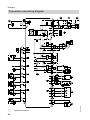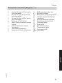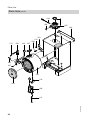
1
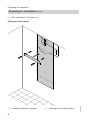
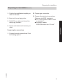
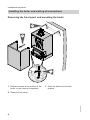
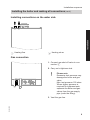
Installation and service
instructions
VIESMANN
for contractors
Vitodens 100-W
Type WB1B, 7.9 to 26.0 kW
Wall mounted gas fired condensing boiler
Natural gas and LPG version
Gas council no.: 41-819-21; 41-819-22; 41-819-23; 41-819-24
VITODENS 100-W
5368 662 GB
2/2009
Please keep safe.
Safety instructions
Safety instructions
Please follow these safety instructions closely to prevent accidents and material losses.
Safety instructions explained
Danger
This symbol warns against the
risk of injury.
!
Please note
This symbol warns against the
risk of material losses and environmental pollution.
Note
Details identified by the word "Note" contain additional information.
■ all current safety regulations as
defined by DIN, EN, DVGW, TRGI,
TRF, VDE and all locally applicable
standards,
■ Gas Safety (Installation & Use) Regulations
– the appropriate Building Regulation
either the Building regulations, the
Building Regulation (Scotland),
Building Regulations (Northern Ireland),
– the Water Fittings Regulation or
Water Bylaws in Scotland,
– the current I.E.E. Wiring Regulations.
Target group
If you smell gas
Regulations
Observe the following when working on
this system
■ all legal instructions regarding the prevention of accidents,
■ all legal instructions regarding environmental protection,
■ the Code of Practice of relevant trade
associations,
2
Danger
Escaping gas can lead to explosions which may result in serious
injury.
■ Never smoke. Prevent naked
flames and sparks. Never
switch lights or electrical appliances ON or OFF.
■ Close the gas shut-off valve.
■ Open windows and doors.
■ Remove all people from the
danger zone.
■ Notify your gas or electricity
supplier from outside the building.
■ Shut off the electricity supply to
the building from a safe place
(outside the building).
5368 662 GB
These instructions are exclusively
designed for qualified personnel.
■ Work on gas equipment must only be
carried out by a qualified gas fitter.
■ Work on electrical equipment must
only be carried out by a qualified electrician.
■ The system must be commissioned by
the system installer or a qualified person authorised by the installer.
Safety instructions
Safety instructions (cont.)
If you smell flue gas
Danger
Flue gas can lead to life-threatening poisoning.
■ Shut down the heating system.
■ Ventilate the boiler room.
■ Close all doors leading to the
living space.
Repair work
!
Please note
Repairing components which fulfil a safety function can compromise the safe operation of your
heating system.
Replace faulty components only
with original Viessmann spare
parts.
Working on the system
■ When using gas as fuel, also close the
main gas shut-off valve and safeguard
against unauthorised reopening.
■ Isolate the system from the power supply and check that it is no longer 'live',
e.g. by removing a separate fuse or by
means of a main isolator.
■ Safeguard the system against unauthorised reconnection.
Please note
Electronic modules can be damaged by electro-static discharges.
Touch earthed objects, such as
heating or water pipes, to discharge static loads.
!
Please note
Spare and wearing parts which
have not been tested together
with the heating system can compromise its function. Installing
non-authorised components and
non-approved modifications/conversion can compromise safety
and may invalidate our warranty.
For replacements, use only original spare parts from Viessmann
or those which are approved by
Viessmann.
5368 662 GB
!
Ancillary components, spare and
wearing parts
3
Index
Index
Installation instructions
Preparing for installation
Product information..............................................................................................
Preparing for installation.......................................................................................
5
5
Installation sequence
Installing the boiler and making all connections................................................... 8
Opening the control unit casing............................................................................ 11
Electrical connections........................................................................................... 12
Service instructions
Commissioning, inspection, maintenance
Steps - commissioning, inspection and maintenance.......................................... 15
Further details regarding the individual steps....................................................... 16
Troubleshooting
Function sequence and possible faults................................................................ 26
Fault messages on the display............................................................................. 27
Repairs................................................................................................................. 31
Gas type conversion
Converting from LPG to natural gas..................................................................... 37
Control unit
Functions and operating conditions in weather-compensated mode................... 39
Designs
Connection and wiring diagram............................................................................ 40
Parts lists............................................................................................................ 42
Specification....................................................................................................... 45
Certificates
Declaration of conformity...................................................................................... 46
5368 662 GB
Keyword index.................................................................................................... 47
4
Preparing for installation
Product information
Vitodens 100-W, WB1B
Set up for operation with natural gas.
Preparing for installation
Preparing the boiler installation
375
93
285
151
25
26
43
47
Installation
Dimensions and connections
600
A B
D
C
5368 662 GB
119
A Heating flow
B Heating return
123
C Condensate drain: Plastic pipe 7
22 mm
5
Preparing for installation
Preparing for installation (cont.)
D Gas connection, 1/2" male iron
Fitting the wall retainer
25
150
≥250
B
Ø1
0
A Vitodens installation template
6
B Opening for the balanced flue
5368 662 GB
A
Preparing for installation
Preparing for installation (cont.)
1. Position the installation template provided on the wall.
2. Mark out the rawl plug holes.
3. Drill 710 mm holes and insert the
rawl plugs provided.
2. Prepare gas connection.
3. Prepare the electrical connections.
Observe valid IEEE standards.
■ A 1.5 m long power cable is fitted
as standard.
■ Accessory cables:
NYM-O two-core min. 0.5 mm2.
Installation
4. Secure wall retainer with screws provided.
Preparing the connections
5368 662 GB
1. Prepare the water connections. Flush
the heating system.
7
Installation sequence
Installing the boiler and making all connections
Removing the front panel and mounting the boiler
3.
2.
1.
2x
1. Release screws at the bottom of the
boiler; do not remove completely.
3. Hook the boiler into the wall
retainer.
5368 662 GB
2. Remove front panel.
8
Installation sequence
Installing the boiler and making all connections (cont.)
Installing connections on the water side
Installation
A B
A Heating flow
B Heating return
Gas connection
1. Connect gas shut-off valve to connection A.
2. Carry out a tightness test.
!
A
Please note
Excessive test pressure may
damage the boiler and gas
valve.
Max. test pressure 150 mbar.
Where higher pressure is
required for tightness tests,
separate the boiler and gas
valves from the gas supply
pipe (undo the fitting).
5368 662 GB
3. Vent the gas line.
9
Installation sequence
Installing the boiler and making all connections (cont.)
Condensate connection
Connect condensate drain A with a
slope and pipe vent to the public sewer.
Observe the local waste water regulations.
Note
Fill the siphon with water before commissioning.
A
Filling the siphon with water
Fill the flue gas connection with a minimum of 0.3 l of water.
Please note
During commissioning, flue gas
may be emitted from the condensate drain.
Fill the siphon with water immediately prior to commissioning.
5368 662 GB
!
10
Installation sequence
Installing the boiler and making all connections (cont.)
Balanced flue connection
A
B
Connect the balanced flue.
During installation and positioning of the
flue system, observe building regulations part L, J and BS 5440 Part 1 and
2.
Installation
Flue system installation instructions.
A Flue gas
B Ventilation air
Opening the control unit casing
Please note
Electronic modules can be damaged by electrostatic discharge.
Before beginning work, touch earthed objects, such as heating or water pipes,
to discharge static loads.
5368 662 GB
!
11
Installation sequence
Opening the control unit casing (cont.)
2.
3.
1.
4x
Electrical connections
5368 662 GB
Information regarding the connection of accessories
For connection of accesseries, observe the separate installation instructions
provided with the accessories.
12
Installation sequence
Electrical connections (cont.)
X7
GAS
FAN
?LN 1 LN
X20
B
PUMP
5
D
X1
E F
Installation
X21
4 3 2 1
C
A
Note
Pump can be connected externally of the
boiler through the external terminal box
A Only for weather-compensated
mode:
Outside temperature sensor (accessory)
B Lead (accessory)
C Terminal box cylinder demand
(accessory; see separate installation instructions)
D Jumper (remove when connecting a
room thermostat or switched live for
'Y' or 'S' Plan installation)
E Power supply (230 V, 50 Hz).
Danger
Incorrect wire allocation can
cause severe injuries and
damage to the equipment.
Take care not to interchange
wires "L1" and "N".
The power supply must be equipped
with a neutral conductor. Water
pipes should be connected to the
earth bonding of the house in question.
F Vitotrol 100 (room thermostat) or onsite room temperature controller
5368 662 GB
Separate installation instructions
or
Input for Y-plan or S-plan heating
systems
13
Installation sequence
Electrical connections (cont.)
Outside temperature sensor (accessory)
1. Plug the lead supplied with the outside temperature sensor into socket
"X21".
2. Connect the outside temperature
sensor to terminals 3 and 4.
Routing leads and closing control unit casing
!
Please note
Leads will be damaged if they come into contact with hot parts.
When routing and securing leads on site, ensure that the maximum permissible temperatures for these cables are not exceeded.
3.
1.
5368 662 GB
2.
14
Commissioning, inspection, maintenance
Steps - commissioning, inspection and maintenance
For further information regarding the individual steps, see the page indicated
Commissioning steps
Inspection steps
Maintenance steps
•
•
•
•
1. Filling the heating system.............................................. 16
2. Converting to operation with LPG................................ 16
3. Checking the CO2 or O2 content.................................... 18
•
•
•
•
4. Burner removal .............................................................. 20
•
•
•
•
•
•
6. Checking and adjusting electrodes.............................. 22
•
•
9. Burner installation ......................................................... 24
•
•
•
•
•
•
•
•
•
11. Checking electrical connections for tightness
•
•
13. Fitting the front panel..................................................... 25
7. Cleaning the heat exchanger......................................... 22
8. Checking the condensate drain and cleaning the
siphon.............................................................................. 23
10. Checking all connections on the heating water side
and DHW side for leaks
12. Checking gas equipment for tightness at operating
pressure .......................................................................... 25
14. Instructing the system user........................................... 25
5368 662 GB
•
5. Checking the burner gasket and the burner gauze
assembly......................................................................... 21
15
Service
•
•
•
Page
Commissioning, inspection, maintenance
Further details regarding the individual steps
Filling the heating system
!
Please note
Unsuitable fill water increases the level of deposits and corrosion and may
lead to boiler damage.
■ Thoroughly flush the heating system prior to filling it with water.
■ Only use fill water of potable quality.
■ Soften fill water harder than 300 ppm.
■ An antifreeze additive suitable for heating systems can be mixed with the
fill water.
Fill and vent heating system.
Converting to operation with LPG
In the delivered condition, the boiler is
set up for operation with natural gas. For
operation with LPG, the gas nozzle must
be changed and the gas type converted
in the control unit.
Changing from LPG to natural gas - see
page 37.
5368 662 GB
Separate installation instructions.
16
Commissioning, inspection, maintenance
Further details regarding the individual steps (cont.)
10 -1
+2
Checking and adjusting the ignition and ionisation electrodes
0,5
5+
Check all clearances. If the gaps are not
as specified or the electrode is damaged,
replace and align the electrode together
with new gaskets. Tighten the electrode
fixing screws. (2.5 Nm approx.).
5368 662 GB
Check the electrode for wear and contamination
Clean the electrode with a small brush
(not with a wire brush) or emery paper.
17
Service
A Ignition and ionisation electrode
Commissioning, inspection, maintenance
Further details regarding the individual steps (cont.)
Checking the CO2 or O2 content
Vitodens 100-W is factory-set for natural
gas. During commissioning or maintenance, the CO2 and CO have to be
measured at the boiler flue adaptor test
point to check the flue integrity. Subject
to the Wobbe index, the CO2 content
fluctuates between 7.4 % and 10.5 %.
And CO of up to 500 ppm is acceptable.
We recommend to measure O2 as the
value is unmistakable regarding lambda
(air/gas). The O2-content fluctuates
between 7.5 % and 3.2 %. Or alternatively CO/CO2 ratio has to be less than
0.004.
If the actual CO2 or O2 and CO values
deviate from the stated range, check the
balanced flue systems for leaks. If flue
installation is o.k., change the gas
valve.
1. Connect a flue gas analyser at flue
gas port A on the boiler flue connection.
2. Start the boiler.
A
3. Turn rotary selector "tr" clockwise
for less than 2 s and then anticlockwise back to the control range on the
right.
The display shows "SERV" and the
boiler water temperature is shown.
5368 662 GB
r
18
Commissioning, inspection, maintenance
Further details regarding the individual steps (cont.)
4. Adjust the upper output:
Turn rotary selector "tr" to the control range on the right.
The display shows 5 bars for upper
output.
5. Measure the CO2 content for upper
output.
The CO2 content must be between
7.4 and 10.5 %.
6. Adjust the lower output:
Turn rotary selector "tr" to the left
control range.
The display shows 1 bar for lower
output.
7. Test the CO2 content for lower output.
The CO2 content must be between
7.4 and 10.5 %.
5368 662 GB
9. Shut the boiler down, remove flue gas
analyser and close flue gas port A.
19
Service
8. If the CO2 content is not within the
given range, check the flue gas/ventilation air system for tightness.
Remedy any leaks.
Commissioning, inspection, maintenance
Further details regarding the individual steps (cont.)
Burner removal
4x E
C B
A
D
1. Switch OFF the power.
6. Disconnect gas supply pipe D fitting.
2. Shut off the gas supply.
3. Disconnect electrical cables from fan
motor A, gas valve B.
4. Open control unit casing (see
page 11) and pull out the lead to ignition electrode C.
7. Undo four screws E and remove the
burner.
!
Please note
To prevent damage,
never rest the burner on the
gauze assembly.
5368 662 GB
5. Disconnect the venturi extension
from fan A.
20
Commissioning, inspection, maintenance
Further details regarding the individual steps (cont.)
Checking the burner gasket and the burner gauze assembly
Check burner gasket A for damage and replace if required.
Replace the burner gauze assembly if it is damaged.
E
D
C
A
4x
B
2. Undo the three cheese-head screws
and remove thermal insulation ring
C.
5. Refit thermal insulation ring C.
Fixing screw torque: 3.5 Nm.
6. Refit electrode B.
Fixing screw torque: 3.5 Nm.
Service
1. Remove electrode B.
5368 662 GB
3. Undo four Torx screws and remove
burner gauze assembly D with its
gasket E.
4. Insert and secure a new burner
gauze assembly D with a new gasket E.
Fixing screw torque: 3.5 Nm.
21
Commissioning, inspection, maintenance
Further details regarding the individual steps (cont.)
Checking and adjusting electrodes
1. Check the electrode for wear and
contamination.
2. Clean the electrode with a small
brush (not with a wire brush) or emery
paper.
8+2
3. Check the electrode gaps. If the gaps
are not as specified or the electrode
is damaged, replace and align the
electrode together with a new gasket.
Tighten the electrode fixing screws
with 3.5 Nm.
4+0,5
Cleaning the heat exchanger
Please note
Scratches on parts that come into contact with flue gas can lead to corrosion.
Never use brushes to clean the heat exchanger.
5368 662 GB
!
22
Commissioning, inspection, maintenance
Further details regarding the individual steps (cont.)
1. Use a vacuum cleaner to remove residues from heat exchanger A inside
the combustion chamber.
2. If required, spray slightly acidic,
chloride-free cleaning agents based
on phosphoric acid onto heat
exchanger A and let the solution
soak in for approx. 20 min.
3. Thoroughly flush heat exchanger A
with water.
A
Checking the condensate drain and cleaning the siphon
1. Check at siphon A that the condensate can drain freely.
2. Place an appropriate container under
siphon A.
B A
4. Replace locking cap B with gasket.
5368 662 GB
5. Fill siphon A with water by pouring
about 0.3 l of water into the combustion chamber.
23
Service
3. Remove locking cap B and drain the
contents of siphon A into the container.
Commissioning, inspection, maintenance
Further details regarding the individual steps (cont.)
Burner installation
E D
C
B
1. Fit the burner and torque screws A
diagonally with 4.0 Nm.
6. Reopen gas supply and switch on
power supply.
2. Insert new gasket and tighten the fittings on gas supply pipe B.
7. Check the gas connections for tightness.
3. Push the venturi extension on to fan
C.
Danger
Escaping gas leads to a risk of
explosion.
Check all fittings for gas tightness.
4. Attach electrical cables to fan motor
C and gas valve D.
5. Push ignition electrode cable E into
the control unit and close the control
unit casing.
24
5368 662 GB
4x A
Commissioning, inspection, maintenance
Further details regarding the individual steps (cont.)
Checking gas equipment for tightness at operating pressure
Danger
Escaping gas leads to a risk of
explosion.
Check gas equipment for tightness.
Fitting the front panel
3.
2.
1.
Service
4.
2x
Instructing the system user
5368 662 GB
The system installer must hand the operating instructions to the system user and
instruct him/her in the operation of the system.
25
Troubleshooting
Function sequence and possible faults
Display
no
Control unit issues
a heat demand
Measures
Increase set value
and ensure heat is
drawn off
yes
Fan starts
no
After approx. 51 s
fault F9
Check fan, fan
connecting cables,
power to the fan
and fan control
no
Fault F4
Check connection
to ignition module
no
Fault F4
Check gas train
(control voltage
230 V); check gas
supply pressure
no
Fault F4
Measure ionisation current, check
electrode adjustment and gas line
for airlocks.
Stops below the set
boiler water temperature and
restarts immediately
Check flue system
for tightness (flue
gas recirculation),
check gas flow
pressure
yes
Ignition
yes
Gas train opens
yes
Ionisation current
builds (higher than
2 µA)
Symbol A
yes
no
5368 662 GB
Burner in operation
26
Troubleshooting
Fault messages on the display
Fault code
on display
10
18
30
38
50
58
60
68
5368 662 GB
A9
System characteris- Cause
tics
Constant mode
Short circuit, outside temperature
sensor
Constant mode
Outside temperature sensor lead
broken
Burner switched off
Short circuit, boiler
water temperature
sensor
Burner switched off
Boiler water temperature sensor
lead broken
No DHW heating
Terminal box cylinder demand fault
Measures
Check outside temperature sensor and lead (see
page 31).
Check outside temperature sensor and lead (see
page 31).
Check boiler water temperature sensor (see
page 33).
Check boiler water temperature sensor (see
page 33).
Check terminal box connections and replace terminal box if required.
No DHW heating
Terminal box cylin- Check terminal box conder demand fault
nections and replace terminal box if required.
Burner switched off
Short circuit, return Check return temperature
temperature sensensor (see page 33).
sor
Burner switched off
Return temperaCheck return temperature
ture sensor lead
sensor (see page 33).
broken
Control mode without Communication
Check connections and
Open Therm device fault Open Therm lead; replace Open Therm
device
device if required.
27
Service
f2
Faults are indicated by a flashing fault
code with fault symbol "U" on the display.
For fault code explanations see the following table.
■ Flashing fault symbol "U": To reset
press "U RESET" (see page 30) after
the fault has been remedied
■ Constantly displayed fault symbol "U":
Will automatically reset after the fault
is remedied
Troubleshooting
Fault messages on the display (cont.)
Fault code
on display
b0
b8
E5
System characteris- Cause
tics
Burner switched off
Short circuit, flue
gas temperature
sensor
Burner switched off
Flue gas temperature sensor lead
broken
Burner switched off
Internal fault
Burner switched off
Burner in a fault
state
F2
Burner in a fault
state
F3
Burner in a fault
state
F4
Burner in a fault
state
Check sensor (see
page 34).
Check sensor (see
page 34).
Check ionisation electrode and connecting
leads.
Press "Reset" (see
page 30).
Internal fault
Replace control unit.
Max. flue gas tem- Check heating system fill
perature exceeded level. Check circulation
pump. Vent system.
Press "Reset" (see
page 30).
Temperature limCheck heating system fill
iter has responded level. Check circulation
pump. Vent system.
Check temperature limiter
and connecting leads.
Press "Reset" (see
page 30).
Flame signal is
Check ionisation elecalready present at trode and connecting
burner start
lead.
Press "Reset" (see
page 30).
No flame signal is Check ignition/ionisation
present
electrode and connecting
leads, check gas pressure, check gas train, ignition, ignition module and
condensate drain.
Press "Reset" (see
page 30).
5368 662 GB
F0
F1
Measures
28
Troubleshooting
Fault messages on the display (cont.)
System characteris- Cause
tics
Burner in a fault
Fuel valve closes
state
too late
F9
Burner in a fault
state
Fan speed too low
during burner start
FA
Burner in a fault
state
Fan not at standstill
FC
Burner blocked
Electrical fan control (control unit)
faulty
Fd
Burner blocked
Burner control unit
fault
FF
Burner blocked
Burner control unit
fault
Measures
Check gas train. Check
both control paths.
Press "Reset" (see
page 30).
Check fan, check fan connecting cables and power
supply, check fan control.
Press "Reset" (see
page 30).
Check fan, fan connecting
cables and fan control.
Press "Reset" (see
page 30).
Check fan connecting
cables and replace if
required, or replace control unit
Check ignition electrodes
and connecting cables.
Check whether a strong
interference (EMC) field
exists near the appliance.
Press "Reset" (see
page 30).
Replace control unit if
fault persists.
Check ignition electrodes
and connecting cables.
Check whether a strong
interference (EMC) field
exists near the appliance.
5368 662 GB
Press "Reset" (see
page 30).
Replace control unit if
fault persists.
29
Service
Fault code
on display
F8
Troubleshooting
Fault messages on the display (cont.)
Press reset
Note
Only press RESET if fault symbol "U" is flashing.
Turn rotary selector "rt" to "U
RESET" in under 2 s, then back to the
control range.
5368 662 GB
r
30
Troubleshooting
Repairs
Removing front panel and pivoting control unit downwards
2.
3.
4.
1.
2x
Service
Outside temperature sensor
5368 662 GB
Note
The outside temperature sensor can
only be connected if
a) the boiler does heating only
b) the boiler serves heating and hot
water a separate switched live connection from the DHW programmer has to
be connected to the boiler (see separate
instructions control box)
31
Troubleshooting
Repairs (cont.)
1. Open the control unit casing. See
page 11.
2. Disconnect outside temperature sensor leads.
X21
X7
X20
4 3 2 1
20
3. Check the sensor resistance and
compare it with the curve.
4. Replace the sensor if the resistance
varies significantly from the figure
shown.
10
8
6
4
-15 -5 0 10 20 30
-10
Temperature in °C
5368 662 GB
Resistance in kΩ
100
80
60
40
32
Troubleshooting
Repairs (cont.)
Checking the boiler water temperature sensor and return temperature sensor
B
5368 662 GB
1. Pull the leads from boiler water temperature sensor A or return temperature sensor B and check the resistance.
33
Service
A
Troubleshooting
Repairs (cont.)
Resistance in kΩ
20
2. Check the sensor resistance and
compare it with the curve.
10
8
6
4
3. If the resistance varies significantly
from the figure shown, drain boiler on
the heating water side and replace
the sensor.
2
1
0.8
0.6
0.4
10 30 50 70 90 110
Temperature in °C
Danger
The boiler water temperature
sensor is immersed in the
heating water (risk of scalding).
Drain the boiler before replacing the sensor.
Checking the flue gas temperature sensor
5368 662 GB
A
1. Pull the leads from flue gas temperature sensor A and check the resistance.
34
Troubleshooting
Repairs (cont.)
Resistance in kΩ
20
2. Check the sensor resistance and
compare it with the curve.
10
8
6
4
3. Replace the sensor if the resistance
varies significantly from the figure
shown.
2
1
0.8
0.6
0.4
10 30 50 70 90 110
Temperature in °C
Checking the temperature limiter
If the burner control unit cannot be reset after a fault shutdown, although the boiler
water temperature is below approx. 95 °C, check the temperature limiter.
1. Pull the leads from temperature limiter A.
2. Check the continuity of the temperature limiter with a multimeter.
3. Remove the faulty temperature limiter.
5. Press "Reset" on the control unit (see
page 30).
5368 662 GB
A
35
Service
4. Install a new temperature limiter.
Troubleshooting
Repairs (cont.)
Checking the fuse
F4
1. Switch OFF the power.
3. Check fuse F4.
5368 662 GB
2. Open control unit casing (see
page 11).
36
Gas type conversion
Converting from LPG to natural gas
Removing gas restrictor
A
D
C
B
1. Remove the burner (see page 20).
2. Undo three screws A and remove
gas train B.
3. Remove gas restrictor C (if fitted)
from gas train B and insert new gas
restrictor C into gas train B.
4. Fit gas train B with a new gasket
D.
Fixing screw torque A: 3 Nm.
5. Refit the burner with a new gasket
E.
Union nut torque: 22 Nm.
5368 662 GB
Converting gas type on the control unit
1. Turn ON/OFF switch ON.
37
Service
E
Gas type conversion
Converting from LPG to natural gas (cont.)
2. Simultaneously turn rotary selectors
"à" and "tr" to their central position.
"SERV" appears on the display.
r
3. Turn rotary selector "tr" anticlockwise as far as it will go within 2 s.
"A" Appears on the display and the
set value flashes.
r
4. Adjust the control unit to natural gas
or LPG by turning the left rotary selector "à".
The display shows:
■ "0" for operation with natural gas
or
■ "1" for operation with LPG.
5. Do not adjust the rotary selectors for
15 s. The set operating mode is then
saved and the control unit returns to
standard mode.
6. Switch ON/OFF switch off and on
again. The selected gas type is now
enabled
Checking the CO2 content
5368 662 GB
See page 18.
38
Control unit
Functions and operating conditions in weather-compensated mode
In weather-compensated mode, the
boiler water temperature is regulated
subject to the outside temperature.
Heating curve of weather-compensated control unit
90
G
80
F
Boiler water or
flow temperature in °C
70
E
D
60
C
50
B
40
A
30
20
10
0
20 15
10
5
0
-5
-10 -15 -20
Rotary selector setting "tr"
A =1
B =2
C =3
D =4
E = Delivered condition
F =5
G =6
If the boiler temperature is less than 8C
the circulating pump is ON and at a boiler
temperature of 12C the pump is OFF.
The burner will be switched on at a boiler
temperature of 5°C and switched off at
15°C.
Frost protection function
5368 662 GB
The frost protection is generally active
when the boiler is in 'Stand-by' mode.
39
Service
Outside temperature in °C
Designs
A
40
Ignition/ionisation
5368 662 GB
Connection and wiring diagram
Designs
Connection and wiring diagram (cont.)
B
C
D
E
F
G
L
X ...
§
%
PCB inside the control unit
Electrical interface
Boiler water temperature sensor
Cylinder demand terminal box
(accessory)
Flue gas temperature sensor
aG
Return temperature sensor
aJ
Circulation pump
sÖ
Flow switch
dD
Gas solenoid valve
dG
Temperature limiter
fJ
a-Ö Fan motor 230 V~
a-ÖA Fan control
5368 662 GB
Service
H
K
Vitotrol 100, type UTA or on-site
room thermostat
Vitotrol 100, type RT or on-site
room thermostat
Vitotrol 100, type UTD or on-site
room thermostat
Mains input 230 V/50 Hz
Open Therm connection (remote
control)
Outside temperature sensor
(accessory)
Time switch (accessory)
Gas pressure limiter (accessory)
41
Parts lists
Parts lists
When ordering spare parts:
Quote the part and serial no. (see type
plate) and the item number of the
required part (as per this parts list).
Obtain standard parts from your local
supplier.
Burner door
Venturi extension
Control unit
Terminal box cover
Thermocouple
Boiler water temperature sensor
Flow control switch
Fuse 2.5 A (slow) (10 pce.)
Wall retainer
Front panel
Flue gas temperature sensor
Wearing parts
018 Ignition and ionisation electrode
Parts not shown
023 Conversion kit G 31
030 Gas solenoid valve cable harness
35
031 Fan cable harness 100
032 Cable harness X20
033 Power cable, auxiliary earth
035 Cable fixing
036 Spray paint, Vitowhite
037 Touch-up paint stick, Vitowhite
038 Special grease
041 Installation and service instructions
042 Operating instructions
A Type plate
5368 662 GB
001 Heat exchanger
002 Heating water flow connection pipe
003 Heating water return connection
pipe
004 Gas supply pipe
005 Boiler flue connection
006 Siphon
007 Flue gas gasket
008 Boiler flue connection plug
009 Thermal insulation block
010 Condensate pipe
011 Condensate hose
012 Fixing clips
013 Clip Ø 8 (5 pce.)
014 Burner gasket
015 Thermal insulation ring
016 Burner gauze assembly
017 Burner gauze assembly gasket
019 Gasket, ignition and ionisation
electrode (5 pce.)
020 Fan
021 Gas valve
022
024
025
026
027
028
029
034
039
040
043
42
Parts lists
Parts lists (cont.)
017
022
019
024
018
014
015
016
004
040
012
021
020
026
034
VI
ES
Service
025
MA
5368 662 GB
NN
43
Parts lists
Parts lists (cont.)
043
008
005
039
A
028
013
029
002
013
003
007
028
027
001
010
009
006
5368 662 GB
011
44
Specification
Specification
Rated voltage:
Rated frequency:
Rated current:
Safety class:
Protection:
230 V~
50 Hz
2.0 A~
I
IP X4 to EN 60529
Temperature limiter
setting:
Line fuse (mains):
100 °C (fixed)
max. 16 A
Permissible ambient temperature
■ During operation:
0 to +40 °C
During storage
■ and transport:
-20 to +65 °C
Gas fired condensing boilers, class II 2H3P
Rated output range
TV/TR 50/30 °C
kW
7.9 - 13
7.9 - 16
kW
7.2 - 11.9
7.2 - 14.6
TV/TR 80/60 °C
Rated thermal load
range
Connection values *1
relative to the max.
load with
Natural gas H
LPG P
Power consumption
(max.)
Weight without front
panel (installation)
Product ID
kW
7.9 - 19
7.2 - 17.3
7.9 - 26
7.2 - 23.7
7.4 - 12.2
7.4 - 15.0
7.4 - 17.8
7.4 - 24.3
m3/h
kg/h
W
1.3
0.9
45
1.6
1.1
50
1.9
1.4
55
2.6
1.9
60
kg
24
24
24
24
Min. throughput: 200 l/h
Service
Min. static pressure: 0,2 bar
_-0085 BT 0029
5368 662 GB
*1
The connection values are only for documentation purposes (e.g. in the gas contract application) or to estimate the supplementary volumetric settings. Because of
factory settings, the gas pressure must not be altered from these settings. Reference: 15 °C, 1013 mbar.
45
Certificates
Declaration of conformity
Declaration of conformity for the Vitodens 100-W
We, Viessmann Werke GmbH & Co KG, D-35107 Allendorf, confirm as sole responsible body that the product Vitodens 100-W complies with the following standards:
DIN 4702–6
EN 483
EN 625
EN 677
EN 50 165
EN 55 014
EN 60 335
EN 61 000-3-2
EN 61 000-3-3
In accordance with the following directives, this product is designated _-0085:
90/396/EEC
92/ 42/EEC
2004/108/EC
2006/95/EC
This product complies with the requirements of the Efficiency Directive
(92/42/EEC) for condensing boilers.
Allendorf, 4 February 2009
Viessmann Werke GmbH&Co KG
5368 662 GB
pp. Manfred Sommer
46
Keyword index
Keyword index
B
Boiler water temperature sensor........33
Burner gasket.....................................21
Burner gauze assembly.....................21
Burner installation..............................24
Burner removal..................................20
C
Cleaning the combustion chamber....22
Cleaning the heat exchanger.............22
Commissioning..................................16
Condensate connection.....................10
Condensate drain...............................23
Connection diagram...........................40
Connections.........................................9
Connections on the water side.............9
D
Declaration of Conformity..................46
E
Electrical connections........................12
F
Fault code..........................................27
Fault messages..................................27
Filling function....................................16
Filling the system...............................16
Flue gas temperature sensor.............34
Flue pipe............................................11
Frost protection..................................39
Function sequence.............................26
Fuse...................................................36
H
Heating curve.....................................39
I
Ignition...............................................22
Ignition electrode..........................17, 22
Ionisation electrode............................22
O
Opening the control unit casing.........11
Outside temperature sensor .............31
R
Reset..................................................30
S
Safety chain ......................................35
Siphon..........................................10, 23
Spare parts........................................42
Specification ......................................45
T
Temperature limiter............................35
Troubleshooting.................................31
V
Ventilation air pipe.............................11
W
Wall mounting......................................6
Weather-compensated mode.............39
5368 662 GB
G
Gas connection....................................9
Gas type conversion
37
■ LPG................................................16
■ Natural gas.....................................37
47
Subject to technical modifications.
chlorine-free bleached paper
Printed on environmentally friendly,
48
Viessmann Limited
Hortonwood 30, Telford
Shropshire, TF1 7YP, GB
Telephone: +44 1952 675000
Fax: +44 1952 675040
E-mail: [email protected]
5368 662 GB
Viessmann Werke GmbH&Co KG
D-35107 Allendorf
Telephone: +49 6452 70-0
Fax: +49 6452 70-2780
www.viessmann.com