1
lsears I
CHAIN SAW
owner's
manual
MODEL
NO.
358.352030-10""
358.352060-12"
358.352070-14"
CRRFTSMRtl
2.0/'i0"
CAUTION:
Read Rules for
Safe Operation
and Instructions
2.0/'I2"
2.0/14
• Assembly
• Maintenance
* Operation
* Repair
Parts
i
Record in the space provided below the Made--and
of your saw. These numbers are located on the starting
decal.
Model
No.
Serial
Serial No.
instructions
No.
Carefully
Retain these numbers
Sears,
63869
9/_0
Roebuck
and
Co.,
for future
Chicago,
reference.
Il!.
60684
pRiNTED
U.SJ_.
iN U. _. A-
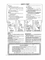
-SAFETY RRST
Y
0
DON'T
O
Don't
O
Don't
start cutting until
you llave a clear work area,
secure tooting,
and a planned retreat from
a falling
tree.
use the saw when you
O
Don't
O
Don't touch
O
Don't use the s_w in an er_lor, ed _ea
tL_
are tired
V
a saw t.hat is damaged
a moving
or poorly,
adjssted
_-t=a_n
out
of
the
work
area when
the saw
is
BE CAREFUL
O
Oon't climb in a tree with
Get professional
help.
a saw -
it is very dangerous.
0
Be caref_l.;¢utting
small braneh_s end b_hes -- smelt
limbs may catch the chain and be whipped toward you.
II LOOK OUT FOR KICKBACK
_VD_O
O
Wear safe footwear,
sr_ug_fitting
ing, and head protection
0
Be careful handling fuel
with
Keep others
running
ClOthing,
When. the moving cha!n at the nose of the bar touches
an object, the bar and _ain
can be thrown
Upward
with considerable for_'e. This is KICKBACK!
0
Hold the saw firmly
O
Don't
and eye, hear-
O
Hold the saw firmly
O
Carry the saw with the engine stopped,
the bar and
_haln to the rear, and the muffler away/from
you
both hands
0
Shat off the engine before
0
Keep the handles free of oil and rue!
setting
O
O Don't
it down
both
han_ls
_et the nose of the bar _ontact
O Cut Only
a log, brar_h,
etc.
at h_gh engine speeds
O
Don't reach above shoulder height to cut -- the chain is
too close to your face in this position
O
Keep your
.
THE SAW WHEN
IT NEEDS REPAIR
with
overreach
chain sharp
NEVER USE THE SAW |
WHEN TIRED
|
USE BOTH HANDS
WHEN OPERATING
GENERAL TIPS
Dress
Safely
-- Loose clothing
may
get caught
in moving
parts.
Woo_
it's_
One Man Job -_ Keep others out of the work area when the
er_gine is P.Jnn[r_j.
LOOK OUT"F_R
KICKBACK"
-- Don*t let the
touch anything
while l_e engine is running:
T_
_
Of year saw
. .
I_ep
the (T_ain. Out of the Dirt -'E_
on-the !'og_/iil dull the chain quickly,
Keep the _J_air_ Sharp -- A dull chain
excessive weartootherpart_,
Don't
Force the
. crowbar.
Saw Out
Or another
saw
is unsafe
o
bar
_f I_r-_rt
and wilt c_use
Use a wedge,
an axe,
Tell
You
A
Lot
--
The dl[ps
should
a
Performance
and Safety
--
Keep your saw running
well and your
WOrk wlti be easier and safer.
_-
For 90 days from date of purchase, Se,ars will "repair any defect in material or workmanship-in this ga_oliniechain saw a_ no charge.
If the chain saw is used for commercial or renta! purposes, the warranty applies for
only 30 days from the date of purchase.
service
the
like, your
. Out .Ol_
At H_gh .SPeeds -- Keep t/le tttrettfe-wi_e
open when
cutting.
Don't
run the engine at high speed when not cutting!
It _hould Cut Smoothly
-- If the engine stalls or bogs with light
pressure, check the carburetor
setting
and the a_r filter.
FULL 90 DAY WARRANTY
Warranty
be about
Don't Press Hard -- Light pressure is ervaugh.'Heavy
pressure ¢an
cause un,_afe _ondi_iom%
Check for a &-.a'g¢_ai_ Gr w_.
_.
_Sea Guide Bar Maintenance
and Chain _arpen_ngt,
force it out.
=
_
of the
,
a small _oo_t
of a Jam but don't
tip
Chil_
size of the chain teeth. If they are small and powder
chain is dull. Get it Sharpened !
is available
by
contacting
the
nearest
Sears
store
may
also
or Service
_
Center
throughout the United _ates.
This
which
warranty
vary
gives
from
state
you
specific
to state.
legal
rights,
and
you
have
other
rights
<:_
TABLE OF CONTENTS
• I'NSTALLING
THE BAR AND CHA! N ......................................................
FUEL AND OIL
.........
;............................................................
SAWING TECHNIQUES
................................................................
MAINTENANCE
.....................................................................
GUIDE BAR MAINTENANCE
............................................................
CHAIN SHARPENING
.................................................................
TEMPERATURE
LIMITING
MUFFLER
INSTRUCTIONS
_ee [mpo/taf)t
/_orJce on page 15 _egatding
states
4
5
5
7
8
................
.............
[equili[l_q temperature
I/miring
8
15
...........
ml_{e/"
¢ovsr,
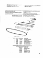
SPECIFICATIONS
358.352030
(2.0/10")
SPARK PLUG
SPARK PLUG GAP
MODULE AIR GAP
IGNITIONS,
358,352060
(2.0/12")
Champion CJ8
.023 to .027"
.
FUEL MIX
Gel. Reg. Gasoline
10 '_Non-Armor Tip
BAR
•
CHAIN
Low
MUFFLE R
Profile
..............
{ • _rk
.008 to .012'"
State
Pt_ Oil to
1
GUIDE
-Champ!on CJ8
.023 to .027"
......... ,,,,.008
to .012"
Solid
(16:1)
_
3/8
Pitch•
Arresting
Hand Guard
358.352070
(2,0/14")
Champion CJ8
.023 to ,027"
-
Solid State ...........,,,
(16:1)
½ Pt. Oil to
GaL Re_. Gasoline
12" Sprocket Nose
Low Profile 3/8 Pitch"
Chrome Cutters
I
Spark
Arresting
'.008'{o .b12';" '
,:
" .Solid State' ''"."
(16:1)
½ Pt. Oil to .......
Reg. Gasoline
I4" Sprocket Nose
_ Low Profile 3/8 Pitch
.......
1 Gal.
Chrome
Spark
Cutters
Arrestin_
.........
Choke Knob
OmOff Swhch
Guide Bar Nose
Chain
Throttle
Trigger
NO;
Model No.
Cap
Guide Bar
Handle
HAIkIDGUARD MOUNTING
HANDGUARDS
I}O NOTELIMINATE
THE
OF INJURY AS A.RF..SULT OF KICKBACK
CONTROL OF THE CHA!N SAW. HEAD
POSSIBIUTY
OR LOSS OF
OPERATING
INSTRUCTIONS
CA.REFULLY.
.1. A_mb[e
_he handguard to the bend _n the handlebar as
shown= Do not tighten the screws,
2. Make sure the handguard {s parallel to the handlebar.
Alternately
tighten each handguard'mounting
screw mainraining an even gap between the handguard and mounting
;cap.
3. Tighten the mounting screws until the handguard and"
mounting cap are puFled together.
Caution: Screws
breakage.
must
be
tightened
evenly
to
prevent
INSTRUCTIONS
CAP
HANDGUARD"
INSTALLING
THE
BAR AND CHAIN
_r Always wear gloves when handling the chain!
It is sharp!
1.
Remove the bar clamp nut and rear bar clamp screw
(FigUre !}. Turn the adjusting screw, setting the pin all
the way to the rear (See Figure 5).
2.
Place the guide bar slot over the mounting
to the rear (Figure 2).
3.
Fit the chain over the clutch aod onto the guide
sure the cutters face the way shown in Figure 3.
4.
Slide the bar forward placing the adjusting
pin into the
hole in the bar (Figure 4). The pin can be moved farther
back by
turning
the
adjusting
screw
(Figure
5)
counterclockwise,
5.
Replace
FINGER
Rear Bar Clamp_
Screw
J
Figure
I
• 6.
7.
the bar clamp and tighten
TIGHT.
NOTE: Be sure fuel
Figure 1).
the
line is in slot in fan
pins and slide it
bar. Be
bar clamp nut
housing.
(See
Holding the tip of the bar up (Figure 5) turn the adjusting
screw clockwise 41_
until the chain is snug on the bar.
8. Lift
the chain from the bar near the middle of the bar
(Figure 6}. When tensioned right, the chain wilt lift about
1/8" from the bar. Figure 6 shows the right tension.
Adjust y<_ur chain until it looks like this.
g.
10.
Figure 2
Figure
Figure
3
4
Hold the bar tip up and _ighten the bar clamp nutfirmly.
Replace the rear housing screw. (See that fuel line is not
pind_ed and is in slot in fan housing).
The chain should not sag below the bar and should
freely around the bar.
move
CHAIN
STRETCHES
TENSION OFTEN!
THE
WHEN
Figure 5
Figure 6
USED.
CHEdK
OPERATING
INSTRUCTIONS
Before
Starting
3.
Hold the rear handle in your
trigger.
O Are the handles clean of gas and oil?
4.
Hold the starter handle in your left hand,
O D_d you fill the fuel AND oil tan_.s?
5.
Push the saw away from you while pulling the starter
quickly.
HOLD THE SAW FIRMLY'. Do not let the starter snap
back. Hold the handle end let the rope r_owind slowly.
6.
After
7.
Return the choke to its original position.
8.
Pull until the engine star_s• Allow 8 to 10 pulls for a new
unit or one which has been stored for time.
O Check the chain tension. Is the chain sharp?
FUEL and OIL
Fuel Mix: T6 parts gasoline to I part oil (T/2 pint oi! to one
gallon gasoline). Use air cooled two cycle engine oil for fuel
mix.
CAUTION:
When preparing fuel mixture, mix only the amount needed for
the job you are to do. Do not use fuel mixture that has been
stored longer than two (2) months. Fuel mixture stored longer
than this wilt cause hard starting and poor performance of
your saw. If fuel mix has been stored in your saw longer than
this _ime it should also be removed and filled with a fresh
mixture before using•
Chain Oil:
For cold weatl_er operation, above 30 ° F, use
straight Craftsman Bar and (;hain Lubricant. 30 ° to 0°, use 5%
diesel fuel #1 or kerosene and 95% Lubricant;
below 0°F,
use 10% diesel fuel #1 or kerosene and 90% LubdcanL If Bar
and Chain Lubricant is not diluted adequately,
the oil system
of the chain saw will not pump enough oil for adequate lubrication
of Bar and _'-_=ain .
a few pulls, the engine wilt fire.
The chain must not
maintenance section.
9.
10.
right hand and squeeze the
move
when the engine
idles• See
ff engine does not fire after 5 to 6 pulls, it may be flooded.
Push choke off (clockwise|
and pull starter several times
while holding trigger at wide open throttle.
If saw has run
out of fuel, 8 to 10 pulls with choke on may be required
to restart engine. When restarting a hot ,engine, or one
which has just been refueled, you may have to choke the
engine for one or two pufl_
To stop engine, push switch to "off" position. The engine
may also be stopped by pushing the choke lever to the
right (COu_ter-clockwise).
A WORD ABOUT CHAIN OILING
1• Fill the oil tank each time you fill the fuel tank. Lack of
oil onthe chain will quickly ruin the bar and chain.
2.
You will use at least 1/3 tank of oil for each tank of gas. If
you use less, check for a plugged oil hole in the guide bar.
•Use clean oil. Do not let sawdust or dirt
into the oil tank.
Clean the oil cap and the area around it before removing.
The oil tank is pressurized for pump operation• A little oil
will pump out after the engine stops. Oil on the bar and
chain will drip off after use. Let the saw stand and cool
off:Wipe
the bottom clean before storing•
STARTING
Move bystanders and obstructions
the trigger after the engine starts.
welt out of reach! Release
1.
Move the choke knob as far as itwil]
the arrow.
2.
Turn the switch On (to the left|,
CUTTING
go in the direction of
Push the saw away from
you while puUin9 the starter quickly•
TIPS
_1r Read the safety tips in the front
keep your chain sharp.
of this manual. Always
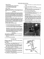
Plan Ahead
Check The Wind -- If it is strong enough to move the top of
the tree, DON • T CUT. 1 Come back another day!
Check The Lean-Tie
a weight to a
. tong. Hang the weight in your
good Verticat llne to help you
The tree wilt try to fall the way
Check
The Weight
with
Trim
Distribution
the most limbs, tt wil!
a few limbs to "balance"
piece of string about 3 feet
line of sight. The string is a
judge the lean of the tree.
it is leaning.
-- A tr_e is heavier on the side
try to f_l.l on its heavy side.
the t#ee.
Clear The Work Area -- You need a clean ar_a at! around the
tree for good footing. Get everything out of the area where
the tree will fall People, pets, cars, e_tc.
Find
2
a Retreat Path - Know which way you
the tree starts to fail. I_ake sure it is€lear.
Direction of Fall
are going when
5
FELLING
A
Direction
of
(Cutting down a tree)
Small Trees -
Less than 8- across
1. If
there is doubt about
"notch"
method described
Fall
B
the direction
_ B,
of
fall,
2.
Make a single felling cut or} the side away from
direction of fall. Don't cut all the way through!
3.
When the tree starts to fall, put the saw down
AWAY OUtCKLY!
L_ge Tr_s
1.
and GET
The tree will try to fall
2., Make the bottom notch cut first,.about
into the tree.
1/3 to 1/2 way
3.
Complete the notch with the slant
wedge of wood before going on.
4,
The felling cut is next. Make it on the side opposite
notch,
5.
It is made 2" higher than the bottom
7.
the
-- 8" or large r across
The notch is very impOrtant.
"into"
the notch,
6..DO
use
cut. Remove the
the
of the notch_
NOT try to cut through to the notch.
As the tree starts to fall, put the saw down and GET
AWAY QU ICK LY!
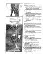
BUCKING
Bucking
is the sewing of a log or fallen
tree into smaller pieces.
F1 Use Both Hands --. grip the saw firmly with the thumb and
forefinger wrapped around the handte.
[3 S_and Uphill -- a fog that is cut loose will roll downhill
_] Keep The Chain Out Of The Dirt -- dirt will du II the chain.
A dutl chain is unsafe.
17 Stand to the left of the saw.
How To
A
tn area "'A", come up from the bottom
Finish by coming down from the top.
1/3 of the way.
B
In area °'B", come down from the top
Finish by coming up from the bottom.
1/3 of the way.
PRUNING
1
AND DEBRANCHING
Be Careful
"
:
: 0 Use_Bot_ Hands _- keep afirm'grip.
" ....
O Look
Out For Kickback -- don't let the tip of the bar
touch anything while the engine is running.
O Don't Cut Overhead -- keep the saw below chest high. The
chain is too close to your face in this position.
2'
Pruning {Cutting
O Don't
limbs from standing tree)
Use The Saw In A Tree -- It isvery
professional help.
O Keep Both HandsO n The Saw O Be Sure Of Your
Support
keep a firm
grip. "
_ don't cut off balance.
O Cut Up From The Bottom,
3
dangerous. Get
•
Finish Down From
The Top.
Debranching (Cutting the limbs from a fallen tree)
O Cut On The Opposite Side Of The Tree -- keep t_e tree
• between you and the chaTn.
O 13e Sure Of Your
Footing
--work
slowly and deliberately.
O Look Out For Spri_jpoles
_ I;mbs bent
will snap up at you when cut, "
6.
under pre_'ure
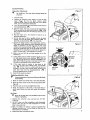
MAfN_-ENANCE
Carburetor
_"
Figu
Adjustment
BE CAREFUL!
procedure.
The chain will be moving
daring
7_
this
1,
Stop the engine.
2.
Remove the carburetor cover (Figure 7), Turn the high
speed
(Figure
8} and low
speed
mixture
screws
clockwise _
(Figure "8} until they stop. Don't tighten
them. you may damage the needle seats]
3.
Turn the high speed and low speed mixture
tUrn counterclockwise
_
.
4.
Start
the engine,
re
screws one fu II
if it stops, increase the idle speed (Figure
•. '!8} by turning the idle Speed screw clockwise
_
. Keep
dirt and _awdust away ¢rom the carburetor while the covet
;-;
is removed.
5.
Run the engine for a few
operating temperature.
6.
Set the idle speed as fast as possible without
the
moving. Turn the idle speed screw clockwise _
faster idle. counterclockwise
1€_ for slower idle.
7.
Squeeze the trigger quickly. If the engine stops, restart it.
The engine should accelerate without hesitating when the
trigger is squeezed. If _ does not, turn the low Speed
mixture screw counterclockwise
_
1/16 of a tUrn and
d3eck the aocaleration again. If the idle speed slows while
adjusting the Jow speed mixture, reset the idle speed as in
step 6. Continue step 7 until acceleration is smooth.
8,
9.
Make a test
carbu[etor!)
minutes
cut v_ith the saw {keep
to bring
it up to
chain
for
10.
If the engine seems to weaken or lose power in the
cut, turn the high speed mixtUre screw Counterclockwise
_
f/16 of a turn at a time until the saw cu_s
smoothly.
The high speed mi×ture screw should not be
open more than 1¼ turns (counterclockwise
_
}
from the stopped position in step 2.
1 I.
Reset the idle speed (see step 6).
_v
•
ca_aretor
High speed
Mix Screw
I_ow Speed
Mix Screw
c_,er
Incorrect placement of _
from working,
r"
co_er,will prevent the choke
.....
"
1.
Move
2.
Move the choke shutter
Figure 8).
the choke knob all the way i_ the e_hoke direction.
3,
Place the cover on the saw and tighten
4.
Check the operation of the choke. If the
won't move, remove the cover and repeat
above,
to the choke closed position (See
the screw&
knob sticks or
the procedure
Air Filter
Clean the air filter aflcer every 10 tanks of gas or every
• 5 hours of operation.
the
Choke Closed
sawdust out of the
If the engine seems to smoke excessively in the cut, turn
• the high speed mixture screw clockwise _
I/t6 of a
turn. Repeat step 8 and 9, if necessary. WARNING:
The
high speed needle must never be less than 7/8 turn open.
Too lean of a setting will quickly ruin tl_e engine.
Re+-_
Figure 8 _
1.
Remove
carburetor
Cover and
:
2.
(Fig ure g).
DO NOT clean your filter in gasoline or other flammable
solvent. 8tow the dirt off with compressed air or wash
filter in soap and water,
3.
Note: The filter is o;I soaked. It must be resoaked after
cleaning. Else 30W oil or _.'-'_in oil. Soak the filter with oii
then squeeze out completely.
4.
Replace the filter and carburetor
cover_
pal!
out
the
fi_ter
FIghre
9
Starter Rope
If your rope breaks near the pulley, it can be repaired
method. Otherwise, replace the _:ope.
.:Figure 10
1.
Remove the pulley screw and pulley very carefully. The
recoil spring lies beneath the pulley. Twist the pulley
gently as you pull up to release the spring, The spring
must stay in th_ housing, flat against the bottom.
2.
Burn the rope end and run it through a rag before it cools,
An enlarged end w_ll keep the rope from fitting onto the
pulley. Don't touch the burned end. It is hot!
3.
Fe_ the rope through the housing, -into the pulley, and up
through the pulley hole as in Figure 10, A sharp objector
_iff wire will help you get the rope through the hole.
4o Tie a knot
the pulley.
Replace the pulley in the housing, Be sure the pulley is all
the way down and the spring is engaged. Replace and
tighten the pulley screw,
6.
Rewincf
all
the
ootJntercfockwise
7.
Pull about _; inches out as shown
rope in the pulley slot.
8.
Make
thre_ complete
tucns
of the pulley
c|ockwise _
. Pull the starter handle to the full extent of
the rope and let the rope rewind slowly.
BAR
_F
• 1.
,
,,
in the end of the rope.'Pult it very tight agaln_t
5.
GUIDE
_
by th_s
rope
onto
the
pulley
by
turrEng
in Figure 11 and set the
MAINTENANCE
Check the condition of the guide bar often, A worn
bar will damage the chain and make cutting harder.
Figure 12 shows a cross-section of the guide bar. Keep the
edges square as in 1 with a flat file.
:2. Rollover is shown in 2 . This will causc you to press extTa
hard when cutting.
Figure 12
1.
' 2
Correct
Rails &
3.
Worn rails are shown in 3 . This occurs reost often at the
guide bar nose.
4.
Uneven
rails are shown in 4 . This wffl cause the saw to
cut on an angle.
Rollover
Worn
Rails
Uneven
Rails
,J,
5.
Keep the raiis ftat and srjuare asshown
in I
.
J ,,,
Figure 13
"-_-:CHAtNSHARPEt_'ING (Refer•to page 9 for tools}
Figure 14
O Keep Your Chain Sharp
File Guide
Dirt will dull a chain instantly.
dirt.
Keep the chain out of the
If _he chain cuts to one side, it is dul!,
_xtra
rough cutting
Powder-like
Align The File Holder
....
Figure 15
\
Cutting
Press Hard
,,
,,
,
,
iS a sign of a dull chain.
wood chips mead a dull chain.
is much easier a_'f_r
with _ sharp chain.
O To Sharpen
Figure 16
1. <Jet the €halo tension right. You must still be able to move
the cha_r_around _he bar.
i
2,
(;lamp the guide bar in a vise. Don't
Clamp in the center of the bar.
clamp the chain!
3.
Use 5/32"
4.
Sharpen all the cutters away from you first, Then turn the
saw around and sharpen the cutters on the other side.
/
t
File In One Direction Only
/Mways Check Depth G_uges
5.
Align
I3,
. •
fife only.
the file holder
markswith
using the 30 ° angle
the bar as shown in Figure
mark on file
holder.
6.
Hold t_e file level, perpendicular
7,
File in ONE direction
to the bar, Figure
8.
Press hard[ Two or three strokes should do it.
14.
9.
only! Figure 15,
Always check the depth gauge w_th the depth gauge filing
guide after filing, If the depth gauge sticks out, fileitoff
with a flat file, Figure 16.
STORING YOUR CHAIN SAW
2.
Once you have finished Using the saw and it is to be idle for
s_veral months, follow these steps before storing the saw.
3.
1.
4, ' Coat guide bar and chain with oi! to pr_ent rust.
5. Store in a dry area end cover to protect from duSt.
Drain fuel from the tapk.
ma i nfenance
kit
Star_Er_ir_'and
allow tQ run at idle speed until all fuel is
used.
Drain oH from oil tar}t<.
MA,.TE.ANC
,T =S.,T. ",'our
.BUT
.Or
sAW
•Available t]lrough your nearest Sears Service Center
KEY NO.
1
,2
3
4
5
6
PART NO.
55046
55004
31059
30005
55023
51045
51046
51047
CATALOG I_O.
32-36516
32-36524
32*36403
32-36557
32`3622
32-3623
3"2-3617
OESCRtPTION
_File Holder (includes file}
File (5]32" die.)
Spark Plug Wrench
Spark Plug';ha mpion CJ_
az
Depth Guage(.025
)
10" replacemen_ chain
t2" replacement chain
14"" replacement chain '
Acces_Joriesa_ra(lable _l_rougfi your nearest Sears Store or Ca1_|og outlet,
A(I items except numbers
CATALOG NO.
32-36513
32`36621
32-36554
.
32-36555
32`36363
32-36364
32-36365 _
3 & 5 shown above,
I_ESCRIP_-_O_
PlasticChain Guard
Carry C_se
Bar& Chain Lubricant
Two_:ycte Engine Oil
Replacement 10"°Bar
Replacement ]2"' Bar
Replacement 14" Bar
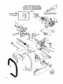
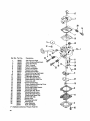
SEARS CHAIN SAW PARTS LIST
Craftsman 2.0--10" (Model 358.352030)
Craftsman 2,0--12'" (Model 358.352060)
Craftsman 2.0-14" {Model 358.352070)
Figure 1.
10
SEARS
Craftsman
Craftsman
Craftsman
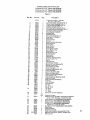
CHAIN SAW PARTS LIST
2,0-10"" (Model 358.352030)
2.0-12" (Mode( 358.352060}
2.0-t4"
{Model 358.352070)
Figure1.
Re(. No.
1
3
4
5
6
7
8
9
10
11
12
17
18
19
20
21
22
23
24
25
26
27
28
29
3O
31
32
33
34
35
36
37
38
39
4O
41
42
43
44
45
46
47
.48
49
50
51
:52
53
54
55
56
57
58
59
60
6!
62
63
.
.
Part No.
15229
11309
23783
42023
10373
15428
15036
626605
15127
15126
39t 11
24158
39082
3933
3934
15128
11311
15251
23927
23929
24052
24126
24124
15163
23807
23881
15168
15147
23806
1726
15245
23865
• 15254
23805
35002
19045
15242
23791
23878
23373
15247
23883
21025
15141
23877
21024
15252
23364
23363
19082
23366
23367
15241
23808
19093
23819
23804
23803
39087
390_ 1
53869
23931
Cry.
2
I
1
Description
Screw- 1@24x 1-3/8
Fan Housing
Rope & Hand.Starter
Spring-Starter
I
1
1
1
1
1
1"
1
1
1
1
2
1
1
1
1
I
t
1
1
1
!
2
1
1
1
2
1
1
1
I
1
3
1
1
1
1
I
1
1
1
I
1
1
1
1
I
1
''1
1
1
1
1
1
1
1
1
1
Pulley-Starter
(includes Re(. No, 7)
Washer
Screw- 10-24x½
Nut-5/16-24
Washer-Flywheel
Key-Flywheel
Flywheel Assembly
Lead-Switch
Lead-Spark Plug (includes 19 & 20]
Connector-Spark
Plug
Boot-Spark Ptug
Screw-8-32x% Sums
Bar Clamp
Nut-Bar Mounting
Decal-Bar Clamp (Model 2.8-- 10")
Decal-Bar Clamp (Model 2.0o12"'1
Decal-Bar Clamp (Model 2.0-14")
D_eal-lnstructio_
(left half)
Decal-Instruction
(right half)
Serew-10_24×7/8
Choke Knob
CovePCarburetor
Screw-10o24xS/8
Wave Washer
Lever-Choke
Screw-8-32xS!16
Tapping
Screw- 10-24× 1-5/8
Spacer-Choke Shutter
Wave Washer
Shutter-Chok e
Carburetor _WA-19)
G asket-Carburetor
Screw-_ -20X 11/ 16
Air Filter
Handle & Carburetor
Housing
Boot-Throttle
Wire
Screw*No. 8x_ Tapping
•Fuel Line (Bulk No. 8133)
Serew-_-20x¾
Fitting-Fuel Line
Line-Fuel Pick-up (Bulk No. 8!33)
Washer-Fuel Pick-up Weight
Filter-Fuel
Weight-Fuel Pick-up
Gasket-Carburetor
Housing
Reed Valve
Washer-Reed Valve
Screw-No. 6x5/16 Tapping
Cap-Fuel Tank
• --_'SeaI-Fpet Tank Neck
Fuel Tank
Trigger*Th rottle
Wire-Throttle
"Ignition Module, includes 17 & 18
, Lead-Switch
Owners Manuat
: "
Warranty decal
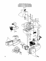
11
SEARS
Craftsman
Craftsman
Craftsman
=
CHAIN SAW PARTS LIST
2.0-- 10'" (Model 358.352030}
2.0--12 _°(Model 358.352060)
2.0--14" (Model 358.352070)
,, ,,,,,,,.
Optional
temperature
limiting
mUffler cover referred
to on page 15.
IUSI_. ON MATING
OF CRANKCASE
Hi=
10
11
2
57
40
41
38
12
SURFACES
HALVES)
SEARS CHAIN
Craftsman
Craftsman
Craftsman
2.0-10"
2.0-12"
2o0-14"
SAW PARTS
LIST
(Mode! 358.352030)
(Model 358.352060)
(Model 358.352070)
Figure 2.
Ref. No.
Part No.
Qty.
I
10194
1
2
3
4
5
6
7
8
9
10
11
12
13
14
t5
16
17
18
i9
20
2t
22
23
24
25
26
27
28
29
30
31
32
33
34
35
36
37
38
39
40
41
42
43
44
45
46
47
48
49
50
1
1
1
1
2
2
I
!
12
1
t
2
1
I
•1
2
I
1
2
2
1
1
1
1
1
1
1
1
7
1
1
1
1
1
1
1
1
2
1
1
!
1
1
2
1
I
t
2
1
1
1
1
1
1
52
53
15236
23492
15135
15249
19059
32026
22172
23887
32025
22158
22152
23843
23789
19088
11287
15239
300O5
23794
1666
23797
23796
23535
23795
15169
23788
23786
23787
15235
15238
23874
t949
23519
48032
32028
15173
10158
22138
15037
1648
15151
23824
19089
21026
19091
10195
23801
23802
1643
44135
44132
44133
51045
51046
51047
31063
30054
54
52043
55
56
57
58
15004
23653
23656
10221
!
1
I
59
60
61
62
63
64
65
22222
24091
24049
15342
10252
32--36151
1697
7
I
1
3
1
1
!
51
_
t
AS
Req.
1
Description
Crankcase Assembly -- includes
Nos. 2, 3o 4, 5, 6, & 7.,
Screw-Bar Adjust. (included in No. 1)
Pin-Bar Adjust. (included in No. 1)
Lock Nut-8-32 (included in No. f)
Stud-Bar (included in No. 1)
Seal-Crankshaft
(included in No. 1}
Bearing_CranksMft
(inpluded in NO. 1}
.Crankshaft Solid State Ignition
Thrust Washer-Crankshaft
Bearing-Roller
Conhecting Rod
Piston Kit; includes No. 13
Ring-Piston Pin Retainer
Piston Ring
Gasket-Cylinder
Cylinder
Screw-]&-20x_ Socket Head
Spark Plug-C J-8
8ody-Mu filer
Screw- t0-24x½
Baffle-Muffler
Screen-Spark Arrestor
Spacer-_fuffler
Cover
Cover-Muffler
Screw-10-24x1-7/16
Knob-Kill
Switch
Ramp-Switch
Cfamp_Switch
Screw-No. 8x9116 Tapping
Screw-1O-24x 11116
CapOil
O-Ring-Oil'Cap
Spacer-Clutch
(inside}
Sprocket & Drum {includes 35)
Bushing-Clutch
Drum
Thrust Washer (outside)
Clutch Assembly
Handlebar (358.352020--10")
Screw- t 0-24x5/8
Screw-_-20xl¼
Hex Bolt
Washer-Handlebar
(top}
Check
Va!ve-(_,_ I Ta,-{k P{er-_'_->e
Gasket-Check Valve
Line-Oil Discharge (Bulk No.'8133)
Gasket-O il Pump
"
Body Assembly-Oil
Metering
Filter-Oil
Cover-Oil Pump
Screw-8-32x ½
Bar-10"
Bar-12"S.
N.
Bar-14" S. N.
10"" Chain
r
12"° Chain
14"' Chain
Wrench-Bar & Chain Adjusting
Sealant-Crankcase
Chain Repair Kit (includes t Drive llnk, 2 Preset tie
straps, 2 Plain tie straps, I Guard drive link}
Serew-8-32x5/16
(358_352060 & 358.352070}
Chain-Oil Cap (358.352060
& 35&352070)
Retainer-Chain (358.352060
& 358.352070)
Oil Cap Ass'y {358.352060
& 358.352070)
(includes 31, 32, 55, 56 and 57}
Handlebar wicover (358.352060
& 358.352970)
Hand Guard
Cap-Hand Guard
Screws-Hand Guard
Hand Guard Assem _y (! ncludes 60, 6 I, 62)
Optionel temperature
limlting
muffler cover
Spring-Clutch
13
Ref. No. Part No.
1
35007
2
35003
3
35033
4
35034
" 5
35006
6
35008
7
35009
8
35012
9
35011
t0
35013
II
35014
12
35015
13 .... 35016
14
35035
15
35018
16
35021
t7
35017
18
35036
.19
35023
20
35038
21
.35047
22
35024
23
35O53
24
35039
25
35027
26
35028
27
35042
28
35031
35049
Description
Clip-Throttle Shaft
Cover-Metering Diaphragm
Cover-Fuel Pump
Shaft-Throttle
Shutter-Throttle
*Valve-I nlet Needle
*Gasket-Fuel Pump
*Gasket-Circuit Plate
*Gasket-Metering Diaphragm
*Diaphragm-Fuel Pump
*Diaphragm-Metering
.
*Screw-Throttle Shutter "
Screw-Metering Lever Pin
Screw-I die Adj,
*Screw-Circuit Plate
Screw Assembly.Metering Cover
Screw-Pump Cover
Sprlng-Htgh Speed Needle
Spring-Idle Needle
Spring-Idle Adj. Screw
*Spring-Metering Lever
Spring-Throttle Return
Needle-High Speed Adj.
Needle-Idle Adj.
*Screen-inlet
*Pin-Metering Lever
Plate-Circuit
* Lever-Metering.
Kwik Kit-Repair
(*I Indicates contents of Repair PartsKit,
'14
24
4
18
6
OPTIONAL
TEMPERATURE
LIMITING
MUFFLER
COVER
In some states, such as California,
laws covering chain saws (having internal combustion engines),
when used in areas covered by forests, brush or grass (excluding
residential lawns and landscaped
areas}, necessitate fitting the saw's muffler
with an additional heat shield to reduce muffler surface
temperatures.
Sears offers such a shietd as an optional aCcessory kit. Order Muffler Heat Shield
Accessory Kit as listed below. Check" with your state conservation or forestry department
about
their regulations
before operating this Sears chain saw on any forest-covered,
brush-covered,
or
grass-covered areas Oregon & Washington have similar
requirements
with respect to forestcovered lands.
5,EA6, ,CHAINSAW
358.352030,
352060, 352070
MUFFLER
HEAT SH[E,L D KIT
PART NO,-32 36151
The mufflers on the above chain sawsare equipped with a "spark arrestor" to help prevent exhaust
sparks from igniting flammable materials. Some states, such as California, require individuals using
this chain saw in areas covered by forests, brush, or grass (excludingresidentiat lawns and landscaped
areas) to maintain the "spark arrestor" in effective Working order. Instructions covering proper
maintenance and replacement are contained in your Owner's Manual..
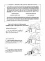
INSTRUCTIONS
FOR INSTALLING
TEMPERATURE
LIMITING
MUFFLER COVER
R.EMOVE STANDARD
COVER
1.
Use a 5/16"
socket wrench to remove the
screw located in the center of the muffler cover.
Remove the muller
cover from the muffler
body
.(figure 1.) Do not remove inside parts.
INSTALL VENT COVER
2_ Insert the temperature limiting muffler cover
(figure 2.) into the muffler body until it seats on
the inside parts, Replace and tighten screw. Do not
use an air wrench to tighten screw.
Figure 2
.,.
NOTE:
It is not necessary to remove ins{de muffler
parts to install temperature
limiting
muffler cover.
If inside parts are removed, the diagram shows how
parts are reassembled.
,
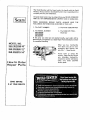
•
The Model Number will be found under the handle with the Serial
Number. Always mention the Model Number when requesting service
or repair parts for your Chain Saw.
lSears
All parts listed herein may be ordered from any SEARS, ROEBUCK
AND CO. OR SIMPSONS-SEARS LIMITED retail or catalog store.
WHEN ORDERING
REPAIR
PARTS, ALWAYS
GIVE
FOLLOWING INFORMATION
AS SHOWN IN THIS LIST.
THE
1. The PART NUMBER
3. The PART DESCRIPTION
2. The MODEL NUMBER
358.352030
358,352060
358.352070
4. The NAME OF ITEMChain Saw
If the parts you need are not stocked locally, Four order will be
electronically transmitted to a Sears Repair Parts Distribution center.
for expedited handling.
" "
MODEL
NO.
358,352030_0""
358.352060-12""
358.352070-14'"
How to Order
Repair
Parts
SEARS SERVICE
IS AT YOUR
SERVICE
When you buy merchandise
from Sears you get an extra
something that nobody else
can offer...
Sears Service.
Across
town
or
across
the
country,
Sears Service follows
you,
providing
trustworthy,
competent
service technicians
using
only
Sears
specified
factory parts.