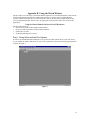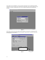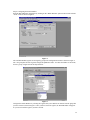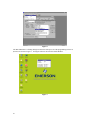
1
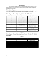
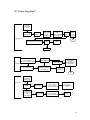
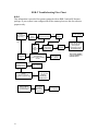
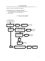
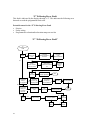
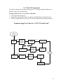
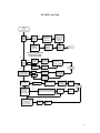
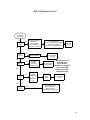
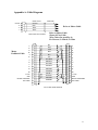
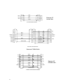
Troubleshooting Guide
En/Epsilon Drive Systems and FM Module Products
November 15, 2001
P/N 400333-01
Revision: A1
ã2001 Control Techniques - All Rights Reserved
Table of Contents
INTRODUCTION ------------------------------------------------------------------------------------------------------ 2
DRIVE STATUS DISPLAY ------------------------------------------------------------------------------------------ 2
HOW TO USE THIS MANUAL ------------------------------------------------------------------------------------- 3
SAFETY INSTRUCTIONS ------------------------------------------------------------------------------------------- 3
“C” RMS FOLDBACK DISPLAY ---------------------------------------------------------------------------------- 5
“c” STALL FOLDBACK DISPLAY -------------------------------------------------------------------------------- 7
“ “*” FLASH INVALID”---------------------------------------------------------------------------------------------- 8
“ A” DRIVE OVERTEMP” ------------------------------------------------------------------------------------------ 9
“I” “POWER-UP SELF-TEST” ----------------------------------------------------------------------------------- 10
“N” “NVM INVALID” ---------------------------------------------------------------------------------------------- 11
“U” “INVALID CONFIGURATION”---------------------------------------------------------------------------- 12
“H” “HIGH DC BUS FAULT”------------------------------------------------------------------------------------- 13
“Z” “POWER STAGE FAULT” ---------------------------------------------------------------------------------- 15
“U” “LOW DC BUS FAULT”-------------------------------------------------------------------------------------- 17
RSR-2 TROUBLESHOOTING FLOW CHART--------------------------------------------------------------- 18
“e” “ENCODER STATE FAULT” -------------------------------------------------------------------------------- 19
“E” “ENCODER LINE FAULT”---------------------------------------------------------------------------------- 20
“M” “MOTOR OVER TEMPERATURE FAULT” ----------------------------------------------------------- 21
“S” “RMS SHUNT POWER FAULT” --------------------------------------------------------------------------- 22
“O” “OVER SPEED FAULT” ------------------------------------------------------------------------------------- 23
“F” “FOLLOWING ERROR FAULT” -------------------------------------------------------------------------- 24
“L” CW/CCW LIMIT FAULT ------------------------------------------------------------------------------------ 25
TROUBLESHOOTING FLOW CHART FOR “CW/CCW LIMIT FAULT” --------------------------- 25
ALL LED SEGMENTS ON----------------------------------------------------------------------------------------- 26
ALL LED’S ON FAULT -------------------------------------------------------------------------------------------- 27
FM-3 HARDWARE ERROR--------------------------------------------------------------------------------------- 28
i
“FM-3/4 HARDWARE ERROR” --------------------------------------------------------------------------------- 29
APPENDIX A: CABLE DIAGRAMS ---------------------------------------------------------------------------- 31
APPENDIX B: USING THE WATCH WINDOW ------------------------------------------------------------- 33
APPENDIX C: UPDATING FIRMWARE USING THE FLASH UPGRADE PROCESS ------------ 37
APPENDIX E: EN AND EPSILON DRIVES PHYSICAL CONNECTIONS ---------------------------- 44
APPENDIX F: SERIAL LOOPBACK TEST ------------------------------------------------------------------- 46
ii
Troubleshooting
Section
1
Introduction
This document is intended to help a user troubleshoot the Control Techniques E Series
and Epsilon Series Servo Drives. The user will be pointed to possible solutions through Fault
descriptions and Flowcharts.
Drive Status Display
The 14-segment LED display is capable of displaying most letters of the English alphabet
in both lower and upper case. Some characters outside of the alphabet are also used.
Drive Display - Normal Operating Modes – No FM Module
Displayed Character
b
d
P
V
T
+
C
Status
Brake Engaged
Drive is disabled
Drive is in Pulse Mode
Drive is in Velocity Mode
Drive is in Torque Mode
Summation Mode
RMS Foldback active
c
Stall Foldback active
For Motor speed
. (period)
Ready to Run
*(asterisk)
Reboot
Description
Brake Control Output = On
Power Stage is disabled
Ready to receive Pulses
Analog Velocity mode
Analog Torque mode
Velocity Summation Mode
Motor Torque limited to
80%continuous
High Current demand for
extended period of time
prevents drive damage
If period missing Drive in
STOP mode
Displayed during a Drive
reboot after download
Table 1
Drive Display - Normal Operating Status Codes – EN with FM Module
or Ei Drive
Table 2
2
Displayed Character
R
Status
Ready
d
h
X
J
P
\
Disabled
Homing
Indexing
Jogging
Program
Stopping
Description
FM-3/4 ready to execute
motion command.
Power stage disabled
Drive is homing.
Index is executing.
Jog is executing.
Program is executing.
Drive is decelerating.
How to use this Manual
Fault Codes
The drive has several built in Fault detection circuits. If a fault is detected, the drive will
display a specific Fault code character.
Fault Description
A brief description of the specific fault and possible causes are found just prior to the
Troubleshooting Flow Chart.
Troubleshooting Flow Charts
Troubleshooting Flow charts are used to guide technicians through the fault isolation
process. References to connector and cable pin outs are included within the Flowcharts.
An Appendix contains the relevant cable pin outs.
Resetting Faults
Some of the detected faults may be reset using the front panel mounted pushbutton. Other
faults require the power to be cycled. The cause of the fault should be understood and
corrected before resetting.
Important Contact Information
Telephone: (952) 995-8000 or (800) 397-3786
FAX: (952)-995-8099
Website and Email: www.emersonct.com
Technical Support: (952) 995-8033 or (800) 397-3786
Technical Support Email: [email protected]
Training Email: [email protected]
Safety Instructions
Failure to follow safe installation guidelines can cause death or serious injury. The
voltages used in the product can cause severe electrical shock and/or burns, and could be
lethal. Extreme care is necessary at all times when working with or adjacent to it. The
installation must comply with all relevant safety legislation in the country of use.
Qualified Person
For the purposes if this manual and products, a “qualified person” is one who is familiar
with the installation, construction and operation of the equipment and the hazards
involved. In addition this individual has the following qualifications:
• Is trained and authorized to energize, de-energize, clear, ground, and tag circuits and
equipment in accordance with established safety practices.
• Is trained in the proper care and use of protective equipment in accordance with
established safety practices.
• Is trained in rendering first aid.
3
“C” RMS Foldback
A “C” indicates RMS Foldback in the display window on the EN/EB/EI drives. It is an
indication that the RMS current Foldback is active. This is not a fault, does not disable
the drive. Output RMS current limit is returned to 80%.
Potential Causes for RMS Foldback
• Excessive Load or Friction
• Motor does not match DDF file or Drive type
• Corrupt Motor DDF file
• RST Motor phases incorrectly wired
Notes
4
“C” RMS Foldback Display
"C"
RMS
Foldback
Excessive
Load
Yes
Return
to
Normal
Load
Investigate
- Check Foldback RMS in Watch Window*
- Wrong drive/motor for application size
* See Appendix B for
information on
Watch Window
No
Incorrect
Motor Selected
for
Configuration
Yes
Select Correct
Motor from
Setup View
or Motor Tab
Download
Known Good
Application
Yes
Return to
Normal Operation
No
No
Corrupt
Motor DDF
file
Yes
Reinstall
PowerTools
FM or Pro
RST Motor
Phases Incorrectly
Wired
Download
Known Good
Application
Yes
Return to
Normal Operation
Yes
See
Appendix A
For
Correct Wiring
for Eb/Ei/En
Wire
Correctly
per diagram
End
5
“c” Stall Foldback
A “c” indicates Stall Foldback in the display window on the EN/EB/EI drives. This is not
a fault and the drive will continue to operate. This display indicates that the current
command to the motor is 80% of the rated stall current. Motor torque and drive current
are reduced until the motor commanded velocity exceeds 100 RPM or the torque demand
is reduced.
This is done to protect the IGBT’s from excessive power loss due to a combination of
slow motor speed and high torque. IGBT’s can overheat under these conditions unless
current is reduced.
Potential Causes for Stall Foldback
• Sustained high current demand at low speed
• Wrong motor selected for configuration
• High inertia mismatch
• RST Motor phases incorrectly wired
• Tuning parameters not optimized
• Torque is commanded when machine path is blocked or stopped.
Notes
6
“c” Stall Foldback display
"c" Fault
Stall Foldback
Search for
causes of
Increased
Load
Yes
Excessive Load
Return Load to
Original
Size/Value
Return to
Normal
Operation
No
Yes
Incorrect
Motor Selected
for
Configuration
Select Correct
Motor from
Setup View
or Motor Tab
Download
Known Good
Application
Return to
Normal Operation
No
Yes
High Inertia
mismatch
Determine
potential
causes
for mismatch
No
RST Motor
Phases Incorrectly
Wired
No
Tuning
Parameters
not Optimal
Yes
Yes
See
Appendix A
For
Correct Wiring
for Eb/Ei/En
Refer to
Tuning
Procedure in
Epsilon E Series
Reference Manual
Use Emersize
program to
determine
correct
motor/drive
match
Wire
Correctly
per diagram
Download
Known Good
Application
Contact
Technical Support
for Assistance
Download
Known Good
Application
Reutrn to
Normal Operation
Reutrn to
Normal Operation
End
7
“*” Invalid Flash
This fault is indicated by the display showing an Asterisk. It generally indicates that the
“.fsh” (Flash) file is invalid. The most common cause of this fault is an interruption of the
update of a Firmware Flash process.
Potential causes for the Flash Invalid fault
• Incompatible file for the hardware present
• Corrupt flash file
“ “*” Flash Invalid”
"*" Fault
Asterisk Displayed
Invalid Flash
Incompatible file
for Hardware
Present
Remove Power
& FM Module
Base Drive
OK
No
Corrupt
Flash File
Flash
Upgrade
Base Drive
See Appendix C
End
Very Important Notice!
Before attempting
Flash upgrade
contact Tech
Support.
Notes
8
Yes
Flash
Upgrade
FM Module
See Appendix C
“A” Drive Overtemp
This fault is applicable to the Epsilon Drive only. It is indicated by the display showing
an “A”. If the equipment cabinet that the drive is mounted in has any problem with its
circulation of air or the cooling equipment malfunctions this fault will likely occur.
Potential causes for the “A” Drive Overtemp fault
• Sensed temperature in the IGBT (Insulated Gate Bi-polar Transistors a.k.a. Power
Stage) has exceeded 100° Centigrade (212° F).
• Noise
“ A” Drive Overtemp”
"A" Fault
Drive Overtemp
Epsilon Only
Cycle Power
to Reset
Yes
Drive Resets
Possible
Noise Problem
No
Check for
continuity between
Drive Ground and
Motor Ground
with Power Off
Yes
Ready for Normal
Operation
No
Check Cable Routing and
Spacing between
Feedback and Motor Power
Cable or any other cable with
potential to generate noise
Remove Power
Allow Cool Down
Approx. 30 minutes
Yes
Check for
Air Flow Restriction
Air Filters change
if needed
Air Conditioning problems
Drive Resets
No
Check Application
High Ambient
Temperature
in Cabinet
o
Above 40 C
Derate by
3% for every degree
o
o
40 to 50 C max
Contact
Tech Service
End
Notes
9
“I” Power-Up Self-Test
This fault is indicated by the display showing a “I”. This display indicates drive did not
complete its internal self test.
Potential causes for the “I” Power-Up Self-Test fault
• Incorrect firmware in drive or module
• Failed internal component
• Failed FM module
“I” “Power-Up self-Test”
"I" Fault
Power-Up Self-Test
Drive and FM Module
Connect Computer
to Drive,
Establish
Communications
Check Module
Flash level
Upgrade
successful
Flash Module
See Appendix C
No
Check Website
for latest Flash Rev.
and download
Return Module
to Factory
Yes
End
Return to
Service
Drive Only
Recycle
Power
Functions
Normally
No
Return Drive
to Factory
End
Very Important Notice!
Before attempting
Flash upgrade
contact Tech
Support.
Notes
10
“N” NVM Invalid
This fault is indicated by the display showing a “N”. NVM stands for Non Volatile
Memory.
Potential causes for the “N” NVM Invalid fault
• Corrupt configuration file
• Corrupt flash file
• DSP is non operational
“N” “NVM Invalid”
"N" Fault
NVM Invalid
Yes
Use Reset P/B
to Reset
Return to Operation
No
Download
known good
Configuration file
Yes
Return to Operation
No
Update Module or
Base Drive
to latest
Flash (.fsh) file
Yes
Return to Operation
No
DSP
Non Operational
Return to Factory
End
Notes
11
“U” Invalid Configuration
This fault is indicated by the display showing a “U”. This display indicates a change in
the physical configuration of the drive. It is not known if setup data in the FM module
matches the current drive and motor attached.
Potential causes for the “U” Invalid configuration fault
• FM module not on the drive at previous power up
• FM module on the drive at this power up was missing at the prior power up
“U” “Invalid Configuration”
"U" Fault
Invalid Configuration
FM Module
Present
prior to last
Power Cycle
No
Press and Hold
Drive Reset P/B
for 12 seconds
Display
Changes
to "d"
Ready for
Normal
Operation
Yes
End
No Module
Present
prior to last
Power Cycle
Notes
12
Download
Configuration file
“H” High DC Bus
This fault is indicated by the display showing a “H”. The DC bus is internal to the drive.
This indicates a fault involving the DC bus and voltages or with its associated
components.
Potential causes for the “H” High DC Bus fault
• DC Bus exceeds 440 VDC (EN), 415 VDC (Epsilon)
• Open Shunt Resistor either internal or external
• RSR-2 module malfunction or improper installation
• High AC input line
• High inertial load, deceleration ramps too aggressive
“H” “High DC Bus Fault”
"H" Fault
High DC Bus
EN-204
All Epsilon
Drives
System Uses RSR-2 Module
and ES Unit
External Shunt Resistor
Yes
Use RSR-2
Troubleshooting
Procedure
No
EN-208
And EN-214
Drives
Open Internal
*
Shunt Resistor/Shunt Fuse
Potential Misapplication
No
or External Resistor
RSR and ES Maybe Needed
Contact Tech Support
Yes
Return
to Factory
"H" Fault
High DC Bus
Returns
to
Normal Operation
No
Return
to Factory
End
Yes
High AC
Input line
Yes
Monitor
AC Input
>264 VAC 47-63 Hz
"H" Fault
High DC Bus
High Inertia Load/
Decel Ramps
Overly Agressive
Yes
> 264 VAC
Investigate
High Inertia
*Shunt Fuse or Resistor cannot
be checked in field.
No
Reset
with Reset P/B
Investigate Cause
for Increase
Examine Program
Modify Motion
AT/DT/VEL
as required
Returns
to
Normal Operation
No
Return
to Factory
End
13
“Z” Power Stage Fault
This fault is indicated by the display showing a “Z”. This indicates a fault in the Power
Stage logic power supply or the Power stages of the drive.
Potential causes for the “Z” Power Stage fault
• Power Stage over-temperature or over-current
• Power Stage switching transistor failure
• Loss of Power Stage logic power supply
• Use of improper serial or sync cables
• Motor shorted to ground
• Motor Phases shorted
Notes
14
“Z” “Power Stage Fault”
"Z" Fault
Power Stage
Fault
No
Shorted
Motor Stator
Disconnect
Motor Power
Cable
at Motor
Remove
Power
Ohm out
Motor
Use Procedure
in Appendix D
Stator
OK
Return
Motor
To
Factory
Segment #1
Ohm Out Motor Cable
See Appendix A for Daigram
Cable
OK
No
End
Replace
Cable
Yes
Segment 2
Internal Power Stage
Over Current;
Switching Transistor Failure
Segment 2
Reset with
Reset P/B (EN)
No
Reset Successful
Or
Internal Power Stage
Over Temperature
Check application
insure Drive Ambient
< 40 degrees C
Return Drive
To Factory
include Description
of Application
Reset by
Cycle Power
(Eb/Ei)
End
Fault Detected
when using
Serial Cable
Segment 3
Yes
EMC Serial
Cable
No
Ohm Out
Serial Cable
Continuity
pin 6 to pin 6
or pin 5 to pin 6
or pin 6 to shield/Gnd?
Not Recommended
for use with
E Series/Epsilon
Drives
Yes
Using
Sync functions
and
Sync Cabless
Yes
Ohm Out
Sync Cable
Continuity
pin4 to pin 8
or pin 4 to shield/Gnd?
Replace
Cable
15
“u” Low DC Bus
This fault is indicated by the display showing a “u”. Indicates a fault involving the DC
bus and voltages or with its associated components.
Potential causes for the “u” Low DC Bus fault
• DC Bus falls below 96 VDC
• Low AC line, below 90 VAC for greater than 50 milliseconds (3 cycles of 60 Hz)
• RSR-2 module malfunction or improper installation
• Repeated rapid cycling of AC power to amplifier
• Removal of AC Input AC Voltage Normal
• Removal of Aux Supply Powering Logic (Normal)
Notes
16
“u” “Low DC Bus Fault”
Yes
"u" Fault
Low DC Bus
Reset with
Reset P/B
Segment 1
Operation
Returns To
Normal
End
No
Measure
AC Input
On Power Connector
RSR-2 Malfunction
or
Improper Installation
Yes
When Input AC returns
to 96 to 264 VAC
Reapply Power
Refer to RSR-2
Troubleshooting
Flowchart
End
Segment 2
No
Rapid
Cycling of Power
Epsilon
"u" Fault
when using
Aux Power
Supply (+24VDC)
Yes
Remove Power
for 10 seconds
Use
PowerTools
to Disable
Monitoring
Reapply Power
Operation
Returns To
Normal
Open PowerTools
On Menu Bar
Click on Options >
Preferences>General
Segment 3
Check Box
Select Advanced Tab
Go On Line
with the Drive,
In Detailed Mode
Select Advanced Tab
Uncheck Box by
Low DC Bus Enable
Reset with
Reset P/B
Operation
Returns To
Normal
End
Increase Input AC
> 120 VAC or
Increase AT
(E-Series)
Segment 4
u Fault
Operation
Returns To
Normal
End
Low Input AC
< 120 VAC &
Rapid DT with
Large Load
24 VDC
APS
Disabled,
Low Bus
(Epsilon)
17
RSR-2 Troubleshooting Flow Chart
RSR-2
This information is provided for systems equipped with an RSR-2 and an ES Resistor
package. If your system is not configured in such a manner please use this for reference
purposes only.
RSR-2
May potentially
Be Faulty
"H"
Fault
on Drive
No
Check For
Correct Connection
Correct
Wiring
Normal Operation
Yes
Yes
Check
RSR-2
Fuse
Replace if
Open
RSR-2
Fault LED
On
RSR-2
Configured for
Master/Follower
Yes
Reset
Drive Ready
for Operation
Check Correct Connection
of ES Resistor
R+ and R-, Bus+ ands Bus-,
and PE
Cycle Power to
EN or Epsilon
No
Disregard
this Flowchart
Yes
Check for
+ 10 to +30 VDC
Between
*DC IN +24 V
and DC IN 0 V
Master
Check Connection
Trig Out to Follower Trig In
External Shunt
Operated with Over
Temp Sensing
18
Yes
Over Temp
Condition
Detected in
ES Unit
Functions
Correctly
Contact
Tech Support
Power LED On Steady,
Shunt LEDs On
During Drive
Deceleration Period
Trig In/Trig Out*
*Only active if RSR-2
is set up as Master or
Follower device.
“e” Encoder State
This fault is indicated by the display showing what appears to be a lower case “e”. It
indicates a fault involving the Encoder feedback.
Potential causes for the “e” Encoder State fault
• Any Encoder Output and its Compliment in same state
• Poor Shielding (Use “E” Fault Flow Chart)
• Custom Cable
“e” “Encoder State Fault”
"e"
Encoder State Fault
Check PowerTools Pro
Advanced Tab
Enabled
No
Recycle
Power
Returns to
Normal Operation
End
Yes
Invalid
Encoder State
Reporting
Check +5 VDC
J7 pin 7 to pin 17 (Gnd) EN
J6 pin 7 to pin 17 (Gnd) Epsilon
Should be 4.9 to 5.15 vdc
No
Return Drive
to Factory
End
Yes
Check Continuity
Encoder Phases
Motor to Drive Cable
Power Off
No
Replace
Cable
End
Cable
OK?
Yes
Contact
Tech Support
Noise
End
Use Emerson CT Feedback Cable
or
Cable with A, B, and Z shielded
Check Cable
Routing
Contact
Tech Support
19
“E” Encoder Line Fault
This fault is indicated by the display showing a “E”. Indicates a fault involving the
Encoder feedback.
Potential causes for the “E” Encoder Line Fault
• Loss of Encoder feedback
• Excessive noise induced into Encoder cable
• Drive and motor operating at different ground potentials
• Improper feedback wiring or potential cable issues
• Flexing of a non-flex cable
• Use of non-Emerson CT serial cables
“E” “Encoder Line Fault”
* EN & Epsilon
"E"
Encoder Line
Fault
shipped after
October 2001
Yes
Remove
FM Module
(if so equipped)
Reapply Power
Loss of
Encoder Feedback
Check +5 VDC
J7 pin 7 to pin 17 (Gnd) EN
J6 pin 7 to pin 17 (Gnd) Epsilon
Should be 4.9 to 5.15vdc
No
En Fuse
Open
Yes
No
*Resettable
Use PowerTools
Select Analog Mode,
Configure Drive and Motor,
Download to Drive
Fuse Open
Allow to cool
Reset is
Automatic
Select "Status" Tab or
"Watch Window" to
View "Position Feedback Encoder"
DO NOT Enable Drive
Rotate Motor Shaft by Hand
No
Yes
Counts are Displayed?
Increases with CW Rotation
Decreases with CCW Rotation
Yes
Return to
Normal Operation
Replace Motor
and Return
to Factory
No
Yes
Noise
Induced in Feedback
Cable
Check Routing
& Condition of
Feedback Cable
in Runs
Relay Coils W/O
Diodes in System
Recycle Power
Run Programs
Return to
Normal Operation
Replace Drive
and Return
to Factory
End
No
Motor and Drive
Operating at different
Gorund Potentials
Yes
No
Use of non-Emerson CT
Serial Cable
Check Continuity Motor Case
to Motor Feedback Connector Shells
J5* Epsilon or J8* EN
Must be Zero!
If Resistance Measured
Contact Factory
Tech Support
Replace Drive
and Return
to Factory
* Refer to Appendix E
for Connector Locations
Yes
Check +5 VDC
J7 pin 7 to pin 17 (Gnd) EN
J6 pin 7 to pin 17 (Gnd) Epsilon
Should be 4.9 to 5.15vdc
Replace with CT Approved Cable
End
No
Yes
Return to
Normal Operation
20
Motor Over Temperature Fault
This fault is indicated by the display showing a “M”. This indicates a fault involving
excessive motor temperature.
Potential causes for the “M” High DC Bus fault
• Motor thermal sense switch is open due to excessive heat build up in the motor.
• Flexing of a non-flex cable
• Improper wiring
• Defective thermal switch internally in the motor
• Noise
“M” “Motor Over Temperature Fault”
"M" Fault
Motor Over Temperature
Motor Thermal
Switch open
due to excessive
internal heat
Yes
No
Allow Motor to cool
Approximately 30 mimutes
Thermal Switch
Resets
Return to Factory
End
No
Yes
Disconnect
Motor
Feedback Cable
Flexing
of non Flex Cable
Check continuinty of
Motor Feedback cable pin A
Flex cable during test
Yes
Return to Service
Replace Cable
No
No
Yes
Improper Wiring
from Drive to Motor
No
Disconnect Motor Feedback Cable
at every connection point,
Yes
use ohmmeter to check
continuinty of Pin A in cable
If Flex cable try and Flex
No
Reconnect and Return to Service
Replace defective section
or entire Cable
Yes
Defective
Motor Thermal
Switch
Yes
Check Continuity pins T to A
of Motor Feedback Connector
MG/NT Motors
shall read short if switch is reset
Return to Service
No
Return to Factory
No
Noise
Check Routing
of Cables
Return to Service
End
Yes
21
“S” RMS Shunt Power Fault
This fault is indicated by the display showing a “S”. This indicates a fault involving the
drives internal shunt circuitry. The shunt power parameter is an internally calculated
parameter.
Potential causes for the “S” High DC Bus fault
• Internal shunt power calculation has exceeded capability of internal shunt circuitry
• High Inertial load
• High AC line
• Short rapid moves coupled with very short deceleration ramps
“S” “RMS Shunt Power Fault”
"S"
RMS Shunt Power
Fault
Internal Shunt Power
Calculation exceeds
capacity of
intenal shunt circuitry
Yes
Return
to
Normal Operation
Reset with
Reset P/B
No
Reduce
Load
Yes
High Interial
Load
No
Returns
to
Normal Operation
Check for
Increase in
Acutal Load
No
High AC
Input line
Yes
Yes
Monitor
AC Input
>264 VAC 47-63 Hz
No
Reset
with Reset P/B
Yes
No
Short Rapid
Moves coupled
with Very Rapid
Deceleration Ramps
22
> 264 VAC
Yes
Investigate Cause
for Increase
Determine
which Motions
cause fault and
alter as needed
Return
to Factory
End
“o” Over Speed Fault
This fault is indicated by the display showing a lower case “o”. This indicates a motor
over speed has occurred.
Potential causes for the “o” Over Speed fault
• Motor speed exceeds 150% of maximum value as defined in “stdmotor.ddf” file
• Actual motor speed exceeds programmed motor limit speed
• Pulse mode maximum frequency rating exceeded
• Noise
“o” “Over Speed Fault”
"o"
Over Speed
Fault
Speed Exceeds
150% of value
"stdmotor.ddf" file
Yes
Check "stdmotor.ddf" file
for exact Motor RPM Spec.
Investigate cause
of Motor Overspeed
No
Actual Motor Speed
Exceeds Programmed
Over Speed Limit
Yes
Check "over speed limit"
in software
Download
Corrected file
No
Pulse Mode
Maximum Frequency
rating exceeded
Yes
Reduce Incoming
Pulse Frequency
to < 8 Mhz
Return to Service
End
No
Yes
Noise
Check Contnuity
of Feedback Cable
Shield from
Motor to Drive
Check Routing
of Power and
Feedback Cables
Reset
using Reset P/B
23
“F” Following Error Fault
This fault is indicated by the display showing a “F”. This indicates the following error
detected exceeds the programmed limit value.
Potential causes for the “F” Following Error Fault
• Friction
• Faulty wiring
• Programmed acceleration/deceleration ramps are too fast
“F” “Following Error Fault”
"F"
Following Error
Fault
Yes
Disconnect
Motor from
Load
Friction
Check Movement
of All Parts
Moved/Controlled by
This Motor
Check
Lubrication
of All
Mechanical Parts
No
Gear Reducer
Used?
Check condition
and level of Oil
Reset
with
Reset P/B
Programmed
Accel/Decel
Ramps
Too Agressive
Yes
Examine
All Motions
that may be
Causing Fault
Add/Change
Reducer Oil
with Recommended
Oil
Return to
Normal Operation
Reconnect
Motor to
Load
End
Alter
Accel/Decel
Ramps for
Suspect Motions
Reset
with P/B
Return to
Normal Operation
No
Following
Error Limit
Setting too
Agressive
FM-2/3/4
Yes
Alter
Following Error
Limit
Reset
with
Reset P/B
Return to
Normal Operation
End
No
Faulty
Wiring
24
Yes
No
Inspect Motor
to Drive Wiring
Check Motor to Drive
Wiring for Splices
Reset
with
Reset P/B
Poor
Splices
Replace
Cable
“L” CW/CCW Limit Fault
This fault is indicated by the display showing an “L”. Encountering either Hardware or
Software limits may cause this fault.
Potential causes for the “L” CW/CCW Limit fault
• CW/CCW limit sensor active
• Reached the end of the hardware or software established limits in either direction
• Polarity of input function is incorrect for wiring configuration at the input connector
Troubleshooting Flow Chart for “CW/CCW Limit Fault”
"L"
CW/CCW
Limit Fault
Travel Limit
Prox Switch
Active
Yes
Jog
Off Switch
in Opposite
direction
No
"L" Fault
Resets
Automatically
Yes
Return to
Normal Operation
No
Check
Polarity of Input
Check
Input Wiring
for Polarity
Selected
Change Input
Polarity/
Modify Wiring
End
Yes
Travel Limit
Software Limit
Active?
Check/Adjust
Software
Limit
Jog
Off Limit
in Opposite
direction
"L" Fault
Resets
Automatically
Return to
Normal Operation
25
All LED Segments On
All LED segments being on simultaneously indicate this Fault.
Potential causes for the All LED’s On fault
• Wrong Serial cable
• Low AC
• Low APS Voltage
• Faulty FM module
• Shorted or overloaded (>0.25A) encoder
Notes
26
All LED’s on Fault
All LED
Display
Segments On
Wrong
Serial
Cable
Yes
CT
Serial
Cable
Yes
Check
No used Pins
have any
Continuity to
Shield
Refer to
Serial CAble
Diagram
in Appendix A
No
Refer to
Serial CAble
Diagram
in Appendix A
Must Match
Diagram
Shown
Move
to Next
Possibility
End
* System can operate from
an Aux Power Supply
or from AC not both.
No
*Low
Yes
AC
Input
No
*Low
Auxiliary Power
Supply Voltage
Low AC
Input EN
Less than
90 VAC
Low AC
Input Eb/Ei
Less than
60 VAC
EN
Less than
90 VAC
Eb/Ei
Yes
End
Investigate
Reason for
Low Voltage
Less than
+18 VDC
No
Malfunctioning
FM Module
Investigate
Reason for
Low AC Voltage
Yes
Remove Power
Remove Module
Reapply Power
Base Drive
Operates
Normally
Replace
Module
No
End
Shorted or
Overloaded
(>0.25A)
Encoder
Power Supply
Yes
J6 Eb/EI J7 EN
pin 11 +5vdc pin 12 ground
Should be + 4.9 to 5.15 VDC
No
+ 5 VDC
OK?
Replace
Drive
Yes
Check
Feedback Cable
for shorts
See Appendix A
Cable
OK?
Replace
Motor
27
FM-3 Hardware Error
This fault is indicated by the display showing a “3”. This is a fault specific to the FM-3
module only.
Potential causes for the “3” FM-3 Hardware Error
• FM-3 has been applied to an incompatible drive such as an older FM-3 on a newer
base drive. Consult Tech Support for details.
• All other faults under this fault type (“3”) are displayed on the FM-3 LCD Display.
• Trajectory Fault- normally related to velocities, accelerations or decelerations the
FM-3 is unable to perform.
• ISR Overrun- is triggered by the modules flash memory problem.
• No Program- indicates that there is no current configuration contained in the base
drive.
• Out of Sync- indicates that the system is not operating in a synchronized mode. Sync
between the module and base drive has been lost.
• Program Fault- indicates an FM-3 user program fault.
Troubleshooting Flow Chart for “FM-3 Hardware Error”
•
See combined Flow Chart for FM-3/4
FM-4 Hardware Error
This fault is indicated by the display showing a “4”. Indicates a fault specific to the FM-4
module. This is similar to a FM-3.
Potential causes for the “4” FM-4 Hardware Error
• All other faults under this fault type (“4”) are displayed on the FM-4 LC Display
• Trajectory Fault- normally related to velocities, accelerations or decelerations the
FM-4 is unable to perform.
• ISR Overrun- is triggered by the modules flash memory problem.
• No Program indicates that there is no current configuration contained in the base
drive.
• Out of Sync- indicates that the system is not operating in a synchronized mode. Sync
between the module and base drive has been lost.
• Program Fault- indicates a FM-4 user program fault.
Troubleshooting Flow Chart for “FM-4 Hardware Error”
•
See combined Flow Chart for FM-3/4
Note
Two bars are shown in the display during the Flash Upgrade process.
This is a normal indication.
28
“FM-3/4 Hardware Error”
"3" or "4"
Hardware
Error Faults
Yes
Trajectory
Fault
Unable to Perform
Velocities,
Accelerations
or Deceleration
for Motion Functions
Locate Specific
Motions containing offending
Velocity, Accel/Decel
Modify to Acceptable Limits
Reset
with P/B
Retry
No
ISR
Overrun
Yes
Replace Module
Contact
Tech Support
for RGA
No
No Prog*
Yes
*No Prog will occur
Module
contains
No Valid
Configuration
Download
Known Good
Configuration
Sync
between
FM Module
&
Base Drive
Lost
Recycle
Power
Retry
No
Out of
Sync
Yes
for a new drive
out of the box.
Modules are shipped
with no program
loaded. Download
configuration file.
Check
Configuration
file
No
Program
Fault
Yes
User Program Error
Review Program
Alter to correct
Highlighted Program Errors
29
Appendix
Section
30
Appendix A: Cable Diagrams
FORM WIRE
BRAID SHIELD
GRN/YEL
PE/GND
D
R
A
S
B
RED 2
T
C
RED 3
RED 1
Drive to Motor Cable
CMDS CABLE WIRE DIAGRAM
Motor
Feedback Cable
A
B
A/
C
B
N
B/
P
Z
M
Z/
U
U
E
U/
R
V
F
S
V/
W
G
W/
H
+5 VDC
K
GND
T
MOTOR OVERTEMP
A
NOT USED
V
Drive to Motor Cable
Shown is Flex Cable
Wire Colors for non-Flex is:
R = Brown; S = Black; T= Blue
BLU
ORN
P
GRN
BRN
P
BLK
YEL
P
WHT/BRN
BRN/WHT
P
WHT/GRY
GRY/WHT
P
RED/ORG
ORG/RED
P
RED/BLU
BLU/RED
P
RED/GRN
GRN/RED
P
1
A
10
A/
2
B
11
B/
3
Z
12
Z/
4
U
13
U/
5
V
14
6
V/
W
15
W/
7
+5 VDC
17
GND
9
MOTOR OVERTEMP
16
NOT USED
Z
CFCS CABLE WIRE DIAGRAM
31
XMIT
3
REC
2
GND
5
RED
2 REC
WHT
3 XMIT
BLK
Emerson CT
Serial Cable
5 GND
SHLD
1 SHLD
TIA CABLE WIRE DIAGRAM
1
1
2
2
RED
3
RS485+
4
RS485-
9
GND
6
GND
5
GND
8
GND
7
RED
4
BLK
BKL/WHT
6
P
BLU/WHT
5
RED/WHT
8
DRAIN WIRE
P
BLK
9
GRN
P
BLU
3
WHT
1
YEL
P
YEL/WHT
7
DRAIN WIRE
2
RX
3
TX
4
RS485+
9
RS485-
6
5
GND
8
7
DDS CABLE WIRE DIAGRAM
Emerson CT DDS Cable
+A
1
-A
2
+B
3
-B
5
+Z
6
-Z
7
GND
8
4
BLK
BRN
P
RED
ORG
P
YEL
GRN
P
BLU
VIO
P
DRAIN WIRE
SNCDD CABLE WIRE DIAGRAM
32
1 +A
2 -A
3 +B
5
-B
6
+Z
7
-Z
8 GND
4
Emerson CT
SNCDD Cable
Appendix B: Using the Watch Window
This procedure covers the usage of the Watch Window diagnostic tool. The Watch Window is built into the
PowerTools FM and PowerTools Pro programming software. It is used to actively monitor Modbus
registers within a base En/Eb drive as well as an Ei drive and any En drive that is equipped with an FM1/2/3/4 programming module. Please refer to the appropriate procedure listed below for your particular
application.
Using the Watch Window with PowerTools FM Software
This procedure applies to:
• En base drive systems without a FM module attached
• En drive systems with a FM-1 or FM-2 module attached
• Epsilon drive systems
• Ei (Epsilon Indexing) drive systems
Step 1: Going Online with the Drive System
In order to use the Watch Window diagnostic tool, you must be online with the drive system. The easiest
way to establish an online connection is to click on the “Upload All” icon from the PowerTools FM toolbar
as shown in Figure 1.
Figure 1
33
After clicking on the “Upload Drives” icon, the software will attempt to open a communication channel
with the drive system. If you have your communications setup properly, you will see the dialog box shown
in Figure 2. If you get a communications error, refer to the Serial Communications Troubleshooting
flowchart.
Figure 2
Once you have clicked on the “OK” button as shown in Figure 2, the current drive configuration will be
uploaded and your screen will look like the screen in Figure 3. Please note the “Connected” status in the
lower right corner of the status bar.
Connection status shown
here
Figure 3
34
Step 2: Configuring the Watch Window
Open the Watch Window configurator by clicking on the “Watch Window” option in the PowerTools FM
“Tools” menu as shown in Figure 4.
Figure 4
The available Modbus registers are arranged by group in the configuration window as shown in Figure 5.
The “All” group has all of the registers arranged in alphabetical order. To reduce the number of selections,
choose a group of registers from the drop down list.
Figure 5
Configure the Watch Window by selecting the registers that you would like to monitor from the group that
you have chosen as shown in Figure 6. Once you have selected a register, the Watch Window will appear
on your screen with the registers you have selected.
35
Figure 6
The Watch Window is a floating dialog box and can be left open even if the programming software is
minimized as shown in Figure 7. Closing the software will close the Watch Window
.
Figure 7
36
Appendix C: Updating Firmware Using the Flash Upgrade Process
This procedure covers the steps necessary to upgrade the operating firmware in either an En/Eb/Ei drive or
a FM programming module.
The Flash Upgrade procedure should only be performed when absolutely necessary. There are
compatibility issues that must be considered prior to performing this procedure. Please ensure that the
hardware you are attempting to upgrade is fully compatible with the new firmware before proceeding. If
you are in doubt, contact the Control Techniques Technical Support department before you begin to reduce
the potential for problems. Failure to do so may result in non-operational equipment and downtime for your
machine.
It is important to note that you cannot Flash Upgrade a base drive through a FM module. In order to Flash
Upgrade the base drive, you must remove the FM module first. In some cases, both the base drive and the
FM module will need to be upgraded. In that case, upgrade the base drive first and then the FM module.
It is not advisable to attempt to upgrade more than 1 piece of hardware at a time. Therefore, disconnect any
drive to drive serial cables before proceeding and upgrade only 1 piece of hardware at a time.
Obtaining Firmware Upgrades
The latest revisions of firmware for your drive or FM module may be freely downloaded from our company
website at: www.emersonct.com. The files are located in the “Sales & Support/File Downloads” area.
These files have the file extension .fsh and are organized according to product type.
The firmware flash files are also located on our PowerCD. A PowerCD is included in the box along with all
of our equipment.
Step 1: Launching the Flash Upgrade Tool
In this example, the firmware of a FM-3 module is being upgraded.
Presuming that you have already located/downloaded the appropriate flash file, the first step is to launch
the Flash Upgrade tool. To launch the tool, select “Program Flash” from the “Tools” menu in PowerTools
Pro as shown in Figure 1.
Figure 1
37
Step 2: Establishing Communications
Once the Flash Upgrade tool has been launched, it will immediately attempt to open a communications
channel with the drive system as shown in Figure 2. If communications are not successful, please refer to
the Serial Communications Troubleshooting flowchart for assistance.
Figure 2
38
If communications were successful, your screen will look similar to the one in Figure 3.
Figure 3
Step 3: Selecting the Flash file
Click on the “Select File” button (see Figure 3). Doing so will open a window that will allow you to
navigate to the folder where you have stored the downloaded flash (.fsh) file as shown in Figure 4.
NOTE: If you are going to use a flash file that is located on the PowerCD, it is a good idea to copy the file
from the PowerCD to a local folder on your computer’s hard drive. Doing so will avoid the possibility of
any data read errors that can occur between your PC and the CD-ROM drive thereby resulting in the
interruption of the Flash Upgrade process.
WARNING: If the Flash Upgrade process is interrupted, there is a good chance that you will not be able to
proceed without factory assistance. Never interrupt the Flash Upgrade process.
39
Figure 4
Once you have selected the flash file (by clicking on it) and clicked on the Open button, the file explorer
window will close and you will be returned to the Flash Upgrade screen. You will notice that the hardware
information in the window is now active (not grayed out), and you are now ready to begin the upgrade
process itself.
Step 4: Performing the Upgrade
To start the Flash Upgrade process, select the hardware you would like to upgrade from the Flash Upgrade
window as shown in Figure 5.
Figure 5
Once you have selected the hardware to upgrade, click on the “Upgrade” button to begin the process as
shown in Figure 6.
40
Figure 6
41
Appendix D: Ohming Motor Procedure
Ohming
Out Motor
Disconnect
Motor Cable
from Motor
Connect Ohmmeter
Leads between
Pins A and B
on Motor Connector
Slowly Rotate
Motor Shaft
CW or CCW
Observe Ohmmeter Reading
See Resistance chart this page
for motor under test
Connect Ohmmeter
Leads between
Pins D and C
on Motor Connector
phase to ground test
Connect Ohmmeter
Leads between
Pins D and A
on Motor Connector
phase to ground test
Slowly Rotate
Motor Shaft
CW or CCW
Observe Ohmmeter Reading
See Resistance chart this page
for motor under test
Connect Ohmmeter
Leads between
Pins A and C
on Motor Connector
phase to phase test
Ohmmeter Shall
Read Inifinity
(open circuit)
Slowly Rotate
Motor Shaft
CW or CCW
Observe Ohmmeter Reading
See Resistance chart this page
for motor under test
Connect Ohmmeter
Leads between
Pins D and B
on Motor Connector
phase to ground test
Ohmmeter Shall
Read Inifinity
(open circuit)
Any Reading in the entire test
that does not fall within specified limits phase to phase
or meet the exact reading phase to ground
is to be considered failing the test
42
Connect Ohmmeter
Leads between
Pins B and C
on Motor Connector
phase to phase test
Ohmmeter Shall
Read Inifinity
(open circuit)
For motors not listed contact Control Techniques to obtain information.
MOTOR
NT-207
NT-212
NT-320
NT-330
NT-345
NT-355
MG-205
MG-208
MG-316
MG-340
MG-455
MG-490
MG-4120
D.C. Resistance
(Ohms)
11.1
4.6
1.5
1.2
1.3
1.0
18.5
7.3
3.9
1.9
1.1
0.4
0.4
43
Appendix E: En and Epsilon Drives Physical Connections
Epsilon Eb/Ei Drives
AC Power Input
DC Bus Access
Motor Power
Connection
Status Display
Auxiliary Logic
Power Connection
Drive Reset
Pushbutton
Serial Port
Digital Inputs/Outputs
Analog Outputs
Motor Feedback
Connection
Command Connector
44
En Drives
AC Power Input
(Located on top of drive)
FM Module Connector
Auxiliary Logic Power, DC
Bus access
(Located under plastic
knockout on top of drive)
Analog Outputs
Drive Reset Pusbutton
Status Display
Command Connector
Serial Port
Digital I/O
Motor Feedback
Connection
Motor Power Connection
45
Appendix F: Serial Loopback Test
This procedure will demonstrate how to test the operation of a serial communication port (COM port) on an
IBM compatible PC running Windows 95 or Windows 98. This procedure may also apply to computers
running Windows NT 4 and Windows 2000 although this procedure has not been verified on those
operating systems.
This procedure relies on a Windows communications utility called “HyperTerminal” being installed on
your computer. To determine if you have this program installed follow these steps:
1.
2.
3.
4.
Click on the “Start” button on the Windows Desktop.
Select “Programs”, then “Accessories”, and then “Communications” from the popup menus.
If HyperTerminal is installed, you should see it in the “Communications” menu (See Figure 1).
Note that on some computers, HyperTerminal may appear in the “Accessories” menu instead.
If HyperTerminal is not installed, either install it from your Windows CD or consult with someone
who can help you with this process.
Figure 8
46
Initial Tests
If you are having communications problems and you are sure that the serial cable you are using is correctly
configured per the serial cable wiring diagram (see Appendix A), verify that none of the following are true
before proceeding:
1.
There are no other programs consuming the serial port’s resources.
Typical examples of programs that can cause problems would be any Fax software or Palm Pilot
software that may not be active and open, but yet are “poised and ready” in the Windows system
tray (See Figure 2). These programs “watch” the serial port for any activity and when they detect a
connection attempt will block access to the port. If you have any programs of this nature
(including Allen Bradley’s “RSLinx” software) close them at once by right clicking on their icons
in the system tray and then closing the programs.
Fax software icon
Palm Software icon
Figure 2
2.
You have the serial cable plugged into the wrong port.
Ensure that the serial communications cable is plugged into the serial port on the En/Eb/Ei drive.
Refer to Appendix E for the location of the serial port on the drive.
3.
The power is turned off.
In order to communicate with any En/Eb/Ei drive, the main AC power must be present.
4.
The drive you are trying to communicate with is faulted.
There are certain faults that can cause communication failures. If you cannot reset the drive, it may
be that you will not be able to communicate with it either.
Serial Loopback Test
Step 1: Re-start your PC
For best results, shut down and restart your PC. If you have just turned on the PC, ignore this step. Please
refer to step 1 above if you see any Fax or Palm icons in the system tray after you restart your computer.
Step 2: Create a new HyperTerminal Connection
Open the HyperTerminal folder from the Windows start menu by clicking on it (See Figure 1). Once the
folder is open, double click on the “Hypertrm.exe” shortcut (See Figure 3) to begin a new connection.
47
Figure 3
Begin by giving the new connection a name. A good choice would be “Comx Test” where x is the number
of the Com port you are testing. In this example, Com 1 is being tested.
Figure 4
48
Next, you will be presented with the dialing properties dialog box. This program assumes that you are
trying to connect to another computer using a modem. However, if you expand the “Connect Using” drop
down box, you will see not only your modem (if you have one installed) but also all of the available Com
ports. Select the Com port you would like to test from this list.
Figure 5
Next, configure the properties for the Com port you have selected. Ensure that your configuration matches
the picture in Figure 6 exactly.
Figure 6
Once the Port Settings are defined, click on the OK button and HyperTerminal will open the Com port
automatically. You can determine if the program is active by referring to Figure 7. HyperTerminal will
show “Connected” in the lower left corner of the Status bar.
49
Figure 7
Do not expect the ability to communicate with an En/Ei/Eb drive using HyperTerminal. The En family of
drive products, including Epsilon drives, communicate using a binary form of communication (Modbus).
HyperTerminal uses ASCII protocol for all of its communications and therefore will not work. The point of
this test is not to test the ability of the En/Epsilon drive to communicate, but rather to test the operation of
your PCs Com port.
Disconnect the Com port by clicking on the Disconnect icon on HyperTerminal’s toolbar (see Figure 8).
Figure 8
50
To complete the settings for the new connection, Select “Properties” from the HyperTerminal “File” menu
as shown in Figure 9.
Figure 9
51
Click on the “Settings” tab as shown in Figure 10.
Figure 10
Expand the “Emulation” drop down list and select “ANSI” from the list.
Figure 11
Save your new connection by selecting “Save” from the HyperTerminal “File” menu.
52
Figure 12
Close the HyperTerminal Program.
Step 3: Testing the Port
This step works best if you have a partner to help you.
Begin by removing the serial cable from the En/Epsilon drive communications port if you’ve not done so
already. Be sure that the other end remains connected to your computer’s serial port.
Have your partner hold the serial cable in his/her hand with the row of 5 pins facing him or her on top as
shown in Figure 13.
Figure 13
Using a metallic object such as a small screwdriver, short pins #2 and #3 together. The pin numbers will
correspond to the diagram in Figure 13. Be careful not to accidentally touch any other pins!
Open the HyperTerminal connection that you configured in step 2.
53
Using the keyboard on your computer, type in some characters as shown in Figure 14. If your serial port is
working correctly, whatever you type on the keyboard should be echoed back to the HyperTerminal screen.
If you do not see any characters on the HyperTerminal screen, and you are sure that you have the correct
pins shorted together on the cable, this would indicate that your computer’s serial port is not functioning.
Your choice is to have the port repaired, or switch to a different computer and try the procedure again.
Figure 14
54