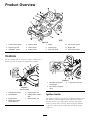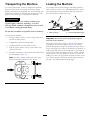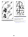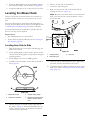
1
Form No. 3393-645 Rev B
TimeCutter® SW 3200 Riding
Mower
Model No. 74670—Serial No. 315000001 and Up
g027913
Register at www.Toro.com.
Original Instructions (EN)
*3393-645* B
This product complies with all relevant European directives;
for details, please see the separate product specific Declaration
of Conformity (DOC) sheet.
1
Gross Horsepower
The gross or net horsepower of this engine was laboratory
rated by the engine manufacturer in accordance with the
Society of Automotive Engineers (SAE) J1940. As configured
to meet safety, , and operating requirements, the actual engine
torque on this class of mower will be significantly lower.
Go to www.Toro.com to view specifications on your mower
model.
G014523
Figure 1
Under the seat
Important: This engine is not equipped with a spark
arrester muffler. It is a violation of California Public
Resource Code Section 4442 to use or operate the engine
on any forest-covered, brush-covered, or grass-covered
land. Other states or federal areas may have similar laws.
1. Model and serial number plate
Write the product model and serial numbers in the space
below:
Model No.
Introduction
Serial No.
This machine is a ride-on, rotary-blade intended to be used
by homeowners in residential applications. It is primarily
designed for cutting grass on well-maintained lawns. It is not
designed for cutting brush, mowing grass and other growth
alongside highways, or for agricultural uses.
This manual identifies potential hazards and has safety
messages identified by the safety alert symbol (Figure 2),
which signals a hazard that may cause serious injury or death
if you do not follow the recommended precautions.
Read this information carefully to learn how to operate and
maintain your product properly and to avoid injury and
product damage. You are responsible for operating the
product properly and safely.
Figure 2
You may contact Toro directly at www.Toro.com for product
safety and operation training materials, accessory information,
help finding a dealer, or to register your product.
1. Safety alert symbol
This manual uses 2 words to highlight information.
Important calls attention to special mechanical information
and Note emphasizes general information worthy of special
attention.
Whenever you need service, genuine Toro parts, or additional
information, contact an Authorized Service Dealer or Toro
Customer Service and have the model and serial numbers of
your product ready. Figure 1 identifies the location of the
model and serial numbers on the product. Write the numbers
in the space provided.
© 2015—The Toro® Company
8111 Lyndale Avenue South
Bloomington, MN 55420
2
Contact us at www.Toro.com.
Printed in the USA.
All Rights Reserved
Contents
Cleaning ...................................................................44
Cleaning Under the Front of the Machine...................44
Washing the Underside of the Mower ........................44
Storage ........................................................................45
Cleaning and Storing the Machine .............................45
Troubleshooting ...........................................................47
Schematics ...................................................................49
Safety ........................................................................... 4
Safe Operating Practices........................................... 4
Toro Mower Safety .................................................. 6
Model 74670........................................................... 7
Slope Indicator ....................................................... 8
Safety and Instructional Decals ................................. 9
Product Overview .........................................................13
Controls ...............................................................13
Operation ....................................................................15
Adding Fuel...........................................................15
Checking the Engine-oil Level..................................16
Breaking in a New Machine......................................16
Think Safety First ...................................................17
Starting the Engine .................................................19
Operating the Parking Brake (SmartPark™) ................19
Operating the Blades...............................................19
Stopping the Engine ...............................................20
Driving the Machine ...............................................20
Stopping the Machine .............................................21
Mowing in Reverse .................................................21
Adjusting the Height-of-Cut ....................................21
Positioning the Seat ................................................22
Positioning the Steering Wheel .................................22
Pushing the Machine by Hand ..................................22
Converting to Side Discharge ...................................23
Transporting the Machine........................................24
Loading the Machine ..............................................24
Operating Tips ......................................................26
Maintenance .................................................................27
Recommended Maintenance Schedule(s) ......................27
Premaintenance Procedures ........................................27
Raising the Seat ......................................................27
Releasing the Mower-Deck Curtain ...........................27
Raising the Front of the Machine ..............................28
Lubrication ...............................................................28
Greasing the Bearings .............................................28
Engine Maintenance ..................................................29
Servicing the Air Cleaner .........................................29
Servicing the Engine Oil..........................................30
Servicing the Spark Plug ..........................................32
Cleaning the Blower Housing ...................................33
Fuel System Maintenance ...........................................34
Replacing the In-line Fuel Filter ................................34
Electrical System Maintenance ....................................34
Charging the Battery ...............................................34
Servicing the Fuses .................................................36
Drive System Maintenance .........................................36
Checking the Tire Pressure ......................................36
Releasing the Electric Brake .....................................37
Mower Maintenance ...................................................37
Servicing the Cutting Blades.....................................37
Leveling the Mower Deck ........................................40
Removing the Mower Deck .....................................41
Servicing the Mower Belt.........................................42
Installing the Mower Deck.......................................43
Replacing the Grass Deflector ..................................43
3
Preparation
Safety
• Evaluate the terrain to determine what accessories and
This machine has been designed in accordance with EN ISO
5395:2013.
Improperly using or maintaining this mower can result
in injury. To reduce the potential for injury, comply with
these safety instructions.
•
Toro designed and tested this mower for reasonably safe
service; however, failure to comply with the following
instructions may result in personal injury.
•
To ensure maximum safety, best performance, and
to gain knowledge of the product, it is essential that
you and any other operator of the mower read and
understand the contents of this manual before the
engine is ever started. Pay particular attention to the
safety alert symbol (Figure 2) which means Caution,
Warning, or Danger—“personal safety instruction.”
Read and understand the instruction because it has to
do with safety. Failure to comply with the instruction
may result in personal injury.
•
Safe Operating Practices
•
Training
• Read the Operator's Manual and other training material.
attachments are needed to properly and safely perform
the job. Only use accessories and attachments approved
by the manufacturer.
Wear appropriate clothing; including a hard hat,
substantial, slip-resistant footwear, long pants, gloves, and
hearing protection.
Important: Long hair, loose clothing or jewelry may
get tangled in moving parts.
Inspect the area where the equipment is to be used and
ensure that all objects are removed from the machine
before use.
Use extra care when handling fuels. They are flammable
and vapors are explosive.
– Use only an approved container.
– Do not remove the fuel cap or add fuel with the
engine running. Allow the engine to cool before
refueling. Do not smoke near the machine when the
engine is running.
– Do not refuel or drain the machine indoors.
Check that the operator's presence controls, safety
switches, and shields are attached and functioning
properly. Do not operate the machine unless they are
functioning properly.
Operation
Note: If the operator(s) or mechanic(s) cannot read the
manual language, it is the owner's responsibility to explain
this material to them.
• Lightning can cause severe injury or death. If lightning
• Become familiar with the safe operation of the equipment,
•
operator controls, and safety signs.
• All operators and mechanics should be trained. The
owner is responsible for training the users.
•
• Never let children or untrained people operate or service
the equipment.
•
Note: Local regulations may restrict the age of the
operator.
•
• The owner/user can prevent and is responsible for
accidents or injuries occurring to himself or herself, other
people, or damage to property.
•
•
•
•
•
4
is seen, or thunder is heard in the area, do not operate
the machine; seek shelter.
Do not operate the engine in a confined space where
dangerous carbon monoxide and other exhaust gasses
can collect.
Only operate in well-lit areas, keeping away from holes
and hidden hazards.
Ensure that all drives are in neutral and that the parking
brake is engaged before starting engine. Only start the
engine from the operator’s position.
Slow down and use extra care on hillsides. Be sure to
travel side to side on hillsides. Turf conditions can affect
the stability of the machine. Use caution while operating
near drop-offs.
Slow down and use caution when making turns and when
changing directions on slopes.
Do not raise the mower deck with the blades running.
Do not operate the machine without the PTO shield or
other guards securely in place. Be sure all interlocks are
attached, adjusted properly, and functioning properly.
Do not operate with the discharge deflector raised,
removed or altered, unless using a grass catcher.
Do not change the engine governor setting or overspeed
the engine.
Maintenance and Storage
• Stop on level ground, disengage drives, engage the
•
•
•
•
•
•
•
•
•
parking brake (if provided), shut off the engine before
leaving the operator's position for any reason, including
emptying the catchers or unclogging the chute.
Stop equipment and inspect the blades after striking
objects or if an abnormal vibration occurs. Make the
necessary repairs before resuming operations.
Keep your hands and feet away from the cutting unit.
Look behind and down before backing up to ensure a
clear path.
Keep pets and bystanders away from an operating
machine.
Slow down and use caution when making turns and
crossing roads and sidewalks. Stop the blades if you are
not mowing.
Be aware of the mower-discharge direction and do not
point it at anyone.
Do not operate the mower under the influence of alcohol
or drugs.
Use care when loading or unloading the machine into
or from a trailer or truck.
Use care when approaching blind corners, shrubs, trees,
or other objects that may obscure vision.
• Disengage drives, set the parking brake, stop the engine,
and remove the key or disconnect spark-plug wire. Wait
for all movement to stop before adjusting, cleaning, or
repairing.
• Clean grass and debris from the cutting unit, drives,
mufflers, and engine to help prevent fires.
• Clean up oil or fuel spillage.
• Let the engine cool before storing.
• Do not store fuel near flames or drain indoors.
• Do not allow untrained personnel to service machine.
• Use jack stands to support components when required.
• Carefully release pressure from components with stored
energy.
• Disconnect the battery or remove the spark-plug wire
before making any repairs. Disconnect the negative
terminal first and the positive terminal last. Reconnect
the positive first and negative last.
• Use care when checking the blades. Wrap the blade(s) or
wear gloves, and use caution when servicing them. Only
replace blades; do not straighten or weld them.
• Keep hands and feet away from moving parts. If possible,
Safe Handling of Fuels
do not make adjustments with the engine running.
• To avoid personal injury or property damage, use
•
•
•
•
•
•
•
•
•
•
•
• Keep all parts in good working condition and all hardware
extreme care in handling gasoline. Gasoline is extremely
flammable and the vapors are explosive.
Extinguish all cigarettes, cigars, pipes, and other sources
of ignition.
Use only an approved fuel container.
Do not remove the fuel cap or add fuel with the engine
running.
Allow the engine to cool before fueling.
Do not fuel the machine indoors.
Do not store the machine or fuel container where there
is an open flame, spark, or pilot light such as on a water
heater or on other appliances.
Do not fill containers inside a vehicle, on a truck, or on a
trailer bed with a plastic liner. Always place containers on
the ground away from your vehicle before filling.
Remove equipment from the truck or trailer and fuel it
on the ground. If this is not possible, then add fuel with
such equipment as a portable container, rather than from
a fuel dispenser nozzle.
Keep the nozzle in contact with the rim of the fuel tank
or container opening at all times until fueling is complete.
Do not use a nozzle lock open device.
If fuel is spilled on clothing, change your clothing
immediately.
Do not overfill fuel tank. Replace fuel cap and tighten
securely.
tightened. Replace all worn or damaged decals.
Hauling
• Use care when loading or unloading the machine into a
trailer or a truck.
• Use full-width ramps for loading machine into a trailer
or a truck.
• Tie the machine down securely using straps, chains, cable,
or ropes. Both front and rear straps should be directed
down and outward from the machine.
5
Toro Mower Safety
Slope Operation
The following list contains safety information specific to Toro
products and other safety information you must know.
All slopes and ramps require extra caution. If you feel uneasy
on a slope, do not mow it.
• Remove obstacles such as rocks, tree limbs, etc. from the
This product is capable of amputating hands and feet, and
throwing objects. Always follow all safety instructions to
avoid serious injury or death.
mowing area.
• Watch for holes, ruts or bumps.
Note: Tall grass can hide obstacles.
This product is designed for cutting and recycling grass, or,
when equipped with a grass bagger, for catching cut grass.
Any use for purposes other than these could prove dangerous
to the user and bystanders.
• Use caution near drop-offs, ditches, or embankments.
General Operation
• Use extra care with grass catchers or other attachments.
Note: The machine could suddenly turn over if a wheel
goes over the edge of a cliff or ditch, or if an edge caves in.
Note: These can change the stability of the machine.
• Be sure that the area is clear of bystanders before mowing.
Stop the machine if anyone enters the area.
•
•
•
•
• Do not touch equipment or attachment parts which may
be hot from operation. Allow all of the parts to cool
before attempting to maintain, adjust, or service the
machine.
• Use only Toro-approved attachments. Warranty may be
Keep all movement on slopes slow and gradual.
Do not make sudden changes in speed or direction.
Mow slopes side to side.
Do not mow slopes greater than 15 degrees.
Towing Safety
voided if used with any unapproved attachments.
• Do not attach towed equipment except at the hitch point.
• Follow the attachment manufacturer's recommendation
• Check carefully for overhead clearances (i.e. branches,
doorways, electrical wires, etc.) before operating under
any objects, and do not contact them.
for weight limits for towed equipment and towing on
slopes. Towed weight must not exceed the weight of the
machine, operator, and ballast. Use counterweights or
wheel weights as described in the attachment, or in the
pulling machine Operator’s Manual.
• Slow down the machine before making turns and use
extra caution.
• Use caution when riding the platform over curbs, rocks,
roots, or other obstructions.
• Never allow children or others in or on towed equipment.
• On slopes, the weight of the towed equipment may cause
• Look behind and down before backing up to ensure a
clear path. Use extra care when operating the machine
in reverse.
loss of traction, increased risk of rollover, and loss of
control. Reduce the towed weight and slow down.
• Do not jerk the steering wheel; use a steady motion.
• Stopping distance increases with the weight of the towed
• When loading or unloading the machine, use one
load. Travel slowly and allow extra distance to stop.
full-width ramp that is wide enough to extend beyond
the width of the machine.
• Make wide turns to keep the attachment clear of the
machine.
• Do not carry passengers.
Service
• Do not carry equipment on the machine.
• Do not store the machine or a fuel container inside where
there is an open flame, such as near a water heater or
furnace.
• Keep the nuts and bolts tight, especially the
blade-attachment bolts.
• Never remove or tamper with safety devices. Check their
proper operation regularly. Never do anything to interfere
with the intended function of a safety device or to reduce
the protection provided by a safety device.
• To best protect your investment and maintain optimal
performance of your Toro equipment, count on Toro
genuine parts. When it comes to reliability, Toro delivers
replacement parts designed to the exact engineering
6
specifications of our equipment. For peace of mind, insist
on Toro genuine parts.
• Check the brake operation frequently. Adjust and service
the brake as required.
Model 74670
Sound Pressure
This unit has a sound pressure level at the operator’s ear of 87
dBA, which includes an Uncertainty Value (K) of 1 dBA.
Sound power level was determined according to the
procedures outlined in ISO 11094.
Sound Power
This unit has a guaranteed sound power level of 100 dBA,
which includes an Uncertainty Value (K) of 1 dBA.
Sound pressure level was determined according to the
procedures outlined in EN ISO 5395:2013.
Hand/Arm Vibration
Measured vibration level for left hand = 1.7 m/s2
Measured vibration level for right hand = 1.8 m/s2
Uncertainty Value (K) = 0.9 m/s2
Measured values were determined according to the procedures
outlined in EN ISO 5395:2013.
Whole Body Vibration
Measured vibration level = 0.51 m/s2
Uncertainty Value (K) = 0.26 m/s2
Measured values were determined according to the procedures
outlined in EN ISO 5395:2013 (Riding and Stand-ons).
7
Slope Indicator
G011841
Figure 3
This page may be copied for personal use.
1. The maximum slope you can safely operate the machine on is 15 degrees. Use the slope chart to determine the degree of slope
of hills before operating. Do not operate this machine on a slope greater than 15 degrees. Fold along the appropriate line
to match the recommended slope.
2. Align this edge with a vertical surface, a tree, building, fence pole, etc.
3. Example of how to compare slope with folded edge.
8
Safety and Instructional Decals
Safety decals and instructions are easily visible to the operator and are located near any area of potential
danger. Replace any decal that is damaged or lost.
93-7009
1. Warning—don't operate the mower with the deflector up or
removed; keep the deflector in place.
2. Cutting/dismemberment hazard of hand or foot, mower
blade—stay away from moving parts.
106-8717
1. Read the instructions before servicing or performing
maintenance.
2. Check tire pressure every 25 operating hours.
3. Grease every 25 operating hours.
4. Engine
120-5469
1. Height-of-cut
110-6691
1. Thrown object hazard—keep bystanders a safe distance
from the machine.
2. Thrown object hazard, mower—do not operate without the
deflector, discharge cover, or grass collection system in
place.
3. Cutting/dismemberment of hand or foot—stay away from
moving parts.
121-2989
1. Bypass lever position for
pushing the machine
114-1606
1. Entanglement hazard, belt—keep all guards in place.
9
2. Bypass lever position for
operating the machine
Manufacturer's Mark
1. Indicates the blade is identified as a part from the original
machine manufacturer.
131-3665
1. Blade spinning
3. Read the Operator's
Manual.
2. Reverse
131-3620
1. Pedal position—forward
3. Pedal position—reverse
2. Pedal position—neutral
131-3955
1. On
2. Off
131-4036
1. Maximum drawbar pull 80
lbs (36 kg)
131-3621
1. Crushing/dismemberment hazard of bystanders—keep
bystanders away from the machine; do not start the
machine with bystanders nearby.
10
2. Read the Operator's
Manual.
132-0870
1. Warning—read the Operator's Manual.
3. Bodily harm hazard—no riders; look
behind you when mowing in reverse.
5. Ramp tipping hazard—when loading
onto a trailer, do not use dual ramps;
only use a single ramp wide enough
for the machine and that has an incline
less than 15 degrees; back up the
ramp (in reverse) and drive forward off
the ramp.
2. Cutting hazard of hand, mower blade;
pinching hazard of hand, belt—keep
hands and feet away from moving
parts; keep all guards and shields in
place.
4. Thrown object hazard—keep
bystanders away from the machine;
remove debris from the area before
mowing; keep the deflector shield
down.
6. Tipping hazard on slopes—do not
make sharp, quick turns; do not use
slopes greater than 15 degrees.
11
Battery Symbols
Some or all of these symbols are on your battery
1. Explosion hazard
6. Keep bystanders a safe
distance from the battery.
2. No fire, open flame, or
smoking.
7. Wear eye protection;
explosive gases can
cause blindness and other
injuries
3. Caustic liquid/chemical
burn hazard
4. Wear eye protection
8. Battery acid can cause
blindness or severe burns.
9. Flush eyes immediately
with water and get medical
help fast.
5. Read the Operator's
Manual.
10. Contains lead; do not
discard.
121-0771
1. Choke
2. Fast
4. Slow
5. Power take-off (PTO), Blade control switch
3. Continuous variable setting
12
Product Overview
6
4
7
5
8
3
2
1
9
10
11
12
g027912
Figure 4
1. Traction-control pedal
4. Steering wheel
7. Engine
2. Height-of-cut lever
5. Control panel
8. Fuel-tank cap
11. Mower deck
3. SmartPark™ switch
6. Operator seat
9. Rear drive wheel
12. Front caster wheels
10. Key Choice® control
Controls
Become familiar with all controls in Figure 4 and Figure 5
before you start the engine and operate the machine.
5
6
7
Figure 6
1. Operating–in–Reverse
warning light
g027892
3. Fuel-presence window
2. Key Choice key (blue in
color)
Figure 5
Control Panel
1. Parking brake switch
5. Parking brake—On
2. Throttle/Choke
6. Parking brake indicator
light
Ignition Switch
3. Ignition switch
7. Parking brake—Off
The ignition switch has 3 positions—Off, Run and Start. The
key will turn to Start and move back to Run upon release.
Turning the key to the Off position will stop the engine;
however, always remove the key when leaving the machine
to prevent someone from accidentally starting the engine
(Figure 5).
4. Blade-control switch
(power take-off)
13
Throttle/Choke Control
The throttle and choke are combined into one control lever.
The throttle controls the engine speed and it has a continuous
variable setting from Slow to Fast. Engage the choke by
moving the lever past the Fast setting until it stops (Figure 5).
Blade-Control Switch (Power Take-off)
The blade-control switch, (PTO), engages and disengages
power to the mower blades (Figure 5).
Fuel-Presence Window
The fuel window located on the left-hand side of the machine,
can be used to verify the presence of gasoline in the tank
(Figure 6).
Height-of-Cut Lever
The height-of-cut lever allows you to lower and raise the deck
from the seated position. When you raise the lever (toward
you), the deck is raised from the ground, and when you
lower it (away from you), it lowers to the ground. Adjust the
height-of-cut only while the machine is not moving (Figure
14).
Key Choice® Switch
This switch allows you to mow in reverse when it is activated.
To activate it, turn the switch to on and release it after the
PTO is engaged. To deactivate it, disengage the power
take-off (PTO) (Figure 6).
Operating–in–Reverse Warning Light
The Operating–in–Reverse warning light will illuminate
whenever the KeyChoice key is used to deactivate the
operating–in–reverse interlock. It is a reminder that the
interlock system is deactivated. The light goes out whenever
the PTO is disengaged or the engine is shut off. When the
light is on, look behind and use extra caution when backing.
SmartPark™ Switch
The parking brake is activated electronically.
Engage the parking brake by one of the following actions:
• Pressing the SmartPark™ switch to the On position
(Figure 5).
• The parking brake engages automatically when the
operator leaves the seat and the traction control pedal
is in neutral position.
• The parking brake automatically engages 5 to 6 seconds
after the ignition switch is turned to the Off position (if
not already engaged).
To disengage the parking brake, press the Smartpark switch
to the Off position with the key in the run position.
14
Operation
Note: Determine the left and right sides of the machine from the normal operating position.
DANGER
Adding Fuel
In certain conditions during fueling, static
electricity can be released causing a spark which
can ignite the gasoline vapors. A fire or explosion
from gasoline can burn you and others and can
damage property.
• Always place gasoline containers on the ground
away from your vehicle before filling.
• Do not fill gasoline containers inside a vehicle or
on a truck or trailer bed because interior carpets
or plastic truck bed liners may insulate the
container and slow the loss of any static charge.
• When practical, remove gas-powered equipment
from the truck or trailer and refuel the equipment
with its wheels on the ground.
• If this is not possible, then refuel such
equipment on a truck or trailer from a portable
container, rather than from a gasoline dispenser
nozzle.
• If a gasoline dispenser nozzle must be used,
keep the nozzle in contact with the rim of the
fuel tank or container opening at all times until
fueling is complete.
• For best results, use only clean, fresh (less than 30 days
old), unleaded gasoline with an octane rating of 87 or
higher ((R+M)/2 rating method).
• Ethanol: Gasoline with up to 10% ethanol (gasohol)
or 15% MTBE (methyl tertiary butyl ether) by volume
is acceptable. Ethanol and MTBE are not the same.
Gasoline with 15% ethanol (E15) by volume is not
approved for use. Never use gasoline that contains
more than 10% ethanol by volume, such as E15
(contains 15% ethanol), E20 (contains 20% ethanol), or
E85 (contains up to 85% ethanol ). Using unapproved
gasoline may cause performance problems and/or engine
damage which may not be covered under warranty.
• Do not use gasoline containing methanol.
• Do not store fuel either in the fuel tank or fuel containers
over the winter unless a fuel stabilizer is used.
• Do not add oil to gasoline.
DANGER
In certain conditions, gasoline is extremely
flammable and highly explosive. A fire or explosion
from gasoline can burn you and others and can
damage property.
• Fill the fuel tank outdoors, in an open area,
when the engine is cold. Wipe up any gasoline
that spills.
WARNING
Gasoline is harmful or fatal if swallowed. Long-term
exposure to vapors can cause serious injury and
illness.
• Avoid prolonged breathing of vapors.
• Keep face away from nozzle and gas tank or
conditioner bottle opening.
• Avoid contact with skin; wash off spillage with
soap and water.
• Never fill the fuel tank inside an enclosed trailer.
• Do not fill the fuel tank completely full. Add
gasoline to the fuel tank until the level is 6 to 13
mm (1/4 to 1/2 inch) below the bottom of the
filler neck. This empty space in the tank allows
gasoline to expand.
• Never smoke when handling gasoline, and stay
away from an open flame or where gasoline
fumes may be ignited by a spark.
Using Stabilizer/Conditioner
Use a fuel stabilizer/conditioner in the machine to provide
the following benefits:
• Keeps gasoline fresh during storage of 90 days or less.
For longer storage it is recommended that the fuel tank
be drained.
• Cleans the engine while it runs
• Eliminates gum-like varnish buildup in the fuel system,
which causes hard starting
• Store gasoline in an approved container and
keep it out of the reach of children. Never buy
more than a 30-day supply of gasoline.
• Do not operate without entire exhaust system in
place and in proper working condition.
Important: Do not use fuel additives containing
methanol or ethanol.
15
break-in time for new machines to develop full power and
best performance.
Add the correct amount of gas stabilizer/conditioner to
the gas.
Note: A fuel stabilizer/conditioner is most effective
when mixed with fresh gasoline. To minimize the chance
of varnish deposits in the fuel system, use fuel stabilizer
at all times.
Filling the Fuel Tank
Note: Ensure that the engine is shut off and the motion
controls are in the parked position.
Note: You can use the fuel window to verify the presence of
gasoline before filling the tank (Figure 7).
Important: Do not overfill fuel tank. Fill the fuel tank
to the bottom of the filler neck. The empty space in the
tank allows the fuel to expand. Overfilling may result in
fuel leakage, damage to the engine, or damage to the
emissions system.
A
B
C
D
E
g027243
Figure 7
Checking the Engine-oil Level
Before you start the engine and use the machine, check
the oil level in the engine crankcase; refer to Checking the
Engine-Oil Level (page 30).
Breaking in a New Machine
New engines take time to develop full power. Mower decks
and drive systems have higher friction when new, placing
additional load on the engine. Allow 40 to 50 hours of
16
Think Safety First
CAUTION
This machine produces sound levels in excess of 85
dBA at the operators ear and can cause hearing loss
through extended periods of exposure.
Operating Safety
Please carefully read all of the safety instructions and decals
in the safety section. Knowing this information could help
you, your family, pets, or bystanders avoid injury.
Wear hearing protection when operating this
machine.
DANGER
The use of protective equipment for eyes, ears, hands, feet,
and head is recommended.
Mowing on wet grass or steep slopes can cause
sliding and loss of control.
1
Wheels dropping over edges can cause rollovers,
which may result in serious injury, death, or
drowning.
2
A loss of traction is a loss of steering control.
G009027
Figure 9
To avoid loss of control and possibility of rollover:
• Do not mow near drop-offs or near water.
• Do not mow slopes greater than 15 degrees.
• Reduce the speed and use extreme caution on
slopes.
• When mowing slopes, gradually work from
lower to higher areas on the incline.
• Avoid sudden turns or rapid speed changes.
• Turn up, into an incline when changing
directions on slopes. Turning down the slope
reduces traction.
• Attachments change the handling characteristics
of the machine. Use extra caution when using
attachments with the machine.
1. Wear safety glasses
g027830
Figure 8
1. Safe zone—use the
TimeCutter here
2. Use a walk-behind mower
and/or hand trimmer near
drop-offs and water.
3. Water
17
2. Wear hearing protection
Understanding the Safety-interlock
System
Note: The engine should remain running.
9. Return to the seat, disengage the parking brake by
pushing the SmartPark switch to the Off position.
WARNING
Note: The engine should remain running.
If safety-interlock switches are disconnected or
damaged, the machine could operate unexpectedly
causing personal injury.
10. Raise from the seat.
Note: The brake should automatically engage and the
engine should remain running.
• Do not tamper with the interlock switches.
11. Return to the seat, engage the blades by pulling up on
the blade-control switch.
• Check the operation of the interlock switches
daily, and replace any damaged switches before
operating the machine.
12. Raise from the seat.
Note: The blades should disengage and the engine
should remain running.
The safety-interlock system is designed for the following:
• To prevent the engine from starting unless the traction
13. Return to the seat, and pull the blade control switch up.
pedal is in the neutral position.
Note: The blades should engage.
• To automatically ensure that the parking brake is engaged
14. Push down on the blade-control switch.
and the PTO is off when starting.
Note: The blades should disengage.
• To stop the engine whenever the traction pedal is not in
the neutral position and you rise from the seat.
15. Engage the blades by pulling up on the blade-control
switch.
• To automatically engage the parking brake and disengage
the PTO, when you rise out of the seat with the traction
pedal in the neutral position.
16. Move traction pedal to reverse.
Note: The blades should disengage.
• To stop the engine whenever the parking brake is not
engaged and you rise from the seat.
17. Engage the blades by pulling up on the blade-control
switch.
Testing the Safety-interlock System
18. Turn the Key Choice switch to On and release.
1. While sitting on the seat, move the blade-control
switch to Off.
Note: The operating in reverse light should illuminate.
19. Move the traction pedal to reverse.
2. Turn the ignition key to the Start position.
Note: The blades should remain engaged.
Note: The starter should crank.
20. Push the PTO switch to the off position.
3. Push the SmartPark switch to the Off position.
Note: The blades should turn off and the reverse
warning light should turn off.
Note: The brake should disengage, and the brake light
should turn off.
21. Engage the parking brake by pushing SmartPark switch
to the On position.
4. With brake disengaged and traction pedal in neutral,
turn the ignition switch to the Start position.
Note: The brake should engage and the brake light
should be on.
Note: The brake should automatically engage, the
engine should crank, and the brake light will turn on.
22. Push and release the traction pedal in either the forward
or reverse direction.
5. Engage the PTO by pulling up on the blade-control
switch.
Note: The brake should disengage and the brake light
should turn off.
6. Ensure the traction pedal is in neutral and turn ignition
switch to the Start position.
23. Raise from the seat, and push the traction pedal to
either the forward or reverse direction.
Note: The PTO should disengage and the engine
should crank.
Note: The engine should kill.
7. Ensure the traction control pedal is in the neutral
position and start the engine.
8. Raise from the seat.
18
Starting the Engine
• Tap the traction-control pedal forward or reverse.
Note: It may be necessary to hold the lever against the stop,
in the choke position, while trying to start the engine.
• Pressing the brake switch to the Off position (Figure 5).
Note: A warm or hot engine may not require choking.
Operating the Blades
Important: Do not engage the starter for more than
5 seconds at a time. Engaging the starter motor for
more than 5 seconds can damage the starter motor. If
the engine fails to start, wait 10 seconds before operating
the engine starter again.
The blade-control switch, represented by a power take-off
(PTO) symbol, engages and disengages power to the mower
blades. This switch controls power to any attachments that
draw power from the engine, including the mower deck and
cutting blades.
A
B
Engaging the Blades
Important: Do not engage the blades when parked in
tall grass. Belt or clutch damage can occur.
Note: Always engage the blades with the throttle in the
Fast position.
C
D
E
F
g027901
g027899
Figure 11
Figure 10
Disengaging the Blades
Operating the Parking Brake
(SmartPark™)
The parking brake is activated electronically.
Engage the parking brake by one of the following actions:
• Pressing the SmartPark™ switch to the On position
(Figure 5).
g027247
• The parking brake engages automatically when the
Figure 12
operator leaves the seat and the traction control pedal is
in the neutral position.
1. Control panel
• The parking brake automatically engages 5 to 6 seconds
after the ignition switch is turned to the Off position (if
not already engaged).
Disengage the parking brake by one of the following actions:
19
2. Blade-control switch—Off
Stopping the Engine
1. Disengage the blades by pushing the blade-control
switch to Off (Figure 12).
2. Move the throttle lever to the Slow position.
Note: Run it at idle speed for approximately one
minute.
3. Turn the ignition key to Off and remove the key.
Figure 13
Driving the Machine
1. Forward
2. Traction-control pedal
This machine has the characteristics of both a garden tractor
and a zero-turn machine. Like a garden tractor, the machine
has a foot pedal that controls the forward and reverse motion
along with the speed, and it has a steering wheel that controls
the direction and the turning radius. Like a zero-turn machine,
the rear drive wheels operate independently of each other,
enabling you to make sharp turns and to turn in different
directions quickly. These characteristics vastly improve the
maneuverability of the machine, but they may also require
you to practice driving if you are unfamiliar with this type of
machine.
3. Backward
3. To slow down, release the pressure on the
traction-control pedal.
WARNING
The machine can spin very rapidly. The operator
may lose control of the machine and cause personal
injury or damage to the machine.
• Use caution when making turns.
• Slow the machine down before making sharp
turns.
The throttle control regulates the engine speed as measured
in rpm (revolutions per minute). Placing the throttle control
in the Fast position can be best for performance. For most
applications, operating in the full-throttle position is desirable.
Driving Forward or Backward
1. Move the throttle to the fast position.
2. Place your foot onto the traction-control pedal and
slowly press the top of the pedal to go forward, or
press on the bottom of the pedal to move backward
(Figure 13).
Note: The farther you move the pedal in either
direction, the faster the machine will move in that
direction.
20
Stopping the Machine
4. Perform the mowing.
To stop the machine, release the traction-control pedal,
disengage the blade-control switch, ensure the throttle is
between the fast and slow positions, set the parking brake and
turn the ignition key to off.
5. When finished mowing, remove the KeyChoice key
(Figure 6).
Note: Once you deactivate the interlock, it stays in
this mode—with your mower blade or PTO powered
attachment operating whenever you back up—and the
console light stays on until you either disengage the
PTO or turn off the engine.
Note: Remember to remove the key from the ignition switch.
WARNING
Children or bystanders may be injured if they
move or attempt to operate the mower while it is
unattended.
Adjusting the Height-of-Cut
Note: The transport position is the highest height-of-cut
position or cutting height 115 mm (4.5 inches) as shown in
Figure 14.
Always remove the ignition key and set the parking
brake when leaving the machine unattended, even
if just for a few minutes.
Mowing in Reverse
The machine has an interlock feature that prevents the mower
deck from mowing while the machine is traveling in reverse.
If you shift into reverse with the PTO engaged, the PTO
will stop. If you need to mow while in reverse gear, you can
temporarily deactivate this interlock.
Note: Do not mow while backing up unless it is absolutely
necessary.
DANGER
A child or bystander could be backed over by a
riding mower with blades engaged and cause
serious personal injury or death.
• Do not mow in reverse unless absolutely
necessary.
• Always look backward and down before backing
up.
• Use the KeyChoice switch only if you are certain
no children or other bystanders will appear in
the mowing area.
• Always remove both the ignition and KeyChoice
keys and put them in a safe place out of the
reach of children or unauthorized users when
leaving the unit unattended.
Figure 14
If you are certain that you can safely mow or operate an
attachment in reverse, complete the following procedure:
1. Insert the KeyChoice key into the KeyChoice switch
(Figure 6).
2. Engage the PTO.
3. Turn the KeyChoice key clockwise until it stops and
release it.
Note: A red light illuminates on the console to serve
as a reminder that the interlock has been deactivated.
21
Pushing the Machine by Hand
Positioning the Seat
A
Important: Always push the machine by hand. Do not
tow the machine, because damage may occur.
B
This machine has an electric-brake mechanism, and to push
the machine, the ignition key needs to be in the Run position.
The battery needs to be charged and functioning for the
electric brake to be disengage.
Pushing the Machine
1. Park the machine on a level surface, and disengage the
blade-control switch.
C
2. Set the parking brake, stop the engine, and wait for
all moving parts to stop before leaving the operating
position.
3. Locate the bypass levers on the frame on both sides of
the engine.
4. Move the bypass levers forward through the key hole
and down to lock them in place (Figure 17).
g027249
Note: Ensure this is done for each lever.
Figure 15
5. Turn the ignition key on and disengage the parking
brake.
Note: Do not start the machine.
Positioning the Steering Wheel
Note: The machine is now able to be pushed by hand.
The steering wheel has 3 positions for operation and one,
full-up position. Use the full-up position for stepping on and
off the machine and getting out of the seat. When operating
the machine, position the steering wheel where you have the
best control of the machine and are most comfortable.
3
1. Press your foot onto the steering-column release lever.
2. Position the steering wheel to the desired position
(Figure 16).
A
1
2
g017303
Figure 17
B
1. Bypass-lever locations
3. Lever position for pushing
the machine
2. Lever position for
operating the machine
6. When finished, ensure that the key has been returned to
the Stop position to avoid draining the battery charge.
g027751
Figure 16
Note: If the machine fails to move, the electric brake may
still be engaged. If necessary, the electric brake can be released
manually; refer to Releasing the Electric Brake (page 37).
22
Operating the Machine
Installing the Discharge Cover for
Mulching
Move the bypass levers rearward through the key hole and
down to lock them in place as shown in Figure 17.
1. Park the machine on a level surface and disengage the
blade-control switch.
Note: Ensure this is done for each lever.
2. Move the motion-control levers outward to park
position, stop the engine, remove the key, and wait for
all moving parts to stop before leaving the operating
position.
Converting to Side Discharge
This mower deck has the option to be operated in the
side-discharge mode. Remove the discharge cover for
operating in the side-discharge mode.
3. Lift the grass deflector and place the discharge cover
over the opening onto the lower lip of the mower and
slide it into the front hinge (Figure 18).
Removing the Discharge Cover for Side
Discharge
4. Slide the hinge pin through the hinge (Figure 18).
5. Secure the discharge cover to the mower with the wing
nut (Figure 18).
1. Park the machine on a level surface and disengage the
blade-control switch.
6. Lower the grass deflector over the discharge opening.
2. Move the motion-control levers outward to park
position, stop the engine, remove the key, and wait for
all moving parts to stop before leaving the operating
position.
3. Remove the wing nut and bolt securing the cover in
place (Figure 18).
Note: Retain all of the parts for future use.
Figure 18
1. Grass deflector
4. Hinge pin
2. Discharge cover
5. Wing nut
3. Lower lip
4. Remove the hinge pin securing the cover to the deck
(Figure 18).
5. Lift the cover out and away from the deck.
6. Lower the grass deflector over the discharge opening.
Important: Ensure that the mower has a hinged
grass deflector that disperses clippings to the side
and down toward the turf, while in side discharge
mode.
23
Transporting the Machine
Loading the Machine
Use a heavy-duty trailer or truck to transport the machine.
Ensure that the trailer or truck has all necessary brakes,
lighting, and marking as required by law. Please carefully read
all the safety instructions. Knowing this information could
help you, your family, pets, or bystanders avoid injury.
Use extreme caution when loading or unloading machines
onto a trailer or a truck. Use a full-width ramp that is wider
than the machine for this procedure. Back up ramps and
drive forward down ramps (Figure 20).
WARNING
Driving on the street or roadway without turn
signals, lights, reflective markings, or a slow
moving vehicle emblem is dangerous and can lead
to accidents causing personal injury.
Figure 20
Do not drive machine on a public street or roadway.
1. Back up ramps
2. Drive forward down ramps
To transport the machine:
1. If using a trailer, connect it to the towing vehicle and
connect the safety chains.
Important: Do not use narrow individual ramps for
each side of the machine.
2. If applicable, connect the trailer brakes.
Ensure the ramp is long enough so that the angle with the
ground does not exceed 15 degrees (Figure 21). On flat
ground, this requires a ramp to be at least four times (4X) as
long as the height of the trailer or truck bed to the ground. A
steeper angle may cause mower components to get caught as
the unit moves from the ramp to the trailer or truck. Steeper
angles may also cause the machine to tip or lose control. If
loading on or near a slope, position the trailer or truck so that
it is on the down side of the slope and the ramp extends up
the slope. This will minimize the ramp angle.
3. Load the machine onto the trailer or truck.
4. Stop the engine, remove the key, set the brake, and
close the fuel valve.
5. Tie down the machine near the front caster wheels and
the rear bumper (Figure 19).
Note: Avoid the steering components when tying
down the machine at the front caster wheels.
Figure 19
24
WARNING
1
Loading a machine onto a trailer or truck increases
the possibility of tip-over and could cause serious
injury or death.
• Use extreme caution when operating a machine
on a ramp.
• Use only a full-width ramp; do not use individual
ramps for each side of the machine.
• Do not exceed a 15-degree angle between the
ramp and the ground or between the ramp and
the trailer or truck.
2
• Ensure the length of ramp is at least four times
(4X) as long as the height of the trailer or truck
bed to the ground. This will ensure that ramp
angle does not exceed 15 degrees on flat ground.
• Back up ramps and drive forward down ramps.
6
• Avoid sudden acceleration or deceleration while
driving the machine on a ramp as this could
cause a loss of control or a tip-over situation.
g027996
5
Figure 21
25
1. Full-width ramp in stowed
position
4. Ramp is at least four times
(4X) as long as the height
of the trailer or truck bed
to the ground
2. Side view of full-width
ramp in loading position
5. H= height of the trailer or
truck bed to the ground
3. Not greater than
15 degrees
6. Trailer
Operating Tips
lawn. To avoid this, move onto a previously cut area with the
blades engaged or you can disengage the mower deck while
moving forward.
Using the Fast Throttle Setting
For best mowing and maximum air circulation, operate
the engine at the Fast throttle position. Air is required to
thoroughly cut grass clippings, so do not set the height-of-cut
so low as to totally surround the mower by uncut grass.
Always try to have one side of the mower free from uncut
grass, which allows air to be drawn into the mower.
Keeping the Underside of the Mower
Clean
Clean clippings and dirt from the underside of the mower
after each use. If grass and dirt build up inside the mower,
cutting quality will eventually become unsatisfactory.
Cutting a Lawn for the First Time
Maintaining the Blade(s)
Cut grass slightly longer than normal to ensure that the
cutting height of the mower does not scalp any uneven
ground. However, the cutting height used in the past is
generally the best one to use. When cutting grass longer than
six inches tall, you may want to cut the lawn twice to ensure
an acceptable quality of cut.
Maintain a sharp blade throughout the cutting season because
a sharp blade cuts cleanly without tearing or shredding the
grass blades. Tearing and shredding turns grass brown at
the edges, which slows growth and increases the chance of
disease. Check the mower blades after each use for sharpness,
and for any wear or damage. File down any nicks and sharpen
the blades as necessary. If a blade is damaged or worn, replace
it immediately with a genuine Toro replacement blade.
Cutting 1/3 of the Grass Blade
It is best to cut only about 1/3 of the grass blade. Cutting
more than that is not recommended unless grass is sparse, or
it is late fall when grass grows more slowly.
Mowing Direction
Alternate the mowing direction to keep the grass standing
straight. This also helps disperse clippings which enhances
decomposition and fertilization.
Mowing at Correct Intervals
Normally, mow every 4 days. But, remember, grass grows at
different rates at different times. So to maintain the same
cutting height, which is a good practice, and mow more often
in early spring. As the grass growth rate slows in mid summer,
mow less frequently. If you cannot mow for an extended
period, first mow at a high cutting height, then mow again 2
days later at a lower height setting.
Avoiding Cutting Too Low
If the cutting width of the mower is wider than the mower
you previously used, raise the cutting height to ensure that
uneven turf is not cut too short.
Cutting Long Grass
If the grass is ever allowed to grow slightly longer than
normal, or if it contains a high degree of moisture, raise the
cutting height higher than usual and cut the grass at this
setting. Then cut the grass again using the lower, normal
setting.
Stopping
If the machine's forward motion must be stopped while
mowing, a clump of grass clippings may drop onto your
26
Maintenance
Note: Determine the left and right sides of the machine from the normal operating position.
Recommended Maintenance Schedule(s)
Maintenance Service
Interval
Maintenance Procedure
After the first 5 hours
• Change the engine oil.
Before each use or daily
•
•
•
•
•
Clean and check the air cleaner foam element.
Check the engine oil level.
Check the air intake and cooling areas, and clean as necessary.
Check the cutting blades.
Inspect the grass deflector for damage.
After each use
• Check and clean the front of the machine.
• Clean the mower-deck housing.
Every 25 hours
• Grease all the lubrication points.
• Check tire pressure.
• Check the belts for wear/cracks.
Every 50 hours
• Replace the air cleaner paper element.
• Check the spark plug.
Every 100 hours
• Change the engine oil (change it more often under a heavy load or in high
temperatures).
• Change the engine-oil filter.
• Replace the spark plug.
• Clean the blower housing (more often under extremely dusty, dirty conditions).
• Replace the in-line fuel filter.
Before storage
• Charge the battery and disconnect battery cables.
• Perform all maintenance procedures listed above before storage.
• Paint any chipped surfaces.
CAUTION
If you leave the key in the ignition switch, someone could accidently start the engine and seriously injure
you or other bystanders.
Remove the key from the ignition and disconnect the wire from the spark plug before you do any
maintenance. Set the wire aside so that it does not accidentally contact the spark plug.
Premaintenance
Procedures
Releasing the Mower-Deck
Curtain
Loosen the 2 bottom bolts of the curtain to gain access to the
top of the mower deck (Figure 22).
Raising the Seat
Make sure that the parking brake is engaged, and lift the seat
forward.
The following components can be accessed by raising the seat:
• Serial plate
• Service decal
• Seat-adjustment bolts
• Fuel filter
• Battery and battery cables
27
Lubrication
Greasing the Bearings
Service Interval: Every 25 hours—Grease all the lubrication
points.
Grease Type: No. 2 general purpose, lithium-base grease
1. Park the machine on a level surface, and disengage the
blade-control switch.
Figure 22
1. Bottom bolt
2. Set the parking brake, stop the engine, remove the key,
and wait for all moving parts to stop before leaving the
operating position.
2. Mower-deck curtain
3. Clean the grease fittings (Figure 24 and Figure 25) with
a rag.
Raising the Front of the
Machine
Note: Make sure to scrape any paint off of the front
of the fitting(s).
If the front of the machine needs to be raised, use the very
front edge as show in .
Important: To prevent damage to the steering
mechanism, ensure the very front edge of the machine
is used for jacking points.
Figure 24
1. Front caster tire
Figure 25
Located on the seat-pan underside
Figure 23
1. Read the instructions
before servicing or
performing maintenance
3. Grease every 25 operating
hours
2. Check the tire pressure
every 25 operating hours
4. Engine
4. Connect a grease gun to each fitting (Figure 24 and
Figure 25).
5. Pump grease into the fittings until grease begins to
ooze out of the bearings.
28
Engine Maintenance
Servicing the Air Cleaner
Service Interval: Before each use or daily—Clean and check
the air cleaner foam element.
Every 50 hours—Replace the air cleaner paper
element.
3
Note: Service the air cleaner more frequently if the operating
conditions are extremely dusty or sandy.
g020243
Removing the Foam and Paper
Elements
Figure 27
1. Foam element
2. Paper element
1. Disengage the blade-control switch (PTO).
6. Separate the foam and paper elements.
2. Stop the engine, wait for all moving parts to stop, and
remove the key before leaving the operating position.
Cleaning the Foam and Paper Elements
3. Clean around the air cleaner to prevent dirt from
getting into the engine and causing damage.
Foam Element:
4. Remove the air-cleaner cover by unscrewing the 2
knobs (Figure 26).
1. Wash the foam element in liquid soap and warm water.
2. When the element is clean, rinse it thoroughly.
3. Dry the element by squeezing it in a clean cloth.
Note: Do not oil the element.
Important: Replace the foam element if it is torn
or worn.
4. Install the foam element onto a clean paper element.
Paper Element:
1. Tap the paper element on a solid, flat surface, and blow
it out from the inside with compressed air to remove
dust and dirt.
2. Inspect the element for tears, an oily film, and damage
to the rubber seal.
g020242
Figure 26
1. Air-cleaner cover
Important: Do not clean the paper element with
liquids, such as solvents, gasoline, or kerosene.
Replace the paper element if it is damaged or
cannot be cleaned thoroughly.
2. Knobs
5. Carefully remove the foam and paper filter elements
from the air-cleaner housing (Figure 27).
3. Clean the inside of the air-cleaner cover of all dirt, dust,
and debris.
Installing the Foam and Paper Elements
Important: To prevent engine damage, always operate
the engine with the complete foam and paper air cleaner
assembly installed.
1. Install the foam filter onto the paper filter (Figure 27).
2. Install the foam and paper filter onto the air-cleaner
housing.
3. Install the air-cleaner cover, and tighten the 2 knobs
(Figure 26).
29
Servicing the Engine Oil
Oil Type: Detergent oil (API service SF, SG, SH, SJ, or
higher)
A
B
C
D
F
G
H
I
Crankcase Capacity: 1.0 L (34 oz) when you do not change
the filter; 1.05 L (36 oz) when you change the filter.
Viscosity: See the table below.
E
Figure 28
Checking the Engine-Oil Level
Service Interval: Before each use or daily
J
Note: Check the oil when the engine is cold.
WARNING
Contact with hot surfaces may cause personal
injury.
G027475
Figure 29
Keep hands, feet, face, clothing and other body
parts away the muffler and other hot surfaces.
Important: Do not overfill the crankcase with oil and
run the engine; engine damage may result.
Changing the Engine Oil
Service Interval: After the first 5 hours
1. Park the machine on a level surface.
Every 100 hours (change it more often under a heavy
load or in high temperatures).
2. Disengage the blade-control switch (PTO).
3. Stop the engine, wait for all moving parts to stop, and
remove the key before leaving the operating position.
1. Park the machine, so that the right side is slightly
lower than the left side, to ensure that the oil drains
completely.
4. Check the engine-oil level (Figure 29).
2. Disengage the blade-control switch (PTO).
3. Stop the engine, wait for all moving parts to stop, and
remove the key before leaving the operating position.
30
A
C
E
B
A
B
C
D
E
F
D
F
g027484
Figure 31
5. Check the oil level; refer to Checking the Engine-Oil
Level (page 30).
g027476
Changing the Engine-Oil Filter
Figure 30
Service Interval: Every 100 hours
4. Slowly pour approximately 80% of the specified
amount of oil into the fill hole (Figure 31).
Note: Change the engine-oil filter more frequently when the
operating conditions are extremely dusty or sandy.
1. Drain the oil from the engine; refer to Changing the
Engine Oil (page 30).
31
A
Servicing the Spark Plug
B
Service Interval: Every 50 hours—Check the spark plug.
Every 100 hours—Replace the spark plug.
C
Ensure that the air gap between the center and side electrodes
is correct before installing the spark plug. Use a spark plug
wrench for removing and installing the spark plug and a
gapping tool or feeler gauge to check and adjust the air gap.
Install a new spark plug if necessary.
D
Type: Champion RC12YC, Autolite 3924, NGK BCPR6ES
or equivalent
Air Gap: 0.76 mm (0.03 inch)
E
Removing the Spark Plug
F
1. Disengage the blade-control switch, move the motion
controls outward to the park position, stop the engine,
and remove the key.
2. Before removing the spark plug(s), clean the area
around the base of the plug to keep dirt and debris out
of the engine.
3. Remove the spark plug (Figure 33).
3/4
g027477
A
Figure 32
1. Oil filter
B
3. Filter adapter
2. Gasket
Note: Ensure the oil-filter gasket touches the engine,
and then an extra 3/4 turn is completed.
g027478
Figure 33
2. Fill the crankcase with the proper type of new oil; refer
to Changing the Engine Oil (page 30).
32
Checking the Spark Plug
Cleaning the Blower Housing
Important: Do not clean the spark plug(s). Always
replace the spark plug(s) when it has: a black coating,
worn electrodes, an oily film, or cracks.
To ensure proper cooling, make sure the grass screen, cooling
fins, and other external surfaces of the engine are kept clean
at all times.
Note: If you see light brown or gray on the insulator, the
engine is operating properly. A black coating on the insulator
usually means the air cleaner is dirty.
Annually or every 100 hours of operation (more often under
extremely dusty, dirty conditions), remove the blower housing
and any other cooling shrouds. Clean the cooling fins and
external surfaces as necessary. Make sure the cooling shrouds
are installed after finishing the maintenance. Torque the
blower-housing screws to 7.5 N-m (5.5 ft-lb).
Set the gap to 0.76 mm (0.030 inch).
A
B
Important: Operating the engine with a blocked grass
screen, dirty or plugged cooling fins, and/or cooling
shrouds removed, will cause engine damage due to
overheating.
g027479
Figure 34
Installing the Spark Plug
Tighten the spark plug to 20 N-m (15 ft-lb).
B
A
C
15 ft-lb
20 N-m
D
g027480
Figure 35
33
Fuel System
Maintenance
Electrical System
Maintenance
Replacing the In-line Fuel
Filter
Battery posts, terminals, and related accessories contain
lead and lead compounds, chemicals known to the State
of California to cause cancer and reproductive harm.
Wash hands after handling.
Service Interval: Every 100 hours—Replace the in-line fuel
filter.
WARNING
CALIFORNIA
Proposition 65 Warning
Battery posts, terminals, and related
accessories contain lead and lead compounds,
chemicals known to the State of California
to cause cancer and reproductive harm.
Wash hands after handling.
Never install a dirty filter if it is removed from the fuel line.
1. Park the machine on a level surface and disengage the
blade-control switch.
2. Set the parking brake, stop the engine, remove the key,
and wait for all moving parts to stop before leaving the
operating position.
Charging the Battery
Removing the Battery
g027506
WARNING
A
Battery terminals or metal tools could short against
metal machine components causing sparks. Sparks
can cause the battery gasses to explode, resulting
in personal injury.
• When removing or installing the battery, do not
allow the battery terminals to touch any metal
parts of the machine.
B
• Do not allow metal tools to short between
the battery terminals and metal parts of the
machine.
C
1. Park the machine on a level surface and disengage the
blade-control switch.
2. Set the parking brake, stop the engine, remove the key,
and wait for all moving parts to stop before leaving the
operating position.
D
3. Raise the seat to access the battery.
4. Disconnect the negative (black) ground cable from the
battery post (Figure 37).
Note: Retain all fasteners.
g027753
Figure 36
34
Charging the Battery
WARNING
Service Interval: Before storage—Charge the battery and
disconnect battery cables.
Incorrect battery-cable routing could damage
the machine and cables causing sparks.
Sparks can cause the battery gasses to
explode, resulting in personal injury.
1. Remove the battery from the chassis; refer to Removing
the Battery (page 34).
• Always disconnect the negative (black)
battery cable before disconnecting the
positive (red) cable.
2. Charge the battery for a minimum of 1 hour at 6 to
10 amps.
• Always connect the positive (red) battery
cable before connecting the negative
(black) cable.
3. When the battery is fully charged, unplug the charger
from the electrical outlet, then disconnect the charger
leads from the battery posts (Figure 38).
Note: Do not overcharge the battery.
5. Slide the rubber cover up the positive (red) cable.
6. Disconnect the positive (red) cable from the battery
post (Figure 37).
Note: Retain all fasteners.
7. Remove the battery hold-down (Figure 37), and lift the
battery from the battery tray.
3
2
6
5
1
Figure 38
7
1. Positive (+) battery post
3. Red (+) charger lead
2. Negative (–) battery post
4. Black (–) charger lead
Installing the Battery
1. Position the battery in the tray (Figure 37).
4
2. Using the fasteners previously removed, install the
positive (red) battery cable to the positive (+) battery
terminal.
3. Using the fasteners previously removed, install the
negative battery cable to the negative (-) battery
terminal.
G005072
Figure 37
1. Battery
5. Negative (–) battery post
2. Positive (+) battery post
6. Wing nut, washer, and bolt
4. Slide the red terminal boot onto the positive (red)
battery post.
3. Bolt, washer, and nut
7. Battery hold-down
5. Secure the battery with the hold-down (Figure 37).
4. Terminal boot
6. Lower the seat.
35
Servicing the Fuses
Drive System
Maintenance
The electrical system is protected by fuses. It requires
no maintenance; however, if a fuse blows, check the
component/circuit for a malfunction or short.
Fuse type:
Checking the Tire Pressure
• Main—F1-30 amp, blade-type
Service Interval: Every 25 hours—Check tire pressure.
• Charge Circuit—F2-25 amp, blade-type
Maintain the air pressure in the front and rear tires as
specified. Uneven tire pressure can cause uneven cut. Check
the pressure at the valve stem (Figure 40). Check the tires
when they are cold to get the most accurate pressure reading.
1. Remove the screws securing the control panel to the
machine.
Note: Retain all fasteners.
Refer to the maximum pressure suggested by the tire
manufacturer on the sidewall of the caster wheel tires.
2. Lift the control pane up to access the main wiring
harness and fuse block (Figure 39).
Inflate the rear drive-wheel tires to 89.6 kPa (13 psi).
3. To replace a fuse, pull out on the fuse to remove it
(Figure 39).
30
25
Figure 40
1. Valve stem
30
1
25
2
G014540
Figure 39
1. Main—30 amp
2. Charge circuit—25 amp
4. Return the control panel to its original position.
Note: Use the screws removed previously to secure
the panel to the machine.
36
Releasing the Electric Brake
Mower Maintenance
The electric brake releases by manually rotating the link arms
forward. Once the electric brake is energized the brake will
reset.
Servicing the Cutting Blades
Maintain sharp blades throughout the cutting season, because
sharp blades cut cleanly without tearing or shredding the grass
blades. Tearing and shredding turns grass brown at the edges,
which slows growth, and increases the chance of disease.
To release the brake:
1. Turn the ignition key to the Off position or disconnect
the battery.
2. Locate the shafts where the brake-link arms are
connected on both sides of the electric brake (Figure
41).
Check the cutter blades daily for sharpness, and for any
wear or damage. File down any nicks and sharpen the
blades as necessary. If a blade is damaged or worn, replace
it immediately with a genuine Toro replacement blade. For
convenient sharpening and replacement, you may want to
keep extra blades on hand.
3. Rotate the shafts forward to release the brakes.
WARNING
A worn or damaged blade can break, and a piece
of the blade could be thrown into the operator's
or bystander's area, resulting in serious personal
injury or death.
• Inspect the blade periodically for wear or
damage.
• Replace a worn or damaged blade.
Before Inspecting or Servicing the
Blades
Figure 41
1. Rotate brake-link arm forward on the electric-brake-control
module
2. Left rear tire
Park the machine on a level surface, disengage the
blade-control switch, stop the engine, and remove the key.
37
Inspecting the Blades
3. Measure from the tip of the blade to the flat surface
(Figure 44).
Service Interval: Before each use or daily—Check the
cutting blades.
1. Inspect the cutting edges (Figure 42).
Note: If the edges are not sharp or have nicks, remove
and sharpen the blades; refer to Sharpening the Blades
(page 39).
1
2. Inspect the blades, especially the curved area (Figure
42).
G009680
Note: If you notice any damage, wear, or a slot
forming in this area (item 3 in Figure 42), immediately
install a new blade.
3
2
Figure 44
1. Blade (in position for measuring)
2. Level surface
3. Measured distance between the blade and the surface (A)
4. Rotate the same blade 180 degrees, so that the opposing
cutting edge is now in the same position (Figure 45).
Figure 42
1. Cutting edge
3. Wear/slot forming
2. Curved area
4. Damage
3
Checking for Bent Blades
1
2
G009681
Note: The machine must be on a level surface for the
following procedure.
Figure 45
1. Blade (side previously measured)
1. Raise the mower deck to the highest height-of-cut
position; also considered the 'transport' position.
2. Measurement (position used previously)
3. Opposing side of blade being moved into measurement
position
2. While wearing thickly padded gloves, or other adequate
hand protection, slowly rotate the blade to be measure
into a position that allows effective measurement of the
distance between the cutting edge and the level surface
the machine is on (Figure 43).
5. Measure from the tip of the blade to the flat surface
(Figure 46).
Note: The variance should be no more than 3 mm
(1/8 inch).
1
2
3
G009679
Figure 43
1. Deck
2. Spindle housing
3. Blade
38
1
G009680
3
2
Figure 47
Figure 46
4. Blade bolt
5. Blade stiffener
1. Sail area of the blade
2. Blade
3. Curved washer
1. Opposite blade edge (in position for measuring)
2. Level surface
3. Second measured distance between blade and surface (B)
Sharpening the Blades
A. If the difference between A and B is greater than
3mm (1/8 inch), replace the blade with a new
blade; refer to Removing the Blades (page 39) and
Installing the Blades (page 39).
1. Use a file to sharpen the cutting edge at both ends of
the blade (Figure 48).
Note: Maintain the original angle.
Note: If a bent blade is replaced with a new one,
and the dimension obtained continues to exceed
3mm (1/8 inch), the blade spindle could be bent.
Contact an Authorized Toro Dealer for service.
B.
Note: The blade retains its balance if the same amount
of material is removed from both cutting edges.
If the variance is within constraints, move to the
next blade.
Repeat this procedure on each blade.
Figure 48
1. Sharpen at original angle
Removing the Blades
The blades must be replaced if a solid object is hit, if the
blade is out of balance, or if the blade is bent. To ensure
optimum performance and continued safety conformance
of the machine, use genuine Toro replacement blades.
Replacement blades made by other manufacturers may result
in non-conformance with safety standards.
2. Check the balance of the blade by putting it on a blade
balancer (Figure 49).
Note: If the blade stays in a horizontal position, the
blade is balanced, and can be used.
Note: If the blade is not balanced, file some metal off
the end of the sail area only (Figure 48).
1. Hold the blade end using a rag or thickly-padded glove.
2. Remove the blade bolt, the curved washer, the blade
stiffener, and the blade from the spindle shaft (Figure
47).
Figure 49
1. Blade
2. Balancer
3. Repeat this procedure until the blade is balanced.
Installing the Blades
1. Install the blade onto the spindle shaft (Figure 47).
Important: The curved part of the blade must be
pointing upward toward the inside of the mower to
ensure proper cutting.
39
2. Install the blade stiffener, the curved washer (cupped
side toward the blade), and the blade bolt (Figure 47).
6. Move to the left side of the machine.
7. Loosen the side locking nut.
3. Torque the blade bolt to 47 to 88 N-m (35 to 65 ft-lb).
8. Raise or lower the left side of the mower deck by
rotating the rear nut. (Figure 51).
Leveling the Mower Deck
Note: Rotate the rear nut clockwise to raise the mower
deck; rotate the rear nut counter-clockwise to lower
the mower deck.
Check to ensure that the mower deck is level any time you
install the mower or when you see an uneven cut on your
lawn.
The mower deck must be checked for bent blades prior to
leveling; any bent blades must be removed and replaced; refer
to Checking for Bent Blades (page 38) before continuing.
The mower deck must be leveled side-to-side first then the
front to rear slope can be adjusted.
Requirements:
• The machine must be on a level surface.
• All tires must be properly inflated; refer to Checking the
Tire Pressure (page 36).
Leveling from Side to Side
1. Park the machine on a level surface and disengage the
blade-control switch.
Figure 51
2. Set the parking brake, stop the engine, remove the key,
and wait for all moving parts to stop before leaving the
operating position.
1. Hanger bracket
3. Rear nut
2. Side locking nut
3. Set the height-of-cut lever to middle position.
4. Carefully rotate the blade(s) so that they are all side to
side (Figure 50.
1
9. Check the side-to-side adjustments again. Repeat this
procedure until the measurements are correct.
10. Continue leveling the deck by checking the front-to-rear
blade slope; refer to Adjusting the Front-to-Rear Blade
Slope (page 41).
G014630
3
2
4
4
Figure 50
1. Blade side to side
3. Outside cutting edges
2. Sail area of the blade
4. Measure from the tip of the
blade to the flat surface
here
5. Measure between the outside cutting edges and the
flat surface (Figure 50. If both measurements are not
within 5 mm (3/16 inch), an adjustment is required;
continue with this procedure.
40
Adjusting the Front-to-Rear Blade
Slope
Check the front-to-rear blade slope any time you install the
mower. If the front of the mower is more than 7.9 mm
(5/16 inch) lower than the rear of the mower, adjust the blade
level using the following instructions:
1. Park the machine on a level surface and disengage the
blade-control switch.
3
2. Set the parking brake, stop the engine, remove the key,
and wait for all moving parts to stop before leaving the
operating position.
1
3. Set the height-of-cut lever to middle position.
2
Note: Check and adjust the side-to-side blade level
if you have not checked the setting; refer to Leveling
from Side to Side (page 40).
G014634
Figure 53
1. Adjusting rod
4. Carefully rotate the blades so they are facing front to
rear (Figure 52.
1
3. Locknut
2. Adjusting block
2
7. To raise the front of the mower, tighten the adjustment
nut.
G014631
8. To lower the front of the mower, loosen the adjustment
nut.
9. After adjustment, check the front-to-rear slope again,
continue adjusting the nut until the front blade tip is
1.6 to 7.9 mm (1/16 to 5/16 inch) lower than the rear
blade tip (Figure 52).
10. When the front-to-rear blade slope is correct check the
side-to-side level of the mower again; refer to Leveling
from Side to Side (page 40).
2
Removing the Mower Deck
Figure 52
Mower decks with 1 blade
1. Park the machine on a level surface and disengage the
blade-control switch.
1. Blade front to rear
2. Measure from the tip of the blade to the flat surface here.
2. Set the parking brake, stop the engine, remove the key,
and wait for all moving parts to stop before leaving the
operating position.
5. Measure from the tip of the front blade to the flat
surface and the tip of the rear blade to the flat surface
(Figure 52).
3. Lower the height-of-cut lever to the lowest position.
4. Remove the hairpin cotter from the front support rod,
and remove the rod from the deck bracket (Figure
54). Carefully lower the front of the mower deck to
the ground.
Note: If the front blade tip is not 1.6 to 7.9 mm (1/16
to 5/16 inch) lower than the rear blade tip, adjust the
front locknut.
6. To adjust the front-to-rear blade slope, rotate the
adjustment nut in the front of the mower (Figure 53).
41
Servicing the Mower Belt
Inspecting the Belts
Service Interval: Every 25 hours—Check the belts for
wear/cracks.
Check the belts for cracks, frayed edges, burn marks, or any
other damage. Replace damaged belts.
Replacing the Mower Belt
3
1
Squealing when the belt is rotating, blades slipping when
cutting grass, frayed belt edges, burn marks, and cracks are
signs of a worn mower belt. Replace the mower belt if any of
these conditions are evident.
2
1. Park the machine on a level surface and disengage the
blade-control switch.
2. Set the parking brake, stop the engine, remove the key,
and wait for all moving parts to stop before leaving the
operating position.
G014635
Figure 54
1. Front support rod
3. Set the height-of-cut at the lowest cutting position (38
mm (1-1/2 inches)).
3. Deck bracket
2. Locking nut
4. Using a spring-removal tool (Toro part no. 92-5771),
remove the idler spring from the deck hook to remove
tension on the idler pulley, and roll the belt off of the
pulleys (Figure 56.
5. Lift the mower deck and hanger brackets clear of the
rear lift rod, and lower the mower carefully to the
ground (Figure 55).
WARNING
The spring is under tension when installed
and can cause personal injury.
Be careful when removing the belt.
2
2
3
1
G015338
Figure 55
1. Mower deck
2. Hanger bracket
3. Rear lift rod
6. Slide the mower deck rearward to remove the mower
belt from the engine pulley.
7. Slide the mower deck out from underneath the
machine.
Note: Retain all parts for future installation.
42
2
Replacing the Grass Deflector
5
3
Service Interval: Before each use or daily—Inspect the grass
deflector for damage.
WARNING
1
An uncovered discharge opening could allow the
lawn mower to throw objects in the operator's or
bystander's direction and result in serious injury.
Also, contact with the blade could occur. Never
operate the machine without the grass deflector,
the discharge cover, or the grass-collection system
in place.
4
Never operate the machine without the grass
deflector, the discharge cover, or the grass-collection
system in place.
1. Locate items shown in Figure 57.
6
2
4
G015129
3
Figure 56
Mower decks with 1 blade
1. Idler pulley
4. Spring
2. Mower belt
5. Engine pulley
3. Outside pulley
6. Spring-removal tool
4
6
5
5. Route the new belt around the engine pulley and
mower pulleys (Figure 56 .
7
6. Using a spring removal tool (Toro part no. 92-5771),
install the idler spring over the deck hook and placing
tension on the idler pulley and the mower belt (Figure
56 .
1
G014636
Figure 57
Installing the Mower Deck
1. Park the machine on a level surface and disengage the
blade-control switch.
1. Mower deck
5. Spring
2. Grass deflector
6. Nut (3/8 inch)
3. Grass-deflector bracket
4. Rod
7. Short standoff
2. Set the parking brake, stop the engine, remove the key,
and wait for all moving parts to stop before leaving the
operating position.
2. Remove the nut (3/8 inch) from the rod under the
mower (Figure 57).
3. Slide the mower under the machine.
3. Slide the rod out of the short stand-off, spring, and
grass deflector (Figure 57).
4. Lower the height-of-cut lever to the lowest position.
4. Remove the damaged or worn grass deflector.
5. Lift the rear of the mower deck and guide the hanger
brackets over the rear lift rod (Figure 55).
5. Replace the grass deflector (Figure 57).
6. Slide the rod, straight end, through the rear grass
deflector bracket.
6. Attach the front support rod to the mower deck with
the clevis pin and hairpin cotter (Figure 54).
7. Place the spring on the rod, with end wires down, and
between the grass deflector brackets. Slide rod through
second grass deflector bracket (Figure 57).
7. Install the mower belt onto the engine pulley; refer to
Replacing the Mower Belt (page 42).
8. Insert rod at front of grass deflector into short standoff
on deck.
43
Cleaning
9. Secure rear end of rod into the mower with a nut (3/8
inch) as shown in Figure 57.
Important: The grass deflector must be spring
loaded in the down position. Lift the deflector up
to test that it snaps to the full down position.
Cleaning Under the Front of
the Machine
Service Interval: After each use—Check and clean the front
of the machine.
Remove debris under the front of the machine with
compressed air or by hand with a brush (Figure 58).
Note: Do not use water to clean under the front of the
machine, this can cause build up of debris.
Figure 58
Washing the Underside of the
Mower
Service Interval: After each use—Clean the mower-deck
housing.
Important: You can wash the machine with a mild
detergent and water. Do not pressure wash the machine.
Avoid excessive use of water, especially near the control
panel, under the seat, around the engine, hydraulic
pumps, and motors.
Wash the underside of the mower after each use to prevent
grass buildup for improved mulch action and clipping
dispersal.
1. Park the machine on a level surface and disengage the
blade-control switch.
2. Ensure the parking brake is engaged, stop the engine,
remove the key, and wait for all moving parts to stop
before leaving the operating position.
3. Attach the hose coupling to the end of the mower
washout fitting, and turn the water on high (Figure 59).
Note: Spread petroleum jelly on the washout fitting
O-ring to make the coupling slide on easier and protect
the O-ring.
44
Storage
Cleaning and Storing the
Machine
1. Disengage the blade-control switch, move the motion
controls outward to the park position, stop the engine,
and remove the key.
2. Remove grass clippings, dirt, and grime from the
external parts of the entire machine, especially the
engine. Clean dirt and chaff from the outside of the
engine cylinder head fins and blower housing.
Figure 59
1. Washout fitting
3. O-ring
2. Hose
4. Coupling
3.
4. Lower the mower to the lowest height-of-cut.
4.
5. Sit on the seat and start the engine.
6. Engage the blade-control switch and let the mower run
for 1 to 3 minutes.
5.
7. Disengage the blade-control switch, stop the engine,
remove the ignition key, and wait for all moving parts
to stop.
6.
7.
8. Turn the water off and remove the coupling from the
washout fitting.
8.
Note: If the mower is not clean after one washing,
soak it and let it stand for 30 minutes. Then, repeat
the process.
9.
9. Run the mower again for 1 to 3 minutes to remove
excess water.
10.
WARNING
A broken or missing washout fitting could
expose you and others to thrown objects or
blade contact. Contact with blade or thrown
debris can cause injury or death.
Important: You can wash the machine with a mild
detergent and water. Do not pressure wash the
machine. Avoid excessive use of water, especially
near the control panel, under the seat, around the
engine, hydraulic pumps, and motors.
Service the air cleaner; refer to Servicing the Air
Cleaner (page 29).
Grease and oil the machine; refer to Lubrication (page
28).
Change the crankcase oil and filter; refer to Servicing
the Engine Oil (page 30).
Check the tire pressure; refer to Checking the Tire
Pressure (page 36).
Charge the battery; refer to Charging the Battery (page
35).
Check the condition of the blades; refer to Inspecting
the Blades (page 38).
Prepare the machine for storage when non-use occurs
over 30 days. Prepare the machine for storage as
follows.
Add a petroleum based stabilizer/conditioner to the
fuel in the tank. Follow the mixing instructions from
the stabilizer manufacturer. Do not use an alcohol
based stabilizer (ethanol or methanol).
Note: A fuel stabilizer/conditioner is most effective
when mixed with fresh gasoline and used at all times.
Run the engine to distribute the conditioned fuel
through the fuel system (5 minutes).
• Replace broken or missing washout fitting
immediately, before using mower again.
Stop the engine, allow it to cool, and drain the fuel tank.
Restart the engine and run it until it stops.
• Never put your hands or feet under the
mower or through openings in the mower.
Choke the engine. Start and run the engine until it will
not start.
Dispose of fuel properly. Recycle pursuant to local
codes.
Important: Do not store stabilizer/conditioned
gasoline over 90 days.
11. Remove the spark plug(s) and check its condition; refer
to Servicing the Spark Plug (page 32). With the spark
plug(s) removed from the engine, pour 2 tablespoons
45
of engine oil into the spark plug hole. Use the starter
to crank the engine and distribute the oil inside the
cylinder. Install the spark plug(s). Do not install the
wire on the spark plug(s).
12. Clean any dirt and chaff from the top of the mower.
13. Scrape any heavy buildup of grass and dirt from the
underside of the mower, then wash the mower with
a garden hose.
14. Check the condition of the drive and mower belts.
15. Check and tighten all bolts, nuts, and screws. Repair or
replace any part that is worn or damaged.
16. Paint all scratched or bare metal surfaces. Paint is
available from your Authorized Service Dealer.
17. Store the machine in a clean, dry garage or storage area.
Remove the key from the ignition switch and keep it
in a memorable place. Cover the machine to protect
it and keep it clean.
46
Troubleshooting
Problem
The engine overheats.
Possible Cause
1. The engine load is excessive.
1. Reduce the ground speed.
2. The oil level in the crankcase is low.
3. The cooling fins and air passages
under the engine-blower housing are
plugged.
4. The air cleaner is dirty.
2. Add oil to the crankcase.
3. Remove the obstruction from the
cooling fins and air passages.
5. Dirt, water, or stale fuel is in the fuel
system.
The starter does not crank.
The engine does not start, starts hard, or
fails to keep running.
There is an abnormal vibration.
4. Clean or replace the air-cleaner
element.
5. Contact an Authorized Service Dealer.
1. The blade-control switch is engaged.
1. Move the blade-control switch to
Disengaged.
2. The parking brake is not set.
3. The battery is dead.
4. The electrical connections are
corroded or loose.
5. A fuse is blown.
6. A relay or switch is damaged.
2. Set the parking brake.
3. Charge the battery.
4. Check the electrical connections for
good contact.
5. Replace the fuse.
6. Contact an Authorized Service Dealer.
1. The fuel tank is empty.
1. Fill the fuel tank.
2. The choke is not on.
3. The air cleaner is dirty.
2. Move the choke lever to On.
3. Clean or replace the air-cleaner
element.
4. Install the wire(s) on the spark plug.
4. The spark plug wire(s) is loose or
disconnected.
5. The spark plug(s) is pitted, fouled, or
the gap is incorrect.
6. There is dirt in fuel filter.
7. Dirt, water, or stale fuel is in fuel
system.
8. There is incorrect fuel in the fuel tank.
The machine does not drive.
Corrective Action
5. Install a new, correctly gapped spark
plug(s).
6. Replace the fuel filter.
7. Contact an Authorized Service Dealer.
9. The oil level in the crankcase is low.
8. Drain the tank and replace the fuel with
the proper type.
9. Add oil to the crankcase.
1. The bypass valves are open.
1. Close the tow valves.
2. The traction belts are worn, loose, or
broken.
3. The traction belts are off of the pulleys.
4. The transmission has failed.
2. Contact an Authorized Service Dealer.
1. The engine-mounting bolts are loose.
1. Tighten the engine-mounting bolts.
2. The engine pulley, idler pulley, or blade
pulley is loose.
3. The engine pulley is damaged.
4. The cutting blade(s) is/are bent or
unbalanced.
5. A blade-mounting bolt is loose.
6. A blade spindle is bent.
2. Tighten the appropriate pulley.
47
3. Contact an Authorized Service Dealer.
4. Contact an Authorized Service Dealer.
3. Contact an Authorized Service Dealer.
4. Install a new cutting blade(s).
5. Tighten the blade-mounting bolt.
6. Contact an Authorized Service Dealer.
Problem
The cutting height is uneven.
Possible Cause
1. The blade(s) is not sharp.
1. Sharpen the blade(s).
2. A cutting blade(s) is/are bent.
3. The mower is not level.
2. Install a new cutting blade(s).
3. Level the mower from side-to-side and
front-to-rear.
4. Adjust the anti-scalp wheel height.
5. Clean the underside of the mower.
6. Adjust the tire pressure.
7. Contact an Authorized Service Dealer.
4.
5.
6.
7.
The blades do not rotate.
Corrective Action
An anti-scalp wheel is not set correctly.
The underside of the mower is dirty.
The tire pressure is incorrect.
A blade spindle is bent.
1. The drive belt is worn, loose or broken.
1. Install a new drive belt.
2. The drive belt is off of the pulley.
2. Install the drive belt and check the
adjusting shafts and belt guides for the
correct position.
3. Contact an Authorized Service Dealer.
3. The Power Take-Off (PTO) switch or
PTO clutch is faulty.
4. The mower belt is worn, loose, or
broken.
48
4. Install a new mower belt.
Schematics
Electrical Diagram (Rev. A)
49
Notes:
50
International Distributor List
Distributor:
Country:
Phone Number:
Distributor:
Phone
Number:
57 1 236 4079
Colombia
Japan
81 3 3252 2285
Czech Republic 420 255 704
220
420 255 704
Slovakia
220
Argentina
54 11 4 821
9999
Russia
7 495 411 61 20
Ecuador
593 4 239 6970
Finland
358 987 00733
Agrolanc Kft
Balama Prima Engineering Equip.
B-Ray Corporation
Hungary
Hong Kong
Korea
36 27 539 640
852 2155 2163
82 32 551 2076
Maquiver S.A.
Maruyama Mfg. Co. Inc.
Mountfield a.s.
Casco Sales Company
Puerto Rico
787 788 8383
Mountfield a.s.
Ceres S.A.
Costa Rica
506 239 1138
Munditol S.A.
CSSC Turf Equipment (pvt) Ltd.
Cyril Johnston & Co.
Cyril Johnston & Co.
Sri Lanka
Northern Ireland
Republic of Ireland
94 11 2746100
44 2890 813 121
44 2890 813 121
Equiver
Femco S.A.
ForGarder OU
Mexico
Guatemala
Estonia
52 55 539 95444
502 442 3277
372 384 6060
Norma Garden
Oslinger Turf Equipment SA
Oy Hako Ground and Garden
Ab
Parkland Products Ltd.
Perfetto
Pratoverde SRL.
New Zealand
Poland
Italy
G.Y.K. Company Ltd.
Geomechaniki of Athens
Golf international Turizm
Guandong Golden Star
Hako Ground and Garden
Japan
Greece
Turkey
China
Sweden
81 726 325 861
30 10 935 0054
90 216 336 5993
86 20 876 51338
46 35 10 0000
Prochaska & Cie
RT Cohen 2004 Ltd.
Riversa
Lely Turfcare
Solvert S.A.S.
Austria
Israel
Spain
Denmark
France
Hako Ground and Garden
Hayter Limited (U.K.)
Hydroturf Int. Co Dubai
Hydroturf Egypt LLC
Irrimac
Irrigation Products Int'l Pvt Ltd.
Norway
United Kingdom
United Arab Emirates
Egypt
Portugal
India
Spypros Stavrinides Limited
Surge Systems India Limited
T-Markt Logistics Ltd.
Toro Australia
Toro Europe NV
Valtech
Cyprus
India
Hungary
Australia
Belgium
Morocco
Jean Heybroek b.v.
Netherlands
47 22 90 7760
44 1279 723 444
97 14 347 9479
202 519 4308
351 21 238 8260
0091 44 2449
4387
31 30 639 4611
Victus Emak
Poland
Country:
64 3 34 93760
48 61 8 208 416
39 049 9128
128
43 1 278 5100
972 986 17979
34 9 52 83 7500
45 66 109 200
33 1 30 81 77
00
357 22 434131
91 1 292299901
36 26 525 500
61 3 9580 7355
32 14 562 960
212 5 3766
3636
48 61 823 8369
European Privacy Notice
The Information Toro Collects
Toro Warranty Company (Toro) respects your privacy. In order to process your warranty claim and contact you in the event of a product recall, we ask you
to share certain personal information with us, either directly or through your local Toro company or dealer.
The Toro warranty system is hosted on servers located within the United States where privacy law may not provide the same protection as applies
in your country.
BY SHARING YOUR PERSONAL INFORMATION WITH US, YOU ARE CONSENTING TO THE PROCESSING OF YOUR PERSONAL INFORMATION
AS DESCRIBED IN THIS PRIVACY NOTICE.
The Way Toro Uses Information
Toro may use your personal information to process warranty claims, to contact you in the event of a product recall and for any other purpose which we tell
you about. Toro may share your information with Toro's affiliates, dealers or other business partners in connection with any of these activities. We will not
sell your personal information to any other company. We reserve the right to disclose personal information in order to comply with applicable laws and
with requests by the appropriate authorities, to operate our systems properly or for our own protection or that of other users.
Retention of your Personal Information
We will keep your personal information as long as we need it for the purposes for which it was originally collected or for other legitimate purposes
(such as regulatory compliance), or as required by applicable law.
Toro's Commitment to Security of Your Personal Information
We take reasonable precautions in order to protect the security of your personal information. We also take steps to maintain the accuracy and current
status of personal information.
Access and Correction of your Personal Information
If you would like to review or correct your personal information, please contact us by email at [email protected].
Australian Consumer Law
Australian customers will find details relating to the Australian Consumer Law either inside the box or at your local Toro Dealer.
374-0269 Rev H
Residential Products
The Toro Warranty
and
The Toro GTS Starting Guarantee
Conditions and Products Covered
Owner Responsibilities
The Toro Company and its affiliate, Toro Warranty Company, pursuant
to an agreement between them, jointly promise to repair for the original
purchaser1the Toro Product listed below if defective in materials or
workmanship or if the Toro GTS (Guaranteed to Start) engine will not start
on the first or second pull, provided the routine maintenance required in the
Operator's Manual have been performed.
You must maintain your Toro Product by following the maintenance
procedures described in the Operator's Manual. Such routine maintenance,
whether performed by a dealer or by you, is at your expense.
The following time periods apply from the date of purchase:
Products
Walk Power Mowers
•Cast Deck
•Engine
•Battery
•Steel Deck
•Engine
TimeMaster Mowers
•Engine
•Battery
Electric Hand Held Products
and Walk Power Mowers
Snowthrowers
•Single Stage
•Engine
•Two Stage
•Chute, chute deflector and
impeller housing cover
Electric Snowthrowers
If you think that your Toro Product contains a defect in materials or
workmanship, follow this procedure:
Warranty Period
1.
Contact your seller to arrange service of the product. If for any
reason it is impossible for you to contact your seller, you may contact
any Toro Authorized Distributor to arrange service. See attached
Distributor List.
2.
Bring the product and your proof of purchase (sales receipt) to the
servicing outlet. If for any reason you are dissatisfied with the servicing
outlet’s analysis or with the assistance provided, contact us at:
Use2
5 years Residential
90 Days Commercial Use
5 years GTS Guarantee,
Residential Use3
2 years
2 years Residential Use2
30 Days Commercial Use
2 years GTS Guarantee,
Residential Use3
Toro Customer Care Department, RLC Division
Toro Warranty Company
8111 Lyndale Avenue South
Bloomington, MN 55420-1196
001–952–948–4707
3 years Residential Use2
90 Days Commercial Use
3 years GTS Guarantee,
Residential Use3
2 years
2 years Residential Use2
No Warranty for Commercial
Use
2 years Residential Use2
45 Days Commercial Use
2 years GTS Guarantee,
Residential Use3
3 years Residential Use2
45 Days Commercial Use
Lifetime (original owner only)5
2 years Residential Use2
No Warranty for Commercial Use
All Ride-On Units Below
•Engine
•Battery
•Attachments
See engine manufacturer's warranty4
2 years Residential Use2
2 years Residential Use2
DH Lawn & Garden Tractors
2 years Residential Use2
30 Days Commercial Use
XLS Lawn & Garden Tractors
3 years Residential Use2
30 Days Commercial Use
TimeCutter
3 years Residential Use2
30 Days Commercial Use
TITAN Mowers
•Frame
3 years or 240 hours5
Lifetime (original owner only)6
1Original
Instructions for Obtaining Warranty Service
Purchaser means the person who originally purchased the Toro Product.
2Residential
Items and Conditions Not Covered
There is no other express warranty except for special emission system
coverage and engine warranty coverage on some products. This express
warranty does not cover the following:
•
•
•
Cost of regular maintenance service or parts, such as filters, fuel,
lubricants, oil changes, spark plugs, air filters blade sharpening or worn
blades, cable/linkage adjustments, or brake and clutch adjustments
Components failing due to normal wear
Any product or part which has been altered or misused or neglected
and requires replacement or repair due to accidents or lack of proper
maintenance
•
•
Pickup and delivery charges
•
Repairs necessary due to failure to follow recommended fuel
procedure (consult Operator's Manual for more details)
•
•
Repairs or attempted repairs by anyone other than an Authorized Toro
Service Dealer
–
Removing contaminants from the fuel system is not covered
–
Use of old fuel (more than one month old) or fuel which contains
more than 10% ethanol or more that 15% MTBE
–
Failure to drain the fuel system prior to any period of non-use
over one month
Repairs or adjustments to correct starting difficulties due to the
following:
–
Failure to follow proper maintenance procedures or recommended
fuel procedure
–
Rotary mower blade striking an object
Special operational conditions where starting may require more than
two pulls:
use means use of the product on the same lot as your home. Use at more than one
location is considered commercial use and the commercial use warranty would apply.
–
First time starts after extended period of non-use over three
months or seasonal storage
3The
–
Cool temperature starts such as those found in early spring and
late autumn
–
Improper starting procedures - if you are having difficulty starting
your unit, please check the Operator's Manual to ensure that
you are using the correct starting procedures. This can save an
unnecessary visit to an Authorized Toro Service Dealer.
Toro GTS Starting Guarantee does not apply when the product is used commercially.
4Some
engines used on Toro Products are warranted by the engine manufacturer.
5Whichever
occurs first.
6Lifetime Frame Warranty - If the main frame, consisting of the parts welded together to form the
tractor structure that other components such as the engine are secured to, cracks or breaks in
normal use, it will be repaired or replaced, at Toro's option, under warranty at no cost for parts and
labor. Frame failure due to misuse or abuse and failure or repair required due to rust or corrosion
are not covered.
Warranty may be denied if the hour meter is disconnected, altered, or
shows signs of being tampered with.
General Conditions
The purchaser is covered by the national laws of each country. The rights
to which the purchaser is entitled with the support of these laws are not
restricted by this warranty.
374-0268 Rev G