1
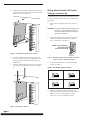
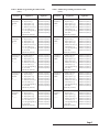
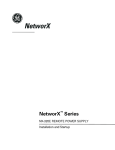
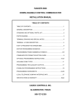
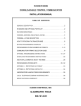
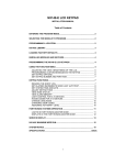
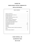
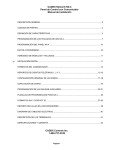
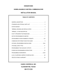
NetworX NX Series
Receiver Modules
NetworX NX Series Receiver Modules
Document Number: 466-1427 Rev. E
August 1998
1)
After mounting the NX-8 cabinet, install the ground
plane screws, washers, and nuts (included) in the holes
on top of the cabinet (see Figure 1).
TOP OF
ENCLOSURE
9740G15A.DS4
60-732
Installation
Instructions
Product Summary
The NX-Series Receiver Modules (8-zone NX-408, 16-zone
NX-416, and 48-zone NX-448) add wireless capabilities to
the Caddx® NetworX NX-8 control panel. Adding a receiver
module makes NX-8 control panels compatible with NX
wireless transmitters and keychain touchpads (keyfobs).
The receiver modules mount inside the NX-8 cabinet and
require just three wire connections for power and data communications to the NX-8 motherboard.
9740G05A.DS4
Figure 1. Installing the Ground Plane Screws, Washers,
and Nuts
2)
Install the circuit board edge guide standoff in the
lower mounting hole, in either of the two spaces
located just to the left of the NX-8 motherboard (see
Figure 2). Do not tighten the standoff at this time.
Installation Guidelines
Use the following guidelines when installing receiver modules:
■
■
■
Leave at least 10" above the control panel for the module’s antennas.
Avoid areas that are likely to expose the module to
moisture.
Avoid areas with excessive metal or electrical wiring,
including furnace and utility rooms.
Installing the Receiver Module
The following steps describe mounting the circuit board
edge guide standoff, securing the module to the cabinet, and
inserting the antennas.
9740G08A.DS4
CAUTION: You must be free of static electricity before
handling circuit boards. Touch a bare metal
surface or wear a grounding strap to discharge yourself.
Figure 2. Installing the Circuit Board Edge Guide
Standoff
Page 1
NetworX NX Series Receiver Modules
3)
Install the module into the cabinet by turning the standoff sideways, then slide the module up onto the ground
plane screw posts (see Figure 3).
Wiring, Module Number DIP Switch
Settings, and Power Up
The following steps describe wiring the module to the NX8, setting the module number DIP switches, and powering
up the NX-8.
1)
Remove power (if applied) from the NX-8 control
panel.
CAUTION: To avoid possible equipment damage or personal injury, remove power from the NX-8
control panel before making any wiring connections to the module.
2)
Connect the module power and data terminals to the
NX-8 power and data terminals using 22-gauge or
larger, stranded wire (see Figure 5).
POWER + (TO NX-8 AUX PWR +)
GND (TO NX-8 COM)
DATA (TO NX-8 KP DATA)
9740G04A.DS4
Figure 3. Installing the Module into the Cabinet
9740G14A.DS4
4)
5)
Turn the standoff so the slot is facing up, insert the
back corner of the module into the standoff slot, then
press up at the front of the standoff and tighten the
standoff screw.
Insert the antennas through the holes on top of the cabinet and into the module antenna sockets (see Figure
4).
Figure 5. Wiring the Module Power and Data Terminals
to the NX-8 Power and Data Terminals
3)
Set the module DIP switches to the desired module
number (see Table 1).
Table 1. NX Module Number Settings
Module Number 32
ON
1 2
EDG
3 4
Module Number 34
ON
1 2
4)
9740G10A.DS4
Figure 4. Inserting the Antennas
Page 2
EDG
3 4
Module Number 33
ON
1 2
EDG
3 4
Module Number 35
ON
1 2
EDG
3 4
If using a NX-408 or NX-416, set DIP switch 3 to
enable zone blocks for transmitter learning as follows:
OFF = zones 9-16 or 9-24 enabled for learning
ON = zones 1-8 or 1-16 enabled for learning
NetworX NX Series Receiver Modules
5)
Apply power to the NX-8. The middle (red) LED on
the module should start blinking. Table 2 describes the
module’s status based on LED conditions.
Table 2. Module Status Conditions
LED
Module Status
Red-blinking
Normal data communication with
NX-8.
Red-off
No data communication with NX-8.
Check wiring and power source.
Green-blinking
Receiving radio signals from Learn
Mode wireless sensors.
Green-off
No radio signals currently being
received.
Note:
The red LED at the bottom of the module may
emit a dim glow but is not used as an indicator
and can be ignored.
Special Settings for Door/Window
Transmitters and Wireless Smoke Detectors
Use the following guidelines when setting features 3 and 4
for door/window transmitters and wireless smoke detectors.
■
Feature 3—Input Option 1
For door/window transmitters, turn on this feature to
disable the transmitter’s internal reed switches.
For wireless smoke detectors with tamper switches,
turn on this feature to enable the tamper feature.
Note:
■
Feature 3—Input Option 1, must be off (disabled)
when using wireless smoke detectors without
tamper switches.
Feature 4—Input Option 2
For door/window transmitters that use a normally open
external contact, leave this feature off (N/O).
For door/window transmitters that use a normally
closed external contact, turn this feature on (N/C).
Programming
This section describes the following programming steps:
■
■
■
Determine Programming Settings—provides tables to
record wireless transmitter and partition settings.
Enroll the Module—sets up the module to be supervised by the NX-8 control panel.
Program the Module—puts the module into program so
you can program transmitters and enter the settings for
transmitters and partitions.
Determine Transmitter Settings
When programming wireless transmitters into the module,
there are various options and partitions you can set for each
transmitter. These settings appear in segments of each programming location.
Check the desired boxes in the programming worksheet
table (Table 3) on pages 4 through 8 to determine the option
and partition settings for each transmitter zone. This gives
you all the programming information in one place and helps
speed up the programming process.
Note:
The default settings shown for Segments 1 and 2
in Location 1 (Zone 1) apply to all zone locations
1 through 48.
Page 3
NetworX NX Series Receiver Modules
Table 3. Module Programming Worksheet Table
(cont.)
Table 3. Module Programming Worksheet Table
Location
Location
Segment 2
0 (Supervision)
1 - Normal ______hrs.
(0 - 255 hours;
default = 24 hours)
Fire ______hrs.
(0 - 255 hours;
default = 4 hours)
1 (Zone 1)
Assigned to
module
#_____.
1 - Enable sensor ❏
(default = off)
2 - Supervised ❏
(default = on)
3 - Input option 1 ❏
(default = off)
4 - Input option 2 ❏
(default = off)
5 - Xmitter not lost* ❏
(default = off)
6 - Low battery* ❏
(default = off)
7 - Last signal good* ❏
(default = off)
8 - Not used*
(*Read only location)
Partition 1 keyfob ❏
(default = on)
Partition 2 keyfob ❏
(default = off)
Partition 3 keyfob ❏
(default = off)
Partition 4 keyfob ❏
(default = off)
Partition 5 keyfob ❏
(default = off)
Partition 6 keyfob ❏
(default = off)
Partition 7 keyfob ❏
(default = off)
Partition 8 keyfob ❏
(default = off)
1 - Enable sensor ❏
2 - Supervised ❏
3 - Input option 1 ❏
4 - Input option 2 ❏
5 - Xmitter not lost* ❏
6 - Low battery* ❏
7 - Last signal good* ❏
8 - Not used*
(*Read only location)
Partition 1 keyfob ❏
Partition 2 keyfob ❏
Partition 3 keyfob ❏
Partition 4 keyfob ❏
Partition 5 keyfob ❏
Partition 6 keyfob ❏
Partition 7 keyfob ❏
Partition 8 keyfob ❏
2 (Zone 2)
Assigned to
module
#_____.
3 (Zone 3)
Assigned to
module
#_____.
4 (Zone 4)
Assigned to
module
#_____.
Page 4
Segment 1
Segment 1
Segment 2
5 (Zone 5)
Assigned to
module
#_____.
1 - Enable sensor ❏
2 - Supervised ❏
3 - Input option 1 ❏
4 - Input option 2 ❏
5 - Xmitter not lost* ❏
6 - Low battery* ❏
7 - Last signal good* ❏
8 - Not used*
(*Read only location)
Partition 1 keyfob ❏
Partition 2 keyfob ❏
Partition 3 keyfob ❏
Partition 4 keyfob ❏
Partition 5 keyfob ❏
Partition 6 keyfob ❏
Partition 7 keyfob ❏
Partition 8 keyfob ❏
6 (Zone 6)
Assigned to
module
#_____.
1 - Enable sensor ❏
2 - Supervised ❏
3 - Input option 1 ❏
4 - Input option 2 ❏
5 - Xmitter not lost* ❏
6 - Low battery* ❏
7 - Last signal good* ❏
8 - Not used*
(*Read only location)
Partition 1 keyfob ❏
Partition 2 keyfob ❏
Partition 3 keyfob ❏
Partition 4 keyfob ❏
Partition 5 keyfob ❏
Partition 6 keyfob ❏
Partition 7 keyfob ❏
Partition 8 keyfob ❏
7 (Zone 7)
Assigned to
module
#_____.
1 - Enable sensor ❏
2 - Supervised ❏
3 - Input option 1 ❏
4 - Input option 2 ❏
5 - Xmitter not lost* ❏
6 - Low battery* ❏
7 - Last signal good* ❏
8 - Not used*
(*Read only location)
Partition 1 keyfob ❏
Partition 2 keyfob ❏
Partition 3 keyfob ❏
Partition 4 keyfob ❏
Partition 5 keyfob ❏
Partition 6 keyfob ❏
Partition 7 keyfob ❏
Partition 8 keyfob ❏
8 (Zone 8)
Assigned to
module
#_____.
1 - Enable sensor ❏
2 - Supervised ❏
3 - Input option 1 ❏
4 - Input option 2 ❏
5 - Xmitter not lost* ❏
6 - Low battery* ❏
7 - Last signal good* ❏
8 - Not used*
(*Read only location)
Partition 1 keyfob ❏
Partition 2 keyfob ❏
Partition 3 keyfob ❏
Partition 4 keyfob ❏
Partition 5 keyfob ❏
Partition 6 keyfob ❏
Partition 7 keyfob ❏
Partition 8 keyfob ❏
9 (Zone 9)
Assigned to
module
#_____.
1 - Enable sensor ❏
2 - Supervised ❏
3 - Input option 1 ❏
4 - Input option 2 ❏
5 - Xmitter not lost* ❏
6 - Low battery* ❏
7 - Last signal good* ❏
8 - Not used*
(*Read only location)
Partition 1 keyfob ❏
Partition 2 keyfob ❏
Partition 3 keyfob ❏
Partition 4 keyfob ❏
Partition 5 keyfob ❏
Partition 6 keyfob ❏
Partition 7 keyfob ❏
Partition 8 keyfob ❏
NetworX NX Series Receiver Modules
Table 3. Module Programming Worksheet Table
(cont.)
Table 3. Module Programming Worksheet Table
(cont.)
Location
Segment 1
Segment 2
Location
Segment 1
Segment 2
10 (Zone 10)
Assigned to
module
#_____.
1 - Enable sensor ❏
2 - Supervised ❏
3 - Input option 1 ❏
4 - Input option 2 ❏
5 - Xmitter not lost* ❏
6 - Low battery* ❏
7 - Last signal good* ❏
8 - Not used*
(*Read only location)
Partition 1 keyfob ❏
Partition 2 keyfob ❏
Partition 3 keyfob ❏
Partition 4 keyfob ❏
Partition 5 keyfob ❏
Partition 6 keyfob ❏
Partition 7 keyfob ❏
Partition 8 keyfob ❏
15 (Zone 15)
Assigned to
module
#_____.
1 - Enable sensor ❏
2 - Supervised ❏
3 - Input option 1 ❏
4 - Input option 2 ❏
5 - Xmitter not lost* ❏
6 - Low battery* ❏
7 - Last signal good* ❏
8 - Not used*
(*Read only location)
Partition 1 keyfob ❏
Partition 2 keyfob ❏
Partition 3 keyfob ❏
Partition 4 keyfob ❏
Partition 5 keyfob ❏
Partition 6 keyfob ❏
Partition 7 keyfob ❏
Partition 8 keyfob ❏
11 (Zone 11)
Assigned to
module
#_____.
1 - Enable sensor ❏
2 - Supervised ❏
3 - Input option 1 ❏
4 - Input option 2 ❏
5 - Xmitter not lost* ❏
6 - Low battery* ❏
7 - Last signal good* ❏
8 - Not used*
(*Read only location)
Partition 1 keyfob ❏
Partition 2 keyfob ❏
Partition 3 keyfob ❏
Partition 4 keyfob ❏
Partition 5 keyfob ❏
Partition 6 keyfob ❏
Partition 7 keyfob ❏
Partition 8 keyfob ❏
16 (Zone 16)
Assigned to
module
#_____.
1 - Enable sensor ❏
2 - Supervised ❏
3 - Input option 1 ❏
4 - Input option 2 ❏
5 - Xmitter not lost* ❏
6 - Low battery* ❏
7 - Last signal good* ❏
8 - Not used*
(*Read only location)
Partition 1 keyfob ❏
Partition 2 keyfob ❏
Partition 3 keyfob ❏
Partition 4 keyfob ❏
Partition 5 keyfob ❏
Partition 6 keyfob ❏
Partition 7 keyfob ❏
Partition 8 keyfob ❏
12 (Zone 12)
Assigned to
module
#_____.
1 - Enable sensor ❏
2 - Supervised ❏
3 - Input option 1 ❏
4 - Input option 2 ❏
5 - Xmitter not lost* ❏
6 - Low battery* ❏
7 - Last signal good* ❏
8 - Not used*
(*Read only location)
Partition 1 keyfob ❏
Partition 2 keyfob ❏
Partition 3 keyfob ❏
Partition 4 keyfob ❏
Partition 5 keyfob ❏
Partition 6 keyfob ❏
Partition 7 keyfob ❏
Partition 8 keyfob ❏
17 (Zone 17)
Assigned to
module
#_____.
1 - Enable sensor ❏
2 - Supervised ❏
3 - Input option 1 ❏
4 - Input option 2 ❏
5 - Xmitter not lost* ❏
6 - Low battery* ❏
7 - Last signal good* ❏
8 - Not used*
(*Read only location)
Partition 1 keyfob ❏
Partition 2 keyfob ❏
Partition 3 keyfob ❏
Partition 4 keyfob ❏
Partition 5 keyfob ❏
Partition 6 keyfob ❏
Partition 7 keyfob ❏
Partition 8 keyfob ❏
13 (Zone 13)
Assigned to
module
#_____.
1 - Enable sensor ❏
2 - Supervised ❏
3 - Input option 1 ❏
4 - Input option 2 ❏
5 - Xmitter not lost* ❏
6 - Low battery* ❏
7 - Last signal good* ❏
8 - Not used*
(*Read only location)
Partition 1 keyfob ❏
Partition 2 keyfob ❏
Partition 3 keyfob ❏
Partition 4 keyfob ❏
Partition 5 keyfob ❏
Partition 6 keyfob ❏
Partition 7 keyfob ❏
Partition 8 keyfob ❏
18 (Zone 18)
Assigned to
module
#_____.
1 - Enable sensor ❏
2 - Supervised ❏
3 - Input option 1 ❏
4 - Input option 2 ❏
5 - Xmitter not lost* ❏
6 - Low battery* ❏
7 - Last signal good* ❏
8 - Not used*
(*Read only location)
Partition 1 keyfob ❏
Partition 2 keyfob ❏
Partition 3 keyfob ❏
Partition 4 keyfob ❏
Partition 5 keyfob ❏
Partition 6 keyfob ❏
Partition 7 keyfob ❏
Partition 8 keyfob ❏
14 (Zone 14)
Assigned to
module
#_____.
1 - Enable sensor ❏
2 - Supervised ❏
3 - Input option 1 ❏
4 - Input option 2 ❏
5 - Xmitter not lost* ❏
6 - Low battery* ❏
7 - Last signal good* ❏
8 - Not used*
(*Read only location)
Partition 1 keyfob ❏
Partition 2 keyfob ❏
Partition 3 keyfob ❏
Partition 4 keyfob ❏
Partition 5 keyfob ❏
Partition 6 keyfob ❏
Partition 7 keyfob ❏
Partition 8 keyfob ❏
19 (Zone 19)
Assigned to
module
#_____.
1 - Enable sensor ❏
2 - Supervised ❏
3 - Input option 1 ❏
4 - Input option 2 ❏
5 - Xmitter not lost* ❏
6 - Low battery* ❏
7 - Last signal good* ❏
8 - Not used*
(*Read only location)
Partition 1 keyfob ❏
Partition 2 keyfob ❏
Partition 3 keyfob ❏
Partition 4 keyfob ❏
Partition 5 keyfob ❏
Partition 6 keyfob ❏
Partition 7 keyfob ❏
Partition 8 keyfob ❏
Page 5
NetworX NX Series Receiver Modules
Table 3. Module Programming Worksheet Table
(cont.)
Page 6
Table 3. Module Programming Worksheet Table
(cont.)
Location
Segment 1
Segment 2
Location
Segment 1
Segment 2
20 (Zone 20)
Assigned to
module
#_____.
1 - Enable sensor ❏
2 - Supervised ❏
3 - Input option 1 ❏
4 - Input option 2 ❏
5 - Xmitter not lost* ❏
6 - Low battery* ❏
7 - Last signal good* ❏
8 - Not used*
(*Read only location)
Partition 1 keyfob ❏
Partition 2 keyfob ❏
Partition 3 keyfob ❏
Partition 4 keyfob ❏
Partition 5 keyfob ❏
Partition 6 keyfob ❏
Partition 7 keyfob ❏
Partition 8 keyfob ❏
25 (Zone 25)
Assigned to
module
#_____.
1 - Enable sensor ❏
2 - Supervised ❏
3 - Input option 1 ❏
4 - Input option 2 ❏
5 - Xmitter not lost* ❏
6 - Low battery* ❏
7 - Last signal good* ❏
8 - Not used*
(*Read only location)
Partition 1 keyfob ❏
Partition 2 keyfob ❏
Partition 3 keyfob ❏
Partition 4 keyfob ❏
Partition 5 keyfob ❏
Partition 6 keyfob ❏
Partition 7 keyfob ❏
Partition 8 keyfob ❏
21 (Zone 21)
Assigned to
module
#_____.
1 - Enable sensor ❏
2 - Supervised ❏
3 - Input option 1 ❏
4 - Input option 2 ❏
5 - Xmitter not lost* ❏
6 - Low battery* ❏
7 - Last signal good* ❏
8 - Not used*
(*Read only location)
Partition 1 keyfob ❏
Partition 2 keyfob ❏
Partition 3 keyfob ❏
Partition 4 keyfob ❏
Partition 5 keyfob ❏
Partition 6 keyfob ❏
Partition 7 keyfob ❏
Partition 8 keyfob ❏
26 (Zone 26)
Assigned to
module
#_____.
1 - Enable sensor ❏
2 - Supervised ❏
3 - Input option 1 ❏
4 - Input option 2 ❏
5 - Xmitter not lost* ❏
6 - Low battery* ❏
7 - Last signal good* ❏
8 - Not used*
(*Read only location)
Partition 1 keyfob ❏
Partition 2 keyfob ❏
Partition 3 keyfob ❏
Partition 4 keyfob ❏
Partition 5 keyfob ❏
Partition 6 keyfob ❏
Partition 7 keyfob ❏
Partition 8 keyfob ❏
22 (Zone 22)
Assigned to
module
#_____.
1 - Enable sensor ❏
2 - Supervised ❏
3 - Input option 1 ❏
4 - Input option 2 ❏
5 - Xmitter not lost* ❏
6 - Low battery* ❏
7 - Last signal good* ❏
8 - Not used*
(*Read only location)
Partition 1 keyfob ❏
Partition 2 keyfob ❏
Partition 3 keyfob ❏
Partition 4 keyfob ❏
Partition 5 keyfob ❏
Partition 6 keyfob ❏
Partition 7 keyfob ❏
Partition 8 keyfob ❏
27 (Zone 27)
Assigned to
module
#_____.
1 - Enable sensor ❏
2 - Supervised ❏
3 - Input option 1 ❏
4 - Input option 2 ❏
5 - Xmitter not lost* ❏
6 - Low battery* ❏
7 - Last signal good* ❏
8 - Not used*
(*Read only location)
Partition 1 keyfob ❏
Partition 2 keyfob ❏
Partition 3 keyfob ❏
Partition 4 keyfob ❏
Partition 5 keyfob ❏
Partition 6 keyfob ❏
Partition 7 keyfob ❏
Partition 8 keyfob ❏
23 (Zone 23)
Assigned to
module
#_____.
1 - Enable sensor ❏
2 - Supervised ❏
3 - Input option 1 ❏
4 - Input option 2 ❏
5 - Xmitter not lost* ❏
6 - Low battery* ❏
7 - Last signal good* ❏
8 - Not used*
(*Read only location)
Partition 1 keyfob ❏
Partition 2 keyfob ❏
Partition 3 keyfob ❏
Partition 4 keyfob ❏
Partition 5 keyfob ❏
Partition 6 keyfob ❏
Partition 7 keyfob ❏
Partition 8 keyfob ❏
28 (Zone 28)
Assigned to
module
#_____.
1 - Enable sensor ❏
2 - Supervised ❏
3 - Input option 1 ❏
4 - Input option 2 ❏
5 - Xmitter not lost* ❏
6 - Low battery* ❏
7 - Last signal good* ❏
8 - Not used*
(*Read only location)
Partition 1 keyfob ❏
Partition 2 keyfob ❏
Partition 3 keyfob ❏
Partition 4 keyfob ❏
Partition 5 keyfob ❏
Partition 6 keyfob ❏
Partition 7 keyfob ❏
Partition 8 keyfob ❏
24 (Zone 24)
Assigned to
module
#_____.
1 - Enable sensor ❏
2 - Supervised ❏
3 - Input option 1 ❏
4 - Input option 2 ❏
5 - Xmitter not lost* ❏
6 - Low battery* ❏
7 - Last signal good* ❏
8 - Not used*
(*Read only location)
Partition 1 keyfob ❏
Partition 2 keyfob ❏
Partition 3 keyfob ❏
Partition 4 keyfob ❏
Partition 5 keyfob ❏
Partition 6 keyfob ❏
Partition 7 keyfob ❏
Partition 8 keyfob ❏
29 (Zone 29)
Assigned to
module
#_____.
1 - Enable sensor ❏
2 - Supervised ❏
3 - Input option 1 ❏
4 - Input option 2 ❏
5 - Xmitter not lost* ❏
6 - Low battery* ❏
7 - Last signal good* ❏
8 - Not used*
(*Read only location)
Partition 1 keyfob ❏
Partition 2 keyfob ❏
Partition 3 keyfob ❏
Partition 4 keyfob ❏
Partition 5 keyfob ❏
Partition 6 keyfob ❏
Partition 7 keyfob ❏
Partition 8 keyfob ❏
NetworX NX Series Receiver Modules
Table 3. Module Programming Worksheet Table
(cont.)
Table 3. Module Programming Worksheet Table
(cont.)
Location
Segment 1
Segment 2
Location
Segment 1
Segment 2
30 (Zone 30)
Assigned to
module
#_____.
1 - Enable sensor ❏
2 - Supervised ❏
3 - Input option 1 ❏
4 - Input option 2 ❏
5 - Xmitter not lost* ❏
6 - Low battery* ❏
7 - Last signal good* ❏
8 - Not used*
(*Read only location)
Partition 1 keyfob ❏
Partition 2 keyfob ❏
Partition 3 keyfob ❏
Partition 4 keyfob ❏
Partition 5 keyfob ❏
Partition 6 keyfob ❏
Partition 7 keyfob ❏
Partition 8 keyfob ❏
35 (Zone 35)
Assigned to
module
#_____.
1 - Enable sensor ❏
2 - Supervised ❏
3 - Input option 1 ❏
4 - Input option 2 ❏
5 - Xmitter not lost* ❏
6 - Low battery* ❏
7 - Last signal good* ❏
8 - Not used*
(*Read only location)
Partition 1 keyfob ❏
Partition 2 keyfob ❏
Partition 3 keyfob ❏
Partition 4 keyfob ❏
Partition 5 keyfob ❏
Partition 6 keyfob ❏
Partition 7 keyfob ❏
Partition 8 keyfob ❏
31 (Zone 31)
Assigned to
module
#_____.
1 - Enable sensor ❏
2 - Supervised ❏
3 - Input option 1 ❏
4 - Input option 2 ❏
5 - Xmitter not lost* ❏
6 - Low battery* ❏
7 - Last signal good* ❏
8 - Not used*
(*Read only location)
Partition 1 keyfob ❏
Partition 2 keyfob ❏
Partition 3 keyfob ❏
Partition 4 keyfob ❏
Partition 5 keyfob ❏
Partition 6 keyfob ❏
Partition 7 keyfob ❏
Partition 8 keyfob ❏
36 (Zone 36)
Assigned to
module
#_____.
1 - Enable sensor ❏
2 - Supervised ❏
3 - Input option 1 ❏
4 - Input option 2 ❏
5 - Xmitter not lost* ❏
6 - Low battery* ❏
7 - Last signal good* ❏
8 - Not used*
(*Read only location)
Partition 1 keyfob ❏
Partition 2 keyfob ❏
Partition 3 keyfob ❏
Partition 4 keyfob ❏
Partition 5 keyfob ❏
Partition 6 keyfob ❏
Partition 7 keyfob ❏
Partition 8 keyfob ❏
32 (Zone 32)
Assigned to
module
#_____.
1 - Enable sensor ❏
2 - Supervised ❏
3 - Input option 1 ❏
4 - Input option 2 ❏
5 - Xmitter not lost* ❏
6 - Low battery* ❏
7 - Last signal good* ❏
8 - Not used*
(*Read only location)
Partition 1 keyfob ❏
Partition 2 keyfob ❏
Partition 3 keyfob ❏
Partition 4 keyfob ❏
Partition 5 keyfob ❏
Partition 6 keyfob ❏
Partition 7 keyfob ❏
Partition 8 keyfob ❏
37 (Zone 37)
Assigned to
module
#_____.
1 - Enable sensor ❏
2 - Supervised ❏
3 - Input option 1 ❏
4 - Input option 2 ❏
5 - Xmitter not lost* ❏
6 - Low battery* ❏
7 - Last signal good* ❏
8 - Not used*
(*Read only location)
Partition 1 keyfob ❏
Partition 2 keyfob ❏
Partition 3 keyfob ❏
Partition 4 keyfob ❏
Partition 5 keyfob ❏
Partition 6 keyfob ❏
Partition 7 keyfob ❏
Partition 8 keyfob ❏
33 (Zone 33)
Assigned to
module
#_____.
1 - Enable sensor ❏
2 - Supervised ❏
3 - Input option 1 ❏
4 - Input option 2 ❏
5 - Xmitter not lost* ❏
6 - Low battery* ❏
7 - Last signal good* ❏
8 - Not used*
(*Read only location)
Partition 1 keyfob ❏
Partition 2 keyfob ❏
Partition 3 keyfob ❏
Partition 4 keyfob ❏
Partition 5 keyfob ❏
Partition 6 keyfob ❏
Partition 7 keyfob ❏
Partition 8 keyfob ❏
38 (Zone 38)
Assigned to
module
#_____.
1 - Enable sensor ❏
2 - Supervised ❏
3 - Input option 1 ❏
4 - Input option 2 ❏
5 - Xmitter not lost* ❏
6 - Low battery* ❏
7 - Last signal good* ❏
8 - Not used*
(*Read only location)
Partition 1 keyfob ❏
Partition 2 keyfob ❏
Partition 3 keyfob ❏
Partition 4 keyfob ❏
Partition 5 keyfob ❏
Partition 6 keyfob ❏
Partition 7 keyfob ❏
Partition 8 keyfob ❏
34 (Zone 34)
Assigned to
module
#_____.
1 - Enable sensor ❏
2 - Supervised ❏
3 - Input option 1 ❏
4 - Input option 2 ❏
5 - Xmitter not lost* ❏
6 - Low battery* ❏
7 - Last signal good* ❏
8 - Not used*
(*Read only location)
Partition 1 keyfob ❏
Partition 2 keyfob ❏
Partition 3 keyfob ❏
Partition 4 keyfob ❏
Partition 5 keyfob ❏
Partition 6 keyfob ❏
Partition 7 keyfob ❏
Partition 8 keyfob ❏
39 (Zone 39)
Assigned to
module
#_____.
1 - Enable sensor ❏
2 - Supervised ❏
3 - Input option 1 ❏
4 - Input option 2 ❏
5 - Xmitter not lost* ❏
6 - Low battery* ❏
7 - Last signal good* ❏
8 - Not used*
(*Read only location)
Partition 1 keyfob ❏
Partition 2 keyfob ❏
Partition 3 keyfob ❏
Partition 4 keyfob ❏
Partition 5 keyfob ❏
Partition 6 keyfob ❏
Partition 7 keyfob ❏
Partition 8 keyfob ❏
Page 7
NetworX NX Series Receiver Modules
Table 3. Module Programming Worksheet Table
(cont.)
Page 8
Table 3. Module Programming Worksheet Table
(cont.)
Location
Segment 1
Segment 2
Location
Segment 1
Segment 2
40 (Zone 40)
Assigned to
module
#_____.
1 - Enable sensor ❏
2 - Supervised ❏
3 - Input option 1 ❏
4 - Input option 2 ❏
5 - Xmitter not lost* ❏
6 - Low battery* ❏
7 - Last signal good* ❏
8 - Not used*
(*Read only location)
Partition 1 keyfob ❏
Partition 2 keyfob ❏
Partition 3 keyfob ❏
Partition 4 keyfob ❏
Partition 5 keyfob ❏
Partition 6 keyfob ❏
Partition 7 keyfob ❏
Partition 8 keyfob ❏
45 (Zone 45)
Assigned to
module
#_____.
1 - Enable sensor ❏
2 - Supervised ❏
3 - Input option 1 ❏
4 - Input option 2 ❏
5 - Xmitter not lost* ❏
6 - Low battery* ❏
7 - Last signal good* ❏
8 - Not used*
(*Read only location)
Partition 1 keyfob ❏
Partition 2 keyfob ❏
Partition 3 keyfob ❏
Partition 4 keyfob ❏
Partition 5 keyfob ❏
Partition 6 keyfob ❏
Partition 7 keyfob ❏
Partition 8 keyfob ❏
41 (Zone 41)
Assigned to
module
#_____.
1 - Enable sensor ❏
2 - Supervised ❏
3 - Input option 1 ❏
4 - Input option 2 ❏
5 - Xmitter not lost* ❏
6 - Low battery* ❏
7 - Last signal good* ❏
8 - Not used*
(*Read only location)
Partition 1 keyfob ❏
Partition 2 keyfob ❏
Partition 3 keyfob ❏
Partition 4 keyfob ❏
Partition 5 keyfob ❏
Partition 6 keyfob ❏
Partition 7 keyfob ❏
Partition 8 keyfob ❏
46 (Zone 46)
Assigned to
module
#_____.
1 - Enable sensor ❏
2 - Supervised ❏
3 - Input option 1 ❏
4 - Input option 2 ❏
5 - Xmitter not lost* ❏
6 - Low battery* ❏
7 - Last signal good* ❏
8 - Not used*
(*Read only location)
Partition 1 keyfob ❏
Partition 2 keyfob ❏
Partition 3 keyfob ❏
Partition 4 keyfob ❏
Partition 5 keyfob ❏
Partition 6 keyfob ❏
Partition 7 keyfob ❏
Partition 8 keyfob ❏
42 (Zone 42)
Assigned to
module
#_____.
1 - Enable sensor ❏
2 - Supervised ❏
3 - Input option 1 ❏
4 - Input option 2 ❏
5 - Xmitter not lost* ❏
6 - Low battery* ❏
7 - Last signal good* ❏
8 - Not used*
(*Read only location)
Partition 1 keyfob ❏
Partition 2 keyfob ❏
Partition 3 keyfob ❏
Partition 4 keyfob ❏
Partition 5 keyfob ❏
Partition 6 keyfob ❏
Partition 7 keyfob ❏
Partition 8 keyfob ❏
47 (Zone 47)
Assigned to
module
#_____.
1 - Enable sensor ❏
2 - Supervised ❏
3 - Input option 1 ❏
4 - Input option 2 ❏
5 - Xmitter not lost* ❏
6 - Low battery* ❏
7 - Last signal good* ❏
8 - Not used*
(*Read only location)
Partition 1 keyfob ❏
Partition 2 keyfob ❏
Partition 3 keyfob ❏
Partition 4 keyfob ❏
Partition 5 keyfob ❏
Partition 6 keyfob ❏
Partition 7 keyfob ❏
Partition 8 keyfob ❏
43 (Zone 43)
Assigned to
module
#_____.
1 - Enable sensor ❏
2 - Supervised ❏
3 - Input option 1 ❏
4 - Input option 2 ❏
5 - Xmitter not lost* ❏
6 - Low battery* ❏
7 - Last signal good* ❏
8 - Not used*
(*Read only location)
Partition 1 keyfob ❏
Partition 2 keyfob ❏
Partition 3 keyfob ❏
Partition 4 keyfob ❏
Partition 5 keyfob ❏
Partition 6 keyfob ❏
Partition 7 keyfob ❏
Partition 8 keyfob ❏
48 (Zone 48)
Assigned to
module
#_____.
1 - Enable sensor ❏
2 - Supervised ❏
3 - Input option 1 ❏
4 - Input option 2 ❏
5 - Xmitter not lost* ❏
6 - Low battery* ❏
7 - Last signal good* ❏
8 - Not used*
(*Read only location)
Partition 1 keyfob ❏
Partition 2 keyfob ❏
Partition 3 keyfob ❏
Partition 4 keyfob ❏
Partition 5 keyfob ❏
Partition 6 keyfob ❏
Partition 7 keyfob ❏
Partition 8 keyfob ❏
44 (Zone 44)
Assigned to
module
#_____.
1 - Enable sensor ❏
2 - Supervised ❏
3 - Input option 1 ❏
4 - Input option 2 ❏
5 - Xmitter not lost* ❏
6 - Low battery* ❏
7 - Last signal good* ❏
8 - Not used*
(*Read only location)
Partition 1 keyfob ❏
Partition 2 keyfob ❏
Partition 3 keyfob ❏
Partition 4 keyfob ❏
Partition 5 keyfob ❏
Partition 6 keyfob ❏
Partition 7 keyfob ❏
Partition 8 keyfob ❏
49 (Transmitter to be
programmed)
None
None
NetworX NX Series Receiver Modules
trol panel is enrolling the module. After about 12 seconds, the service LED should turn off.
Table 3. Module Programming Worksheet Table
(cont.)
Location
50 (All
default off)
51 (Default
= 0)
Segment 1
Segment 2
1 - Keyfob user ID ❏
(off = all keyfobs
report as user 99;
on = keyfob reports
as its learned zone)
2 - Enable jam detect ❏
3 - Enable antenna
tamper (Only
selectable on International versions,
reports as box
tamper) ❏
4 - Enable auto
advance to next
zone number ❏
5 - Enable partition 1
audible programming beeps ❏
6-8 Not used
Starting zone number
for receiver
0 = 1* (default) ❏
1=9❏
2 = 17 ❏
3 = 25 ❏
4 = 33 ❏
5 = 41 ❏
(* When set to 0, the
starting zone number
is determined by DIP
switch 3 setting.)
Enroll the Module
The following steps describe how to enroll and program the
module to be supervised by the NX-8.
1)
2)
3)
4)
5)
With power applied and the system disarmed, enter [✻]
[8] at the keypad. The five function lights should start
flashing.
Enter the “Go To Program Code” (factory default is 9 7
1 3). The service light should flash and the five function lights should change from flashing to on steady.
Enter [0] [#], where [0] is the NX-8 control panel number and [#] is the entry key. The Armed LED should
turn on, indicating the control panel is waiting for a
programming location entry.
Enter [9] [1] [5] [#] to enroll the module for supervision. The keypad sounder should beep three times indicating the NX-8 has accepted the enrolling request.
Exit program mode by entering [EXIT] [EXIT]. The
Service LED on the NX-8 turns on, indicating the con-
Program the Module
The following steps describe how to get the module into
program mode, load factory defaults if installing a new system, and program transmitters into memory.
Programming Guidelines
■
■
■
When a transmitter is learned into memory, the module
claims a block of eight zones around that number (1-8,
9-16, 17-24, etc.). For example, learning a transmitter
into zone 13 automatically claims the zone block of 9
through 16. Only wireless transmitters can now be
assigned to these zones.
Do not learn wireless transmitters into a zone block
claimed by a hardwire expander or the panel.
If two modules are installed, they cannot share the
same zone block. For example, wireless transmitters
learned into zones 11 and 12 must reside in one module.
Fill in Table 4 to help keep track of zone block module
assignments. Be sure to circle the module type; RM =
receiver module, HE = hardwire expander, P = panel.
Table 4. Zone Block Module Assignments
Zone Block
Assigned To Module
1-8
RM HE P #______
9 - 16
RM HE P #______
17 - 24
RM HE P #______
25 - 32
RM HE P #______
33 - 40
RM HE P #______
41 - 48
RM HE P #______
To program the module:
1)
2)
3)
4)
Enter [✻] [8] at the keypad. The five function lights
should start flashing.
Enter the “Go To Program Code” (factory default is 9 7
1 3). The service light should flash and the five function lights should change from flashing to on steady.
Enter [XX] [#], where [XX] is the DIP switch setting
module number and [#] is the entry key. The Armed
LED should turn on, indicating the control panel is
waiting for a programming location entry.
For new installations, enter [9] [1] [0] [#] to load factory defaults and clear any unwanted information in
memory before any further programming.
Page 9
NetworX NX Series Receiver Modules
5)
6)
Enter [4] [9] [#] to enter the sensor learning location.
The Ready LED should turn on and the Armed LED
should turn off.
Enter [XX] [✻], where [XX] is a zone number (1
through 48) and [✻] is the entry key.
Note:
Three beeps from the keypad indicates an entry
error. This occurs if you enter a transmitter number that is not within the module’s zone block or if
you try learning a sensor that is already learned
into the module.
If you change your mind about your entry, you
can terminate programming by entering [4] [9] [#]
[0] [✻]. Then, start again from step 5.
7)
Trip the desired transmitter (within 250 seconds) as
described in Table 5. Listen for the ‘ding dong’ for
confirmation.
Table 5. Tripping Transmitters for Learning
Transmitter
Action
Door/Window, Shock,
Glass Guard, Freeze
Activate tamper switch by
removing cover.
Door/Window with External Contact
Activate tamper switch by
removing cover. (Note:
Feature 3—Input Option
1, must be on.)
Recessed Door/Window
Activate tamper switch by
removing circuit board
until tamper switch is
exposed.
Micro Door/Window
Slide the battery about
half-way out of the battery
holder, then back.
PIR
Activate tamper switch by
removing back plate from
PIR.
Smoke Detector
Press and hold the test button.
Heat Detector
Press, then release the
tamper switch.
Fire Pull
Activate tamper switch by
removing sensor cover.
Single Button Panic
Press and hold the button.
Dual Button Panic
Press and hold both buttons together.
Table 5. Tripping Transmitters for Learning
Transmitter
Keyfobs
Press and hold the arm and
disarm buttons together.
Repeater
Press, then release the
tamper switch.
8)
9)
Program remaining transmitters by repeating steps 5-7.
Exit program mode by entering [EXIT] [EXIT].
Program Transmitter and Partition
Settings
This section describes programming guidelines, how to
change the supervision windows, and program the transmitter and partition settings using the information you entered
in the Table 3 programming worksheets.
Changing the Transmitter Supervision
Windows
Note:
For UL Listed installations, the normal supervision window must be set to 24 hours and the fire
supervision window must be set to 4 hours.
CAUTION: Do not set the normal or fire supervision windows to 1 hour. This causes false trouble
reports from all learned wireless transmitters.
1)
2)
3)
4)
5)
Enter [✻] [8] at the keypad. The five function lights
should start flashing.
Enter the “Go To Program Code” (factory default is 9 7
1 3). The service light should flash and the five function lights should change from flashing to on steady.
Enter [XX] [#], where [XX] is the DIP switch setting
module number and [#] is the entry key. The Armed
LED should turn on, indicating the control panel is
waiting for a programming location entry.
Enter [0] [#] to enter location 0, segment 1.
Enter the new normal supervision time (0 - 255).
Note:
6)
7)
Choosing 0 sets the normal supervision window
to 256 hours.
Press [✻] to save any changes and automatically enter
segment 2.
Enter the new fire supervision time (0 - 255).
Note:
Page 10
Action
Choosing 0 sets the fire supervision window to
256 hours.
NetworX NX Series Receiver Modules
8)
Press [✻] to save any changes. The panel is now waiting for the next location entry.
Note:
9)
Pressing [#] does not save changes to the current segment, but does save changes made in
previous segments.
Enter [EXIT] [EXIT] when all changes are completed.
Programming Transmitter and Partition
Settings
1)
Enter [✻] [8] at the keypad. The five function lights
should start flashing.
2) Enter the “Go To Program Code” (factory default is 9 7
1 3). The service light should flash and the five function lights should change from flashing to on steady.
3) Enter [XX] [#], where [XX] is the DIP switch setting
module number and [#] is the entry key. The Armed
LED should turn on, indicating the control panel is
waiting for a programming location entry.
4) Enter [XX] [#] to enter a location. For example, enter
[1] [#] to enter location 1, segment 1. The Armed LED
should turn on and the zone LEDs display the binary
data for the current settings.
or-- Enter [1] [#] [✻] to enter location 1, segment 2.
5) Enter [X] [✻], where [X] is the setting number (1 - 8)
from Table 5 that corresponds to the desired feature or
partition setting number and [✻] is the entry key. The
keypad displays the settings for that location and segment.
6) Press the keypad button that corresponds to the feature
number you want changed. Lights corresponding to the
feature number turn on or off each time the button is
pressed. Lights that turn on indicate the feature is on,
lights that turn off indicate the feature is off.
For example, turn on transmitter features 1 (Transmitter Enabled) and 3 (Input Option 1) by pressing [1] [3].
The 1 and 3 LEDs turn on to indicate the features are
turned on and the Ready LED flashes to indicate the
change request.
7) Press [✻] to enter the changes and automatically
advance to segment 2.
Note:
8)
Pressing [#] does not save changes to the current segment, but does save changes made in
previous segments. Repeat steps 4 - 7 to reenter and make changes to a location and segment.
Press the keypad button that corresponds to the partition number you want changed. Lights corresponding
to the partition number turn on or off each time the button is pressed. Lights that turn on indicate the keyfob is
active in that partition, lights that turn off indicate the
keyfob is inactive.
9)
Repeat steps 4 - 8 to continue programming transmitter
partition settings.
10) Enter [EXIT] [EXIT] when finished.
Deleting Transmitters
The following steps describe how to delete transmitters from
the module.
This procedure makes the module ignore a transmitter but
does not remove transmitter identification from the module’s memory. The transmitter can be reactivated later or a
new one can be learned into the zone.
1)
Enter [✻] [8] at the keypad. The five function lights
should start flashing.
2) Enter the “Go To Program Code” (factory default is 9 7
1 3). The service light should flash and the five function lights should change from flashing to on steady.
3) Enter [XX] [#], where [XX] is the DIP switch setting
module number and [#] is the entry key. The Armed
LED should turn on, indicating the control panel is
waiting for a programming location entry.
4) Enter [XX] [#] to enter the zone location to be deleted.
The Armed LED should turn on and the zone LEDs
display the binary data for the current settings.
5) Change transmitter feature 1 (Transmitter Enabled) by
pressing [1]. The 1 LED turns off to indicate the feature
change and the Ready LED flashes to indicate the
change request.
6) Enter [✻] [#]. The Ready LED stops flashing, indicating the new settings are stored in memory and the system automatically exits from that location.
7) Continue deleting transmitters by entering the desired
locations and segments in steps 4 through 6.
or-- Enter [9] [1] [0] [#] to delete all transmitters and load
factory defaults.
8) Enter [EXIT] [EXIT] when finished.
Testing Wireless Transmitters
Test all transmitters to verify correct programming and
operation, using the steps below.
1)
2)
3)
4)
Trip a transmitter (open a door, walk in front of a PIR,
etc.).
Enter [✻] [8] at the keypad. The five function lights
should start flashing.
Enter the “Go To Program Code” (factory default is 9 7
1 3). The service light should flash and the five function lights should change from flashing to on steady.
Enter [XX] [#], where [XX] is the DIP switch setting
module number and [#] is the entry key. The Armed
LED should turn on, indicating the control panel is
waiting for a programming location entry.
Page 11
NetworX NX Series Receiver Modules
5)
6)
Enter the tripped transmitters’ location.
Observe keypad light 7 which should be on, indicating
the transmitters’ signal is good.
If keypad light 7 is off (transmitter test below margin),
exit program mode and repeat steps 1-6 above.
Troubleshooting
Any transmitters that consistently test below margin should
be rotated in mounting position (90°, 180°, or 270°) and
retested.
If rotating the transmitter mounting position does not
improve signal reception or is not practical, move the transmitter to different locations near the desired mounting area.
Test each location until the transmitter consistently tests
good, then mount the transmitter.
Specifications
Compatibility: NX-8 control panel
Frequency: 319.5 MHz (NX-408, NX-416, & NX-448)
433 MHz (NX-408-I, NX-416-I, & NX-448-I)
Required Power: 12.0 VDC (provided by panel)
Current Draw: 20 mA maximum
Operating Temperature Range: 32° to 120°F
Dimensions: 4.65" x 3.20" (L x W)
U.L. Listings
The NetworX NX Series Receiver Modules (60-732) are
U.L. Listed for UL1023 Household Burglary, UL985
Household Fire, and are listed for use with the following
U.L. Listed devices:
NX-451 Door/Window Sensor (60-670-95R)
NX-470 4-Button Keychain Touchpad (60-659-95R)
NX-475 Water-Resistant Pendant Panic Button (60-578)
NX-480 PIR Motion Sensor (60-639-95R)
NX-490 Wireless Smoke Sensor (60-506)
Notices
This device complies with FCC Rules Part 15. Operation is subject to the following two conditions:
1) This device may not cause harmful interference.
2) This device must accept any interference that may be received, including
interference that may cause undesired operation.
Changes or modifications not expressly approved by Interactive Technologies, Inc. can void the user’s authority to operate the equipment.
Caddx Controls, Inc. 1420 North Main Street Gladewater, Texas 75647
Toll Free: 1-800-727-2339 FAX: (903) 845-6811
Caddx is a registered trademark of Caddx Controls, Inc.
Page 12