1
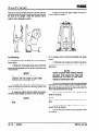
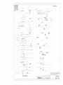
SM-619
G127,GP127
Gl27E, GPl27E
CUIRK
CONTENTS
SERVICE MANUAL
SM619
GCSl2-15-17s
GCXl2-15E
GPSl2-15-17
GPXl5-17E
CONTENTS
GROUP
PAGE
FOREWORD
HOW TO USE THIS MANUAL
SAFETY SIGNS AND SAFETY MESSAGES
USER SAFE MAINTENANCE PRACTICES
PICTORIAL INDEX
PLANNED MAINTENANCE INTERVALS
SAFETY AND OPERATIONAL CHECKS
RECOMMENDED PLANNED MAINTENANCE AND
LUBRICATION SCHEDULE
ii
ii
III
iv
vi
vi
vii
VIII
PM
00
00
00
01
01
02
02
06
11
12
12
22
22
23
25
26
29
30
32
34
38
38
40
40
40
PM-l
00-l -1
00-2-l
00-3-l
01-1-l
01-2-l
02-l -1
02-2-l
06-l -1
11-1-l
12-1-1
12-2-l
22-l -1
22-2-l
23-l -1
25-1-l
26-l -1
29-l -1
30-l -1
32-l -1
34-l -1
38-l -1
38-2-l
40-l -1
40-2-l
40-3-l
Planned Maintenance Program
4G32 Engine - 1.6 Liter
4652 Engine - 2.0 Liter
4663 Engine - 2.0 Liter
Cooling System - Troubleshooting
Cooling System
Fuel System - Gas
Fuel System - LPG
Transaxle (Transmission)
Electrical - Distributor
Electrical - Alternator
Electrical - Starter
Wheels and Tires - Cushion
Wheels and Tires - Pneumatic
Hydraulic Brakes & Inching
Steering Gear
Power Steering System - Steer Axle
Hydraulic System, Main Pump
Main Hydraulic Valve
Tilt Cylinder
Upright
Counterweight
Machine Jacking & Blocking
Truck Data Plate and Decals
Specifications
Hydraulic and Electrical Diagrams
...
Index - Provides help for locating information about various topics.
SM 619, Jan ‘98
Contents-l
Grow PS, Periodic Service
Forks
inspect the load forks for cracks, breaks, bending and
wear. The fork top surfaces should be level and even
with each other. The height difference between both
fork tips should be no more than 3% of the fork length.
max. wear
Check the amount of wear at the heel of the fork.
A
WARNING
If the fork blade at the heel is worn
down by more than lo%, the load
capacity Is reduced and the fork must
be replaced.
1" MAX.
If the fork blades are obviously bent or damaged,
have them inspected by a trained maintenance
person.
Inspect the fork latches. Be sure they are not
damaged or broken and operate freely and lock
correctly. Check the fork stop pins (or bolt and
washer) for secure condition.
Inspect the forks for twists and bends. To check, put
a 2” thick metal block, at least 4” wide by 24” long on
the blade of the fork with the 4” surface against the
blade. Put a 24” carpenters square on the top of the
block and against the shank. Check the fork 20”
above the blade to be sure it is not bent more than 1
inch maximum.
SM 619, Jan ‘98
Planned Maintenance
l
PS-2-3
Group 00, Engine
5. Remove the muffler and tailpipe as an assembly.
First loosen the clamps on each end of the muffler. This
will free the muffler and tail pipe.
8. Remove the radiator shroud.
6. Remove the exhaust pipe. Disconnect the exhaust
pipe from the engine exhaust manifold by removing
three fasteners at the flange joint and removing the
exhaust pipe together with the ring and the gasket.
9. Disconnect the fuel line from the fuel pump.
10. Remove the four screws from the dash panel which
will let the wiring and instruments remain with the
engine. Use wire ortape to hold the panel to the engine
to prevent damage to it when the engine is removed.
7. Remove the radiator.
First, drain thecooling systemof fluid. Next, remove the
four capscrews which fasten the radiator cover to the
frame and remove the cover. This will expose the
radiator top mounting brackets. Then, remove the two
bolts fastening each bracket and remove the brackets
and the pads under each bracket.
Unfasten the hose clamps from the inlet and outlet
water hoses at the radiator and pull the hoses off the
radiator.
11. Connect a short section of lift chain of correct
capacity to the engine lifting eyes, using bolts to fasten
the chain to the eyes. One eye is bolted to the engine
block LH side at the rear; the other is bolted to the RH
side near the front. Connect a chain hoist to this lift
chain and raise slightly to remove all slack.
Remove the transmission cooling lines from the radiator by unfastening the fittings. Note or mark which is
theshortest line and where it fastens to the radiator.
Lift the radiator out of truck and store in a safe location.
00-l-12
l
Engine
SM 619, Jan ‘98
ClflRU
Group 00, Engine
Cross Sectional View
-
SM 619, Jan ‘98
-w
Engine
l
00-2-3
CLCIRK
Group 00, Engine
Main bearing and connecting rod bearing
1) Visually inspect the bearings for breaking away,
melting, seizing and improper contact. If any damage
is found, replace the bearings.
2) Check the oil clearances to the crankshaft journals
and pins.
Install the bearing caps and tighten the cap bolts to the
specified torque. Measure inside diameter (ID)of each
bearing in two directions A and B at the front and rear
ends of the bearing.
Compare these measurementswith the measurements
of the journals and pins (see previous section) to
determine the oil clearances. Each clearance is calculated by subtracting journal or pin OD from ID of the
installed bearing. If any clearance is outside the limit,
the fault must be corrected before reassembly.
BEARINGOIL CLEARANCE
Specification
Description
[0,020-0,080]
Journal/Main brg. oil
.0008-.0031
clearance: [mm] in.
(Center bearing)
[0,014-0,064]
.0005-.0025
Pin/Corm. rod brg.
oil clearance: [mm] in.
Main brg. cap bolt
torque: [N.m] Ibf.ft.
[73.6-83.41
54-61
Connecting. rod cap
bolt torque: [N.m] Ibf.ft.
[44.1-47.11
32-35
Repair limit
[0,15]
.006
[O,lO]
.004
NOTE
*When installing a new crankshaft, use
the standard-size bearings.
-When a clearance does not fall into the
specified range even after replacing the
bearing, grind the journal or pin to the
next undersize and install the correct
bearing of same undersize.
00-2-34
l
Engine
OIL CLEARANCE
- ALTERNATE
METHOD
Oil clearances also may be checked with a Plastigage
using the following procedure:
1. Clean to remove oil and dust from the bearings and
journals to be checked.
2. Cut down the Plastigage strip to the same length as
the width of bearing. Put the strip into the journal
bearing cap, taking care not to pass the oil hole.
3. Install the crankshaft, bearings and caps. Tighten the
main bearing bolts to the specified torque. Be careful
not to rotate the crankshaft. Remove the cap and
measure the amount of flattening (the maximum width)
of the gage with a special scale supplied with the
Plastigage.
Crankshaft sprocket
1) Check the crankshaft sprocket teeth fordamage and
wear. If damaged, replace the sprocket.
Flywheel and ring gear
1) Check the flywheel for any evidence of damage.
Look for evidence of cracks or corrosion. If damaged,
replace the flywheel.
2) Inspect the ring gear for damage, cracks and wear of
the teeth or evidence of improper seating of ring gear.
If damaged, replace the ring gear.
3) Ring gear replacement procedure
When removing the ring gear, use a hammer to tap
lightly around the side face of the ring gear until it comes
off the flywheel. Do not heat the ring gear when
removing it.
When installing a new ring gear, heat the ring gear to
[260”-28O”C] 500”-536°F and shrink-fit it to the
flywheel.
SM 619, Jan ‘98
Group 00, Engine
Service Precautions
Sealant Specifications
Use specified brand of sealant.
Match Marks
Mark parts with match marks before disassembly to
guide reassembly. However, be careful not to place
match marks where they could harm the function of a
part.
Special Tools
Be sure to use special tools when their use is specified.
Using substitute tools will result in malfunction of or
damage to the part.
Tightening Torque
Tighten the part properly to specified torque.
Replacement
Parts
When oil seal, O-ring, packing, or gasket have been
removed, be sure to replace them with new parts.
However, rocker cover gasket may be reused if it is
not damaged.
Rubber Parts
Do not stain timing belt and V-belt with oil or water.
Do not clean the pulley or sprocket with detergent.
Use of sealant other than specified sealant may cause
water or oil leaks.
Specified sealant
Rocker cover
3M ATD Part No. 8660 or equivalent
Semicircular
packing
3M ATD Part No. 8660 or equivalent
Engine support 3M ATD Part No. 8660 or equivalent
bracket bolt
Oil pan gasket
or
Mitsubishi Genuine Part MD970389
equivalent
Water outlet
or
fitting
Mitsubishi Genuine Part MD970389
equivalent
Engine coolant 3M ATD Part No. 8660 or equivalent
temperature
gauge unit
Engine coolant 3M Nut Locking Part No. 4171
or equivalent
temperature
sensor
Oil pressure
switch
3M ATD Part No. 8660 or equivalent
Oil pressure
gauge unit
3M ATD Part No. 8660 or equivalent
Oil and Grease
Before reassembly, apply specified oil to the rotating
and sliding parts.
SM 619, Jan ‘98
Engine
l
00-3-23
ClRRU
Group 00, Engine
Crankshaft Pin Oil Clearance (Plastic Gauge Method)
Piston Ring
1. Check the piston ring for damage, excessive
wear, and breakage and replace if defects are
evident. If the piston has been replaced with a
new one, the piston rings must also be replaced
with new ones. (Or, replace piston and rings as an
assembly.)
1. Remove oil from the crankshaft pin and the con-
necting rod bearing.
2.
Cut the plastic gauge to the same length as the
width of the bearing and place it on the crankshaft
pin in parallel with its axis
2. Check for the clearance between the piston ring
and ring groove. If the limit is exceeded, replace
the ring or piston, or replace piston and rings as
an assembly.
3. Install the connecting rod capcarefully and tighten
the bolts to the specified torque
4. Carefully remove the connecting rod cap.
Standard value: 0.03 - 0.07 mm (0.0012- 0.0028
in.)
Limit: 0.1 mm (0.004 in.)
3.
5. Measure the width of the plastic gauge at its
widest part by using the scale printed on the
plastic gauge package.
m
0
Install the piston ring into the cylinder bore. Force
it down with a piston, its crown being in contact
with the ring, to correctly position it at right angles
to the cylinder wall. Then, measure the end gap
with a feeler gauge. If the ring gap is excessive,
replace the piston ring.
w
1
0
Standard value: 0.02 - 0.05 mm (0.0008 - 0.0020
in.)
Limit: 0.1 mm (0.004 in.)
I 4bEndgap
Piston ring
Standard
value:
No. 1: 0.25 -, 0.40 mm (0.0098
- 0.0157 in.)
No. 2: 0.45 - 0.60 mm (0.0177 - 0.0236 in.)
Oil Ring: 0.10 - 0.40 mm (0.0039
- 0.0157 in.)
Limit:
No. 1, No. 2: 0.8 mm (0.031 in.)
Oil Ring: 1.O mm (0.039 in.)
00-3-54
.
Engine
SM 619, Jan ‘98
Group 06, Transaxle
GROUP 06
TRANSAXLE
CONTENTS
NO.
GENERAL DESCRIPTION
TRANSMISSION TROUBLESHOOTING
TRANSMISSION PRESSURE CHECKS
TRANSAXLE REMOVAL
TRANSAXLEOVERHAUL
TRANSAXLE INSTALLATION
06-01
06-02
06-03
06-04
06-05
06-06
06-01
GENERAL
HYDRATORK TRANSMISSIONS
Hydratork (powershift with torque converter) transmission troubles fall into two general categories: mechanical problerms, and hydraulic problems.
DESCRIPTION
Clark Model TA-12 Hydratorktransmission with integral
drive axle (transaxle). Full floating straight axle with
self-adjusting drum-and-shoe brakesatthedrivewheels.
Spiral bevel ring and pinion gear set. The directional
control is operated with electrical controls from hand
lever on the steering column. Inching control operated
hydraulically with operatorfoot pedal. An accumulatortype control valve mounted within the transmission
cushions impact of forward to reverse shifting, and
lengthens transmission life. Transmission fluid is radiator-cooled.
Ratios: 1-speed, forward and reverse.
Overall Ratio: 15.45:1
Torque Converter Stall Ratio: 3.15:1
06-02 TRANSMISSION
TROUBLESHOOTING
The following information is presented as an aid to
isolating and determining the specific problem area in a
transmission that is not functioning correctly.
When troubleshooting a “transmission”problem, it should
be kept in mind that the transmission is only the central
unit of a group of related powertrain components.
Proper operation of the transmission depends on the
condition and correct functioning of the other components of the group. Therefore, to properly diagnose a
suspected problem in the transmission, it is necessary
to considerthetransmissionfluid, charging pump, torque
converter, transmission assembly, oil cooler, filter, connecting lines, and controls, including the engine, as a
complete system.
SM 619, Jan ‘98
By analyzing the principles of operation together with
the information in this section, it should be possible to
identify and correct any malfunction which may occur in
the system.
In addition to the mechanical components, all of which
must be in the proper condition and functioning correctly, the correct functioning of the hydraulic circuit is
most important. Transmission fluid is the “life blood” of
the transmission. It must be supplied in an adequate
quantity and delivered to the system at the correct
pressures to ensure converter operation, to engage
and hold the clutches from slipping, and to cool and
lubricate the working components.
TROUBLESHOOTING PROCEDURES
1. Stall Test - Use a stall test to identify transmission,
converter or engine problems.
2. Transmission Pressure Checks - Transmission
problems can be isolated by the use of pressure tests.
When the stall test indicates slipping clutches, then
measure clutch pack pressure to determine if the slippage is due to low pressure or clutch plate friction
material failure. In addition, converter charging pressure and transmission lubrication pressure may also be
measured.
3. Mechanical Checks - Priorto checking any part of the
system for hydraulic function (pressure testing), the
following mechanical checks should be made:
1) Be sure all control lever linkage is properly connected and adjusted in each segment and at all connecting points.
2) Check shift levers and rods for damage and
restrictions that could prevent full travel movement.
Move the levers by hand at the control valve. If the
control spool does not actuate fully, the problem may
be in the control cover and valve assembly. If the
controls are actuated electrically, check the wiring
and electrical components.
Transaxle
l
06-l-l
Group 06, Transaxle
06-03
TRANSMISSION
HYDRAULIC
PRESSURE
CHECKS
REVERSE
CLUTCH
PRESSURE
-
CIRCUIT TEST POINTS
FORWARD
PILOT PRESSURE
REVERSE
PILOT PRESSURE
DRAIN
‘f
INCHING
PRESSURE
CHECK FORWARD/
k EVERSE CLUTCH
PRESSURE HERE).
CHARGING
PUMP TEST PORT
- to make test connection replace elbow with
91F5 on early models, 91F4 on late models.
06-l -36
l
Transaxle
SM 619, Jan ‘98
Group 26, Power Steering System
3. Carefully put the cylinder ends in position on the
cylinder making sure the seals are in place and that the
caps are in the identical positon they were before
disassembly.
6. Put thecylinder in position in the axle frame (making
sure the locator pin is in correct position) and insert the
four fasteners attaching it to the frame.
4. Insert the tie rods in the cylinder and tighten the
nuts to a torque of [70-80 N.m] 52-59 Ibf.ft.
Tighten the fast,eners to a torque of [70-80 N.m] 52-59
Ibfft.
5. Check the correct positioning of parts and make
sure the cylinder rod moves freely in the cylinder.
7. Position a new seal and the upper bearing cone on
the steering knuckle upper trunnion.
Insert this assembly in the steer axle and install the
lower new seal and bearing cone and then the
knuckle pin cover and bearing assembly.
SM 619, Jan ‘98
System-Steer
Axle
l
26-I-7
Group 34, Upright
Raising the hoist/chainfall detach the final lift cylinder
upper mounting bracket from the tie bar hook and out
the front of the upright. Lower the cylinder onto a
pallet or other adequate support.
You are Now Ready To Expose the Rail Rollers
For Shimming
A. To expose the outer rail upper and intermediate rail
lower rollers:
1) Wrap 3/8” chain/safety strap around both the
inner and intermediate rail top tie bars and hook onto
hoist/chainfall.
NOTE
Check to assure that lift chains and
anchors will not catch or jam when
raising and lowering the rails.
4) Also the outer rail upper rollers are now exposed. Shim as needed.
B. To expose inner rail and intermediate rail upper
rollers:
1) With both rails resting on the floor wrap the 3/
8” chain/safety strap around only the intermediate rail
top tie bar.
NOTE
Check to assure chain anchor mounts
are clear. Also assure the chain and
anchors do not catch or jam when
raising or lowering the rails.
2) Raise both rails with hoist/chainfall and remove the blocks from under the primary cylinder and
the intermediate rail.
2) Raise the intermediate rail with hoist/chainfall
until a two (2’) foot 4x4 block can be inserted horizontally, front to back across the tie bars and under the
top of the intermediate rail tie bar.
3) Lower the rails to the floor which will expose
the lower intermediate rail rollers. Shim as needed.
3) Lower the intermediate rail until the tie bar
rests on the block.
NOTE
Both rails must be on the floor at this
time.
NOTE
Inner rail must remain on the floor during this procedure.
4) Intermediate rail upper rollers are now exposed. Shim as needed.
5) Inner rail lower rollers are now exposed. Shim
as needed.
34-l-8
l
Upright
SM 619, Jan ‘98
r--, r--I
I
I
I
I
I
I
I
I
I
I
I
I
I
’
’
’
’
’
’
’
’
’
’
’
’
’
’
’
I
’
I'
I'
I
I
I
I
I
I
’
’
’
’
’
L
I
l
+