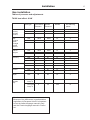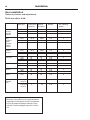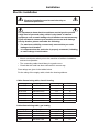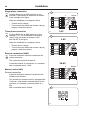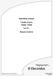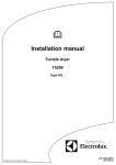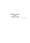
1
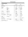
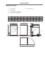
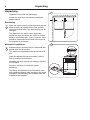
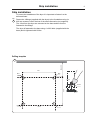
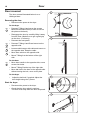
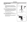
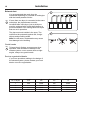
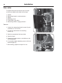
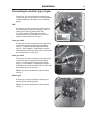
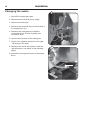
Installation manual
T4190
Compass Control
487 05 42 61.00
EN
Safety instructions
Safety instructions
This machine is only intended for drying water-washed
garments.
Clothes that have been cleaned with chemicals/inflammable
liquids, must NOT be dried in the machine.
Remove clothes from the tumble dryer as soon as they are dry.
This prevents them from becoming creased, and reduces the
risk of spontaneous ignition.
The machine must not be used for drying foam rubber or foamlike materials.
The machine must not be used for drying floor mops*.
The machine must not be used by minors.
The machine must not be hosed down with water.
Mechanical, electrical and gas installations must only be carried
out by authorised personnel.
If the machine has a fault, this must be reported as soon as
possible to the person in charge. This is important for your own
safety and for the safety of others.
Gas dryers only:
The machine is not to be installed in rooms containing cleaning
machines with perchloroethylene, TRICHLOROETHYLENE or
CHLOROFLUOROCONTAINING HYDROCARBONS as cleaning
agents.
What to do if you smell gas:
Do not try to light any appliance.
Do not touch any electrical switch; do not use any phone in
your building.
Evacuate the room, building or area.
Contact the laundry manager.
*Applies only to floor mops containing polypropylene.
The dryer must not be installed behind a lockable door or sliding
door. In the room where the dryer is to be installed the door hinges
must be on the outer side.
3
4
Contents
Contents
Safety instructions ........................................................................................ 3
Technical data .............................................................................................. 6
Unpackning .................................................................................................. 8
Ship installation ............................................................................................ 9
Door reversal .............................................................................................. 10
Installation ...................................................................................................11
Function check ........................................................................................... 21
The manufacturer reserves the right to modify design and material
specifications without notice.
5
Technical data
6
Technical data
Heating
Electric
Gas
Drum volume:
190 litres
190 litres
Weight:
Net
103 kg
103 kg
Drum:
Diameter
Depth
RPM
G-factor
680 mm
555 mm
50 rpm
0.8
680 mm
555 mm
50 rpm
0.8
Capacity:
Factor 1:25
Factor 1:33
7.5 kg
5.8 kg
7.5 kg
5.8 kg
Heat effect:
Electric
6.0 kW
8.0 kW
6.0 kW
8.0 kW
Air consumption:
Heat effect 6.0 kW
8.0 kW
270 m3/h
290 m3/h
270 m3/h
290 m3/h
Piping:
Evacuation
Ø 125
Ø 125
Gas piping
ISO 7/1 - R1/2
Pressure drop:
Evacuation 6.0 kW
8.0 kW
380 Pa
350 Pa
380 Pa
350 Pa
Sound power level:
LW
< 68 dB (A)
< 68 dB (A)
Technical data
7
Dimension sketch
1
Door opening
5
2
El. connection
3
Pipe connection, evacuation
4
Connection for external control
mm
A
720
B
745
mm
L
575
M
80
C
1130
A
D
420
Gas connection
E
110
F
120
B
G
960
H
45
I
55
K
1445
4
H
2
I
1
5
C
G
3
L
D
E
M
K
F
Unpacking
8
Unpacking
1
Unpack the dryer from the packaging.
Loosen the dryer from the pallet by cutting the
plastic ribbons.
Positioning
Fig
1
Place the tumble dryer to ensure that work can be
done as easily as possible by the user and the
service technician alike. The door hanging can be
changed.
The distance to the wall or other equipment
behind the dryer should be min. 300 mm and the
distance to the sides min. 10 mm. However, there
should be free access to the back of the dryer for
the purpose of servicing it.
Mechanical installation
Fig
2
Adjust the dryer to ensure that it is horizontal and
stands firmly on all four feet.
The maximum height adjustment of the feet is 50
mm.
When the adjustment has been made, lock the
feet by means of the lock-nuts.
Normally, the dryer requires no bolting to the floor
or foundation.
However, tumblers on a base do require
anchoring.
The fittings are fastened to the foundation using
M10 expansion bolts or other devices of the same
dimension. Special fittings are available from the
supplier for this purpose.
2
Ship installation
9
Ship installation
To ensure the steadiness of the dryer it is important to fasten it to the
delivered base.
Fig
1
Fasten the 4 fittings (supplied with the dryer) to the foundation using 4 x
M10 set screws or other devices of the same dimension (not supplied).
The 4 feet from the dryer are mounted on the base and the feet are
fastened to the fittings.
The dryer is fastened to the base using 4 x M10 bolts (supplied with the
base) and is tightened with 20 Nm.
Drilling template
Min 400
1
675
M10
M10
Dryer
20 Nm
600
M10
Front
M10
M10
Door
10
Door reversal
1
The door reversal illustrated below is on a
lefthinged door.
A
Reversing the door
• Disconnect the power to the dryer.
On the dryer
Fig
1
• Demount T-fitting A and screw the screws
back into the same holes (in order to secure
the plate on the back).
• Disengage the door by carefully lifting it away
from the front. (Make sure to get a good grip
on the door - it is heavy).
B
2
• Demount the front panel.
Fig
1
Fig
2
Fig
3
• Demount T-fitting A and B and mount on the
opposite side.
• Loosen cable hanger with cable and mount on
the opposite side. Strap the cable.
• Move door switch to the opposite side.
• Mount T-fitting A at the bottom of the right
side.
On the door
Fig
4
• Move door handle to the opposite side, screw
screws into holes.
• Mount T-fitting B at the top of the right side.
• Move ball lock in the door to the opposite side
without turning the lock, move cover plate.
On the dryer
•
Adjust the ball lock if required. Adjust the
door height using the T-pieces.
3
Start the dryer
• Reconnect the power to the dryer.
• Check that the door switch is working:
The drum must stop when the door is opened.
4
B
Installation
Evacuation system
11
1
Fresh-air
For maximum efficiency and the shortest
possible drying time, it is important to ensure
that fresh air is able to enter the room from the
outside in the same volume as that blown out of
the room.
Fig
1
5xA
To avoid a draught in the room, it is advisable to
place the air inlet behind the dryer. The area* of
the air inlet opening must be 5 times the size of
the vent pipe area. The resistance in the grating/
slats on the airinlet cover plate should not
exceed 10 Pa (0.1 mbar).
The air consumption is 400 m3/h.
Fig
2
*The area of the inlet opening is the area
through which the air can flow without resistance
from grating/slatted cover.
Note that gratings/slatted covers often block half
of the total fresh air vent area. Remember to
take this into account.
2
5xA
Installation
12
Exhaust duct
3
It is recommended that each dryer be
connected separately to a smooth air outlet pipe
with the lowest possible friction.
Fig
3
If more than one dryer is connected to the same
outlet pipe, the pipe diameter must be
increased after each dryer, just as all dryers
must be equipped with a back draft damper to
prevent humid air from running back into dryers
that are not in operation.
The pipe must end outside in the open. The
outlet must be protected against rain, foreign
objects and prevailing winds.
4
Note! In cold areas, condensation may cause
frost damage to the building.
Gentle bends
Fig
4
To keep the air flowing, ensure proper dryer
operation, and minimise lint buildup in the
exhaust system, never connect ducts at right
angles, always use gentle bends.
Service organisation/dealer
If you have questions relating to the design of
the exhaust system, please contact your local
dealer or service organisation.
No. of dryers
Outlet
m3/h
d
mm
Fresh-air intake
cm2
Pipe length 0-70 m
d
1
290
Ø125
400
Ø125
2
440
Ø125
800
Ø160
3
660
Ø125
1200
Ø200
4
880
Ø125
1600
Ø250
Installation
Gas installation
To be carried out by qualified personnel
Mount a manual shutt-off valve prior to the dryer.
The gas pipe to the dryer must be dimensioned to an output
of 6.6 kW / 8 kW.
From factory the nozzle pressure setting corresponds to the
heating value printed on the data label on the back of the dryer.
Check that the nozzle pressure and heating value are according
to the values given in the table. If not, contact the supplier.
Bleed the pipe system before connecting the dryer.
After connection, test all joints for leaks.
13
Installation
14
Gas valve
1
5
To adjust the pressure unscrew the 6 screws
on the cover plate at the back of the dryer.
1. Nozzle
2. Measuring branch, nozzle pressure
3. Nipple
4. Adjusting screw
5. Control Box, gas valve
6. Measuring branch, supply pressure
6
2
3+4
Test run
1. Loosen the measuring branch screw (2) anticlockwise a 1/4 of a turn.
2. Connect a manometer to measuring
branch (2).
3. Select a programme that uses heat.
2
4. Start the dryer.
5. Check the nozzle presure, see tables on the
following pages.
6. If necessary adjust adjusting screw (4) found
behind nipple (3).
7. After testing, prepare the dryer for use.
1
Installation
Converting to another type of gas
15
1
If the dryer is to be converted to another type
of gas, the gas nozzle and the air reducing plate
must be replaced, see tables on the following
pages.
LPG
If the dryer is to be converted to LPG, use the
air reducing plate and the matching nozzle. To
change the reducing plate follow step
3-7 in the chapter "Changing the nozzle".
Subsequently mount the plate in the 2 holes
and then follow step 8-9, see fig. 1.
Town gas 6 kW
If the dryer is to be converted to town gas 6 kW,
use the air reducing plate and the matching
nozzle. To change the reducing plate follow
step 3-7 in the chapter "Changing the nozzle".
Subsequently mount the plate in the 4 holes and
then follow step 8-9, see fig. 2.
2
Town gas 8 kW
If the dryer is to be converted to town gas 8 kW,
use the air reducing plate and the matching
nozzle. To change the reducing plate follow
step 3-7 in the chapter "Changing the nozzle".
Subsequently mount the plate in the 4 holes and
then follow step 8-9, see fig. 3.
Note! The burner bracket must be mounted,
see fig. 1.
Natural gas
3
If the dryer is to be converted to natural gas,
remove all air reducing plates.
Note! The burner bracket must be mounted,
see fig. 1.
Installation
16
Changing the nozzle
1
1. Shut off the manual gas valve.
2. Disconnect the electrical power supply.
3. Unscrew the back plate.
4. Dismount the electrode wire on the left side of
the heating box, fig 1.
5. Dismount the compression nut and the
compression ring. Pull the coupling from
the nozzle, fig 2.
6. Unscrew the 8 screws of the heating box.
7. Lift the cover upwards and pull it to the right
- still sitting on the edge.
8. Dismount the nozzle and replace it with the
right dimension, see tables on the following
pages.
9. Assemble in the opposite order as described
above.
2
Installation
17
Gas installation
Tables of pressure and adjustments
T4190 heat effect: 6 kW
Gas type
Connection
Pressure
Nozzle
Pressure
Nozzle
Air reducing
plates
Denmark
Norway
Sweden
Finland
LPG
GNH
30
20
30
8.2
3
2.35
A
Italy
England
Spain
Portugal
Ireland
Greece
LPG
GNH
28/37
20
28/37
8.2
1.3
2.35
A
France
Belgium
LPG
GNH
GNL
28/37
20/25
20/25
28/37
20/25
20/25
1.3
1.95
1.95
A
Germany
LPG
GNH
GNL
50
20
20
30
8.2
12.1
1.3
2.35
2.35
A
Holland
LPG
GNL
30
25
30
12.1
1.3
2.35
A
Austria
LPG
GNH
50
20
30
8.2
1.3
2.35
A
Japan
LPG
28
28
1.3
A
Denmark
Sweden
Italy
Town gas
Group a
8
4.5
3.95
B
Town gas
Group b
8
3.5
3.95
B
Note!
Because of the differences in gasinstallation
regulations in European Union it is important
to use the Italian-language manual in Italy
and the French-language manual in France
ect.
Installation
18
Gas installation
Tables of pressure and adjustments
T4190 heat effect: 8 kW
Gas type
Connection
Pressure
Nozzle
Pressure
Nozzle
Air reducing
plates
Denmark
Norway
Sweden
Finland
LPG
GNH
30
20
30
9
1.45
2.65
A
Italy
England
Spain
Portugal
Ireland
Greece
LPG
GNH
28/37
20
28/37
9
1.45
2.65
A
France
Belgium
LPG
GNH
GNL
28/37
20/25
20/25
28/37
20/25
20/25
1.45
2.2
2.2
A
Germany
LPG
GNH
GNL
50
20
20
30
9
13.4
1.45
2.65
2.65
A
Holland
LPG
GNL
30
25
28.8
13.4
1.25
2.65
A
Austria
LPG
GNH
50
20
30
9
1.25
2.65
A
Japan
LPG
28
28
1.45
A
Denmark
Sweden
Italy
Town gas
Group a
8
4.5
4.45
C
Town gas
Group b
8
3.5
4.45
C
Note!
Because of the differences in gasinstallation
regulations in European Union it is important
to use the Italian-language manual in Italy
and the French-language manual in France
ect.
Installation
19
Electric installation
Electrical installation must be carried out by an
authorized personnel!
It is important to know that the machines are designed to provide
a high level of personal safety, which is why items of external
equipment such as earth leakage circuit breakers are not necessary.
If you still want to connect your machine across an earth leakage
circuity breaker, please remember the following:
• For maximum reliability, connect only one machine per earth
leakage circuit breaker.
• It is important that the earth wire is properly connected, including
to earth leakage circuit breaker.
• Mount a multi-pole switch prior to the machine to facilitate installation
and service operation.
• The connecting cable should hang in a gentle curve.
• Check that the earth has been connected in correct way.
Fuse ratings are given in the tables below.
For the rating of the supply cable, check the local regulations.
Cable dimensioning table, electric heating
Heating type
Voltage type
Total rating kW
Fuse A
El. 6.0 kW
400-415V 3N AC
6.3
10
El. 6.0 kW
230-240V 1 AC
6.3
35
El. 6.0 kW
400-440V 3 AC
6.3
10
El. 6.0 kW
200-240V 3 AC
6.3
20
El. 8.0 kW
400-415V 3N AC
8.3
16
El. 8.0 kW
400-440V 3 AC
8.3
16
El. 8.0 kW
230-240V 3 AC
8.3
25
Total rating kW
Fuse A
Cable dimensioning table, gas heating
Heating type
Voltage type
Gas
400-415V 3N AC
0.25
10
Gas
400-480V 3 AC
0.25
10
Gas
200-240V 3 AC
0.25
10
Gas
230-240V 1 AC
0.25
10
Installation
20
Single-phase connection
Fig
6
6
Connect Earth wire to GND terminal, Live to
terminal L1 and Neutral to terminal N as shown
in the example in the figure.
GND
N
When the installation is completed, check:
L3
• That the drum is empty.
L2
L1
• Turn on the main switch and choose a drying
program. Start the machine.
Three phase connection
Fig
7
Connect Earth wire to GND terminal, Live to
terminal L1, L2, L3 and Neutral to terminal N
(3N AC only) as shown in example "3 AC"
and "3N AC" in the figure.
X1 X2
External connection
Max. 1.25A
1 AC
6309
7
3 AC
When the installation is completed, check:
GND
• That the drum is empty.
N
• Turn on the main switch and choose a drying
program. Start the machine.
L3
L2
L1
External connection (3NAC)
Fig
8
A special connection terminal is located at the
mains connection.
X1 X2
External connection
Max. 1.25A
6308
The connection terminal is used for:
Connection/control of external fan or a condeser.
3N AC
Max. connected load is 1.25A.
GND
Marine version (3AC)
N
External connection
L3
L2
A special connection terminal is located on the
tumbler motor bracket.
The terminal for external control is equipped with
110V/max. 100mA and is intended solely for the
operation of a contactor (external control of a
fan).
Max. connected load is 100mA.
L1
X1 X2
External connection
Max. 1.25A
6307
8
6330
Function check
Function check
21
1
Check that the drum is empty and the door has
been closed.
Start the dryer
Check that the door switch is working. The drum
must stop if the front door is opened.
Check the direction of rotation
Fig
1
This is done by selecting the “No heat”
programme.
• Start the dryer. Leave the dryer running for 30
seconds.
• Open the door quickly. Observe the direction
of rotation of the drum is clockwise.
Isolate the machines electrical supply - swap the
positions of the incoming supply phases at the
main terminal block - re-establish the supply and
re-test.
Final test
• Let the dryer work for 5 minutes on a program
that requires heat.
• Check that the heating is working by opening
the front door and feel the heat.
If the above test-points are in order, the dryer is
ready for use.
Service organisation / dealer
If deficiencies or a fault are detected, please
contact your local service organisation / dealer.
6311
www.electrolux.com/professional
Share more of our thinking at www.electrolux.com
about | case studies | contact
0845 077 65 65
Home
Laundry Equipment
Ozone Laundry Systems
Chemicals
Services
Special Offers
Ex Rental
Testimonials
Contact Us