1
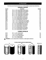
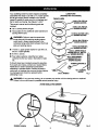
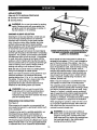
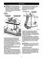
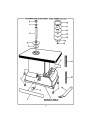
Owner's Manual
ICRlaFTSMRN'I
OSCILLATING SANDER
Double Insulated
Model No.
315.215700
Save this manual
future reference
,_
for
• Safety
• Features
CAUTION:
Read and follow
all Safety Rules and Operating
Instructions before first use of
this product.
Customer
Help Line: 1-800-932-3188
Sears, Roebuck and Co., Hoffman Estates, IL 60179
Visit the Craftsman web page: www.sears.com/craftsman
972000-481
10-00
•
•
•
•
USA
Adjustments
Operation
Maintenance
Parts List
®
•
Table Of Contents ..........................................................................................................................................
2
•
Warranty .........................................................................................................................................................
2
•
Introduction .....................................................................................................................................................
2
•
Rules For Safe Operation ...........................................................................................................................
3-5
•
Product Specifications ....................................................................................................................................
5
•
Labels .............................................................................................................................................................
6
•
Accessories ....................................................................................................................................................
7
•
Unpacking .......................................................................................................................................................
8
•
Features ....................................................................................................................................................
9-10
•
Adjustments .............................................................................................................................................
11-12
•
Operation .................................................................................................................................................
13-14
•
Maintenance .................................................................................................................................................
15
•
Exploded View and Repair Parts List ......................................................................................................
16-17
•
Parts Ordering / Service ...............................................................................................................................
FULL ONE YEAR WARRANTY
ON CRAFTSMAN
OSCILLATING
18
SANDER
If this rRWI=TSMRHOscillating Sander fails due to a defect in material or workmanship within one year from the
date of purchase, Sears will repair it free of charge.
Contact a Sears Service Center for repair.
If this product is used for commercial or rental purposes, this warranty applies for only 90 days from the date of
purchase.
This warranty gives you specific legal rights, and you may also have other rights which vary from state to state.
Sears, Roebuck and Co., Dept. 817WA, Hoffman Estates, IL 60179
Your oscillating sander has many features for making
operation more pleasant and enjoyable. Safety,
performance and dependability have been given top
priority in the design of this sander, making it easy to
maintain and operate.
CAUTION: Carefully read through this entire
owner's manual before using your new oscillating
sander. Pay close attention to the Rules For Safe
Operation, Warnings and Cautions. If you use
your sander properly and only for what it is
intended, you will enjoy years of safe, reliable
service.
_Look
for this symbol to point out important safety precautions.
Your safety is involved.
It means attention!!!
The purpose of safety symbols Is to attract your attention to possible dangers. The safety symbols, and
the explanations with them, deserve your careful attention and understanding. The safety warnings do
not by themselves eliminate any danger. The Instructions or warnings they give are not substitutes for
proper accident prevenUon measures.
SYMBOL
A
MEANING
SAFETY
ALERT
SYMBOL:
Indicates danger, warning, or caution. May be used in conjunction with other symbols or pictographs.
A
DANGER: Failure to obey a safety warning will result in serious injury to yourself or to others.
Always follqw the safety precautions to reduce the risk of fire, electric shock and personal injury.
A
WARNING:
Failure to obey a safety warning can result in serious injury to yourself or to others.
Always follow the safety precautions to reduce the risk of fire, electric shock and personal injury.
A
CAUTION: Failure to obey a safety waming may result in property damage or personal injury to
yourself or to others. Always follow the safety precautions to reduce the risk of fire, electric shock
and personal injury.
NOTE:
Advises you of information or instructions vital to the operation or maintenance of the equipment.
DOUBLEINSULATION
IMPORTANT
Double insulation is a concept in safety, in electric
power tools which eliminates the need for the usual
three-wire grounded power cord. All exposed metal
parts are isolated from internal metal motor
components with protecting insulation. Double
insulated tools do not need to be grounded.
Servicing of a tool with double insulation requires
extreme care and knowledge of the system and
should be performed only by a qualified service
technician. For service we suggest you return the tool
to your nearest Sears Store for repair. Always use
original factory replacement parts when servicing.
_
•
WARNING: Do not attempt to operate this tool
until you have read thoroughly and understand
completely all instructions, safety rules, etc.
contained in this manual. Failure to comply can
result in accidents involving fire, electric shock,
or serious personal injury. Save owner's manual
and review frequently for continuing safe
operation, and instructing others who may use
this tool.
and benches invite accident_.
•
•
KNOW YOUR POWER TOOL. Read owner's
Do not
KEEP CHILDREN AND VISITORS AWAY. All
•
MAKE WORKSHOP CHILD-PROOF with padlocks, master switches, or by removing starter
keys.
•
DO NOT FORCE TOOL. It will do the job better
and safer at the rate for which it was designed.
•
USE THE RIGHT TOOL. Do not force the tool or
KEEP THROAT PLATES IN PLACE and in
working order.
•
ENVIRONMENTS.
visitors should wear safety glasses and be kept at
a safe distance from the work area. Do not let
visitors contact tool or extension cord.
manual carefully. Learn its applications and
limitations as well as the specific potential hazards related to this tool.
•
AVOID DANGEROUS
use power tools in damp or wet locations. Do not
expose them to rain, water, or any wet conditions.
Keep the work area well lit.
READ ALL INSTRUCTIONS
•
KEEP WORK AREA CLEAN. Cluttered
areas
attachment to do a job for which it was not designed.
REMOVE WRENCH. Get in the habit of checking
to see that wrench is removed from the spindle
before turning sander on. Return wrench, upper
spindle washer(s), and throat plates to storage
area when not in use.
•
DRESS PROPERLY. Do not wear loose clothing,
gloves, neckties, rings, bracelets, or other jewelry
that could get caught in moving pads. Nonslip
3
RULES
FOR SAFE OPERATION
(Continued)
footwear Is recommended. Wear protective hair
covering to contain long hair.
•
•
ALWAYS WEAR SAFETY GLASSES WITH
SIDE SHIELDS. Everyday eyeglasses have only
impact-resistant lenses; they are NOT safety
glasses.
•
PROTECT YOUR LUNGS. Wear a face or dust
mask.
•
PROTECT YOUR HEARING. Wear hearing
protection during extended periods of operation.
•
SECURE THE WORK. Support work securely on
the table and hold with both hands.
•
DO NOT OVERREACH.
balance at all times.
•
MAINTAIN TOOLS WITH CARE. Keep tools
maintained and clean for the best and safest
MAKE SURE YOUR EXTENSION CORD IS IN
GOOD CONDITION. When using an extension
cord, be sure to use one heavy enough to carry
the current your product will draw. An undersized
cord will cause a drop in line voltage resulting in
loss of power and overheating. A wire gage size
(A.W.G.) of at least 16 is recommended for an
extension cord 100 feet or less in length. A cord
exceeding 100 feet is not recommended. If Jn
doubt, use the next heavier gage. The smaller the
gage number, the heavier the cord.
Keep proper footing and
USE OUTDOOR
•
EXTENSION CORDS. When
tool is used outdoors, use only extension cords
intended for use outdoors and so marked. Outdoor approved cords are marked with the suffix
W-A, for example -- SJTW-A or SJOW-A.
performance. Follow instructions for cleaning,
lubdcating, and changing accessories.
•
DON'T ABUSE CORD. Never yank cord to
disconnect from receptacle. Keep cord from heat,
oil, and sharp edges.
POLARIZED PLUGS. To reduce the risk of
AFTER TURNING OFF POWER SWITCH,
DISCONNECT TOOL and wait for spindle to stop
before servicing. Sander must be disconnected
from the power when not in use or when changing
accessories, sanding sleeves, rubber spindles, or
other items listed in this Owner's Manual.
electric shock, this tool has a polarized plug (one
blade is wider than the other). This plug will fit in a
polarized outlet only one way. If the plug does not
fit fully in the outlet, reverse the plug. If it still does
not fit, contact a qualified electrician to install the
proper outlet. Do not change the plug in any way.
TO REDUCE THE RISK OF ACCIDENTAL
KEEP HANDS AWAY FROM SANDING AREA.
STARTING, make sure the switch is in the OFF
position before plugging in the tool.
Keep hands away from sanding sleeve. Do not
reach underneath work or around sanding sleeve
while spindle is rotating.
USE RECOMMENDED ACCESSORIES. Refer to
this owner's manual for recommended accesso-
NEVER USE IN AN EXPLOSIVE
ries. Using improper accessories may result in a
risk of personal injury.
ATMOSPHERE. Normal sparking of the motor
could ignite fumes,
NEVER STAND ON TOOL. Serious injury could
occur if the tool is tipped or if sanding sleeve is
unintentionally contacted.
KEEP TOOL DRY, CLEAN, AND FREE FROM
OIL AND GREASE. Always use a clean cloth
when cleaning. Never use brake fluids, gasoline,
petroleum-based products, or any solvents to
clean tool,
CHECK DAMAGED PARTS. Before the tool is
used again, a guard or other part that is damaged
should be carefully checked to determine that it
will operate properly and perform its intended
function. Check for alignment of moving pads,
binding of moving parts, breakage of parts,
mounting, and any other conditions that may
,affect operation. A guard or other part that is
damaged should be properly repaired or replaced
by an authorized service center.
BE AWARE OF THE CORRECT
STAY ALERT AND EXERCISE CONTROL.
Watch what you are doing and use common
sense. Do not operate tool when you are tired. Do
not rush.
DIRECTION OF
•
DO NOT USE TOOL IF SWITCH DOES NOT
TURN IT ON AND OFF. Have defective switches
replaced by an authorized service center.
•
ALWAYS TURN OFF SANDER before disconnecting it to avoid accidental starting.
FEED. Feed workpiece into sanding sleeve
against the direction of rotation of the sanding
sleeve only.
•
NEVER USE THIS OR ANY POWER SANDER
FOR WET SANDING. Failure to comply can
result in electrical shock causing serious injury or
worse.
NEVER LEAVE TOOL RUNNING UNATTENDED. TURN OFF THE POWER. Do not leave
tool until it comes to a complete stop.
4
RULES
•
FOR SAFE OPERATION
(Continued)
INSPECT FOR and remove all nails from lumber
before sanding.
•
DRUGS, ALCOHOL,
MEDICATION.
Do not
operate tool while under the influence of drugs,
alcohol, or medication.
WHEN SERVICING USE ONLY IDENTICAL
CRAFTSMAN REPLACEMENT PARTS.
SAVE THESE INSTRUCTIONS.
Refer to them
frequently and use to instruct other users. If you
loan someone this tool, loan them these instructions also.
_k
WARNING:
Some dust created by power
sanding, sawing, griq.ding,drilling, and other
construction activities contains chemicals known
to cause cancer, birth defects or other
reproductive harm. Some examples of these
chemicals are:
PRECAUTIONS
PAINT
TO TAKE WHEN SANDING
Sanding of lead based paint is NOT
RECOMMENDED. It is very difficult to control the
contaminated dust that could cause lead poisoning.
It is also difficult to identify whether or not a paint
contains lead. Therefore, we recommend the following
precautions when sanding all paints:
•
PROTECT YOUR LUNGS. Wear a dust mask or
respirator at all times. Wear only dust masks that
are suitable for working in lead paint sanding
environments. Ordinary painting masks do not
offer this protection.
•
DO NOT ALLOW CHILDREN OR PREGNANT
WOMEN TO ENTER THE WORK AREA UNTIL
PAINT SANDING JOB IS FINISHED AND ALL
CLEAN UP COMPLETED.
TO PREVENT INGESTING CONTAMINATED
• lead from lead-based paints,
PAINT PARTICLES, DO NOT EAT, DRINK, OR
SMOKE IN A WORK AREA WHERE PAINT IS
BEING SANDED. After sanding paint, wash and
clean up before eating, drinking, or smoking. Do
not leave food, drinks, or tobacco products in the
work area where dust can settle on them.
• crystalline silica from bricks and cement
and other masonry products, and
• arsenic and chromium from chemicallytreated lumber.
Your risk from these exposures varies,
depending on how often you do this type of
work. To reduce your exposure to these
chemicals: work in a well ventilated area, and
work with approved safety equipment, such as
those dust masks that are specially designed
to filter out microscopic particles.
•
PROTECT THE ENVIRONMENT
WHEN
SANDING PAINT. Use a dust collection system
if possible. Seal the work area with plastic if
necessary. DO NOT track paint dust outside the
work area.
•
THOROUGHLY CLEAN THE WORK AREA
UPON COMPLETION OF PAINT SANDING
PROJECT. If project lasts for an extended period
of time, clean work area often. Items such as
sanding dust, vacuum filtePbags, plastic drop
cloths, etc. should be placed in a sealed
container and disposed of properly. Clean all
items exposed to sanding dust.
WARNING:
The operation of any oscillating sander can result in foreign objects being thrown into your
eyes, which can result in severe eye damage. Before beginning power tool operation, always
wear safety goggles or safety glasses with side shields and a full face shield when needed.
We recommend Wide Vision Safety Mask for use over eyeglasses or standard safety glasses
with side shields, available at Sears Retail Stores.
SAVE THESE INSTRUCTIONS
Oscillating Range
Sanding Sleeve Capacity
Sanding Sleeve Height
Sanding Thickness
No Load Speed
Oscillations Per Minute
Toggle Switch w/Removable Key
518 in.
1/2 in. - 3 in.
4-1/2 in.
3-11/16 in.
2000 RPM
58 OPM
Table Size
Spindle Size
Rating
Input
Dust Collection Capacity
Net Weight
20 in. x 14 in.
1/2 in.
120 volts, 60 Hz, AC only
3-1/2 Amperes
2-1/4 in. Outlet
26 Lbs.
Thefollowing
labels are on the oscillating sander with locations indicated.
Oscillating Sander
Double Insulated 2000 RPM
110-120VOLTS ACONLY 60Hz 3.SAMPS
MODEL 315.215700
WARNING:
us=o_y_
_PARTS.
Customer Help Line 1-800-932-3188
WARNING
ADVERTENCIA
• Do notremovethis cover;No serviceable
parts inside.
• No sacar estatapa: No hayningunapieza
en el interiorque puedaser reparadapor
el usuario.
I
Oscillating
Spindle Sander
6
I
Thefollowing
recommended accessories are currently available at selected Sears Retail Stores.
SANDING
Item No.
SLEEVES
Description
Quantity
28050
1/2 in. x 4-1/2 in. Sanding Sleeve 50 Grit Coarse
3 ea.
28051
1/2 in. x 4-1/2 in. Sanding Sleeve 80 Grit Medium
3 ea.
28052
1/2 in. x 4-1/2 in. Sanding Sleeve 150 Gdt Fine
3 ea.
28053
3/4 in. x 4-1/2 in. Sanding Sleeve 50 Gdt Coarse
3 ea.
28054
3/4 in. x 4-1/2 in. Sanding Sleeve 80 Gdt Medium
3 ea.
28055
3/4 in. x 4-1/2 in. Sanding Sleeve 150 Gdt Fine
3 ea.
28056
1 in, x 4-1/2 in. Sanding Sleeve 50 Gdt Coarse
3 ea.
28057
l_in. x 4-1/2 in, Sanding Sleeve 80 Grit Medium
3 ea.
28058
1 in. x 4-1/2 in. Sanding Sleeve 150 Gdt Fine
3 ea.
28059
1-1/2 in. x 4-1/2 in. Sanding Sleeve 50 Grit Coarse
2 ea.
28110
1-1/2 in. x 4-1/2 in. Sanding Sleeve 80 Grit Medium
2 ea.
28111
1-1/2 in, x 4-1/2 in. Sanding Sleeve 150 Grit Fine
2 ea.
28112
2 in. x 4-1/2 in. Sanding Sleeve 50 Grit Coarse
2 ea.
28113
2 in. x 4-1/2 in. Sanding Sleeve 80 Gdt Medium
2 ea.
28114
2 in. x 4-1/2 in, Sanding Sleeve 150 Grit Fine
2 ea.
28115
3 in. x 4ol/2 in. Sanding Sleeve 50 Grit Coarse
1 ea.
28116
3 in. x 4-1/2 in. Sanding Sleeve 80 Grit Medium
1 ea.
28117
3 in. x 4-1/2 in. Sanding Sleeve 150 Grit Fine
1 ea.
RUBBER SPINDLES
_,
28118
3/4 in. x 4-1/2 in. Rubber Spindle
1 ea.
28119
1 in. x 4-1/2 in. Rubber Spindle
1 ea.
28120
1-1/2 in. x 4-1/2 in. Rubber Spindle
1 ea.
28121
2 in. x 4-1/2 in. Rubber Spindle
1 ea.
28122
3 in. x 4-1/2 in. Rubber Spindle
1 ea.
WARNING: The use of attachments or accessories not listed might be hazardous.
OPTIONALSANDINGSLEEVESANDRUBBERSPINDLES
3 in.
2 in.
1-1/2in.
C_
7
3/4 In.and I In.
Youroscillating
sander
has been shipped completely
assembled and ready to use with a 1 in. rubber spindle
LOOSEPARTS
(PROVIDEDWITHTHISSANDER)
and 80 grit sanding sleeve installed on the spindle.
Inspect it carefully to make sure it is not damage and
that no parts are missing. See Figures I and 2.
THROATPLATES
/__,_
-3/16
In. DIA. FOR3 In.
SANDINGSLEEVES
This owner's manual and the following parts are
included:
• 1/2 in. sanding sleeve (SO grit).
• Throat plates for five additional rubber spindle and
__.j/
_
sandingsleevesizes.
_
_1= WARNING: Failure to use the correct size
_
_
f_=_--_=_
1-21/32
in.DIA.FOR I-IQin.
SANDING SLEEVES
'`d_
throat plate with its'matching sanding sleeve
could result in fingers being pinched or the
workpiece being pulled down between the throat
I,J_
_
plate and sanding sleeve.
_
J
¢F__fN_._..._
I
O
_
SANDINGSLEEVES
_ 1-13/16In. UPPERSPINDLE
J WASHERFOR2 In. AND 3 In.
•
1-13/16 in. upper spindle washer for use with 2 in.
and 3 in. rubber spindles.
•
•
A 9/16 in. wrench.
Four rubber cushions. Install the four rubber
cushions into the four holes in the bottom of cabinet.
_._
_ J
J
(
y.---
_
_
_
V
_
If all parts have been included, proceed to operation.
If any parts are missing, contact your nearest Sears
Retail Store to obtain replacement parts before
attempting to operate sander. Examine all parts to
make sure no breakage has occurred during shipping.
Any damaged part should be replaced before
attempting to use,
_
2-3/16in. DIA. FOR2 In.
/SANDING
SLEEVES
_'_
15/16In. DIA. FOR3/4 In.
SANDINGSLEEVES
11116in. DIA. FOR 1/2 In.
SANDINGSLEEVES
518In.UPPER SPINDLE
_,.WASHER FOR 1/2 In.
SANDINGSLEEVES
RUBBERCUSHIONS(4)
1/2 In. SANDING
SLEEVE
9/16in. WRENCH
Fig, 1
WARNING: If any parts are missing, do not operate your sander until the missing parts are replaced.
Failure to do so could result in possible serious personal injury.
215700 OSCILLATING SANDER
RUBBERCUSHION
CABINET
Fig. 2
8
Youroscillatingsanderhasbeendesigned
TABLE SIZE
for fast
smooth sanding of curved and irregular shaped wood
surfaces. When used properly and only for what it is
intended, this versatile sander will give you years of
trouble-free performance. It is professionally
engineered, but its ease of operation allows the
amateur to produce work which is beautiful and
precise. It is suitable for sanding with coarse, medium,
and fine grit sanding sleeves.
OSCILLATING
The sanding table provides ample sanding space for
most workpieces. The table top is 20 in. long x 14 in.
wide.
ON/OFF SWITCH AND KEY
The ON/OFF switch has a built-in locking feature
which requires a key to be inserted before the sander
can be turned on. Pushing the toggle switch to OFF
position and removing the key locks the sander
against unintentional use. This feature is intended to
prevent unauthorized and possible hazardous use by
children and others.
MOTION
As the name implies, the most unique feature of this
sander is the fact that it oscillates. This means that the
spindle rises and falls as+t rotates. The oscillating
range for your sander is 5/8 in.
SANDING
CAPACITIES
This sander accepts 1/2 in. thru 3 in. sanding sleeves
that are 4-1/2 in. tall.
Note: Sanding sleeves are 4-1/2 in. tall, however you
can only sand material up to 3-11/16 in. thick.
The 1/2 in. sanding sleeve fits directly on the 1/2 in.
spindle and requires no rubber spindle. It is secured in
place with a washer and hex nut on top of the spindle.
All other sanding sleeves require a rubber spindle to
secure them in place. These different size rubber
spindles fit on the spindle and require a throat plate
and sanding sleeve for each size. A washer and hex
nut threaded on top of the spindle secures everything
in place.
_Ib
WARNING:
Always lock the switch oFF when
not in use. Remove key and keep in a safe
place, In the event of power failure, turn the
switch OFF and remove key. This will prevent
sander from accidentally starting when power
returns.
PLATE / WRENCH
STORAGE
AREA
Your sander has a throat plate and wrench storage
area located on the backside of the cabinet. See
Figure 3. Proper storage of throat plates and wrench
when not in use will help reduce the possibility of their
getting lost. You can also use this area for storing
upper spindle washers behind threat plates.
SANDING
STORAGE
SLEEVE
AREA
AND RUBBER
SPINDLE
Your sander has a sanding sleeve and rubber spindle
storage area located on the right side of the cabinet.
See Figure 3. When changing from one size sanding
sleeve and rubber spindle to another, store unused
ones on their designated pins. Proper storage of
sanding sleeves and rubber spindles when not in use
will help protect them from being damaged and from
getting lost.
3.5 AMP MOTOR
Your sander has a 3.5 amp motor with sufficient
power to handle tough sanding jobs. It develops a no
load speed of 2,000 rpm and 58 opm.
CAPABILITY
A standard 2-1/4 in. dust exhaust port has been
provided to make dustless sanding possible. See
Figure 3. It is located under the table top on the left
side of your sander. The pickup adapter end of a
vacuum hose fits inside the dust exhaust port with a
wedge fit type connection.
ACCEPTS
SLEEVES
CAUTION:
Removing the key does not lock the
switch until the switch is in the OFF position.
THROAT
The rubber spindle expands against the inner wall of
the sanding sleeve when the hex nut is tightened
against the washer. A 9/16 in. wrench has been
provided to tighten and loosen the hex nut,
DUST COLLECTION
_k
ELECTRICAL
CONNECTION
Your sander has a precision built electric motor. It
should be connected to a power supply that Is 120
volts, 60 Hz, AC only (normal household current).
Do not operate this tool on direct current (DC). A
substantial voltage drop will cause a loss of power
and the motor will overheat. If your sander does not
operate when plugged into an outlet, double-check
the power supply.
OPTIONAL SIZES OF SANDING
AND RUBBER SPINDLES
Optional sanding sleeves and rubber spindles available are shown on page 7. For a complete listing of
accessories that are available, refer to page 7.
9
KNOWYOUROSCILLATINGSANDER
Beforeattempting
to useanytool,familiarize yourself
with all operating features and safety requirements. See
Figure 3.
RUBBERSPINDLEAND
SANDINGSLEEVESTORAGEAREA
9/16in,
SPINDLE
THROATPLATES
HEXNUT
TABLETOP
UPPERSPINDLEWASHER
(THREESUPPUED)
5/8 In., 7/8 In., AND 1-13/16In.
THROAT
PLATE
THROATPLATE,
WRENCH,AND UPPERDRUM
WASHERSTORAGEAREA
1 In. SANDINGSLEEVE
DUSTEXHAUSTPORT
(SEE RGURE 10)
SLEEVE
TOSTART
SANDER
1/4 In.
MOUNTINGHOLES
TO STOPSANDER
INSERTSWITCHKEY
TO UNLOCKSWITCH
CUSHIONS
SWITCHKEY
FOLLOWARROWSTO STARTANDSTOPSANDER,LOCKAND
UNLOCKSWITCH,AND INSERTANDREMOVESWITCHKEY
REMOVESWITCHKEYTO LOCK
SWITCHWHENIN OFF POSITION
Fig. 3
_1_ WARNING:
Do not allow familiarity with tools to make you careless. Remember that a careless fraction of
a second is sufficient to inflict severe injury.
10
,_
•
WARNING:
Your sander should never be
connected to power supply when you are
assembling parts; making adjustments;
changing, installing, or removing sanding
sleeves; changing, installing, or removing rubber
spindles; changing, installing, or removing threat
plates; or when not in use. Placing switch in OFF
position, disconnecting sander, and removing
switch key will prevent accidental starting that
could cause serious injury.
,_
SANDING
SLEEVES
All except 1/2 in.
See Figures 4 and 5.
•
Grasp and hold sanding sleeve on spindle and
loosen hex nut using the 9/16 in. wrench provided.
If hex nut is too tight and spindle shaft spins inside
sanding sleeve, grasp the flats on top of spindle
shaft with a 114 in. wrench (not provided) and
loosen hex nut.
•
Remove hex nut, upper spindle washer, sanding
sleeve, rubber spindle, and throat plate.
•
Remove lower spindle washer end clean sawdust
accumulations:
Note: It is recommended that you clean sawdust
accumulations from threat plate, throat plate nest and
under lower spindle washer after each use.
FLATS
TO INSTALL:
TO LOOSEN
HEXNUT
•
THROATPLATE
WRENCH
TOTIGHTEN
HEXNUT
•
Select and install the appropriate throat plate that
provides the smallest clearance between desired
sanding sleeve and throat plate opening.
•
Select and install desired rubber spindle on
spindle.
•
Install appropdate sanding sleeve on rubber
spindle.
Fig. 4
UPPER _
SPINDLEWASHER
LOWER
SPINDLEWASHER
Replace lower spindle washer.
Note: Fin side of washer must always be installed
down. The fins help push sawdust through the dust
exhaust port opening, preventing buildup of
sawdust. Sawdust buildup in this area may cause
the oscillating motion to stop. Lower spindle
washer must be used with ell sanding sleeves.
SANDINGSLEEVE
HEX NUT__
WARNING:
Failure to unplug your sander
could result in accidental starting, causing
serious injury.
TO REMOVE:
As mentioned previously, your sander has been
shipped completely assembled with a 1 in. sanding
sleeve installed. The throat plate with a 1-3/16 in.
opening has been used. When changing sanding
sleeve sizes, change as follows:
TO CHANGE/INSTALL
Place switch in OFF position, remove switch key,
and unplug your sander.
/'_-
-"_-]
/
THROAT
PLATE
I
F"_'_
I
•
Note: If sanding sleeve becomes difficult to install
or remove, apply talcum powder on rubber spindle
or inside sanding sleeve before installing on rubber
spindle.
Install upper spindle washer and hex nut.
Note: The 7/8 in. washer should be used for 3/4
in., 1 in., and 1-1/2 in. rubber spindles. The 1-13/16
in. washer must be used for 2 in. and 3 in. rubber
SANDING
SLEEVE
(FIN SIDE DOWN)'_
spindles.
•
Grasp and hold sanding sleeve and tighten hex
nut, using the 9/16 in. wrench provided. Tighten
hex nut only enough to expand rubber spindle
against inner wall of sanding sleeve. Do not
overUghten.
•
Remove wrench and return it to wrench storage
area before connecting sander to a power supply.
WRENCH
PLATENEST
Fig. 5
11
TO CHANGE/INSTALL
1/2 In. SANDING
Note: Fin side of washer must always be installed
down. The fins help push sawdust through the dust
exhaust port opening, preventing buildup of
sawdust. Sawdust buildup in this area may cause
oscillating motion to stop. Lower spindle washer
must be used with all sanding sleeves.
SLEEVES
See Figures 4 and 6.
•
Place switch in OFF position, remove switch key,
and unplug your sander.
A
WARNING:
Failure to unplug your sander could
result in accidental starting, causing sedous
injury.
•
Install throat plate with the 11116 in. throat plate
opening.
•
Install 112 in. sanding sleeve on spindle shaft.
RUBBERSPINDLENOT USED
WITH 1/2In. SANDINGSLEEVES
Note: Sanding sleeve mounts directly onto spindle
shaft for 1/2 in. sleeves. Rubber spindle is not
required.
UPPERSPINDLE
WASHER
•
SANDINGSLE
Install upper spindle washer and hex nut.
Note: The 5/8 in. washer should be used.
LOWER
SPINDLEW/kSHER
(RN SIDE DOWN)
/
THROATP!_,ATE
•
Grasp and hold sanding sleeve and tighten hex
nut, using the 9/16 in. wrench provided. Tighten
hex nut securely. Do not overtlghten.
•
Remove wrench and return it to wrench storage
area before connecting sander to a power supply
source.
THROAT
PLATE
SELECTION
See Figure 7.
WRENCH
SANDINGSLEEVE
THROATPLATE
OPENING
THROATPLATE
Fig. 6
TO RE MOVE:
•
Grasp and hold sanding sleeve on spindle and
loosen hex nut using the 9/16 in. wrench provided.
If heJ(nut is too tight and spindle shaft spins inside
sanding sleeve, grasp the flats on top of spindle
shaft with a 1/4 in. wrench (not provided) and
loosen hex nut.
•
Remove hex nut, upper spindle washer, sanding
sleeve, rubber spindle, and throat plate.
•
Remove lower spindle washer and clean sawdust
accumulations.
Note: We recommend that you clean sawdust
accumulations from threat plate, throat plate nest
and under lower spindle washer after each use.
MAKESANDINGSLEEVEAND THROATPLATESELECTIONS
THATPROVIDE
THELEASTAMOUNTOFCLEARANCE
BETWEEN
THESANDINGSLEEVEANDTHROATPLATEOPENING.
Fig. 7
When changing sanding sleeves from one size to
another, always use the throat plate that provides the
least amount of clearance between sanding sleeve
and throat plate opening. Six throat plates have been
provided with this sander. The following chart identifies the diameter of sanding sleeve sizes and matching throat plate openings that should be used together. It also identifies upper spindle washer that
should be used with each size.
TO INSTALL:
•
Replace lower spindle washer.
Sanding Sleeve Diameter
1/2 in.
3/4 in.
1 in.
1-1/2 in.
2 in,
3 in.
Throat Plate Opening Diameter
11/16 in.
15/16 in.
1-3/16 in.
1-21132 in.
2-3/16 in.
3-3/16 in.
12
Upper Spindle Washer Slzo
5/8 in.
7/8 in.
7/8 in.
7/8 in.
1-13/16 in.
1-13/16 in.
APPLICATIONS
(Use only for the purposes listed below)
•
Sanding on wood surfaces.
•
Sanding plastics.
,_l
WARNING:
Do not use this sander for sanding
metals. Sanding metals will cause sparks that
will ignite wood and dust particles on sander, in
the dust collector, or in workshop.
SANDING SLEEVE SELECTION
Selecting the correct size diameter, correct size grit,
and correct type sanding Sleeve is an extremely
important step in achieving a high quality sanded
finish. Aluminum oxide, silicon carbide, and other
synthetic abrasives are best for power sanding.
Natural abrasives, such as flint and garnet are too soft
for economical use in power sanding.
SANDERSHOWNMOUNTEDTO A MOUNTINGBOARDFOR
PORTABLEAPPLICATIONS.
ALSOSHOWNSECURELY
CLAMPEDTO A WORKBENCH.
Fig. 8
In general, coarse grit will remove the most material
and finer grit will produce the best finish in all sanding
operations. The condition of the surface to be sanded
will determine which grit will do the job. If the surface
is rough, start with a coarse grit and sand until the
surface is uniform. Medium grit may then be used to
remove scratches left by the coarser grit and finer grit
used for finishing of the surface. Always continue
sanding with each grit until surface is uniform.
Mount sander to board using holes in cabinet as a
template for hole pattern. A 1/4 in. hole is located on
each of the four corners of the cabinet. Use 1/4 in.
bolts for securing sander to a workbench or mounting
board. If lag bolts are used, make sure they are long
enough to go through holes in sander, holes in
cushions and material sander is being mounted to. If
machine bolts are being used, make sure bolts are
long enough to go through holes in sander cabinet,
holes in cushions, material being mounted to, lock
washers, and hex nuts.
Note: Oo not use sander without a sanding sleeve,
Doing so will damage the rubber spindle.
Select and install the desired sanding sleeve for your
particular application. As mentioned previously,
sanding sleeves from 1/2 in. to 3 in. can be used with
this sander. Choose one that is close in size to the
workpiece you are sanding. Also install the
appropriate throat plate, with the least amount of
clearance for the sanding sleeve you choose.
_k
Note: It may be necessary to countersink hex nuts
and washers on bottom side of mounting board.
The supporting surface where sander is mounted
should be examined carefully after mounting to make
sure that no movement during use can result. If any
"tipping" or "walking" is noticed, secure workbench
legs or supporting surface before beginning sanding
operations. Support workpiece with miter gage,
backstop or worktable. A worktable should be a stable
support. A backstop is a support for the workpiece.
WARNING:
Failure to use the correct size
throat plate with its matching sanding sleeve
could result in fingers being pinched or the
workpiece being pulled down between the throat
plate and sanding sleeve.
PREPARING
FOR OPERATION
When preparing for operation, make sure hex nut on
top of spindle is tightened securely. Also make sure
that wrench has been removed from hex nut and
returned to wrench storage area.
See Figure 8.
When preparing for operation we recommend that
your sander be secured in a permanent location such
as to a workbench.
If sander is to be used in a portable application, we
recommend that you fasten it permanently to a
mounting board that can easily be clamped to a
workbench or other supporting surface. See Figure 8.
_k
The mounting board should be of sufficientsize to avoid
tipping of sander while in use. Any good grade plywood
or chipboard with a 3/4 in. thickness is recommended.
13
WARNING: Do not wear loose clothing or
jewelry when operating sander. They could get
caught in moving parts, causing serios injury.
Keep head away from sander and sanding area.
Hair could get caught in the rotating parts,
causing serious personal injury,
_i
spinning sanding sleeve will tend to throw or bounce
the workpiece away from the sanding sleeve. This
could cause loss of control of workpiece.
WARNING:
Always wear safety goggles or
safety glasses with side shields when using your
sander. Failure to do so could result in dust,
shavings, loose particles, or foreign objects
being thrown in your eyes, resulting in possible
serious injury. If the operation is dusty, also wear
a face or dust mask.
DUST COLLECTION CAPABILITY
See Figure 10.
DUSTEXHAUSTPORT
PICKUPADAPTER
ENDOF VACUUM
SANDING
See Figure 9.
DIRECTIONOF FEED
OF WORKPIECE
DIRECTIONOF ROTATION
OF SANDINGSLEEVE
Fig. 10
A standard 2-1/4 in. dust exhaust port has been
provided to make dustless sanding possible. It is
located under the table top on the left side of your
sander as shown in figure 10. The pickup adapter end
of a vacuum hose fits inside the dust exhaust port with
a wedge fit type connection.
Fig. 9
Even with a dust collection system, it is necessary to
periodically clean sanding dust from the throat plate
area. After extended use, sanding dust builds up under
the throat plate and forces its way into the throat plate
nest. Sanding dust build up in this area may cause
throat plate surface to rise and be above the table
surface.
Insert the switch key and tum sander on, Let the
motor build to its full speed, then gradually feed
workpiece against sanding sleeve. Do not let the
workpiece contact sanding sleeve before turning on
sander and allowing it to develop full speed.
Do not force. Exercise caution! You will become
familiar with the sander's features from practice and
use. If at all possible, always sand with a scrap piece
of the same wood, beforehand.
_i
Always Remain alert! Do not operate sander when
fatigued, or under the influence of alcohol or drugs.
WARNING:
Do not use this sander for sanding
metals. Sanding metals will cause sparks that
will ignite wood and dust particles on sander, in
dust collector, or in workshop.
TRANSPORTING
FEED DIRECTION
SANDER
When using your sander in a portable application, it is
acceptable to lift and carry sander by the table top. Be
careful when transporting to avoid dislodging throat
plates, wrench, and upper spindle washers from their
respective storage areas. Also be careful not to lose
any parts when transporting.
When sanding, the sanding sleeve rotates counterclockwise. Therefore, you should feed the workpiece
against the sanding sleeve from right to left as shown
in figure 9. When fed from right to left, the rotation of
the sanding sleeve sands against the workpiece. If fed
in the opposite direction, the rotation forces of the
14
_i
EXTENSION CORDS
WARNING:
When servicing, use only identical
Craftsman replacement pads. Use of any other
part may create a hazard or cause product
damage.
The usa of any extension cord will cause some loss of
power. To keep the loss to a minimum and to prevent
tool overheating, use an extension cord that is heavy
enough to carry the current the tool will draw.
GENERAL
A wire gage size (A.W.G.) of at least 16 is
recommended for an extension cord 100 feet or
less in length. When working outdoors, use an
extension cord that is suitable for outdoor use.
The cord's jacket will be marked WA.
Only the parts shown on parts list, page seventeen,
are intended to be repaired or replaced by the
customer. All other parts represent an important part
of the double insulation system and should be
serviced only by a qualified Sears service technician.
,_
Avoid using solvents when cleaning plastic pads. Most
plastics are susceptible tO'various types of commercial
solvents and may be damaged by their use. Use clean
clothe to remove dirt, dust, etc.
_L
CAUTION: Keep extension cords away from
the cutting area and position the cord so that it
will not get caught on lumber, tools, etc., during
sanding operation.
A
WARNING:
Do not at any time let brake fluids,
gasoline, petroleum-based products, penetrating
oils, etc. come in contact with plastic parts. They
contain chemicals that can damage, weaken, or
destroy plastic.
WARNING:
Check extension cords before each
use. If damaged replace immediately. Never use
tool with a damaged cord since touching the
damaged area could cause electdcal shock
resulting in serious injury.
Extension cords suitable for use with your sander are
available at your nearest Sears Retail Store.
It has been found that electric tools are subject to
accelerated wear and possible premature failure when
they are used on fiberglass boats, sports care,
wallboard, spackling compounds, or plaster. The
chips and grindings from these materials are highly
abrasive to electric tool parts such as bearings,
brushes, commutators, etc. Consequently, it is not
recommended that this tool be used for extended
work on any fiberglass material, wallboard, spackling
compounds, or plaster. During any use on these
materials it is extremely important that the tool is
cleaned frequently by blowing with an air jet.
d_i, WARNING:
Always wear safety goggles or
safety glasses with side shields during power tool
operation or when blowing dust. If operation is
dusty, also wear a dust mask.
Remember: It is recommended that you use this
sander for sanding wood and plastics only.
15
" CRAFTSMAN
OSCILLATING
SANDER
- MODEL
NUMBER
315,215700
10
7---,zp
11
€:
12
13
14
"!r
5
¢€_----.-16
4
9
17
18
/
/
2
SEE NOTE "A"
ii
ii
i
i
i
i|
.,
_6
,
...............
PAGE 17
o_,,
..
CRAFTSMAN
I
OSCILLATING
SANDER
- MODEL
NUMBER
315.215700
The model
number
will be found
on a plate
attached
to the rearSANDER
of the cabinet.
mention
model
number
in all
correspondence
regarding
your
OSCILLATING
or whenAlways
ordering
repairthe
parts.
J
|
PARTS LIST
Key
No.
Number
I
662681-001
Cushion ...........................................................................................
4
2
976863-001
Switch Key ......................................................................................
1
3
976378-001
Logo Plate .......................................................................................
1
4
662606-002
Lower Spindle Washer ...................................................................
1
5
663133-001
1-3/16 in. Throat Plate ....................................................................
1
6
662610-001
1 in. Rubber Spindle .......................................................................
1
7
706382-359
7t8 in. Upper Spindle Washer ........................................................
1
8
621377-005
Hex Nut (3/8-24) .............................................................................
1
9
976376-001
Data Plate .......................................................................................
1
10
663136-001
3-3/16 in, Throat Plate ....................................................................
1
11
663135-001
2-3/16 in. Throat Plate ....................................................................
1
12
663134-001
1-21/32 in. Throat Plate ..................................................................
1
13
663132-001
15/16 in. Throat Plate .....................................................................
1
14
663131-001
11/16 in. Throat Plate .....................................................................
1
15
662607-002
1-13/16 in. Upper Spindle Washer .................................................
1
16
703493-820
5/8 in. Upper Spindle Washer ........................................................
1
17
662729-022
1 in. Sanding Sleeve ..........................................
1
18
662729-002
1/2 in. Sanding Sleeve ...................................................................
1
19
967074-002
9/16 in. Wrench ..............................................................................
1
20
976972-001
Warning Label (Not Shown) ...........................................................
1
972000-481
Owner's Manual
Description
Quan.
.._.
..........................
NOTE: "A" - The assembly shown represents an Important part of the Double Insulated System. To avoid the
possibility of alteration or damage to the System, servlca should be performed by your nearest Sears
Repair Center. Contact your nearest Sears RCtall Store for service center Information.
17
For repair of major brand appliances in your own home...
no matter who made it, no matter who sold it!
1-800-4-MY-HOME sMAnytime, day or night
(1-800-469-4663)
www.sears.com
To bring in products such as vacuums, lawn equipment and electronics
for repair, call for the location of your nearest Sears Parts & Repair Center.
1-800-488-1222
Anytime, day or night
www.sears.com
For the replacement parts, accessories and owner's manuals
that you need to do-it-yourself, call Sears PartsDirect sM!
1-800-366-PART
(1-800-366-727'8)
6 a.m.-
11 p.m. CST,
7 days a week
www.sears.com/partsdirect
To purchase or inquire about a Sears Service Agree_ment:
1-800-827-6655
7 a.m. - 5 p.m. CST, Mon. - Sat.
Para pedir servicio de reparaci6n a domicilio,
y para ordenar piezas con entrega a domicilio:
1-888-SU-HOGAR
s.
Au Canada pour service en frangais:
1"877-LE'FOYER
s.
(t-877-533-6937)
(1-888-784-6427)
I HomeCentral"
SEARS J]
® Registered Trademark /
•~ ¢loebuck and Co.
TM
Trademark of Seam, Roeb_lck and Co.
® Mama Registrade / n* Mama de Fdbrica de Seam, Roebuck and Co.