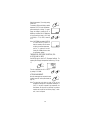
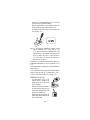
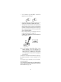
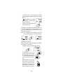
1
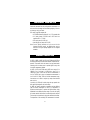
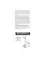
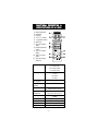
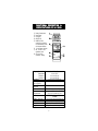
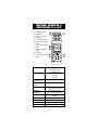
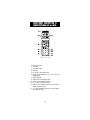
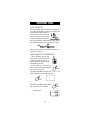
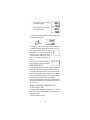
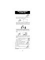
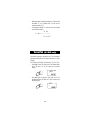
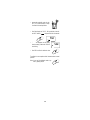
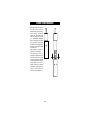
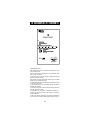
Instruction Manual
HI 9033 - HI 9034
HI 9039 - HI 9130
HI 933100 - HI 9635
Portable Waterproof
Multi-Range
Conductivity/TDS/
Fertilizer Meters
ins rum
ns
mS
COND
UCTIV
ITY
°C
HI 9331
MICRO 00
PROC
ESSOR
COND
UCTIVI
TY MET
ER
ON/OFF
CAL
CFM
FACTO
R
Manufacturers
since
UP
1978
BUF
DOWN
These Instruments are in
Compliance with the CE Directives
Dear Customer,
Thank you for choosing a Hanna Product. Please read this instruction
manual carefully before using the instrument. It will provide you with
the necessary information for a correct use of the instrument, as well
as a precise idea of its versatility. If you require further technical
information, do not hesitate to e-mail us at [email protected].
These instruments are in compliance with the directives EN 50081-1
and EN 50082-1.
TABLE OF CONTENTS
PRELIMINARY EXAMINATION ........................................................ 3
GENERAL DESCRIPTION ................................................................ 3
FUNCTIONAL DESCRIPTION OF HI 76302W CONDUCTIVITY PROBE .... 4
FUNCTIONAL DESCRIPTION & SPECIFICATIONS OF HI 9033 .......... 5
FUNCTIONAL DESCRIPTION & SPECIFICATIONS OF HI 9034 .......... 6
FUNCTIONAL DESCRIPTION & SPECIFICATIONS OF HI 9039 .......... 7
FUNCTIONAL DESCRIPTION & SPECIFICATIONS OF HI 9130 .......... 8
FUNCTIONAL DESCRIPTION & SPECIFICATIONS OF HI 933100 ...... 9
FUNCTIONAL DESCRIPTION & SPECIFICATIONS OF HI 9635 ........ 10
OPERATIONAL GUIDE ................................................................. 12
CONDUCTIVITY/TDS CALIBRATION ............................................... 15
CONDUCTIVITY VERSUS TEMPERATURE CHART ............................. 22
TDS VERSUS TEMPERATURE CHART ............................................. 23
FERTILIZER CALIBRATION (HI 9039 only) .................................... 24
TEMPERATURE COEFFICIENT (HI 933100 and HI 9635 only) ....... 25
TDS FACTOR (HI 9635 only) ...................................................... 26
TEMPERATURE CALIBRATION
(HI 9039, HI 933100 and HI 9635 only) ................................. 27
LCD SYMBOLS GUIDE ................................................................. 29
PROBE MAINTENANCE ................................................................ 30
BATTERY REPLACEMENT .............................................................. 31
ACCESSORIES ............................................................................. 32
WARRANTY ................................................................................ 33
CE DECLARATION OF CONFORMITY .............................................. 34
PRELIMINARY EXAMINATION
Remove the instrument from the packing material and examine it to
make sure that no damage has occurred during shipping. If there is
any damage, notify your Dealer.
Each meter is supplied complete with:
• HI 76302W Conductivity Probe with 1 m (3.3') screened cable
• 9 V battery (except HI 933100 and HI 9635 which are
supplied with 4 x 1.5V AA)
• Soft carrying case (HI 9130 only)
• Hard carrying case (except for HI 9130)
Note: Save all packing materials until you are sure that the
instrument functions correctly. Any defective item must be
returned in the original package together with the supplied
accessories.
GENERAL DESCRIPTION
HI 9033, HI 9034, HI 9039, HI 9130, HI 933100 and HI 9635 are
multirange conductivity/TDS meters with Automatic Temperature Compensation. These meters utilize the latest in four-ring potentiometric
technology which has been proven to provide higher accuracy than
the common amperometric method.
HI 9033, HI 9130, HI 933100 and HI 9635 have a range of 0 to
199900 µS/cm (µmho/cm); HI 9034 has a range of 0 to
19990 mg/L (ppm). HI 9635 can also take TDS measurements in
the 0 to 100,000 mg/L range, and temperature measurements in
the 0.0 to 60.0°C range. Thanks to this wide measurement range,
these meters can be used to analyze any sample from deionized
water to brine.
In particular, HI 9130 with its white casing and easy operation has
been specifically designed for the food industry.
HI 9039 can measure conductivity, temperature and two different
types of fertilizer concentrations (F1 and F2) for applications in
agriculture and horticulture. To measure the fertilizer content, simply
standardize the two different fertilizer ranges. To monitor the quality
of the water used with the fertilizer, the conductivity must be checked.
This also helps in the selection of water to be mixed with the fertilizer.
The temperature of all conductivity/TDS measurements is automati3
cally compensated for by the ATC circuitry of the meters. The stainless
steel rings of the probe have a large surface for better response and
easy cleaning. The detachable probe can be changed without
returning the unit to the factory. The probe cable is screened and 1
m (3.3') long.
The meters are constructed with a waterproof, rugged housing to
provide the versatility required for both laboratory and field use.
Another feature of the meters is the Battery Error Preventive System
(BEPS) which prevents erroneous readings due to low battery voltage.
Moreover, HI 9039, HI 933100 and HI 9635 are equipped with a
large LCD that helps the user through operation and calibration with
large comprehensive symbols. Besides displaying the selected range,
the LCD simultaneously displays the temperature. These meters are
microprocessor-based and perform buffer recognition and calibration
automatically.
For continuous monitoring HI 933100 and HI 9635 are supplied with
built-in 12VDC sockets protected behind a waterproof cover.
The temperature coefficient of HI 933100 and HI 9635 is userselectable from 0.0 to 3.0%. The TDS/conductivity ratio (factor) of
HI 9635 can be set to 0.7 (F1) or 0.5 (F2).
FUNCTIONAL DESCRIPTION OF
HI 76302W CONDUCTIVITY PROBE
1) Watertight Shielded
Screened Cable
2) 4 Stainless Steel Rings
3) Air-Release holes
4) PVC Protective Sleeve
1
3
2
4
4
FUNCTIONAL DESCRIPTION &
SPECIFICATIONS OF HI 9033
1)
2)
3)
4)
5)
6)
7)
8)
9)
10)
11)
Battery Compartment
Probe Socket
LCD Display
"mS" or "µS" Indicator
'V' Low Battery Indicator
ON/OFF Key
19.99 mS/cm Range
Selector
Conductivity Calibration
Trimmer
199.9 µS/cm Range
Selector
1999 µS/cm Range
Selector
199.9 mS/cm Range
Selector key
Range
Resolution
Accuracy
(@20°C/68°F)
Typical EMC
Deviation
Calibration
Temperature
Compensation
Probe
Battery Type/Life
Environment
Dimensions
Weight
0.0 to 199.9 µS/cm
0 to 1999 µS/cm
0.00 to 19.99 mS/cm
0.0 to 199.9 mS/cm
0.1 µS/cm
1 µS/cm
0.01 mS/cm
0.1 mS/cm
±1% Full Scale, excluding probe error
±1% Full Scale
Manual single point
through trimmer on the case
Automatic from 10 to 40°C
(50 to 104°F) with ß of 2% °C
HI 76302W with 1 m (3.3') cable
(included)
1 x 9V; 100 hours of continuous use
0 to 50°C (32 to 122°F); 100% RH
196 x 80 x 60 mm (7.7 x 3.1 x 2.4")
425 g (15 oz.); Kit: 1.4 kg (3.1 lb.)
5
FUNCTIONAL DESCRIPTION &
SPECIFICATIONS OF HI 9034
1)
2)
3)
4)
5)
6)
7)
8)
Battery Compartment
Probe Socket
LCD Display
'V' Low Battery Indicator
ON/OFF Key
19.99 g/L Range Selector
TDS Calibration Trimmer
1999 mg/L Range
Selector
9) 199.9 mg/L Range
Selector
Range
Resolution
Accuracy
(@20°C/68°F)
Typical EMC
Deviation
Calibration
Temperature
Compensation
Probe
Battery Type/Life
Environment
Dimensions
Weight
0.0 to 199.9 mg/L
0 to 1999 mg/L
0.00 to 19.99 g/L
0.1 mg/L
1 mg/L
0.01 g/L
±1% Full Scale, excluding probe error
±1% Full Scale
Manual single point
through trimmer on the case
Automatic from 10 to 50°C
(50 to 122°F) with ß of 2% °C
HI 76302W with 1 m (3.3') cable
(included)
1 x 9V; 100 hours of continuous use
0 to 50°C (32 to 122°F); 100% RH
196 x 80 x 60 mm (7.7 x 3.1 x 2.4")
425 g (15 oz.); Kit: 1.4 kg (3.1 lb.)
6
FUNCTIONAL DESCRIPTION &
SPECIFICATIONS OF HI 9039
1)
2)
3)
4)
5)
Battery Compartment
Probe Socket
LCD Display
ON/OFF Key
RANGE, to select
conductivity or temperature measurement mode
or first/second fertilizer
6) 'V' Low Battery Indicator
7) CAL, to enter or exit
calibration mode
8) CFM, to confirm
calibration reading
1
2
3
6
mS
V
CONDUCTIVITY
°C
AGRICARE
4
5
HI 9039
Microprocessor
Conductivity
Fertilizer meter
7
ON/OFF
8
RANGE
CAL
CFM
Conductivity
0 to 9999 µS/cm
Temperature
0.0 to 50.0°C
Fertilizer 1
0.00 to 9.99 g/L
Fertilizer 2
0.00 to 9.99 g/L
Resolution
1 µS/cm; 0.1°C; 0.01 g/L
Accuracy
±1% Full Scale, excluding probe error
(@20°C/68°F)
Typical EMC
±1% Full Scale
Deviation
Calibration
Automatic, single point at 5000 µS/cm
Temperature
Automatic from 10 to 50°C
Compensation
(50 to 122°F) with ß of 2% °C
Probe
HI 76302W with 1 m (3.3') cable
(included)
Battery Type/Life
1 x 9V; 100 hours of continuous use
Environment
0 to 50°C (32 to 122°F); 100% RH
Dimensions
196 x 80 x 60 mm (7.7 x 3.1 x 2.4")
Weight
425 g (15 oz.); Kit: 1.4 kg (3.1 lb.)
Range
7
FUNCTIONAL DESCRIPTION &
SPECIFICATIONS OF HI 9130
1)
2)
3)
4)
5)
6)
7)
8)
9)
10)
Battery Compartment
Probe Socket
"mS" or "µS" Indicator
LCD Display
'V' Low Battery Indicator
0 to 1999 µS/cm Range
Selector
0 to 19.99 mS/cm Range
Selector
Conductivity Calibration
Trimmer
ON/OFF Key
0 to 199.9 mS/cm Range
Selector
Range
Resolution
Accuracy
(@20°C/68°F)
Typical EMC
Deviation
Calibration
Temperature
Compensation
Probe
Battery Type/Life
Environment
Dimensions
Weight
0 to 1,999 µS/cm
0.00 to 19.99 mS/cm
0.0 to 199.9 mS/cm
1 µS/cm
0.01 mS/cm
0.1 mS/cm
±2% Full Scale, excluding probe error
±1% Full Scale
Manual single point
through trimmer on the case
Automatic from 10 to 40°C
(50 to 104°F) with ß of 2%/°C
HI 76302W with 1 m (3.3') cable
(included)
1 x 9V; 100 hours of continuous use
0 to 50°C (32 to 122°F); 100% RH
196 x 80 x 60 mm (7.7 x 3.1 x 2.4")
425 g (15 oz.); Kit: 1.4 kg (3.1 lb.)
8
FUNCTIONAL DESCRIPTION &
SPECIFICATIONS OF HI 933100
1)
2)
3)
4)
5)
Battery Compartment
Probe Socket
Liquid Crystal Display
7
2
ON/OFF Key
CAL, to enter or exit calibration mode
6) FACTOR, to set the temperature coefficient or select 3
8
the temperature mode
7) 12VDC Power Socket
9
8) 'LOBAT' Low Battery
4
9) CFM, to confirm the cali- 5
10
bration reading
11
10) BUF, to select the calibra- 6
12
tion buffer value
11) DOWN, to set the temperature coefficient or for manual temperature compensation setting
12) UP, to set the temperature coefficient or for manual temperature compensation setting
Range Conductivity
0.0 to 150.0 µS/cm
150 to 1500 µS/cm
1.50 to 15.00 mS/cm
15.0 to 199.9 mS/cm
Temperature
0.0 to 60.0°C
Resolution
0.1 µS/cm; 1 µS/cm; 0.01 mS/cm;
0.1 mS/cm; 0.1°C
Accuracy
±1% Full Scale; ±0.5°C
(@20°C/68°F)
excluding probe error
Typical EMC
±1% Full Scale
Deviation
±0.2 °C
Calibration
Automatic, two points
at 0 and 1413 or 12880 µS/cm
Temperature
Automatic or manual from 10 to 60°C
Compensation
(50 to 140°F) with ß from 0 to 3%/°C
Probe
HI 76302W with 1 m (3.3') cable
(included)
Battery Type/Life
4 x 1.5V AA; 150 hours of
continuous use. Power socket for 12VDC
Environment
0 to 50°C (32 to 122°F); 100% RH
Dimensions
196 x 80 x 60 mm (7.7 x 3.1 x 2.2")
Weight
425 g (15 oz.); Kit: 1.4 kg (3.1 lb.)
1
ins rum n s
mS
CONDUCTIVITY
LO BAT
°C
HI 933100
MICROPROCESSOR
CONDUCTIVITY METER
ON/OFF
9
CAL
CFM
BUF
FACTOR
UP
DOWN
FUNCTIONAL DESCRIPTION &
SPECIFICATIONS OF HI 9635
1)
2)
3)
4)
5)
6)
7)
8)
9)
10)
11)
12)
Battery Compartment
Probe Socket
Liquid Crystal Display
ON/OFF Key
CAL, to enter or exit calibration mode
FACTOR, to show temperature, %TC or TDS factor on the
secondary display
12VDC Power Socket
RANGE, to select the measurement mode
CFM, to confirm the calibration reading
BUF, to select the calibration buffer value
DOWN, to set the temperature coefficient or for manual temperature compensation setting
UP, to set the temperature coefficient or for manual temperature compensation setting
10
RANGE
Conductivity
TDS
Temperature
Resolution
Cond.
TDS
Temperature
Cond.
(@20°C/68°F)
TDS
Temperature
Accuracy
Typical EMC Cond.
Deviation
TDS
Temperature
Calibration
Temperature
Compensation
Probe
Battery Type/Life
Environment
Dimensions
Weight
0.0 to 150.0 µS/cm
150 to 1500 µS/cm
1.50 to 15.00 mS/cm
15.0 to 199.9 mS/cm
0.0 to 150.0 mg/L (ppm)
150 to 1500 mg/L (ppm)
1.50 to 15.00 g/L (ppt)
15.0 to 100.0 g/L (ppt)
0.0 to 60.0°C
0.1 µS/cm / 1 µS/cm
0.01 mS/cm / 0.1 mS/cm
0.1 mg/L (ppm) / 1 mg/L (ppm)
0.01 g/L (ppt) / 0.1 g/L (ppt)
0.1°C
±2% Full Scale
±2% Full Scale
±0.5°C
excluding probe error
±2% Full Scale
±2% Full Scale
±0.5°C
Automatic 1, 2 or 3 point calibration
at 84, 1413 or 12880 µS/cm
Automatic or manual from 0 to 60°C
(32 to 140°F) with adjustable ß
from 0.0 to 3.0% /°C and
TDS factor at 0.70 or 0.50.
Compensation referenced to 25°C (77°F)
HI 76302W with 1 m (3.3') cable
(included)
4x1.5V AA/150 hours of continuous use
Auto-shut off after 10' of non use
12VDC power socket
0 to 50°C (32 to 122°F); 100% RH
196 x 80 x 60 mm (7.7 x 3.1 x 2.4")
425 g (15 oz.); Kit: 1.4 kg (3.1 lb.)
11
OPERATIONAL GUIDE
INITIAL PREPARATION
Each meter is supplied complete with battery(ies). Remove the back
cover, unwrap the battery(ies) and install it (them) while paying
attention to polarity its (their) (see page 31).
Connect the probe to the meter securely by
aligning the pins with the socket, pushing
the plug in and tightening the threaded ring.
Make sure that the sleeve is properly inserted on the probe, with the
holes towards the top of the probe (the end nearest to the cable).
Make sure that the meter has been calibrated before taking any
measurements (see page 15).
TAKING CONDUCTIVITY/TDS MEASUREMENTS
To take a measurement, place the probe
into the solution to be tested with the holes
completely submerged. Tap and stir the
probe to remove all air bubbles that may be
trapped inside the PVC sleeve.
Turn the instrument on by first pressing the
ON/OFF key and then selecting the desired range
ON/OFF
(not HI 933100 and HI 9635).
With HI 9039, press RANGE to choose the range. "F1" and "F2" will
appear to show the first or the second fertilizer range.
RANGE
F1
With HI 9635, press RANGE to select the desired
mode, which can be one of the following:
RANGE
• Conductivity mode
µS
CONDUCTIVITY
°C
12
• TDS1 mode: TDS with 0.7 factor (shown
on the secondary display)
ppm
• TDS2 mode: TDS with 0.5 factor (shown
on the secondary display)
ppm
In the TDS mode, by pressing FACTOR the secondary display shows
the temperature of the solution .
ppm
°C
FACTOR
F1
HI 933100 and HI 9635 are auto-ranging conductivity meters, and
the reading automatically switches from one resolution to the next.
With HI 9033, HI 9034 and HI 9130, if the
LCD displays a "1" on the far left hand side,
the meter is out of range and the solution
measured exceeds the selected range. In this
case, the next (higher) range should be selected.
With HI 9039, HI 933100 and HI 9635 the
out of range prompt is given by four hyphens.
TEMPERATURE EFFECT
HI 76302W conductivity probe has a built-in temperature sensor and
automatically compensates for any temperature differences. Wait for a
few minutes for the temperature sensor to attain thermal equilibrium
with the test solution before taking the measurement. If the temperature of the conductivity probe and the solution is drastically different,
a longer time should be allowed before taking readings.
Once the reading stabilizes, the measurement is complete. If further
measurements are desired, rinse the probe with tap water and test
the next sample.
MANUAL TEMPERATURE COMPENSATION (FOR
HI 933100 AND HI 9635)
To perform manual temperature compensation, use HI 933100
and HI 9635 with HI 76301W conductivity probe instead of the
supplied HI 76302W.
Connect HI 76301W to the meter.
13
Select the temperature (°C) mode by pressing
FACTOR once.
The secondary LCD figure will display a default
temperature of 25°C or the last recorded temperature reading with a blinking "°C" symbol.
Change the reading by pressing the UP or
DOWN keys. Hold down the UP or DOWN keys
to force the reading to change in 0.5°C steps
(HI 933100) or 1°C (HI 9635) instead of
0.1°C.
Note: If HI 76302W is connected to HI 933100
or HI 9635 and the °C mode is selected, the secondary LCD will continue
to display the measured temperature ,
and the "°C" symbol will not blink.
Pressing UP or DOWN will also not alter
the temperature readings.
FACTOR
°C
UP
DOWN
°C
TEMPERATURE COEFFICIENT SELECTION (FOR
HI 933100 AND HI 9635)
Press FACTOR again to select the TC (Temperature Coefficient). The
secondary LCD will display the temperature coefficient (e.g. 2.0% per
°C).
FACTOR
This value is adjustable from 0.0 to 3.0%/°C
by pressing UP or DOWN.
UP
DOWN
AFTER MEASUREMENTS
When all measurements are completed the meter
should be turned OFF and the probe cleaned (see
ON/OFF
page 30).
Note: The probe body and sleeve are made of PVC and are
susceptible to damage due to temperatures exceeding 60°C
(140°F). If the probe is exposed to high temperature, the
bond between the rings and the probe body may become
impaired and the probe will not function properly, in which
case, it has to be replaced.
14
CONDUCTIVITY/TDS CALIBRATION
For best results in calibrating your meter, choose a conductivity/TDS
solution that is closest in value to the sample to be measured.
For example if your measurements are in the 2 to 20 mS/cm range,
ideally use the HI 7030 or HI 8030 (12880 µS/cm=12.88 mS/cm)
conductivity calibration solution.
For accurate calibration, use
RINSE
CALIBRATION
two beakers for each solution:
the first one for rinsing the
probe and the second one for
calibration. In this way, contamination of the calibration solutions is
minimized.
In order to minimize any EMC interference, use plastic beakers for the
solutions, wherever possible.
A complete list of the Hanna calibration solutions is given in the
Accessories section (page 32).
PROCEDURE FOR HI 9033 AND HI 9130
• Fill a beaker with 8 cm (3¼") of conductivity calibration solution (if possible fill
two beakers and use one as rinse and
the other for calibration).
• Make sure that the probe is connected to
the meter securely by aligning the pins
with the socket, pushing the plug in
and tightening the threaded ring.
• Immerse the probe into the beaker. The
level of solution must be higher than the
holes on the PVC sleeve.
• Turn the instrument on by pressing the ON/OFF key and select
the appropriate range (e.g. 19.99 mS/cm).
ON/OFF
19.99mS/cm
• Tap the probe repeatedly on the bottom of the beaker and stir it
to ensure that no air bubbles are trapped inside the sleeve.
• If the temperature of the probe is close to that of the solution, the
display will stabilize quickly and provide you with temperature
compensated conductivity measurements. However, allow a few
15
minutes if there is a temperature difference of 5°C (9°F) or more
for the ATC circuitry to compensate completely.
• When the reading stabilizes, turn the calibration trimmer until
the display reads the proper conductivity value @25°C.
For example with HI 7030/HI 8030 turn the trimmer to read
12.88 mS/cm @ 25°C.
mS
Note: It is also possible to standardize the calibration to have
readings compensated to 20°C (68°F) rather than 25°C
(77°F). During the calibration, as explained above, simply
adjust the trimmer to the calibration buffer reading at 20°C
(68°F). For example, for HI 7030 / HI 8030 this value is
11.67 mS/cm and can be found on the conductivity vs.
temperature chart on page 22.
The calibration is now complete and the instrument is ready for use.
All subsequent measurements will now be compensated to 25°C
(77°F).
If the instrument cannot be calibrated refer to the Probe Maintenance
section (page 30).
You can calibrate the instrument using any other Hanna calibration
solution in exactly the same way. For example with HI 7031 /
HI 8031 turn the trimmer to obtain 1413 µS/cm @25°C.
PROCEDURE FOR HI 9034
• Fill a beaker with 8 cm (3¼") of TDS
calibration solution (if possible fill two
beakers and use one as rinse and the
other for calibration).
• Make sure that the probe is connected to
the meter securely by aligning the pins
with the socket, pushing the plug in and
tightening the threaded ring.
• Immerse the probe into the beaker. The
level of solution must be higher than the
holes on the PVC sleeve.
16
• Turn the instrument on by pressing ON/OFF and select the
appropriate range (e.g. 1999 mg/L).
ON/OFF
1999mg/l
• Tap the probe repeatedly on the bottom of the beaker and stir it
to ensure that no air bubbles are trapped inside the sleeve.
• If the temperature of the probe is close to that of the solution, the
display will stabilize quickly and provide you with temperature
compensated TDS measurements. However, allow a few minutes if
there is a temperature difference of 5°C (9°F) or more for the ATC
circuitry to compensate completely.
• When the reading stabilizes, turn the calibration trimmer until
the display reads the proper TDS value @25°C.
For example, when calibrating with HI 7032 turn the trimmer to
read 1382 mg/L @25°C.
Note: It is also possible to standardize the calibration to have
readings compensated to 20°C (68°F) rather than 25°C
(77°F). Simply adjust the trimmer to the calibration buffer
reading at 20°C (68°F). For example, for HI 7032 this value
is 1251 mg/L and can be found on the TDS vs. temperature
chart on page 23.
The calibration is now complete and the instrument is ready for use.
All subsequent measurements will now be compensated to 25°C
(77°F).
If the instrument cannot be calibrated, refer to the Probe Maintenance section (page 30).
You can calibrate the instrument using any other Hanna calibration
solution in exactly the same way. For example with HI 7038 turn the
trimmer to obtain 6.44 g/L @25°C.
17
PROCEDURE FOR HI 9039
• Fill a beaker with 8 cm (3¼") of HI 7039
or HI 8039 conductivity calibration solution at 5000 µS/cm @25°C (if possible
fill two beakers and use one as rinse and
the other for calibration).
• Make sure that the probe is connected to
the meter securely by aligning the pins
with the socket, pushing the plug in and
tightening the threaded ring.
• Immerse the probe into the beaker. The
level of solution must be higher than the
holes on the PVC sleeve.
• Turn the instrument on by pressing ON/OFF and select the
conductivity measurement mode by pressing RANGE.
RANGE
ON/OFF
• Tap the probe repeatedly on the bottom of the beaker and stir it
to ensure that no air bubbles are trapped inside the sleeve.
• Press CAL to display "5000 µS" together with the "CAL" symbol
and an intermittent "BUF" indicator.
µS
°C
CAL
CAL
BUF
• If the reading is within 15% of the theoretical value, the meter
automatically recognizes the standard solution and the "BUF"
symbol will stop flashing.
•"
" will disappear from the display
when the reading is stable and the CON
"CON" symbol will start blinking.
• Press CFM to confirm the calibration reading.
Calibration is now complete and the instrument is
CFM
ready for use. All subsequent measurements will
now be compensated to 25°C (77°F). If the
instrument cannot be calibrated refer to the
Probe Maintenance section (page 30).
Press CAL to quit the calibration mode.
µS
°C
CAL
18
PROCEDURE FOR HI 933100
• Make sure that the conductivity probe is
connected to the meter securely by aligning the pins with the socket, pushing the
plug in and tightening the threaded
ring.
• Dry the probe and leave it in the air.
ON/OFF
• Turn the instrument on by pressing ON/OFF.
• Press CAL to display "0.0 µS" together with the "CAL" symbol and
an intermittent "BUF" indicator.
CAL
• "
" will disappear from the display
when the reading is stable and the "CON"
symbol will start blinking.
• Press CFM to confirm the calibration value
and exit the calibration mode.
CFM
• Fill a beaker with 8 cm (3¼") of
HI 7031/HI 8031, at 1413 µS/cm
@25°C, or HI 7030/HI 8030, at
12880 µS/cm @25°C (if possible fill
two beakers and use one as rinse and
the other for calibration).
• Immerse the probe into the beaker. The
level of solution must be higher than the
holes on the PVC sleeve.
• Tap the probe gently on the bottom of the beaker and stir it to
ensure that no air bubbles are trapped inside the sleeve.
• Press CAL to display "1413 µS" together with the "CAL" symbol
and an intermittent "BUF" indicator.
µS
°C
CAL
CAL
BUF
• Press BUF if you are calibrating with HI 7030/
HI 8030 to display "12.88mS" instead of
"1413 µS".
19
BUF
• If the reading is within 15% of the theoretical value, the meter
automatically recognizes the buffer and the "BUF" symbol will stop
flashing.
• "
" will disappear from the display
when the reading is stable and "CON" CON
symbol will start blinking.
• Press CFM to confirm the calibration value and
quit the calibration mode.
µS
°C
CFM
The calibration is now complete and the instrument is ready for use.
All subsequent measurements will now be compensated to 25°C
(77°F). If the instrument cannot be calibrated refer to the Probe
Maintenance section (page 30).
Note: In order to calibrate with a first calibration value other than
0 µS/cm, press BUF to select 1413 µS/cm or 12.88 mS/cm.
µS
°C
BUF
CAL
BUF
PROCEDURE FOR HI 9635
Before proceeding with the conductivity calibration, set the temperature coefficient to 2% (see page 25).
• Press RANGE to select the conductivity measurement mode.
µS
CONDUCTIVITY
°C
RANGE
• Fill a beaker with 8 cm (3¼") of
HI 7033/HI 8033 conductivity calibration solution at 84.0 µS/cm @25°C/
77°F (if possible fill two beakers and use
one as rinse and the other for calibration).
• Immerse the probe into the beaker. The
level of solution must be higher than
the holes on the PVC sleeve. Tap the
probe repeatedly on the bottom of the
beaker and stir it to ensure that no air
bubbles are trapped inside the sleeve.
20
8 cm
(3¼)
• Press CAL to display "84.0µS" together with the "CAL" symbol
and an intermittent "BUF" indicator.
µS
°C
CAL
CAL
BUF
• If the reading is within 15% of the theoretical value, then the
meter automatically recognizes the value.
• "
" will disappear from the display
when the reading is stable and "CON" will
CON
start blinking.
• Press CFM to confirm the calibration value and the display will
show "1413µS" expecting the 2nd calibration solution.
µS
°C
µS
°C
CAL
CFM
BUF
• Repeat the same procedure using HI 7031/HI 8031 conductivity
calibration solution at 1413 µS/cm @25°C/77°F.
• After confirmation of the 2nd calibration
value the display will show "1.41mS" expecting the 3rd calibration solution.
• Press BUF to select the 12.88 mS/cm calibration value.
mS
°C
BUF
CAL
BUF
• Repeat the same procedure using HI 7030/HI 8030 conductivity
calibration solution at 12.88 mS/cm @25°C/77°F.
• After confirmation of the 3rd calibration solution, if everything is
satisfactory, the calibration ends and the meter returns to the
normal operational mode.
Three-point calibration is now complete and the instrument is ready
for use. All subsequent measurements will now be compensated to
25°C (77°F).
Notes:
• To perform the calibration with a different first calibration value than
84 µS/cm, press BUF to select one of the other standard solutions.
• To quit after 1 or 2 point calibration, press CAL.
• If the instrument will not calibrate refer to the Probe Maintenance
and Cleaning section (page 30).
21
CONDUCTIVITY VERSUS
TEMPERATURE CHART
The conductivity of an aqueous solution is the measure of its ability to
carry an electrical current by means of ionic motion.
The conductivity invariably increases with increasing temperature.
It is affected by the type and number of ions in the solution and by
the viscosity of the solution itself. Both parameters are temperature
dependent. The dependency of conductivity on temperature is expressed as a relative change per degree Celsius at a particular
temperature, commonly as percent per °C.
°C
°F
0
5
10
15
16
17
18
19
20
21
22
23
24
25
26
27
28
29
30
31
32
41
50
59
60.8
62.6
64.4
66.2
68
69.8
71.6
73.4
75.2
77
78.8
80.6
82.4
84.2
86
87.8
HI 7030
HI 8030
HI 7031
HI 8031
HI 7033
HI 8033
HI 7034
HI 8034
HI 7035
HI 8035
(µS/cm)
(µS/cm)
7150
8220
9330
10480
10720
10950
11190
11430
11670
11910
12150
12390
12640
12880
13130
13370
13620
13870
14120
14370
776
896
1020
1147
1173
1199
1225
1251
1278
1305
1332
1359
1386
1413
1440
1467
1494
1521
1548
1575
(µS/cm)
(µS/cm)
(µS/cm)
64
65
67
68
70
71
73
74
76
78
79
81
82
84
86
87
89
90
92
94
48300
53500
59600
65400
67200
68500
69800
71300
72400
74000
75200
76500
78300
80000
81300
83000
84900
86300
88200
90000
65400
74100
83200
92500
94400
96300
98200
100200
102100
104000
105900
107900
109800
111800
113800
115700
117700
119700
121800
123900
22
HI 7039
HI 8039
(µS/cm)
2760
3180
3615
4063
4155
4245
4337
4429
4523
4617
4711
4805
4902
5000
5096
5190
5286
5383
5479
5575
TDS VERSUS
TEMPERATURE CHART
The TDS value in aqueous solutions is directly proportional to conductivity. The ratio between the two parameters depends on the solution
and usually it is set to a factor of 0.5 (corresponding to a solution of
CaCO3). This means that 1 µS/cm is equal to 0.5 mg/L (ppm) of TDS.
With HI 9635, the TDS factor can be set to 0.5 or 0.7 depending on
the solution to be measured (see page 26). For accurate TDS
measurements, make sure that HI 9635 has been calibrated in a
conductivity standard solution and the temperature coefficient is
properly set.
°C
°F
HI 7032
mg/L
(ppm)
HI 7036
g/L
(ppt)
0
5
10
15
16
17
18
19
20
21
22
23
24
25
26
27
28
29
30
31
32
41
50
59
60.8
62.6
64.4
66.2
68
69.8
71.6
73.4
75.2
77
78.8
80.6
82.4
84.2
86
87.8
758
876
999
1122
1148
1173
1200
1224
1251
1277
1303
1329
1358
1382
1408
1438
1461
1476
1515
1541
6.82
7.88
8.99
10.10
10.33
10.56
10.78
11.01
11.24
11.47
11.71
11.94
12.18
12.41
12.65
12.89
13.13
13.37
13.61
13.85
23
FERTILIZER CALIBRATION
( HI 9039 only )
• Turn the HI 9039 on by pressing ON/OFF.
ON/OFF
• Select the first fertilizer range (F1) by pressing RANGE. "F1"
symbol will appear on the secondary display
RANGE
F1
Fe
rtiliz
er
• Dissolve 1 gram of your fertilizer in 1 liter of distilled water and
immerse the probe into the solution (1.00 g/L @25°C). The
level of solution must be higher than the holes on the PVC sleeve.
• Tap the probe repeatedly on the bottom of the beaker and stir it
to ensure that no air bubbles are trapped inside the sleeve.
• Press CAL to display "1.00 g" together with the "CAL" and "BUF"
symbols.
gm
°C
CAL
CAL
BUF
F1
• If the buffer is within the theoretical range, then the meter
automatically recognizes the buffer and the "BUF" symbol stops
flashing.
• "
" will disappear from the display
when the reading is stable and "CON"
symbol will start blinking.
• Press CFM to confirm the calibration value.
The calibration is now complete and the instruCFM
ment is ready to measure fertilizer content.
If the instrument cannot be calibrated refer to the Probe Maintenance
section (page 30).
To quit the calibration mode, press CAL at any
time.
CAL
Repeat the same procedure for the second fertilizer, i.e. F2, by
pressing RANGE.
gm
CON
°C
F1
24
TEMPERATURE COEFFICIENT
(HI 933100 and HI 9635 only
only))
SETTING THE TEMPERATURE COEFFICIENT
• Switch the meter on by pressing ON/OFF.
ON/OFF
• Press FACTOR until the temperature coefficient is displayed.
µS
CONDUCTIVITY
FACTOR
%TC
• Change this value by pressing UP or
DOWN. This value is adjustable from 0.0
to 3.0% per degree Celsius.
This feature is particularly helpful with acids, alkalis and concentrated
salt solutions which typycally have lower values, around 1.5%/°C.
All readings the readings are standardized at 25°C.
The default temperature coefficient is 1.9%. The coefficient can be set
from 0.0% (without compensation) to 3.0% per degree Celsius. The
meter retains this coefficient even when switched off.
UP
DOWN
DETERMINATION OF THE TEMPERATURE COEFFICIENT
OF A SOLUTION
• Immerse the probe into the solution and press RANGE if necessary
to select conductivity measurements.
RANGE
• Press FACTOR to display the temperature
coefficient.
FACTOR
• Set the temperature coefficient to "0.0%" (i.e. no compensation)
by pressing DOWN.
µS
CONDUCTIVITY
DOWN
%TC
• Measure the conductivity of the sample at 25°C and denote it as
"C25".
25
• Measure the sample at a different temperature "t°C" which should
be between 5°C to 10°C different from 25°C and note the
conductivity reading as "Ct".
• The temperature coefficient "ß" of the solution can be calculated
with the following formula:
(Ct - C25)
ß = 100 x --------------------------(t°C - 25) x C25
TDS FACTOR (HI 9635 only
only))
Some solutions, especially in horticulture, use 0.7 as the conversion
rate between conductivity and TDS instead of the common 0.5 CaCO3
TDS factor.
The TDS factor of HI 9635 can be selected as 0.7 (F1) or 0.5 (F2).
• Press RANGE to enter TDS1 mode, that is Total Dissolved Solids
with a TDS factor of 0.7 (F0.70 is shown on the secondary
display).
1.95
gppm
m
TDS
RANGE
• Press RANGE again to change to TDS2 mode, that is Total
Dissolved Solids with a TDS factor of 0.5 (F0.50 is shown on the
secondary display).
1.39
TDS
RANGE
26
gm
ppm
TEMPERATURE CALIBRATION
(HI 9039, HI 933100 and HI 9635 only
only))
INITIAL PREPARATION
Prepare a container of ice and water and another container with hot
water at a temperature of 50°C. Place insulation material around the
containers to minimize temperature changes.
Use a CHECKTEMPC or a calibrated thermometer with a resolution of
0.1 as reference thermometer.
°C
°C
50 °C
(122 °F)
0 °C
(32 °F)
Note: After temperature calibration, recalibrate the instrument (for
conductivity or fertilizer content).
• Press CAL and ON/OFF simultaneously.
ON/OFF
RANGE
CAL
°C
• Immerse the conductivity probe into the
0°C (32°F) bath.
0 °C
(32 °F)
• When the reading stabilizes, press CAL. "0.0°C", "CAL" symbol
"
and an intermittent "BUF" indicator will be displayed. "
symbol will blink for a few seconds.
°C
CAL
CAL
BUF
• "
" symbol will disappear from the
display when the reading is stable and
"CON" will start blinking.
°C
CON
• Press CFM to confirm the calibration value.
CFM
27
°C
• Immerse the conductivity probe into the
50°C (122°F) bath and wait for a couple
of minutes for thermal equilibrium.
50 °C
(122 °F)
• Press CAL to display the "50.0°C", "CAL" symbol and an intermit" will symbol blink for a few seconds.
tent "BUF" indicator. "
°C
CAL
CAL
BUF
• "
" will disappear from the display
when the reading is stable and "CON" will
start blinking.
°C
CON
• Press CFM to confirm the calibration value.
CFM
The calibration is now complete and the instrument returns to normal
operation.
Note: You can quit the calibration mode at any
time by pressing ON/OFF.
ON/OFF
28
LCD SYMBOLS GUIDE
µS
Measurement in µS/cm (except HI 9034)
mS
Measurement in mS/cm (except HI 9034)
For HI 9033, HI 9034 and HI 9130 only
1
Out of range
V
Low battery voltage
For HI 9039, HI 933100 and HI 9635 only
---Out of range
LOBAT
Low battery voltage
CAL
Calibration mode
CON
Ready for confirmation
(blinking)
Input reading not stable
BUF
Calibration buffer valid
BUF (blinking)
Calibration buffer not valid or not yet
recognized
CONDUCTIVITY
Conductivity measurement
°C
Automatic temperature compensation
mode
For HI 9039 only
FERTILIZER
Fertilizer measurement
F1
1st fertilizer concentration
F2
2nd fertilizer concentration
°C (blinking)
Temperature out of range
For HI 933100 and HI 9635 only
%TC
Temperature coefficient mode
°C (blinking)
Manual temperature compensation mode
For HI 9635 only
TDS
TDS measurement
ppm
TDS Measurement in mg/L (ppm)
gm
TDS Measurement in g/L (ppt)
F0.70 or F1
0.7 as TDS factor
F0.50 or F2
0.5 as TDS factor
29
PROBE MAINTENANCE
Rinse the probe with tap water after every series of
measurements. If a more thorough cleaning is required,
remove the PVC sleeve and
clean the probe with a cloth
or a nonabrasive detergent.
When reinserting the sleeve
onto the probe, be sure that
the sleeve is in the right direction with the four holes towards
the cable end.
After cleaning the probe, recalibrate the instrument.
The probe body is PVC. For
this reason it must never come
into close contact with a heat
source. If the probe is exposed
to high temperatures, the rings
might become loose or detached, resulting in a serious
impairment of the probe functioning. In such cases, the
probe has to be replaced.
30
BATTERY REPLACEMENT
The meters are supplied with the advanced
"BEPS" technology. BEPS, or Battery Error
Preventive System, will detect a low power V
condition in the battery and display "V"
(HI 9033, HI 9034 and HI 9130) or
"LO BAT" (HI 9039, HI 933100 and
HI 9635) on the LCD.
This is to alert the user that the display will
shut-off after approximately 5 more hours of
use if batteries are not repalced.
BEPS shuts off the display completely to prevent erroneous measurements being taken.
Battery replacement must only take place in
a non-hazardous area using the battery
types specified in this instruction manual.
In order to replace rundown batteries, simply remove the two screws on the rear cover
of the instrument and replace the four
1.5V AA batteries (HI 933100 and HI 9635)
or the 9V Alkaline battery (HI 9033, HI
9034, HI 9039, HI 9130) with new ones,
paying attention to the correct polarity.
When the meter is turned on, BEPS will
detect the new battery and ensure that it
functions properly.
The meter should be recalibrated after every battery change.
HI 933100 and HI 9635 can also be connected to a 12VDC car
battery or external power supply by means of an adapter. In
addition both meters are equipped with auto shut-off circuitry that
will switch the meter off after approximately 10 minutes of non-use.
31
ACCESSORIES
CONDUCTIVITY & TDS CALIBRATION SOLUTIONS
HI 7030L
HI 7030M
HI 7031L
HI 7031M
HI 7033L
HI 7033M
HI 7034L
HI 7034M
HI 7035L
HI 7035M
HI 7039L
HI 7039M
HI 7032L
HI 7032M
HI 7036L
HI 7036M
12880 µS/cm (µmho/cm), 460 mL
12880 µS/cm (µmho/cm), 230 mL
1413 µS/cm (µmho/cm), 460 mL
1413 µS/cm (µmho/cm), 230 mL
84 µS/cm (µmho/cm), 460 mL
84 µS/cm (µmho/cm), 230 mL
80000 µS/cm (µmho/cm), 460 mL
80000 µS/cm (µmho/cm), 230 mL
111800 µS/cm (µmho/cm), 460 mL
111800 µS/cm (µmho/cm), 230 mL
5000 µS/cm (µmho/cm), 460 mL
5000 µS/cm (µmho/cm), 230 mL
1382 ppm (mg/L), 460 mL
1382 ppm (mg/L), 230 mL
12.41 ppt (g/L), 460 mL
12.41 ppt (g/L), 230 mL
CONDUCTIVITY & TDS CALIBRATION SOLUTIONS
IN FDA APPROVED BOTTLES
HI 8030L
HI 8031L
HI 8033L
HI 8034L
HI 8035L
HI 8039L
12880 µS/cm (µmho/cm), 460 mL
1413 µS/cm (µmho/cm), 460 mL
84 µS/cm (µmho/cm), 460 mL
80000 µS/cm (µmho/cm), 460 mL
111800 µS/cm (µmho/cm), 460 mL
5000 µS/cm (µmho/cm), 460 mL
OTHER ACCESSORIES
9V battery for HI 9033, HI 9034, HI 9039 and
HI 9130 (10 pcs)
HI 721308 1.5V AA size alkaline battery for HI 933100 and HI
9635 (10 pcs)
CHECKTEMPC Electronic thermometer (range -50.0 to 150°C)
HI 710005 Power adapter from 115VAC to 12VDC (for HI 933100
and HI 9635)
HI 710006 Power adapter from 230VAC to 12VDC (for HI 933100
and HI 9635)
HI 721310
32
Small screwdrivers, length 90 mm, for calibration
purposes (20 pcs) (for HI 9033, HI 9034 and HI 9130
only)
HI 76301W 4-ring probe without temperature sensor, for Manual
Temperature Compensation measurements with
HI 933100 and HI 9635
HI 76302W 4-ring probe with temperature sensor, for Automatic
Temperature Compensation measurements
HI 710031 Hard carrying case
MANCONWPR2 Instruction Manual
HI 731326
WARRANTY
All Hanna Instruments meters are warranted for two years
against defects in workmanship and materials when used for their
intended purpose and maintained according to instructions. The
electrodes and the probes are warranted for a period of six
months. This warranty is limited to repair or replacement free of
charge.
Damages due to accident, misuse, tampering or lack of prescribed
maintenance are not covered.
If service is required, contact the dealer from whom you purchased the
instrument. If under warranty, report the model number, date of
purchase, serial number and the nature of the failure. If the repair
is not covered by the warranty, you will be notified of the charges
incurred. If the instrument is to be returned to Hanna Instruments,
first obtain a Returned Goods Authorization number from the Customer Service department and then send it with shipping costs
prepaid. When shipping any instrument, make sure it is properly
packaged for complete protection.
To validate your warranty, fill out and return the enclosed warranty
card within 14 days from the date of purchase.
All rights are reserved. Reproduction in whole or in part is prohibited
without the written consent of the copyright owner,
Hanna Instruments Inc., 584 Park East Drive, Woonsocket, Rhode
Island, 02895 , USA.
Hanna Instruments reserves the right to modify the design, construction and appearance of its products without advance notice.
33
CE DECLARATION OF CONFORMITY
Recommendations for Users
Before using these products, make sure that they are entirely suitable for the environment in which they are used.
Operation of these instruments in residential areas could cause unacceptable interferences to radio and TV equipment.
The metal band at the end of the probe is sensitive to electrostatic discharges. Avoid
touching this metal band at all times.
During calibration of instruments, ESD wrist straps should be worn to avoid possible
damage to the probe by electrostatic discharge.
To maintain the EMC performance of this equipment the recommended cables noted in
the user's manual must be used.
Any variation introduced by the user to the supplied equipment may degrade the
instruments' EMC performance.
To avoid electrical shock, do not use these instruments when voltages at the measurement surface exceed 24VAC or 60VDC.
To avoid damages or burns, do not perform any measurement in microwave ovens.
In particular cases the meters could turn off. In such cases they can be turned on by
pressing the ON/OFF key.
In particular cases the meters, except HI 9635, could change the measurement range.
In such cases they can be reverted to the desired range by pressing the proper key.
34
OTHER PRODUCTS FROM HANNA
•
•
•
•
•
•
•
•
•
•
•
•
•
•
•
•
•
•
•
CALIBRATION AND MAINTENANCE SOLUTIONS
CHEMICAL TEST KITS
CHLORINE METERS
DISSOLVED OXYGEN METERS
HYGROMETERS
ION SPECIFIC METERS (Colorimeters)
MAGNETIC STIRRERS
Na/NaCl METERS
pH/ORP/Na ELECTRODES
pH/ORP METERS
PROBES (DO, µS/cm, RH, T, TDS)
PUMPS
REAGENTS
SOFTWARE
THERMOMETERS
TITRATORS
TRANSMITTERS
TURBIDITY METERS
Wide Range of Accessories
Most Hanna meters are available in the following formats:
• BENCH-TOP METERS
• POCKET-SIZED METERS
• PORTABLE METERS
• PRINTING/LOGGING METERS
• PROCESS METERS (Panel and Wall-mounted)
• WATERPROOF METERS
• METERS FOR FOOD INDUSTRY
For additional information, contact your dealer or the nearest Hanna
Customer Service Center. You can also e-mail us at:
[email protected].
HANNA LITERATURE
Hanna publishes a wide range of catalogs and handbooks for an equally wide range of applications.
The reference literature currently covers areas such as:
• Water Treatment
• Process
• Swimming Pools
• Agriculture
• Food
• Laboratory
• Thermometry
and many others. New reference material is constantly
being added to the library.
PRINTED IN PORTUGAL
For these and other catalogs, handbooks and leaflets,
contact your dealer or the Hanna Customer Service
Center nearest to you. To find the Hanna Office in
your vicinity, check our home page at
www.hannainst.com.
MANCONWPR3
03/00
h t t p : / / w w w . h a n n a i n s t . c o m