1
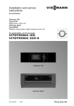
Installation and service
instructions
VIESMANN
for contractors
Vitotronic 100
Type GC1B
Digital boiler control unit
For applicability, see the last page
VITOTRONIC 100
5600 634 GB
7/2011
Please keep safe.
Safety instructions
Safety instructions
Please follow these safety instructions closely to prevent accidents and material losses.
Safety instructions explained
Danger
This symbol warns against the
risk of injury.
!
Please note
This symbol warns against the
risk of material losses and environmental pollution.
Note
Details identified by the word "Note" contain additional information.
■ all current safety regulations as
defined by DIN, EN, DVGW, TRGI,
TRF, VDE and all locally applicable
standards,
■ Gas Safety (Installation & Use) Regulations
– the appropriate Building Regulation
either the Building regulations, the
Building Regulation (Scotland),
Building Regulations (Northern Ireland),
– the Water Fittings Regulation or
Water Bylaws in Scotland,
– the current I.E.E. Wiring Regulations.
Target group
If you smell gas
Regulations
Observe the following when working on
this system
■ all legal instructions regarding the prevention of accidents,
■ all legal instructions regarding environmental protection,
■ the Code of Practice of relevant trade
associations,
2
Danger
Escaping gas can lead to explosions which may result in serious
injury.
■ Never smoke. Prevent naked
flames and sparks. Never
switch lights or electrical appliances ON or OFF.
■ Close the gas shut-off valve.
■ Open windows and doors.
■ Remove all people from the
danger zone.
■ Notify your gas or electricity
supplier from outside the building.
■ Shut off the electricity supply to
the building from a safe place
(outside the building).
5600 634 GB
These instructions are exclusively
designed for qualified personnel.
■ Work on gas equipment must only be
carried out by a qualified gas fitter.
■ Work on electrical equipment must
only be carried out by a qualified electrician.
■ The system must be commissioned by
the system installer or a qualified person authorised by the installer.
Safety instructions
Safety instructions (cont.)
If you smell flue gas
Danger
Flue gas can lead to life-threatening poisoning.
■ Shut down the heating system.
■ Ventilate the boiler room.
■ Close all doors leading to the
living space.
Working on the system
■ When using gas as fuel, also close the
main gas shut-off valve and safeguard
against unauthorised reopening.
■ Isolate the system from the power supply and check that it is no longer 'live',
e.g. by removing a separate fuse or by
means of a main isolator.
■ Safeguard the system against unauthorised reconnection.
!
Ancillary components, spare and
wearing parts
!
Please note
Spare and wearing parts which
have not been tested together
with the heating system can compromise its function. Installing
non-authorised components and
non-approved modifications/conversion can compromise safety
and may invalidate our warranty.
For replacements, use only original spare parts from Viessmann
or those which are approved by
Viessmann.
Please note
Electronic modules can be damaged by electro-static discharges.
Touch earthed objects, such as
heating or water pipes, to discharge static loads.
Repair work
Please note
Repairing components which fulfil a safety function can compromise the safe operation of your
heating system.
Replace faulty components only
with original Viessmann spare
parts.
5600 634 GB
!
3
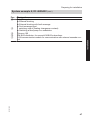
Index
Index
Installation instructions
Preparing for installation
Product information..............................................................................................
Overview of system examples..............................................................................
Designations in the system schemes...................................................................
System example 1, ID: 4605419..........................................................................
System example 2, ID: 4605421..........................................................................
System example 3, ID: 4605422..........................................................................
System example 4, ID: 4605423..........................................................................
System example 5, ID: 4605424..........................................................................
System example 6, ID: 4605428..........................................................................
System example 7, ID: 4605431..........................................................................
System example 8, ID: 4605432..........................................................................
System example 9, ID: 4605434..........................................................................
System extension.................................................................................................
7
7
8
9
14
19
23
28
34
40
45
51
56
Installation sequence
Overview of electrical connections....................................................................... 65
Inserting cables and applying strain relief............................................................ 66
Inserting the boiler coding card............................................................................ 67
Adjusting the high limit safety cut-out (if required)............................................... 68
Changing the temperature controller setting (if required)..................................... 69
Connecting sensors.............................................................................................. 71
Connecting pumps............................................................................................... 71
Connecting servomotors...................................................................................... 73
Connecting the central fault message facility....................................................... 74
Connecting the external safety equipment........................................................... 74
Provisional burner operation................................................................................ 76
External blocking – single boiler system.............................................................. 76
External changeover of multi stage/modulating burners...................................... 78
Single boiler system – connecting an external control unit.................................. 78
Multi boiler system – connecting an external control unit..................................... 84
Connecting an AC burner..................................................................................... 92
Connecting a three-phase burner......................................................................... 96
Power supply........................................................................................................ 99
Power supply in conjunction with Vitocrossal, type CT2...................................... 100
Fitting the front part of the control unit.................................................................. 101
Opening the control unit....................................................................................... 102
Commissioning
Testing the high limit safety cut-out...................................................................... 103
4
5600 634 GB
Service instructions
Index
Index
Matching the coding addresses to the system version......................................... 103
Checking actuators and sensors.......................................................................... 105
Integrating a control unit into the LON.................................................................. 106
Entering a service PIN for LON subscribers......................................................... 107
Entering a PIN code for Vitocom 100................................................................... 108
Service scans
Calling up the service level................................................................................... 109
Leaving the service level...................................................................................... 109
Scanning operating data...................................................................................... 109
Brief scan............................................................................................................. 109
Scanning and resetting service display................................................................ 111
Troubleshooting
Fault display......................................................................................................... 113
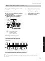
Function description
Boiler water temperature control.......................................................................... 125
Cylinder temperature control................................................................................ 133
Code 1
Calling up coding level 1...................................................................................... 137
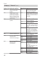
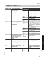
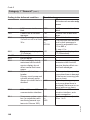
Category 1 "General"........................................................................................... 138
Category 2 "Boiler"............................................................................................... 139
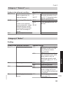
Category 3 "DHW"................................................................................................ 140
Category 4 "Solar"................................................................................................ 141
Code 2
Calling up coding level 2...................................................................................... 143
Category 1 "General"........................................................................................... 144
Category 2 "Boiler"............................................................................................... 149
Category 3 "DHW"................................................................................................ 154
Category 4 "Solar"................................................................................................ 156
5600 634 GB
Designs
Connection and wiring diagram............................................................................ 163
Components
Boiler coding card................................................................................................. 169
Sensors................................................................................................................ 169
Plug-in adaptor for ext. safety equipment, part no. 7164 404.............................. 171
Extension EA1...................................................................................................... 173
Secondary air device Vitoair, part no. 7338 725, 7339 703................................. 175
5
Index
Index (cont.)
Parts list.............................................................................................................. 177
Specification....................................................................................................... 179
5600 634 GB
Keyword index.................................................................................................... 180
6
Preparing for installation
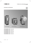
Product information
This document describes Vitotronic 100
when used:
■ in a single boiler system
■ in a multi boiler system with higher
third party control unit
These instructions are not required for
multi boiler systems with the
Vitotronic 300-K.
Boiler
Single boiler systems
1
Vitoplex, Vitorond
2
Vitoplex, Vitomax,
Vitorond
3
Vitocrossal
5600 634 GB
Multi boiler systems
4
Vitoplex, Vitorond
5
Vitomax, Vitoplex,
Vitorond
6
Vitomax,Vitoplex,
Vitorond
7
Vitocrossal, Vitoplex,
Vitorond
8
Vitocrossal, Vitomax,
Vitoplex, Vitorond
9
Vitocrossal, Vitomax,
Vitoplex, Vitorond
Characteristics
Page
Therm-Control
Shunt pump and 3-way mixing valve for
raising the return temperature
Several heating circuits and one low
temperature heating circuit
9
14
Therm-Control
Shunt pump for every boiler for return
temperature raising
3-way mixing valve for raising the return
temperature
Several heating circuits and one low
temperature heating circuit, Therm-Control
Several heating circuits and one low
temperature heating circuit and low temperature boiler with shunt pump
Several heating circuits and one low
temperature heating circuit and low temperature boiler with 3-way mixing valve
and boiler circuit pump
23
28
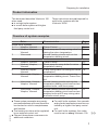
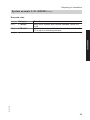
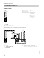
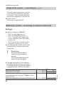
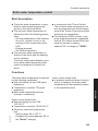
■ These system examples are merely
recommendations and must therefore
be checked on site for completeness
and function.
■ The heating circuits must be regulated
by an external control unit.
■ Connect three-phase consumers via
additional contactors.
Installation
Overview of system examples
19
34
40
45
51
■ For multi boiler systems, the cascade
and cylinder temperature must be controlled by a higher third party control
unit.
■ For multi boiler systems, the codes
must be set on every Vitotronic 100.
7
Preparing for installation
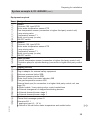
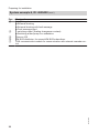
Overview of system examples (cont.)
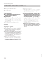
■ For connecting a single boiler system
to a higher third party control unit, see
page 78.
■ For connecting a multi boiler system to
a higher third party control unit, see
page 84.
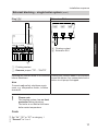
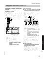
Designations in the system schemes
eE
qE
2/21
rR
2/52M1 M
21
28
50
20M1
qE
2/52M2 M
2/21
2
2/28
3
X2
4
21
28
50
20M1
52M1
52M2
8
(5Sol)
(6)
40
20M2,24
145
1
5
2M1
2/1
qW
2/5
qQ
2
qR
2/5
40
20M2,24
145
1
5
2M1
2M2
2/5Sol
26/S2
qQ
9
5600 634 GB
1
8
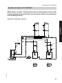
Preparing for installation
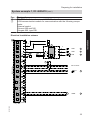
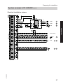
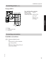
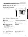
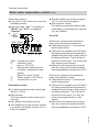
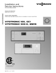
System example 1, ID: 4605419
Single boiler system: Boiler with Therm-Control
Hydraulic installation scheme
13
Installation
13
12
--2/21--
--2/3/2--
3
5
--2/17A--
WW
11
--2/5A--
10
1
--5A---KM BUS---17A---3/2--
KW
5600 634 GB
--230V---21--
2
9
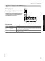
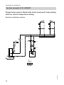
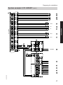
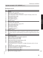
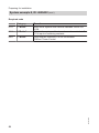
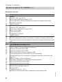
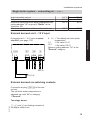
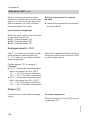
Preparing for installation
System example 1, ID: 4605419 (cont.)
Equipment required
Pos.
1
2
3
5
tP
qP
qQ
qW
qE
eP
eQ
eW
eE
eT
rR
rT
rZ
rU
wI
wO
eR
rP
rQ
rW
rE
5600 634 GB
rI
Designation
Boiler
Vitotronic 100, type GC1B
Boiler water temperature sensor KTS
Therm-Control temperature sensor
ON/OFF switch
DHW cylinder
Cylinder temperature sensor STS
Circulation pump for cylinder heating UPSB
Heating circuits
Boiler accessories
Plug-in adaptor for external safety equipment
Minimum pressure limiter SDB
Maximum pressure limiter SDB
Water level limiter (low water indicator) WB
Flue gas temperature sensor AGS
External hook-ups (for connection to a higher third party control unit, see
page 78):
■ External demand, load-dependent
■ External changeover of stepped/modulating burners
■ External demand burner stage 2
■ External demand burner stage 1
System accessories
Contactor relay
Downstream heating circuit controller, contact closed: Signal for mixer
"Close"
Central fault message system S
Extension EA 1
1 analogue input (0 – 10 V):
■ Specification of the set boiler water temperature
3 digital inputs:
■ External blocking
■ External blocking with fault message
■ Fault message input
1 switching output (floating changeover contact):
■ Switching a feed pump to a substation
Vitocom 100
10
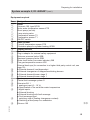
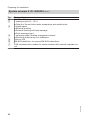
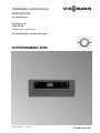
Preparing for installation
System example 1, ID: 4605419 (cont.)
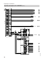
Pos.
rO
tQ
Designation
KM BUS distributor, for several KM BUS subscribers
LON communication module for communication with the following components:
External control
Vitocom 200 and 300
Vitogate 200, type EIB
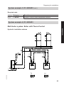
2
90
151
41
30
7
4
7
4
P
150
P
N
156
41
4
90
L
40
2
40
145
3
2
1
4
145
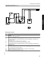
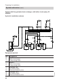
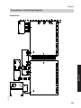
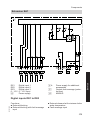
SDB
31
SDB
32
WB
33
N
156
L
50
230 V / 50 Hz
L
40
230 V/ 50 Hz
N
N
50
S
L
34
N
29
L
N
20 A1
L
N
52 A1
N
21
L
M
1~
UPSB
12
N
L
5600 634 GB
28
11
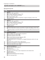
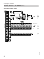
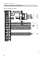
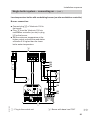
Installation
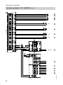
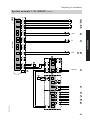
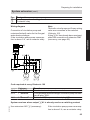
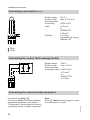
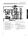
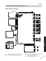
Electrical installation scheme
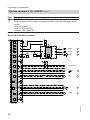
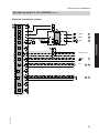
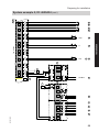
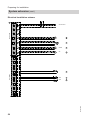
Preparing for installation
System example 1, ID: 4605419 (cont.)
2
146
3
2
1
45
143
3
2
1
47
46
4
3
2
1
AGS
35
4
3
2
1
T1
5
4
3
2
1
STS
11
3/2
2
1
KTS
3
1
3
2
1
KM BUS
48
9
15
17B
17A
Low voltage
44
5B
5A
145
145
49
145
30
4
3
2
1
LON
145
51
3
2
1
145
3
2
1
145
3
2
1
3
2
1
40
156
N
40
L
N
40A
157
0-10V
DE3
DE2
DE1
1
2
12
145
L
P
Ö
S
43
4
3
41
2
1
2
1
2
1
42
42
42
5600 634 GB
2
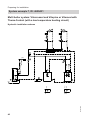
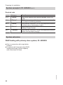
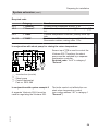
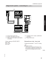
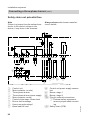
Preparing for installation
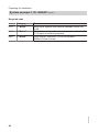
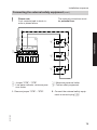
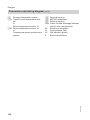
System example 1, ID: 4605419 (cont.)
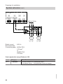
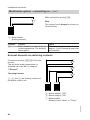
A1
Wiring diagram
20
L
N
Closing mixers installed downstream via
Therm-Control temperature sensor in
heating systems with heating circuit control units that are not connected to the
boiler control unit via LON.
1
2 ...
Installation
K
n
Required code
Category
2 "Boiler"
4C:2
1 "General"
Function
Therm-Control temperature sensor affects the mixers of
downstream heating circuits.
Connection at plug sÖ affects the mixers of downstream
heating circuits.
5600 634 GB
0d:1
13
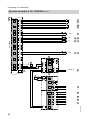
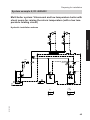
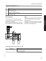
Preparing for installation
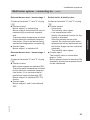
System example 2, ID: 4605421
Single boiler system: Boiler with shunt pump and 3-way mixing
valve for return temperature raising
Hydraulic installation scheme
--2/21-6
--2/29--
7
5
--2/3/2--
12
WW
13
--2/52A1--
13
3
--2/17B--
--2/17A-8
11
--2/5A--
10
1
--5A---KM BUS---17A---3/2---17B--
KW
5600 634 GB
--52A1---29--
--230V---21--
2
14
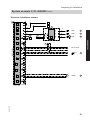
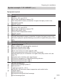
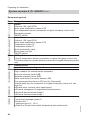
Preparing for installation
System example 2, ID: 4605421 (cont.)
Equipment required
eP
eQ
eW
eE
eT
rR
rT
rZ
rU
eR
rP
rQ
rW
rE
5600 634 GB
rI
Designation
Boiler
Vitotronic 100, type GC1B
Boiler water temperature sensor KTS
Shunt pump (on site)
3-way mixing valve
Temperature sensor T2
Temperature sensor T1
ON/OFF switch
DHW cylinder
Cylinder temperature sensor STS
Circulation pump for cylinder heating UPSB
Heating circuits
Boiler accessories
Plug-in adaptor for external safety equipment
Minimum pressure limiter SDB
Maximum pressure limiter SDB
Water level limiter (low water indicator) WB
Flue gas temperature sensor AGS
External hook-ups (for connection to a higher third party control unit, see
page 78):
■ External demand, load-dependent
■ External changeover of stepped/modulating burners
■ External demand burner stage 2
■ External demand burner stage 1
System accessories
Central fault message system S
Extension EA 1
1 analogue input (0 – 10 V):
■ Specification of the set boiler water temperature
3 digital inputs:
■ External blocking
■ External blocking with fault message
■ Fault message input
1 switching output (floating changeover contact):
■ Switching a feed pump to a substation
Vitocom 100
Installation
Pos.
1
2
3
5
6
7
8
tP
qP
qQ
qW
qE
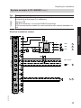
15
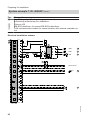
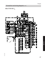
Preparing for installation
System example 2, ID: 4605421 (cont.)
Pos.
rO
tQ
Designation
KM BUS distributor, for several KM BUS subscribers
LON communication module for communication with the following components:
External control
Vitocom 200 and 300
Vitogate 200, type EIB
Electrical installation scheme
2
90
151
41
30
7
4
7
4
P
150
P
N
156
41
4
90
L
40
2
40
145
3
2
1
4
145
SDB
31
SDB
32
WB
33
N
156
L
50
230 V / 50 Hz
L
40
230 V/ 50 Hz
N
N
50
N
29
S
L
L
M
1~
BP
34
5
N
20 A1
L
N
M
1~
52 A1
N
21
L
M
1~
6
UPSB
12
N
L
5600 634 GB
28
16
Preparing for installation
System example 2, ID: 4605421 (cont.)
146
3
2
1
45
143
3
2
1
47
9
15
46
4
3
2
1
AGS
35
T2
7
T1
8
4
3
2
1
STS
11
3/2
2
1
KTS
3
1
3
2
1
KM BUS
48
17B
17A
Low voltage
44
5B
5A
145
145
4
3
2
1
49
145
30
4
3
2
1
LON
145
51
3
2
1
145
3
2
1
145
3
2
1
3
2
1
40
2
156
N
40
L
N
40A
157
0-10V
DE3
DE2
5600 634 GB
DE1
1
2
L
P
Ö
S
43
4
3
41
2
1
2
1
2
1
42
42
42
145
17
Installation
2
Preparing for installation
System example 2, ID: 4605421 (cont.)
Required code
Category
2 "Boiler"
Function
Constant return temperature control.
5600 634 GB
0C:1
18
Preparing for installation
System example 3, ID: 4605422
Single boiler system with Vitocrossal
Hydraulic installation scheme
13
Installation
13
12
--2/21--
--2/3/2--
WW
3
11
--2/5A--
5
10
1
--5A--
--KM BUS---3/2--
KW
5600 634 GB
--230V---21--
2
19
Preparing for installation
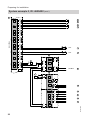
System example 3, ID: 4605422 (cont.)
Equipment required
Pos.
1
2
3
5
tP
qP
qQ
qW
qE
eP
eQ
eW
eE
rR
rT
rZ
rU
eR
rP
rQ
rW
rE
5600 634 GB
rI
rO
tQ
Designation
Boiler
Vitotronic 100, type GC1B
Boiler water temperature sensor KTS
Neutralising system
ON/OFF switch
DHW cylinder
Cylinder temperature sensor STS
Circulation pump for cylinder heating UPSB
Heating circuits
Boiler accessories
Plug-in adaptor for external safety equipment
Minimum pressure limiter SDB
Maximum pressure limiter SDB
Water level limiter (low water indicator) WB
External hook-ups (for connection to a higher third party control unit, see
page 78):
■ External demand, load-dependent
■ External changeover of stepped/modulating burners
■ External demand burner stage 2
■ External demand burner stage 1
System accessories
Central fault message system S
Extension EA 1
1 analogue input (0 – 10 V):
■ Specification of the set boiler water temperature
3 digital inputs:
■ External blocking
■ External blocking with fault message
■ Fault message input
1 switching output (floating changeover contact):
■ Switching a feed pump to a substation
Vitocom 100
KM BUS distributor, for several KM BUS subscribers
LON communication module for communication with external cascade control
20
Preparing for installation
System example 3, ID: 4605422 (cont.)
Electrical installation scheme
2
90
151
30
7
4
7
4
P
150
P
N
L
40
2
40
145
3
2
1
4
145
SDB
31
SDB
32
WB
33
Installation
41
156
41
4
90
N
156
L
50
230 V / 50 Hz
L
40
230 V/ 50 Hz
N
N
50
S
L
34
N
29
L
N
20 A1
L
N
52 A1
N
21
L
M
1~
UPSB
12
N
L
5600 634 GB
28
21
Preparing for installation
System example 3, ID: 4605422 (cont.)
2
146
3
2
1
45
143
3
2
1
47
9
15
17B
Low voltage
17A
5B
5A
3/2
1
145
145
44
46
4
3
2
1
4
3
2
1
4
3
2
1
2
1
11
KTS
3
KM BUS
48
49
3
2
1
4
3
2
1
STS
145
30
145
LON
3
2
1
145
3
2
1
145
3
2
1
3
2
1
40
2
156
N
40
L
N
40A
157
0-10V
DE3
DE2
DE1
43
4
3
41
2
1
2
1
2
1
42
42
42
145
5600 634 GB
1
2
L
P
Ö
S
22
Preparing for installation
System example 3, ID: 4605422 (cont.)
Required code
0C:0
Category
2 "Boiler"
Function
Without Therm-Control temperature sensor.
System example 4, ID: 4605423
Installation
Multi boiler system: Boiler with Therm-Control
Hydraulic installation scheme
18
18
6
16
--10/52A1--
--2/52A1-5
--10/3/2--
--2/17A--
--2/3/2--
13
3
4
11
--10/17A--
WW
12
15
14
1
9
--17A---3/2-10
--230V---52A1--
2
--230V---52A1--
5600 634 GB
--17A---3/2--
KW
23
Preparing for installation
System example 4, ID: 4605423 (cont.)
Pos.
1
2
3
4
5
6
tP
9
qP
qQ
qW
qE
tP
qR
qT
qZ
qI
eP
eQ
eW
eE
eT
rR
rT
rZ
rU
eR
rP
rQ
rW
24
Designation
Boiler I
Vitotronic 100, type GC1B
Boiler water temperature sensor KTS
Therm-Control temperature sensor
Motorised butterfly valve
Flow temperature sensor (connection to higher third party control unit)
ON/OFF switch
Boiler II
Vitotronic 100, type GC1B
Boiler water temperature sensor KTS
Therm-Control temperature sensor
Motorised butterfly valve
ON/OFF switch
DHW cylinder
Cylinder temperature sensor (connection to higher third party control unit)
Circulation pump for cylinder heating (connection to higher third party control
unit)
Heating circuits
Boiler accessories
Plug-in adaptor for external safety equipment
Minimum pressure limiter SDB
Maximum pressure limiter SDB
Water level limiter (low water indicator) WB
Flue gas temperature sensor AGS
External hook-ups (for connection to a higher third party control unit, see
page 78):
■ Enable boiler, butterfly valve open/closed
■ External changeover of stepped/modulating burners
■ External demand burner stage 2
■ External demand burner stage 1
System accessories
Central fault message system S
Extension EA 1
1 analogue input (0 – 10 V):
■ Default of the set boiler water temperature and enable boiler
3 digital inputs:
■ External blocking
■ External blocking with fault message
■ Fault message input
5600 634 GB
Equipment required
Preparing for installation
System example 4, ID: 4605423 (cont.)
Pos.
rE
rI
rO
tQ
Designation
1 switching output (floating changeover contact):
■ Switching a feed pump to a substation
Vitocom 100
KM BUS distributor, for several KM BUS subscribers
LON communication module for communication with external cascade control
2 /
10
90
151
41
30
7
4
7
4
P
150
P
N
156
41
4
90
L
40
2 / 10
40
145
3
2
1
4
145
SDB
31
SDB
32
WB
33
N
156
L
50
230 V / 50 Hz
L
40
230 V/ 50 Hz
N
N
50
S
L
34
N
29
L
N
20 A1
L
N
M
1~
52 A1
5 / 13
N
21
L
N
L
5600 634 GB
28
25
Installation
Electrical installation scheme
Preparing for installation
System example 4, ID: 4605423 (cont.)
2 /
146
3
2
1
45
143
3
2
1
47
10
9
15
17B
Low voltage
17A
5B
5A
AGS
4
3
2
1
T1
4 / 12
KTS
3 / 11
35
4
3
2
1
2
1
1
3
2
1
145
46
4
3
2
1
3/2
145
44
49
30
4
3
2
1
LON
145
145
51
3
2
1
145
3
2
1
145
3
2
1
3
2
1
KM BUS
48
40
156
N
40
L
N
40A
157
0-10V
DE3
DE2
DE1
1
2
26
145
L
P
Ö
S
43
4
3
41
2
1
2
1
2
1
42
42
42
5600 634 GB
2 / 10
Preparing for installation
System example 4, ID: 4605423 (cont.)
Required code
Category
2 "Boiler"
01:3
2 "Boiler"
Function
Multi boiler system with external cascade control via
LON.
Multi boiler system with external cascade control via 0 –
10 V input or switching contacts.
5600 634 GB
Installation
01:2
27
Preparing for installation
System example 5, ID: 4605424
Multi boiler system: Any boiler with shunt pump for return temperature raising
Hydraulic installation scheme
22
22
6
3
14
--2/17A-10
15
--12/29--
9
--2/17B--
--12/3/2--
--2/52A1--
--2/29--
7
8
--2/3/2--
WW
--12/52A1--
20
--12/17B--
16
--12/17A-13
17
19
18
1
11
--17A---3/2---17B-12
--230V---52A1---29--
5600 634 GB
--17A---3/2---17B-2
--230V---52A1---29--
KW
28
Preparing for installation
System example 5, ID: 4605424 (cont.)
Pos.
1
2
3
6
7
8
9
qP
tP
qQ
qW
qE
qR
qT
qZ
qU
tP
qI
qO
wP
wW
eP
eQ
eW
eE
eR
eT
5600 634 GB
rR
rT
rZ
rU
eR
Designation
Boiler I
Vitotronic 100, type GC1B
Boiler water temperature sensor KTS
Flow temperature sensor (connection to higher third party control unit)
Motorised butterfly valve
Temperature sensor T2
Shunt pump (on site)
Temperature sensor T1
ON/OFF switch
Boiler II
Vitotronic 100, type GC1B
Boiler water temperature sensor KTS
Motorised butterfly valve
Temperature sensor T2
Shunt pump (on site)
Temperature sensor T1
ON/OFF switch
DHW cylinder
Cylinder temperature sensor (connection to higher third party control unit)
Circulation pump for cylinder heating (connection to higher third party control
unit)
Heating circuits
Boiler accessories
Plug-in adaptor for external safety equipment
Minimum pressure limiter SDB
Maximum pressure limiter SDB
Water level limiter (low water indicator) WB
Central fault message system S
Flue gas temperature sensor AGS
External hook-ups (for connection to a higher third party control unit, see
page 78):
■ Enable boiler, butterfly valve open/closed
■ External changeover of stepped/modulating burners
■ External demand burner stage 2
■ External demand burner stage 1
System accessories
Central fault message system S
29
Installation
Equipment required
Preparing for installation
System example 5, ID: 4605424 (cont.)
Pos.
rP
rQ
rW
rE
5600 634 GB
rI
rO
tQ
Designation
Extension EA 1
1 analogue input (0 – 10 V):
■ Default of the set boiler water temperature and enable boiler
3 digital inputs:
■ External blocking
■ External blocking with fault message
■ Fault message input
1 switching output (floating changeover contact):
■ Switching a feed pump to a substation
Vitocom 100
KM BUS distributor, for several KM BUS subscribers
LON communication module for communication with external cascade control
30
Preparing for installation
System example 5, ID: 4605424 (cont.)
Electrical installation scheme
90
151
41
30
7
4
7
4
P
150
P
N
156
41
4
90
L
40
2 / 12
40
145
3
2
1
4
145
SDB
31
SDB
32
WB
33
Installation
2 /
12
N
156
L
50
230 V / 50 Hz
L
40
230 V/ 50 Hz
N
N
50
N
29
S
L
L
M
1~
BP
34
9 / 16
N
20 A1
L
N
M
1~
52 A1
7 / 14
N
21
L
N
L
5600 634 GB
28
31
Preparing for installation
System example 5, ID: 4605424 (cont.)
2 /
12
146
3
2
1
45
143
3
2
1
47
9
15
17B
Low voltage
17A
5B
5A
AGS
4
3
2
1
35
T2
8 / 15
T1
10 / 17
KTS
3 / 13
4
3
2
1
2
1
1
3
2
1
145
46
4
3
2
1
3/2
145
44
49
145
30
4
3
2
1
LON
145
51
3
2
1
145
3
2
1
145
3
2
1
3
2
1
KM BUS
48
40
156
N
40
L
N
40A
157
0/-10V
DE3
DE2
DE1
1
2
32
145
L
P
Ö
S
43
4
3
41
2
1
2
1
2
1
42
42
42
5600 634 GB
2
Preparing for installation
System example 5, ID: 4605424 (cont.)
Required code
Category
2 "Boiler"
01:2
2 "Boiler"
Function
Multi boiler system with external cascade control via
LON.
Multi boiler system with external cascade control via 0 –
10 V input or switching contacts.
5600 634 GB
Installation
01:2
33
Preparing for installation
System example 6, ID: 4605428
Multi boiler system: Any boiler with boiler circuit pump and 3way mixing valve for return temperature raising
Hydraulic installation scheme
20
20
6
18
WW
--2/3/2--
7
--2/17A-3
8
--11/52A1--
15
--11/29--
13
--11/3/2--
--2/52A1--
9
--2/29--
--11/17A-12
14
17
16
1
10
--17A---3/2-11
5600 634 GB
--230V---52A1---29--
2
--230V---52A1---29--
--17A---3/2--
KW
34
Preparing for installation
System example 6, ID: 4605428 (cont.)
Pos.
1
2
3
6
7
8
9
tP
qP
qQ
qW
qE
qR
qT
tP
qZ
qU
qI
wP
eP
eQ
eW
eE
eT
rR
rT
rZ
rU
5600 634 GB
eR
rP
rQ
Designation
Boiler I
Vitotronic 100, type GC1B
Boiler water temperature sensor KTS
Flow temperature sensor (connection to higher third party control unit)
3-way mixing valve
Temperature sensor T1
Boiler circuit pump (on site)
ON/OFF switch
Boiler II
Vitotronic 100, type GC1B
Boiler water temperature sensor KTS
3-way mixing valve
Temperature sensor T1
Boiler circuit pump (on site)
ON/OFF switch
DHW cylinder
Cylinder temperature sensor (connection to higher third party control unit)
Circulation pump for cylinder heating (connection to higher third party control
unit)
Heating circuits
Boiler accessories
Plug-in adaptor for external safety equipment
Minimum pressure limiter SDB
Maximum pressure limiter SDB
Water level limiter (low water indicator) WB
Flue gas temperature sensor AGS
External hook-ups (for connection to a higher third party control unit, see
page 78):
■ Boiler enable, 3-way mixing valve, control mode/close
■ External changeover of stepped/modulating burners
■ External demand burner stage 2
■ External demand burner stage 1
System accessories
Central fault message system S
Extension EA 1
1 analogue input (0 – 10 V):
■ Default of the set boiler water temperature and enable boiler
35
Installation
Equipment required
Preparing for installation
System example 6, ID: 4605428 (cont.)
Pos.
rW
rE
5600 634 GB
rI
rO
tQ
Designation
3 digital inputs:
■ External blocking
■ External blocking with fault message
■ Fault message input
1 switching output (floating changeover contact):
■ Switching a feed pump to a substation
Vitocom 100
KM BUS distributor, for several KM BUS subscribers
LON communication module for communication with external cascade control
36
Preparing for installation
System example 6, ID: 4605428 (cont.)
Electrical installation scheme
90
151
41
30
7
4
7
4
P
150
P
N
156
41
4
90
L
40
2 / 11
40
145
3
2
1
4
145
SDB
31
SDB
32
WB
33
Installation
2 /
11
N
156
L
50
230 V / 50 Hz
L
40
230 V/ 50 Hz
N
N
50
N
29
S
L
L
M
1~
KKP
34
9 / 15
N
20 A1
L
N
M
1~
52 A1
7 / 13
N
21
L
N
L
5600 634 GB
28
37
Preparing for installation
System example 6, ID: 4605428 (cont.)
2 /
11
146
3
2
1
45
143
3
2
1
47
9
15
17B
Low voltage
17A
5B
5A
AGS
4
3
2
1
T1
8 / 14
KTS
3 / 12
35
4
3
2
1
2
1
1
3
2
1
145
46
4
3
2
1
3/2
145
44
49
145
30
4
3
2
1
LON
145
51
3
2
1
145
3
2
1
145
3
2
1
3
2
1
KM BUS
48
40
156
N
40
L
N
40A
157
0-10V
DE3
DE2
DE1
1
2
38
145
L
P
Ö
S
43
4
3
41
2
1
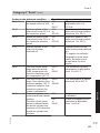
2
1
2
1
42
42
42
5600 634 GB
2
Preparing for installation
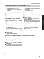
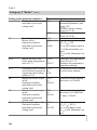
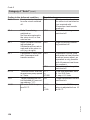
System example 6, ID: 4605428 (cont.)
Required code
Category
2 "Boiler"
01:3
2 "Boiler"
0C:1
4d:2
2 "Boiler"
1 "General"
Function
Multi boiler system with external cascade control via
LON.
Multi boiler system with external cascade control via 0 –
10 V input or switching contacts.
Constant return temperature control.
Boiler circuit pump at plug sL
5600 634 GB
Installation
01:2
39
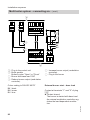
Preparing for installation
System example 7, ID: 4605431
Multi boiler system: Vitocrossal and Vitoplex or Vitorond with
Therm-Control (with a low temperature heating circuit)
Hydraulic installation scheme
20
21
4
WW
16
--10/52A1--
13
--10/3/2--
3
11
-10/17A-
--2/3/2--
12
15
7
14
1
9
--17A--
--3/2-10
5600 634 GB
--230V--
2
--230V---52A1--
--3/2--
KW
40
Preparing for installation
System example 7, ID: 4605431 (cont.)
Pos.
1
2
3
4
7
tP
9
qP
qQ
qW
qE
tP
qR
qT
qZ
wP
wQ
eP
eQ
eW
eE
eT
rR
rT
rZ
rU
eR
rP
rQ
5600 634 GB
rW
Designation
Boiler I
Vitotronic 100, type GC1B
Boiler water temperature sensor KTS
Flow temperature sensor (connection to higher third party control unit)
Neutralising system
ON/OFF switch
Boiler II
Vitotronic 100, type GC1B
Boiler water temperature sensor KTS
Motorised butterfly valve
Therm-Control temperature sensor
ON/OFF switch
DHW cylinder
Cylinder temperature sensor (connection to higher third party control unit)
Circulation pump for cylinder heating (connection to higher third party control
unit)
Heating circuit
Low temperature heating circuit
Boiler accessories
Plug-in adaptor for external safety equipment
Minimum pressure limiter SDB
Maximum pressure limiter SDB
Water level limiter (low water indicator) WB
Flue gas temperature sensor AGS (not for Vitocrossal)
External hook-ups (for connection to a higher third party control unit, see
page 78):
■ Enable boiler, butterfly valve open/closed
■ External changeover of stepped/modulating burners
■ External demand burner stage 2
■ External demand burner stage 1
System accessories
Central fault message system S
Extension EA 1
1 analogue input (0 – 10 V):
■ Default of the set boiler water temperature and enable boiler
3 digital inputs:
■ External blocking
■ External blocking with fault message
■ Fault message input
41
Installation
Equipment required
Preparing for installation
System example 7, ID: 4605431 (cont.)
Pos.
rE
rI
rO
tQ
Designation
1 switching output (floating changeover contact):
■ Switching a feed pump to a substation
Vitocom 100
KM BUS distributor, for several KM BUS subscribers
LON communication module for communication with external cascade control
Electrical installation scheme
2 /
10
90
151
41
30
7
4
7
4
P
150
P
N
156
41
4
90
L
40
2 / 10
40
145
3
2
1
4
145
SDB
31
SDB
32
WB
33
N
156
L
50
230 V / 50 Hz
L
40
230 V/ 50 Hz
N
N
50
S
L
34
N
29
L
N
20 A1
L
N
M
1~
52 A1
12
N
21
L
N
L
5600 634 GB
28
42
Preparing for installation
System example 7, ID: 4605431 (cont.)
2 /
146
3
2
1
45
143
3
2
1
47
9
15
17B
Low voltage
17A
5B
5A
AGS
35
4
3
2
1
T1
13
4
3
2
1
2
1
1
3
2
1
145
46
4
3
2
1
3/2
145
44
KTS
49
145
30
4
3
2
1
LON
3 / 11
145
51
3
2
1
145
3
2
1
145
3
2
1
3
2
1
KM BUS
48
40
2
156
N
40
L
N
40A
157
0-10V
DE3
DE2
5600 634 GB
DE1
1
2
L
P
Ö
S
43
4
3
41
2
1
2
1
2
1
42
42
42
145
43
Installation
10
Preparing for installation
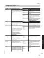
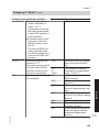
System example 7, ID: 4605431 (cont.)
Required code
Category
2 "Boiler"
01:3
2 "Boiler"
0d:0
2 "Boiler"
Function
Multi boiler system with external cascade control via
LON.
Multi boiler system with external cascade control via 0 –
10 V input or switching contacts.
Only with the Vitotronic 100 for Vitocrossal:
Without Therm-Control.
5600 634 GB
01:2
44
Preparing for installation
System example 8, ID: 4605432
Multi boiler system: Vitocrossal and low temperature boiler with
shunt pump for raising the return temperature (with a low temperature heating circuit)
Hydraulic installation scheme
21
Installation
20
4
18
--10/52A1--
--10/3/2--
--2/3/2--
14
--10/29--
WW
3
--10/17B-12
15
11
--10/17A-13
17
7
16
1
9
--17A---17B---3/2-10
--230V---52A1---29--
--3/2-2
5600 634 GB
--230V--
KW
45
Preparing for installation
System example 8, ID: 4605432 (cont.)
Pos.
1
2
3
4
7
tP
9
qP
qQ
qW
qE
qR
qT
tP
qZ
qU
qI
wP
wQ
eP
eQ
eW
eE
eT
rR
rT
rZ
rU
eR
rP
rQ
46
Designation
Boiler I
Vitotronic 100, type GC1B
Boiler water temperature sensor KTS
Flow temperature sensor (connection to higher third party control unit)
Neutralising system
ON/OFF switch
Boiler II
Vitotronic 100, type GC1B
Boiler water temperature sensor KTS
Temperature sensor T2
Temperature sensor T1
Motorised butterfly valve
Shunt pump (on site)
ON/OFF switch
DHW cylinder
Cylinder temperature sensor (connection to higher third party control unit)
Circulation pump for cylinder heating (connection to higher third party control
unit)
Heating circuit
Low temperature heating circuit
Boiler accessories
Plug-in adaptor for external safety equipment
Minimum pressure limiter SDB
Maximum pressure limiter SDB
Water level limiter (low water indicator) WB
Flue gas temperature sensor AGS (not for Vitocrossal)
External hook-ups (for connection to a higher third party control unit, see
page 78):
■ Enable boiler, butterfly valve open/closed
■ External changeover of stepped/modulating burners
■ External demand burner stage 2
■ External demand burner stage 1
System accessories
Central fault message system S
Extension EA 1
1 analogue input (0 – 10 V):
■ Default of the set boiler water temperature and enable boiler
5600 634 GB
Equipment required
Preparing for installation
Pos.
rW
rE
5600 634 GB
rI
rO
tQ
Designation
3 digital inputs:
■ External blocking
■ External blocking with fault message
■ Fault message input
1 switching output (floating changeover contact):
■ Switching a feed pump to a substation
Vitocom 100
KM BUS distributor, for several KM BUS subscribers
LON communication module for communication with external cascade control
47
Installation
System example 8, ID: 4605432 (cont.)
Preparing for installation
System example 8, ID: 4605432 (cont.)
Electrical installation scheme
2 /
10
90
151
41
30
7
4
7
4
P
150
P
N
156
41
4
90
L
40
2 / 10
40
145
3
2
1
4
145
SDB
31
SDB
32
WB
33
N
156
L
50
230 V / 50 Hz
L
40
230 V/ 50 Hz
N
N
50
N
29
S
L
L
M
1~
BP
34
15
N
20 A1
L
N
M
1~
52 A1
14
N
21
L
N
L
5600 634 GB
28
48
Preparing for installation
System example 8, ID: 4605432 (cont.)
2 /
146
3
2
1
45
143
3
2
1
47
9
15
17B
Low voltage
17A
5B
5A
4
3
2
1
AGS
35
T2
12
T1
13
4
3
2
1
2
1
1
3
2
1
145
46
4
3
2
1
3/2
145
44
KTS
49
145
30
4
3
2
1
LON
3 / 11
145
51
3
2
1
145
3
2
1
145
3
2
1
3
2
1
KM BUS
48
40
2
156
N
40
L
N
40A
157
0-10V
DE3
DE2
5600 634 GB
DE1
1
2
L
P
Ö
S
43
4
3
41
2
1
2
1
2
1
42
42
42
145
49
Installation
10
Preparing for installation
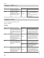
System example 8, ID: 4605432 (cont.)
Required code
Category
2 "Boiler"
01:3
2 "Boiler"
0d:0
2 "Boiler"
Function
Multi boiler system with external cascade control via
LON.
Multi boiler system with external cascade control via 0 –
10 V input or switching contacts.
Only with the Vitotronic 100 for Vitocrossal:
Without Therm-Control.
5600 634 GB
01:2
50
Preparing for installation
System example 9, ID: 4605434
Multi boiler system: Vitocrossal and low temperature boiler with
3-way mixing valve and boiler circuit pump (with a low temperature heating circuit)
Hydraulic installation scheme
21
Installation
20
4
17
WW
--10/52A1-13
--10/3/2--
--2/3/2--
12
--10/29--
3
--10/17A-11
14
16
7
15
1
9
--17A---3/2-10
5600 634 GB
--230V--
2
--230V---52A1---29--
--3/2--
KW
51
Preparing for installation
System example 9, ID: 4605434 (cont.)
Equipment required
Pos.
1
2
3
4
7
tP
9
qP
qQ
qW
qE
qR
tP
qT
qZ
qU
wP
wQ
eP
eQ
eW
eE
eT
rR
rT
rZ
rU
5600 634 GB
eR
rP
rQ
Designation
Boiler I
Vitotronic 100, type GC1B
Boiler water temperature sensor KTS
Flow temperature sensor (connection to higher third party control unit)
Neutralising system
ON/OFF switch
Boiler II
Vitotronic 100, type GC1B
Boiler water temperature sensor KTS
Boiler circuit pump
3-way mixing valve
Temperature sensor T1
ON/OFF switch
DHW cylinder
Cylinder temperature sensor (connection to higher third party control unit)
Circulation pump for cylinder heating (connection to higher third party control
unit)
Heating circuit
Low temperature heating circuit
Boiler accessories
Plug-in adaptor for external safety equipment
Minimum pressure limiter SDB
Maximum pressure limiter SDB
Water level limiter (low water indicator) WB
Flue gas temperature sensor AGS (not for Vitocrossal)
External hook-ups (for connection to a higher third party control unit, see
page 78):
■ Boiler enable, control mode/close
■ External changeover of stepped/modulating burners
■ External demand burner stage 2
■ External demand burner stage 1
System accessories
Central fault message system S
Extension EA 1
1 analogue input (0 – 10 V):
■ Default of the set boiler water temperature and enable boiler
52
Preparing for installation
Pos.
rW
rE
5600 634 GB
rI
rO
tQ
Designation
3 digital inputs:
■ External blocking
■ External blocking with fault message
■ Fault message input
1 switching output (floating changeover contact):
■ Switching a feed pump to a substation
Vitocom 100
KM BUS distributor, for several KM BUS subscribers
LON communication module for communication with external cascade control
53
Installation
System example 9, ID: 4605434 (cont.)
Preparing for installation
System example 9, ID: 4605434 (cont.)
Electrical installation scheme
2 /
10
90
151
41
30
7
4
7
4
P
150
P
N
156
41
4
90
L
40
2 / 10
40
145
3
2
1
4
145
SDB
31
SDB
32
WB
33
N
156
L
50
230 V / 50 Hz
L
40
230 V/ 50 Hz
N
N
50
N
29
S
L
L
34
M
1~
12
M
1~
13
N
20 A1
L
N
52 A1
N
21
L
N
L
5600 634 GB
28
54
Preparing for installation
System example 9, ID: 4605434 (cont.)
2 /
146
3
2
1
45
143
3
2
1
47
9
15
17B
Low voltage
17A
5B
5A
AGS
35
4
3
2
1
T1
14
4
3
2
1
2
1
1
3
2
1
145
46
4
3
2
1
3/2
145
44
KTS
49
145
30
4
3
2
1
LON
3 / 11
145
51
3
2
1
145
3
2
1
145
3
2
1
3
2
1
KM BUS
48
40
2
156
N
40
L
N
40A
157
0-10V
DE3
DE2
5600 634 GB
DE1
1
2
L
P
Ö
S
43
4
3
41
2
1
2
1
2
1
42
42
42
145
55
Installation
10
Preparing for installation
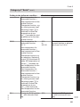
System example 9, ID: 4605434 (cont.)
Required code
01:2
Category
2 "Boiler"
01:3
2 "Boiler"
0C:1
2 "Boiler"
0d:0
2 "Boiler"
4d:2
1 "General"
Function
Multi boiler system with external cascade control via
LON.
Multi boiler system with external cascade control via 0 –
10 V input or switching contacts.
Only with the Vitotronic 100 for low temperature boilers:
Constant return temperature control.
Only with the Vitotronic 100 for Vitocrossal:
Without Therm-Control.
Only with the Vitotronic 100 for low temperature boilers:
Boiler circuit pump at plug sL
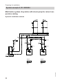
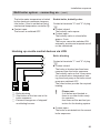
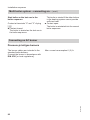
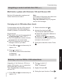
System extension
DHW heating with primary store system; ID: 4605085
5600 634 GB
■ Only in conjunction with single boiler
systems.
■ In systems with temporarily high DHW
demand and large cylinder capacity
with offset draw-off times.
56
Preparing for installation
System extension (cont.)
WW
11
5
--2/5A-10
9
--2/5B-8
--
3
1
--17B---5A---5B--
KW
7
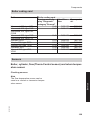
--2/17B--
4
Installation
-2/52A1-
--2/20A1--
6
-2/21-
--230V---21---52A1---20A1--
2
Equipment required
Pos.
1
2
3
4
5
6
7
8
9
5600 634 GB
qP
qQ
Designation
Boiler
Vitotronic 100, type GC1B
Vitotrans 222 (heat exchanger set)
3-way mixing valve (standard delivery of mixer assembly, accessory for
Vitotrans 222)
Primary pump in the primary store system
Secondary pump in the primary store system UPSB
Temperature sensor (standard delivery of mixer assembly, accessory for
Vitotrans 222)
DHW cylinder
Cylinder temperature sensor STS, bottom (standard delivery of mixer assembly, accessory for Vitotrans 222)
Cylinder temperature sensor STS, top (control unit accessory)
DHW circulation pump ZP (on-site)
57
Preparing for installation
System extension (cont.)
Electrical installation scheme
2
Standard LP
L
40
230 V/ 50 Hz
N
N
50
L
230 V/ 50 Hz
N
29
L
N
20 A1
L
M
1~
5
M
1~
4
N
52 A1
N
21
L
N
28
146
3
2
1
143
3
2
1
9
15
17B
17A
Low voltage
L
5B
5A
6
M
1~
ZP
11
4
3
2
1
4
3
2
1
2
1
1
3
2
1
7
STS
9
STS
10
4
3
2
1
5600 634 GB
145
UPSB
4
3
2
1
3/2
145
M
1~
58
Preparing for installation
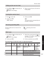
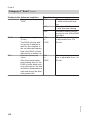
System extension (cont.)
Required code
Category
1 "General"
1 "General"
55:3
3 "DHW"
6A:113
3 "DHW"
Function
Primary pump connection at plug sÖ A1.
Motor connection for 3-way mixing valve at plug gS
A1.
Cylinder temperature controller, primary store system.
For Vitotrans 222 heat exchanger set 240 kW:
Servomotor runtime, mixing valve 113 s.
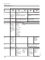
In conjunction with shunt pump for raising the return temperature
L
N
29
29
M
1~
Sensor input aJB is used to control the
Vitotrans 222. Therefore, the shunt
pump must be switched by a separate
temperature controller.
Required code: "4d:2" in category 1
"General".
E Junction box (on site)
F Shunt pump
G Control thermostat,
Part no. Z001 886
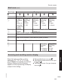
In conjunction with system example 2
5600 634 GB
A separate Vitotronic 200-H must be
used for regulating the Vitotrans 222.
The boiler control unit affects the constant return temperature control
(see coding address "4E" in category 1
"General").
59
Installation
4C:1
4E:2
Preparing for installation
System extension (cont.)
System with flue gas/water heat exchanger
System with flue gas/water heat exchanger, with shunt pump, ID: 4605083
Hydraulic installation scheme
13
WW
3
9
6
2
1
KW
12
5
4
8
7
11
10
Pos.
1
2
3
7
8
9
4
5
6
60
Designation
Boiler I
Shunt pump
Motorised butterfly valve
Boiler II
Shunt pump
Motorised butterfly valve
Vitotrans 300 I
Circulation pump
Motorised butterfly valve
5600 634 GB
Equipment required
Preparing for installation
System extension (cont.)
Designation
Vitotrans 300 II
Circulation pump
Motorised butterfly valve
Low temperature heating circuit
Contactor relay
Wiring diagram
Connection of circulation pump and
motorised butterfly valve for the flue gas/
water heat exchanger.
If the circulation pump power consumption is above 2 A, use a contactor relay.
Note
The shunt pump and motorised butterfly
valve are connected at the relevant
Vitotronic 100.
If plug sÖA1 has already been assigned,
make the connection at extension AM1
(accessory; see page 63).
20 A1
20
N
L
L1
N
K6
qR
M
1~
M
1~
5 / qQ
6 / qW
Code required at every Vitotronic 100
Category
1 "General"
Function
Flue gas/water heat exchanger circulation pump connection at plug sÖA1.
5600 634 GB
4C:3
61
Installation
Pos.
qP
qQ
qW
qE
qR
Preparing for installation
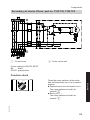
System extension (cont.)
System with flue gas/water heat exchanger, with boiler circuit pump, ID:
4605084
Hydraulic installation scheme
13
WW
6
12
3
9
5
2
1
KW
4
11
8
7
10
Pos.
1
2
3
7
8
9
4
5
6
qP
qQ
qW
62
Designation
Boiler I
Boiler circuit pump
3-way mixing valve
Boiler II
Boiler circuit pump
3-way mixing valve
Vitotrans 300 I
Circulation pump
Motorised butterfly valve
Vitotrans 300 II
Circulation pump
Motorised butterfly valve
5600 634 GB
Equipment required
Preparing for installation
System extension (cont.)
Designation
Low temperature heating circuit
Contactor relay
Wiring diagram
Connection of circulation pump and
motorised butterfly valve for the flue gas/
water heat exchanger.
If the circulation pump power consumption is above 2 A, use a contactor relay.
Note
The boiler circuit pump and 3-way mixing
valve are connected at the relevant
Vitotronic 100.
If plug sÖA1 has already been assigned,
make the connection at extension AM1
(accessory; see page 63).
20 A1
20
N
L
L1
N
K6
qR
M
1~
M
1~
5 / qQ
6 / qW
Code required at every Vitotronic 100
0C:1
4C:3
Category
2 "Boiler"
1 "General"
4d:2
1 "General"
Function
Constant return temperature control.
Flue gas/water heat exchanger circulation pump connection at plug sÖA1.
Boiler circuit pump connection at plug sL.
5600 634 GB
System versions where output sÖA1 is already used as a switching contact
Use extension AM1 A (accessory).
If the circulation pump power consumption is above 2 A, use a contactor relay.
63
Installation
Pos.
qE
qR
Preparing for installation
System extension (cont.)
A
A2
A1
A
[]
[]
f-]
fÖ
sÖsAsK sÖsAsK
L?N
L?N L?N N?L
230 V / 50 Hz
L1 ? N
K6
qR
M
1~
M
1~
5 / qQ
6 / qW
Rated current
4(2) A~
Recommended
Connecting cable H05VV-F3G
0.75 mm2
or
H05RN-F3G
0.75 mm2
Code required at every Vitotronic 100
Category
1 "General"
Function
Function output A1 at extension AM1:
Circulation pump – flue gas/water heat exchanger.
5600 634 GB
33:3
64
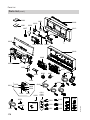
Installation sequence
Overview of electrical connections
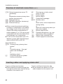
This prevents the wires from drifting into
the adjacent voltage area.
Installation
Note
When connecting plugs aVD, aVH and
sA, bundle the individual wires of the
cables closely to the terminals.
145
145
5600 634 GB
3/2
5
5
17
17
15
9
143
146
A
B
A
B
151
90
41
21
52 A1
20 A1
29
50
40
156
156
Main PCB, low voltage
Boiler water temperature sensor
§
%A Cylinder temperature sensor
%B Cylinder temperature sensor 2 for
primary store system (accessory)
Flow temperature sensor, low loss
)
header
Flue gas temperature sensor
aG
(accessories)
150
aJ A Therm-Control temperature sensor
or
Return temperature sensor T1
(accessory)
65
Installation sequence
Overview of electrical connections (cont.)
aJ B Return temperature sensor T2
(accessory)
or
temperature sensor primary store
system (accessories)
aVD External hook-up
aVG KM BUS subscriber (accessory)
aVH External hook-up
■ When connecting external switching
contacts or components to the safety
low voltage circuit of the control unit,
observe the safety requirements of
safety category II, i.e. 8.0 mm air and
creep paths or 2.0 mm insulation thickness towards 'live' components.
■ For all on-site components (incl. PC/
laptops), ensure safe electrical separation to EN 60 335 or IEC 65.
sL
Shunt pump or boiler circuit
pump (on site)
Power supply
fÖ
Burner stage 1
fA
Central fault message
gÖ
gS A1 Butterfly valve
or
Mixer motor, return temperature
raising facility
or
Motor for 3-way mixing valve, primary store system
Burner stage 2/mod.
lÖ
External connections, e.g. supaBÖ
plementary safety equipment
Safety chain, potential free
aBA
Power supply for accessories
aBH
Main PCB 230 V~
sÖ A1 Primary pump, primary store
system
or
Circulation pump – flue gas/
water heat exchanger
or
Switching output
Circulation pump for cylinder
sA
heating (accessory)
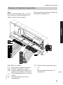
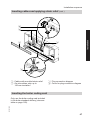
Inserting cables and applying strain relief
Control unit fitted to the boiler side
■ Route cables from below out of the
cable channel into the control unit.
5600 634 GB
Control unit fitted on the boiler
■ Route cables from below through the
front panel of the boiler into the wiring
chamber of the control unit.
66
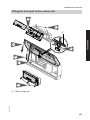
Installation sequence
Inserting cables and applying strain relief (cont.)
A
C
Installation
D
D
B
A Cables with moulded strain relief
B On-site cables; strip up to
100 mm insulation
C Plug connection diagram
D Cover for plug connection diagram
Inserting the boiler coding card
5600 634 GB
Only use the boiler coding card included
in the boiler standard delivery (also see
table on page 169).
67
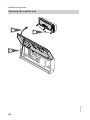
Installation sequence
Inserting the boiler coding card (cont.)
Insert the boiler coding card through the
recess in the cover into slot "X7".
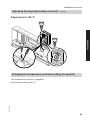
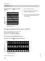
Adjusting the high limit safety cut-out (if required)
5600 634 GB
The high limit safety cut-out is supplied
with a factory setting of 110 °C.
68
Installation sequence
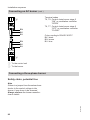
Adjusting the high limit safety cut-out (if… (cont.)
Adjustment to 100 °C
2.
Installation
3.
1.
95
110 1
2
0
°C
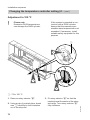
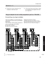
Changing the temperature controller setting (if required)
5600 634 GB
The temperature controller is supplied
with a factory setting of 95 °C.
69
Installation sequence
Changing the temperature controller setting (if… (cont.)
Adjustment to 100 °C
!
Please note
Excessive DHW temperatures
can damage the DHW cylinder.
If the system is operated in conjunction with a DHW cylinder,
ensure that the maximum permissible water temperature is not
exceeded. If necessary, install
suitable safety equipment for this
purpose.
A
2.
1.
3.
1. Remove rotary selector "R".
2. Using a pair of pointed pliers, break
cam A identified in the illustration
out of the stop dial.
70
3. Fit rotary selector "R" so that the
marking lies at the centre of the selected range. Turn rotary selector "R"
fully clockwise.
5600 634 GB
A 75 to 100 °C
Installation sequence
Connecting sensors
2 1
2 1 2 1
2 1 2 1
3
5A 5B
17A 17B
Main PCB, low voltage
§ Boiler water temperature sensor
%A Cylinder temperature sensor
%B Cylinder temperature sensor 2 for
primary store system (accessory)
) Flow temperature sensor, low loss
header
aG Flue gas temperature sensor
(accessories)
2 1 2 1
15
9
aJA Therm-Control temperature sensor
or
Return temperature sensor T1
(accessory)
aJB Temperature sensor T2 (accessory)
or
temperature sensor primary store
system (accessories)
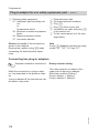
Connecting pumps
Available pump connections
5600 634 GB
sÖ A1 Primary pump, primary store
system
or
Circulation pump – flue gas/
water heat exchanger
Circulation pump for cylinder
sA
heating
Shunt pump or boiler circuit
sL
pump
71
Installation
2 1 2 1
Installation sequence
Connecting pumps (cont.)
Pumps 230 V~
Rated current
4(2) A~
Recommended
connecting cable H05VV-F3G
0.75 mm2
or
H05RN-F3G
0.75 mm2
M A
1~
B
A Pump
B To the control unit
Pumps with power consumption greater than 2 A
N
L
N
D
L N
L
C
B
L N PE
A
D Separate power connection
(observe manufacturer's details)
5600 634 GB
A Pump
B To the control unit
C Contactor
External
ON/OFF
72
Installation sequence
Connecting pumps (cont.)
Pumps 400 V~
N
L
L1 L2 L3 N PE
For switching the contactor
Rated current
4(2) A~
Recommended
connecting cable H05VV-F3G
0.75 mm2
or
H05RN-F3G
0.75 mm2
Installation
C
B
M
A 3~
A Pump
B To the control unit
C Contactor
Connecting servomotors
Available connections
5600 634 GB
gSA1 Motorised butterfly valve
or
Mixer motor for return temperature raising facility
or
Motor for 3-way mixing valve, primary store system
73
Installation sequence
Connecting servomotors (cont.)
Rated voltage
Rated current
Recommended
Connecting
cable
M
1~
52
Runtime
230 V~
max. 0.2 (0.1) A~
H05VV-F4G
0.75 mm2
or
H05RN-F4G
0.75 mm2
5 to 199 s,
adjustable via coding
address "40"
Open
Close
Connecting the central fault message facility
L
N
Rated voltage
230 V~
Rated current
max. 4 (2) A~
Recommended
connecting cable H05VV-F3G
0.75 mm2
or
H05RN-F3G
0.75 mm2
50
Connecting the external safety equipment
74
Note
Plug aBÖ must remain plugged in, even
if no connection is made.
5600 634 GB
Connection via plug aBÖ.
The plug-in adaptor for external safety
equipment (accessory, see chapter
"Components") can be used for connecting several pieces of safety equipment.
Installation sequence
Connecting the external safety equipment (cont.)
Please note
'Live' contacts lead to short circuits or phase failure.
STB
The external connections must
be potential-free.
B
P
C
P
D
P
Installation
!
ON ON
N STB TR TR
A
150
C Maximum pressure limiter
D Further safety equipment
1. Remove jumper "STB" – "STB".
2. Connect the external safety equipment in series to plug aBÖ.
5600 634 GB
A Jumper "STB" – "STB"
B Low water indicator, minimum pressure limiter
75
Installation sequence
Provisional burner operation
STB
EIN EIN
N STB TR TR
Insert jumper "TR" – "ON/TR" at "TR" –
"ON".
The boiler is heated up with burner stage
1 or the lower heating output. Shutdown
takes place via the temperature controller.
A
A Jumper "TR" – "ON/TR"
External blocking – single boiler system
Connection options (floating contact) at:
■ Plug aBÖ
■ Extension EA1 (accessory, see
page 173)
Connection
Please note
'Live' contacts lead to short circuits or phase failure.
The external connection must be
potential-free.
5600 634 GB
!
76
Installation sequence
External blocking – single boiler system (cont.)
Plug aBÖ
Extension EA1
A
DE
[{A
DE
[{S
B
DE
[{D
Installation
A
STB
EIN EIN
N STB TR TR
A Floating contact
B Extension EA1
B
A Floating contact
B Remove jumper "TR" – "ON/TR"
Opening this contact leads to a controlled Closing this contact leads to a controlled
burner shutdown.
burner shutdown. Any connected shunt or
boiler circuit pump is stopped.
Note
Connect only safety shutdown equipment, e.g. temperature limiter, to these
terminals.
!
Please note
The heating system has no frost
protection during blocking.
The boiler is not held at the lower
boiler water temperature.
5600 634 GB
Code
Set "5d", "5E" or "5F" in category 1
"General" to 3 or 4.
77
Installation sequence
External changeover of multi stage/modulating burners
Connection at plug aVH.
!
Contact open: modulating mode
Contact closed: two stage mode
Please note
'Live' contacts lead to short circuits or phase failure.
The external connection must be
potential-free.
A
1 2 3
146
A External changeover
(floating contact)
Code
Set code "02:2" in group 2 "Boiler".
Note
When scanning the burner version, the
address for modulation appears even
after an external changeover (no rewriting).
Single boiler system – connecting an external control unit
■ Codes in category 2 "Boiler":
– "02:1" for two-stage burner
– "02:2" for modulating burner
– "01:1" for single boiler system (delivered condition)
■ The boiler water temperature must be
set to the lower value.
The boiler is held at the required minimum temperature.
78
■ The cylinder temperature controller is
activated when a cylinder temperature
sensor is connected.
■ The high limit safety cut-out settings
and other settings depend on the system equipment level along with safety
equipment to EN 12828 or EN 12953.
5600 634 GB
Settings
Installation sequence
Single boiler system – connecting an… (cont.)
High limit safety cut-out
Temperature controller
Electronic maximum boiler water temperature limit,
coding address "06" in group 2 "Boiler" at the
Vitotronic 100
Maximum temperature of the on-site control unit
110 °C
100 °C
95 °C
100 °C
87 °C
85 °C
90 °C
80 °C
External demand via 0 – 10 V input
0-10V
[{{]
aBJ
12
SÖ P
A
f-]
fÖ
0 - 1 V ≙ "No default set boiler water
temperature"
1V
≙ Set value 10 °C
10 V
≙ Set value 100 °C
Observe coding address "1E" in the
"General" category.
Installation
Connection at 0 – 10 V input at extension EA1 (see page 173).
L?N N?L
230 V~
= 0-10 V
+
External demand via switching contacts
Connection at plug aVD/aVH of the control unit.
The set boiler water temperature is
adjusted via code "9b" in category
1"General".
5600 634 GB
Two-stage burner
A, B and C are floating contacts of
the higher control unit.
79
Installation sequence
Single boiler system – connecting an… (cont.)
A
B
C
1 2 3
1 2 3
143
146
A Burner stage 1 "ON"
B Burner stage 2 "ON"
C External load-dependent starting
External burner start – burner stage 1
Contact at terminals "2" and "3" of plug
aVD
■ Contact closed:
Both burner stages are switched ON.
The boiler water temperature is limited
by the electronic maximum temperature limiter, if it is set below that of
mechanical control thermostat "R".
Burner stage 2 is switched OFF 2 K
sooner.
■ Contact open:
Burner stages 1 and 2 are switched
OFF.
External starting subject to load
The burner is started, subject to load,
when the zero volt contact across terminals "2" and "3" at plug-in connector
aVH closes.
The boiler will be constantly operated at
the set temperature.
The boiler water temperature is limited
via the maximum set boiler water temperature or via the mechanical control
thermostat.
The set value is adjusted via code "9b".
5600 634 GB
Contact at terminals "1" and "2" of plug
aVD:
■ Contact closed:
Burner stage 1 is switched on.
Burner stage 2 is switched ON only for
maintaining the minimum temperature.
The boiler water temperature is limited
by the electronic maximum temperature limiter, if that is set below that of
mechanical temperature controller R.
■ Contact open:
Burner stage 1 is switched off.
External burner start – burner stage 1
and 2
80
Installation sequence
Single boiler system – connecting an… (cont.)
Low temperature boiler with modulating burner (on-site modulation controller)
Burner connection:
Installation
■ Connect plug fA of Vitotronic 100 to
the burner.
■ Plug lÖ from the Vitotronic 100 via
modulation controller (on site) to plug
lÖ on the burner.
■ Set the minimum temperature at the
higher control unit with the modulation
controller 5 K higher than the lower
boiler water temperature.
A
41
90
143
1 2 3
BU
BK
BN
C
D
B
BN
41
90
BK
BU
5600 634 GB
E
A Plug to the control unit
B Burner with base load "ON"
81
Installation sequence
Single boiler system – connecting an… (cont.)
C Reduce burner output (modulation
controller)
D Increase burner output (modulation
controller)
E Plug to the burner
Colour coding to DIN IEC 60757
BK black
BN brown
BU blue
External burner start – base load
Contact at terminals "1" and "2" of plug
aVD
■ Contact closed:
The burner is started with base load.
To maintain the minimum temperature, the burner is switched to full load
via the Vitotronic 100.
The boiler water temperature is limited
by the electronic maximum temperature limiter, if that is set below that of
mechanical temperature controller R.
■ Contact open:
The burner is switched OFF.
Vitocrossal with modulating burner (on-site modulation controller)
Burner connection:
5600 634 GB
■ Connect plug fA of Vitotronic 100 to
the burner.
■ Plug lÖ of the Vitotronic 100 remains
unallocated.
■ Connect plug lÖ of the burner to the
on-site modulation controller.
82
Installation sequence
Single boiler system – connecting an… (cont.)
A
143
L
C
N T1 T2 S3 B4
1 2 3
41
B
B4 S3 T2 T1 N
L
90
T6 T7T8
Installation
D
BN
BK
BU
41
E
A Plug to the control unit
B Burner with base load "ON"
C Reduce burner output (modulation
controller)
D Increase burner output (modulation
controller)
E Plug to the burner
Colour coding to DIN IEC 60757
BK black
BN brown
BU blue
External burner start – base load
5600 634 GB
Contact at terminals "1" and "2" of plug
aVD
■ Contact closed:
The burner is started with base load.
An external modulation controller regulates the load-dependent modulation.
83
Installation sequence
Single boiler system – connecting an… (cont.)
The boiler water temperature is limited
by the electronic maximum temperature limiter, if that is set below that of
mechanical temperature controller R.
■ Contact open:
The burner is switched OFF.
Multi boiler system – connecting an external control unit
Settings
■ Codes in category 2 "Boiler":
– "02:1" for two-stage burner
– "02:2" for modulating burner
– "01:3" for multi boiler system with
on-site cascade control (third party
control unit)
– "01:2" with on-site cascade control
(third party control unit) via LON
■ The cascade and cylinder control must
be provided by the higher third party
control unit.
!
Please note
A boiler enable contact is
essential to prevent boiler
damage.
This contact must always be
closed on the lead boiler.
High limit safety cut-out
Temperature controller
Electronic maximum boiler water temperature limit,
coding address "06" in group 2 "Boiler" at the
Vitotronic 100
Maximum temperature of the on-site control unit
84
110 °C
100 °C
95 °C
100 °C
87 °C
85 °C
90 °C
80 °C
5600 634 GB
■ The high limit safety cut-out settings
and other settings depend on the system equipment level along with safety
equipment to EN 12828 or EN 12953.
Installation sequence
Multi boiler system – connecting an… (cont.)
External demand via 0 – 10 V input
Connection at 0 – 10 V input at extension EA1 on each Vitotronic 100 (accessory, see page 173).
aBJ
12
SÖ P
A
f-]
fÖ
L?N N?L
230 V~
= 0-10 V
+
Enable boiler without an additional enable contact
0 to 1 V
■ Boiler blocked.
■ Butterfly valve closed.
■ Boiler circuit pump or shunt pump
OFF.
1 to 10 V
■ Boiler water temperature default
1 V ≙ Set value 10 °C
10 V ≙ Set value 100 °C
Observe coding address "1E" in the
"General" category.
■ Boiler enabled and held at its minimum
temperature.
■ Butterfly valve open.
■ Boiler circuit pump or shunt pump enabled.
Note
Only for low temperature boilers:
On the lead boiler, the voltage must be
higher than 1 V.
5600 634 GB
Enable boiler with an additional enable contact
0 - 1 V ≙ "No default set boiler water
temperature"
1V
≙ Set value 10 °C
10 V
≙ Set value 100 °C
Observe coding address "1E" in the
"General" category.
85
Installation
0-10V
[{{]
Installation sequence
Multi boiler system – connecting an… (cont.)
Make connection at plug aVH.
A
1 2 3
Note
This contact must always be closed on
the lead boiler.
146
A Boiler enable
(floating contact)
Contact
A
Closed
Boiler enabled and held at its minimum temperature. The butterfly
valve opens.
Open
The butterfly valve is closed after
approx. 5 min. External burner start
not possible.
External demand via switching contacts
Connection at plug aVD/aVH of the control unit.
The set boiler water temperature is
adjusted via code "9b" in category
1"General".
A
B
Two-stage burner
C
A, B and C are floating contacts of
the higher control unit.
1 2 3
1 2 3
143
146
5600 634 GB
A Burner stage 1 "ON"
B Burner stage 2 "ON"
C Boiler enable
Butterfly valve "Open" or "Close"
86
Installation sequence
External burner start – burner stage 1
Enable boiler, butterfly valve
Contact at terminals "1" and "2" of plug
aVD:
■ Contact closed:
Burner stage 1 is switched on.
Burner stage 2 is switched ON only for
maintaining the minimum temperature.
The boiler water temperature is limited
by the electronic maximum temperature limiter, if that is set below that of
mechanical temperature controller R.
■ Contact open:
Burner stage 1 is switched off.
Contact at terminals "2" and "3" of plug
aVH
■ Contact closed:
– Vitocrossal:
The butterfly valve opens.
– Low temperature boiler:
Initially, the preheat function for lag
boilers is activated.
After the preheat function has
expired, the minimum boiler water
temperature will be maintained and
the burner stages can be controlled
externally.
The butterfly valve opens.
■ Contact open:
The butterfly valve is closed after
approx. 5 min.
Burner stages cannot be switched ON
externally; a minimum temperature will
not be maintained.
External burner start – burner stage 1
and 2
5600 634 GB
Contact at terminals "2" and "3" of plug
aVD
■ Contact closed:
Both burner stages are switched ON.
The boiler water temperature is limited
by the electronic maximum temperature limiter, if it is set below that of
mechanical control thermostat "R".
Burner stage 2 is switched OFF 2 K
sooner.
■ Contact open:
Burner stages 1 and 2 are switched
OFF.
87
Installation
Multi boiler system – connecting an… (cont.)
Installation sequence
Multi boiler system – connecting an… (cont.)
Low temperature boiler with modulating burner (on-site modulation controller)
Burner connection:
■ Connect plug fA of Vitotronic 100 to
the burner.
■ Plug lÖ from the Vitotronic 100 via
modulation controller (on site) to plug
lÖ on the burner.
■ Via external demand aVD, the on-site
modulation controller starts the burner
with base load.
A
41
90
L
T6T7T8
146
N T1 T2 S3 B4
BU
BK
BN
1 2 3
143
1 2 3
B
D
E
C
STB
L1
TR
N
BZ
Fault H1
N
PE
L1
BN
41
T1 T2 S3 B4
90
T6 T7 T8
BK
BU
A Plug to the control unit
88
B Boiler enable
Butterfly valve "Open" or "Close"
5600 634 GB
F
Installation sequence
C Burner with base load "ON"
D Reduce burner output (modulation
controller)
E Increase burner output (modulation
controller)
F Plug to the burner
Colour coding to DIN IEC 60757
BK black
BN brown
BU blue
Enable boiler, butterfly valve
External burner start – base load
Contact at terminals "1" and "2" of plug
aVD
■ Contact closed:
The burner is started with base load.
To maintain the minimum temperature, the burner is switched to full load
via the Vitotronic 100.
The boiler water temperature is limited
by the electronic maximum temperature limiter, if that is set below that of
mechanical temperature controller R.
■ Contact open:
The burner is switched OFF.
Contact at terminals "2" and "3" of plug
aVH
■ Contact closed:
Initially, the preheat function for lag
boilers is activated.
After the preheat function has expired,
the minimum boiler water temperature
is maintained and the burner is controlled by the on-site modulation controller.
■ Contact open:
The butterfly valve is closed after
approx. 5 min.
The burner cannot be switched ON
externally; a minimum temperature will
not be maintained.
Vitocrossal with modulating burner (on-site modulation controller)
Burner connection:
5600 634 GB
■ Connect plug fA of Vitotronic 100 to
the burner.
■ Plug lÖ of the Vitotronic 100 remains
unallocated.
■ Via external demand aVH, the on-site
modulation controller starts the burner
with base load.
89
Installation
Multi boiler system – connecting an… (cont.)
Installation sequence
Multi boiler system – connecting an… (cont.)
A
L
C
143
146
1 2 3
1 2 3
N T1 T2 S3 B4
41
D
B
C
B4 S3 T2 T1 N
L
90
T6 T7T8
BN
BK
BU
41
E
A Plug to the control unit
B Boiler enable
Butterfly valve "Open" or "Close"
C Burner with base load "ON"
D Reduce burner output (modulation
controller)
E Increase burner output (modulation
controller)
F Plug to the burner
Colour coding to DIN IEC 60757
BK black
BN brown
BU blue
External burner start – base load
5600 634 GB
Contact at terminals "1" and "2" of plug
aVD
■ Contact closed:
The burner is started with base load.
An external modulation controller regulates the load-dependent modulation.
90
Installation sequence
Multi boiler system – connecting an… (cont.)
Enable boiler, butterfly valve
Contact at terminals "2" and "3" of plug
aVH
■ Contact closed:
The butterfly valve opens.
■ Contact open:
The butterfly valve is closed after
approx. 5 min.
The burner cannot be switched ON
externally; a minimum temperature will
not be maintained.
Hooking up on-site control devices via LON
A
B
C
1 2 3
1 2 3
143
146
A Boiler blocking
B Start boiler as the last one in the
boiler sequence
C External changeover of stepped/
modulating burners
Boiler blocking
Contact at terminals "1" and "2" of plug
aVD:
■ Contact closed:
The boiler is blocked and has been
removed from the boiler sequence.
The butterfly valve or the 3-way mixer
for constant return temperature raising, the shunt pump or the boiler circuit
pump are switched OFF.
The other boilers provide the required
heating.
!
Please note
If all boilers are blocked or
there is no other boiler ready
for operation,
then there will be no frost protection for the heating system.
5600 634 GB
■ Contact open:
The boiler is reinstated into the current
boiler sequence.
91
Installation
The boiler water temperature is limited
by the electronic maximum temperature limiter, if that is set below that of
mechanical temperature controller R.
■ Contact open:
The burner is switched OFF.
Installation sequence
Multi boiler system – connecting an… (cont.)
Start boiler as the last one in the
boiler sequence
Contact at terminals "2" and "3" of plug
aVD:
■ Contact closed:
The boiler is started as the last one in
the boiler sequence.
This boiler is started if the other boilers
in the heating system cannot provide
sufficient heat.
■ Contact open:
The boiler is reinstated into the current
boiler sequence.
Connecting an AC burner
Pressure-jet oil/gas burners
Max. current consumption 6 (3) A.
5600 634 GB
The burner cables are included in the
standard boiler delivery.
Connect the burner in accordance with
DIN 4791 [or local regulations].
92
Installation sequence
Terminal codes
L1
Phase via high limit safety cutout to the burner
PE
Earth conductor to burner
N
Neutral conductor to burner
T1, T2 Control chain
S3
Connection for burner fault
B4
Connection for hours run meter
Signal pass direction:
Control unit → burner
Signal pass direction:
Burner → control unit
41
L1
TR
N
BZ
Störung H1
N
PE
L1
N T1 T2 S3 B4
STB
L
41
T1 T2 S3 B4
A To the control unit
B To the burner
Equipment codes
High limit safety cut-out Control unit
high limit
safety cut-out
TR
Control unit
temperature
controller
H1
Burner fault
signal
BZ
Hours run
meter
5600 634 GB
Burner without plug
Install the mating plug from Viessmann
or from the burner manufacturer; connect the burner cable.
93
Installation
Connecting an AC burner (cont.)
Installation sequence
Connecting an AC burner (cont.)
90
T6 T7T8
BN
BK
BU
Terminal codes
T6, T8 Control chain burner stage 2
"ON" or modulation controller
"OPEN"
T6, T7 Control chain burner stage 2
"OFF" or modulation controller
"CLOSE"
Signal pass direction:
Control unit → burner
Signal pass direction:
Burner → control unit
Colour coding to DIN IEC 60757
BK black
BN brown
BU blue
A To the control unit
B To the burner
Viessmann Unit burner
Max. current consumption 6 (3) A.
5600 634 GB
The burner cables are included in the
Vitocrossal standard delivery.
94
Installation sequence
A
L
N T1 T2 S3 B4
41
B4 S3 T2 T1 N
Terminal codes
L1
Phase via high limit safety cutout to the burner
PE
Earth conductor to burner
N
Neutral conductor to burner
T1, T2 Control chain
S3
Connection for burner fault
B4
Connection for hours run meter
Signal pass direction:
Control unit → burner
Signal pass direction:
Burner → control unit
L
41
B
5600 634 GB
A To the control unit
B To the burner
95
Installation
Connecting an AC burner (cont.)
Installation sequence
Connecting an AC burner (cont.)
A
90
T6 T7T8
BN
BK
BU
BN
BK
BU
Terminal codes
T6, T8 Control chain burner stage 2
"ON" or modulation controller
"OPEN"
T6, T7 Control chain burner stage 2
"OFF" or modulation controller
"CLOSE"
Colour coding to DIN IEC 60757
BK black
BN brown
BU blue
90
T6 T7T8
B
A To the control unit
B To the burner
Connecting a three-phase burner
Safety chain, potential free
5600 634 GB
Note
If there is a jumper from the external conductor to the control voltage in the
burner, it may have to be removed.
Always observe the burner manufacturer's details.
96
Installation sequence
Connecting a three-phase burner (cont.)
F2
TR
K1
A
Installation
T6 T7 T8
a
B
C
A
B
C
D
E
F
E
GH K
F
Control unit
Main contactor (on site)
Three-phase burner
Three-phase burner power supply
Main contactor control
Safety chain (high limit safety cutout), potential-free
Control chain stage 1/base load
Burner fault message
Hours run meter stage 1
Base load/full load
L
fÖ
Control unit power supply connection
fA Burner, stage 1
lÖ Burner, stage 2
aBÖ Plug for external connections
a External safety equipment;
remove jumper when connecting
aBA Safety chain, potential-free,
remove jumper when making this
connection
5600 634 GB
G
H
K
L
D
97
Installation sequence
Connecting a three-phase burner (cont.)
Safety chain not potential-free
Note
If there is a jumper from the external conductor to the control voltage in the
burner, it may have to be removed.
Always observe the burner manufacturer's details.
F2
TR
K1
A
T6 T7 T8
a
B
C
D
FG H
K
E
98
Control unit
Main contactor (on site)
Three-phase burner
Three-phase burner power supply
Main contactor control
Control chain stage 1/base load
Burner fault message
Hours run meter stage 1
Base load/full load
fÖ
Control unit power supply connection
fA Burner, stage 1
lÖ Burner, stage 2
aBÖ Plug for external connections
a External safety equipment;
remove jumper when connecting
aBA Safety chain (STB)
5600 634 GB
A
B
C
D
E
F
G
H
K
Installation sequence
Power supply
Regulations
Carry out the power supply connection
and all earthing measures (i.e. RCD circuit) in accordance with IEC 60364, the
requirements of your local power supply
utility, and VDE or national regulations.
Protect the power cable to the control
unit with an appropriate fuse/MCB.
Recommended power cable
3-core cable selected from the following
options:
■ H05VV-F3G 1.5 mm2
■ H05RN-F3G 1.5 mm2
5600 634 GB
For oil and gas combustion equipment
over 100 kW, according to the Sample
Combustion Ordinance "FeuVO", an
"emergency shutdown" must be installed
on site outside the installation room. The
national combustion equipment ordinance for your local region must be
observed. For combustion equipment to
EN 50156-1, the "emergency shutdown" installed on site must comply with
the requirements of EN 50156-1.
Install the "emergency shutdown" outside the installation room; it must be able
to separate all non-earthed conductors
simultaneously with a gap of 3 mm at
least.
We additionally recommend installing an
AC/DC-sensitive RCD (RCD class B
) for DC (fault) currents that can occur
with energy-efficient equipment.
99
Installation
Directives
Installation sequence
Power supply (cont.)
1. Check whether the power cable to the
control unit has appropriate fuse protection.
L1
PE
N
BU
GNYE
BN
2. Connect the power cable at the junction box and plug fÖ (on-site).
N
L
40
A
B
C
D
Danger
Incorrect core allocation can
cause severe injury and can
damage the appliance.
Take care not to interchange
wires "L1" and "N":
L1 BN (brown)
N BU (blue)
PE GNYE (green/yellow)
3. Insert plug fÖ into the control unit.
Power supply 230 V~
Fuse
Mains isolator, two-pole (on-site)
Junction box (on site)
Power supply in conjunction with Vitocrossal, type CT2
5600 634 GB
The power supply is connected at the
boiler burner control unit.
100
Installation sequence
Fitting the front part of the control unit
2.
1.
Installation
A
6.
4.
3.
5.
7.
5600 634 GB
A Cable locking tab
101
Installation sequence
Opening the control unit
2.
1.
5600 634 GB
3.
102
Commissioning
Testing the high limit safety cut-out
The minimum circulation volume should
be 10 % of the circulation volume at rated
load.
Reduce the heat consumption as far as
possible.
1. Hold down the "TEST" key until the
burner has shut down:
Thermostat is bridged. The high limit
safety cut-out must shut down the
burner at the latest when the safety
temperature has been reached.
2. Release the "TEST" key.
3. Wait until the boiler water temperature has dropped approx. 15 to 20 K
below the selected safety temperature.
4. Reset the high limit safety cut-out by
pressing reset button.
Operating instructions
Matching the coding addresses to the system version
Check and poss. adjust all addresses in
Code 1.
Category
2 "Boiler"
2 "Boiler"
1 "General"
1 "General"
1 "General"
1 "General"
1 "General"
Function
Return temperature control
Therm-Control
Function plug sÖ
Function plug sL
Function plug gS
Viessmann system number
Monitoring LON subscribers
5600 634 GB
Service
"0C"
"0d"
"4C"
"4d"
"4E"
"98"
"9C"
Check the following coding addresses
and adjust accordingly in Code 2:
103
Commissioning
Matching the coding addresses to the system… (cont.)
Matching the control unit to the two-stage burner
Matching coding addresses according to the burner used
Address Meaning
Setting
03:...
Fuel
Gas operation: 0 (delivered condition)
Oil operation: 1 (irreversible)
08:...
Units and tens of the maximum
Example: Max. burner output:
burner output
225 kW – select: 25
Note
Values up to and including 199 kW
can be entered directly.
09:...
0A:...
Hundreds of the maximum burner
output
Ratio of output burner stage 1 to
maximum burner output in percent
Example: Max. burner output: 225
kW – select: 2
Example: Output burner stage 1
135 kW
Max. burner output: 225 kW
(135 kW: 225 kW) ∙ 100 % = 60 %
Matching the control unit to the modulating burner
Note
The burner must be fully adjusted. To
achieve a wide modulating range, set the
minimum output as low as possible (take
the chimney and flue system into
account).
Note
Values up to and including 199 kW
can be entered directly.
104
5600 634 GB
Matching coding addresses according to the burner used
Address Meaning
Setting
03:...
Fuel
Gas operation: 0 (delivered condition)
Oil operation: 1 (irreversible)
08:...
Units and tens of the maximum
Example: Max. burner output:
burner output
225 kW – select: 25
Commissioning
Matching the coding addresses to the system… (cont.)
Address
09:...
15:...
Meaning
Hundreds of the maximum burner
output
Modulation range runtime
0A:...
Ratio of output base load to maximum burner output in percent
05:...
Ratio of partial output at ⅓ of the
servomotor runtime to maximum
burner output in percent
Setting
Example: Max. burner output: 225
kW – select: 2
Calculate servomotor runtime (s)
between base load and max. burner
output
Example: Output burner stage 1
135 kW
Max. burner output: 225 kW
(135 kW: 225 kW) ∙ 100 % = 60 %
Example: Partial output 171 kW
Max. burner output: 225 kW
(171 kW: 225 kW) ∙ 100 % = 76 %
Checking actuators and sensors
Testing relays
1. Press OK and
simultaneously for
approx. 4 s.
flashes on the display.
select
and confirm with
5600 634 GB
Service
2. With
OK.
3. Select required actuator with / (see
following table).
The display shows the number for the
activated actuator and "ON".
105
Commissioning
Checking actuators and sensors (cont.)
The following actuators (relay outputs) can be switched subject to system
equipment level:
Display
Explanation
0
All actuators are switched off
1
Burner ON or burner stage 1 ON or modulation controller ramps
up (modul. burner)
2
Burner stages 1 and 2 ON or modulation controller neutral
(modul. burner)
3
Modulation controller ramps down (modul. burner).
5
Output sÖ On
6
Output sL On
7
Output gS Open
8
Output gS Neutral
9
Output gS Close
10
Output circulation pump for cylinder heating sA ON
11
Output central fault message gÖ ON
15
Solar circuit pump output sF at solar control module SM1 enabled
16
Solar circuit pump output sF at solar control module SM1
switched to minimum speed
17
Solar circuit pump output sF at solar control module SM1
switched to maximum speed
18
Output sS at solar control module SM1 enabled
19
Contact P - S on plug aBJ for extension EA1 closed
20
Output A1 at extension AM1 enabled
21
Output A2 at extension AM1 enabled
Note
During burner operation, the connected
pumps are started.
Checking sensors
Actual temperatures can be scanned in
the "i" menu.
Operating instructions
The LON communication module
(accessories) must be plugged in (see
parts list).
106
Note
The data transfer via LON can take several minutes.
5600 634 GB
Integrating a control unit into the LON
Commissioning
Integrating a control unit into the LON (cont.)
Multi boiler system with Vitotronic 100 and Vitocom 300
Set the LON subscriber numbers and
further functions via code 2.
Note
In the same LON system, the same number cannot be allocated twice.
Only one Vitotronic may be programmed as fault manager.
Carrying out a LON subscriber check
Communication with the LON subscribers connected to the fault manager is
tested by means of a subscriber check.
Requirements:
■ The control unit must be programmed
as fault manager (code "79:1").
■ The LON subscriber number must be
programmed in all control units.
■ The LON subscriber list in the fault
manager must be up to date.
1. Press OK and
approx. 4 s.
3. Select subscriber with / .
4. Activate the check with OK.
The subscriber address flashes.
■ Check OK: subscriber address is
shown constantly.
■ Check not OK: also appears.
Successfully tested subscribers are
indicated in the list with ":"
5. Exiting the subscriber check: Press
.
simultaneously for
Service
2. Press to select 7.
A list of the known LON subscribers
is displayed.
Example: 01 - - 99
Entering a service PIN for LON subscribers
Integration of the Vitotronic 100 into a
higher LON system, e.g. in conjunction
with a third party control unit.
The LON subscriber is identified with the
service PIN.
2. Press to select 6.
"PIN" is displayed.
3. Enable PIN with OK.
5600 634 GB
4. Exiting the input function: Press
1. Press OK and
approx. 4 s.
.
simultaneously for
107
Commissioning
Entering a PIN code for Vitocom 100
The PIN code of a connected Vitocom
100 can be entered at the Vitotronic
100.
Vitocom 100 installation instructions
1. Press OK and
approx. 4 s.
simultaneously for
2. Press to select 8.
"00 00" is displayed for the entry of
the PIN code and the number of
remaining entry attempts.
3. Select the position for the entry with
/ .
4. Select the relevant figures with / .
5. Confirm the PIN code with OK.
The entered PIN code is checked (figures flashing).
If the PIN code entered is correct,
"FrEE" is displayed and the entry is
automatically left.
.
5600 634 GB
6. Exiting the input function: Press
108
Service scans
Calling up the service level
1. Press OK and
simultaneously for
approx. 4 s.
flashes on the display.
2. Select required function. See the following pages.
Leaving the service level
1. Press
to select 9.
3. Confirm with OK.
Note
The service level is automatically exited after 30 minutes.
2. Confirm with OK.
"OFF" flashes.
Scanning operating data
Operating data can be scanned in the
"i" menu.
Operating instructions
Brief scan
1. Press OK and
simultaneously for
approx. 4 s.
flashes on the display.
3. Select the required scan with / . For
example, "b" for "Boiler coding card"
(see following table):
2. Confirm with OK.
4. Confirm selected scan with OK.
5600 634 GB
0
2
3
4
5
System
scheme
Service
For explanations of individual scans, see the following table:
Brief scan
Display
Software version
Control unit
Software
version
Programming unit
Maximum flue gas temperature
Set boiler water temperature
Common demand temperature
Set cylinder temperature
109
Service scans
Brief scan (cont.)
6
7
8
9
b
L
E
1
E
3
F
2
110
Display
Number of KM BUS sub- Number of LON subscribscribers
ers
SNVT con- Software version commu- Software version LON
figuration
nication coprocessor
module
0:Auto
1:Tool
Subnet address/system
Node address
no.
Burner type
Appliance type
Boiler coding card
Burner:
Butterfly
Output reduction in %
0: OFF
valve:
0: OFF
1: Burner
0: OFF
stage 1/
1: Preheatbase load
ing
2: Burner
2: Control
stage 2/full Close
load
3: Control
4: Control
Open
5: Open
6: Run-on
Software
Software
version
version
solar concascade
trol modmodule
ule, type
SM1
Software version
plug-in adaptor for external safety equipment
Extension AM1
Software
Output A1
Output A1 Output A2
Output A2
version
configuraswitching
configuraswitching
tion
state
tion
state
(value corre- 0: OFF
(value cor- 0: OFF
sponds to
1: ON
responds to 1: ON
code 33 setcode 34 setting)
ting)
5600 634 GB
Brief scan
Service scans
Brief scan (cont.)
Brief scan
F
3
F
4
F
5
F
6
F
7
F
8
Display
Extension EA1
Output 157 Output 157
Input DE1
Input DE2
configura- switching
switching
switching
tion
state
state
state
(value cor- 0: OFF
0: open
0: open
responds
1: ON
1: closed
1: closed
to code 5C
setting)
Software
External hook-up 0 - 10 V
version
Display in %
Solar control module SM1
Stagnation time of the solar thermal system in h
Input DE3
switching
state
0: open
1: closed
Night DHW circulation, solar thermal system (number)
Monitoring of differential temperature, solar thermal system
Reheating
suppression
0: disabled
1: enabled
Output 22
switching
state
0: OFF
1: ON
■ The specified hours run and .
■ The defaulted interval with clock symbol and .
■ The defaulted max. flue gas temperature and .
5600 634 GB
When the limits specified in coding
addresses "21", "23" or "1F" in category 2 "Boiler" are reached, the red fault
indicator flashes and the following
appears on the programming unit display
(subject to the setting):
111
Service
Scanning and resetting service display
Service scans
Scanning and resetting service display (cont.)
a
150
°C
Acknowledging and resetting service
Press OK to acknowledge a service
message.
Note
An acknowledged service message that
was not reset reappears after 7 days.
After a service has been carried out (resetting service)
Reset code "24:1" to "24:0" in category
2 "Boiler".
5600 634 GB
Note
The selected service parameters for
hours run and time interval restart at 0.
112
Troubleshooting
Fault display
In the event of a fault, the red fault display flashes at the control unit. On the
programming unit display, the 2-digit
fault code and flash.
Output gÖ (central fault message) is
switched ON.
Other current faults can be displayed
with / . For an explanation of the fault
codes, see the following pages.
ã
1
50
Example: Fault code "50"
Acknowledge fault
Press OK; the standard display is shown
again.
A fault message facility, if connected, will
be switched off.
If an acknowledged fault is not remedied,
the fault message will be re-displayed
the following day and the fault message
facility restarted.
Calling up acknowledged faults
Press OK for approx. 4 s.
The 10 most recent faults (including
resolved ones) can be scanned.
Calling up fault codes from the fault memory (fault history)
The 10 most recent faults (including
those remedied) are saved and can be
called up.
Faults are sorted by date.
3. Select fault messages with / .
Service
simultaneously for
5600 634 GB
1. Press OK and
approx. 4 s.
2. Select with and activate fault history with OK.
113
Troubleshooting
Fault display (cont.)
Fault codes
Displayed
fault code
0F
30
■ With DHW cylinder:
Circulation pump
for cylinder heating
on; boiler is maintained at set cylinder temperature.
■ Without DHW cylinder:
Boiler is regulated
by the temperature
controller.
■ With DHW cylinder:
Circulation pump
for cylinder heating
on; boiler is maintained at set cylinder temperature.
■ Without DHW cylinder:
Boiler is regulated
by the temperature
controller.
Measures
Service required
Note
After servicing, set code
"24:0".
Short circuit, boiler Check the boiler water
water temperature temperature sensor (see
sensor.
page 169).
Lead break, boiler
water temperature
sensor.
Check the boiler water
temperature sensor (see
page 169).
5600 634 GB
38
System characteris- Cause
tics
Control mode.
Service
"0F" is only displayed in the fault
history.
114
Troubleshooting
Fault display (cont.)
51
52
Cylinder primary
pump "ON":
Set DHW temperature = Set boiler water
temperature
Priority control is cancelled or
With primary store
system:
Cylinder heating is
started and stopped
via cylinder temperature sensor 2.
Cause
Measures
Short circuit, cylinder temperature
sensor 1.
Check the cylinder temperature sensor (see
page 169).
Short circuit, cylinder temperature
sensor 2.
Check the cylinder temperature sensor (see
page 169).
Short circuit, flow
temperature sensor.
Lead break, cylinder temperature
sensor 1.
Check the flow temperature sensor (see
page 169).
Check the cylinder temperature sensor (see
page 169).
5600 634 GB
58
System characteristics
Cylinder primary
pump "ON":
Set DHW temperature = Set boiler water
temperature
Priority control is cancelled or
With primary store
system:
Cylinder heating is
started and stopped
via cylinder temperature sensor 2.
With primary store
system:
Cylinder heating is
started and stopped
via cylinder temperature sensor 1.
Control mode.
Service
Displayed
fault code
50
115
Troubleshooting
Fault display (cont.)
Displayed
fault code
59
5A
60
68
70
Cause
Measures
Lead break, cylinder temperature
sensor 2.
Check the cylinder temperature sensor (see
page 169).
Lead break, flow
temperature sensor.
Short circuit, temperature sensor
aJA.
Check the flow temperature sensor (see
page 169).
Check temperature sensor (see page 169).
Boiler with maximum
temperature, no output reduction, mixing
valve return temperature control "Open".
Boiler with maximum Lead break, temtemperature, no out- perature sensor
put reduction, mixing aJA.
valve return temperature control "Open".
Shunt pump constantly "ON".
With primary store
system:
Mixer primary circuit
"Close"; no DHW
heating.
Shunt pump constantly "ON".
With primary store
system:
Mixer primary circuit
"Close"; no DHW
heating.
Short circuit, temperature sensor
aJB.
Lead break, temperature sensor
aJB.
Check temperature sensor (see page 169).
Without temperature sensor:
Set code "4A:0" in group 1
"General".
Check temperature sensor (see page 169).
Check temperature sensor (see page 169).
Without temperature sensor:
Set code "4b:0" in group 1
"General".
5600 634 GB
78
System characteristics
With primary store
system:
Cylinder heating is
started and stopped
by cylinder temperature sensor 1.
Control mode.
116
Troubleshooting
Fault display (cont.)
91
92
Measures
Control mode.
Short circuit, temperature sensor
aÖ,
Connection at the
solar control module.
Check temperature sensor aÖ.
Short circuit, collector temperature
sensor,
Connection of temperature sensor
& at solar control
module or sensor
at S1 of the
Vitosolic.
Short circuit, temperature sensor,
connection at S3 of
the Vitosolic.
Check solar control unit
sensor.
No solar DHW heating.
Control mode.
Check temperature sensor /.
Solar control module installation and
service instructions
Solar control module installation and
service instructions
Solar control unit
installation and
service instructions
Check solar control unit
sensor.
Solar control unit
installation and
service instructions
5600 634 GB
93
System characteris- Cause
tics
Control mode.
Short circuit, temperature sensor /,
Connection at the
solar control module.
117
Service
Displayed
fault code
90
Troubleshooting
Fault display (cont.)
98
99
9A
9b
118
System characteris- Cause
tics
No solar DHW heat- Short circuit, cylining.
der temperature
sensor, connection
of temperature
sensor % at solar
control module or
sensor at S2 of the
Vitosolic.
Control mode.
Lead break, temperature sensor /, connection
to the solar control
module.
Measures
Control mode.
Lead break, temperature sensor
aÖ, connection to
the solar control
module.
Check temperature sensor aÖ.
Lead break, collector temperature
sensor, connection
of temperature
sensor & at solar
control module or
sensor at S1 of the
Vitosolic.
Lead break, temperature sensor,
connection of sensor at S3 of the
Vitosolic.
Check solar control unit
sensor.
No solar DHW heating.
No solar DHW heating.
Check solar control unit
sensor.
Solar control unit
installation and
service instructions
Check temperature sensor /.
Solar control module installation and
service instructions
Solar control module installation and
service instructions
Solar control unit
installation and
service instructions
Check solar control unit
sensor.
Solar control unit
installation and
service instructions
5600 634 GB
Displayed
fault code
94
Troubleshooting
Fault display (cont.)
Displayed
fault code
9C
9E
System characteris- Cause
tics
Control mode.
Lead break, cylinder temperature
sensor, connection
of temperature
sensor % at solar
control module or
sensor at S2 of the
Vitosolic.
Control mode.
No flow rate in
solar circuit or flow
rate too low, or
temperature limiter
has responded.
Measures
Check solar control unit
sensor.
Solar control unit
installation and
service instructions
Check solar circuit pump
and solar circuit.
Acknowledge fault message.
Solar control unit
installation and
service instructions
Control mode.
Boiler cools down.
A1
Boiler cools down.
Check solar control unit.
Solar control unit
installation and
service instructions
Check safety equipment,
and reset if required.
Check safety equipment,
and reset if required.
5600 634 GB
A0
Solar control module or Vitosolic
fault.
Displayed if a fault
occurs at these
appliances that
has no fault code in
the Vitotronic.
Fault, safety equipment at "X7" of
plug-in adaptor 2
for external safety
equipment.
Fault, safety equipment at "X3" of
plug-in adaptor 2
for external safety
equipment.
Service
9F
119
Troubleshooting
Fault display (cont.)
Displayed
fault code
A2
A3
AA
Ab
Measures
Check safety equipment,
and reset if required.
Check safety equipment,
and reset if required.
Insert plug aJA.
For Vitocrossal, code "0d:
0" in group 2 "Boiler"
must be selected.
Insert plug aJB and check
codes.
Insert plug aJA and check
codes.
5600 634 GB
AC
System characteris- Cause
tics
Boiler cools down.
Fault, safety equipment at "X2" of
plug-in adaptor 2
for external safety
equipment.
Boiler cools down.
Fault, safety equipment at "X1" of
plug-in adaptor 2
for external safety
equipment.
Control mode.
Therm-Control
configuration fault:
Plug aJA not plugged in.
Control operation;
Primary store sysDHW cylinder may be tem configuration
cold.
error:
Code "55:3" has
been selected, but
plug aJB is not
plugged in and/or
Codes "4C:1" and
"4E:2" in the "General" category
have not been set.
Control mode.
Return temperature control configuration error:
Code "0C:1" in
group 2 "Boiler"
has been set, but
plug aJA is not
plugged in and/or
code "4E:0" in
group 1 "General"
is not set.
120
Troubleshooting
Fault display (cont.)
b5
System characteris- Cause
tics
Control mode.
Butterfly valve configuration error:
Code "0C:2", "0C:
3" or "0C:4" in
group 2 "Boiler" is
set
and
code "4E:1" in
group 1 "General"
is set.
Control mode.
Short circuit, flue
gas temperature
sensor.
Control mode.
Communication
error, programming unit.
Control mode.
Internal fault.
b6
Constant mode.
b7
Boiler is regulated by Boiler coding card
the temperature con- fault.
troller.
Control mode.
Lead break, flue
gas temperature
sensor.
b0
b1
b8
bF
Incorrect LON
communication
module.
External safety
equipment at
plug aBÖ.
With butterfly valve:
Set code "4E:0" in group 1
"General".
Without butterfly valve:
Set code "0C:1" in group 2
"Boiler".
Check the flue gas temperature sensor (see
page 170).
Check connections and
replace the programming
unit if required.
Check PCB and plug-in
connection; replace PCB
if required.
Check coding address
"92"; "92:161" must be
selected.
Plug in or replace boiler
coding card.
Check the flue gas temperature sensor (see
page 170).
Without flue gas temperature sensor:
Set code "1F:0" in group 2
"Boiler".
Replace LON communication module.
Check connection and
external safety equipment.
5600 634 GB
C1
Control mode.
No communication
via LON.
Boiler cools down.
Invalid hardware
recognised.
Measures
121
Service
Displayed
fault code
Ad
Troubleshooting
Fault display (cont.)
Displayed
fault code
C2
System characteris- Cause
tics
No solar DHW heat- Lead break, KM
ing.
BUS to solar control module or
Vitosolic.
C3
Control mode.
C8
Boiler cools down.
C9
Boiler cools down.
CA
Boiler cools down.
Cb
Boiler cools down.
Measures
5600 634 GB
Check KM BUS cable and
appliance.
Without solar control unit:
Set code "54:0" in group 1
"General".
Communication
Check connections.
error, extenWithout extension AM1:
sion AM1.
Set code "32:0" in group 1
"General".
Fault, low water
Check the system water
indicator at "X7" of level; reset low water indiplug-in adaptor 1
cator (see page 172).
for external safety
equipment.
Fault, maximum
Check system pressure;
pressure limiter at reset maximum pressure
"X3" of plug-in
limiter (see page 172).
adaptor 1 for external safety equipment.
Fault, minimum or Check system pressure,
maximum presreset minimum or maxisure limiter 2 at
mum pressure limiter 2
"X2" of plug-in
(see page 171).
adaptor 1 for external safety equipment.
Additional high
Check system temperalimit safety cut-out ture; reset high limit safety
fault
cut-out (see page 171).
or
temperature limiter
at "X1" of plug-in
adaptor 1 for external safety equipment.
122
Troubleshooting
Fault display (cont.)
Displayed
fault code
Cd
System characteris- Cause
tics
Control mode.
Vitocom 100 communication fault.
Measures
Check connections and
the Vitocom 100.
5600 634 GB
CE
Control mode.
CF
Control mode.
No communication
via LON.
d1
d2
Boiler cools down.
Control mode.
d3
Control mode.
d4
Boiler cools down.
d6
Control mode.
Without Vitocom 100: Set
code "95:0" in group 1
"General".
Communication
Check plug-in adaptor
fault, plug-in adap- (see page 171).
tor 1 for external
Without plug-in adaptor:
safety equipment. Set code "30:0" in group 1
"General".
Communication
Check LON communicaerror, LON comtion module and replace if
munication module required.
of control unit.
If no LON communication
module is installed, set
code "76:0" in category 1
"General".
Burner fault.
Check burner.
Communication
Check plug-in adaptor
fault, plug-in adap- (see page 171).
tor 2 for external
Without plug-in adaptor:
safety equipment. Set code "31:0" in group 1
"General".
Communication
Check connections (see
error, extenpage 173).
sion EA1.
Without extension EA1:
Set code "5b:0" in category 1 "General".
The high limit
Check the high limit safety
safety cut-out has cut-out or the burner,
responded or
burner loop and fuse F2.
fuse F2 has blown.
Input DE1 at exten- Remove fault at appliance
sion EA1 reports a concerned.
fault.
123
Service
Installation and
service instructions Vitocom 100
Troubleshooting
Fault display (cont.)
Displayed
fault code
d7
Measures
Remove fault at appliance
concerned.
Remove fault at appliance
concerned.
5600 634 GB
d8
System characteris- Cause
tics
Control mode.
Input DE2 at extension EA1 reports a
fault.
Control mode.
Input DE3 at extension EA1 reports a
fault.
124
Function description
Boiler water temperature control
Brief description
■ The boiler water temperature is regulated by starting and stopping the
burner or through modulation.
■ The set boiler water temperature is
determined from the following parameters:
– Set flow temperature of the heating
circuit A1 (system circuit) or the
heating circuits connected via the
LON
– External demand
– Set DHW temperature
■ The set boiler water temperature is
subject to the boiler and the heating/
control versions.
The boiler coding card defaults a minimum boiler water temperature that
must be maintained to protect the
boiler.
■ In conjunction with Therm-Control:
The set boiler water temperature will
be increased when the actual temperature at the Therm-Control sensor falls
below the set temperature.
■ For heating the DHW cylinder, a set
boiler water temperature is defaulted
that lies 20 K above the set DHW temperature (change in coding
address "60" in category 3 "DHW").
Functions
5600 634 GB
Lower control range limits
■ In standard mode and when frost protection is enabled, the boiler water
temperature will be regulated subject
to the respective boiler
Service
The boiler water temperature is captured
by the following equipment:
■ High limit safety cut-out STB (liquid
expansion)
■ Temperature controller TR (liquid
expansion)
■ Boiler water temperature sensor
(change in resistance)
Upper control range limits
■ High limit safety cut-out STB
110/100 ºC
■ Temperature controller TR 95/100 ºC
■ Electronic maximum temperature
limit:
– Setting range: 20 to 127 ºC
– Changed via coding address "06" in
the "Boiler" category.
125
Function description
Boiler water temperature control (cont.)
Boiler protection function
Therm-Control
(Start-up system)
■ For heating systems with distributor
installed close to the boiler.
■ Requirement:
The boiler water flow rate in the startup phase (e.g. after a weekend shutdown) must be able to be reduced by
at least 50 %.
■ Also affects the heating circuits.
Function
5600 634 GB
Single boiler systems
■ The Therm-Control sensor, installed
near the return connector, captures
the return temperature.
■ The burner is ramped up to full load if
the factory-selected set temperature
(defaulted by the boiler coding card) is
not being achieved. The flow rate is
reduced via the mixer.
■ When the set temperature is exceeded, the mixers are opened and the
flow rate gradually increased to 100 %.
Multi boiler systems
■ The Therm-Control sensor, installed
near the return connector, captures
the return temperature.
■ The burner is ramped up to full load if
the factory-selected set temperature
(defaulted by the boiler coding card) is
not being achieved. The flow rate is
reduced via the butterfly valve. Where
the Therm-Control sensor cannot
affect the butterfly valves it must,
instead, regulate the downstream
heating circuits.
■ When the set temperature is exceeded, the butterfly valve is opened and
the flow rate gradually increased to
100 %.
126
Function description
Boiler water temperature control (cont.)
Single boiler system
■ Plug sÖA1 of the Vitotronic is used as
switching contact for the Therm-Control.
■ Required code: "4C:2" in category 1
"General"
■
20 A1
20
N
L
Multi boiler system
■ Plug sÖA1 of the Vitotronic is used as
switching contact for the Therm-Control.
■ Required code: "0d:1" in category 2
"Boiler" and "4C:2" in category 1
"General"
L1
■
C N
PE
K1 K2
D
sÖ A1 sÖ A1
N
L1 N
L1
K1
K2
A
A
K
cl.
cl.
cl.
B1
2
n
A
B 1
2 ...n
sÖA1 Closing the mixers
Contactor relay, part no. 7814
A
681
Downstream heating circuit
B
controller, switching contact
closed:
Signal for mixer "Close"
Power supply, 230 V/50 Hz
C
Junction box, on site
D
Raising the return temperature via
shunt pump or/and 3-way mixing
valve
■ With shunt pump
For heating systems with distributor
installed close to the boiler.
■ With 3-way mixing valve:
For heating systems where downstream heating circuits cannot be controlled, e.g. older heating systems or
commercial nurseries.
5600 634 GB
sÖA1 Closing the mixers
Contactor relay,
A
part no. 7814 681
Downstream heating circuit
B
controller, switching contact
closed:
Signal for mixer "Close"
A
K3
127
Service
Connection in heating systems without LON
Function description
Boiler water temperature control (cont.)
■ Requirement:
– The boiler water flow rate must be
able to be reduced by at least 50 %.
– With shunt pump:
Size the shunt pump to approx. 30 %
of the total throughput.
– With 3-way mixing valve:
Size the boiler circuit pump at each
boiler to approx. 110 % of the total
throughput.
■ Also affects the heating circuits.
Function
Multi boiler systems with shunt pumps
for every boiler
■ Temperature sensors T1 and T2 capture the return temperature at different
test points.
■ The shunt pump is started via temperature sensor T2 if the factory-selected
minimum return temperature (defaulted by the boiler coding card) is not
being achieved.
■ If the minimum return temperature
captured by temperature sensor T1 is
not achieved despite the return temperature raising, the flow rate will be
reduced via the butterfly valve. Where
temperature sensor T1 cannot affect
the butterfly valves it must, instead,
regulate the downstream heating circuits.
5600 634 GB
Single boiler systems and multi boiler
systems with a common shunt pump
■ Temperature sensors T1 and T2 capture the return temperature at different
test points.
■ The shunt pump is started via temperature sensor T2 if the factory-selected
minimum return temperature (defaulted by the boiler coding card) is not
being achieved.
■ The flow rate will be reduced via the
mixer if the minimum return temperature captured by temperature sensor
T1 is not achieved despite the return
temperature raising.
Single boiler systems with shunt pump
and 3-way mixing valve
■ Temperature sensors T1 and T2 capture the return temperature at different
test points.
■ The shunt pump is started via temperature sensor T2 if the factory-selected
minimum return temperature (defaulted by the boiler coding card) is not
being achieved.
■ The flow rate will be reduced via the 3way mixing valve if, in spite of the
return temperature raising facility, the
minimum return temperature captured
by temperature sensor T1 is not achieved.
128
Function description
Boiler water temperature control (cont.)
Single boiler system
■ Plug sÖA1 of the Vitotronic is used as
switching contact.
■ Required code: "4C:2" in category 1
"General"
■
20 A1
20
N
L
A
K
cl.
cl.
cl.
B1
2
n
sÖA1 Closing the mixers
Contactor relay,
A
part no. 7814 681
Downstream heating circuit
B
controller, switching contact
closed:
Signal for mixer "Close"
5600 634 GB
Multi boiler systems with boiler circuit
pump, low loss header and 3-way mixing
valve
■ Temperature sensor T1 records the
return temperature.
■ The flow rate is proportionally reduced
via the 3-way mixing valve on the boilers if the factory-selected set temperature (defaulted by the boiler coding
card) is not achieved.
■ When the set temperature is exceeded, the 3-way mixing valve is opened
and the flow rate is gradually
increased to 100 %.
■ Downstream heating circuits are
hydraulically separated.
■ The flow temperature is controlled by
the temperature sensor (cascade control unit) in the low loss header.
Connection in heating systems without LON
129
Service
Multi boiler systems with boiler circuit
pump and 3-way mixing valve
■ Temperature sensor T1 records the
return temperature.
■ The flow rate is proportionally reduced
via the 3-way mixing valve on the boilers if the factory-selected set temperature (defaulted by the boiler coding
card) is not achieved.
■ When the set temperature is exceeded, the 3-way mixing valve is opened
and the flow rate is gradually
increased to 100 %.
Function description
Boiler water temperature control (cont.)
Multi boiler system
■ Plug sÖA1 of the Vitotronic is used as
switching contact.
■ Required code: "0d:1" in category 2
"Boiler" and "4C:2" in category 1
"General"
L1
■
C N
PE
K1 K2
D
sÖ A1 sÖ A1
N
L1 N
L1
K1
K2
A
A
K3
A
B 1
2 ...n
sÖA1 Closing the mixers
Contactor relay,
A
part no. 7814 681
Downstream heating circuit
B
controller, switching contact
closed:
Signal for mixer "Close"
Power supply, 230 V/50 Hz
C
Junction box, on site
D
Distribution pump
Function
Multi boiler systems with distribution
pump and low pressure distributor
■ Temperature sensor T1 records the
return temperature.
■ The burner is ramped up to full load if
the factory-selected set temperature
(defaulted by the boiler coding card) is
not being achieved. The flow rate is
reduced via the mixer. The mixers are
fully closed upon demand.
■ When the set temperature is exceeded, the mixers are opened and the
flow rate gradually increased to 100 %.
Multi boiler systems with distribution
pump and injection control
■ Temperature sensor T1 records the
return temperature.
■ The burner is ramped up to full load if
the factory-selected set temperature
(defaulted by the boiler coding card) is
not being achieved. The flow rate is
reduced via the mixer. For this, the
mixers are proportionally or fully
closed.
■ When the set temperature is exceeded, the mixers are opened and the
flow rate gradually increased to 100 %.
5600 634 GB
■ For heating systems with remote substation (> 20 m).
■ Requirement:
The heat transfer must be able to be
reduced.
■ Also affects the heating circuits.
■ The distribution pump must be started
by a higher third party control unit if a
boiler is enabled.
■ Size the distribution pump to approx.
110 % of the total throughput.
■ With injection control:
For heating circuits that require heat
immediately a heat demand is issued
(e.g. air heaters).
130
Function description
Boiler water temperature control (cont.)
Connection in heating systems without LON
Multi boiler system
■ Plug sÖA1 of the Vitotronic is used as
switching contact.
■ Required code: "0d:1" in category 2
"Boiler" and "4C:2" in category 1
"General"
L1
■
C N
PE
K1 K2
D
sÖ A1 sÖ A1
N
L1 N
L1
K1
K2
A
A
B
Downstream heating circuit
controller, switching contact
closed:
Signal for mixer "Close"
Power supply, 230 V/50 Hz
Junction box, on site
C
D
K3
A
B 1
2 ...n
sÖA1 Closing the mixers
Contactor relay,
A
part no. 7814 681
Switching hysteresis, burner
Permanent switching hysteresis
Code "04:0"
Service
Burner
ON
Time
OFF
+2
set
-2
low
heat demand
average
heat demand
high
heat demand
5600 634 GB
Heat demand-dependent switching hysteresis
The heat demand-dependent switching hysteresis takes the boiler load into
account.
131
Function description
Boiler water temperature control (cont.)
The switching hysteresis, i.e the burner runtime varies subject to actual heat
demand.
ERB50 function
Code "04:1"
Subject to heat demand, values between 6 and 12 K result.
Burner
ON
Time
OFF
+9
+3
set
-3
low
heat demand
average
heat demand
high
heat demand
ERB80 function
Code "04:2"
Subject to heat demand, values between 6 and 20 K result.
Burner
ON
Time
OFF
+17
+3
set
-3
low
heat demand
average
heat demand
high
heat demand
Control sequence
(set value −2 K)
The burner start signal is set as the set
boiler water temperature minus 2 K, and
the burner starts its own monitoring program.
132
The burner start may be delayed by a
few minutes subject to the number of
auxiliary circuits and the combustion
type.
5600 634 GB
Boiler goes cold
Function description
Boiler water temperature control (cont.)
Boiler heats up
The burner stopping point is determined
by the shutdown differential (coding
address "13" in category 2 "Boiler").
Cylinder temperature control
Brief description
■ The cylinder temperature controller
functions as a constant temperature
controller. This is achieved by starting
and stopping the circulation pump for
cylinder heating.
The switching differential is ±2.5 K.
■ For heating the DHW cylinder, a set
boiler water temperature is defaulted
that lies 20 K above the set DHW temperature (change in coding address
"60" in category 3 "DHW").
■ During cylinder heating, central heating is switched off (optional cylinder
priority control).
Frost protection
Set DHW temperature
The DHW cylinder will be heated to
20 ºC if the DHW temperature falls below
5 ºC.
The set DHW temperature can be adjusted between 10 and 60 °C.
The set range can be extended up to
95 ºC via coding address "56" in category 3 "DHW".
5600 634 GB
Auxiliary function for DHW heating
This function is activated by providing a
second set DHW temperature via coding
address "58" in category 3 "DHW" and
activating the fourth DHW phase for
DHW heating.
System with primary store
The above functions also apply in conjunction with primary store systems.
133
Service
Functions
Function description
Cylinder temperature control (cont.)
Set the following codes: "4C:1", "4E:2" in
category 1 "General", "55:3" in category 3 "DHW" (see coding overview).
Reheating by the boiler will be suppressed above this value. The DHW cylinder is heated exclusively by the solar
thermal system.
System with solar DHW heating
A third set DHW temperature can be
defaulted via coding address "67" in category 3 "DHW".
Control sequence
Coding "55:0" in category 3 "DHW",
cylinder heating
The DHW cylinder goes cold (set value
−2.5 K; change via coding address "59"
in category 3 "DHW"):
■ The set boiler water temperature is
adjusted 20 K higher than the set DHW
temperature (adjustable via coding
address "60").
■ Pump on:
– Starting the circulation pump for cylinder heating subject to the boiler
water temperature (code "61:0"):
The circulation pump starts when
the boiler water temperature is 7 K
higher than the DHW temperature.
– Immediate start of the circulation
pump for cylinder heating (code
"61:1").
The DHW cylinder is hot (set value
+2.5 K):
■ The set boiler water temperature is
returned to the selected set value.
■ Pump run-on:
The circulation pump runs on after cylinder heating until one of the following
criteria is met:
– The differential between the boiler
water and the DHW temperature is
less than 7 K.
– The weather-compensated set flow
temperature has been reached.
– The set DHW temperature is exceeded by 5 K.
– The set max. run-on time has been
reached (coding address "62").
■ Without pump run-on (code "62:0")
Coding "55:1" in category 3 "DHW",
adaptive cylinder heating
5600 634 GB
With adaptive cylinder heating, the
speed of the temperature rise during
DHW heating is taken into account.
134
Function description
Cylinder temperature control (cont.)
The DHW cylinder is hot:
■ The control unit checks whether the
boiler will still be required to supply
heating energy after the cylinder has
been heated up or whether residual
boiler heat should be transferred to the
DHW cylinder.
Accordingly, the control unit determines the burner and circulation pump
stop times to prevent the set DHW
temperature being substantially
exceeded after the cylinder has been
heated up.
Code "55:2" in category 3 "DHW", cylinder temperature control with 2 cylinder temperature sensors
Cylinder heating will start early if a lot of
hot water is drawn off. Cylinder heating
will terminate early if no hot water is
drawn off.
DHW cylinder goes cold:
■ Set value −2.5 K, adjustable via coding
address "59"
or
■ Actual DHW temperature at sensor 2
< set DHW temperature x factor for
start time (adjustment via coding
address "69").
The DHW cylinder is hot:
■ Set value +2.5 K
and
■ Actual DHW temperature at sensor 2>set DHW temperature x factor
for stop time (adjustment via coding
address "68").
Coding "55:3" in category 3 "DHW",
cylinder temperature control, primary
store system
The DHW cylinder goes cold (set value
−2.5 K; change via coding address "59"):
■ The set boiler water temperature is
adjusted 20 K higher than the set DHW
temperature (adjustable via coding
address "60").
■ The primary pump in the primary store
system starts.
5600 634 GB
Cylinder temperature sensor 1 enables
the circulation pump for cylinder heating
and is evaluated for stop conditions during the pump run-on time.
Cylinder temperature sensor 2:
135
Service
The DHW cylinder goes cold (set value
−2.5 K; change via coding address "59"):
■ The set boiler water temperature is
adjusted 20 K higher than the set DHW
temperature (adjustable via coding
address "60").
■ Pump on:
– Starting the circulation pump for cylinder heating subject to the boiler
water temperature (code "61:0"):
The circulation pump starts when
the boiler water temperature is 7 K
higher than the DHW temperature.
– Immediate start of the circulation
pump for cylinder heating (code
"61:1").
Function description
Cylinder temperature control (cont.)
■ The 3-way mixing valve opens and
then regulates to the defaulted set
DHW temperature.
■ The circulation pump for cylinder heating cycles (short term ON and OFF)
until the set flow temperature has been
reached (set DHW temperature + 5 K).
Then it runs constantly.
If, during heating, the actual value falls
below the required set temperature,
the circulation pump for cylinder heating will temporarily cycle again.
5600 634 GB
The DHW cylinder is hot:
■ (Cylinder temperature sensor 1:
Actual value ≥ set value
and
Cylinder temperature sensor 2:
Actual value > set value −1.5 K):
■ The set boiler water temperature is
returned to the weather-compensated
set value.
■ The circulation pump for cylinder heating stops immediately when the
3-way mixing valve is fully opened
or
■ The circulation pump for cylinder heating stops after expiry of the run-on time
that is selected via coding address
"62".
136
Code 1
Calling up coding level 1
Note
Codes that have not been assigned due
to the heating system equipment level or
the setting of other codes are not displayed.
1. Press OK and
simultaneously for
approx. 4 s.
flashes on the display.
2. With , select 1 for coding level 1
and confirm with OK.
"I" flashes on the display for the coding addresses in category 1.
5. Select value according to the following tables with / and confirm with
OK.
6. If you want to reset all codes to
their delivered condition:
Select "7" with and confirm with
OK.
When flashes, confirm with OK.
Note
This also resets codes from coding
level 2.
7. Exit coding level 1: Press
3. Select the category of the required
coding address with / :
1: "General"
2: "Boiler"
3: "DHW"
4: "Solar"
6: "All codes std device". In this
category, all coding addresses of
coding level 1 are displayed in
ascending order.
Confirm selected category with OK.
8. Exit the service level: Press
select 9.
.
to
9. Confirm with OK.
"OFF" flashes.
10. Confirm with OK.
Note
The service level is automatically
exited after 30 minutes.
5600 634 GB
Service
4. Select coding address with / .
137
Code 1
Category 1 "General"
Coding
Coding in the delivered condition
Possible change
System design
00:1
One heating circuit with- 00:0
Set automatically if "01:2"
out mixer (heating circuit
or "01:3" has been selec1), without DHW heating.
ted.
00:2
One heating circuit without
mixer A1 (heating circuit 1),
with DHW heating (code is
adjusted automatically).
Servomotor runtime
40:...
Runtime, servomotor at
40:5
Runtime adjustable from 5
to
to 199 s.
plug gS in conjunction
40:199
with return temperature
raising.
Delivered condition
specified by the boiler
coding card.
Boiler circuit pump function
53:1
System with low loss
53:0
System with low loss
header: Boiler circuit
header: Boiler circuit pump
pump only runs when
always runs when there is
there is demand if the
demand.
burner is running (with
run-on time).
User no.
77:1
LON subscriber number. 77:1
LON subscriber number,
to
adjustable from 1 to 99.
77:99
Note
Allocate each number only
once.
Set value for external
demand adjustable from 0
to 127 °C (limited by boilerspecific parameters).
5600 634 GB
Set flow temperature for external demand
9b:0
No set minimum boiler
9b:0
water temperature for
to
external demand.
9b:127
138
Code 1
Category 2 "Boiler"
Coding
Possible change
01:2
01:3
Burner type
02:1
Two-stage burner.
Gas/oil operation
03:0
Gas operation.
Boiler/burner
05:...
Modulating burner:
Burner curve.
Delivered condition
specified by the boiler
coding card.
02:0
02:2
Single stage burner.
Modulating burner.
03:1
Oil operation (irreversible).
05:0
05:1
to
05:99
Linear burner curve.
Non-linear burner curve
(PT: Pmax)·100
PT in kW: Partial output at
⅓ of the servomotor runtime
Pmax in kW: Maximum output.
Boiler water temperature maximum limit
06:87
Set to 87 °C.
06:20
to
06:127
Sequential boiler number 07:2
in a multi boiler system (in to
conjunction with coding
07:4
address "01").
Adjustable from 20 to
127 °C.
Observe the temperature
controller settings.
Consecutive boiler number
in multi boiler system.
5600 634 GB
Boiler
07:1
Multi boiler system with
cascade control via LON
(e.g Vitotronic 300-K,
type MW1B).
Multi boiler system with onsite cascade control (third
party control unit) via
switching contacts (input
aVD and aVH) or 0 – 10 V
input.
139
Service
Coding in the delivered condition
System type
01:1
Single boiler system.
Code 1
Category 2 "Boiler" (cont.)
Coding in the delivered condition
Flue gas monitor
1F:0
With flue gas temperature
sensor:
Flue gas temperature is
not monitored for service
display.
Burner service in 100 hours
21:0
No service interval (hours
run) selected.
Service interval in months
23:0
No interval for service.
Service status
24:0
No
display.
Possible change
1F:1
to
1F:250 °C
When the limit for the flue
gas temperature is exceeded, is displayed.
21:1
to
21:100
The number of hours run
before the burner should
be serviced is adjustable
from 100 to 10000 h;
1 step ≙ 100 h.
23:1
to
23:24
Interval adjustable from 1
to 24 months.
24:1
display (the address is
automatically set and must
be manually reset after a
service has been carried
out).
Category 3 "DHW"
Coding
5600 634 GB
Coding in the delivered condition
Possible change
Set DHW temperature reheating suppression
67:40
For solar DHW heating:
67:0
Set DHW temperature
Set DHW temperature
to
adjustable from 0 to 95 °C
40 °C. Reheating is sup- 67:95
(limited by boiler-specific
pressed above the selecparameters).
ted set temperature
(DHW heating by the
boiler only if solar energy
is not sufficient).
140
Code 1
Category 4 "Solar"
Only in conjunction with solar control
module, type SM1.
5600 634 GB
Coding in the delivered condition
Possible change
Speed control solar circuit pump
02:0
Solar circuit pump (multi 02:1
Solar circuit pump (multi
stage) without speed constage) is speed-controlled
trol by solar control modwith wave pack control.
ule SM1.
02:2
Solar circuit pump is
speed-controlled with
PWM control.
Cylinder maximum temperature
08:60
The solar circuit pump
08:10
The maximum cylinder
stops when the actual
to
temperature is adjustable
DHW temperature rea08:90
from 10 to 90 °C.
ches the maximum cylinder temperature (60 °C).
Stagnation time reduction
0A:5
To protect system com0A:0
Stagnation time reduction
ponents and heat transfer
is disabled.
medium:
0A:1
Value for stagnation time
the speed of the solar cir- to
reduction is adjustable
cuit pump is reduced if
0A:40
from 1 to 40 K.
the actual DHW temperature is 5 K below the maximum cylinder temperature.
Flow rate solar circuit
0F:70
The solar circuit flow rate 0F:1
Flow rate adjustable from
at maximum pump speed to
0.1 to 25.5 l/min;
is 7 l/min.
0F:255
1 step ≙ 0.1 l/min.
141
Service
Coding
Code 1
Category 4 "Solar" (cont.)
5600 634 GB
Coding in the delivered condition
Possible change
Extended solar control functions
20:0
No extended control func- 20:1
Additional function for
tions enabled.
DHW heating.
20:2
Differential temperature
control 2.
20:3
Differential temperature
control 2 and auxiliary function.
20:4
Differential temperature
control 2 for central heating
backup.
20:5
Thermostat function.
20:6
Thermostat function and
auxiliary function.
20:7
Solar heating via external
heat exchanger without
additional temperature
sensor.
20:8
Solar heating via external
heat exchanger with additional temperature sensor.
20:9
Solar heating of two DHW
cylinders.
142
Code 2
Calling up coding level 2
01. Press OK and
simultaneously
for approx. 4 s.
flashes on the display.
02. Press OK and
approx. 4 s.
simultaneously for
03. With , select 2 for coding level 2
and confirm with OK.
"I" flashes on the display for the coding addresses in category 1.
06. Select value according to the following tables with / and confirm with
OK.
07. If you want to reset all codes to
their delivered condition:
Select "7" with and confirm with
OK.
When flashes, confirm with OK.
Note
This also resets codes from coding
level 1.
08. Exit coding level 2: Press
09. Exit the service level: Press
select 9.
.
to
10. Confirm with OK.
"OFF" flashes.
11. Confirm with OK.
Note
The service level is automatically
exited after 30 minutes.
5600 634 GB
04. Select the category of the required
coding address with / :
1: "General"
2: "Boiler"
3: "DHW"
4: "Solar"
6: "All codes std device". In this
category, all coding addresses
of coding level 2 are displayed in
ascending order.
Confirm selected category with
OK.
05. Select coding address with / .
Service
Note
■ At coding level 2, all codes are accessible, including the codes in coding
level 1.
■ Codes that have not been assigned
due to the heating system equipment
level or the setting of other codes are
not displayed.
143
Code 2
Category 1 "General"
Coding
1E:0
20:...
22:...
30:0
31:0
32:0
33:1
144
Possible change
00:0
Set automatically, if codes
"01:2" or "01:3" are selected.
00:2
Heating circuit without
mixer A1,
and with DHW heating.
With extension EA1 (ana- 1E:1
Temperature demand from
logue input 0-10 V):
30 to 120 °C:
Temperature demand
1 V ≙ 30 °C
from 0 to 100 °C:
10 V ≙ 120 °C.
1 V ≙ 10 °C
10 V ≙ 100 °C.
Controller integral time
20:10
Controller integral time
for low loss header in s
to
adjustable from 10 to
Delivered condition
20:1990
1990 s;
specified by the boiler
1 step ≙ 10 s.
coding card.
The greater the integral
action time, the more
accurate but slower the
controller.
Controller integral time
22:1
Controller integral time
for low loss header in
to
adjustable from 1 to
min.
22:199
199 min.
Time between burner
start and controller start.
Delivered condition
specified by the boiler
coding card.
Without plug-in adaptor
30:1
With plug-in adaptor for
for external safety equipexternal safety equipment
ment 1.
1 (automatic recognition).
Without plug-in adaptor
31:1
With plug-in adaptor for
for external safety equipexternal safety equipment
ment 2.
2 (automatic recognition).
Without extension AM1. 32:1
With extension AM1; automatic recognition.
Function output A1 at
33:0
DHW circulation pump.
extension AM1:
33:2
Cylinder primary pump.
5600 634 GB
Coding in the delivered condition
00:1
Heating circuit without
mixer A1,
without DHW heating.
Code 2
Category 1 "General" (cont.)
Possible change
33:3
Circulation pump for neutralising system or flue gas/
water heat exchanger.
34:0
34:2
34:3
DHW circulation pump.
Cylinder primary pump.
Circulation pump for neutralising system or flue gas/
water heat exchanger.
40:5
to
40:199
Runtime adjustable from 5
to 199 s.
4A:1
Sensor aJA available (e.g.
Therm-Control temperature sensor);
automatic recognition.
Sensor aJB installed (e.g.
temperature sensor T2)
(automatic recognition).
Primary pump, primary
store system.
Circulation pump – flue
gas/water heat exchanger.
Boiler circuit pump.
Boiler circuit pump with
butterfly valve function.
Motor for 3-way mixing
valve for return temperature control.
Motor for 3-way mixing
valve, primary store system.
No pump run-on.
Run-on time adjustable
from 1 to 60 min.
4b:0
Sensor aJB not installed.
4b:1
4C:2
Connection at plug sÖ:
Switching contact,
Therm-Control.
4C:1
4d:1
Connection at plug sL:
Shunt pump.
4d:2
4d:3
4E:0
Connection at plug gS:
Motor for butterfly valve.
4E:1
4C:3
4E:2
5600 634 GB
4F:5
Run-on time shunt or
4F:0
boiler circuit pump 5 min. 4F:1
to
4F:60
145
Service
Coding in the delivered condition
Heating circuit pump,
heating circuit without
mixer A1 (heating circuit 1).
34:1
Function output A2 at
extension AM1:
Heating circuit pump,
heating circuit without
mixer A1 (heating circuit 1).
40:...
Runtime, servomotor at
plug gS in conjunction
with return temperature
raising.
Delivered condition
specified by the boiler
coding card.
4A:0
Sensor aJA not available.
Code 2
Category 1 "General" (cont.)
Possible change
52:1
With flow temperature sensor for low loss header;
automatic recognition.
53:0
System with low loss
header: Boiler circuit pump
always runs when there is
demand.
54:1
54:2
54:3
54:4
5b:0
Without extension EA1.
5b:1
5C:0
Function output aBJ at
extension EA1:
central fault message.
5d:0
Function input DE1 at
extension EA1:
Not assigned.
5C:1
5C:2
5C:3
5C:4
5C:5
5d:1
5d:2
5d:3
5d:4
5d:5
5d:6
146
With Vitosolic 100; automatic recognition.
With Vitosolic 200; automatic recognition.
With solar control module,
type SM1, without auxiliary
function; automatic recognition.
With solar control module,
type SM1, with auxiliary
function, e.g. central heating backup (automatic recognition).
With extension EA1; automatic recognition.
Feed pump.
Never adjust.
Never adjust.
Never adjust.
Never adjust.
Not assigned.
External demand with set
minimum boiler water temperature.
Set value selected in coding address "9b".
External blocking.
External blocking with fault
message input.
Fault message input.
Not assigned.
5600 634 GB
Coding in the delivered condition
52:0
Without flow temperature
sensor for low loss
header.
53:1
System with low loss
header: Boiler circuit
pump only runs when
there is demand if the
burner is running (with
run-on time).
54:0
Without solar thermal
system.
Code 2
Category 1 "General" (cont.)
5F:0
Function input DE3 at
extension EA1:
Not assigned.
6C:0
Run-on time for circulation pump, neutralising
system at output A1 at
extension AM1:
None.
Run-on time for circulation pump, neutralising
system at output A2 at
extension AM1:
None.
Without LON communication module.
6d:0
76:0
LON subscriber number.
6d:1
to
6d:255
Run-on time adjustable
from 1 to 255 s.
76:1
With LON communication
module; automatic recognition.
LON subscriber number,
adjustable from 1 to 99.
77:1
to
77:99
5600 634 GB
77:1
Possible change
5E:1
Not assigned.
5E:2
External demand with set
minimum boiler water temperature.
Set value selected in coding address "9b".
5E:3
External blocking.
5E:4
External blocking with fault
message input.
5E:5
Fault message input.
5E:6
Not assigned.
5F:1
Not assigned.
5F:2
External demand with set
minimum boiler water temperature.
Set value selected in coding address "9b".
5F:3
External blocking.
5F:4
External blocking with fault
message input.
5F:5
Fault message input.
5F:6
Not assigned.
6C:1
Run-on time adjustable
to
from 1 to 255 s.
6C:255
147
Service
Coding in the delivered condition
5E:0
Function input DE2 at
extension EA1:
Not assigned.
Code 2
Category 1 "General" (cont.)
Coding in the delivered condition
Possible change
Note
Allocate each number only
once.
78:1
78:0
79:0
80:6
88:0
8A:175
8b:0
93:0
94:0
LON communication enabled.
Control unit is not fault
manager.
A fault message is issued
if a fault occurs for at least
30 s.
Temperature displayed in
°C (Celsius).
Do not adjust.
Do not adjust.
Fault messages during
emissions test function/
service display do not
affect central fault messages.
System with low loss
header:
Primary circuit pump and
cylinder primary pump
always run when there is
demand.
79:1
80:0
80:2
to
80:199
88:1
LON communication disabled.
Control unit is fault manager.
Immediate fault message.
The minimum fault duration
until a fault message is
issued is adjustable from
10 to 995 s;
1 step ≙ 5 s.
Temperature displayed in
°F (Fahrenheit).
93:1
Fault messages during
emissions test function/
service display affect central fault messages.
94:1
Primary circuit pump only
runs when there is demand
if the burner is running (with
run-on time).
Cylinder primary pump
only runs when there is
demand if the burner is running (with run-on time).
With Vitocom 100 communication interface; automatic recognition.
System number adjustable
from 1 to 5.
94:2
95:0
Without Vitocom 100
95:1
communication interface.
98:1
Viessmann system number (in conjunction with
monitoring several systems via Vitocom 300).
5600 634 GB
98:1
to
98:5
148
Code 2
Category 1 "General" (cont.)
Coding in the delivered condition
9b:0
No set minimum boiler
water temperature for
external demand.
9C:20
9d:0
Possible change
9b:0
Set value for external
to
demand adjustable from 0
9b:127
to 127 °C (limited by boilerspecific parameters).
Monitoring LON subscrib- 9C:0
No monitoring.
ers:
9C:5
Time adjustable from 5 to
If there is no response
to
60 min.
from a subscriber, values 9C:60
defaulted by the control
unit are used 20 min later,
and a fault message is
issued.
Do not adjust.
Category 2 "Boiler"
5600 634 GB
Coding in the delivered condition
01:1
Single boiler system.
02:1
Two-stage burner.
03:0
Gas operation.
04:...
Switching hysteresis,
burner:
Possible change
01:2
Multi boiler system with
cascade control via LON
(e.g Vitotronic 300-K,
type MW1B).
01:3
Multi boiler system with onsite cascade control (third
party control unit) via
switching contacts (input
aVD and aVH) or 0 – 10 V
input.
02:0
Single stage burner.
02:2
Modulating burner.
03:1
Oil operation (irreversible).
03:2
Set automatically if no
boiler coding card or an
incorrect boiler coding card
is inserted.
04:0
Switching hysteresis 4 K
(see page 131)
149
Service
Coding
Code 2
Category 2 "Boiler" (cont.)
Coding in the delivered condition
Delivered condition
specified by the boiler
coding card.
05:...
06:87
07:1
08:...
09:...
5600 634 GB
0A:...
Possible change
04:1
Switching hysteresis, heat
demand-dependent (see
page 131).
ERB50 function (values
from 6 to 12 K).
04:2
ERB80 function (values
from 6 to 20 K).
Modulating burner:
05:0
Linear burner curve.
Burner curve.
05:1
Non-linear burner curve.
Delivered condition
to
(PT: Pmax)·100
specified by the boiler
05:99
PT in kW: Partial output at
coding card.
⅓ of the servomotor runtime
Pmax in kW: Maximum output.
Maximum limit of the
06:20
Maximum limit adjustable
boiler water temperature to
from 20 to 127 °C.
set to 87 °C.
06:127
Observe the temperature
controller settings.
Sequential boiler number 07:2
Consecutive boiler number
in a multi boiler system (in to
in multi boiler system.
conjunction with coding
07:4
address "01").
Maximum burner output 08:0
Maximum output adjustain kW.
to
ble from 0 to 199 kW.
Delivered condition
08:199
specified by the boiler
coding card.
Maximum burner output 09:0
Maximum output adjustain kW.
to
ble from 0 to 19,900 kW;
Delivered condition
09:199
1 step ≙ 100 kW.
specified by the boiler
coding card.
Burner base load in kW. 0A:0
Non-linear burner curve
Delivered condition
to
(PG:Pmax)·100 %
specified by the boiler
0A:100
PG in kW: Base output
coding card.
Pmax in kW: Maximum output.
150
Code 2
Category 2 "Boiler" (cont.)
0d:2
13:...
14:...
15:10
5600 634 GB
16:...
Possible change
0C:0
No function.
0C:1
Constant return temperature control.
0C:2
Time-controlled butterfly
valve.
0C:3
Butterfly valve switching
subject to the boiler water
temperature.
0C:4
Butterfly valve modulating
subject to the set boiler
water temperature.
With Therm-Control,
0d:0
Without Therm-Control.
affects the butterfly valve 0d:1
With Therm-Control,
(function disabled with
affects the mixers of downcode "0C:1").
stream heating circuits.
Shutdown differential in
13:0
Without stop differential.
K.
13:2
Stop differential adjustable
The burner is switched off to
from 2 to 20 K.
when the set boiler water 13:20
temperature is exceeded.
Delivered condition
specified by the boiler
coding card.
Minimum burner runtime 14:0
Minimum runtime adjustain min.
to
ble from 0 to 15 min.
Delivered condition
14:15
specified by the boiler
coding card.
Runtime servomotor
15:5
Runtime adjustable from 5
modulating burner 10 s. to
to 199 s.
15:199
For the Vitocrossal, see
separate service instructions.
Burner offset with start
16:0
Offset adjustable from 0 to
optimisation in K (tempo- to
15 K.
rary reduction of the set 16:15
boiler water temperature
after burner start).
151
Service
Coding in the delivered condition
0C:5
Modulating butterfly
valve, independent of the
set boiler water temperature.
Code 2
Category 2 "Boiler" (cont.)
Coding in the delivered condition
Delivered condition
specified by the boiler
coding card.
1A:...
Start optimisation in min.
Delivered condition
specified by the boiler
coding card.
1b:60
Time from burner ignition
before control starts
60 s.
1C:120
Signal B4 at plug fA is
not available:
Compensation of signal
delay for hours run meter.
Time from burner start
signal initiation at T2 in
plug fA to opening of the
solenoid valve. At each
burner start, 120 s will be
taken off the runtime.
1F:0
21:0
No interval for service.
1A:0
to
1A:60
Duration of start optimisation adjustable from 0 to
60 min.
1b:0
to
1b:199
1C:1
to
1C:199
Control delay adjustable
from 1 to 199 s.
1F:1
to
1F:250 °C
21:1
to
21:100
23:1
to
23:24
Delay adjustable from 1 to
199 s.
This time is deducted from
the operating time for every
burner start.
E.g. operating situations in
which the burner is shut
down via the mechanical
temperature controller, but
a burner demand is still
present (hours run continue to be counted).
If required, change coding
address "06".
When the flue gas temperature limit is exceeded,
is displayed.
The number of hours run
before the burner should
be serviced is adjustable
from 100 to 10,000 h;
One adjusting step ≙ 100
h.
Interval adjustable from 1
to 24 months.
5600 634 GB
23:0
With flue gas temperature
sensor:
Flue gas temperature is
not monitored for service
display.
No service interval (hours
run) selected.
Possible change
152
Code 2
Category 2 "Boiler" (cont.)
Coding in the delivered condition
24:0
No display.
26:0
Burner fuel consumption
(stage 1):
No count if "26:0" and
"27:0" are programmed.
27:0
Burner fuel consumption
(stage 1):
No count if "26:0" and
"27:0" are programmed.
No burner interval ignition.
27:1
to
27:199
Input of 10 to 1990;
1 step ≙ 10 l/h or gph.
28:1
to
28:24
Burner fuel consumption
(stages 1 and 2):
no count if "29:0" and
"2A:0" are programmed.
29:1
to
29:99
Interval adjustable from 1
to 24 h. Burner is forcestarted for 30 s respectively.
Input of 0.1 to 9.9;
1 step ≙ 0.1 l/h or gph.
Burner fuel consumption
(stages 1 and 2);
no count if "29:0" and
"2A:0" are programmed.
Maximum preheating
time of the butterfly valve
5 min.
2A:1
to
2A:199
Input of 10 to 1990;
1 step ≙ 10 l/h or gph.
2b:0
2b:1
to
2b:60
2C:0
2C:1
to
No preheating time.
Preheating adjustable from
1 to 60 min.
29:0
2A:0
2b:5
2C:5
Maximum run-on time of
the butterfly valve 5 min.
Note
Values of coding
addresses "29" and "27"
are added together.
Service
28:0
5600 634 GB
Possible change
24:1
display (the address is
automatically set and must
be manually reset after a
service has been carried
out).
26:1
Input of 0.1 to 9.9;
to
1 step ≙ 0.1 l/h or gph.
26:99
Note
Values of coding
addresses "26" and "27"
are added together.
No run-on time.
Run-on time adjustable
from 1 to 60 min.
153
Code 2
Category 2 "Boiler" (cont.)
Coding in the delivered condition
2d:0
Possible change
2C:60
Shunt pump control func- 2d:1
Shunt pump control function only "ON" if the boiler
tion permanently "ON".
is enabled.
Category 3 "DHW"
Coding
Coding in the delivered condition
55:0
Cylinder heating,
hysteresis ± 2.5 K.
56:0
Set DHW temperature
adjustable from 10 to
60 °C.
Possible change
55:1
Adaptive cylinder heating
enabled (see page 134).
55:2
Cylinder temperature control with 2 cylinder temperature sensors (see
page 135).
55:3
Cylinder temperature control, primary store system
(see page 135).
56:1
Set DHW temperature
adjustable from 10 to
95 °C.
58:0
Without auxiliary function 58:1
for DHW heating.
to
58:95
59:0
Cylinder heating:
Start point: Set value
−2.5 K
Shutdown point: Set
value +2.5 K
For DHW heating:
5A:0
154
59:1
to
59:10
Input of a second set DHW
temperature, adjustable
from 1 to 95 °C (observe
coding address "56").
Start point adjustable from
1 to 10 K below the set
value.
5A:1
For DHW heating:
5600 634 GB
Note
Observe the max. permissible DHW temperature.
Reset the temperature
controller "R".
Code 2
Category 3 "DHW" (cont.)
62:10
63:0
67:40
68:8
5600 634 GB
69:7
Possible change
The set boiler water temperature is determined by
the DHW cylinder flow temperature demand.
60:5
The differential between
to
the boiler water tempera60:50
ture and the set DHW temperature is adjustable from
10 to 50 K.
61:0
The circulation pump for
cylinder heating is started
depending on the boiler
water temperature.
Circulation pump with a
62:0
Circulation pump without
run-on time after cylinder
run-on.
heating of up to 10 min.
62:1
Run-on time adjustable
to
from 1 to 15 min.
62:15
Without auxiliary function 63:1
Auxiliary function: 1 x
for DHW heating.
daily.
63:2
Every 2 days to every 14
to
days.
63:14
63:15
2 x daily.
For solar DHW heating:
67:0
Set DHW temperature
Set DHW temperature
to
adjustable from 0 to 95 °C
40 °C. Reheating is sup- 67:95
(limited by boiler-specific
pressed above the selecparameters).
ted set temperature
(DHW heating by the
boiler only if solar energy
is not sufficient).
With 2 cylinder tempera- 68:2
Factor adjustable from 0.2
ture sensors (code
to
to 1;
"55:2"):
68:10
1 step ≙ 0.1.
Cylinder heating stop
point at set value x 0.8.
With 2 cylinder tempera- 69:1
Factor adjustable from 0.1
ture sensors (code
to
to 0.9;
"55:2"):
69:9
1 step ≙ 0.1.
155
Service
Coding in the delivered condition
The set boiler water temperature is determined by
the highest system flow
temperature demand.
60:20
During DHW heating, the
boiler water temperature
is up to 20 K higher than
the set DHW temperature.
61:1
The circulation pump for
cylinder heating is started
immediately.
Code 2
Category 3 "DHW" (cont.)
Coding in the delivered condition
Cylinder heating start
point at set value x 0.7.
6A:75
Runtime, servomotor,
mixing valve, heat
exchanger set, Vitotrans
222, 80 and 120 kW:
75 s.
Possible change
6A:10
to
6A:255
For heat exchanger set
Vitotrans 222, 240 kW: set
113 s.
Runtime adjustable from
10 to 255 s.
Category 4 "Solar"
Only in conjunction with solar control
module, type SM1.
Coding
03:10
156
Possible change
00:2
The differential between
to
the actual DHW tempera00:30
ture and the start point for
the solar circuit pump is
adjustable from 2 to 30 K.
01:1
The differential between
to
the actual DHW tempera01:29
ture and the stop point of
the solar circuit pump is
adjustable from 1 to 29 K.
02:1
02:2
The temperature differen- 03:5
tial between the collector to
temperature and actual
03:20
DHW temperature is
regulated to 10 K.
Solar circuit pump (multi
stage) is speed-controlled
with wave pack control.
Solar circuit pump is
speed-controlled with
PWM control.
The differential temperature control between the
collector temperature and
actual DHW temperature is
adjustable from 5 to 20 K.
5600 634 GB
Coding in the delivered condition
00:8
The solar circuit pump
starts when the collector
temperature exceeds the
actual DHW temperature
by 8 K.
01:4
The solar circuit pump
stops when the differential between the collector
temperature and the
actual DHW temperature
is less than 4 K.
02:0
Solar circuit pump (multi
stage) without speed control by solar control module SM1.
Code 2
5600 634 GB
Coding in the delivered condition
Possible change
04:4
Controller amplification of 04:1
Controller amplification
the speed control 4 %/K. to
adjustable from 1 to
04:10
10 %/K.
05:10
Minimum speed of the
05:2
Minimum speed of the
solar circuit pump 10 % of to
solar circuit pump is adjustthe maximum speed.
05:100
able from 2 to 100 %.
06:75
Maximum speed of the
06:1
Maximum speed of the
solar circuit pump 75 % of to
solar circuit pump is adjustthe maximum possible
06:100
able from 1 to 100 %.
speed.
07:0
Interval function of the
07:1
Interval function of the
solar circuit pump
solar circuit pump switched
switched off.
on.
To capture the collector
temperature more accurately, the solar circuit
pump starts for short
cycles.
08:60
The solar circuit pump
08:10
The maximum cylinder
stops when the actual
to
temperature is adjustable
DHW temperature rea08:90
from 10 to 90 °C.
ches the maximum cylinder temperature (60 °C).
09:130
The solar circuit pump
09:20
The temperature is adjuststops if the collector tem- to
able from 20 to 200 °C.
perature reaches 130 °C 09:200
(maximum collector temperature to protect the
system components).
0A:5
To protect system com0A:0
Stagnation time reduction
ponents and heat transfer
is disabled.
medium:
0A:1
Value for stagnation time
The solar circuit pump
to
reduction is adjustable
speed is reduced when
0A:40
from 1 to 40 K.
the actual cylinder temperature is 5 K below the
maximum cylinder temperature.
157
Service
Category 4 "Solar" (cont.)
Code 2
Category 4 "Solar" (cont.)
Coding in the delivered condition
0b:0
Frost protection function
for solar circuit switched
off.
0C:1
0d:1
0E:1
Possible change
0b:1
Frost protection function
for solar circuit switched on
(not required with
Viessmann heat transfer
medium).
0C:0
Delta T monitoring
switched off.
Delta T monitoring
switched on.
No flow rate captured in
the solar circuit, or flow
rate too low.
Night circulation monitor- 0d:0
ing switched on.
Unintentional flow rate is
captured in the solar circuit (e.g. at night).
Calculation of solar yield 0E:2
with Viessmann heat
transfer medium.
0E:0
0F:70
10:0
0F:1
to
0F:255
10:1
11:10
to
11:90
Calculation of solar yield
with water as heat transfer
medium (never adjust, as
operation is only possible
with Viessmann heat transfer medium).
Calculation of solar yield
switched off.
Flow rate adjustable from
0.1 to 25.5 l/min.
1 step ≙ 0.1 l/min.
Target temperature control
switched on.
The set solar DHW temperature is adjustable from 10
to 90 °C.
5600 634 GB
11:50
The solar circuit flow rate
at maximum pump speed
is 7 l/min.
Target temperature control switched off (see coding address "11").
Set solar DHW temperature 50 °C.
Night circulation monitoring switched off.
158
Code 2
Category 4 "Solar" (cont.)
Possible change
12:0
12:1
to
12:90
20:1
20:2
20:3
20:4
20:5
20:6
5600 634 GB
20:7
Minimum collector temperature function switched
off.
The minimum collector
temperature is adjustable
from 1 to 90 °C.
Additional function for
DHW heating.
Differential temperature
control 2.
Differential temperature
control 2 and auxiliary function.
Differential temperature
control 2 for central heating
backup.
Thermostat function.
Thermostat function and
auxiliary function.
Solar heating via external
heat exchanger without
additional temperature
sensor.
159
Service
Coding in the delivered condition
■ Target temperature
control switched on
(code "10:1"):
Temperature at which
the solar heated water
in the DHW cylinder is
to be stratified.
■ Extended control functions set to heat two
DHW cylinders (code
"20:8"):
The second DHW cylinder is heated when
one DHW cylinder reaches its set DHW temperature.
12:10
Minimum collector temperature 10 °C.
The solar circuit pump will
only start when the set
minimum collector temperature is exceeded.
20:0
No extended control functions enabled.
Code 2
Category 4 "Solar" (cont.)
22:8
23:4
24:40
160
Start temperature differential for central heating
backup: 8 K.
Switching output sS is
switched on when the
temperature at sensor / exceeds the temperature at sensor aÖ by
the selected value.
Stop temperature differential for central heating
backup: 4 K.
Switching output sS is
switched off when the
temperature at sensor / falls below the
stop point. The stop point
is the sum of the temperature at sensor aÖ and
the value selected for the
stop temperature differential.
Start temperature for
thermostat function
40 °C.
Start temperature for
thermostat function ≤
stop temperature for thermostat function:
Thermostat function, e.g.
for reheating. Switching
output sS is switched on
when the temperature at
sensor / falls below the
start temperature for the
thermostat function.
Possible change
20:8
Solar heating via external
heat exchanger with additional temperature sensor.
20:9
Solar heating of two DHW
cylinders.
22:2
Start temperature differento
tial for central heating
22:30
backup is adjustable from 2
to 30 K.
23:2
to
23:30
Stop temperature differential for central heating
backup is adjustable from 1
to 29 K.
24:0
to
24:100
Start temperature for thermostat function is adjustable from 0 to 100 K.
5600 634 GB
Coding in the delivered condition
Code 2
5600 634 GB
Category 4 "Solar" (cont.)
Possible change
25:0
to
25:100
Start temperature for thermostat function is adjustable from 0 to 100 K.
26:0
Priority for DHW cylinder 1
– without alternate heating.
Service
Coding in the delivered condition
Start temperature for
thermostat function >
stop temperature for thermostat function:
Thermostat function, e.g.
for utilising excess heat.
Switching output sS is
switched on when the
temperature at sensor / exceeds the start
temperature for the thermostat function.
25:50
Stop temperature for
thermostat function
50 °C.
Start temperature for
thermostat function ≤
stop temperature for thermostat function:
Thermostat function e.g.
for reheating. Switching
output sS is switched off
when the temperature at
sensor / exceeds the
start temperature for the
thermostat function.
Start temperature for
thermostat function >
stop temperature for thermostat function:
Thermostat function e.g.
for utilising excess heat.
Switching output sS is
switched off when the
temperature at sensor / falls below the
start temperature for the
thermostat function.
26:1
Priority for DHW cylinder
1 – with alternate heating.
161
Code 2
Category 4 "Solar" (cont.)
Coding in the delivered condition
Only when setting code
"20:8".
27:15
Alternate heating time
15 min.
The DHW cylinder without priority is heated at
most for the duration of
the set alternate heating
time if the DHW cylinder
with priority is heated up.
Alternate pause time
28:1
3 min.
to
After the selected alter28:60
nate heating time for the
DHW cylinder without priority has expired, the rise
in collector temperature is
captured during the alternate pause time.
The alternate pause duration is adjustable from 1 to
60 min.
5600 634 GB
28:3
Possible change
26:2
Priority for DHW cylinder 2
– without alternate heating.
26:3
Priority for DHW cylinder 2
– with alternate heating.
26:4
Alternate heating without
priority for one of the DHW
cylinders.
27:5
The alternate heating time
to
is adjustable from 5 to
27:60
60 min.
162
Designs
Connection and wiring diagram
5600 634 GB
Service
Overview
163
Designs
Connection and wiring diagram (cont.)
A2
A3
A6
A7
A9 Boiler coding card
A10 LON communication module
(accessory)
A11 Power supply unit PCB
A12 ON/OFF switch
X
Electrical interfaces
5600 634 GB
A8
Main PCB low voltage
Main PCB 230 V∼
Programming unit
Optolink PCB/emissions test
switch
PCB
164
Designs
Connection and wiring diagram (cont.)
5600 634 GB
Service
Main PCB low voltage
§ Boiler water temperature sensor
%A Cylinder temperature sensor
%B Cylinder temperature sensor 2 for
primary store system
) Flow temperature sensor
165
Designs
Connection and wiring diagram (cont.)
aVD
aVG
aVH
LON
S3
V1
V2
X
External hook-up
KM BUS subscriber
External hook-up
Cable for data exchange between
control units (accessories)
Emissions test switch
Fault indicator (red)
ON indicator (green)
Electrical interfaces
5600 634 GB
aG Flue gas temperature sensor
aJA Therm-Control temperature sensor
or
Return temperature sensor T1
aJB Return temperature sensor T2
or
Temperature sensor primary store
system
166
Designs
Connection and wiring diagram (cont.)
5600 634 GB
Service
Main PCB 230 V∼
167
Designs
Connection and wiring diagram (cont.)
sÖ
5600 634 GB
Primary pump, primary store
system
or
Circulation pump – flue gas/
water heat exchanger
or
Switching output
Circulation pump for cylinder
sA
heating (accessory)
No function
sK
Shunt pump or boiler circuit
sL
pump (on site)
Power supply, 230 V/50 Hz
fÖ
Oil/gas burners
fA
Central fault message
gÖ
Butterfly valve
gS
or
Mixer motor, return temperature raising facility
or
Motor for 3-way mixing valve,
primary store system
Burner stage 2/modulating
lÖ
External connections (remove
aBÖ
jumper when connecting)
a External safety equipment
b External blocking
Safety chain (potential-free)
aBA
Power supply for accessories
aBH
F1, F2 Fuse
F6
High limit safety cut-out
110 °C (100 °C)
F7
Temperature controller 95 °C
(100 °C)
K1-K10 Relay
S1
ON/OFF switch
S2
TEST key
X
Electrical interfaces
168
Components
Boiler coding card
Boiler
Vitocrossal 300, type CT3
Vitocrossal 200, type CM2
Vitocrossal 300, type CR3,
CR3B
Vitocrossal 300, type CM3
Vitocrossal 200, type CT2
Vitomax 300-LT
Vitoplex 200, type SX2A
Vitoplex 300, type TX3A
Vitoradial 300-T
Vitorond 200, type VD2,
VD2A
Boiler coding card
Service menu disIdentificaSpare part
play "Diagnosis"
tion
no.
category"General"
1040
7435 870
7837 015
1041
7435 871
7837 016
1042
7435 872
7837 017
1070
1001
1010
1010
1020
7435 876
7435 865
7435 866
7435 866
7435 867
7837 021
7837 010
7837 011
7837 011
7837 012
Sensors
Boiler, cylinder, flow (Therm-Control sensor) and return temperature sensor
Checking sensors
5600 634 GB
Service
Note
The flow temperature sensor can be
used as a contact or immersion temperature sensor.
169
Components
Sensors (cont.)
Resistance in kΩ
Viessmann NTC 10 kΩ (blue identification)
1. Pull corresponding plug.
20
2. Check the sensor resistance and
compare it with the curve.
10
8
6
4
3. In the case of severe deviation, check
the installation and replace the sensor if required.
2
1
0.8
0.6
0.4
10 30 50 70 90 110
Temperature in °C
Flue gas temperature sensor, part no. 7452 531
A service message appears when a set
limit has been reached (see coding
address "1F" in category 2 "Boiler").
Checking the flue gas temperature sensor
Viessmann NTC 20 kΩ (orange identification)
1
0.1
0 20 40 60 80 100 120 140 160 180 200
Temperature in °C
1. Disconnect plug aG.
170
5600 634 GB
Resistance in kΩ
40
20
10
Components
Sensors (cont.)
2. Check the sensor resistance and
compare it with the curve.
3. In the case of severe deviation, check
the installation and replace the sensor if required.
Plug-in adaptor for ext. safety equipment, part no. 7164 404
Connecting one plug-in adaptor
B
D
Minimum pressure limiter
Additional high limit safety cut-out
Controlled external burner shutdown
External burner demand (stage 1)
B
B
D
D
150 E
X3
150 E
X7
X6
■
■
■
■
B
C
150 E
X2
X8
150 F
X1
Ein
Ein
Ein
Ein
TR
Ein
TR
Ein
TR
Ein
TR
Ein
TR
TR
TR
TR
STB
STB
STB
STB
N
N
N
N
STB
STB
STB
6 5 4 3 2 1
X4
STB
6 5 4 3 2 1
G
X5
Service
The plug-in adaptor is automatically recognised by the control unit as a KM BUS
subscriber.
The following external safety equipment
can be connected to EN 12828:
■ Low water indicator
■ Maximum pressure limiter
A
5600 634 GB
H
A Connection area
171
Components
Plug-in adaptor for ext. safety equipment, part… (cont.)
B External safety equipment
X1 Additional high limit safety cutout
or
Temperature limiter
X2 Minimum or maximum pressure
limiter
X3 Maximum pressure limiter
X7 Low water indicator
C
D
E
F
G
Observe the order of the connections
shown in the diagram.
Remove the jumper in plug aBÖ when
connecting the external safety equipment.
Note
A plug aBÖ must be inserted into every
socket "X1", "X2", "X3" and "X7".
External burner start
Controlled external shutdown
Plug aBÖ
Plug aBÖ of the control unit
Connection for cable with plug aBÖ
to the control unit
H To the control panel or to the message facility
Connecting two plug-in adaptors
Separate installation instructions
The rotary selector is located in the
upper part of the plug-in adaptor.
Delivered condition: Setting 1
Plug-in adaptor 1: Setting 1
Plug-in adaptor 2: Setting 2
5600 634 GB
Make the connections in plug-in adaptor 1 as described in the previous chapter.
In plug-in adaptor 2, the connections can
be made in any order.
Rotary selector setting
172
Components
DE1
DE2
DE3
0 - 10 V
fÖ
Digital input 1
Digital input 2
Digital input 3
0 - 10 V input
Power supply
fÖ A
aBJ
aVG
Power supply for additional
accessories
Central fault message (potential-free)
KM BUS
5600 634 GB
Digital inputs DE1 to DE3
Functions:
■ External blocking
■ External blocking with fault message
input
■ External demand with minimum boiler
water temperature
■ Fault message input
173
Service
Extension EA1
Components
Extension EA1 (cont.)
When connecting external contacts,
observe the requirements of safety category II, i.e. 8.0 mm air-gap and creep
path or maintain a 2.0 mm insulation
thickness against 'live' parts.
Set flow temperature for external
demand
■ The set flow temperature can be selected with code 9b.
Input function assignment
Select the input functions via the codes
on the boiler control unit:
■ DE1: Coding address "5d"
■ DE2: Coding address "5E"
■ DE3: Coding address "5F"
Analogue input 0 - 10 V
The 0 - 10 V hook-up provides an additional set boiler water temperature:
0 - 1 V is seen as "no default set boiler
water temperature".
Ensure DC separation between the negative pole and the earth conductor of the
on-site voltage source.
Coding address "1E" in category 1
"General".
■ "1E:0" ≙ temperature demand adjustable in the range from 0 to 100°C
1 V ≙ 10 °C set value modification
10 V ≙ 100 °C set value modification
■ "1E:1" ≙ temperature demand adjustable in the range from 30 to 120°C
1 V ≙ 30 °C set value modification
10 V ≙ 120 °C set value modification
Output aBJ
Connection of a central fault message
facility.
Function assignment
5600 634 GB
Select the function of output aBJ via coding address "5C".
174
Components
Secondary air device Vitoair, part no. 7338 725, 7339 703
A To the burner
B To the control unit
Colour coding to DIN IEC 60757
BK
black
GN/YE green/yellow
5600 634 GB
Press the rotary selector at the motor
and simultaneously turn it to its central
position.
■ Enable burner from the control unit ⇒
The rotary selector should turn
towards "3".
■ Burner OFF ⇒
The rotary selector should turn
towards "5".
175
Service
Function check
Components
Secondary air device Vitoair, part no. 7338… (cont.)
Emergency mode
5600 634 GB
Press the rotary selector on the motor
and turn clockwise to the limit, i.e.
beyond position "3".
176
Parts list
When ordering spare parts
Quote the part and serial no. (see type
plate A) and the item no. of the required
part (as per this parts list).
Standard parts are available from your
local supplier.
5600 634 GB
Parts
0001 Hinges
0004 Temperature controller rotary
selector
0006 Temperature controller stop dial
0008 Supporting stay
0011 Safety valve with wiring
0013 Casing front with frame (see pos.
001)
0014 PCB cover
0015 Front flap
0016 Casing, rear panel
0018 Programming unit
0019 Fascia left
0020 Fascia right
0021 Ribbon cable, 10-PIN
0023 Connecting cable, emissions test
switch
0024 Fuse holder cap for control fuse
0025 Fuse holder for control fuse
0030 High limit safety cut-out
0031 Temperature controller
0037 Emissions test switch, single-pole
0038 ON/OFF switch, 2-pole
0039 "TEST" key, single-pole
0042 Temperature sensor (boiler water
temperature sensor or cylinder
temperature sensor)
0049 Main PCB low voltage
0050 PCB
0051 Optolink PCB and emissions test
switch
0052 Main PCB 230 V~
0054 Power supply unit PCB
0056 LON communication module
0057 LON cable
0058 LON terminator
0065 Burner connecting cable with plug
fA and burner connecting cable
with plug lÖ
0066 Burner connecting cable with plug
fA and burner connecting cable
with plug lÖ for Vitocrossal
0074 Connection line
0080 Installation and service instructions
0081 Operating instructions
0092 Fuse, 6.3 A (slow), 250 V∼
0100 Plug for LV (7 pce)
0101 Plug for pumps (3 pce)
0102 Plug gS (3 pce)
0103 Plug aBH (3 pce)
0104 Power supply plug fÖ (3 pce)
0105 Plug aBÖ
0106 Plug gÖ (3 pce)
0108 Plug aVD, aVG, aVH
0109 Burner plugs fA, lÖ, aBA and
a:A
Type plate
A
177
Service
Parts list
Parts list
Parts list (cont.)
0080
0051
0081
0008
0019
0023
0037
0013
0001
0015
A
0021 0020
0018
0016
0049
0014
0056
0052
0030
0050
0065
0031
0054
0038
0004
0025
0006
0092
0058
0074
0057
178
0066
0042
0100
0101
0102
0103
0101
0104
0102
0105
0103
0106
0108
0109
5600 634 GB
0011
0039
0024
Specification
Specification
Function
Permiss. ambient temperature
■ During operation
■ During storage and transport
230 V∼
50 Hz
2 x 6 A∼
10 W
I
IP 20 D to EN 60529, ensure through design/
installation
Type 1 B to EN 60730-1
0 to +40 °C
Installation in living spaces or boiler rooms (standard ambient conditions)
−20 to +65 °C
5600 634 GB
Rated relay output breaking capacity at 230 V∼
Primary pump, primary store system
sÖ
or
Circulation pump – flue gas/water heat
exchanger
or
Switching output
Circulation pump for cylinder heating
sA
Shunt pump or boiler circuit pump
sL
Central fault message
gÖ
Butterfly valve
gS
Mixer motor, return temperature raising
facility
or
Motor, 3-way mixing valve, primary store system
Burner
fA
Burner (two-stage)
lÖ
Burner (modulating)
lÖ
*1
4 (2) A∼*1
4 (2) A∼*1
4 (2) A∼*1
4 (2) A∼*1
0.2 (0.1) A∼*1
Service
Rated voltage
Rated frequency
Rated current
Power consumption
Safety category
IP rating
6 (3) A∼
1 (0.5) A∼
0.2 (0.1) A∼
Total max. 6 A∼
179
Keyword index
Keyword index
B
Boiler blocking....................................91
Boiler coding card..............................67
Boiler in the boiler sequence..............92
Boiler sequence.................................92
Boiler temperature sensor................169
Boiler water temperature control......125
Boiler water temperature sensor........71
Brief scan.........................................109
Burner
■ Base load......................................150
■ Connecting.....................................92
■ Maximum output...........................150
■ Minimum runtime..........................151
■ Offset............................................151
■ Shutdown differential....................151
■ Switching hysteresis.....................131
Butterfly valve........................87, 89, 91
C
Central fault message facility.............74
Checking actuators..........................105
Checking sensors............................105
Code 1
■ Calling up......................................137
■ Coding addresses.........................138
Code 2
■ Calling up......................................143
■ Coding addresses.........................144
Coding addresses, matching...........103
Commissioning................................103
Components.....................................169
Connecting a third party control unit
■ Single boiler system.......................78
Connecting mixing valve....................73
Connecting servomotors....................73
Connecting the external safety equipment...................................................74
180
Connection 0 – 10 V....................79, 85
Connection and wiring diagram.......163
Controlled external shutdown..........172
Control unit
■ Assembling...................................101
■ Matching to modulating burner.....104
■ Matching to two-stage burner.......104
■ Opening........................................102
Cylinder priority control....................133
Cylinder temperature control............133
Cylinder temperature sensor......71, 169
D
DHW heating....................................133
E
Electrical connections, overview........65
Emergency mode.............................176
Enable boiler..........................87, 89, 91
ERB50 function................................132
ERB80 function................................132
Extension EA1.................................173
External blocking................................76
External burner
start......................80, 82, 83, 87, 89, 90
External changeover of multi stage/modulating burners...................................78
External connections....................78, 84
External starting subject to load.........80
F
Fault codes......................................114
Fault display.....................................113
Fault memory...................................113
Fault messages, calling up..............113
Flow temperature sensor.................169
Flue gas/water heat exchanger
■ With boiler circuit pump..................62
■ With shunt pump.............................60
Flue gas temperature sensor.....71, 170
Frost protection function..................133
Fuel consumption.............................153
5600 634 GB
A
AC burner...........................................92
Adaptive cylinder heating.................134
Auxiliary function for DHW heating. .133
Keyword index
Keyword index (cont.)
H
Heating system scheme.................9, 14
High limit safety cut-out
■ Additional......................................172
■ Adjusting.........................................68
■ Testing..........................................103
L
Leaving the service level..................109
LON....................................................91
■ Integrating a control unit...............106
■ Setting the subscriber number......107
LON communication module............106
LON service PIN..............................107
LON subscriber check......................107
Low water indicator....................75, 172
M
Main PCB
■ 230 V~............................................66
■ 230 V∼..........................................167
■ Low voltage......................65, 71, 165
Maximum pressure limiter................172
Minimum pressure limiter...........75, 172
Mixer motor
■ Connecting.....................................73
■ Runtime................................138, 145
Modulating burner............81, 82, 88, 89
Modulating burner, matching the control
unit...................................................104
Modulating burner connection...................................81, 82, 88, 89
5600 634 GB
O
On-site control devices via LON........91
P
PCBs..............................65, 66, 71, 163
PCBs overview.................................163
Plug aBÖ..........................................172
Plug aVD......................................78, 84
Plug aVH......................................78, 84
Plug-in adaptor for external safety equipment.................................................171
Power cable.......................................99
Power supply.....................................99
Primary store system.........56, 133, 135
Provisional burner operation..............76
Pumps
■ Connecting.....................................71
■ Run-on..........................................134
R
Relay test.........................................105
Return temperature control..............151
Runtime, mixer motor...............138, 145
S
Scanning operating data..................109
Secondary air device Vitoair............175
Sensors..............................................71
Sensors, checking............................106
Service.............................................111
Service level, calling up...................109
Service menu, calling up..................109
Service PIN......................................107
Servomotor, mixing valve, heat
exchanger set..................................156
Servomotor mod. burner..................151
Set DHW temperature......................133
Starting subject to load......................80
Start optimisation.............................152
Strain relief ........................................66
Subscriber check.............................107
Switching hysteresis
■ Heat demand-dependent..............131
■ Permanent....................................131
System schemes..............................137
System version................................144
T
Temperature controller
■ Changing setting.............................69
Therm-Control..................................151
181
Keyword index
Keyword index (cont.)
Third party control unit connection
■ Multi boiler system..........................84
Three-phase burner
■ Safety chain, potential-free.............96
■ Safety chain not potential-free........98
Two-stage burner, matching the control
unit...................................................104
Vitocom 300.....................................107
Vitosolic............................................134
W
Wiring diagram.................................163
5600 634 GB
V
Vitoair...............................................175
Vitocom 100
■ PIN code.......................................108
182
183
5600 634 GB
Viessmann Werke GmbH&Co KG
D-35107 Allendorf
Telephone: +49 6452 70-0
Fax: +49 6452 70-2780
www.viessmann.com
184
Viessmann Limited
Hortonwood 30, Telford
Shropshire, TF1 7YP, GB
Telephone: +44 1952 675000
Fax: +44 1952 675040
E-mail: [email protected]
chlorine-free bleached paper
Printed on environmentally friendly,
7498901
Subject to technical modifications.
Serial No.:
7441810
5600 634 GB
Applicability