1
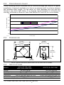
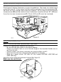
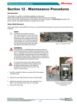
Installation and User Manual VB0026 Furnace Air Exchanger with Heat Recovery CANADIAN MODELS FAE115 vFAE115 FAE115M vFAE115M US MODELS uFAE115 uFAE115M Address of your installer INSTALLER: LEAVE THIS MANUAL TO HOMEOWNER Customer Service Phone Number: 1-800-567-3855 04423 07/04/00 ABOUT THIS MANUAL This manual uses the following symbols to emphasize particular information: ! WARNING Identifies an instruction which, if not followed, might cause serious personal injuries including possibility of death. CAUTION Denotes an instruction which, if not followed, may severely damage the unit and/or its components. NOTE: Indicates supplementary information needed to fully complete an instruction. WARRANTY Venmar Ventilation Inc. or vänEE Canada warrants to the original consumer purchaser of its products, that such products will be guaranteed against all manufacturing defects and defective material for a period of three (3) years and a lifetime warranty on the heat recovery core (used under normal conditions). THERE ARE NO OTHER WARRANTIES, EXPRESS OR IMPLIED, INCLUDING, BUT NOT LIMITED TO, IMPLIED WARRANTIES OF MERCHANTABILITY OR FITNESS FOR A PARTICULAR PURPOSE. VENMAR VENTILATION INC. OR vänEE CANADA WILL NOT BE HELD RESPONSIBLE FOR ANY CLAIMS OVER THE ORIGINAL PURCHASE PRICE OF A FURNACE AIR EXCHANGER WITH HEAT RECOVERY, NOR HELD RESPONSIBLE FOR SUBSEQUENT DAMAGE OR INCIDENT. During the period stated above, Venmar Ventilation Inc. or vänEE Canada will, at its opinion, repair or replace, without charge, any product or part which is found to be defective under normal use and service. This warranty does not cover a) normal maintenance and service, b) any products or parts which have been subject to misuse, negligence, accident, improper maintenance or repairs made by other than Venmar Ventilation Inc or vänEE Canada, or c) a faulty installation or installation contrary to recommended installation instructions. The duration of any implied warranty is limited to the 3-year period as specified for the express warranty. Some states or provinces do not allow limitation on how long an implied warranty lasts, so the above limitation may not apply to you. VENMAR VENTILATION INC. OR vänEE CANADA'S OBLIGATION TO REPAIR OR REPLACE AT VENMAR OR vänEE'S OPTION, SHALL BE THE PURCHASER'S SOLE AND EXCLUSIVE REMEDY UNDER THIS WARRANTY. VENMAR OR vänEE SHALL NOT BE LIABLE FOR INCIDENTAL CONSEQUENTIAL OR SPECIAL DAMAGES ARISING OUT OF OR IN CONNECTION WITH PRODUCT USE OR PERFORMANCE. SOME STATES OR PROVINCES DO NOT ALLOW THE EXCLUSION OR LIMITATION OF INCIDENTAL OR CONSEQUENTIAL DAMAGES, SO THE ABOVE LIMITATION OR EXCLUSION MAY NOT APPLY TO YOU. This warranty gives you specific legal rights and you may also have other rights, which vary from state or province to another. This warranty supersedes all prior warranties. To contact Venmar Ventilation Inc. or vänEE Canada warranty service call 1-800-567-3855 in Canada and United States. In order to qualify for a warranty claim, the owner of a Furnace Air Exchanger with heat recovery must have the model and serial number along with a proof of the original purchase date. At the time of requesting service, describe the nature of any defect in the product or part. In case of discrepancies between the english version of the warranty and the french version, the english version will prevail. 2 TABLE OF CONTENTS 1.0 SERVICE 1.1 1.2 Service Parts . . . . . . . . . . . . . . . . . . . . . . . . . . . . . . . . .4 Parts Ordering Chart . . . . . . . . . . . . . . . . . . . . . . . . . . .4 . . . . . . . . . . . . . . . . . . . . . . . . .4 2.0 TECHNICAL DATA . . . . . . . . . . . . . . . . . . . .4 2.1 2.2 2.3 2.4 Air Distribution . . . . . . . . . . . . . . . . . . . . . . . . . . . . . . . .4 Performance Chart . . . . . . . . . . . . . . . . . . . . . . . . . . . . .5 Dimensions . . . . . . . . . . . . . . . . . . . . . . . . . . . . . . . . . .5 Specifications . . . . . . . . . . . . . . . . . . . . . . . . . . . . . . . . .5 3.0 TYPICAL INSTALLATION . . . . . . . . . . . . . . . .6 4.0 INSTALLATION . . . . . . . . . . . . . . . . . . . . . .6 4.1 4.2 4.3 4.4 Locating and Mounting the Unit . . . . . . . . . . . . . . . . . .6 Connecting Ducts to the Unit . . . . . . . . . . . . . . . . . . . . .7 Installing Exterior Hoods . . . . . . . . . . . . . . . . . . . . . . . .7 Connecting the Drain . . . . . . . . . . . . . . . . . . . . . . . . . . .8 5.0 6.0 AIR FLOW BALANCING . . . . . . . . . . . . . . . . .9 YOUR UNIT . . . . . . . . . . . . . . . . . . . . . .11 6.1 6.2 6.3 Unit Description . . . . . . . . . . . . . . . . . . . . . . . . . . . . . .11 Heat Recovery . . . . . . . . . . . . . . . . . . . . . . . . . . . . . . .11 During Cold Weather . . . . . . . . . . . . . . . . . . . . . . . . . .11 7.0 HOW 7.1 7.2 Instructions Regarding Wall Control . . . . . . . . . . . . . .12 Wiring Diagram . . . . . . . . . . . . . . . . . . . . . . . . . . . . . .12 8.0 MAINTENANCE . . . . . . . . . . . . . . . . . . . . .13 8.1 Every Three Months . . . . . . . . . . . . . . . . . . . . . . . . . . .13 9.0 TROUBLESHOOTING . . . . . . . . . . . . . . . . . .14 TO OPERATE THE UNIT . . . . . . . . . . . . .12 3 1.0 SERVICE 1.1 SERVICE PARTS 3 1 1 2 2 VL0004 FAE115M, uFAE115M & vFAE115M FAE115, uFAE115 & vFAE115 NOTE: Unit in normal position. Can also be installed upside down. 1.2 PARTS ORDERING CHART Number 1. 2. 3. Part Description Basic Filter Heat Recovery Core Damper Motor Part Number 04432 04433 Canada/ 04455 US 04434 2.0 TECHNICAL DATA 2.1 AIR DISTRIBUTION The Figure 1 illustrates the air flow inside units (all models). FRESH AIR FROM OUTSIDE STALE AIR FROM HOUSE STALE AIR TO OUTSIDE FRESH AIR TO HOUSE VF0014 Figure 1 4 2.2 PERFORMANCE CHART These following curves illustrate the air volume through the units for a typical installation. A typical installation is close to an exterior wall, in order to shorten the insulated duct length. On the warm air side (between the unit and the furnace), use steel rigid ducts. It is strongly recommended to minimize the number of elbows to ease air flow. See Section 3.0 and 4.0 for more details. Pressure (in. water gauge) 0.30 0.25 0.20 Stale air Fresh air 0.15 0.10 0.05 0.00 40 50 60 2.3 70 80 90 100 110 120 Flows (cfm) VG0031A DIMENSIONS 27.250” (692 mm) 22.562” (573 mm) 14.500” (368 mm) 20.000” (508 mm) VK0028 2.225” (57 mm) 1.500’’ (38 mm) 6.000” (152 mm) NOTE: Typical illustration; dimensions are the same for all models. 2.4 SPECIFICATIONS FAE115 & FAE115M vFAE115 & vFAE115M Weight 35.3 lbs (16 kg) Port diameter 6 inches (152 mm) Drain diameter 1/2 inch (12 mm) Installation Chains (provided with the unit) Electrical supply* 24 Volts, AC Power consumption* 6 Watts Models * For models FAE115M, uFAE115M and vFAE115M only. 5 uFAE115 & uFAE115M 40.6 lbs (18.4 kg) 6 inches (152 mm) 1/2 inch (12 mm) Chains (provided with the unit) 24 Volts, AC 6 Watts 3.0 TYPICAL INSTALLATION The Figure 2 below illustrates a typical installation. The fresh air intake hood must be at least 6’ (1.8 m) away from the outdoor exhaust hood (measurement A), the fresh air from outside duct must be at least 6’ (1.8 m) away from the furnace (measurement B) and the stale air from inside duct must be at least 18” (457mm) from the furnace (measurement C). Ducts 1, 2 and 3 must be insulated. C 1 A 18" 6' 6' 3 B 2 Figure 2 VH0012 4.0 INSTALLATION 4.1 LOCATING AND MOUNTING THE UNIT Choose an appropriate location for the unit: • So as to provide easy access to the interior cabinet. • Close to an exterior wall, so as to limit the length of the insulated flexible duct to and from the unit. • Close to a drain. (If no drain is close by, use a pail to collect run-off.) • Away from hot chimneys, electrical panel and other fire hazards. • Allow for a power source (120 Volts AC) (For models FAE115M, uFAE115M and vFAE115M only). Hang the unit to ceiling joists with the 4 chains (See Figure 3). Make sure the unit is level. VD0033 Figure 3 6 4.2 CONNECTING DUCTS TO THE UNIT Insulated flexible ducts: Use the following procedure for connecting the insulated flexible ducts to the ports on the unit (exhaust to outside and fresh air from outside). a) Pull back the insulation to expose the flexible duct. b) Connect the interior flexible duct to the opening using a duct tie. c) Carefully seal the connection with duct tape. d) Pull the insulation over the joint and tuck it between the inner and outer rings of double collar. e) Pull the vapor barrier over the insulation and over the outer ring of the double collar. f) Apply duct tape to the joint making an airtight seal. Avoid compressing the insulation when you pull the tape tightly around the joint. A compressed insulation loses its R value and also causes water dripping due to condensation on the exterior surface of the duct. CAUTION Make sure that the vapor barrier on the insulated ducts does not tear during installation. a) VJ0001 4.3 b) c) d), e) VJ0002 VJ0003 VJ0004 f) VJ0005 INSTALLING EXTERIOR HOODS Choose an appropriate location for installing the exterior hoods: • A distance of at least 6 feet (1.8 m) one from the other • A distance of 18 inches (457 mm) from the ground Make sure the intake hood is at least 6 feet (1.8 m) away from any of the following: • dryer exhaust, high efficiency furnace vent, central vacuum vent • gas meter exhaust, gas barbecue-grill • any exhaust from a combustion source • garbage bin and any other source of contamination Refer to Figure 4 for connecting the insulated ducts to the hoods. An “Anti-Gust Intake Hood” should be installed in regions where a lot of snow is expected to fall. 6”Ø (152 mm) Exhaust hood 18” (457mm) Intake hood 18” (457mm) 6’ (1.8m) 6’ (1.8m) VD0034 Figure 4 Optional duct location 7 18” (457mm) 4.4 CONNECTING THE DRAIN a) Attach the 2 plastic drain fittings to the unit using the gaskets and nuts as shown. a) VO0008 b) Cut 2 sections of plastic tubing, about 12”(305 mm) long and attach them to each drain fitting. b) 12" VO0004 c) Join these 2 short sections to the “T” junction and main tube as shown. c) VO0005 d) Make a water trap loop in the tube to prevent the unit from drawing unpleasant odors from the drain source. Make sure this loop is situated BELOW the “T” as shown. This will prevent water from being drawn back up into the unit in case of negative pressure. d) e) e) Run the tubing to the floor drain or to an alternative drain pipe or pail. Be sure there is a slight slope for the run-off. f) Plug the other drain holes not used with two (2) caps and O-rings provided in installation kit. to drain VO0006 8 5.0 AIR FLOW BALANCING What you Need to Balance the Unit • A magnehelic gauge capable of measuring 0 to 0.25 inches water gauge (0 to 62.5 Pa) and 2 plastic tubes. • Two flow collars (6” diameter). VP0005 Flow collar Preliminary Stages for Balancing the Unit Seal all the unit ductwork with tape. Close all windows and doors. Turn off all exhaust devices such as: range hoods, dryers and bathroom fans. Make sure balancing dampers are fully opened (F and G in Figure 5 below). Choose appropriate locations for the 2 flow collars according to Figure 5: • On the exhaust air duct (first measuring location, A) • On the fresh air distribution duct (second measuring location, B) • At least 36”(914 mm) away from the unit; at least 12”(304 mm) before or after a 90° elbow; at least 12”(304 mm) away from a register. 36¨(914mm) A G 12¨(304mm) 12¨(304mm) F B OR VP0008 Figure 5 Installation of Flow Collars Insert the flow collars in the duct at each location. Make sure their arrows are pointing in the direction of the airflow. Tape collars in place temporarily. 9 Balancing procedure 1. Set the furnace blower to high speed. 2.Place the magnehelic gauge on a level surface and adjust it to zero. 3.Connect tubing from gauge to flow collar in exhaust air stream at location A (Figure 5 on page 9). Be sure to connect the tubes to their appropriate high / low fitting. If the gauge reading drops to below zero, reverse the tubing connections. Note: it is better to start with the exhaust air flow reading because the exhaust typically has more restriction than the fresh air. Hold or place the magnehelic gauge upright and level. Record the reading. LOW HIGH FLOW VP0003 4.Move tubing to the other side of the unit (location B in Figure 5 on page 9) and note reading. Adjust the fresh air balancing damper F until the reading at B is approximately the same as the reading at A. If the reading at B is less than the reading at A then go back and adjust the exhaust balancing damper G to equal the fresh air flow. 5.If the furnace has a low speed option, select the low speed option and check if the fresh air flow and the stale air flow are still balanced. LOW HIGH FLOW VP0004 6.Remove flow collars, reconnect the duct and seal with duct tape. Write the required airflow information on a label and stick it near the unit for future reference: (date, maximum speed airflows, your name and phone number and business address). NOTES: • Most flow collar kits provide a conversion chart situated on the collar which enables you to convert magnehelic gauge readings to equivalent cfm values. • A difference of ± 10 cfm ( ± 0.015 inches water gauge) between the 2 readings is considered balanced. • If you are using only one flow collar, then, after completing the first reading, transfer this measuring device to the other side of the unit and take the second reading. 10 6.0 YOUR UNIT 6.1 1. 2. 3. UNIT DESCRIPTION Basic filter Heat recovery core Damper system (only on FAE115M, uFAE115M and vFAE115M units) Unit in normal position. Can also be installed upside down. 3 1 1 2 2 VL0004 FAE115M, uFAE115M & vFAE115M 6.2 FAE115, uFAE115 & vFAE115 HEAT RECOVERY FRESH AIR FROM OUTSIDE 0°C/32°F STALE AIR FROM BUILDING 60°C/140°F (During heating mode) STALE AIR TO OUTSIDE 25°C/77°F INSIDE OUTSIDE This unit is equipped with a heat recovery core, specifically designed to reduce ventilation costs by recovering the heat energy from the exhaust air, and using that same heat energy to warm the fresh air being supplied. This heat recovery process is accomplished in such a way that the stale air is never mixed with the fresh air. Example (in winter): FRESH AIR TO BUILDING 35°C/95°F VF0015 6.3 DURING COLD WEATHER When the outside temperature is below the freezing point, heat recovery creates frost in the module. If the furnace blower is set to operate intermittently, the heat coming from the stale air will prevent unit frosting. CAUTION When the outside temperature is under -10°C (14°F), the furnace must operate intermittently in heating mode to prevent frost accumulation inside the unit. 11 7.0 HOW TO OPERATE THE UNIT If you owns a FAE115,a uFAE115 or a vFAE115 model, this Section doesn’t concern your unit. Please refer to the next Sections. 7.1 INSTRUCTIONS REGARDING WALL CONTROL (FAE115M, UFAE115M AND VFAE115M ONLY) This wall control works with a dehumidistat that allows you to select the desired humidity level according to your needs. If the selector is set above the click, the unit will close its damper and stop air exchange with outside. If the selector is set below the click, the unit will open its dampers and allow air exchange with the outside until the desired humidity level has been reached. Venmar part number: #11297, vänEE part number: #200694. CAUTION Some activities create dust or vapors wich may damage your unit. You must turn off your unit and unplug it in the following situation: • Major renovation work • House building • Sanding of gypsum joints • Varnishing During very heavy snow storm, the unit should also be turned off to avoid problems caused by snow entering the unit, if it is not equipped with an anti-gust intake hood. 7.2 WIRING DIAGRAM BLUE Connect transformer wires to unit terminals 1 and 3 and connect wall control wires to unit terminals 1 and 2, as shown below. E U BL BLACK BLACK 1 2 3 Damper Actuator 24 Vac Class 2 Wall Control Class 2 Transformer Not supplied Field wiring not supplied VE0014A 12 120 Vac 8.0 MAINTENANCE ! WARNING We take great care to keep sharp edges to a minimum, but please be careful when handling components. NOTE: Unit shown is in reverse position but the unit can be installed in either the “normal” or “reverse” (upside down) position. MAINTENANCE 8.1 PROCEDURE: EVERY THREE MONTHS Regular maintenance should be performed every 3 months. 1. Set the wall control to 80%. (FAE115M, uFAE115M and vFAE115M only) 2. Unlatch the door. Lift the panel towards you. Hold it firmly and hit on the right side of the pannel. The door should slide to the left. VO0007 3. Clean the filter • Remove filter. • Vacuum to remove most of the dust. • Wash with a mixture of warm water and mild soap. You may add bleach if you wish to disinfect (one tablespoon per gallon or per 4 liters). Rinse thoroughly. Shake filter to remove excess water and let dry. NOTE: Washing the filter in the top tray of the dishwasher is possible, but the aluminum frame might tarnish. CAUTION Handle the heat recovery core with care. 4. 5. Remove and clean the heat recovery core. • Let it soak in a mixture of cold or lukewarm water and mild soap (dishwashing liquid). • Rinse thoroughly. • Shake the core to remove excess water and let it dry. VO0009 Clean the condensation tray with a damp cloth. VD0035 13 8.1 EVERY THREE MONTHS (cont’d) 6. Reinstall the components: • Heat recovery core • Filter • Door (The door is secured when you hear a click.) 7. Check the exterior air intake hood : • Make sure there are no leaves, twigs, ice or snow that could be drawn into the vent. • Clean if necessary. CAUTION Even a partial blocking of this air vent could cause the unit to malfunction. 8. Set the wall control to its previous position (FAE115M, uFAE115M and vFAE115M only). 9.0 Troubleshooting If you think your unit is malfunctioning, check some of the following. TYPE OF PROBLEM TRY THIS... 1 Nothing works. (models FAE115M, uFAE115M and vFAE115M only) • See if the transformer is plugged in. • See if the transformer is receiving power from the house circuit breaker. 2 Condensation on windows. (Air too humid.) • Adjust the humidity control knob as per instructions (see Section 7) (FAE115M, uFAE115M and vFAE115M models only). • Leave curtains half-open to allow air circulation. • Store all firewood in a close room with a dehumidifier or in a well ventilated room, or store the wood outside. • Keep the temperature in your house above 18°C (64°F). 3 Air too dry. • Adjust your humidity control over the click (FAE115M, uFAE115M and vFAE115M models only). • Temporarily use a humidifier. 14