1
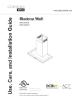
Use, Care, and Installation Guide
www.zephyronline.com
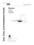
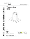
Milano Island
ZML-M90BG
ZML-M90BS
ZML-E42BG
ZML-E42BS
Model number:
Serial Number:
APR14.0701 © Zephyr Corporation
For use with models of serial numbers beginning with 21
+
C
TM
Airflow Control Technology
www.zephyronline.com
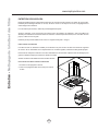
INSTALLATION
Ducting Calculation Sheet .......................................
Mounting Height & Clearance................................
Ducting Options ...........................................................
+RRG6SHFL¿FDWLRQV ...................................................
Mounting the Hood .....................................................
Ductless Recirculating ..............................................
5
6
7
8
9-12
13
FEATURES & CONTROLS
Touch Controls ............................................................. 14
User Interface ............................................................... 15
MAINTENANCE
Hood and Filter Cleaning ......................................... 16
TROUBLESHOOTING................................................................ 17
FAN CURVE DIAGRAMS ......................................................... 18-19
WIRING DIAGRAM ...................................................................... 20
LIST OF PARTS AND ACCESSORIES .............................. 21
1
Table of Contents
SAFETY NOTICE ................................................................. 2-3
LIST OF MATERIALS....................................................... 4
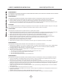
Important Safety Notice
READ AND SAVE THESE INSTRUCTIONS
www.zephyronline.com
WARNING
TO REDUCE THE RISK OF FIRE OR ELECTRIC SHOCK, DO NOT USE THIS FAN WITH ANY SOLID-STATE CONTROL DEVICE.
WARNING
TO REDUCE THE RISK OF FIRE ELECTRIC SHOCK, OR INJURY TO PERSONS, OBSERVE THE FOLLOWING:
a. Use this unit only in the manner intended by the manufacturer, if you have questions, contact the manufacturer.
b. Before servicing or cleaning unit, switch power off at service panel and lock panel to prevent power from being switched on accidentally.
When the service disconnecting means cannot be locked, securely fasten a prominent warning device, such as a tag, to the service
panel.
CAUTION
For general ventilating use only. Do not use to exhaust hazardous or explosive materials and vapors. Take care when using cleaning
agents or detergents. Suitable for use in household cooking area.
WARNING
TO REDUCE THE RISK OF RANGE TOP GREASE FIRE:
a. Never leave surface units unattended at high settings. Boilovers cause smoking and greasy spillovers that may ignite. Heat oils slowly
on low or medium settings.
E $OZD\VWXUQKRRG21ZKHQFRRNLQJDWKLJKKHDWRUZKHQÀDPLQJIRRG
F &OHDQYHQWLODWLQJIDQVIUHTXHQWO\*UHDVHVKRXOGQRWEHDOORZHGWRDFFXPXODWHRQIDQRU¿OWHU
d. Use proper pan size. Always use cookware appropriate for the size of the surface element.
H .HHSIDQ¿OWHUVDQGJUHDVHODGHQVXUIDFHVFOHDQ
f. Use high setting on hood only when necessary.
g. Don’t leave hood unattended when cooking.
h. Always use cookware and utensils appropriate for the type of and amount of food being prepared.
WARNING
TO REDUCE THE RISK OF INJURY TO PERSONS IN THE EVENT OF A RANGE TOP FIRE, OBSERVE THE FOLLOWING:
D 6027+(5)/$0(6ZLWKDFORVH¿WWLQJOLGFRRNLHVKHHWRUPHWDOWUD\WKHQWXUQRIIWKHEXUQHU%(&$5()8/7235(9(17%8516
,IWKHÀDPHVGRQRWJRRXWLPPHGLDWHO\(9$&8$7($1'&$//7+(),5('(3$570(17
b. NEVER PICK UP A FLAMING PAN – You may be burned.
c. DO NOT USE WATER, including wet dishcloths or towels – a violent steam explosion will result.
d. Use an extinguisher ONLY if:
1. You know you have a Class ABC extinguisher, and you already know how to operate it.
7KH¿UHLVVPDOODQGFRQWDLQHGLQWKHDUHDZKHUHLWVWDUWHG
7KH¿UHGHSDUWPHQWLVEHLQJFDOOHG
<RXFDQ¿JKWWKH¿UHZLWK\RXUEDFNWRDQH[LW
WARNING
TO REDUCE THE RISK OF FIRE, ELECTRIC SHOCK OR INJURY TO PERSONS, OBSERVE THE FOLLOWING:
D ,QVWDOODWLRQZRUNDQGHOHFWULFDOZLULQJPXVWEHGRQHE\TXDOL¿HGSHUVRQVLQDFFRUGDQFHZLWKDOODSSOLFDEOHFRGHVDQGVWDQGDUGV
,QFOXGLQJ¿UHUDWHGFRQVWUXFWLRQ
E 6XI¿FLHQWDLULVQHHGHGIRUSRZHUFRPEXVWLRQDQGH[KDXVWLQJRIJDVHVWKURXJKWKHÀXHFKLPQH\RIIXHOEXUQLQJHTXLSPHQWWRSUHYHQW
back-drafting. Follow the heating equipment manufacturer’s guideline and safety standards such as those published by the National
)LUH3URWHFWLRQ$VVRFLDWLRQ1)3$DQGWKH$PHULFDQ6RFLHW\IRU+HDWLQJ5HIULJHUDWLRQDQG$LU&RQGLWLRQLQJ(QJLQHHUV$6+5$(DQG
the local code authorities.
c. When cutting or drilling into wall or ceiling, do not damage electrical wiring and other hidden utilities.
d. Ducted fans must always vent to the outdoors.
e. If this unit is to be installed over a tub or shower, it must be marked as appropriate for the application and be connected to a GFI
*URXQG)DXOW,QWHUUXSWHUSURWHFWHGEUDQFKFLUFXLW
g. NEVER place a switch where it can be reached from a tub or shower.
h. Make sure the power is off before installing, wiring or maintenancing.
2
TO REDUCE THE RISK OF FIRE, USE ONLY METAL DUCTWORK.
NOT FOR USE IN OUTDOOR COOKING ENVIRONMENTS.
CAUTION
7RUHGXFHULVNRI¿UHDQGWRSURSHUO\H[KDXVWDLURXWVLGH'RQRWYHQWH[KDXVWDLULQWRVSDFHVZLWKLQZDOOVFHLOLQJV
attics, crawl spaces or garages.
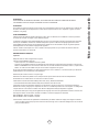
OPERATION
$OZD\VOHDYHVDIHW\JULOOHVDQG¿OWHUVLQSODFH:LWKRXWWKHVHFRPSRQHQWVRSHUDWLQJEORZHUVFRXOGFDWFKRQWRKDLU¿QJHUV
and loose clothing.
The manufacturer declines all responsibility in the event of failure to observe the instructions given here for installation,
maintenance and suitable use of the product. The manufacturer further declines all responsibility for injury due to
negligence and the warranty of the unit automatically expires due to improper maintenance.
*NOTE: Please check www.zephyronline.com for revisions before doing any custom work.
ELECTRICAL REQUIREMENTS
Important:
Observe all governing codes and ordinances.
It is the customer’s responsibility:
7RFRQWDFWDTXDOL¿HGHOHFWULFDOLQVWDOOHU
- To assure that the electrical installation is adequate and in conformance with National Electrical Code, ANSI/NFPA 70
latest edition* or CSA standards C22.1-94, Canadian Electrical Code, Part 1 and C22.2 No.0-M91 - latest edition** and
all local codes and ordinances.
,IFRGHVSHUPLWDQGDVHSDUDWHJURXQGZLUHLVXVHGLWLVUHFRPPHQGHGWKDWDTXDOL¿HGHOHFWULFLDQGHWHUPLQHWKDWWKH
ground path is adequate.
Do not ground to a gas pipe.
&KHFNZLWKDTXDOL¿HGHOHFWULFLDQLI\RXDUHQRWVXUHWKHUDQJHKRRGLVSURSHUO\JURXQGHG
Do not have a fuse in the neutral or ground circuit.
*National Fire Protection Association Batterymarch Park, Quincy, Massachusetts 02269
** CSA International 8501 East Pleasant Valley Road, Cleveland, Ohio 44131-5575
This appliance requires a 120V 60Hz electrical supply and connected to an individual properly grounded branch circuit
protected by a 15 or 20 ampere circuit breaker or time delay fuse. Wiring must be 2 wire with ground. Please also refer to
Electrical Diagram on product.
$FDEOHORFNLQJFRQQHFWRUQRWVXSSOLHGPLJKWDOVREHUHTXLUHGE\ORFDOFRGHV&KHFNZLWKORFDOUHTXLUHPHQWVSXUFKDVH
and install appropriate connector if necessary.
ZML-M90BG/BS - MAX 215 Watts, 4 Amps
ZML-E42BG/BS - MAX 215 Watts, 4 Amps
3RZHUFRQVXPSWLRQVKRZQDERYHLVWKHGHIDXOWSRZHUVSHFV+RRGVZLWK=HSK\U¶VSURSULHWDU\$LUÀRZ&RQWURO7HFKQRORJ\
$&7HQDEOHGZLOOFRQVXPHOHVVSRZHU6HHZLULQJGLDJUDPDWWKHHQGRIWKLVPDQXDOIRUPRUHLQIRUPDWLRQ
3
Important Safety Notice
WARNING
www.zephyronline.com
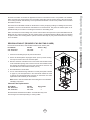
MODELS: ZML-M90BG/BS , ZML-E42BG/BS
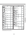
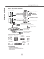
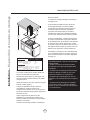
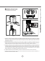
PARTS SUPPLIED
1 - Top support frame
Front of Hood
C/ L
B
Cut-Out Shaded Area
1 - Paper ceiling
2 - Top duct covers
2 - Thick trim pieces
template
A
1 - Square support frame bracket
2 - Bottom duct covers
2 - Thin trim pieces
1 - Bottom support frame
1 - 8” round damper (pre-installed)
1 - Hood body w/ blower (pre-installed)
2 - Lateral support brackets
1 - Canopy, glass or stainless
4 - 3W LED lights
2 - Aluminum mesh filters
1 - Hardware package
HARDWARE PACKAGE CONTENTS
(3) Wire Nuts
(4) M6 x 1-1/2”
wood screws
(6) 3/16 x 1/4 pan-head
machine screws
(14) M3 x 5 pan-head
duct cover screws
(20) M4 x 8 pan-head
machine screws
PARTS NOT SUPPLIED
- Ducting, conduit and all installation tools
- Cable connector (if required by local codes)
- Duct cover extension accessory
- Recirculating kit accessory
4
(4)ø12 OD / ø5
ID Washers
(2) M4 x 8 truss-head (1) M4 x 12
sheet-metal screws
safety screw
Equivalent number
length x used
=
Duct pieces
Total
Total
3-1/ 4” x 10” 1 Ft.
Rect.,
straight
x(
) =
Ft.
6”- 8” Round 30 Ft.
wall cap
with damper
x(
) =
Ft.
7” Round,
straight
1 Ft.
x(
) =
Ft.
6”- 8” Round, 30 Ft.
roof cap
x(
) =
Ft.
8” Round,
straight
1 Ft.
x(
) =
Ft.
6” round to
1 Ft.
3-1/ 4” x 10”
rect.
transition
x(
) =
Ft.
3-1/ 4” x 10” 15 Ft.
Rect. 90 0
elbow
x(
) =
Ft.
x(
) =
Ft.
3-1/ 4” x 10” 9 Ft.
Rect. 45 0
elbow
x(
) =
Ft.
6” round to
16 Ft.
3-1/ 4” x 10”
rect.
transition
90 0 elbow
7” or 8”
Round,
90 0 elbow
15 Ft.
x(
) =
Ft.
3-1/ 4” x 10” 24 Ft.
Rect. 90 0
flat elbow
x(
7” or 8”
Round,
45 0 elbow
9 Ft.
x(
) =
Ft.
3-1/ 4” x 10” 30 Ft.
Rect.
wall cap
with damper
x(
7” or 8”
30 Ft.
Round
wall cap
with damper
x(
) =
Ft.
3-1/ 4” x 10” 5 Ft.
Rect. to
6” round
transition
x(
) =
Ft.
7” or 8”
Round,
roof cap
x(
) =
Ft.
3-1/ 4” x 10” 20 Ft.
Rect. to
6” round
transition
90 0 elbow
x(
) =
Ft.
7” round to
8 Ft.
3 1/ 4” x 10”
rect.
transition
x(
) =
Ft.
) =
Ft.
15 Ft.
x(
) =
Ft.
7” round to
23 Ft.
3-1/ 4” x 10”
rect.
transition
90 0 elbow
x(
8” Round,
90 0 elbow
8” Round,
45 0 elbow
9 Ft.
x(
) =
Ft.
Subtotal column 2 =
Ft.
Subtotal column 1 =
Ft.
Total ductwork
Ft.
) =
) =
Subtotal column 1 =
Ft.
Ft.
Ft.
Maximum Duct Length: For satisfactory air movement,
the total duct length of duct should not exceed 100 equivalent feet.
5
30 Ft.
=
Installation – Ducting Calculation Sheet
Equivalent number
length x used
=
Duct pieces
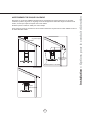
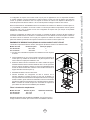
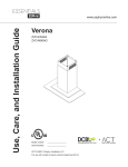
Installation – Mounting Height & Clearance
www.zephyronline.com
ALWAYS, when possible, reduce the number of
transitions and turns. If a long duct run is required,
increase duct size from 8” to 10”.
If turns or transitions are required: Install as far
away from duct opening and as far apart between
the two transitions as possible.
A
n.
mi . B
n
i
m .C
x
ma
D
n.
mi . E
n
i
m .F
x
ma
Minimum mount height between range top to hood
bottom should be no less than 26”.
Maximum mount height should be no higher than
34”.
in.
” max.
6
2 ”m
34
It is important to install the hood at the proper
mounting height. Hoods mounted too low could
UHVXOWLQKHDWGDPDJHDQG¿UHKD]DUGZKLOHKRRGV
mounted too high will be hard to reach and will
ORRVHLWVSHUIRUPDQFHDQGHI¿FLHQF\
If available, also refer to range manufacturer’s
height clearance requirements and recommended
hood mounting height above range. Always check
your local codes for any differences.
”
36
Standard
Hood Heights
Duct Cover
minimum ducted (A) 28 1/2”
minimum recirculating (B) 32 1/2”
maximum (C) 50”
Ceiling Heights
minimum ducted (D)
minimum recirculating (E)
maximum (F)
Duct cover extension kit available for ceiling heights
up to 12 feet. Turn to page 21 for part number and
ordering information.
Extension
Duct Cover
44“
48 1/2“
82”
90 1/2” (7’ 6 1/2”) 106“ (8‘ 10”)
94 1/2” (7’10 1/2”) 110 1/2“ (9’2 1/2”)
120” (10’)
152” (12’ 8”)
DUCTING
A minimum of 8” round duct is recommended to
PDLQWDLQPD[LPXPDLUÀRZHI¿FLHQF\
Always use rigid type metal ducts only. Flexible
GXFWVFRXOGUHVWULFWDLUÀRZE\XSWR
Use calculation worksheet to compute total duct
ZRUN3DJH
6
DAMAGE-SHIPMENT / INSTALLATION:
3OHDVHIXOO\LQVSHFWXQLWIRUGDPDJHEHIRUH
installation.
,IWKHXQLWLVGDPDJHGLQVKLSPHQWUHWXUQWKH
unit to the store in which it was bought for
repair or replacement.
,IWKHXQLWLVGDPDJHGE\WKHFXVWRPHUUHSDLU
or replacement is the responsibility of the
customer.
,IWKHXQLWLVGDPDJHGE\WKHLQVWDOOHULIRWKHU
WKDQWKHFXVWRPHUUHSDLURIUHSODFHPHQWPXVW
be made by arrangement between customer
and installer.
NEVER exhaust air or terminate duct work into spaces between walls, crawl spaces, ceiling, attics or garages.
All exhaust must be ducted to the outside, unless using the recirculating option.
Use single wall rigid Metal ductwork only.
)DVWHQDOOFRQQHFWLRQVZLWKVKHHWPHWDOVFUHZVDQGWDSHDOOMRLQWVZFHUWL¿HG6LOYHU7DSHRU'XFW7DSH
Some Ducting Options
Roof Pitch w/
Flashing & Cap
(blower
housing)
(blower
housing)
Soffit or crawl space
(blower
housing)
ductless
recirculating
7
side wall cap
w/ gravity damper
Installation – Ducting Options
WARNING FIRE HAZARD
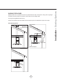
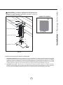
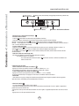
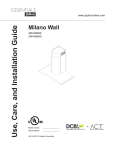
12 15/16”
12 3/4”
9 11/16”
6 11/16”
STANDARD
min. ducted - 28 1/2”
min. recirc. - 32 1/2”
max. - 50”
14 1/8”
Z1C-03ML
min. ducted - 44”
min. recirc. - 48 1/2”
max. - 82”
23 15/16”
25 9/16”
35 5/16”, 42”
FRONT
SIDE
10 9/16”
9 11/16”
1 1/4”
C/L
C/L
4”
AC In
71
10 15/16”
C/L
5/1
6”
2 3/16”
5 5/16”
4 13/16”
5/8”
Installation –+RRG6SHFL¿FDWLRQV
www.zephyronline.com
TOP SUPPORT FRAME
TOP of HOOD
(top view)
8
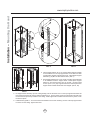
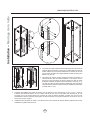
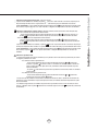
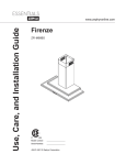
PAPER TEMPLATE
Front of Hood
B
Cut-Out Shaded Area
Ceiling Joists
Wood Blocking
1
fron
t
3
Top Support Frame
A
2
FIG. B
Bottom Support Frame
6
5
Hood Body/Canopy
4
FIG. A
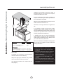
+RRGLVLQWHQGHGWREHPRXQWHGWRD¿QLVKHGFHLOLQJ
1. Ceiling Preparation:'HWHUPLQHKRRGPRXQWLQJORFDWLRQDQGWHPSRUDULO\WDSHSDSHUWHPSODWHLQFOXLGHGZLWKWKH
KRRGWRWKHFHLOLQJ&XWRXWLQWHUQDOVKDGHGDUHDRIWHPSODWHWRDOORZWKHGXFWQJDQGHOHFWULFDOWRSDVVWKURXJK
$GGZRRGEORFNLQJPLQ´[´RQWRFHLOLQJMRLVWVWRUH¿QIRUFHFHLOLQJDERYHWKHGU\ZDOO),*$6HFXUH
1-1/2´ZRRGVFUHZVLQWRSRLQWV$DQG%RIWKHSDSHUWHPSODWH),*%'RQRWFRPSOHWHO\WLJKWHQVFUHZVOHDYH
approx. 1/4” exposed.
2. Hood Preparation: Remove screws securing top and bottom support frames together. Adjust support frame to
DFFRPRGDWHWKHGHVLUHGKRRGKHLJKWDQGUHDVVHPEOHWKHIUDPHXVLQJWKHSUHYLRXVO\UHPRYHGVFUHZVVFUHZV
IRUHDFKVXSSRUWIUDPHDUP),*$
9
Installation – Mounting the Hood
! WARNING: Electrical wiring must be done by a qualified person(s) in
accordance with all applicable codes and standards. This range hood must be
properly grounded. Turn off electrical power at service entrance before wiring.
Installation – Mounting the Hood
www.zephyronline.com
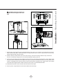
FIG. C
FIG. D
FRONT
FRONT
3. Hood heights between 40” to 50” require lateral support brackets
to be installed to the two top support frame cut off arms and their
corresponding bottom support frame arms. Install lateral support
EUDFNHWVE\0[VKHHWPHWDOVFUHZV),*&
1
2
4. Hood heights between 45” to 50” require a square support bracket
to be installed inside the support frame. Install square support
EUDFNHW WR WRS VXSSRUW IUDPH DUPV E\ 0 [ VKHHW PHWDO
VFUHZV ),* ( 7RS VXSSRUW IUDPH DUPV H[WHQG SDVW ORZHU
VXSSRUWIUDPHEUDFNHWZLWKVKRUWHUKRRGKHLJKWV),*(
FIG. E
5. Lift support frame assembly up to the ceiling making sure the the word “front” on the top support frame faces the
IURQWRIWKHKRRGZKHUHWKHFRQWUROVZLOOEHORFDWHG),*'7KHNH\KROHVRQWKHWRSVXSSRUWIUDPHVKRXOGFRYHU
the wood screws previously installed in the ceiling. Slide support frame towards narrow end of key-holes to lock
the frame in place.
,QVWDOOWKHODVW0[´ZRRGVFUHZVZLWKZDVKHUVLQWRWKHWZRUHPDLQLQJFRUQHUVRIWKHWRSVXSSRUWIUDPH
to secure it to the ceiling. Tighten all screws.
10
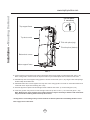
BLOWER
HOUSING
ELECTRONICS
MOUNTING
BRACKET
FIG. G
1
1
2
FIG. H
FIG. F
5HPRYHWDSHVHFXULQJHOHFWURQLFVPRXQWLQJEUDFNHWWRKRRG),*)5HPRYHVFUHZVIURPWRSRIKRRG
ERG\DQGVHWVFUHZVDVLGH3RVLWLRQHOHFWURQLFVPRXQWLQJEUDFNHWDVVKRZLQ),*)DQGVHFXUHWRKRRGERG\
XVLQJWKHSUHYLRXVO\UHPRYHGVFUHZV
8. Remove aluminum mesh filters from hood. Place canopy over blower housing located on top of hood and
VHFXUHLWWRKRRGERG\XVLQJ[VFUHZVWKURXJK¿OWHURSHQLQJ),**
/LIWKRRGERG\DQGDOLJQWKHSUHLQVWDOOHGPRXQWLQJVFUHZVRQWRSRIEORZHUKRXVLQJ),*$RQ3DJHZLWK
WKHNH\KROHVRQWKHERWWRPRIWKHVXSSRUWIUDPH),*+6OLGHKRRGWRZDUGVWKHQDUURZHQGRINH\KROHVWRORFN
LQSODFH+DQGWLJKWHQHDFKRIWKHVFUHZVWRVHFXUHKRRGWRERWWRPRIVXSSRUWIUDPH,QVWDOO0[PPVDIHW\
VFUHZLQWRERWWRPVXSSRUWIUDPHWRIXUWKHUVHFXUHWKHKRRG),*+5HLQVWDOOPHVK¿OWHUV
10. Install electrical and duct work. Seal duct work with aluminum duct tape.
11. Power up hood, verify all functions and check for leaks around duct tape.
11
Installation – Mounting the Hood
! CAUTION: At least two installers are
required due to the weight and size of the
hood.
Installation – Mounting the Hood
www.zephyronline.com
cut trim piece
if necessary
1
Top support frame
Top duct covers
2
5 Thick trim piece (top)
4 Thin trim piece (bottom)
Bottom duct covers
3
Bottom support frame
FIG. J
6HFXUHWRSGXFWFRYHUVZLWKORXYHUKROHVWRWRSVXSSRUWIUDPHXVLQJ0[WUXVVKHDGVFUHZV),*-
Note: If using hood in “ducted mode” the top duct covers may be turned upside-down to hide the louver holes.
$VVHPEOHWRSGXFWFRYHUVWRJHWKHUXVLQJ0[VFUHZVRQHDFKVLGH),*-/DUJHUVFUHZKROHRSHQLQJV
should overlap the smaller holes.
$VVHPEOHERWWRPGXFWFRYHUVWRJHWKHURYHUWRSGXFWFRYHUVXVLQJ0[VFUHZVRQHDFKVLGH%RWWRPGXFW
FRYHUVZLOOUHVWRQWRSRIWKHKRRGERG\),*-
,QVHUWWKHWKLQWULPSLHFHVLQWROHIWDQGULJKWVHDPVRIERWWRPGXFWFRYHUVRQHDFKVLGH),*-
,QVHUWWKHWKLFNWULPSLHFHVLQWROHIWDQGULJKWVHDPVRIWRSGXFWFRYHUVRQHDFKVLGH),*-
Note: Because less of the top duct covers will be exposed, it may be necessary to measure and cut the thick
trim pieces before installing them into the top duct covers.
* If using hood in recirculating mode you must install the air diverter plate before assembling the duct covers.
Turn to page 13 for instructions.
12
We recommend to ALWAYS exhaust air outside of the home by employing existing or installing new duct work,
LISRVVLEOH7KHKRRGLVPRVWHIIHFWLYHDQGHI¿FLHQWDVDQH[KDXVWKRRG2QO\ZKHQWKHH[KDXVWRSWLRQLVQRW
possible should you recourse to converting the hood into a recirculating hood.
:KHQFRQYHUWHGWREHDUHFLUFXODWLQJKRRGDVHWRIFKDUFRDO¿OWHUVDUHUHTXLUHGRQWRSRILWVVWDQGDUG$OXPLQXP
Mesh Filter set. Order according to its Part number below. The standard Aluminum Mesh Filters are intended
WRFDSWXUHUHVLGXHIURPFRRNLQJDQGWKHRSWLRQDOFKDUFRDO¿OWHUVKHOSWRSXULI\IXPHVH[KDXVWHGIURPFRRNLQJ
for re-circulation.
RECIRCULATING KIT (REQUIRED IF NO DUCTING IS USED)
.LWLQFOXGHVFKDUFRDO¿OWHUVFKDUFRDO¿OWHUEUDFNHWDQGDLUGLYHUWHUSODWH
Hood Model
ZML-M90BG/BS
ZML-E42BG/BS
Part No.
ZRC-00ML
ZRC-00ML
Filters in Pkg.
2
2
1. Purchase recirculating kit per the part number above
6HFXUHDLUGLYHUWHUSODWHWRWRSVXSSRUWIUDPH),*.5XQ´GXFWLQJ
from top of hood and secure to air diverter plate.
5HPRYHDOXPLQXPPHVK¿OWHUVIURPKRRG,QVWDOOFKDUFRDO¿OWHUEUDFNHW
WRWKHLQVLGH¿OWHURSHQLQJ1RWHVFUHZVWRVHFXUHFKDUFRDO¿OWHUEUDFNHW
DUH DOUHDG\ SUHLQVWDOOHG LQ WKH KRRG DQG PXVW ¿UVW EH UHPRYHG &OLS
FKDUFRDO¿OWHUVLQWRFKDUFRDO¿OWHUEUDFNHW),*.
5HLQVWDOODOXPLQXPPHVK¿OWHUV
7XUQRQFKDUFRDO¿OWHUFKDQJHLQGLFDWRURQFRQWUROSDQHOUHIHUWRGHWDLOV
RQSDJH7KHPLFURSURFHVVRULQWKHFRQWUROVZLOOLQGLFDWHWKHQHHG
WRFKDQJHWKHFKDUFRDO ¿OWHUDIWHUKRXUVRIFRQWLQXRXV XVH2UGHU
UHSODFHPHQWFKDUFRDO¿OWHUVSHUWKHOLVWEHORZ
Note: Refer to manual included with recirculating kit for more detailed
installation instructions.
Charcoal Filter Replacements
Hood Model
ZML-M90BG/BS
ZML-E42BG/BS
Part No.
Z0F-C002
Z0F-C002
Qty to Order
2
2
FIG. K
'2127:$6+&+$5&2$/),/7(56&KDUFRDO¿OWHUVPD\QHHG
to be changed more often depending on cooking habits.
13
Installation – Ductless Recirculating
Ductless recirculation is intended for applications where an exhaust duct work is not possible to be installed.
When converted, the hood functions as a recirculating hood rather than an exhaust hood. Fumes and exhaust
IURPFRRNLQJDUHGUDZQDQG¿OWHUHGE\DVHWRIRSWLRQDOFKDUFRDO¿OWHUV7KHDLULVWKHQSXUL¿HGDQGUHFLUFXODWHG
back within the home.
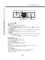
Features & Controls - Touch Controls
www.zephyronline.com
Power / Delay Off
Display (speed level, delay off, filter clean/change,clean air)
clean mesh filter
clean air
replace charcoal filter
Adjust 6 Speed Levels
Lights On/Dim/Off
1 Power / Delay Off Button
Power Button Function
- Button will turn power on and off for entire hood (fan and lights).
- Hood will remember the last speed and light level it was turned off at.
(Example: Press Button to turn off hood when on fan speed 4 and high lights. Press Button again and the hood
will turn back on at speed 4 and high lights level.)
Delay Off Button Function
- Press and hold Button for two seconds and the fan will turn on speed 1. The Graphic will illuminate. After five minutes
the fan and lights will automatically turn off.
- Pressing Button while Delay Off Function is enabled will turn the hood off and cancel the Delay Off Function.
ACT Verification
- Airflow Control Technology (ACT) allows the installer to set the maximum blower CFM to align with local codes and regulations.
- To verify the maximum blower CFM:
- With hood off, hold the Button for three seconds. The blower CFM will be displayed on the LCD.
2 Speed Selection Button
Fan Speed Decrease Button
- Press this button to decrease fan speed. 6 (burst), 5, 4, 3, 2, 1.
- If fan is On Speed 1 and this button is pressed, fan will power Off.
Fan Speed Increase Button
- Press this button to increase fan speed. Fan On, 1, 2, 3, 4, 5, 6 (burst).
- If hood is Off and this button is pressed, fan will turn On Speed 1.
Burst Mode
- This speed level is intended to be used as a quick burst of air extraction when excess cooking fumes and smoke are
generated. After 3 minutes the fan will automatically change to Speed 5.
3 Lights Button
- Lights are two levels, High and Low.
- From off, press one time for High. LCD will show the words “lights hi” for 2 seconds then fade away.
- Press again for Low. LCD will display the words “lights lo” for 2 seconds then fade away.
- Press again to power lights off.
14
Charcoal Filter Replace Indicator (disabled by default, must be enabled if recirculating hood)
- To enable Charcoal Filter Replacement Function:
- With hood off, hold
Button and
Button simultaneously for three seconds. The
Graphic will illuminate for
three seconds indicating the Charcoal Filter Replacement Function is enabled.
- To disable Charcoal Filter Replacement Function:
- With hood off, hold
Button and
Button simultaneously for three seconds. The
Graphic will be
illuminated then turn off indicating the Charcoal Filter Replacement Function is disabled.
- After 120 hours of fan usage the
Graphic and words “replace charcoal filter” will illuminate indicating it is time to
replace the charcoal filter. Graphic and words will remain illuminated until reset.
- To reset: With hood off, hold the
Button for three seconds, after three seconds the
Graphic and words “replace
charcoal filter” will turn off and the 120 hour timer will reset.
Clean Air Indicator
- Clean Air is a feature that turns the fan on every 4 hours for 10 minutes to remove stagnant air in the kitchen.
- To enable Clean Air Function:
- With hood off, hold the Button and
Button simultaneously for three seconds. The
Graphic and
words “clean air” will illuminate and the fan will turn on speed 1 for 10 minutes. After 10 minutes the fan
will turn off and the 4 hour timer will begin.
Graphic will remain on when Clean Air Function is enabled, even if fan is not on.
- To disable Clean Air Function:
- With hood off, hold the
Button and
Button simultaneously for three seconds until
Graphic
turns off.
- When the Clean Air Function is enabled the fan will turn on speed 1 for 10 minutes every 4 hours of non fan usage. After 10
minutes the fan will turn off and the 4 hour timer will reset.
- If the user changes the fan speed while the Clean Air Function is in use, the words “clean air” will turn off but the Graphic
will remain illuminated. If the user presses the Button at any time the 4 hour clean air timer will reset.
15
Features & Controls – User Interface
Mesh Filter Clean Indicator (always enabled)
- After 30 hours of fan usage the Graphic and words “clean mesh filter” will illuminate indicating it is time to clean
the mesh filters. Graphic and words will remain illuminated until reset.
- To reset: With hood off, hold the Button for three seconds, after three seconds the
Graphic and words “clean mesh
filter” will turn off and the 30 hour timer will reset.
Maintenance – Hood and Filter Cleaning
www.zephyronline.com
SURFACE MAINTENANCE:
Clean the hood surface periodically with hot soapy water and clean cotton cloth. Do not use corrosive or
abrasive detergent, or steel wool/scouring pads which will scratch and damage surface.
For heavier soil use liquid degreaser.
After cleaning it is recommended that you use non-abrasive stainless steel polish/cleaners, to polish and buff
out the stainless luster and grain. Always scrub lightly, with clean cotton cloth, and with the grain.
Do not use any product containing chlorine bleach. Do not use “orange” cleaners.
Aluminum Mesh Filters
7KHDOXPLQXPPHVK¿OWHUVLQVWDOOHGE\WKHIDFWRU\DUHLQWHQGHGWR¿OWHURXWUHVLGXHDQGJUHDVHIURPFRRNLQJ
They need not be replaced on a regular basis but are required to be kept clean.
Remove and clean by hand or in dishwasher on low heat. Spray degreasing detergent and leave to soak if
heavily soiled.
'U\¿OWHUVDQGUHLQVWDOOEHIRUHXVLQJKRRG
Removing Aluminum Mesh Filters
1. Push in on spring loaded handle
3XOOGRZQRQ¿OWHUKDQGHWRUHPRYH¿OWHU
16
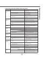
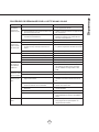
Issue
Cause
What to do
After installation,
the unit doesn’t
work.
1. The power source is not turned ON.
1. Make sure the circuit breaker and the unit’s
power is ON.
2. The power line and the cable locking connector
is not connecting properly.
2. Check the power connection with the unit is
connected properly.
3. The wires on the control board are loose.
3. Make sure the wires on the control board are
connected properly.
4. The switch board and control board wirings are
disconnected.
4. Make sure the wirings between the switch
board and control board are connected
properly.
5. The switch board or control board is defective.
5. Change the switch board or control board.
1. The blower cable is disconnected.
1. Check all wirings from the blower to be sure
all cables are connected properly.
2. The blower is defective, possibly seized.
2. Change the blower.
3. The thermally protected system detects if the
blower is too hot to operate and shuts the blower
down.
3. The blower will function properly after the
thermally protected system cool down.
4. The switch board or control board is defective.
4. Change defective part.
The LCD screen
is blinking.
1. The switch board cable or or motor cable is
loose.
2. Check all wirings from blower and switch
to control board to be sure all cables are
connected properly.
The unit is
vibrating.
1. The motor is not secure in place.
1. Tighten the motor in place.
2. Damaged blower wheel.
2. Replace the blower.
Light works, but
blower is not
turning.
3. The hood is not secured in place.
3. Check the installation of the hood.
The unit is
whistling.
7KH¿OWHULVQRWLQWKHFRUUHFWSRVLWLRQ
$GMXVWWKH¿OWHUVXQWLOWKHZKLVWOLQJVWRSV
2. The duct pipe connections are not sealed or
connected properly.
2. Check the duct pipe connections to be sure all
connections are sealed properly.
The blower is
working, but the
lights are not.
1. Defective LED bulb.
1. Change the LED bulb.
2. The LED bulb wire is loose.
2. Check LED wire connections at the control
board and the LED light bulbs. Reconnect any
loose wires.
The speed levels
of the blower
sound the same.
1. Using the wrong size of ducting.
1. Change the ducting to at least 8” or higher.
2. ACT enabled blower CFM set to 290 or 390
CFM.
2. Noise level distinction between some speeds
may be minimal when ACT enabled blower is
set to 290 or 390 CFM.
The hood is
not venting out
properly.
1. The hood might be hanging too high from the
cook top.
1. Adjust the distance between the cook top and
the bottom of the hood within 26” and 34”
range.
2. The wind from the opened windows or opened
doors in the surrounding area are affecting the
ventilation of the hood.
2. Close all the windows and doors to eliminate
WKHRXWVLGHZLQGÀRZ
3. Blockage in the duct opening or ductwork.
3. Remove all the blocking from the duct work or
duct opening.
4. The direction of duct opening is against the wind.
4. Adjust the duct opening direction.
5. Using the wrong size of ducting.
5. Change the ducting to at least 8” or higher for
the internal blower.
0HVK¿OWHULVORRVH
1. Make sure the metal clips in the handle are
QRWVWXFN2UUHSODFHWKHPHVK¿OWHU
2. Filter spring clip is loose or broken.
8QLQVWDOODQGUHLQVWDOO¿OWHUSXVKXSRQ¿OWHU
ODWFK5HSODFHPHVK¿OWHULIQHHGHG
Mesh Filter is
vibrating.
17
Troubleshooting
TROUBLESHOOTING PROCEDURES FOR MILANO ISLAND
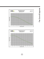
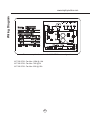
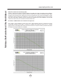
Fan Curve Diagrams
www.zephyronline.com
ALUÀRZ&RQWURO7HFKQRORJ\$&7
Some local codes limit the maximum amount of CFM a range hood can move. ACT allows you to
control the maximum blower CFM of hoods with Zephyr’s DCBL Suppression System without the need
for expensive make up air kits. ACT enables the installer to easily set the maximum blower speed to
RQHRIWKUHHPRVWFRPPRQO\VSHFL¿HG&)0OHYHOVRU&)07KHXVDJHRI$&7PD\QRWEH
necessary for your installation. Please check your local codes for CFM restrictions.
By default the maximum blower CFM is set to 715.
7RYHULI\LI\RXULQVWDOOHUHQDEOHG$&7:LWKKRRGRIISUHVVDQGKROGWKHSRZHUEXWWRQIRUWKUHHVHFRQGV
Blower CFM will be displayed on the LCD screen. There should also be a foil label located inside the
hood body near the wiring diagram that indicates the blower CFM.
18
19
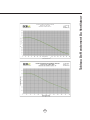
Fan Curve Diagrams
Wiring Diagram
www.zephyronline.com
Model:
ZML-M90BG/M90BS
ZML-E42BG/E42BS
Voltage 120V 60Hz
Power consumption
Total: Max. 215W @ 4A
Lamp:
Max. 3Wx4
Fan:
Max. 203W
THERMALLY PROTECTED
U
V
W
U
V
W
5A 250V
AC-N
ON/OFF DOWN
UP
AC-L
LAMP
3RZHUFRQVXPSWLRQVKRZQIRUGHIDXOW&)0EORZHUFRQ¿JXUDWLRQ
ACT 590 CFM - Fan Max. 130W @ 1.8A
ACT 390 CFM - Fan Max. 70W @ 1A
ACT 290 CFM - Fan Max. 35W @ .55A
20
PART#
Replacement Parts
Light Bulb, LED 3W
Z0B-0032
Aluminum Mesh Filter
50200043
Optional Accessories
Recirculating Kit
ZRC-00ML
Replacement Charcoal Filter
Z0F-C002
'XFW&RYHU([WHQVLRQXSWR¶FHLOLQJ
=&0/
Gray Glass Canopy 90cm
ZMG-03GY
Gray Glass Canopy 42”
ZMG-04GY
To order parts, visit us online at http://store.zephyronline.com or call us at 1.888.880.8368
21
List of Parts & Accessories
DESCRIPTION
STAPLE YOUR RECEIPT HERE
Proof of the original purchase
date is needed to obtain
service under warranty
Limited Warranty
TO OBTAIN SERVICE UNDER WARRANTY OR FOR ANY SERVICE RELATED QUESTIONS, please call:
1-888-880-8368
Zephyr Corporation (referred to herein as “we” or “us”) warrants to the original consumer purchaser (referred to herein
as “you” or “your”) of Zephyr products (the “Products”) that such Products will be free from defects in materials or workmanship as follows:
Three Year Limited Warranty for Parts: For three years from the date of your original purchase of the Products, we
will provide, free of charge, Products or parts (including LED light bulbs, if applicable) to replace those that failed due to
manufacturing defects. We may choose, in our sole discretion, to repair or replace parts before we elect to replace the
Products.
One Year Limited Warranty for Labor: For one year from the date of your original purchase of the Products, we will
provide, free of charge, the labor cost associated with repairing the Products or parts to replace those that failed due to
manufacturing defects. After the first year from the date of your original purchase, you are responsible for all labor costs
associated with this warranty.
Warranty Exclusions: This warranty covers only repair or replacement, at our option, of defective Products or parts
and does not cover any other costs related to the Products including but not limited to: (a) normal maintenance and
service required for the Products and consumable parts such as incandescent or halogen light bulbs, metal and carbon
filters and fuses; (b) any Products or parts which have been subject to freight damage, misuse, negligence, accident,
faulty installation or installation contrary to recommended installation instructions, improper maintenance or repair (other
than by us); (c) commercial use of the Products or use otherwise inconsistent with its intended purpose; (d) natural wear
of the finish of the Products or wear caused by improper maintenance, use of corrosive and abrasive cleaning products,
pads, and oven cleaner products; (e) chips, dents or cracks caused by abuse or misuse of the Products; (f) service trips
to your home to teach you how to use the Products; or (g) damage to the Products caused by accident, fire, floods or act
of God. If you are outside our service area, additional charges may apply for shipping costs for warranty repair at our
designated service locations and for the travel cost to have a service technician come to your home to repair, remove or
reinstall the Products. After the first year from the date of your original purchase, you are also responsible for all labor
costs associated with this warranty.
Limitations of Warranty. OUR OBLIGATION TO REPAIR OR REPLACE, AT OUR OPTION, SHALL BE YOUR SOLE
AND EXCLUSIVE REMEDY UNDER THIS WARRANTY. WE SHALL NOT BE LIABLE FOR INCIDENTAL, CONSEQUENTIAL OR SPECIAL DAMAGES ARISING OUT OF OR IN CONNECTION WITH THE USE OR PERFORMANCE OF
THE PRODUCTS. THE EXPRESS WARRANTIES IN THE PRECEDING SECTION ARE EXCLUSIVE AND IN LIEU OF
ALL OTHER EXPRESS WARRANTIES. WE HEREBY DISCLAIM AND EXCLUDE ALL OTHER EXPRESS WARRANTIES FOR THE PRODUCTS, AND DISCLAIM AND EXCLUDE ALL WARRANTIES IMPLIED BY LAW, INCLUDING
THOSE OF MERCHANTABILITY AND FITNESS FOR A PARTICULAR PURPOSE. Some states or provinces do not
allow limitations on the duration of an implied warranty or the exclusion or limitation of incidental or consequential damages, so the above limitations or exclusions may not apply to you. To the extent that applicable law prohibits the exclusion of implied warranties, the duration of any applicable implied warranty is limited to the same two-year period
described above. Any oral or written description of the Products is for the sole purpose of identifying the Products and
shall not be construed as an express warranty. Prior to using, implementing or permitting use of the Products, you shall
determine the suitability of the Products for the intended use, and you shall assume all risk and liability whatsoever in
connection with such determination. We reserve the right to use functionally equivalent refurbished or reconditioned
parts or Products as warranty replacements or as part of warranty service. This warranty is not transferable from the
original purchaser and applies in the United States and Canada.
To Obtain Service Under Limited Warranty: To qualify for warranty service, you must: (a) notify us at the address or
telephone number stated below within 60 days of the discovery of the defect; (b) give the model number and part identification number and serial number; and (c) describe the nature of any defect in the Product or part. At the time of the
request for warranty service, you must present evidence of your proof of purchase and proof of the original purchase
date. If we determine that the warranty exclusions listed above apply or if you fail to provide the necessary documentation to obtain service, you will be responsible for all shipping, travel, labor and other costs related to the services.
Please check our website for any revisions, www.zephyronline.com.
MAY13.0301
Guide d’utilisation, d’entretien et d’installation
www.zephyronline.com
Milano Island
ZML-M90BG
ZML-M90BS
ZML-E42BG
ZML-E42BS
Numéro de modèle : _________________
Numéro de série :
_________________
+
APR14.0701 © Zephyr Corporation
Pour une utilisation avec des modèles de numéros de
série commençant par 21
C
TM
Airflow Control Technology
www.zephyronline.com
INSTALLATION
Feuille de calcul pour le conduit ...........................
Espace libre et hauteur de montage ...................
Options d’installation pour le conduit ..................
6SpFL¿FDWLRQVGHODKRWWH.........................................
Montage de la hotte ...................................................
Reprise d’air sans conduit .......................................
5
6
7
8
9-12
13
COMMANDES
&RPPDQGHVjHIÀHXUHPHQW.................................. 14
Interface utilisateur ......................................... 15
ENTRETIEN
1HWWR\DJHGHV¿OWUHVHWGHODKRWWH ...................... 16
DÉPANNAGE
................................................................................
17
TABLEAU DE RENDEMENT DU VENTILATEUR ......... 18-19
SCHÉMA DE CÂBLAGE ........................................................... 20
LISTES DES ACCESSOIRES ET DES PIÈCES ............ 21
1
Table des matières
MISE EN GARDE DE SÉCURITÉ.......................... 2-3
LISTE DU MATÉRIEL ....................................................... 4
Mise en garde de sécurité
LISEZ ET CONSERVEZ CES INSTRUCTIONS
www.zephyronline.com
AVERTISSEMENT
POUR RÉDUIRE LES RISQUES D’INCENDIE OU DE DÉCHARGE ÉLECTRIQUE, N’UTILISEZ PAS CET APPAREIL AVEC UN TABLEAU
DE COMMANDE À SEMI-CONDUCTEURS.
AVERTISSEMENT
POUR RÉDUIRE LES RISQUES D’INCENDIE, DE DÉCHARGE ÉLECTRIQUE OU DE BLESSURE, RESPECTEZ CES CONSIGNES :
a. N’utilisez cet appareil que de la manière prévue par le fabricant. Si vous avez des questions, communiquez avec le fabricant.
b. Avant de procéder au nettoyage ou à l’entretien de l’appareil, éteignez l’alimentation du panneau électrique et bloquez le dispositif de
déconnexion pour éviter que l’alimentation électrique ne soit accidentellement rallumée. Si le dispositif de sectionnement d’électricité ne peut
être bloqué, attachez un avertissement (comme une étiquette) bien en vue sur le tableau électrique.
ATTENTION
Pour ventilation générale seulement. N’utilisez pas cet appareil pour évacuer des vapeurs et des matériaux explosifs ou dangereux. Prenez garde
lors de l’utilisation d’agents nettoyants ou de détergents. Ne devrait être utilisé que dans la cuisine de votre maison.
AVERTISSEMENT
POUR RÉDUIRE LES RISQUES DE FEU DE GRAISSE SUR LA SURFACE DE CUISSON :
a. Ne laissez jamais l’appareil sans surveillance lors de son utilisation à haute température. Les débordements par bouillonnement causent de la
fumée et des déversements de graisse qui peuvent prendre feu. Faites chauffer l’huile à des températures basses ou moyennes.
E $OOXPH]WRXMRXUVODKRWWHORUVTXHYRXVFXLVLQH]jKDXWHWHPSpUDWXUHRXTXHYRXVIDLWHVÀDPEHUGHVDOLPHQWV
F 1HWWR\H]IUpTXHPPHQWOHVYHQWLODWHXUVGHODKRWWH/DJUDLVVHQHGHYUDLWMDPDLVV¶DFFXPXOHUGDQVOHVYHQWLODWHXUVRXOHV¿OWUHV
d. Utilisez des poêlons aux dimensions adéquates. Utilisez toujours une batterie de cuisine correspondant aux dimensions de l’élément.
H $VVXUH]YRXVTXHOHYHQWLODWHXUOHV¿OWUHVHWOHVVXUIDFHVRODJUDLVVHSRXUUDLWV¶DFFXPXOHUVRQWWRXMRXUVSURSUHV
f. Utilisez le réglage haut de la hotte seulement lorsque nécessaire.
g. Ne laissez pas la hotte sans surveillance lorsque vous cuisinez.
h. Utilisez toujours une batterie de cuisine et des ustensiles convenant au type et à la quantité de nourriture que vous préparez.
AVERTISSEMENT
POUR RÉDUIRE LES RISQUES DE BLESSURE LORS D’UN INCENDIE SUR LA SURFACE DE CUISSON :
a. ÉTOUFFEZ LES FLAMMES avec un couvercle, une plaque à biscuits ou un plateau de métal et éteignez ensuite le brûleur. PRENEZ GARDE
$8;5,648(6'(%5Ó/85(6LOHVÀDPPHVQHGLVSDUDLVVHQWSDVe9$&8(=/(6/,(8;(7$33(/(=/(6(59,&('¶,1&(1',(
b. NE PRENEZ JAMAIS UN POÊLON EN FEU – Vous pourriez vous brûler.
c. N’UTILISEZ PAS D’EAU, ou un linge à vaisselle mouillé – une violente explosion de vapeur s’ensuivra.
d. Utilisez un extincteur SEULEMENT si :
1. Vous savez que vous possédez un extincteur de classe ABC et vous savez vous en servir.
2. Le feu est faible et ne s’est pas répandu depuis son point d’origine.
3. Vous avez appelé le service d’incendie.
9RXVSRXYH]VRUWLUIDFLOHPHQWGHO¶HQGURLWRYRXVFRPEDWWH]OHIHX
AVERTISSEMENT
POUR RÉDUIRE LES RISQUES D’INCENDIE, DE DÉCHARGE ÉLECTRIQUE OU DE BLESSURE, SUIVEZ LES CONSIGNES SUIVANTES :
D /HVWUDYDX[G¶LQVWDOODWLRQHWGHFkEODJHpOHFWULTXHGRLYHQWrWUHIDLWVSDUXQHSHUVRQQHTXDOL¿pHVHORQOHVVWLSXODWLRQVGHWRXVOHVQRUPHVHW
standards en vigueur, dont les normes des constructions ayant une cote de résistance au feu.
b. Pour prévenir les contre-explosions, une certaine quantité d’air est nécessaire pour la combustion et l’évacuation des gaz par le carneau
(cheminée) de l’appareil de combustion. Respectez les directives du fabricant d’outillage de chauffage et les normes de sécurité comme celles
publiées par la NFPA (Association nationale des services d’incendie), par la Société américaine des ingénieurs en chauffage, réfrigération et
climatisation (ASHRAE) et par les normes des autorités locales.
c. Lorsque vous coupez ou percez un mur ou un plafond, assurez-vous de ne pas endommager le câblage électrique ou toute autre installation
technique dissimulée.
d. Les ventilateurs canalisés doivent toujours évacuer l’air à l’extérieur.
e. Si l’appareil est installé près d’une baignoire ou d’une douche, il doit être désigné convenablement pour cette application et être branché à un
disjoncteur de fuite de terre.
f. N’installez JAMAIS un interrupteur à une distance atteignable depuis un bain ou une douche.
g. Assurez-vous que l’alimentation électrique est éteinte avant de procéder à l’installation, au câblage ou à l’entretien de l’appareil
2
POUR RÉDUIRE LES RISQUES D’INCENDIE, N’UTILISEZ QUE DES CONDUITS D’AÉRATION EN MÉTAL.
CET APPAREIL N’EST PAS CONÇU POUR ÊTRE UTILISÉ À L’EXTÉRIEUR.
ATTENTION
Pour réduire les risques d’incendie et pour évacuer l’air convenablement, assurez-vous de canaliser l’air à l’extérieur de
la maison. N’installez pas l’échappement du conduit dans les espaces entre les murs, le plafond, le grenier, les vides
sanitaires ou le garage.
FONCTIONNEMENT
/DLVVH]WRXMRXUVOHVJULOOHVGHVUHWpHWOHV¿OWUHVHQSODFH6DQVFHVpOpPHQWVOHVYHQWLODWHXUVHQPDUFKHSRXUUDLHQW
accrocher des cheveux, des doigts ou des vêtements amples.
Le fabricant se dégage de toute responsabilité dans les cas de non-respect des instructions transmises dans le présent
manuel pour l’installation, l’entretien et l’utilisation adéquate du produit. Le fabricant se dégage également de toute
UHVSRQVDELOLWpSRXUGHVEOHVVXUHVTXLUpVXOWHUDLHQWGHODQpJOLJHQFHORUVGHO¶XWLOLVDWLRQ'HSOXVODJDUDQWLHSUHQG¿Q
automatiquement lors de l’entretien inapproprié de l’appareil.
*NOTE : Veuillez communiquer avec nous ou visitez le www.zephyronline.com pour obtenir des révisions avant de
procéder à des travaux sur commande.
EXIGENCES ÉLECTRIQUES
Important :
Respectez tous les codes et règlements en vigueur.
Il est de la responsabilité du client de :
&RPPXQLTXHUDYHFXQLQVWDOODWHXUpOHFWULFLHQTXDOL¿p
- S’assurer que l’installation électrique est adéquate et qu’elle respecte le Code national de l’électricité, la plus récente
édition* du ANSI/NFPA 70 ou des normes du CSA C22.1-94, le Code canadien de l’électricité, section 1, la plus récente
édition** du code C22.2 No.0-M91 ainsi que tous les codes et réglements en vigueur.
6LOHVFRGHVSHUPHWWHQWO¶XWLOLVDWLRQG¶XQ¿OGHJDUGHLVROpHWTXHYRXVHQXWLOLVH]XQLOHVWUHFRPPDQGpTX¶XQpOHFWULFLHQ
TXDOL¿pGpWHUPLQHVLOHFKHPLQHPHQWGX¿OHVWDGpTXDW
N’effectuez pas la mise à la terre à un tuyau de gaz.
'HPDQGH]jXQpOHFWULFLHQTXDOL¿pVLYRXVQ¶rWHVSDVFHUWDLQTXHODKRWWHDpWpPLVHjODWHUUHDGpTXDWHPHQW
N’introduisez aucun fusible dans le circuit neutre ou de mise à la terre.
*National Fire Protection Association Batterymarch Park, Quincy, Massachusetts 02269
** CSA International 8501 East Pleasant Valley Road, Cleveland, Ohio 44131-5575
Cet appareil requiert une alimentation électrique de 120V 60Hz. Il doit être connecté à un circuit terminal individuel
dûment mis à la terre, protégé par un disjoncteur de circuit ou un fusible temporisé de 15 ou 20 ampères. Le câblage doit
FRPSWHU¿OVDYHFPLVHjODWHUUH9HXLOOH]YRXVUpIpUHUDX'LDJUDPPHpOHFWULTXHpWLTXHWpVXUO¶DSSDUHLO
Un raccord de câble (non inclus) pourrait également être exigé par les normes et réglementations locales. Informez-vous
des exigences et des normes locales. Achetez et installez le connecteur approprié si nécessaire.
ZML-M90BG/BS – MAX 215 Watts, 4 Ampères
ZML-E42BG/BS – MAX 215 Watts, 4 Ampères
&RQVRPPDWLRQFLGHVVXVHVWGHVVSpFL¿FDWLRQVG¶DOLPHQWDWLRQSDUGpIDXW+RWWHVDYHF=HSK\UWHFKQRORJLHpFRXOHPHQW
G¶DLUGHFRQWU{OHH[FOXVLI$&7DSHUPLVFRQVRPPHPRLQVG¶pQHUJLH9RLUOHVFKpPDGHFkEODJHjOD¿QGHFHPDQXHO
pour plus d’informations.
3
Mise en garde de sécurité
ATTENTION
Liste du matériel
www.zephyronline.com
MODÈLES : ZML-M90BG/BS , ZML-E42BG/BS
PIÈCES FOURNIES
1 - Cadre de fixation supérieur
Devant de la hotte
L/C
B
Zone de découpage ombragée
2 - Pièces de recouvrement
supérieures pour le conduit
2 - Pièces d’habillage larges
1 - Gabarit de
plafond en papier
A
1 - Support de cadre de fixation
2 - Pièces de recouvrement
inférieures pour le conduit
2 - Pièces d’habillage minces
1 - Cadre de fixation inférieur
1 - Registre circulaire de 8” (préinstallé)
1 - Boîtier de la hotte avec ventilateur (préinstallé)
2 - Support de fixation
1 - Pavillon, verre ou inox
4 - Ampoules DEL 3W
2 - Filtres à tamis en aluminium
1 - Trousse de quincaillerie
CONTENU DE LA TROUSSE DE QUINCAILLERIE
(3) Capuchons de
(4) M6 x 1 -1/2”
(14) v M3 x 5
connexion
(vis à bois)
(vis pour recourvrement
de conduit)
(4) 3/16 x 1/4
(vis pour pavillon)
(1) M4 x 12
(vis de sûreté)
(20) M4 x 8
PIÈCES NON FOURNIES
- Conduit et tous les outils d’installation
- Raccord de câble (si exigé par les codes en vigueur)
- Accessoire – prolongement pour recouvrement de conduit
- Accessoire – reprise d’air
4
(4) rondelles
ø12 OD / ø5 ID
(2) M4 x 8
Equivalent number
length x used
=
Duct pieces
Total
Total
3-1/ 4” x 10” 1 Ft.
Rect.,
straight
x(
) =
Ft.
6”- 8” Round 30 Ft.
wall cap
with damper
x(
) =
Ft.
7” Round,
straight
1 Ft.
x(
) =
Ft.
6”- 8” Round, 30 Ft.
roof cap
x(
) =
Ft.
8” Round,
straight
1 Ft.
x(
) =
Ft.
6” round to
1 Ft.
3-1/ 4” x 10”
rect.
transition
x(
) =
Ft.
3-1/ 4” x 10” 15 Ft.
Rect. 90 0
elbow
x(
) =
Ft.
x(
) =
Ft.
3-1/ 4” x 10” 9 Ft.
Rect. 45 0
elbow
x(
) =
Ft.
6” round to
16 Ft.
3-1/ 4” x 10”
rect.
transition
90 0 elbow
7” or 8”
Round,
90 0 elbow
15 Ft.
x(
) =
Ft.
3-1/ 4” x 10” 24 Ft.
Rect. 90 0
flat elbow
x(
7” or 8”
Round,
45 0 elbow
9 Ft.
x(
) =
Ft.
3-1/ 4” x 10” 30 Ft.
Rect.
wall cap
with damper
x(
7” or 8”
30 Ft.
Round
wall cap
with damper
x(
) =
Ft.
3-1/ 4” x 10” 5 Ft.
Rect. to
6” round
transition
x(
) =
Ft.
7” or 8”
Round,
roof cap
x(
) =
Ft.
3-1/ 4” x 10” 20 Ft.
Rect. to
6” round
transition
90 0 elbow
x(
) =
Ft.
7” round to
8 Ft.
3 1/ 4” x 10”
rect.
transition
x(
) =
Ft.
) =
Ft.
15 Ft.
x(
) =
Ft.
7” round to
23 Ft.
3-1/ 4” x 10”
rect.
transition
90 0 elbow
x(
6” Round,
90 0 elbow
6” Round,
45 0 elbow
9 Ft.
x(
) =
Ft.
Subtotal column 2 =
Ft.
Subtotal column 1 =
Ft.
Total ductwork
Ft.
) =
) =
Subtotal column 1 =
Ft.
Ft.
Ft.
Longueur maximale du conduit d’aération : Pour un
mouvement d’air convenable, la longueur totale d’un conduit
d’aération ne devrait pas compter plus que l’équivalent
de 100 pieds.
5
30 Ft.
=
Installation – Feuille de calcul pour le conduit d’aération
Equivalent number
length x used
=
Duct pieces
Installation – Espace libre et hauteur de montage
www.zephyronline.com
être moins de 26”.
La hauteur de montage maximale ne devrait pas
outrepasser 34”.
Il est important d’installer la hotte à la hauteur
de montage adéquate. Les hottes installées
trop basses pourraient être endommagées par
la chaleur en plus de présenter des risques
d’incendie plus élevés tandis que les hottes
LQVWDOOpHVWURSKDXWHVVHURQWGLI¿FLOHVjDWWHLQGUH
HWYHUURQWOHXUHI¿FDFLWpHWOHXUUHQGHPHQWUpGXLWV
A
n.
mi . B
n
mi . C
x
ma
D
n.
mi . E
n
i
m .F
x
ma
in.
” m x.
26” ma
34
Si elles sont disponibles, consultez les exigences
de hauteur d’espace libre requise par le fabricant
de la cuisinière ainsi que la hauteur recommandée
de montage de la hotte au-dessus de la surface
de cuisson. Informez-vous toujours des normes et
des réglementations locales en vigueur pour toute
différence par rapport aux normes du fabricant.
”
36
Ensemble de recouvrement de conduit disponible
pour les plafonds atteignant 12 pieds. Numéro de
pièce et information pour commander disponibles
à la page 21.
Hauteur de la hotte
Recouvrement de Prolongement de
recouvrement de
conduit standard conduit
minimum avec conduit (A) 28 1/2”
minimum avec reprise d’air (B) 32 1/2”
maximum (C) 50”
44“
48 1/2“
82”
ENDOMMAGEMENT LORS DE LA LIVRAISON/
INSTALLATION :
9HXLOOH]YRXVDVVXUHUTXHWRXWHVOHVSLqFHV
de l’appareil ne sont pas endommagées avant
l’installation.
Hauteur de plafond
minimum avec conduit (D) 90 1/2” (7’ 6 1/2”) 106“ (8‘ 10”)
minimum avec reprise d’air (E) 94 1/2” (7’10 1/2”) 113“ (9‘ 5”)
maximum (F) 120” (10’)
150” (12’ 8”)
Un conduit circulaire de 8” doit être utilisé pour
assurer une circulation d’air maximale.
6LO¶DSSDUHLOHVWHQGRPPDJpGXUDQWODOLYUDLVRQ
UHWRXUQH]O¶DSSDUHLOjO¶HQGURLWRYRXVO¶DYH]
acheté pour réparation ou remplacement.
N’utilisez que des conduits en métal rigide. Les
conduits souples pourraient réduire la circulation
d’air jusqu’à 50 %.
6LO¶DSSDUHLOHVWHQGRPPDJpSDUOHFOLHQWOD
réparation ou le remplacement est à la charge du
client.
Utilisez la feuille de calcul pour obtenir la longueur
totale du conduit (page 5).
6LO¶DSSDUHLOHVWHQGRPPDJpSDUO¶LQVWDOODWHXU
(si autre que le client), le client et l’installateur
doivent en venir à une entente pour la réparation
ou le remplacement.
CONDUIT D’AÉRATION
Lorsqu’il est possible de le faire, diminuez
TOUJOURS le nombre de pièces et de
changements de direction. Si un long tronçon de
conduit est nécessaire, augmentez le diamètre du
conduit de 8” à 10”.
Si des changements de direction ou des
adaptateurs sont nécessaires, installez-les le
plus loin possible de l’ouverture et le plus éloigné
possible l’un de l’autre.
La hauteur de montage minimale ne devrait pas
6
N’évacuez ou ne terminez JAMAIS l’échappement du conduit dans les espaces entre les murs, les vides
sanitaires, le plafond, le grenier, ou le garage. Tous les échappements doivent être dirigés à l’extérieur de la
maison, à moins que l’option de reprise d’air ne soit utilisée.
N’utilisez que des conduits en métal pour cloison simple.
Fixez toutes les pièces du conduit avec des vis à tôle et isolez tous les joints avec du ruban adhésif en toile ou
GXUXEDQUpÀHFWHXUFHUWL¿p
Pente de la toiture
avec solin et chapeau
(Boîtier de
ventilateur)
(Boîtier de
ventilateur)
Bouche d’aération de
mur latéral avec clapet
antirefoulement
Retombée de plafond ou vide sanitaire
(Boîtier de
ventilateur)
Reprise
d’air sans conduit
7
Installation – Options pour le conduit d’aération
AVERTISSEMENT DE RISQUE D’INCENDIE
12 15/16”
12 3/4”
9 11/16”
6 11/16”
STANDARD
Min. avec conduit - 28 1/2”
Min. avec reprise d’air - 32 1/2”
max. - 50”
14 1/8”
Z1C-03ML
Min. avec conduit - 44”
Min. avec reprise d’air - 48 1/2”
max. - 82”
23 15/16”
35 5/16”, 42”
25 9/16”
DEVANT
CÔTÉ
10 9/16”
9 11/16”
1 1/4”
L/C
L/C
4”
Entrée CA
71
10 15/16”
L/C
5/1
6”
2 3/16”
5 5/16”
4 13/16”
5/8”
Installation – 6SpFL¿FDWLRQVGHODKRWWH
www.zephyronline.com
CADRE de FIXATION SUPÉRIEUR
DESSUS de la HOTTE
(vue du haut)
8
GABARIT EN PAPIER
Devant de la hotte
Solives de plafond
Bloc de bois
1
fron
t
3
Cadre de fixation supérieur
2
),*%
Cadre de fixation inférieur
6
5
Boîtier/pavillon de la hotte
4
),*$
/DKRWWHHVWFRQoXHSRXUrWUHLQVWDOOpHjXQSODIRQG¿QL
1. 3UpSDUDWLRQGXSODIRQG Déterminez l’emplacement pour l’installation de la hotte et collez temporairement le gabarit
en papier (inclus avec la hotte) au plafond. Dans le plafond, faites un trou correspondant à la zone interne ombragée
du gabarit. C’est là que passeront le conduit et les câbles électriques. Ajoutez les blocs de bois (min. 2” x 4”) aux
solives de plafond, sur la cloison sèche, pour renforcer le plafond (FIG. A#1). Fixez deux vis à bois 1-1/2” aux points
A et B du gabarit en papier (FIG. B). Ne serrez pas les vis jusqu’au bout et laissez dépasser environ 1/4”.
2. 3UpSDUDWLRQ GH OD KRWWH (QOHYH] OHV YLV TXL UHWLHQQHQW OHV FDGUHV GH ¿[DWLRQ VXSpULHXU HW LQIpULHXU HQVHPEOH
$MXVWH]OHFDGUHGH¿[DWLRQVHORQODKDXWHXUG¶LQVWDOODWLRQGpVLUpHGHODKRWWHHWUpDVVHPEOH]OHFDGUHHQXWLOLVDQWOHV
YLVTXHYRXVDYH]SUpDODEOHPHQWHQOHYpHVGHX[YLVSRXUFKDTXHEUDVGHVFDGUHVGH¿[DWLRQ),*$
9
Installation – 0RQWDJHGHODKRWWH
! AVERTISSEMENT : Le câblage électrique doit être effectué par une ou
des personnes qualifiées selon les stipulations de tous les normes et
standards en vigueur. Éteignez l’alimentation électrique à l’entrée de
service avant de procéder au câblage.
Installation – 0RQWDJHGHODKRWWH
www.zephyronline.com
),*&
FRONT
FRONT
1
2
),*'
'HVSDWWHVGHVXSSRUWODWpUDOHVGRLYHQWrWUH¿[pHVDX[GHX[EUDVGX
FDGUHGH¿[DWLRQVXSpULHXUHWDX[EUDVFRUUHVSRQGDQWVGXFDGUHGH
¿[DWLRQLQIpULHXUSRXUOHVKRWWHVLQVWDOOpHVjXQHKDXWHXUGHj
pouces. Fixez les pattes de support latérales à l’aide de douze vis à
tôle M4 x 8. (FIG. C)
'HV SDWWHV GH VXSSRUW FDUUpHV GRLYHQW rWUH ¿[pHV j O¶LQWpULHXU GX
FDGUH GH ¿[DWLRQ SRXU OHV KRWWHV LQVWDOOpHV j XQH KDXWHXU GH j
50 pouces. Fixez les pattes de support carrées aux bras du cadre
GH¿[DWLRQVXSpULHXUjO¶DLGHGHKXLWYLVjW{OH0[),*(QR
/HVEUDVGXFDGUHGH¿[DWLRQVXSpULHXUGpSDVVHQWGHVVXSSRUWVGX
FDGUHGH¿[DWLRQLQIpULHXUORUVTXHODKRWWHHVWLQVWDOOpHjXQHKDXWHXU
moindre (FIG. E, no 2).
),*(
6RXOHYH] O¶DVVHPEODJH GHV FDGUHV GH ¿[DWLRQ YHUV OH SODIRQG HQ YRXV DVVXUDQW TXH OH PRW © )URQW ª VLWXp VXU
OHGHVVXVGHVFDGUHVGH¿[DWLRQHVWVXUODPrPHIDFHGHODKRWWHROHVFRPPDQGHVVRQWVLWXpHV),*'/HV
HQFRFKHV HQ WURX GH VHUUXUH VLWXpHV VXU OH GHVVXV GX FDGUH GH ¿[DWLRQ GHYUDLHQW FRwQFLGHU DYHF OHV YLV j ERLV
SUpDODEOHPHQW¿[pHVDXSODIRQG)DLWHVJOLVVHUOHFDGUHGH¿[DWLRQYHUVODSDUWLHpWURLWHGHVHQFRFKHVHQWURXGH
VHUUXUHSRXUOH¿[HUHQSODFH
,QVWDOOH]OHVGHX[GHUQLqUHVYLVjERLV´GDQVOHVGHX[FRLQVUHVWDQWVGXFDGUHGH¿[DWLRQVXSpULHXUSRXUOH¿[HU
solidement au plafond. Serrez les vis.
10
Boîtier de
ventilateur
SUPPORT DE
MONTAGE DU
DISPOSITIF
ÉLECTRONIQUE
),**
1
1
2
),*+
),*)
7. Enlevez le ruban qui retient le support de montage du dispositif électronique à la hotte (FIG. F#1). Enlevez
les trois vis du dessus du boîtier de la hotte et laissez-les de côté. Placez le support de montage du dispositif
pOHFWURQLTXHFRPPHLOOXVWUpVXU),*)HW¿[H]OHDXERvWLHUGHODKRWWHjO¶DLGHGHVWURLVYLVTXHYRXVDYH]
préalablement enlevées.
5HWLUH] OHV ¿OWUHV j WDPLV HQ DOXPLQLXP GH OD KRWWH 3ODFH] OH SDYLOORQ VXU OH ERvWLHU GX YHQWLODWHXU VLWXp VXU OH
GHVVXVGHODKRWWHHW¿[H]OHjODKRWWHjWUDYHUVO¶RXYHUWXUHGHV¿OWUHVjO¶DLGHGHTXDWUHYLV´[),**
Installez l’électricité et le conduit d’aération. Scellez le conduit avec du ruban à conduit en aluminium.
9. Soulevez le boîtier de la hotte et alignez les quatre vis de montage préinstallées sur le dessus du boîtier du
YHQWLODWHXU),*$jODSDJHGDQVOHVTXDWUHHQFRFKHVHQWURXGHVHUUXUHGXFDGUHGH¿[DWLRQLQIpULHXU),*
+)DLWHVOHJOLVVHUYHUVODSDUWLHpWURLWHGHVHQFRFKHVHQWURXGHVHUUXUHSRXUOH¿[HUHQSODFH6HUUH]FKDTXH
YLVjODPDLQSRXU¿[HUODKRWWHDXFDGUHGH¿[DWLRQLQIpULHXU)L[H]XQHYLVGHVUHWp0[PPDXFDGUHGH
¿[DWLRQLQIpULHXUSRXUXQHLQVWDOODWLRQSOXVVROLGHGHODKRWWH),*+
10. Installez l’électricité et le conduit d’aération. Scellez le conduit avec du ruban à conduit en aluminium.
0HWWH]ODKRWWHVRXVWHQVLRQSRXUYRXVDVVXUHUGXERQIRQFWLRQQHPHQWGHWRXWHVOHVIRQFWLRQVHWYpUL¿H]V¶LO\D
des fuites d’air autour du ruban à conduit.
11
Installation – 0RQWDJHGHODKRWWH
! ATTENTION : Compte tenu du poids
et des dimensions de la hotte, au moins
deux installateurs sont nécessaires.
Installation – 0RQWDJHGHODKRWWH
www.zephyronline.com
Coupez la pièce
d’habillage au besoin
1
Cadre de fixation
supérieur
Pièces de recouvrement
supérieures
2
5 Pièce d’habillage large (haut)
4 Pièce d’habillage mince (bas)
Pièces de recouvrement
inférieures
3
Cadre de fixation
inférieur
),* )L[H] OHV SLqFHV GH UHFRXYUHPHQW VXSpULHXUHV DYHF OHV WURXV SRXU GpÀHFWHXU DX FDGUH GH ¿[DWLRQ VXSpULHXU j O¶DLGH
de deux vis M4 x 8 (FIG. J#1). Note : Si vous utilisez la hotte en mode avec conduit, vous pouvez inverser les pièces de
UHFRXYUHPHQWSRXUFDFKHUOHVWURXVSRXUGpÀHFWHXUV
13. Assemblez les pièces de recouvrements supérieures à l’aide de trois vis M3 x 5 par côté (FIG. J#2). Les ouvertures à vis
plus grandes devraient chevaucher les plus petits trous.
14. Assemblez les pièces de recouvrements inférieures à l’aide de trois vis M3 x 5 par côté. Les pièces de recouvrements
inférieures reposeront sur la partie supérieure du boîtier de la hotte (FIG. J#3).
15. Insérez les deux pièces d’habillage minces dans les fentes de gauche et de droite des pièces de recouvrement inférieures
(une de chaque côté) (FIG. J#4).
16. Insérez les deux pièces d’habillage larges dans les fentes de gauche et de droite des pièces de recouvrement supérieures
(une de chaque côté) (FIG. J#5). Note : Puisqu’une moins grande partie des pièces de recouvrement supérieures
VHUDH[SRVpHYRXVSRXUULH]DYRLUjPHVXUHUHWjFRXSHUOHVSLqFHVG¶KDELOODJHODUJHVDYDQWGHOHVLQVpUHUGDQVOHV
SLqFHVGHUHFRXYUHPHQW
6LYRXVXWLOLVH]ODKRWWHHQPRGHGHUHSULVHG¶DLUYRXVGHYH]LQVWDOOHUOHGpÀHFWHXUDYDQWG¶DVVHPEOHUOHVSLqFHVGH
UHFRXYUHPHQW
&RQVXOWH]OHVLQVWUXFWLRQVjODSDJH
12
Nous recommandons de TOUJOURS évacuer l’air à l’extérieur de la maison en utilisant le conduit en place ou,
V¶LO\DSRVVLELOLWpHQLQVWDOODQWXQQRXYHDXFRQGXLW/DKRWWHHVWSOXVHI¿FDFHORUVTX¶XWLOLVpHFRPPHV\VWqPH
G¶pYDFXDWLRQ G¶DLU 9RXV QH GHYULH] UHFRXULU j OD FRQ¿JXUDWLRQ GH UHSULVH G¶DLU TXH ORUVTX¶LO HVW LPSRVVLEOH
d’installer un conduit d’aération.
/RUVTXH OD FRQ¿JXUDWLRQ GH UHSULVH G¶DLU HVW FKRLVLH XQ HQVHPEOH GH ¿OWUHV j FKDUERQ GRLW rWUH LQVWDOOp VXU
O¶HQVHPEOHGH¿OWUHVjWDPLVHQDOXPLQLXP&RPPDQGH]OHVHQYRXVUpIpUDQWDXQXPpURGHSLqFHFLGHVVRXV
/HV ¿OWUHV j WDPLV HQ DOXPLQLXP VRQW FRQoXV SRXU FDSWXUHU OHV UpVLGXV GH FXLVVRQ HW OHV ¿OWUHV j FKDUERQ
RSWLRQQHOVDLGHQWjODSXUL¿FDWLRQGHVYDSHXUVHWIXPpHVGHODFXLVVRQORUVGHODUHSULVHG¶DLU
ENSEMBLE DE REPRISE D’AIR (REQUIS SI AUCUN CONDUIT N’EST UTILISÉ
/¶HQVHPEOHFRPSUHQGGHV¿OWUHVjFKDUERQGHVVXSSRUWVGH¿OWUHVjFKDUERQHWXQGpÀHFWHXUG¶DLU
0RGqOHGHKRWWH 1XPpURGHSLqFH)LOWUHVSDUSDTXHW
ZML-M90BG/BS
ZRC-00ML
2
ZML-E42BG/BS
ZRC-00ML
2
1. Procurez-vous l’ensemble de reprise d’air en utilisant le numéro de pièce
ci-dessus
)L[H]OHGpÀHFWHXUDXPXUVRXVOHVXSSRUWPXUDOGHUHFRXYUHPHQWGH
conduit (FIG. K). Installez le conduit de 8” à la partie supérieure de la
KRWWHHW¿[H]OHjODSODTXHGXGpÀHFWHXUG¶DLU
5HWLUH]OHV¿OWUHVjWDPLVHQDOXPLQLXPGHODKRWWH,QVWDOOH]OHVXSSRUW
GHV¿OWUHVjFKDUERQGDQVO¶RXYHUWXUHGHV¿OWUHV1RWH/HVYLVTXLVHUYHQW
j¿[HUOHVXSSRUWGHV¿OWUHVjFKDUERQHQSODFHVRQWSUpLQVWDOOpHVGDQV
ODKRWWHHWGRLYHQWG¶DERUGrWUHHQOHYpHV)L[H]OHV¿OWUHVjFKDUERQDX
VXSSRUWGHV¿OWUHVjFKDUERQ),*.
5pLQVWDOOH]OHV¿OWUHVjWDPLVHQDOXPLQLXP
$OOXPH] O¶LQGLFDWHXU GH FKDQJHPHQW GX ¿OWUH j FKDUERQ VXU OH
panneau indicateur (consultez la page 15 pour plus de détails). Le
PLFURSURFHVVHXUGHVFRPPDQGHVYRXVLQGLTXHUDOHPRPHQWRFKDQJHU
OH¿OWUHjFKDUERQDSUqVKHXUHVG¶XWLOLVDWLRQFRQWLQXH&RPPDQGH]
GHV¿OWUHVjFKDUERQGHUHPSODFHPHQWHQFRQVXOWDQWODOLVWHFLGHVVRXV
Note : Consultez le manuel compris avec l’ensemble de reprise d’air
pour obtenir des instructions d’installation plus détaillées
)LOWUHVjFKDUERQGHUHPSODFHPHQW
0RGqOHGHKRWWH1XPpURGHSLqFH4XDQWLWpjFRPPDQGHU
ZML-M90BG/BS
Z0F-C002
2
ZML-E42BG/BS
Z0F-C002
2
NE NETTOYEZ PAS LES FILTRES À CHARBON. Vous pourriez avoir à
FKDQJHUOHV¿OWUHVjFKDUERQSOXVVRXYHQWVHORQYRVKDELWXGHVFXOLQDLUHV
13
),*.
Installation – Reprise d’air sans conduit
/D FRQ¿JXUDWLRQ GH UHSULVH VDQV FRQGXLW D pWp FRQoXH SRXU OHV DSSOLFDWLRQV R LO HVW LPSRVVLEOH G¶LQVWDOOHU
un conduit d’aération. Lorsque transformée, la hotte fonctionne comme une hotte de reprise d’air plutôt que
FRPPH XQ V\VWqPH G¶pYDFXDWLRQ G¶DLU /HV YDSHXUV HW IXPpHV GH FXLVVRQ VRQW DVSLUpHV HW ¿OWUpHV SDU XQ
HQVHPEOHRSWLRQQHOGH¿OWUHVjFKDUERQ/¶DLUHVWHQVXLWHSXUL¿pHWUHGLULJpjO¶LQWpULHXUGHODPDLVRQ
Commandes - &RPPDQGHVjHIÀHXUHPHQW
www.zephyronline.com
Touche de mise en
marche/arrêt automatique
Affichage (vitesse, arrêt automatique, nettoyage/changement des filtres, purification d’air)
clean mesh filter
clean air
replace charcoal filter
Choix de six vitesses
Lumières : Allumer/Veilleuse/Éteindre
1-Touche de mise en marche/arrêt automatique
Fonction de mise en marche
- La touche
permet d’allumer et d’éteindre la hotte (ventilateur et lumières).
- Lorsqu’elle est éteinte, la hotte garde en mémoire la dernière vitesse et le dernier niveau d’éclairage
(Exemple : Vous appuyez sur la touche
lorsque le ventilateur est à la vitesse 4 et que les lumières sont à haute
intensité. Si vous appuyez de nouveau sur la touche
pour allumer la hotte, le ventilateur se remet en marche à la vitesse 4
et les lumières s’allument à haute intensité).
Fonction d’arrêt automatique
- Appuyez sur le bouton et tenez-le enfoncé pendant deux secondes pour que le ventilateur s’allume à la vitesse 1. Le
symbole
s’illumine. Après cinq minutes, le ventilateur et les lumières s’éteignent automatiquement.
- Si vous appuyez sur le bouton
lorsque la fonction d’arrêt automatique est activée, la hotte s’éteint et annule la fonction
d’arrêt automatique.
Débit d'air contrôle de la technologie (ACT)
- ACT permet à l'utilisateur de contrôler le maximum CFM de la ventilateur.
- Pour vérifier le CFM du vos ventilateur:
- Avec la hotte désactivé, maintenez le bouton
pendant trois secondes. Le CFM de la ventilateur sera
affiché sur l'écran LCD.
2-Touche de choix de vitesse
Touche de réduction de la vitesse du ventilateur
- Appuyez sur ce bouton pour réduire la vitesse du ventilateur. 6 (Rafale), 5, 4, 3, 2, 1.
- Si le ventilateur est à la vitesse 1 lorsque vous appuyez sur cette touche, il s’éteint.
Touche d’augmentation de la vitesse du ventilateur
- Appuyez sur ce bouton pour augmenter la vitesse du ventilateur. 1, 2, 3, 4, 5, 6 (Rafale).
- Si la hotte est éteinte lorsque vous appuyez sur cette touche, le ventilateur s’allume à la vitesse 1.
Mode Rafale
- Cette vitesse est conçue pour changer l’air intensément et rapidement lorsqu’une grande quantité de fumée est générée.
Après trois minutes, le ventilateur passe automatiquement à la vitesse 5.
3-Touche des lumières
- Il y a deux intensités pour les lumières : haute et basse.
- Lorsqu’elles sont éteintes, appuyez une fois pour allumer les lumières à haute intensité. Les mots « lights hi » apparaissent
pendant deux secondes à l’écran LCD.
- Appuyez de nouveau pour les mettre à basse intensité. Les mots « lights lo » apparaissent pendant deux secondes sur l’écran
LCD.
- Appuyez encore une fois pour éteindre les lumières.
14
Indicateur de remplacement du filtre à charbon (désactivé par défaut, doit être activé avec le mode de reprise d’air)
- Pour activer la fonction de remplacement du filtre à charbon :
- Lorsque la hotte est éteinte, appuyez et tenez simultanément les touches
et
pendant trois secondes. Le
symbole
s’illumine pendant trois secondes, indiquant que la fonction de remplacement des filtres est activée.
- Pour désactiver la fonction de remplacement du filtre à charbon :
- Lorsque la hotte est éteinte, appuyez et tenez simultanément les touches
et
pendant trois secondes. Le
symbole
s’illumine pendant trois secondes puis s’éteint, indiquant que la fonction de remplacement des filtres est
désactivée.
- Après 120 heures d’utilisation du ventilateur, le symbole
et les mots « replace charcoal filter » s’illuminent, indiquant qu’il
est temps de remplacer les filtres à charbon. Le symbole et les mots resteront illuminés jusqu’à la réinitialisation de la fonction.
- Pour réinitialiser : Lorsque la hotte est éteinte, appuyez et tenez la touche
enfoncée pendant trois secondes. Après
trois secondes, le symbole
et les mots « replace charcoal filter » s’éteignent et le temporisateur de 120 heures est
réinitialisé.
Indicateur de purification d’air
- La fonction de purification d’air allume le ventilateur pour une période de dix minutes toutes les quatre heures pour enlever
l’air stagnant qui flotte dans la cuisine.
- Pour activer la fonction de purification d’air :
- Lorsque la hotte est éteinte, appuyez et tenez simultanément les touches
et
pendant trois
secondes. Le symbole
et les mots « clean air » s’illuminent et le ventilateur se met en marche à la
vitesse 1 pendant dix minutes. Après dix minutes, le ventilateur s’éteint et le temporisateur de quatre
heures est réinitialisé.
- Le symbole
reste illuminé lorsque la fonction de purification d’air est activée, même si le ventilateur
n’est pas allumé.
- Pour désactiver la fonction de purification d’air :
- Lorsque la hotte est éteinte, appuyez et tenez simultanément les touches
et
pendant trois
secondes jusqu’à ce que le symbole
s’éteigne.
- Lorsque la fonction de purification d’air est activée, le ventilateur fonctionne à la vitesse 1 pendant dix minutes toutes les
quatre heures, lorsque le ventilateur n’est pas utilisé. Après dix minutes, le ventilateur s’éteint et le temporisateur de quatre
heures est réinitialisé.
- Si l’utilisateur change la vitesse du ventilateur lorsque la fonction de purification d’air est en cours de marche, les mots «
clean air » s’éteignent, mais le symbole
reste illuminé. Si l’utilisateur appuie sur la touche , la période de quatre heures
est réinitialisée.
15
Installation – ,QWHUIDFHXWLOLVDWHXU
Indicateur de nettoyage des filtres à tamis (toujours en fonction)
- Après 30 heures d’utilisation du ventilateur, le symbole
et les mots « clean mesh filter » s’illuminent, indiquant qu’il est
temps de nettoyer les filtres à tamis. Le symbole et les mots restent illuminés jusqu’à la réinitialisation de la fonction.
- Pour réinitialiser : Lorsque la hotte est éteinte, appuyez et tenez la touche
enfoncée pendant trois secondes. Après
trois secondes, le symbole
et les mots « clean mesh filter » s’éteignent et le temporisateur de 30 heures est réinitialisé.
Entretien - 1HWWR\DJHGHODKRWWHHWGHV¿OWUHV
www.zephyronline.com
ENTRETIEN DES SURFACES:
Nettoyez régulièrement les surfaces de la hotte avec de l’eau savonneuse chaude et un chiffon de coton propre.
N’utilisez pas de détergent abrasif ou corrosif, de laines d’acier ou de tampons à récurer; ils égratigneront et
endommageront les surfaces.
Pour les taches plus tenaces, utilisez du produit dégraissant liquide.
Après le nettoyage, vous pouvez polir les surfaces avec des produits de polissage à acier inoxydable non
abrasifs pour redonner de l’éclat et du lustre aux surfaces. Frottez toujours doucement, avec un chiffon de coton
propre, et dans le sens du grain.
1¶XWLOLVH]SDVGHSURGXLWVjEODQFKLUDXFKORUHRXG¶DJHQWVQHWWR\DQWV©RUDQJHª
)LOWUHjWDPLVHQDOXPLQLXP
/HV¿OWUHVjWDPLVHQDOXPLQLXPLQVWDOOpVSDUOHIDEULFDQWRQWSRXUIRQFWLRQGH¿OWUHUOHVUpVLGXVHWODJUDLVVH
de cuisson. Ils ne nécessitent aucun remplacement sur une base régulière, mais doivent être gardés propres.
Enlevez-les et nettoyez-les à la main ou au lave-vaisselle avec de l’eau tiède. Vaporisez avec du détergent pour
graisse et laissez tremper pour éliminer la saleté accumulée.
6pFKH]OHV¿OWUHVHWUpLQVWDOOH]OHVDYDQWG¶XWLOLVHUODKRWWH
3RXUHQOHYHUOHV¿OWUHVjWDPLVHQDOXPLQLXP
1. Poussez sur les poignées à ressort
7LUH]VXUODSRLJQpHGX¿OWUHYHUVOHEDVSRXUHQOHYHU
OH¿OWUH
16
Problème
Cause
Solution
Après
l’installation,
l’appareil ne
fonctionne pas.
1. Le bloc d’alimentation n’est pas allumé
1. Assurez-vous que l’alimentation du disjoncteur
et de l’appareil est allumée
2. La ligne électrique et le raccord de câble ne sont
pas correctement branchés
9pUL¿H]TXHOHEUDQFKHPHQWGHO¶DSSDUHLODpWp
fait correctement
/HV¿OVpOHFWULTXHVGXWDEOHDXGHFRQWU{OHHWGH
commande sont débranchés
$VVXUH]YRXVTXHOHV¿OVpOHFWULTXHVHQWUHOHV
tableaux de contrôle et de commande sont
branchés convenablement
4. Tableau de contrôle/commande défectueux
4. Remplacez le tableau de contrôle/commande
1. Le moteur est défectueux, possiblement bloqué
1. Remplacez le moteur
2. Le système de protection thermale détecte que
le moteur est trop chaud pour fonctionner et
l’éteint.
2. Le moteur fonctionnera normalement lorsque
le système de protection thermale aura refroidi
3. Tableau de contrôle/commande défectueux
3. Remplacez la pièce défectueuse
Les lumières
fonctionnent,
mais le moteur
ne tourne pas.
/HPRWHXUQ¶HVWSDVELHQ¿[pHQSODFH
1. Fixez solidement le moteur en place
2. La roue du ventilateur est endommagée
2. Remplacez le ventilateur
/DKRWWHQ¶HVWSDVELHQ¿[pHHQSODFH
9pUL¿H]O¶LQVWDOODWLRQGHODKRWWH
4. Tableau de contrôle/commande défectueux
4. Remplacez la pièce défectueuse
Les niveaux
de vitesse de
ODVRXIÀHULHOH
même son.
1. Utilisation de la mauvaise taille de canalisation.
1. Changer le conduit à au moins 8 “ou plus.
$&7SHUPLVVRXIÀHULH&)0jRX&)0
2. Le niveau de bruit distinction entre certains
des vitesses peut être minime quand ACT
permis ventilateur est réglé à 290 ou 390
CFM.
Le moteur
fonctionne, mais
pas les lumières.
1. L’ampoule DEL est défectueuse
1. Remplacez l’ampoule DEL
/H¿OGHO¶DPSRXOH'(/HVWGHVVHUUp
%UDQFKH]OH¿OGHO¶DPSRXOH'(/
La hotte ne
fonctionne pas
bien.
1. La hotte est possiblement installée trop haut par
rapport à la cuisinière
1. Ajustez la distance entre la surface de la
cuisinière et la base de la hotte entre 26” et
34”
2. Du vent provenant d’une fenêtre ou d’une porte
ouverte avoisinante nuit à la ventilation
2. Fermez toutes les portes et fenêtres pour
éliminer les courants d’air
3. L’ouverture du conduit ou le conduit lui-même
est bloqué
3. Enlevez tout ce qui bloque l’ouverture ou le
conduit d’aération
L’appareil vibre.
4. L’ouverture du conduit est contre le vent
4. Ajustez l’orientation de l’ouverture du conduit
5. Mauvaises dimensions de conduit d’aération
5. Remplacez le conduit par un conduit adéquat
de 6” de diamètre ou plus pour le ventilateur
interne
/H¿OWUHHQPpWDO /H¿OWUHHQPpWDOHVWGHVVHUUp
vibre.
1. Assurez-vous que les attaches métalliques
de la poignée ne sont pas bloquées. Ou
UHPSODFH]OH¿OWUHjWDPLV
17
Dépannage
PROCÉDURES DE DÉPANNAGE POUR LA HOTTE MILANO ISLAND
Tableau De Rendement Du Ventilateur
www.zephyronline.com
'pELWG¶DLUFRQWU{OHGHODWHFKQRORJLH$&7
Certains codes locaux de limiter le montant maximum de CFM qu’une hotte de cuisinière peut se déplacer.
ACT vous permet de contrôler le maximum CFM de les hottes avec le système de répression DCBL à partir
de Zephyr sans avoir besoin de coûteux kits pour l’air de remplacement. ACT permet à l’installateur de régler
facilement la vitesse maximale du ventilateur à l’un des trois les plus couramment prescrits niveaux de CFM;
590, 390 ou 290 CFM. L’utilisation de l’ACT peut-être pas nécessaire pour votre installation. S’il vous plaît
YpUL¿H]YRVFRGHVORFDX[SRXUFRQQDvWUHOHVUHVWULFWLRQVGHV&)0
3DUGpIDXWOH&)0PD[LPDOHGXOHYHQWLODWHXUHVWUpJOpj
3RXU YpUL¿HU VL YRWUH LQVWDOODWHXU D SHUPLV $&7 $YHF OH KRWWH GpVDFWLYp DSSX\H] HW PDLQWHQH] OH ERXWRQ
G¶DOLPHQWDWLRQ SHQGDQW WURLV VHFRQGHV /H &)0 GX OH YHQWLODWHXU VHUD DI¿FKp VXU O¶pFUDQ /&' ,O \ D GHYUDLW
également être une étiquette feuille d’aluminium situé à l’intérieur du corps de la hotte à proximité de la schéma
de câblage qui indique le CFM du le ventilateur.
18
Debit (pi3/min)
19
Tableau De Rendement Du Ventilateur
Pression (en TQ)
Courbe de rendement du ventilateur, 390 CFM
Entree en CA: 120V, 60 Hz
Diametre du conduit de sortie : 8”
MOTEUR
CC
ZML-M90BG/M90BS
Modèle : ZML-E42BG/E42BS
BRANCHEMENT
DES COMMANDES
U
Total : Max. 215W @ 4A
Max. 3Wx4
Max. 203W
V
V
W
Lampe :
Ventilateur :
U
W
5A 250V
AC-N
AC-L
ON/OFF
BAS
HAUTLAMPE
&RQVRPPDWLRQPRQWUpSRXUGpIDXWGHFRQ¿JXUDWLRQGXYHQWLODWHXU&)0
ACT 590 CFM - Ventilateur Max. 130W @ 1.8A
ACT 390 CFM - Ventilateur Max. 70W @ 1A
ACT 290 CFM - Ventilateur Max. 35W @ .55A
20
VERT
BOÎTIER
CCI DES COMMANDES
PROTÉGÉ THERMIQUEMENT
NOIR
Tension : 120V 60Hz
Consommation d’énergie
DEL DEL DEL DEL
BLANC
6FKpPDGHFkEODJH
SCHÉMA DE CIRCUITS
Pièces de remplacement
Ampoule DEL 3W
Filtre à tamis en aluminium
Z0B-0032
50200043
Accessoires optionnels
Ensemble de reprise d’air
Filtre à charbon de remplacement
Ensemble de prolongement de recouvrement de conduit
(Pour des plafonds allant jusqu’à 12 pieds)
Pavillon en verre gris 90 cm
Pavillon en verre gris 42”
ZRC-00ML
Z0F-C002
Z1C-03ML
ZMG-03GY
ZMG-04GY
Pour commander des pièces, visitez-nous en ligne au www.zephyronline.com ou communiquez avec nous
par téléphone au 1-888-880-8368
21
Listes des pièces et des accessoires
NO DE PIÈCE
DESCRIPTION
AGRAFEZ VOTRE REÇU ICI
Garantie limitée
Une preuve de la date d’achat originale
est nécessaire pour obtenir du service
lorsque le produit est sous garantie
POUR OBTENIR DU SERVICE SOUS GARANTIE OU POUR TOUTE QUESTION LIÉE À L’ENTRETIEN,
veuillez communiquer avec nous au 1-888-880-8368
Zephyr Corporation (désigné aux présentes sous le nom de « nous ») garantit au premier acheteur (désigné aux présentes sous le nom de « vous » ou « votre ») de produits Zephyr (les « Produits ») que lesdits produits sont exempts de
défauts de fabrication ou de main-d’œuvre selon les conditions suivantes :
Garantie de trois ans sur les pièces : Garantie de trois ans à partir de la date d’achat originale du Produit. Nous
fournirons sans frais les Produits ou les pièces (y compris les ampoules LED, le cas échéant) de remplacement qui comportaient des défauts de fabrication. Nous pourrions choisir, à notre seule discrétion, de réparer ou de remplacer des
pièces avant de prendre la décision de remplacer le Produit.
Garantie limitée d’un an sur la main-d’œuvre : Garantie d’un an à partir de la date d’achat originale du Produit. Nous
couvrirons sans frais les frais de main-d’œuvre afférents à la réparation du Produit ou des pièces de remplacement qui
comportaient des défauts de fabrication. Un an après la date d’achat originale, vous serez responsable de tous les frais
de main-d’œuvre associés à la présente garantie.
Exclusions de la garantie : Cette garantie ne couvre que la réparation ou le remplacement, à notre gré, de pièces ou
de Produits défectueux et ne couvre aucun autre coût afférent aux Produits, dont, sans s’y limiter, les frais liés : (a) à
l’entretien normal des Produits et au remplacement des pièces consommables, comme les incandescence ou halogèneampoules, les filtres métalliques, les filtres à charbon et les fusibles; (b) à tout Produit ou pièce ayant été endommagé
durant le transport ou étant le résultat d’un mauvais usage, d’une négligence, d’un accident, d’une installation incorrecte
ou ne respectant pas les notices d’installation recommandées, d’un entretien ou d’une réparation inapproprié (dont ne
nous sommes pas responsables); (c) à une utilisation commerciale ou ne correspondant pas à l’utilisation pour laquelle
les Produits sont conçus; (d) à l’usure naturelle du fini, à l’usure due à un entretien inadéquat, à l’utilisation de produits
nettoyants corrosifs ou abrasifs, de tampons nettoyeurs et de produits de nettoyage pour le four; (e) aux éclats, entailles
ou fissures résultant d’un abus ou d’une mauvaise utilisation du Produit; (f) aux déplacement d’un technicien de service
à votre domicile pour vous montrer comment utiliser les Produits; (g) aux dommages causés par un accident, un
incendie, une inondation ou un cas fortuit. Si vous vous trouvez à l’extérieur du territoire que nous desservons, des frais
supplémentaires pourraient s’appliquer pour la livraison des produits à nos points de service désignés pour une réparation sous garantie ou vous pourriez avoir à débourser les frais de déplacement du technicien à votre domicile pour que
le Produit soit réparé, enlevé ou réinstallé. Un an après la date d’achat originale du Produit, vous êtes également
responsable de tous les frais de main-d’œuvre associés à la présente garantie.
Restrictions de la garantie. NOTRE OBLIGATION DE RÉPARER OU DE REMPLACER, À NOTRE GRÉ, LE PRODUIT
CONSTITUE VOTRE SEUL ET UNIQUE RECOURS SOUS LA PRÉSENTE GARANTIE. NOUS NE NOUS PORTONS
PAS RESPONSABLES POUR TOUT DOMMAGE INDIRECT, ACCESSOIRE OU PARTICULIER RÉSULTANT OU AYANT
UN LIEN AVEC L’UTILISATION OU LE RENDEMENT DES PRODUITS. LES GARANTIES EXPRESSES DE LA SECTION PRÉCÉDENTE SONT EXCLUSIVES ET TIENNENT LIEU DE TOUTE AUTRE GARANTIE EXPRESSE. PAR LES
PRÉSENTES, NOUS REJETONS ET EXCLUONS TOUTE AUTRE GARANTIE EXPRESSE POUR LES PRODUITS ET
TOUTES LES GARANTIES TACITES PRÉVUES PAR LA LOI, DONT CELLES RELATIVES À LA QUALITÉ
MARCHANDE OU À L'ADÉQUATION DU PRODUIT POUR UNE UTILISATION PARTICULIÈRE. Certains États ou
provinces n’autorisent pas les restrictions sur la durée d’une garantie implicite ou l’exclusion ou la restriction des dommages indirects ou accessoires; par conséquent, les exclusions et restrictions mentionnées ci-dessus pourraient ne pas
s’appliquer à votre cas. Dans la mesure où une loi applicable interdit l’exclusion de garanties implicites, la durée de
toute garantie implicite applicable se limite à la période de deux ans décrite ci-dessus. L’unique objectif de toute description orale ou écrite est de présenter les Produits et celle-ci ne devrait pas être interprétée comme une garantie expresse.
Avant d’utiliser ou de permettre l’utilisation des Produits, vous devrez déterminer si les Produits conviennent aux utilisations prévues et vous devrez assumer tout risque et toute responsabilité relatifs à ces utilisations. Nous nous réservons
le droit d’utiliser des pièces reconstruites ou remises à neuf pour remplacer l’une des fonctionnalités dans le cadre de
la présente garantie ou de l’une des parties de la présente garantie. L’acheteur original ne peut transférer la présente
garantie et celle-ci n’est valide qu’aux États-Unis et au Canada.
Pour obtenir du service sous la garantie : Pour avoir droit à du service sous garantie, vous devez : (a) nous avertir
en utilisant l’adresse ou le numéro de téléphone inscrit ci-dessous dans les soixante jours suivant la détection du défaut;
(b) donner le numéro du modèle, le numéro d’identification de la pièce ainsi que le numéro de série; et (c) décrire la
nature de tout défaut de la pièce ou du Produit. Au moment de faire la demande de service sous garantie, vous devrez
présenter votre preuve d’achat et la preuve de la date d’achat originale. Si nous déterminons que les exclusions de la
garantie énumérées ci-dessus s’appliquent ou si vous vous trouvez dans l’incapacité de nous fournir la documentation
nécessaire pour obtenir du service, vous serez responsable de tous les frais d’expédition, de déplacement, de
main-d’œuvre ou de tout autre coût afférent au service.
Veuillez consulter notre site Web au www.zephyronline.com pour savoir si des révisions ont été apportées à la garantie.
Zephyr Corporation Service Department, 2277 Harbor Bay Parkway, Alameda, CA 94502 1-888-880-8368
MAY13.0301