1
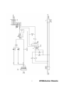
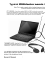
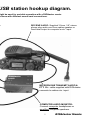
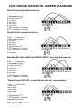
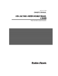
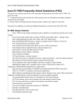
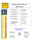
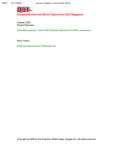
RIGblaster Nomic
rig to sound card interface
USB universal
Owners Manual
7th Edition
RADIO
WEST MOUNTAIN
http://www.westmountainradio.com
1020 Spring City Drive, Waukesha, WI 53186
tel 262.522.6503 fax 262.522.6504
© 2008 West Mountain Radio, All rights reserved.
All trademarks are the property of their respective owners.
Contents of Package
1 -RIGblaster Nomic (COVERS LOOSE FOR EASY SETUP)
1 -Acessory Zip Lock bag:
4 Single pin jumper wires, white with black connectors
4-#6 black stainless steel sheet metal screws
4-double sided adhesive pads
4-stick on protective feet
1 - RIGblaster/RIGtalk CD
1 - 3’ Modular RJ45 to 8 pin round screw on microphone cable
1 - 3’ Modular RJ45 to Modular RJ45 plug in microphone cable
2 - 6’ 1/8” stereo mini plug audio cables
1 - 6’ DB9M to DB9F RS232 serial cable
1 - USB to RS232 serial converter with 6’ cord
1 - Owner’s manual
MISC-Other cables or accessories that you ordered, see your invoice
IF YOU CAN’T FIND IT HERE GO TO OUR SUPPORT PAGE:
http://www.westmountainradio.com/supportno.htm
Owner’s Manual
1
RIGblaster Nomic USB
Owners Manual
Thank you for purchasing a RIGblaster nomic. We hope that it provides many hours of
amateur radio enjoyment.
FOR MAXIMUM ENJOYMENT PLEASE PROCEED IN ORDER, STEP BY STEP! DO
NOT CONTINUE TO THE NEXT STEP UNTIL YOU HAVE CORRECTLY COMPLETED
THE STEP YOU ARE ON.
NOTE: IF YOU CALL FOR SUPPORT WE WILL TO NEED TO KNOW WHAT STEP
OF THIS MANUAL YOU ARE HAVING A PROBLEM WITH. WE MAY NOT BE ABLE
TO HELP YOU IF YOU HAVE NOT READ AND FOLLOWED THE STEP BY STEP
INSTRUCTIONS.
1. INSTALL SOFTWARE AND START RECEIVING: You do not need the RIGblaster
for receive, only for transmit, so leave it in the box. Put our CD in your CD drive and,
after a few seconds, the CD menu should appear on your screen. If the menu does
not appear, you probably need to set your CD ROM drive to autorun (as explained in
Windows help). If you cannot get the CD to autorun, browse to the CDROM and double
click the autorun.exe file in order to display our CD menu.
Please read the CD “read me” file first! We put it there for to read! Note that this product
manual is also on the CD but either the paper or electronic version may be more up to
date with the latest version appearing on our support page.
After reading the Readme file, click the software collection XMIT button; click and select
the PSK31 mode button, and then click the WINPSK program install button. This installs
a simple and easy PSK31 program to get started with. (Only if you are an advanced
user should you install your choice of program or mode.)
Connect your radio’s speaker output to your computer’s line input (mic. on a laptop)
using one of the supplied 1/8” stereo mini plug audio cables. Other connections may be
used but we suggest you test initially with this simple hookup. If you have purchased a
fixed level audio cable from us, made for your model radio, then follow the instructions
that came with that cable for connecting a receive audio signal. Note that you may
use any audio output on your radio (speaker, headphone, record, phone patch, data
audio out) and either of your computer’s inputs, line or mic. inputs. To choose the best
connection, consider the signal levels and your preference for operating convenience.
WARNING: Be certain your computer is powered from the same AC house wiring circuit
(on the same circuit breaker) as the rest of your ham station! This is safer and better
for many reasons that are both related and unrelated to the RIGblaster installation.
Next tune in a signal for the mode and program you have installed and are running.
For PSK31 it is best to tune to 14.07015 USB.
2
RIGblaster Nomic
Open the sound card “Recording Control” panel and select whichever input you are
using, mic. or line, and slide the slider up until see the signals you radio is receiving on
the software’s waterfall display. Note that on most computers you cannot set the input
level to a sound program with the volume control sliders; you must use the recording
control sliders! Set the level as described in the help files and instructions supplied
with the program you are using (We do not write any software so our instructions are
specifically for setting up a RIGblaster. The software instructions should come with
the program.)
After confirming that your software is receiving properly, check that it will generate a
transmit tone. You should be able to hear transmit tones, as sound, coming out of
your computer when the software is placed in its transmit mode. This is an important
test of the computer and software operation. With no transmit sound you will not be
able to transmit!
If you have a problem with this step simply install and try another similar ham radio
program instead. If another program works you can be sure you there was a problem
with the first program. If several programs do not work then double check your sound
card virtual settings and your audio connections.
For more information on using and operating a sound card in a ham station read
K1UHF’s “The In’s and Out’s of a Sound Card” in the October 2003 QST:
http://www.westmountainradio.com/pdf/Ins&Outs.pdf
Continue to the next step only after you have confirmed that you can receive signals
and can hear transmit tones generated.
2. SET THE RIGblaster MICROPHONE WIRING JUMPERS: Different brands of radios
use standard microphone connectors but wire them differently. We have solved this
problem by using jumpers.
You must install jumpers to match your radio’s microphone wiring. The correct jumper
configuration depends on the brand of radio and the type of microphone connector.
Metal eight pin round screw on microphone connector diagrams on page 7 and square
RJ45 modular 8 wire telephone style plugs on page 8. Be certain to use the diagram
that matches both your brand of radio and the type of microphone connector that it uses.
.
If you cannot find the appropriate jumper diagram for your radio check our support page:
http://www.westmountainradio.com/supportno.htm
WARNING: It is possible to damage your radio by shorting out a DC voltage that may
be on your mic. jack. Be certain you have the correct jumper wiring before turning on
your radio.
TIP: The diagrams depict the actual appearance of the jumper block in the RIGblaster.
The black squares with the wires depict where the black and white wire jumpers go. A
circle denotes that no jumper is installed on that pin.
Owner’s Manual
3
After completing the jumper Installation you may put the cover on. Carefully align the
circuit board and covers, making sure that the side screw holes line up. Be careful
not to put force on the potentiometer level control adjustment shaft. The supplied
screws are sheet metal type and must be driven in firmly with a fresh, properly fitting,
#2 Phillips head tip. The screws will be tight at first and then go in easier. Do not over
tighten when they reach bottom.
After you have installed the jumpers and the covers, connect the appropriate RIGblaster
mic. cable, either RJ45 or 8 pin round screw on, between the RIGblaster and your radio.
Proceed to the next step for testing.
3. CONNECT SERIAL CONTROL CABLE: All Amateur Radio sound card programs,
over 100 of them, without exception, require an RS232 serial port for proper operation.
However, most new computers no longer have this connection. Your RIGblaster is
supplied with two cables to provide your choice, and full functionality, with both older
DB9 RS232 serial ports, or with a USB connection. The supplied USB cable will emulate
a DB9 RS32 serial port by converting a USB (universal serial bus) to a RS232 port.
Check to see if your computer has an available DB9 RS232 serial port. If you do, use
the supplied DB9 male to DB9 female cable to connect between the computer’s DB9
RS232 port and the RIGblaster’s DB9 “SERIAL IN” connector. Set the extra USB cable
aside for future use.
If all you have on your computer is a USB socket then use the supplied USB to DB9
converter cable instead.
Refer to centerfold of this manual for a hookup diagram.
If you use the DB9M to DB9F continue to step 5 otherwise if you use the USB cable
continue to the next step.
4. USB CABLE DRIVER INSTALLATION (Skip this step if you are using a actual RS232
serial port on your computer)
The following procedure is to install the software drivers in order to make the USB
cable hardware communicate with your computer. (Mac or Linux drivers are available
on the CD ROM but these instructions are only for Windows 98SE, ME, 2000, XP and
Vista 32 bit.)
A) Insert the West Mountain Radio CD ROM in your computer’s CDROM drive.
B) Plug the USB connector into an available USB socket on your computer. If possible
one you will keep it in.
C) A “New hardware found” Windows Plug & Play Wizard window should pop up.
D) For XP and Vista you should allow Windows to automatically complete the installation.
E) For Windows 98SE, ME and 2000 “tell” Windows to go to a specific location and
direct Windows ONLY to the CDROM drive letter that has the West Mountain CD in it.
F) At each prompt select whatever response that will cause Windows to complete the
hardware installation. (DO NOT cancel, go back, stop, or abort the installation! NO
MATTER WHAT!)
4
RIGblaster Nomic
G) You have completed the USB hardware driver installation at this point.
H) Plug the DB9 end connector into the RIGblaster’s “Serial in” jack and screw in the
thumb screws.
I) Right click the “My Computer” icon and then left click “Properties”.
J) Select the “Hardware” tab and then select “Device Manager”.
K) Scroll down and click the + symbol next to “Ports (COM & LPT)”
L) Check that you see the item: “Prolific USB-to-Serial Comm Port (COMx)”
M) **IMPORTANT** Make a note of what the COM number is, (x in (COMx). You will
need that number to setup your Amateur Radio program to do PTT.
If this step is OK, it confirms that your USB to serial converter is properly installed and
should work. If and only if this is confirmed correctly, continue to the next step.
5. SERIAL PTT CONTROL SET UP AND TEST: Run the program that you had working
in step 1. From that program’s configuration or setup menu, (consult the program’s
help docs) set the program to control PTT using the COM port that your RIGblaster’s
serial cable is plugged into. The RIGblaster nomic responds to both RTS and DTR for
PTT control; use either or both, if you have a choice.
Put that software into transmit (TX) and check that your radio automatically switches
to transmit and shows PTT activation (It may be normal not to see any RF output until
you complete the next step).
Continue to the next step only if you have computer PTT control working properly.
6. CONNECT THE TRANSMIT AUDIO: Connect one of the supplied 1/8” stereo audio
cables from your sound card’s line output (laptop headphone output) to the RIGblaster’s
audio in. If you unplug your desktop computer’s speakers to make this connection
then plug the computer speakers back in to the RIGblaster’s audio output so they will
operate as they did before. If you wish, instead, you can use computer headphones
connected from the RIGblaster’s audio output to hear the computer. WARNING: if you
connect un-amplified speakers or low impedance headphones, not intended for use
with a computer, you may not have enough transmit audio to transmit.
7. SET THE TRANSMIT AUDIO LEVEL TO YOUR RIG: Use your normal mic. gain
setting, turn your speech compressor off, and set the transmitter’s RF drive (power
control) all the way up (full power). You will be able to set your power level to any
power level later with the computer audio drive setting. WARNING: Failure to set your
RF power/drive to maximum may cause severe transmitter distortion and a wide signal.
Confirm that the RIGblaster’s audio level control is turned all the way up, full clockwise
(DO NOT USE FORCE! you could damage the control).
Owner’s Manual
5
6
RIGblaster Nomic
Typical RIGblaster nomic U
Note: This is only a sample station hookup diagram; what m
A desktop computer would have similar conne
PTT CONTROL: Use either supplied DB9M to DB9F serial cable connected
between the RIGblaster’s serial port and the computer’s RS232 serial port. If the
computer doesn’t have a DB9 (9 pin) serial port, use the supplied USB to DB9
serial converter. (The USB converter cable requires a driver installation)
TRANSMIT AUDIO: Supplied 3.5 mm, 1/8”
stereo phone plugaudio cord from computer’s
headphone* output to RIGblaster’s audio in.
* For desktop computers use the computer’s line
input in place of the mic. input and use the line output
in place of the headphone output.
Owner’s Manual
7
USB station hookup diagram.
might be used for portable operation with a RIGblaster nomic.
ections with different sound card connections.
e
Receive AUDIO: Supplied 3.5mm, 1/8” stereo
phone plug audio cord from radios speaker or
fixed level output to computer’s mic* input.
MICROPHONE TRANSMIT AUDIO &
PTT: Mic. cable supplied with RIGblaster
connects to radios mic. input.
COMPUTER AUDIO MONITOR:
Connect computer headphones or
amplified computer speakers.
8
RIGblaster Nomic
Open your Windows sound card playback “Volume control” panel (double click the little
speaker icon in the system tray). Un-mute or select the “wave” output and the left hand
“Volume Control” output. Set the virtual “Volume” and “Wave” sliders about one notch
down from the top. Set the virtual balance sliders to the center.
If you have computer speakers hooked up and they have a volume control knob, turn
that knob most of the way, but not all of the way, down. If your computer speakers do
not have a volume knob they may be too loud when your sound card is properly set to
transmit with your radio. You may have to disconnect them or turn them off.Set your
software to transmit. Your radio should indicate PTT activation and your computer audio
should be going to your rig and you should be transmitting at full power. The audio
level will probably be much too high. Turn down the wave output, master volume and
RIGblaster audio level as necessary. You must achieve something less than full RF
output using your normal mic. setting, with the RF drive (power output) set to maximum.
With an FM rig you must set the audio level using a deviation meter or by comparing the
level of your transmit audio to other stations by using a second receiver. For EchoLink®
system operation use the 9999 test server.
The sound card sliders should end up between 1/4 and 3/4 of the way up and the
RIGblaster audio level control set between 1/8 and 7/8 of the way up. You should be able
to achieve a happy balance between controls when they are all set properly. Remember
that there are multiple audio controls cascaded and all interact. If any one of the controls
is turned down too much it will give the appearance of NO TRANSMIT SIGNAL, NO RF
OUTPUT. Little or no RF output is usually caused by setting the sound card too low,
setting the RF power less than max or the wrong speakers or headphones plugged in.
HINT: If you didn’t configure your software to control PTT as was explained in steps 4,
5 and 6 you will not be able to transmit. Nothing will happen unless you set up your
radio for VOX operation or you manually activate PTT with a MOX switch.
HINT: if you are using PSK software, make sure that the transmit audio frequency is
between 500 Hz and 2500 Hz otherwise you may be outside the limits of your radio’s
audio pass band and you may not be able to transmit.
HINT: While the software is in transmit check for the presence of transmit tones by
listening at the RIGblaster’s audio output jack with either headphones or computer
speakers. Do not use low impedance un-amplified speakers or headphones, they will
effectively short out your sound card output.
8. WORK LOTS OF DX AND HAVE FUN: You are on the air! Try all the modes, not
just one; experiment!
This completes the basic instructions of this manual. For more information please read
further, or visit our RIGblaster nomic support page.
http://www.westmountainradio.com/supportno.htm
Owner’s Manual
9
NOTES ON SETTING THE AUDIO LEVEL TO YOUR RIG:
Before using the RIGblaster you should set your radio properly for normal SSB operation.
Changing your microphone settings on your rig after setting up the RIGblaster will require
that you re-adjust the RIGblaster or computer.
To have the best possible signal, you need to understand how your rig is adjusted.
Modern rigs may have several adjustments for transmit audio, including; mic. gain,
mic. equalization and/or transmit shift, speech compression and ALC (automatic level
control). The objective of setting these adjustments is to have clean clear signal and
minimum splatter or RF bandwidth.
The primary adjustment is mic. gain which sets the amount of audio amplification for
the microphone. A speech compressor basically makes loud speech softer and soft
speech louder, reducing the range between soft and loud. If your rig has transmit shift
or audio equalization you can adjust the tone quality of your microphone audio. An
ALC circuit is provided to minimize the possibility of too much audio over driving the rig,
causing flattopping or splatter. You should understand the interaction of these circuits,
and their adjustments. Consider your microphone and personal voice characteristics.
To get the best audio from your station and work the most DX you need to set your
radio carefully. Turning everything up for maximum smoke will NOT make you more
intelligible....you will only be distorted.
The main idea of adjusting your rig is to not overdrive it. If you set your RF drive on
the radio to full power and you adjust your computer audio drive to less than full power
you should ALWAYS have a clean signal whether your using your mic. or the computer.
Always check that the audio level is BELOW the ALC activation or protection point.
It you adjust your transmit shift and/or transmit audio equalization (tone controls) for
the best on-the-air reports with your mic. you may need to center them for computer
sound card operation
Speech compression is not used with most sound card software, but there are exceptions
with pure FSK operation. Usually you should turn of your speech compressor before
using the RIGblaster.
Be sure that your radio is set up properly for voice operation at full power before you
set the audio drive level from your computer to your rig with the RIGblaster. Do not
change your basic mic. settings.
For most modes of operation with a sound card turn off your rig’s speech compressor.
Confirm that your RF drive/transmit power control set to maximum. Double click the
little speaker icon in your computer’s system tray. Adjust the master volume control
(the one on the left) and the wave volume as high as needed to drive your rig properly;
generally between 1/4 and 3/4 of the way up. The RIGblaster’s “audio level” control
is used to match the computer audio level to the radio, a one time setting. Set all of
these controls so that none of them are near all of the way up or down. Remember that
all of the adjustments are all cascaded (in series), and they all interact.
10
RIGblaster Nomic
Your final setting should produce approximately 50% RF power output from your radio.
Warning: you should not exceed the AM, FM or RTTY power ratings of your radio. After
all settings are completed, check to make sure your ALC meter is below activation and
that your are putting out less than full power with the radio’s drive/power setting at max.
NOTE: if you run your sound card turned all the way up and compensate by turning
the RIGblaster far down, you may distort the sound card output and have poor quality
signal. A similar thing will happen if you set your radio to very low power and try to turn
up the RIGblaster and computer too high to compensate.
VOX OPERATION
To use the VOX in your radio to transmit with the RIGblaster set everything as outlined
previously in this manual. If you do not have a serial port connected for automatic PTT
control use your MOX button to activate transmit during level setting. Connect your
mic. and turn rig’s VOX on and set the VOX level, delay and anti-trip controls so that
they work well with your mic. Connect the RIGblaster. The same settings should work
with the computer as the computer audio should be matched, almost exactly in level,
as your voice from your mic.
SWITCHES, CONNECTIONS, INDICATORS AND FEET
The serial in jack connects the RIGblaster nomic to the computer’s serial port for
automatic PTT activation. It responds to a steady high state of either the RTS or DTR
line of the computer’s serial port. If software or firmware of the computer sets either of
those lines high any PTT control interface will be stuck in transmit.
The audio in accepts a standard 1/8” stereo mini plugs. It is a stereo connection from
the computer, both channels are summed together and that feeds the transmit audio
signal in to the RIGblaster.
The audio level adjustment potentiometer gives a great range of adjustment to match
the nominal output of the computer to your radios mic. jack. Clockwise is maximum.
The audio out jack is wired in stereo and in parallel with the audio in jack. It is intended
to monitor the audio from the computer with computer speakers or headphones.
The mic. out connects the RIGblaster to a radio using an appropriate West Mountain
Radio mic. cable that matches the mic. jack of the radio. The wiring is set, or adapted,
to match the radio with the installation of jumpers inside the RIGblaster. This cables
carries both the microphone transmit audio signal and it connects the radios PTT circuit.
We have included your choice of protective feet and stick on pads in the package.
TROUBLESHOOTING
If you have installed the RIGblaster following the steps in this manual you need not go
back to a previous step. The problem is isolated to the step that you found the problem
on. Please be sure you know which step of this manual you are stuck on before contacting
us for support, it will be a big help.
Most common problems are software related and are fixed with a mouse but require
reading the software documentation or help files.
Owner’s Manual
11
TYPICAL PROBLEMS:
1)The software has no receive signal displayed because the sound card input is not
turned on or up. Use the Windows® sound card “Recording Control” panel not the
playback “Volume Control” panel, duplex sound cards cannot be adjusted for receive
from the Windows® playback “Volume Control” panel.
2) The ham radio software is not set to the correct serial port for PTT control. All programs
must be configured to control PTT, they will not work unless you do this.
3) The sound card wave and volume outputs are set too low because the computer
speakers are too loud. Turn down or turn off your computer speakers and turn your
sound card up.
4) The RF power / Drive control on the radio is not set to maximum causing the computer
not to have enough audio to drive the radio even to half output.
5) Low impedance headphones or speakers are loading down the RIGblaster’s audio
output from the sound card. Disconnect them or replace them with computer headphones
or speakers.
6) The computer is “stuck in transmit” (RTS and/or DTR is high). This is a computer
problem common with Dell® Windows® XP® computers, you would have the same
problem no matter what brand of interface you are using. A work around for this is to
load a ham radio program, hit transmit and then go back to receive. This should fix the
problem temporarily so that you may operate. The permanent fix is to get the computer
manufacturer to support and fix their hardware.
If the computer is running an early version of Windows® Me® you will have the same
problem. Go to our support page and use the link for the official Microsoft® Windows®
ME upgrade .
If you would like further help, see our support page, for the latest help and suggestions:
http://www.westmountainradio.com/supportno.htm
Please understand that the RIGblaster will not work if the software and computer do not
work. Make sure that you have your software operating properly BEFORE connecting
the RIGblaster and expecting it to work. You must read the documentation that comes
with the software! Software instructions are not included in this manual. We did not write
the software and we cannot properly support the software. The best thing to do if you
have software problems is to try a different software package. If you have problems
with two or more sound card programs you probably have a problem with your Windows
sound card software installation, not your sound card hardware.
Enjoy operating and work lots of DX!
The hams at West Mountain Radio
12
RIGblaster Nomic
8 PIN ROUND SCREW ON JUMPER DIAGRAMS
Alinco® 8 pin round screw on
Pin #
Connection
1 Microphone audio
2 Push to talk, PTT
3 not used
4 not used
5 not used
6 not used
7 Mic. common (Ground)
8 PTT common (Ground)
Icom® 8 pin round screw on
Pin #
Connection
1 Microphone audio
2 not used
3 not used
4 not used
5 Push to talk, PTT
6 PTT common (Ground)
7 Mic. common (Ground)
8 not used
Kenwood®, Elecraft® and SGC® 2020 8 pin round screw on
Pin #
Connection
1 Microphone audio
2 Push to talk, PTT
3 not used
4 not used
5 not used
6 not used
7 Mic. common (Ground)
8 PTT common (Ground)
Yaesu® and JRC 8® round pin screw mic. connectors.
Pin #
Connection
1 not used
2 not used
3 not used
4 not used
5 not used
6 Push to talk, PTT
7 PTT and Mic. common
8 Microphone audio
Owner’s Manual
13
RJ45 MODULAR PLUG-IN TELEPHONE STYLE
JUMPER DIAGRAMS
Kenwood® RJ45 (8 wire) Modular mic. connector radios
Pin #
Connection
1 not used
2 not used
3 PTT common (Ground)
4 Push to talk, PTT
5 MIC. common (Ground)
6 Microphone audio
7 not used
8 not used
Typical Yaesu® RJ45 (8 wire) Modular mic. connector radios
Most but not all FM rigs. including FT817,FT897,FT857
Pin #
Connection
1 not used
2 PTT common (Ground)
3 Push to talk, PTT
4 Microphone audio
5 MIC. common (Ground)
6 not used
7 not used
8 not used
Icom® RJ45 (8 wire) Modular mic. connector radios
IC706 (all versions), and Icom FM radios
Pin #
Connection
1 not used
2 PTT common (Ground)
3 Microphone audio
4 MIC common (Ground)
5 Push to talk, PTT
6 not used
7 not used
8 not used
Radio Shack® RJ45 (8 wire) Modular mic. connector radios
HTX242 etc., FM radios
Pin #
Connection
1 not used
2 not used
3 Push to talk, PTT
4 Microphone audio
5 not used
6 not used
7 PTT common (Ground)
8 not used
14
RIGblaster Nomic
RIGblaster
Warranty
The RIGblaster is warranted against failure due to defects in workmanship
or materials for one year after the date of purchase from West Mountain
Radio. Warranty does not cover damage caused by abuse, accident,
misuse, improper or abnormal usage, failure to follow instructions, improper
installation, alteration, lightning, or other incidence of excessive voltage or
current. If failure occurs within this period, return the RIGblaster or accessory
to West Mountain Radio at your shipping expense. The device or accessory
will be repaired or replaced, at our option, without charge, and returned to
you at our shipping expense. Repaired or replaced items are warranted for
the remainder of the original warranty period. You will be charged for repair
or replacement of the RIGblaster or accessory made after the expiration
of the warranty period.
The Compact Disc of Radio Amateur Software Collection is excluded from
any and all warranties by West Mountain Radio. Note that the programs
have been provided as shareware or freeware by the software authors to
the amateur radio community for their use and enjoyment. The CD is to be
used at your own risk.
West Mountain Radio shall have no liability or responsibility to customer
or any other person or entity with respect to any liability, loss, or damage
caused directly or indirectly by use or performance of the products or arising
out of any breach of this warranty, including, but not limited to, any damages
resulting from inconvenience, loss of time, data, property, revenue, or profit,
or any indirect, special incidental, or consequential damages, even if West
Mountain Radio has been advised of such damages.
Except as provided herein, West Mountain Radio makes no express
warranties and any implied warranties, including fitness for a particular
purpose, are limited in duration to the stated duration provided herein.
www.westmountainradio.com
1020 Spring City Drive, Waukesha, WI 53186
tel 262-522-6503 fax 262-522-6504