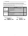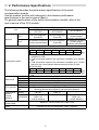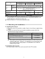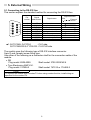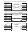
1
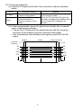
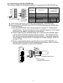
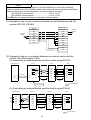
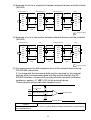
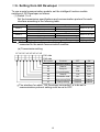
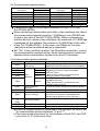
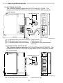
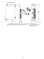
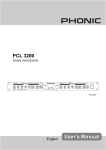
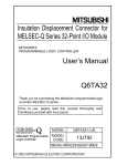
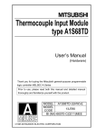
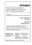
Serial Communication Module User's Manual (Hardware) QJ71C24N, QJ71C24N-R2 QJ71C24N-R4 QJ71C24, QJ71C24-R2 Thank you for purchasing the Mitsubishi programmable logic controller MELSEC-Q Series. Prior to use, please read both this manual and detailed manual thoroughly to fully understand the product. MODEL QJ71C24-U-HW-JE MODEL 13JQ31 CODE IB(NA)-0800008-D(0212)MEE 1999 MITSUBISHI ELECTRIC CORPORATION • SAFETY PRECAUTIONS • (Be sure to read these instructions before using the product.) Before using this product, read this manual and the relevant manuals introduced in this manual carefully and handle the product correctly with full attention to safety. Note that these precautions apply only to this product. Refer to the user's manual of the CPU module for the PLC system safety precautions. In this manual, the safety instructions are ranked as "DANGER" and "CAUTION". DANGER CAUTION Indicates that incorrect handling may cause hazardous conditions, resulting in death or severe injury. Indicates that incorrect handling may cause hazardous conditions, resulting in minor or moderate injury or property damage. CAUTION level instructions may also lead Note that failure to observe the to serious results depending on the circumstances. Be sure to observe the instructions of both levels to ensure personal safety. Please keep this manual in accessible place and be sure to forward it to the end user. A-1 [DESIGN PRECAUTIONS] CAUTION z Do not bundle the control lines or communication cables with the main circuit or power lines, or bring them close to each other. The distance of 100mm(3.9inch) or more should be ensured. Failure to do so cause malfunctions due to noise. [INSTALLATION PRECAUTIONS] CAUTION z Use the PLC in the environment specified in the user's manual of the CPU module. Failure to do so may cause electric shock, fires, malfunctions, product deterioration or damage. z When mounting the module, fully insert the module fixing projection into the corresponding fixing hole on the base unit while pressing the module fixing lever at the bottom of the module. Incorrect mounting may cause malfunctions, failures or a fall of the module. The module should be secured with screws in an environment of frequent vibration. z Tighten the screws within the specified torque range. Loose tightening may cause a fall, short circuits, or malfunctions. Overtightening may damage the screws and/or the module, resulting in a fall of the module, short circuits or malfunctions. z Be sure to shut off all phases of the external power supply before mounting or removing the module. Failure to do so may damage the module. z Do not directly touch the conductive part or electronic components of the module. This may cause malfunctions or a failure of the module. A-2 [WIRING PRECAUTIONS] CAUTION z When energizing and operating the product after mounting and wiring, be sure to cover the terminals with the provided terminal covers. Failure to do so may result in malfunctions. z When wiring the external connection connectors, correctly press, pressureweld or solder the connecting part by using the tool specified by the manufacturer. Poor connection may cause short circuits, fires or malfunctions. z Connect the connectors to the module securely. z Be sure to fix communication cables and power cables to the module by ducts or clamps. Failure to do so may cause damage of the module or the cables due to accidental pull or unintentional shifting of the cables, or malfunctions due to poor contact of the cable. z When connecting a cable, check the interface type and connect it correctly. Connecting to a wrong interface or faulty wiring may cause failure of the module and/or external devices. z Tighten the terminal screws within the specified torque range. Loose tightening may result in a fall, short circuits or malfunctions. Overtightening may cause damage to the screw and/or the module, resulting in a fall, short circuits or malfunctions. z Do not hold the communication cable by hand when pulling it out from the module. Be sure to hold the connector by hand, when removing the cable with a connector from the module. Failure to do so may cause malfunctions or damage to the module or cable. z Be careful not to let foreign matter such as dust or wire chips get inside the module. This may cause a fire, failure or malfunctions. z A protection label is attached to cover the upper part of a module to prevent the entry of foreign matter. Do not remove the label during wiring. However, be sure to remove it for heat dissipation during system operation. A-3 Revisions The manual number is given on the bottom left of the back cover. Print Date Manual Number Revision Sep., 1999 IB(NA)-0800008-A First printing Dec., 1999 IB(NA)-0800008-B Addition "Compliance with the EMC Directive and Low Voltage Directive", Chapter 6 (1) (a) · (c) ·(2) REMARK Correction "Safety Precautions", Chapter 2, Section 5.2 (3) Sep., 2000 IB(NA)-0800008-C Add the contents of the function version B. Put Windows base software products together from Mitsubishi Programmable Logic Controller MELSEC series to Mitsubishi integrated FA software MELSOFT series. Standardize the name from software package (GPP function) to product name (GX Developer). Correction "Safety Precautions", "Manuals", "Compliance with the EMC Directive and Low Voltage Directive", Chapter 2, Chapter 6(1)(b)(c). Dec., 2002 IB(NA)-0800008-D Addition model QJ71C24N, QJ71C24N-R2, QJ71C24N-R4 This manual confers no industrial property rights or any rights of any other kind, nor does it confer any patent licenses. Mitsubishi Electric Corporation cannot be held responsible for any problems involving industrial property rights which may occur as a result of using the contents noted in this manual. 1999 MITSUBISHI ELECTRIC CORPORATION A-4 CONTENTS 1. Overview...................................................................................................... 1 2. Performance Specifications ......................................................................... 2 3. Mounting and Installation ............................................................................. 3 3.1 Handling Precautions ............................................................................. 3 3.2 Installation Environment ......................................................................... 3 4. Part Names.................................................................................................. 4 5. External Wiring ............................................................................................ 6 5.1 Connecting to the RS-232 line................................................................ 6 5.2 Connecting to the RS-422/485 line ......................................................... 9 6. Setting from GX Developer ........................................................................ 13 7. External Dimensions .................................................................................. 16 Manuals The following table lists manuals relevant to this product. If necessary, obtain a proper manual in accordance with the intended use. Relevant Manuals Manual name Q Corresponding Serial Communication Module User's Manual (Basic) Q Corresponding Serial Communication Module User's Manual (Application) Q Corresponding MELSEC Communication Protocol Reference Manual Manual No. (Model code) SH-080006 (13JL86) SH-080007 (13JL87) SH-080008 (13JF89) Please read the Q Corresponding Serial Communication Module User's Manual (Basic) before using this module. Compliance with the EMC Directive and the Low Voltage Directive When incorporating Mitsubishi PLC into other machine or equipment and making it comply with the EMC directive and the low voltage directive, refer to Chapter 3, "EMC Directive and Low Voltage Directive" of the User's Manual (Hardware) for the CPU module. The CE logo is printed on the rating plate of the PLC, indicating compliance with the EMC directive and the low voltage directive. No measured for compliance with the EMC Directive and the low voltage directive are required for this product. A-5 1. Overview This manual is written to provide proper information and instructions on installation and wiring of the QJ71C24N, QJ71C24N-R2, QJ71C24N-R4, QJ71C24 and QJ71C24-R2 serial communication modules (hereinafter referred to as the serial communication module). Check that the following items are included with the product package. Model name QJ71C24N or QJ71C24 QJ71C24N-R2 or QJ71C24-R2 QJ71C24N-R4 Product name QJ71C24N or QJ71C24 serial communication module Terminal resistor for RS-422 communication 330 1/4 W (Orange-Orange-Brown) *1 Terminal resistor for RS-485 communication 110 1/2 W (Brown-Brown-Brown) *1 QJ71C24N-R2 or QJ71C24-R2 serial communication module QJ71C24N-R4 serial communication module Terminal resistor for RS-422 communication 330 1/4 W (Orange-Orange-Brown) *1 Terminal resistor for RS-485 communication 110 1/2 W (Brown-Brown-Brown) *1 Plate terminal for braided shield cable connection 1: Differentiate the terminal resistors as follows: 330 110 Orange Orange Brown 1 Brown Brown Brown Quantity 1 2 2 1 1 4 4 4 2. Performance Specifications The following describes the performance specifications of the serial communication module. Use the modem function with reference to the relevant performance specifications in the user's manual (Basic). For general specifications of the serial communication module, refer to the user's manual of the CPU module. Specifications (when the modern function is not used) Item QJ71C24N QJ71C24N-R2 QJ71C24N-R4 QJ71C24 QJ71C24-R2 RS-422/485-compliance RS-232-compliance RS-232-compliance CH.1 (2-piece plug-in (D-sub 9P) (D-sub 9P) connector socket block) Interface RS-422/485-compliance RS-422/485-compliance RS-232-compliance CH.2 (2-piece plug-in (2-piece terminal block) (D-sub 9P) connector socket block) Synchronization method Start-stop synchronization method [QJ71C24N(-R2/R4)] 50 300 600 1200 2400 4800 9600 14400 19200 28800 38400 57600 115200 230400 (bps) • Transmission speed 230400 bps is available for only CH1. (Not available for CH2) • Total transmission speed of two interfaces is available up to 230400 bps. Transmission speed • Total transmission speed of two interfaces is available up to 115200 bps when the communication data monitoring function is used. [QJ71C24(-R2)] 50 300 600 1200 2400 4800 9600 14400 19200 28800 38400 57600 115200 (bps) • Total transmission speed of two interfaces is available up to 115200 bps. Start bit 1 Data bit 7/8 Data format Parity bit 1(vertical parity) or none Stop bit 1/2 Parity check For all protocol, select odd/even by the parameter when there is an error. Error detection Sum check Select by the parameter for MC protocol/Bidirectional protocol. code Select by the user entry frame for non-procedure protocol. Maximum 15 m Maximum 15 m Transmission RS-232 (49.2 ft.) (49.2 ft.) distance Maximum 1200 m Maximum 1200 m (Overall RS-422/485 (4592.4 ft.) (4592.4 ft.) distance) (overall distance) (overall distance) Allowable number of writes Maximum 100,000 writes to the same area to flash ROM Number of occupied I/O 32 points per slot (I/O assignment: Intelli: 32 points) points 2 Specifications (when the modern function is not used) QJ71C24N QJ71C24N-R2 QJ71C24N-R4 QJ71C24 QJ71C24-R2 7/0. 127 P HRV-SV Outside diameter 8.5mm (0.33in.) or more RS-232 (Oki Electric Cable Co., Ltd. Applicable number is specified in .) Recommended SPEV (SB)-MPC-0.2×3P Outside diameter approx. 6.5mm (0.26 in.) cable RS-422/485 (Mitsubishi Cable Industries, LTD.) (*1) SPEV(SB)-0.2×3P Outside diameter approx. 7.5mm (0.3 in.) (Mitsubishi Cable Industries, LTD.) Applicable connector for 9 pin D-sub (male) screw type (*2) external wiring 5V DC internal current 0.31A 0.26A 0.39A consumption External dimensions 98 (3.86 in.) (H) 27.4 (1.08 in.) (W) 90 (3.54 in.) (D)[mm] Weight 0.20kg (0.44lb) Item 1: Recommended cables SPEV (SB)-MPC-0.2 × 3P and SPEV (SB)-0.2 × 3P are equivalent in the electrical characteristics, but partially different in the outside diameter, internal wire colors, etc. 2: Refer to Section 5.1 for the recommended cable. 3. Mounting and Installation 3.1 Handling Precautions (1) Since the case of the module is made of resin, do not drop or apply strong impact. (2) Tighten the terminal block and module installation screws within the specified torque range as follows: Screw location RS-422/485 terminal block terminal screws (M3 screw) RS-422/485 plug-in connector socket block terminal screw for QJ71C24N-R4 (M2 screw) Module fixing screw (normally not required) (M3 screw) ( 1) Tightening torque range 42 to 58N•cm 20 to 25N•cm 36 to 48N•cm 1: The module can be simply fixed onto the base unit with a hook on the module's upper part. However, for installation in an environment with high vibration and/or strong impact, it is advisable to fix it with the module fixing screws. 3.2 Installation Environment For further details, refer to the user's manual for the CPU module. 3 4. Part Names QJ71C24N QJ71C24 ( 1) QJ71C24N-R2 QJ71C24-R2 ( 2) QJ71C24N 1) CH1 RUN NEU. SD RD QJ71C24N-R4 QJ71C24N-R2 ERR. NEU. SD CH2 RD 1) CH1 RUN NEU. SD RD ERR. NEU. SD CH2 RD QJ71C24N-R4 1) CH1 RUN NEU. SD RD ERR. NEU. SD CH2 RD CH1 RS-422/485 2) SDA CH1 RS-232 SDB 2) CH1 RS-232 4) RDA RDB SG (FG) CH2 RS-422/485 SDA SDB 3) 3 4 2) RDA CH2 RS-232 RDB SG 5 (FG) RDB SDB 4) 2 (FG) RDA SDA 1 SG (FG) 6 CH2 RS-422 /485 7 QJ71C24N-R2 QJ71C24N-R4 *1: The dimensions of the QJ71C24 are the same as QJ71C24N (except for model name). *2: The dimensions of the QJ71C24-R2 are the same as QJ71C24N-R2 (except for model name). 1) Name Display LED 2) RS-232 Interface 3) 4) RS-422/485 Interface RS-422/485 Interface Contents Display LED (For details, see Section (1).) RS232 interface for serial communication with external devices (D-Sub 9P) RS422/485 interface for serial communication with external devices (2-piece terminal block) RS422/485 interface for serial communication with external devices (2-piece plug-in socket block) 4 (1) LED display list QJ71C24N CH1 CH - LED RUN NEU. SD RD QJ71C24N-R2 ERR. NEU. SD CH2 RD Display contents Normal RUN operation display Error display ERR (*1) CH1 ON/Flickering Normal QJ71C24N-R4 ERR. NEU. SD CH2 RD OFF CH1 RUN NEU. SD RD ERR. NEU. SD CH2 RD Compatible protocol NonMC Bidirectional procedural Faulty or reset Valid Error has occurred Waiting for MC Neutral status NEU command on the CH1 side (*3) message to be display (*2) received CH1 Transmission Data being SD status display transmitted Reception Data being RD status display received Waiting for MC Neutral status NEU command on the CH2 side (*3) message to be display (*2) received CH2 RUN NEU. SD RD SD Transmission status display Data being transmitted RD Reception status display Data being received Normal MC command message being received Valid Data not transmitted Data not received MC command message being received MC command message not transmitted MC command message not received Invalid (OFF) Valid Valid Invalid (OFF) Valid 1: This LED turns ON when an error occurs at serial communication module hardware or during data communication. 2: This LED displays the data communication status via MC protocol. On: Waiting for the command message to be received from the external device. Off: Processing the command message received from the external device. 3: This LED can be made valid also when "GX Developer connection" (0H) is specified in communication protocol setting. 5 5. External Wiring 5.1 Connecting to the RS-232 line This section explans the standard method for connecting the RS-232 line. 1 2 3 4 5 6 7 8 9 Pin number Signal abbreviation 1 2 3 4 5 6 7 8 9 CD RD(RXD) SD(TXD) DTR(ER) SG DSR(DR) RS(RTS) CS(CTS) RI(CI) Signal name Signal direction C24 External ( 1) device Receive carrier Reception data Transmission Data terminal ready Signal ground Data set ready Transmission request Transmission possible Called status display 1: QJ71C24N, QJ71C24 : CH1 side, QJ71C24N-R2 QJ71C24-R2 : CH1/CH2 side The module uses the following type of RS-232 interface connector. 9-pin D-sub (female) screw fixing type Use either of the following as a connector shell for the connection cable of the module. • 3M Plug model: 8209-6009 Shell model: 3702-2209 M2.6 • Tyco Electronics AMP K.K. Plug model: 747904-2 Shell model: 747515 or 174469-2 POINT To connect the module with a modem/TA when using modem function, install wiring as specified for the modem/TA. 6 (1) Example of connection to an external device which can turn on/off the CD signal (pin No. 1) The module Signal Pin number name CD 1 RD(RXD) 2 SD(TXD) 3 DTR(ER) 4 SG 5 DSR(DR) 6 RS(RTS) 7 CS(CTS) 8 RI(CI) 9 Cable connection and signal direction (Connection example of full or half duplex communication) External device Signal name CD RD(RXD) SD(TXD) DTR(ER) SG DSR(DR) RS(RTS) CS(CTS) (2) Example of connection to an external device which cannot turn on/off the CD signal (pin No. 1) (a) Example of connection for DC code control or DTR/DSR control The module Signal Pin number name CD 1 RD(RXD) 2 SD(TXD) 3 DTR(ER) 4 SG 5 DSR(DR) 6 RS(RTS) 7 CS(CTS) 8 RI(CI) 9 Cable connection and signal direction (Connection example of full duplex communication) External device Signal name CD RD(RXD) SD(TXD) DTR(ER) SG DSR(DR) RS(RTS) CS(CTS) (b) Example of connection for DC code control The module Signal Pin number name CD 1 RD(RXD) 2 SD(TXD) 3 DTR(ER) 4 SG 5 DSR(DR) 6 RS(RTS) 7 CS(CTS) 8 RI(CI) 9 Cable connection and signal direction (Connection example of full duplex communication) External device Signal name CD RD(RXD) SD(TXD) DTR(ER) SG DSR(DR) RS(RTS) CS(CTS) 7 (3) Connection precaution (a) Treat the FG signal and shield of the connection cable as indicated below: FG signal Shield Connection method Connect to the connector enclosure of the module. Connect to the FG terminal of the external device or connector enclosure of the module. Remark • Do not short the FG signal and SG signal of the connector cable. • When the FG signal and SG signal are internally connected in the external device, do not connect the FG signal to the module. (b) If data communication cannot be performed normally due to external noise, install wiring as follows: • Connect the FG terminal of the external device and the connector enclosure of the module using the connector cable shield. • Use a twisted pair style between each signal (except SG) and SG signal. Shield Module Connector enclosure (External device) FG SD RD RD SD DSR DTR DTR DSR SG SG 8 5.2 Connecting to the RS-422/485 line This section explains the standard method for connecting the RS-422/485 line. SDA SDA SDB SG RDA RDB Signal abbreviation Signal name SD SDB RDA RDB SG FG FG Transmission data (+) Transmission data (-) Reception data (+) Reception data (-) Signal ground Frame ground Frame ground SDB (FG) RDA SG (FG) RDB (FG) QJ71C24N-R4 ( 2) QJ71C24N QJ71C24 Signal direction External C24 ( 1) device 1 QJ71C24N, QJ71C24 : CH2 side, QJ71C24N-R4 : CH1/CH2 side 2 Connect the RS-422/485 line of QJ71C24N-R4 while paying full attention to the followings: 1) Use the RS-422/485 cable recommended in chapter 2. Performance specifications. Be sure to strip the outer insulation layer by 7mm before connecting the cable to the plug-in socket block. 2) When connecting the braided shield wire inside the RS-422/485 cable, use the plate terminals included with the product. The braided shield wire can be connected without the plate terminal. Four plate terminals are included to connect the FG terminals of the both stations. (Refer to section 5.2.(6) 3) When connecting the plug-in socket block to the QJ71C24N-R4, be sure to confirm the layout of the socket block and then insert it into the RS-422/485 connector on the QJ71C24N-R4. QJ71C24N-R4 CH1 RUN NEU. SD RD 7m m (0.2 8 in .) ERR. NEU. CH2 SD RD SDA CH1 RS-422/485 SDB SDA SDB RDA RDA RDB RDB SG SG (FG) CH2 RS-422/485 (FG) Braided shield wire SDA SDB RDA RDB Plate terminal (included with product) SG (FG) QJ71C24N-R4 9 POINT If the module is the first or last station on the RS-422/485 line, connect the following terminal resistor to the RS-422/485 interface with reference to the examples shown below. Data communication will be disturbed if a terminal resistor is not used. • For RS-422 communication .............................. 330 Ω 1/4 W • For RS-485 communication .............................. 110 Ω 1/2 W The R in the examples shown below indicates a terminal resistor. (1) Example of one-to-one connection between an external device and the module (RS-422, RS-485) External device Signal name Module Signal name Terminal resistor R SDA RDA SDB RDB RDA SDA RDB SDB SG RSA FG RSB FG CSA Terminal resistor R CSB SG FG (2) Example of one-to-n connection between an external device and the module (RS-485 between C24s) (a) Connecting an external device and the module using RS-232 C24 1) External device SDA SDA SDA SDB SDB SDB RDA RDA RDA RDB RDB RDB SD SG SG SG RD FG R R RS-232 SD RD C24n C24 2) FG RS-422/485 cable R R FG RS-422/485 cable Terminal resistor R Link operation (b) Connecting an external device and the module using RS-485 External device R R C24n C24 1) C24 2) SDA SDA SDA SDA SDB SDB SDB SDB RDA RDA RDA RDA RDB RDB RDB RDB SG SG SG SG FG FG RS-422/485 cable RS-422/485 cable R 10 R FG FG RS-422/485 cable R Terminal resistor (3) Example of one-to-n connection between external devices and the module (RS-485) C24 1) External device 1) External device 2) SDA SDA SDA SDA SDB SDB SDB SDB RDA RDA RDA RDB RDB RDB RDB SG SG SG SG R FG External device n FG R FG FG RS-422/485 cable RS-422/485 cable RDA RS-422/485 cable Terminal registor R (4) Example of m-to-n connection between external devices and the modules (RS-485) C24 1) External device 2) C24n SDA SDA SDA SDA SDB SDB SDB SDB RDA RDA RDA RDB RDB RDB SG SG SG External device 1) R FG FG RS-422/485 cable RDA R SG FG RS-422/485 cable RDB FG RS-422/485 cable R Terminal resistor (5) Countermeasure for data reception error at the external device during RS-422/485 connection If it is suspected that erroneous data may be received by the external devices while communicating data with the module through the RS422/485 interface, connect pull-up and pull-down resistors (reference resistance: approx. 4.7 k 1/4 W) to the external device. These resistors will prevent data reception error. RDA RDB 4.7 k 1/4 W + Reception data Terminal resistor 4.7 k - 1/4 W External device POINT Data reception error will never occur if pull-up and pull-down resistors are connected to the external device. 11 (6) Connection precaution (a) When connecting the SG and FG signals of the module to an external device, follow the specification of the external device. (b) Connect the connector cable shield to either one of the FG terminals on the connected device. (c) If data communication cannot be performed normally due to external noise even if the wiring is done properly, install wiring as follows: • Connect the FGs of both stations using the connector cable shield. As for the connection on the external device, follow the specific manual. Be sure to use the plate terminals included with the product when connecting the braided shield wire to the QJ71C24N-R4. • Connect the FG of the module to the FG terminal of the power supply module for the station including the module or to the FG terminal on the control panel on which the PLC i.e., the station including the module is installed. • Connect nnA and nnB in each signal of the connector cable as a pair. External device Module SDA SG SDB FG RDA FG RDB SDA SDA SDB SDB RDA RDA RDB RDB SG SG (FG) FG (FG) Shield Corresponding to RS-422/485 terminal block and signal positions POINT 1) When using the RS-232 to RS-422 converter or similar device for the device corresponding to the both-end station of the line according to the explanation of this section, set or connect a terminal resistor with the converter. 2) When connecting to the RS-422/485 interface of the module (including one-ton, n to one and m to n connections), be sure to use the devices that meet the corresponding communication specifications. 12 6. Setting from GX Developer To use a serial communication module, set the intelligent function module switches of GX Developer as follows: (1) Switch 1 to 5 Set the transmission specifications and communication protocol for each interface according to the following table. Switch number Switch 1 Switch 2 Switch 3 Switch 4 Switch 5 Contents Remarks b15 to b8 b7 to b0 CH1 communication speed setting CH1 transmission setting CH1 communication protocol setting b15 to b8 b7 to b0 CH2 communication speed setting CH2 transmission setting CH2 communication protocol setting Station number setting Refer to (a), (b) Refer to (c) Refer to (a), (b) Refer to (c) Refer to (d) Refer to 2) for the settings when linking the operation of two interfaces connected to the serial communication modules. (a) Transmission setting b7 b6 b5 b4 b3 b2 b1 b0 CH1 side CH2 side Bit location b0 b1 b2 b3 b4 b5 b6 b7 Contents Operation setting Data bit Parity bit Even/odd parity Stop bit Checksum code Write during RUN Change setting OFF Independent 7 bits No Odd 1 bit No Disabled Disabled ON Linked 8 bits Yes Even 2 bits Yes Enabled Enabled The interface for which "GX Developer connection" is to be set in communication protocol setting must be set to OFF. 13 (b) Communication speed setting Communication speed (Unit: bps) 50 300 600 1200 2400 4800 9600 Bit location b15 to b8 0FH 00H 01H 02H 03H 04H 05H Communication speed (Unit: bps) 14400 19200 28800 38400 57600 115200 230400 Bit location b15 to b8 06H 07H 08H 09H 0AH 0BH 0CH Transmission speed 230400 bps is available for only CH1 of the QJ71C24N(-R2/R4). When connecting external devices to both of two interfaces, the total of the communication speed should be 115200bps or less (230400 bps or less in the case of the QJ71C24N(-R2/R4). When connecting an external device to either of two interfaces, the maximum of 115200 bps is available for the interface (the maximum of 230400 bps in the case of the QJ71C24N(-R2/R4). In this case, set 300bps for the other interface to which no external device is connected. Set "00H" to the interface for which "GX Developer connection" is set in the communication protocol setting. Serial communication module will operate at the communication speed set on the GX Developer. (c) Communication protocol settings Set number 0000H 0001H 0002H 0003H 0004H 0005H Contents GX Developer connection Type 1 Type 2 Type 3 MC protocol Type 4 Type 5 0007H Non-procedural protocol Bidirectional protocol 0008H For link settings 0006H 0009H to 000DH 000EH 000FH Remarks GX Developer communication speed and transmission specifications are set automatically. For communication by ASCII code using Acompatible 1C frame or QnA-compatible 2C/3C/4C frame. * Data communication is performed in the message format of the set type. For communication by binary code using QnAcompatible 4C frame. * Data communication is performed in the message format of type 5. For communication using non-procedural protocol. For communication using bidirectional protocol. Set on the CH1 side when linking the operation of CH1 and CH2 interfaces. (Operated by the communication protocol on the CH2 side.) Setting prohibited ROM/RAM/switch test Module loop back test — For the module's self-diagnostic test. For confirmation of module interface operations. When no external device is connected to the interface, be sure to set its communication protocol between "0" and "7". The communication protocol for the interfaces of both CH1 and CH2 can be set to "0" at the same time. 14 (d) Station number settings 1) Set a value between 0 and 31 to the station number for the module used in communication via MC protocol. 2) For one to one connection between an external device and the module, set as 0. (2) Link operation settings To link the operation of two interfaces connected to the module, set the related switches as follows. Switch number Data item Transmi- Operation settings Data bit settings ssion Switch 1 settings : CH1 side Communication speed settings Switch 2 Communication protocol settings Transmi- Operation settings Data bit settings ssion Switch 3 setting : CH2 side Communication speed settings Communication protocol Switch 4 settings ( 1) Switch 5 Station number settings Set value b0=OFF Set the switches on the CH1 side and CH2 side to the same specifications. As per the external device. 0008H b0=ON Set the switches on the CH1 side and CH2 side to the same specifications. As per the external device. 0000H to 0007H Set as per (1) (d). 1: Set the number for the function on the CH2 side. REMARK In the following cases, the module can not perform link operation, so please do not use the above setting. 1) When using the QJ71C24N-R2 or QJ71C24-R2. 2) When the external device is not connected to either interface. 3) When communicating data with a bidirectional protocol. 4) When communicating data with the external devices connected to the two interfaces (not liked) by using the function (MC protocol/nonprocedural protocol) set in each communication protocol setting. 5) When communicating data using the modem function. 15 7. External Dimensions (1) QJ71C24N, QJ71C24 The following diagram shows the QJ71C24 and QJ71C24N. The dimensions of the QJ71C24 are the same as QJ71C24N (except for model name). Cable diameter 4+10 QJ71C24N CH1 RUN NEU. SD RD ERR. NEU. SD CH2 RD 98 (3.86) CH1 RS-232 R2 ( 2) SDA 1 SG SDB 3 (FG) RDA 90(3.54) 5 (FG) R1 ( 1) r1 ( 3) 4.5 (0.18) RDB 6 CH2 RS-422 /485 7 27.4 (1.08) (Unit:mm(in.)) 1: R1 (Bending radius near terminal block) : Cable diameter 4 2: R2 (Bending radius near connector) : Cable diameter 4 3: r1 (Bending radius near crimp contact) : Connectable as long as not bended extermely (2) QJ71C24N-R2, QJ71C24-R2 The following diagram shows the QJ71C24-R2 and QJ71C24N-R2. The dimensions of the QJ71C24-R2 are the same as QJ71C24N-R2 (except for model name). QJ71C24-R2 RUN ERR. NEU. NEU. SD CH.2 SD RD RD Cable diameter 4 + 10 CH.1 RS-232 98(3.86) CH.1 R2 CH.2 RS-232 QJ71C24-R2 90 (3.54) . 27.4 (1.08) 4.5 (0.18) 1: R2 (Bending radius near connector) (Unit:mm(in.)) : Cable diameter 16 4 (3) QJ71C24N-R4 QJ71C24N-R4 CH1 RUN NEU. SD RD ERR. NEU. SD CH2 RD CH1 RS-422/485 SDA SDB R3 ( 1) RDB SG (FG) 98(3.86) r2 ( 2) RDA CH2 RS-422/485 SDA SDB RDA RDB SG (FG) QJ71C24N-R4 90 (3.54) 11.5 (0.45) 27.4 (1.08) (Unit:mm(in.)) 1: R3 (Bending radius near the plug-in socket block) : cable diameter 4 2: r2 (Bending radius near the wire connection) : connectable as long as not bended extremely 17 Warranty Mitsubishi will not be held liable for damage caused by factors found not to be the cause of Mitsubishi; machine damage or lost profits caused by faults in the Mitsubishi products; damage, secondary damage, accident compensation caused by special factors unpredictable by Mitsubishi; damages to products other than Mitsubishi products; and to other duties. For safe use y This product has been manufactured as a general-purpose part for general industries, and has not been designed or manufactured to be incorporated in a device or system used in purposes related to human life. y Before using the product for special purposes such as nuclear power, electric power, aerospace, medicine or passenger movement vehicles, consult with Mitsubishi. y This product has been manufactured under strict quality control. However, when installing the product where major accidents or losses could occur if the product fails, install appropriate backup or failsafe functions in the system. Country/Region Sales office/Tel U.S.A Mitsubishi Electric Automation Inc. 500 Corporate Woods Parkway Vernon Hills, IL 60061 Tel : +1-847-478-2100 Brazil MELCO-TEC Rep. Com.e Assessoria Tecnica Ltda. AV. Paulista 1471, Conj. 308, Sao Paulo City, Sao Paulo State, Brazil Tel : +55-11-283-2423 Germany Mitsubishi Electric Europe B.V. German Branch Gothaer Strasse 8 D-40880 Ratingen, GERMANY Tel : +49-2102-486-0 U.K Mitsubishi Electric Europe B.V. UK Branch Travellers Lane, Hatfield, Herts., AL10 8XB,UK Tel : +44-1707-276100 Italy Mitsubishi Electric Europe B.V. Italian Branch Centro Dir. Colleoni, Pal. Perseo-Ingr.2 Via Paracelso 12, 20041 Agrate B., Milano, Italy Tel : +39-039-6053344 Spain Mitsubishi Electric Europe B.V. Spanish Branch Carretera de Rubi 76-80 08190 - Sant Cugat del Valles, Barcelona, Spain Tel : +34-93-565-3131 France Mitsubishi Electric Europe B.V. French Branch 25 Boulevard des Bouvets, F-92741 Nanterre Cedex, France TEL: +33-1-5568-5568 South Africa Circuit Breaker Industries LTD. Tripswitch Drive, Elandsfontein Gauteng, South Africa Tel : +27-11-928-2000 Country/Region Sales office/Tel Hong Kong Ryoden Automation Ltd. 10th Floor, Manulife Tower, 169 Electric Road, North Point, HongKong Tel : +852-2887-8870 China Ryoden Automation Shanghai Ltd. 3F Block5 Building Automation Instrumentation Plaza 103 Cao Bao Rd. Shanghai 200233 China Tel : +86-21-6475-3228 Taiwan Setsuyo Enterprise Co., Ltd. 6F., No.105 Wu-Kung 3rd.RD, Wu-Ku Hsiang, Taipei Hsine, Taiwan Tel : +886-2-2299-2499 Korea HAN NEUNG TECHNO CO.,LTD. 1F Dong Seo Game Channel Bldg., 660-11, Deungchon-dong Kangsec-ku, Seoul, Korea Tel : +82-2-3660-9552 Singapore Mitsubishi Electric Asia Pte, Ltd. 307 ALEXANDRA ROAD #05-01/02, MITSUBISHI ELECTRIC BUILDING SINGAPORE 159943 Tel : +65-6473-2308 Thailand F. A. Tech Co.,Ltd. 898/28,29,30 S.V.City Building,Office Tower 2,Floor 17-18 Rama 3 Road, Bangkpongpang, Yannawa, Bangkok 10120 Tel : +66-2-682-6522 Indonesia P.T. Autoteknindo SUMBER MAKMUR Jl. Muara Karang Selatan Block A Utara No.1 Kav. No.11 Kawasan Industri/ Pergudangan Jakarta - Utara 14440 Tel : +62-21-663-0833 India Messung Systems Put,Ltd. Electronic Sadan NO:111 Unit No15, M.I.D.C BHOSARI,PUNE-411026 Tel : +91-20-712-2807 Australia Mitsubishi Electric Australia Pty. Ltd. 348 Victoria Road, PostalBag, No 2, Rydalmere, N.S.W 2116, Australia Tel : +61-2-9684-7777 HEAD OFFICE : 1-8-12, OFFICE TOWER Z 14F HARUMI CHUO-KU 104-6212, JAPAN NAGOYA WORKS : 1-14, YADA-MINAMI5, HIGASHI-KU, NAGOYA, JAPAN When exported from Japan, this manual does not require application to the Ministry of Economy, Trade and Industry for service transaction permission. Specifications subject to change without notice. Printed in Japan on recycled paper.