1
215 SA
active subwoofer
215 SA
Il lampo con la freccia inserito in un triangolo equilatero avvisa l'utilizzatore della
presenza di tensione pericolosa, senza isolamento, all'interno dell'apparecchio che
potrebbe essere sufficientemente alta da generare il rischio di scossa elettrica.
Il punto esclamativo inserito in un triangolo equilatero avvisa l'utilizzatore della
presenza di importanti istruzioni per l'utilizzo e per la manutenzione.
IMPORTANTE ! Norme di sicurezza
ATTENZIONE
Nell'interesse della propria e della altrui sicurezza, e per non
invalidare la garanzia, si raccomanda una attenta lettura di
questa sezione prima di adoperare il prodotto.
- Questo apparecchio è stato progettato e costruito per venire utilizzato
come sistema di altoparlanti con amplificatore nel contesto tipico di un
sistema di amplificazione sonora e/o di un sistema di registrazione sonora.
L'utilizzo per scopi diversi da questi non è contemplato dal costruttore, ed
avviene pertanto sotto la diretta responsabilità dell'utilizzatore/installatore.
PER EVITARE IL RISCHIO DI INCENDIO E/O DI FOLGORAZIONE:
• Non esporre il prodotto alla pioggia, non utilizzarlo in presenza di elevata umidità o vicino all'acqua. Non lasciare penetrare all'interno dell'apparecchio alcun liquido, né alcun oggetto solido. In caso ciò avvenga, scollegare immediatamente l'apparecchio dalla rete elettrica e rivolgersi ad un
servizio di assistenza qualificato prima di adoperarlo nuovamente.
• Prima di collegare l'apparecchio alla rete elettrica assicurarsi che la tensione corrisponda a quella indicata sull'apparecchio stesso.
• Collegare questo apparecchio esclusivamente ad una presa di corrente
dotata di contatto di terra, rispondente alle norme di sicurezza vigenti, tramite il cavo di alimentazione in dotazione. Nel caso in cui il cavo necessiti
di sostituzione, utilizzare esclusivamente un cavo di identiche caratteristiche.
• Non appoggiare alcun oggetto sul cavo di alimentazione. Non posarlo
dove possa costituire intralcio e causare inciampo. Non schiacciarlo e non
calpestarlo.
• Installare questo apparecchio prevedendo ampio spazio circostante per
un'abbondante circolazione d'aria, necessaria al raffreddamento.
Non ostruire le aperture o le prese d'aria presenti sull'apparecchio.
• In caso di sostituzione del fusibile esterno, utilizzare esclusivamente un
fusibile di caratteristiche identiche, come riportato sull'apparecchio.
• Prima di effettuare qualsiasi operazione di collegamento, assicurarsi che
l'interruttore di accensione dell'apparecchio sia in posizione 'Off'.
• Prima di effettuare qualsiasi spostamento del prodotto già installato o in
funzione, rimuovere tutti i cavi di collegamento.
• Per scollegare l'apparecchio dalla rete elettrica, non tirare mai lungo il
cavo, ma afferrarlo sempre per il connettore.
ITALIANO
INDICE
3
Introduzione
__________________________________________
3
Descrizione
__________________________________________
__________________________________________
4
Pannello controlli e connessioni
__________________________________________
5-6
Esempi di collegamento
__________________________________________
7
Importante !!!
__________________________________________
14 - 22
Appendix
__________________________________________
15
◗ Dati tecnici
__________________________________________
16
◗ Schema a blocchi
__________________________________________
17
◗ Connettori
__________________________________________
18
◗ Esempio di collegamento A
__________________________________________
19
◗ Esempio di collegamento B
__________________________________________
20
◗ Esempio di collegamento C
__________________________________________
21
◗ Collegamento in parallelo
__________________________________________
22
◗ Parti di ricambio
__________________________________________
ATTENZIONE!
Questo apparecchio non contiene parti interne destinate all'intervento diretto da parte dell'utilizzatore. Per evitare il rischio di
incendio e/o folgorazione, non aprirlo. Per qualsiasi intervento
di manutenzione o riparazione, rivolgersi alla Elettronica
Montarbo srl e/o a personale altamente qualificato specificamente segnalato da questa.
- Nel predisporre l'apparecchio all'utilizzo, assicurarsi che la forma e la
portata della superficie di appoggio siano idonee a sostenerlo.
Non tentare mai di appendere il prodotto con mezzi non espressamente
forniti o approvati dal costruttore (corde, catene, funi o qualsivoglia altro
mezzo, attraverso maniglie, bulloni, ganci etc.). Nel caso il prodotto sia
dotato già dalla fabbrica di specifici accessori, verificare sempre, prima
dell'installazione, che il sistema di sollevamento e/o di sospensione che
intendete utilizzare sia di portata idonea al peso del prodotto.
- Per evitare urti, calci, inciampi riservate come luogo per l'istallazione del
prodotto un'area protetta inaccessibile a personale non qualificato.
Qualora l'apparecchio venga utilizzato in presenza di bambini e animali, si
rende necessaria una strettissima sorveglianza.
- Questo prodotto è in grado di generare pressioni acustiche molto elevate,
pericolose per la salute del sistema uditivo. Evitarne quindi l'utilizzo ad elevati livelli acustici se il pubblico si trova eccessivamente vicino al prodotto
(almeno ad 1 m di distanza). Non esporre i bambini a forti sorgenti sonore.
ITALIANO
2
215 SA
Introduzione
Subwoofer attivo
■ amplificatore a MosFet da 800 W RMS
■ processore
■ crossover elettronico stereo (24dB/oct)
Il subwoofer attivo 215SA è il complemento ideale del
sistema W20A per il rinforzo della gamma grave.
Grazie all'elettronica incorporata, 215SA è abbinabile a
sistemi di altoparlanti di ogni tipo e marca.
I due woofer da 15" offrono prestazioni decisamente
interessanti in un ingombro particolarmente contenuto.
Il cabinet è realizzato in multistrato di betulla da 18 mm,
irrigidito da numerosi piani di rinforzo interni collocati nei
punti strategici (anch'essi in betulla 18 mm) e conformati
nel rispetto dei parametri acustici del sistema.
La grande rigidità del cabinet permette al 215SA di esprimere un'efficienza e una precisione timbrica normalmente
precluse a sistemi che impiegano tecniche di costruzione
convenzionali.
Il cross-over elettronico stereo "smista" il segnale destinato
al subwoofer dal segnale per gli altoparlanti principali.
Il finale di potenza a Mosfet eroga la potenza di 800 W ai
due woofer tramite il processore di controllo, che "vigila" sui
picchi più pericolosi e mantiene stabile il sistema a qualsiasi
potenza.
Per collegare il 215SA ad un qualsiasi impianto esistente,
basta portare il segnale del mixer al subwoofer e da qui al
sistema di amplificazione principale.
La conformazione del cabinet consente di impilare subwoofer
e sistemi di altoparlanti Montarbo con grande stabilità. In
alternativa è presente una flangia per sostenere un sistema
satellite tramite asta direttamente inserita nel 215SA.
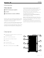
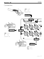
Descrizione
A Costruzione in multistrato di betulla ad incollaggio
fenolico, verniciatura poliuretanica.
B
2 Woofer da 15" ad alta efficienza.
C
Griglia di protezione in acciaio verniciato.
A
Montarbo
G
B
D Tubi di accordo.
E
Maniglia per il trasporto.
F
Pannello controlli e connessioni.
F
E
G Adattatore per supporto cassa (SM4).
D
B
C
ITALIANO
3
215 SA
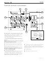
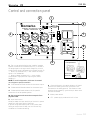
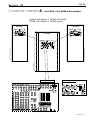
Pannello controlli e connessioni
1
2
6
Montarbo
MOD.
215 SA
POWER
POWERED PROCESSOR CONTROLLED
STEREO SUBWOOFER SYSTEM
800W
100Hz 20KHz
4
GND
7
FLAT
LIFT
L
L
LINK
L
INPUT
X-OVER OUT
4
5 6
2
8
1
3
R
R / mono
9
0
10
INPUT
LEVEL
R
8
7
3
FUSE F
5A
5
1 Selettore Flat / X-Over. Consente di inviare alle casse
acustiche "satellite", collegate all'uscita stereo (2), il segnale
a larga banda o solo la gamma alta. In entrambi i casi il
segnale è dipendente dal controllo di volume (5).
☞ Pulsante sollevato (crossover disinserito) = condizione
"flat": uscita a "tutta banda".
☞ Pulsante premuto (crossover inserito) = condizione
"x-over": uscita 100Hz÷20kHz del filtro passa alto (100Hz,
24 dB/oct.)
NOTA: Il pulsante "Flat / X-over" è interno; per commutarlo
servirsi di una punta (penna o matita)
2
2 prese XLR maschio sbilanciate per l'uscita stereo.
3
2 prese XLR femmina bilanciate per l'ingresso stereo.
4 2 prese XLR maschio bilanciate ("link") per il collegamento in parallelo di altre casse amplificate.
☛ Vedere i connettori e gli esempi di collegamento
alle pagine 17, 18, 19, 20 e 21.
5 Controllo livello ingresso.
Consente di adeguare la sensibilità di ingresso del finale
di potenza incorporato, al livello di uscita del mixer.
Se utilizzate un mixer Montarbo (o comunque un mixer
avente livello di uscita 0dB), regolate questo volume al
massimo (manopola girata in senso orario).
230V
50/60Hz
Sostituzione fusibile
Fusibile di servizio
Fusibile di riserva
6 Commutatore Ground/Lift: disinserisce la massa dell'amplificatore dal telaio (pur conservando il collegamento di
quest'ultimo a terra). Consente di ridurre i ronzii prodotti dai
cosiddetti "ground loops" (anelli di massa) quando si collegano più apparecchi.
7
Interruttore di rete.
8
Presa di rete con fusibile incorporato.
ITALIANO
4
215 SA
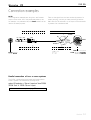
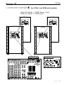
Esempi di collegamento
L’omnidirezionalità delle bassissime frequenze riprodotte dal
mod. 215SA (37÷100 Hz) rende l’installazione del subwoofer
per nulla critica.
Pur se è sempre preferibile posizionare il subwoofer vicino
alle casse acustiche, quando necessità di spazio o praticità
di montaggio lo richiedano il subwoofer può essere montato
anche a distanza dalle casse stesse (ad esempio: sotto il palco). Occorre tenere sempre presente che il rischio di rientri
acustici (feedback), con conseguenti inneschi o "code" indesiderate, aumenta a causa della maggiore estensione della
risposta in frequenza.
É quindi importante prestare attenzione ed installare il
subwoofer su strutture rigide, che non trasmettano vibrazioni ai microfoni.
Vi descriviamo qui di seguito alcune tra le configurazioni
possibili più comuni, che troverete illustrate alle pagine 18,
19 e 20 di questo manuale.
I nostri esempi mostrano il subwoofer 215SA insieme alle
casse amplificate Montarbo W20A usate come 'satelliti'.
Per quanto questo rappresenti un abbinamento ottimale,
il 215SA può essere usato - con risultati eccellenti - insieme
a qualunque altro sistema acustico.
Esempio A (pagina 18):
Un 215SA + due casse amplificate W20A
L'uscita stereo del crossover incorporato nel 215SA semplifica al massimo questo tipo di collegamento, solitamente
molto più complesso in altri sistemi.
NB: É consigliabile posizionare il subwoofer al centro rispetto alle due casse
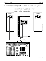
Esempio B (pagina 19):
Due 215SA + due casse amplificate W20A
É l'esempio di utilizzazione più classico, dove ogni subwoofer
può pilotare una o due casse acustiche autoamplificate.
uscite L/R del mixer ➟ ingressi 'R/MONO' dei due
215SA
uscite 'R' dei due 215SA ➟ ingressi delle due W20A
☛ Vedere esempio di collegamento B a pagina 19
• Utilizzare sempre cavi schermati.
• Collegare le uscite L ed R del mixer agli ingressi 'R/MONO'
dei due subwoofer 215SA.
• Collegare le uscite 'R' dei due subwoofer agli ingressi delle
due casse attive.
• Assicurarsi che il pulsante cross-over (1) sia premuto.
• Il controllo di volume ('input level') del subwoofer regola
anche il volume della cassa acustica. Porre il controllo di
volume di questa al massimo ed eventualmente regolarlo
per ottenere il miglior bilanciamento timbrico.
Esempio C (pagina 20):
Un 215SA + due casse amplificate W20A
Questa utilizzazione è più complessa, ma consente di rinforzare selettivamente le basse frequenze (ad esempio, solo per
le percussioni e le tastiere e non per i fiati e le voci).
NB: É consigliabile posizionare il subwoofer al centro rispetto alle due casse.
uscite L/R del mixer ➟ ingressi L/R del 215SA
uscite L/R del 215SA ➟ ingressi delle due W20A
uscita 'AUX' del mixer ➟ ingresso 'R/MONO' 215SA
uscita 'L' del mixer ➟ ingresso di una W20A
uscita 'R' del mixer ➟ ingresso di una W20A
☛ Vedere esempio di collegamento A a pagina 18
☛ Vedere esempio di collegamento C a pagina 20
• Utilizzare sempre cavi schermati.
• Collegare le uscite L ed R del mixer agli ingressi L ed R del
subwoofer.
• Collegare le uscite L ed R del subwoofer alle due casse
attive.
• Assicurarsi che il pulsante cross-over (1) sia premuto.
• Il controllo di volume ('input level') del subwoofer regola
anche il volume delle casse acustiche.
Porre il controllo di volume di queste al massimo ed eventualmente regolarlo per ottenere il miglior bilanciamento
timbrico.
• Utilizzare sempre cavi schermati.
• Il subwoofer è collegato ad una uscita AUSILIARIA (AUX)
del mixer e le casse attive alle uscite L ed R dello stesso.
Questo tipo di collegamento permette di utilizzare il subwoofer per estendere la risposta in frequenza solo in quegli
strumenti (es: batterie elettroniche, basso, tastiere) che
realmente ne hanno necessità. Per selezionare gli strumenti
da inviare al subwoofer usare i controlli di mandata AUX dei
corrispondenti canali di ingresso. Il controllo di volume del
subwoofer e quello dell’uscita AUX del mixer regolano solo
le basse frequenze.
ITALIANO
5
215 SA
NOTA:
Se disponete di un mixer amplificato provvisto di inserzioni,
e volete utilizzare il subwoofer senza escludere le uscite di
potenza, potete prelevare il segnale dalle stesse prese insert
mediante jack stereo, nei quali avrete precedentemente
CABLARE LA SPINA JACK STEREO COME ILLUSTRATO
collegato l'anella (RING) con la punta (TIP) cortocircuitandole, ed inviarlo agli ingressi del subwoofer mediante XLR
sbilanciati.
CABLARE IL CONNETTORE XLR MASCHIO COME ILLUSTRATO
☞
☞
TIP
RING
GND
12
12
12
12
12
12
12
12
2+
RING
1GND
GND
3 GND
2+
☞
☞
TIP
collegare punta e anello (cortocircuitarli)
PRESA INSERT
DEL MIXER.
1GND
RING = ANELLO
TIP = PUNTA
GND = MASSA
3 - GND
collegare 1 e 3 (cortocircuitarli)
1 GND = MASSA
2 + = CALDO
3 - = MASSA
INGRESSO (XLR FEMMINA)
215SA O DI UNA CASSA
SATELLITE AMPLIFICATA
Collegamento in parallelo di due o più
215A
Il sistema acustico 215SA è dotato di prese XLR maschio
e femmina in parallelo.
Ciò semplifica il collegamento in parallelo di più sistemi.
uscite L/R mixer ➟ ingressi 'R/MONO' di due 215SA
prese 'LINK' dei 215SA ➟ ingressi di altri 215SA
☛ Vedere l'esempio di collegamento a pagina 21
ITALIANO
6
215 SA
Importante !
Cura e manutenzione del prodotto:
• Posizionare la cassa lontano da fonti di calore (caloriferi o
qualsiasi altro oggetto che produca calore).
• Evitare di esporre la cassa alla irradiazione solare diretta, ad
eccessive vibrazioni e ad urti violenti.
• Evitare l'uso e il deposito in ambienti polverosi o umidi:
eviterete così cattivi funzionamenti e deterioramento anticipato delle prestazioni.
• Evitare l'uso vicino a fonti di interferenze elettromagnetiche (monitor video, cavi elettrici di alta potenza). Ciò potrebbe compromettere la qualità audio.
• Proteggere l'apparecchio dal rovesciamento accidentale di
liquidi o sostanze di qualsiasi tipo. In particolare nelle condizioni di utilizzo tipiche, prestare la massima attenzione alla
collocazione dell'apparecchio onde evitare che il pubblico, i
musicisti, i tecnici o chicchessia possa poggiare bicchieri,
tazze, contenitori di cibo o di bevande, posacenere o sigarette accese sull'apparecchio.
• Come asta di sostegno di una cassa satellite si raccomanda
di utilizzare il mod. SM4 Montarbo.
• Non togliere la griglia di protezione dalla cassa.
• Per rimuovere la polvere usate un pennello o un soffio
d'aria, non usate mai detergenti, solventi o alcool.
• Abbiate cura dei cavi di collegamento, avvolgeteli evitando nodi e torsioni.
Collegamento alla rete:
• Accertarsi che l'interruttore di rete sia in posizione "off".
• Accertarsi che la tensione di rete corrisponda a quellaindicata sul pannello.
• Collegare il cavo di alimentazione ad una presa di corrente
dotata di contatto di terra.
Collegamento al mixer:
Se il mixer ha uscite bilanciate XLR:
- utilizzare dei normali connettori XLR bilanciati.
Se il mixer ha uscite sbilanciate XLR:
- se il mixer non è un Montarbo, è bene accertarsi che le
uscite XLR del mixer siano sbilanciate a norme IEC 268 e
cioé: 1 = GND, 2 = HOT, 3 = GND.
Se il mixer ha uscite JACK sbilanciate:
- utilizzare adattatori Jack-XLR maschio sbilanciati a norme
IEC 268 e cioé: punta = pin 2, massa = pin 1, + = pin 3.
☛ Vedere i connettori alla pagina 17.
• Utilizzare sempre solo cavi SCHERMATI (cavi di segnale)
di adeguata sezione e di buona qualità.
• Prima di effettuare i collegamenti con il mixer, con i satelliti
o con altri sistemi accertarsi che tutti gli interruttori di rete
siano in posizione 'off'.
In tal modo si eviteranno fastidiosi rumori e picchi di segnale
talvolta pericolosi per le casse stesse.
• Non forzate i connettori ed i comandi.
ITALIANO
7
215 SA
The lighting flash with arrowhead symbol within an equilateral triangle, is intended
to alert the user to the presence of uninsulated 'dangerous voltage' within the
product's enclosure, that may be of sufficient magnitude to constitute a risk of
electric shock to humans.
The exclamation point within an equilateral triangle, is intended to alert the user
to the presence of important operating and maintenance (servicing) instructions.
IMPORTANT ! SAFETY INSTRUCTIONS
WARNING
In order to protect your own and others' safety and to avoid
invalidation of the warranty of this product, please read this
section carefully before operating this product.
- This product has been designed and manufactured for being operated as
active speaker system in the applications tipical of a sound reinforcement
system or of a sound recording system. Operation for purposes and in
applications other than these has not been covered by the manufacturer
in the design of the product, and is therefore to be undertaken at end
user's and/or installer's sole risk and responsability.
TO AVOID THE RISK OF FIRE AND/OR ELECTRIC SHOCK:
• Never expose this product to rain or moisture, never use it in proximity
of water or on a wet surface. Never let any liquid, as well as any object,
enter the product. In case, immediately disconnect it from the mains
supply and refer to servicing before operating it again.
• Before connecting this product to the mains supply, always make sure
that the voltage on the mains outlet corresponds to that stated on the
product.
• This product must be connected only to a grounded mains outlet
complying to the safety regulations in force via the supplied power cable.
In case the power cable needs to be substituted, use exclusively a cable of
the same type and characteristics.
• Never place any object on the power cable. Never lay the power cable
on a walkway where one could trip over it. Never press or pinch it.
• Never install the product without providing adequate airflow to cool it.
Never obstruct the air intake openings on it.
• In case the external fuse needs replacement, substitute it only with one
of the same type and rating, as stated on the product.
• Always make sure the On/Off switch is in its 'Off' position before doing
any operation on the connections of the product.
• Before attempting to move the product after it has been installed,
remove all the connections.
• To disconnect the power cable of this product from the mains supply
never pull the cable directly instead, hold the body of the plug firmly and
pull it gently from the mains supply outlet.
ENGLISH
INDEX
9
Introduction
__________________________________________
9
Description
__________________________________________
__________________________________________
10
Control and connection panel
__________________________________________
11 - 12
Connection examples
__________________________________________
13
Important !!!
__________________________________________
14 - 22
Appendix
__________________________________________
15
◗ Specifications
__________________________________________
16
◗ Block diagram
__________________________________________
17
◗ Connectors
__________________________________________
18
◗ Connection example A
__________________________________________
19
◗ Connection example B
__________________________________________
20
◗ Connection example C
__________________________________________
21
◗ Parallel Connection
__________________________________________
22
◗ Spare parts
__________________________________________
CAUTION!
This product does not contain user serviceable parts.
To prevent fire and/or electrical shock, never remove its cover.
For maintenance and servicing always refer to the official
Montarbo Distributor in your State or to qualified personnel
specifically authorised by the Distributor.
- Before placing the product on a surface of any kind, always make sure
that its shape and load rating will safely match the product's size and
weight. Never attempt to hang the product by any means not expressly
provided or approved by the manufacturer (i.e. ropes, chains, belts or
whatever medium, throgh carring handles, bolts, hooks or whatever).
In case the product is factory-fitted with specific mounting hardware,
always verify before installation that the lifting and/or hanging system
you intend to use is of a proper type and can carry the product weight
with the safety ratio required by the regulations in force.
- To avoid shocks, kicks, or whatever action, always reserve a protected
area with no access to unqualified personnel as installation site of the
product. In case the product is used near children and animals closest
supervision is necessary.
- This product can generate very high acoustic pressures which are
dangerous for the hearing system. Always avoid operation at loud levels
if anyone is excessively near to the product (at least 1 m of distance).
Never expose children to high sound sources.
ENGLISH
8
215 SA
Introduction
Active subwoofer
■ 800 W MosFet power amplifier
■ processor
■ stereo electronic crossover (24dB/oct)
Montarbo 215SA active subwoofer was designed to extend
the low frequency response of the W20A system. But at the
very first test, it proved to be the perfect companion for
loudspeakers of any make and model.
The two 15" units of the 215SA combine performance with
significant space savings, a key feature to many pro users.
solid 215SA absolutely don’t flex. Period. And efficiency,
precision and sonic imaging can be described truly
outstanding compared to many systems designed "the old
way" (where vibrations of cabinet walls steal acoustic
energy and give a dull, muddy, unprecise tone).
The stereo cross-over divides the signal and sends it to the
sub amp and the main PA outputs.
The MOSFET power amp delivers 800 W through our
unique processor, which protects both the speakers and
the sonic integrity of the system.
Nothing could be simpler than adding the 215SA to the
W20A, or to any other system. All it takes is the signal from
the mixing console plugged into its patch panel, and two
cables going to the main PA.
You can stack two 215SA subs one on top the other with
total safety (thanks to male/female integral stopblocks), or
place a full-range system on a pole that locks into the 215SA.
The cabinet is built with 18mm Finland birch multiply, as are
the many internal bracings designed to magnify stiffness
and rigidity of the box. Thanks to this bracing system, rock-
Description
A High grade birch plywood construction, phenolic glued;
polyurethane painted.
B
Two 15" high efficiency woofers.
C
Powder coated, perforated, steel grid.
A
G
Montarbo
B
D Tunig ports.
E
Side recessed handle.
F
Control and connection panel.
F
E
G Adaptor for satellyte supporting pole (SM4)
D
B
C
ENGLISH
9
215 SA
Control and connection panel
1
2
6
Montarbo
MOD.
215 SA
POWER
POWERED PROCESSOR CONTROLLED
STEREO SUBWOOFER SYSTEM
800W
100Hz 20KHz
4
GND
7
FLAT
LIFT
L
L
LINK
L
INPUT
X-OVER OUT
4
5 6
2
8
1
3
R
R / mono
9
0
10
INPUT
LEVEL
R
8
7
3
FUSE F
5A
5
1 Flat / X-over switch allowing the "satellite" speaker
systems, connected to the stereo output (2), to receive a
full-range signal or the upper audio range only. In both
conditions the signal is affected by the volume control (5)
☞ Button up (crossover off) = "flat" mode: the output
signal is "full bandwidth".
☞ Button pushed (crossover on) = "x-over mode":
100Hz÷20kHz high pass filter output signal (100Hz,
24dB/ oct.).
NOTE: To avoid misoperation, this button is recessed:
use a tip (pen or pencil) to switch it.
2
2 unbalanced XLR male sockets for the stereo output.
3
2 balanced XLR female sockets for the stereo input.
230V
50/60Hz
Fuse replacement
Service fuse
Spare fuse
4 2 balanced XLR male sockets (Link) for parallel
connection of active speaker systems.
6 Ground /Lift switch: this switch allows to lift signal
ground from chassis ground (but the chassis is still
connected to the safety ground). This allows to lower
annoying hums caused by "ground loops" when more
units are connected.
☛ See connectors and connection examples from
7
Mains power switch.
page 17 to 21.
8
I.E.C. power supply socket with built-in fuse.
5 Input level control.
Allows to adapt the input sensitivity of the built-in power
amplifier to the output level of the mixer.
If you are using a Montarbo mixer (or any other mixer
having an output level of 0dB), turn this control fully
clockwise to its maximum setting.
ENGLISH
10
215 SA
Connection examples
The very low frequency range reproduced by the subwoofer
model 215SA (37÷100 Hz) is essentially omnidirectional
allowing easy installation of the enclosure.
In most cases the subwoofer can be placed near to the loudspeaker system, but when space or set up reason dictate it,
the subwoofer can be positioned at some distance from the
speaker system (e.g.: under the stage floor).
You must always consider that the extended low frequency
range increases the risk of acoustic feedback, with
undesired "howls" and reduced clarity. It is thus essential
to place the subwoofer on a rigid structure, that does not
transmit vibrations to the microphones.
Some connection examples, among the most common
possible configurations, are described here below and also
illustrated on pages 18, 19 and 20 of this manual.
Our examples are showing the 215SA subwoofer enclosure
in conjunction with the Montarbo powered speakers W20A
used as "satellite" enclosures.
However this represents an optimum combination, the
215SA can be added with excellent results to any speaker
system.
Example B (page 19):
Two 215SA + two W20A active systems
This is the most typical configuration: each subwoofer can
drive one or two self-powered speaker enclosures.
mixer 'L/R' outputs ➟ 'R/MONO' inputs of two 215SA
215SA 'R' outputs ➟ inputs of the two W20A
☛ See connection example B on page 19
• Always use shielded cables
• Connect the L - R outputs of the mixer to the 'R/MONO'
inputs of the two 215SA subwoofers.
• Connect the 'R' outputs of the two 215SA to the inputs
of the two active systems.
• Make sure the cross-over button (1) is pushed on each
215 SA
• The subwoofers level controls adjust also the speaker
system’s volumes. First set the speaker system's volume
controls to their maximum position, then eventually adjust
them to obtain the desired tonal balance.
Example C (page 20):
Example A (page 18):
One 215SA + two W20A active systems
One 215SA + two W20A active systems
This is a more complex configuration which enables selective
enhancement of the low-frequencies (for example, only on
drums and keyboards, not on voices or brasses).
Note: It is advisable to place the subwoofer in the center,
between the two speaker systems.
The complex connections usually required for this configuration with other systems are made extremely simple with
our 215SA thanks to the L/R outputs of the built-in stereo
electronic cross-over.
Note: It is advisable to place the subwoofer in the center,
between the two speaker enclosures.
mixer L/R outputs ➟ 215SA L/R inputs
215SA L/R outputs ➟ inputs of the two W20A
☛ See connection example A on page 18
• Always use shielded cables
• Connect the L-R outputs of the mixer to the L-R inputs of
the 215SA.
• Connect the L-R outputs of the 215SA to the inputs of
the 2 active systems. This set-up allows them to benefit from
the increase in dynamic range provided by the electronic
crossover of the 215SA.
• Make sure the cross-over button (1) is pushed
• The subwoofer's level control adjusts also the speaker
system’s level. First set the speaker system's volume controls
to their maximum position, then adjust them to obtain the
required tonal balance.
mixer 'AUX' output ➟ 215SA 'R/MONO' input
mixer 'L' output ➟ W20A input
mixer 'R' output ➟ W20A input
☛ See connection example C on page 20
• Always use shielded cables
• Connect the AUXILIARY output of the mixer to the
'R/mono' input of the 215SA.
• Connect the L and R outputs of the mixer to the two
speaker systems respectively.
• This type of set-up allows to use the subwoofer to extend
the low frequency response of only those instruments that
really need it (e.g. drum machines, bass, keyboards). These
instruments are selected by means of the AUX send controls
on the corresponding channels. The subwoofer's volume
control and the mixer's AUX output level control adjust only
the very low frequencies.
ENGLISH
11
215 SA
Connection examples
NOTE:
Our configuration examples are using the L and R master
outputs of the mixer, but if they are already taken up (as,
for example, in a powered mixer) the insert sockets can be
used to the same purposes.
WIRE THE STEREO JACK PLUG AS SHOWN
Take out the signal from the insert sockets by means of a
stereo jack plug, in which you have previously joined the
RING with the TIP and send it to the inputs of the subwoofer
by means of an unbalanced XLR.
WIRE THE XLR MALE CONNECTOR AS SHOWN
☞
☞
2+
TIP
RING
GND
12
12
12
12
12
12
12
12
1GND
RING
1GND
GND
3 GND
connect ring with tip (shortcircuit)
INSERT SOCKET
OF THE MIXER.
2+
☞
☞
TIP
3 - GND
connect 1 with 3 (shortcircuit)
1 GND = GND
2 + = HOT
3 - = GND
INPUT (XLR FEMALE) OF A
215SA OR OF A POWERED
SATELLITE SPEAKER
Parallel connection of two or more systems
The 215SA is equipped with XLR male and female sockets
wired in parallel. This makes daisy-chaining easier.
mixer L/R outputs ➟ 'R/MONO' inputs of two 215SA
215SA 'link' ➟ 215SA 'R/MONO' input.
☛ See connection example on page 21
ENGLISH
12
215 SA
Important !
Product Care and Maintenance:
Power supply connection:
• Never expose the enclosure to heat sources such as radiators
or other products that produce heat.
• make sure the mains power switch is off ('0') before
starting any connection.
• Never expose the enclosure to direct sunlight, excessive
vibrations or mechanical shocks.
• check that mains voltage corresponds to the voltage
indicated on the panel.
• always connect the power cord to a grounded outlet.
• Avoid operating and storing the enclosure in dump or dusty
places: this will avoid malfunctions, premature degrading of
specifications.
• Avoid using the enclosure close to strong sources of
electromagnetic interferences (e.g. video monitors, high
power electrical cabling). This may lead to degradation of
audio quality.
• Care should be taken so that objects do not fall and liquid
are not spilled into the enclosure. In public event don't let
people, musicians, technicians or anyone put glasses, cups,
ashtrays or cigarettes on the enclosure.
• As satellite supporting pole we recommend the Montarbo
SM4.
Connection to the mixer:
If the mixer has XLR balanced outputs:
- use standard balanced XLR connectors.
If the mixer has XLR unbalanced outputs:
- in this case, unless you are using a Montarbo mixer, make
sure that the XLR outputs on the mixer are unbalanced to
IEC 268 standard: 1 = GND, 2 = HOT, 3 = GND.
If the mixer has JACK unbalanced outputs:
- use suitable Jack-XLR male adapters unbalanced according
to IEC 268: tip = pin 2, ground = pin 1, + = pin 3.
• Always leave the protective grille mounted on the
enclosure.
☛ See 'connectors' at page 17.
• Use a soft brush or a jet of air to clean the enclosure.
Do not use alcohol, solvents or detergents.
• Always use only heavy gauge, high quality SHIELDED
cables (signal cables).
• Take care of your connector cables. Make sure that they
are not damaged, knotted or twisted.
• Do not force the connectors and the controls.
• Always make sure that the mixer, the 215SA and
any other powered enclosure are switched off before
connecting them.
This shall to avoid annoying noises and signal peaks, which
can also be dangerous for the enclosures themselves.
ENGLISH
13
215 SA
APPENDIX
15
Specifications
__________________________________________
16
Block
diagram
__________________________________________
__________________________________________
17
Connectors
__________________________________________
18
Connection
example A
__________________________________________
19
Connection
example B
__________________________________________
20
Connection
example C
__________________________________________
21
Parallel
Connection
__________________________________________
22
Spare
parts
__________________________________________
APPENDIX
14
215 SA
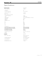
Specifications
Speaker System
bass-reflex
• Power Handling
1000W
• Impedance
4Ω
• Frequency Response
37Hz ÷ 100Hz
• Sensitivity (1W, 1m)
102 dB
• Max. S P L:
130 dB
• Built-in electronic crossover:
Crossover frequency
Slope
• Components:
Nominal diameter
Frequency range
Power capacity
Sensitivity
Rated impedance
Net weight
THIELE/SMALL PARAMETERS
fs
Re
Qms
Qes
Qts
Vas
ηo
B.l
SD
Xmax
Pe
100Hz
24dB/octave
2 x 15" WOOFER MOD. 15 PK 40
15"
37÷2000Hz
600W
99dB
8Ω
8 Kg
37Hz
5,6 Ω
6,38
0,304
0,290
0,215m3
3,45%
19,05T/m
0,085m2
± 3,8mm
600W
• Connections:
XLR
• Power supply (Europe and Asia)
• Power supply (USA and Canada)
230V AC 50÷60Hz
117V AC 50÷60Hz
• Fuse (Europe and Asia)
• Fuse (USA and Canada)
F 5 AL
F 10 AL
• Dimensions (w x h x d):
50,5 x 87,5 x 49,5 cm
• Weight:
59 kg
Amplifier
MOSFET
• Max. output power:
800 W continuous
1000 W peak
• Frequency Response:
37Hz ÷100Hz ±1dB
• Input Impedance
10kΩ (balanced)
• Input Sensitivity
0dB (775mV)
• Equivalent input noise
-110dB
APPENDIX
15
215 SA
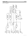
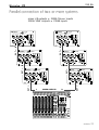
Block diagram
APPENDIX
16
215 SA
Connectors
1 GND Ground
2+
Hot
3Cold
(standard IEC 268)
2
3
BALANCED XLR
MALE CONNECTOR
1
▲
BALANCED XLR
FEMALE SOCKETS
Montarbo
▲
MOD.
215
POWER
POWERED PROCESSOR CONTROLLED
STEREO SUBWOOFER SYSTEM
80
100Hz 20KHz
2
2
3
L
▲
BALANCED XLR
FEMALE CONNECTOR
BALANCED XLR
MALE SOCKETS
L
LINK
1
1
2
3
3
▲
▲
1
X-OVER OUT
INPUT
FLAT
L
▲
4
▲
1 GND Ground
2+
Hot
3Cold
(standard IEC 268)
1
2
2
1
1
3
3
2
3
5 6
3
2
1
R
R / mono
0
10
INPUT
LEVEL
R
▲
UNBALANCED XLR
MALE SOCKETS
▲
UNBALANCED XLR
FEMALE CONNECTOR
1 GND
2+
3 GND
Ground
Hot
Ground
APPENDIX
17
215 SA
Connection example A:
one 215SA + two W20A active systems
mixer L / R outputs ➟ 215SA L / R inputs
215SA L / R outputs ➟ W20A inputs
W20A
W20A
Montarbo
POWER
SERIAL N.
5 6
4
7
2
OUT
OUT
LINK
10K
IN
LINK
IN
0,775V RMS
9
0
FUSE F
6,3 A
215SA
GND
CAUTION :
TO PREVENT RISK OF FIRE
ALWAYS REPLACE FUSES
WITH SAME TYPE AND RATINGS.
220V
POWER CONSUMPTION 1600W
50/60Hz
600+250W RMS
5 6
10
VOL.
7
LIFT
MOD.
215 SA
LINK
IN
LINK
10K
IN
0,775V RMS
4
5 6
0
10
H.F.
7
2
8
9
1
I
CAUTION :
TO PREVENT ELECTRICAL SHOCK,
DO NOT REMOVE COVERS.
NO USER - SERVICEABLE PARTS INSIDE.
REFER SERVICING TO QUALIFIED
SERVICE PERSONNEL.
FUSE F
6,3 A
GND
CAUTION :
0
Montarbo
OUT
OUT
3
8
9
1
XLR
1 GND
2
3
10
H.F.
I
CAUTION :
TO PREVENT ELECTRICAL SHOCK,
DO NOT REMOVE COVERS.
NO USER - SERVICEABLE PARTS INSIDE.
REFER SERVICING TO QUALIFIED
SERVICE PERSONNEL.
POWER
4
0
2
8
1
10
VOL.
3
7
2
9
0
W 20 A
SERIAL N.
5 6
3
8
1
MOD.
2 / WAY PROCESSOR CONTROLLED
ACTIVE SPEAKER SYSTEM
600+250W RMS
4
3
XLR
1 GND
2
3
Montarbo
W 20 A
MOD.
2 / WAY PROCESSOR CONTROLLED
ACTIVE SPEAKER SYSTEM
TO PREVENT RISK OF FIRE
ALWAYS REPLACE FUSES
WITH SAME TYPE AND RATINGS.
220V
POWER CONSUMPTION 1600W
50/60Hz
LIFT
0
POWER
800W RMS
SERIAL N.
POWERED PROCESSOR CONTROLLED
STEREO SUBWOOFER SYSTEM
100Hz 20KHz
GND
FLAT
LIFT
L
L
LINK
L
INPUT
X-OVER OUT
4
5 6
7
3
2
8
1
R
9
0
10
INPUT
LEVEL
R
220V
50/60Hz
FUSE F
5A
active subwoofer
biamped 2-way speaker system
biamped 2-way speaker system
R / mono
MASTER L - R OUTS
☞
STEREO EFF. RET.
Button PUSHED: x-over mode
230V
50 60Hz
FUSE T
0,5 A
1 EFF. FT/SW 2
100Hz 20KHz
MIC
MIC
MIC
MIC
MIC
R
MIC
R
(mono)
MIC
R
1
2
R
mute
A
mute
B
L
FLAT
R
R
R
0
48V D.C.
LINE
LINE
LINE
INSERT
INSERT
INSERT
LINE
LINE
LINE
MONO
LINE
L
L
L
(mono)
(mono)
(mono)
1
6
7
GAIN
4
8
GAIN
6
4
2
8
2
8
15
15
MF
2
.75
2
.3
3 KHz
2
8
LF
2
2
15
15
4
6
B
C
0
10
4
6
0
10
4
6
C
4
6
0
10
0
10
2
D
pre
post
E1 4
2
2
15
4
6
8
LF
10
6
10
4
6
B
C
4
6
10
0
10
6
D
0
10
4
6
10
4
6
8
B
C
4
6
10
4
8
16
GAIN
6
2
4
8
10
0
10
D
15
15
2
2
8
2
2
15
15
2
2
8
MF
HF
15
2
2
2
15
15
2
2
8
MF
HF
0
15
15
2
2
0
10
LF
8
15
15
4
6
8
A
8
0
10
4
6
0
10
4
6
B
C
4
6
10
0
10
D
0
10
4
6
8
B
0
10
4
6
C
4
6
0
10
4
6
0
10
0
10
2
STEREO DIGITAL
EFFECTS PROCESSORS
2
2
8
0
10
0
10
4
6
15
15
2
2
D
0
10
4
6
8
C
4
6
0
10
0
10
D
0
10
4
6
8
E1/E2
3
9
6
6
6
3
3
3
dB 0
0
0 dB
3
3
3
6
6
9
9
9
12
12
12
15
15
15
18
18
18
2
1
5 6
7
8
9
6
0
10
4
6
LOAD
12
9
6
3
PROGRAMS SELECTOR
INPUT LEVEL
INPUT LEVEL
3
3
dB 0
dB 0
8
8
3
3
10
10
20
20
4
6
0
10
3
6
9
12
0
10
31
Hz
4
4
6
2
8
8
GAIN 4
8
on
4
6
0
10
2
A
8
GAIN 4
6
2
flat
on
A
8
63
125
250
500
1K
2K
4K
8K
16K
6
2
8
flat
6
2
12
9
6
3
0 dB
3
6
9
12
dB 0
10
2
pre
post
E1 4
6
X-OVER OUT
4
R
L
9
2
8
2
8
L
INPUT
LEVEL
B
9
E1
8
0
8
2
6
2
10
2
15
4
2
8
pre
post
E1 4
6
B
L
8
15
2
8
POWER
Montarbo
OUTPUTS
A
8
8
A
8
0
8
2
6
2
10
2
15
4
2
8
LF
8
15
2
8
pre
post
E1 4
6
8
A
8
0
8
2
6
2
10
0
15
4
2
8
2
8
15
2
8
LF
I
LIFT
CTRL ROOM
MASTER OUTPUTS
OUTPUTS
D
10
EXT. EFF. SEND
15
15
AUX SEND
D
8
6
2
8
8
2
8
1
6
4
2
8
MF
C
4
6
2
8
2
AUX SEND
4
10
8
8
8
15
2
EFF SEND
C
6
2
10
8
8
8
pre
post
E1 4
6
HF
8
0
8
2
2
2
10
0
15
2
2
8
2
15
2
8
0
2
8
A
8
pre
post
E1 4
6
2
14 15
GAIN
6
E2
LF
8
0
8
2
2
15
2
10
0
2
4
2
8
2
8
15 dB
15
2
8
2
2
8
0
2
MF
3 KHz
8
A
8
4
2
15
8
0
8
8
15
1.6
.18
8
15 dB
15
pre
post
E1 4
6
2
MF
8
0
8
2
2
10
HF
1.3
.3
2
8
0
15
.75
2
4
10
8
1.6
3 KHz
2
B
2
12 13
GAIN
6
2
8
15
8
A
8
2
D
LF
8
2
2
15
8
2
.18
8
15 dB
8
A
MF
8
15
2
1.3
1.6
.3
.18
8
10
8
1.3
.75
4
2
HF
2
8
8
15
2
10 11
GAIN
6
10
HF
2
8
4
2
10
HF
9
GAIN
6
AUX
LINK
L
(mono)
GND
L
L
8
10
4
6
0
10
2
A
8
4
6
0
10
2
HF
6
2
4
6
0
10
2
HM 2
8
HF
2
8
15
10
A
8
2
8
15
15
8
15
15
2
8
HM 2
2
8
2
8
15
2
EQ
OUT
8
8
15
15
APPENDIX
18
215 SA
Connection example B:
two 215SA + two W20A active systems
mixer L / R outputs ➟ 215SA 'R/MONO' inputs
215SA 'R' outputs ➟ W20A inputs
W20A
W20A
Montarbo
MOD.
POWER
1
OUT
OUT
LINK
LINK
10K
IN
9
0
IN
0,775V RMS
9
0
FUSE F
6,3 A
215 SA
220V
POWER CONSUMPTION 1600W
50/60Hz
LIFT
0
POWER
Montarbo
800W RMS
SERIAL N.
biamped 2-way speaker system
X-OVER OUT
4
5 6
7
3
8
2
1
R
9
0
10
INPUT
LEVEL
R
FUSE F
6,3 A
TO PREVENT RISK OF FIRE
ALWAYS REPLACE FUSES
WITH SAME TYPE AND RATINGS.
220V
POWER CONSUMPTION 1600W
50/60Hz
7
220V
50/60Hz
FUSE F
5A
GND
LIFT
0
215 SA
POWER
800W RMS
GND
L
INPUT
X-OVER OUT
4
5 6
7
3
8
2
1
R
R / mono
R
9
0
10
INPUT
LEVEL
FUSE F
5A
220V
50/60Hz
active subwoofer
Button PUSHED: x-over mode
230V
50 60Hz
FUSE T
0,5 A
1 EFF. FT/SW 2
100Hz 20KHz
MIC
MIC
R
MIC
R
(mono)
MIC
LINE
LINE
R
INSERT
INSERT
INSERT
LINE
1
2
R
LINE
mute
A
mute
B
L
FLAT
R
R
R
LINE
0
MONO
LINE
L
L
L
(mono)
(mono)
(mono)
1
6
7
GAIN
4
8
GAIN
6
4
2
8
2
8
15
15
MF
2
.75
2
.3
3 KHz
2
8
LF
2
2
15
15
4
6
B
C
0
10
4
6
0
10
4
6
C
4
6
0
10
0
10
2
D
pre
post
E1 4
2
2
15
4
6
8
LF
10
6
10
4
6
B
C
4
6
10
0
10
6
D
0
10
4
6
10
4
6
8
B
C
4
6
10
4
8
16
GAIN
6
2
4
8
10
0
10
D
15
15
2
2
8
2
2
15
15
2
2
8
MF
HF
15
2
2
2
15
15
2
2
8
MF
HF
0
15
15
2
2
0
10
LF
8
15
15
4
6
8
A
8
0
10
4
6
0
10
4
6
B
C
4
6
10
0
10
D
0
10
4
6
8
B
0
10
4
6
C
4
6
0
10
4
6
0
10
0
10
2
STEREO DIGITAL
EFFECTS PROCESSORS
2
2
8
0
10
0
10
4
6
15
15
2
2
D
0
10
4
6
8
C
4
6
0
10
0
10
D
0
10
4
6
8
E1/E2
4
9
6
6
6
3
3
3
dB 0
0
0 dB
3
3
3
6
6
9
9
9
12
12
12
15
15
15
18
18
18
2
1
5 6
7
8
9
6
0
10
4
6
LOAD
12
9
6
3
PROGRAMS SELECTOR
INPUT LEVEL
INPUT LEVEL
3
3
dB 0
dB 0
8
8
3
3
10
10
20
20
4
6
0
10
3
6
9
12
0
10
31
Hz
4
4
6
2
8
8
GAIN 4
8
on
4
6
0
10
2
A
8
GAIN 4
6
2
flat
on
A
8
63
125
250
500
1K
2K
4K
8K
16K
6
2
8
flat
6
2
12
9
6
3
0 dB
3
6
9
12
dB 0
10
2
pre
post
E1 4
6
X-OVER OUT
3
R
L
9
2
8
2
8
L
INPUT
LEVEL
B
9
E1
8
0
8
2
6
2
10
2
15
4
2
8
pre
post
E1 4
6
B
LIFT
L
8
15
2
8
I
POWER
Montarbo
OUTPUTS
A
8
8
A
8
0
8
2
6
2
10
2
15
4
2
8
LF
8
15
2
8
pre
post
E1 4
6
8
A
8
0
8
2
6
2
10
0
15
4
2
8
2
8
15
2
8
LF
CTRL ROOM
MASTER OUTPUTS
OUTPUTS
D
10
EXT. EFF. SEND
15
15
AUX SEND
D
8
6
2
8
8
2
8
1
6
4
2
8
MF
C
4
6
2
8
2
AUX SEND
4
10
8
8
8
15
2
EFF SEND
C
6
2
10
8
8
8
pre
post
E1 4
6
HF
8
0
8
2
2
2
10
0
15
2
2
8
2
15
2
8
0
2
8
A
8
pre
post
E1 4
6
2
14 15
GAIN
6
E2
LF
8
0
8
2
2
15
2
10
0
2
4
2
8
2
8
15 dB
15
2
8
2
2
8
0
2
MF
3 KHz
8
A
8
4
2
15
8
0
8
8
15
1.6
.18
8
15 dB
15
pre
post
E1 4
6
2
MF
8
0
8
2
2
10
HF
1.3
.3
2
8
0
15
.75
2
4
10
8
1.6
3 KHz
2
B
2
12 13
GAIN
6
2
8
15
8
A
8
2
D
LF
8
2
2
15
8
2
.18
8
15 dB
8
A
MF
8
15
2
1.3
1.6
.3
.18
8
10
8
1.3
.75
4
2
HF
2
8
8
15
2
10 11
GAIN
6
10
HF
2
8
4
2
10
HF
9
GAIN
6
AUX
LINK
L
(mono)
GND
L
48V D.C.
LINE
8
9
LIFT
L
LINK
L
MIC
7
1
☞
STEREO EFF. RET.
MIC
5 6
10
H.F.
2
FLAT
L
MASTER L - R OUTS
MIC
4
0
3
8
9
SERIAL N.
100Hz 20KHz
active subwoofer
R / mono
MOD.
POWERED PROCESSOR CONTROLLED
STEREO SUBWOOFER SYSTEM
GND
L
INPUT
0,775V RMS
215SA
LIFT
L
LINK
10
VOL.
CAUTION :
TO PREVENT RISK OF FIRE
ALWAYS REPLACE FUSES
WITH SAME TYPE AND RATINGS.
FLAT
L
10K
IN
IN
I
CAUTION :
GND
LINK
biamped 2-way speaker system
MOD.
100Hz 20KHz
LINK
TO PREVENT ELECTRICAL SHOCK,
DO NOT REMOVE COVERS.
NO USER - SERVICEABLE PARTS INSIDE.
REFER SERVICING TO QUALIFIED
SERVICE PERSONNEL.
215SA
POWERED PROCESSOR CONTROLLED
STEREO SUBWOOFER SYSTEM
OUT
OUT
CAUTION :
Montarbo
600+250W RMS
5 6
1
XLR
1 GND
2
3
10
H.F.
I
CAUTION :
TO PREVENT ELECTRICAL SHOCK,
DO NOT REMOVE COVERS.
NO USER - SERVICEABLE PARTS INSIDE.
REFER SERVICING TO QUALIFIED
SERVICE PERSONNEL.
POWER
4
0
3
2
8
1
10
VOL.
W 20 A
7
3
2
8
SERIAL N.
5 6
4
7
MOD.
2 / WAY PROCESSOR CONTROLLED
ACTIVE SPEAKER SYSTEM
600+250W RMS
5 6
4
3
2
XLR
1 GND
2
3
Montarbo
W 20 A
SERIAL N.
2 / WAY PROCESSOR CONTROLLED
ACTIVE SPEAKER SYSTEM
8
10
4
6
0
10
2
A
8
4
6
0
10
2
HF
6
2
4
6
0
10
2
HM 2
8
HF
2
8
15
10
A
8
2
8
15
15
8
15
15
2
8
HM 2
2
8
2
8
15
2
EQ
OUT
8
8
15
15
APPENDIX
19
215 SA
Connection example C:
one 215SA + two W20A active systems
mixer 'AUX' output ➟ 215SA 'R/MONO' input
mixer 'L' output ➟ W20A input
mixer 'L' output ➟ W20A input
W20A
W20A
Montarbo
MOD.
POWER
5 6
4
7
1
OUT
OUT
LINK
10K
IN
LINK
0,775V RMS
9
0
FUSE F
6,3 A
215SA
GND
CAUTION :
TO PREVENT RISK OF FIRE
ALWAYS REPLACE FUSES
WITH SAME TYPE AND RATINGS.
220V
POWER CONSUMPTION 1600W
50/60Hz
600+250W RMS
5 6
10
VOL.
7
LIFT
MOD.
215 SA
OUT
OUT
LINK
CAUTION :
TO PREVENT ELECTRICAL SHOCK,
DO NOT REMOVE COVERS.
NO USER - SERVICEABLE PARTS INSIDE.
REFER SERVICING TO QUALIFIED
SERVICE PERSONNEL.
IN
10K
LINK
IN
0,775V RMS
9
4
5 6
0
10
H.F.
7
3
2
8
1
9
I
FUSE F
6,3 A
GND
CAUTION :
0
Montarbo
8
1
XLR
1 GND
2
3
10
H.F.
I
CAUTION :
TO PREVENT ELECTRICAL SHOCK,
DO NOT REMOVE COVERS.
NO USER - SERVICEABLE PARTS INSIDE.
REFER SERVICING TO QUALIFIED
SERVICE PERSONNEL.
POWER
4
0
2
8
1
10
VOL.
3
7
2
9
0
IN
W 20 A
SERIAL N.
5 6
3
8
MOD.
2 / WAY PROCESSOR CONTROLLED
ACTIVE SPEAKER SYSTEM
600+250W RMS
4
3
2
XLR
1 GND
2
3
Montarbo
W 20 A
SERIAL N.
2 / WAY PROCESSOR CONTROLLED
ACTIVE SPEAKER SYSTEM
TO PREVENT RISK OF FIRE
ALWAYS REPLACE FUSES
WITH SAME TYPE AND RATINGS.
220V
POWER CONSUMPTION 1600W
50/60Hz
LIFT
0
POWER
800W RMS
SERIAL N.
POWERED PROCESSOR CONTROLLED
STEREO SUBWOOFER SYSTEM
100Hz 20KHz
GND
FLAT
LIFT
L
L
LINK
L
INPUT
X-OVER OUT
4
5 6
7
3
2
8
1
R
9
0
10
INPUT
LEVEL
R
FUSE F
5A
220V
50/60Hz
active subwoofer
biamped 2-way speaker system
biamped 2-way speaker system
R / mono
MASTER
L - R OUTS
AUX OUT
STEREO EFF. RET.
230V
50 60Hz
FUSE T
0,5 A
1 EFF. FT/SW 2
L
L
MIC
MIC
MIC
MIC
MIC
MIC
MIC
R
R
R
R
(mono)
1
2
mute
A
mute
B
L
R
R
R
0
48V D.C.
LINE
LINE
INSERT
LINE
LINE
INSERT
INSERT
LINE
L
LINE
L
(mono)
LINE
L
(mono)
MONO
7
4
8
GAIN
6
4
2
8
2
8
15
2
1.3
1.6
.3
MF
2
2
8
LF
2
2
15
15
4
6
B
C
0
10
4
6
0
10
4
6
C
4
6
0
10
0
10
D
10
4
6
0
10
4
6
8
B
4
6
10
C
0
10
6
0
10
4
6
10
4
6
8
B
C
4
6
0
10
0
10
2
D
15
4
6
4
8
8
2
15
MF
2
2
2
2
8
15
MF
15
2
2
10
0
10
6
0
2
STEREO DIGITAL
EFFECTS PROCESSORS
0
10
D
OUTPUTS
A
15
LF
8
A
0
10
4
6
0
10
4
6
B
C
4
6
10
0
10
D
0
10
4
6
8
B
0
10
4
6
C
4
6
0
10
2
2
0
10
D
0
10
4
6
9
9
6
6
3
3
3
dB 0
0
0 dB
3
3
3
6
6
9
9
9
12
12
12
15
15
15
18
18
18
10
E1
8
B
0
10
4
6
C
4
6
0
10
0
10
D
0
10
4
6
0
10
4
6
8
LOAD
12
9
6
3
PROGRAMS SELECTOR
INPUT LEVEL
INPUT LEVEL
3
3
dB 0
dB 0
8
8
3
3
10
10
20
20
4
6
0
10
3
6
9
12
0
10
31
Hz
4
4
6
2
8
8
GAIN 4
8
on
4
6
0
10
2
A
8
GAIN 4
6
2
flat
on
A
8
63
125
250
500
1K
2K
4K
8K
16K
6
2
8
flat
6
2
12
9
6
3
0 dB
3
6
9
12
dB 0
10
2
pre
post
E1 4
6
E1/E2
8
0
8
2
6
2
10
2
15
4
2
8
6
8
15
2
8
pre
post
E1 4
6
8
A
8
0
8
2
6
2
10
2
15
4
2
8
LF
8
15
2
8
pre
post
E1 4
6
8
A
8
0
8
2
6
2
10
0
15
4
2
8
2
8
15
2
8
LF
R
L
6
8
15
LEVEL
B
9
2
8
2
8
AUX SEND
D
8
4
6
15
8
8
15
2
6
EXT. EFF. SEND
4
2
8
15
2
8
8
15
8
4
2
8
0
1
2
C
6
2
8
2
2
AUX SEND
4
10
HF
2
8
15
15
2
EFF SEND
C
6
2
10
8
8
8
pre
post
E1 4
6
MF
8
15
0
8
2
2
2
10
2
15
2
8
pre
post
E1 4
6
2
HF
2
8
8
15
2
15
2
2
8
0
2
8
A
8
2
D
8
16
GAIN
6
E2
LF
8
0
8
2
2
15
4
2
10
0
2
15
2
8
2
15 dB
8
A
8
pre
post
E1 4
6
2
LF
4
10
15
8
2
8
15
8
0
2
MF
3 KHz
8
8
0
8
pre
post
E1 4
6
2
10
2
2
15
4
2
8
0
2
15
2
B
MF
15 dB
8
A
8
2
D
LF
8
2
2
2
.18
14 15
GAIN
6
2
HF
2
8
15
1.6
.3
8
15
8
2
2
8
15 dB
8
A
MF
3 KHz
2
8
15
.75
2
.18
8
10
HF
1.3
1.6
.3
8
15
15
15
.75
2
3 KHz
2
4
I
POWER
Montarbo
(mono)
12 13
GAIN
6
2
8
1.3
.75
.18
8
10
2
8
8
15
15
4
2
HF
2
8
8
10 11
GAIN
6
10
HF
2
8
4
2
10
HF
9
GAIN
6
CTRL ROOM
MASTER OUTPUTS
OUTPUTS
L
(mono)
1
6
GAIN
AUX
8
10
4
6
0
10
2
A
8
4
6
0
10
2
HF
6
2
4
6
0
10
2
HM 2
8
HF
2
8
15
10
A
8
2
8
15
15
8
15
15
2
8
HM 2
2
8
2
8
15
2
EQ
OUT
8
8
15
15
APPENDIX
20
215 SA
Parallel connection of two or more systems
mixer L / R outputs ➟ 215SA 'R/MONO' inputs
215SA 'LINK' outputs ➟ 215SA inputs
Montarbo
MOD.
215 SA
Montarbo
800W
POWER
POWERED PROCESSOR CONTROLLED
STEREO SUBWOOFER SYSTEM
100Hz 20KHz
215 SA
MOD.
800W
POWER
POWERED PROCESSOR CONTROLLED
STEREO SUBWOOFER SYSTEM
100Hz 20KHz
GND
FLAT
GND
FLAT
LIFT
L
L
LINK
LIFT
L
INPUT
L
X-OVER OUT
L
L
LINK
INPUT
X-OVER OUT
4 5 6
2
9
R
R
230V
50/60Hz
FUSE F
5A
Montarbo
MOD.
800W
100Hz 20KHz
GND
FLAT
8
1
9
0
10
INPUT
LEVEL
R
R / mono
215 SA
POWER
POWERED PROCESSOR CONTROLLED
STEREO SUBWOOFER SYSTEM
2
OUT ➩ IN
0
10
INPUT
LEVEL
7
3
▲
8
1
R / mono
230V
50/60Hz
FUSE F
5A
Montarbo
MOD.
215 SA
POWER
POWERED PROCESSOR CONTROLLED
STEREO SUBWOOFER SYSTEM
800W
100Hz 20KHz
GND
FLAT
LIFT
L
L
LINK
LIFT
L
INPUT
L
L
X-OVER OUT
L
LINK
INPUT
X-OVER OUT
4 5 6
2
9
R
230V
50/60Hz
FUSE F
5A
Montarbo
MOD.
215 SA
800W
POWER
POWERED PROCESSOR CONTROLLED
STEREO SUBWOOFER SYSTEM
100Hz 20KHz
GND
FLAT
7
2
8
1
9
0
10
INPUT
LEVEL
R
R / mono
OUT ➩ IN
0
10
INPUT
LEVEL
R
R / mono
3
▲
8
1
230V
50/60Hz
FUSE F
5A
Montarbo
MOD.
215 SA
POWER
POWERED PROCESSOR CONTROLLED
STEREO SUBWOOFER SYSTEM
800W
100Hz 20KHz
GND
FLAT
LIFT
L
L
LINK
LIFT
L
INPUT
L
X-OVER OUT
L
LINK
L
INPUT
X-OVER OUT
4 5 6
2
9
0
10
INPUT
LEVEL
R
R / mono
R
230V
50/60Hz
FUSE F
5A
L
MIXER OUTPUTS
R
PHANTOM
STEREO EFF. RET.
MIC
MIC
MIC
MIC
MIC
MIC
MIC
MIC
MIC
R
MIC
LINE
LINE
LINE
LINE
LINE
LINE
LINE
INSERT
INSERT
INSERT
INSERT
INSERT
INSERT
INSERT
R
R
LINE
2
mute
A
mute
B
L
L
(mono)
1
1
2
GAIN
4
3
GAIN
6
4
2
8
2
8
15
2
15
.75
2
.3
.3
MF
3 KHz
2
2
8
MF
8
15
LF
2
15
15
8
4
6
0
10
2
6
10
C
4
6
0
10
6
10
6
10
C
4
6
0
10
6
10
4
6
0
10
6
10
M
15
6
10
4
6
0
10
6
10
C
4
15
15
C
6
10
6
10
4
15
15
C
6
10
6
10
4
15
15
C
6
10
6
10
4
6
0
10
6
10
M
15
15
6
10
4
6
0
10
2
C
6
10
4
6
0
10
6
10
6
10
C
6
10
6
10
4
6
0
10
6
10
6
10
15
2
2
2
GAIN
6
2
4
8
8
15
15
2
2
15
15
2
2
MF
8
2
8
15
15
2
2
15
15
2
2
MF
8
8
2
4
6
0
10
2
8
6
2
8
0
0
2
2
STEREO DIGITAL
EFFECTS PROCESSORS
15
15
2
2
0
10
8
4
6
0
10
6
10
A
4
6
0
10
6
10
C
4
8
6
10
OUTPUTS
D
A
2
L
R
6
10
BAL
L
R
6
10
BAL
L
R
4
6
0
10
6
10
INPUT LEVEL
6
3
0
3
3
6
6
R
L
peak
+
0
L
peak
1
6
R
+
0
L
peak
2
6
R
+
0
L
peak
3
6
R
+
0
L
peak
4
6
R
+
0
L
peak
5
6
R
+
0
L
peak
6
6
R
peak
7
6
+
0
R
peak
8
6
+
0
9
6
+
0
peak
3
dB 0
3
3
10
9
15
15
15
18
18
18
6
L
R
B
6
0
10
A
8
6
10
6
B
0
10
8
4
6
0
10
L
R
2
8
A
6
0
10
2
125
250
4
6
0
10
500
L
R
6
0
10
2
15
L
peak
12 13
14 15
6
6
6
+
0
R
E1
6
+
0
6
+
0
+
0
4K
L
R
2
15
8K
16K
2
2
15
15
6
+
0
8
2
EQ
15
CTRL
ROOM
2
2
15
15
8
LF
4
6
0
10
2
8
2
15
VOL 4
6
2
8
PHONES
8
MONO 4
2
15
8
8
OUT
8
15
LM
8
LF
2
15
8
15
2
15
8
8
8
0
6
8
2
10
0
10
peak
STEREO EFFECTS RETURNS
E2
6
2K
2
15
8
HM 2
8
15
LM
6
10
BAL
peak
STEREO DIGITAL
EFFECTS PROCESSORS
16
1K
HF
8
2
8
8
4
0
2
BAL
2
15
8
HM 2
4
2
B
8
2
HF
8
10
A
8
B
8
BAL
BAL
4
6
2
10
4
2
8
4
0
63
GAIN 4
6
2
on
4
2
8
GAIN 4
8
flat
2
10
10
31
Hz
6
2
on
4
3
6
9
12
4
6
8
A
6
0
12
9
6
3
0 dB
3
6
9
12
dB 0
20
4
flat
BAL
peak
+
0
6
12
10
20
2
8
0
10 11
+
0
3
9
12
8
L
3
0 dB
9
12
12
9
6
3
INPUT LEVEL
3
8
2
BAL
9
6
LOAD
dB 0
8
4
0
2
E2
8
R
L
9
6
3
10
PROGRAMS SELECTOR
8
pre
post
E1 4
10
4
0
E1/E2
8
6
10
2
6
2
6
10
4
0
2
D
8
0
E2
8
C
8
8
2
10
4
0
2
4
0
2
6
6
10
I
POWER
LEVEL
B
9
dB 0
E1
15
2
B
10
4
pre
post
E1 4
8
0
4
0
0
2
6
A
8
CTRL ROOM
8
15
8
6
10
2
D
8
2
E2
8
C
6
6
10
6
10
4
0
2
10
4
4
0
2
B
8
0
0
pre
post
E1 4
10
4
A
8
8
15
230V
50/60Hz
Montarbo
8
LF
8
15
8
6
10
2
6
0
6
10
4
0
2
D
8
0
4
0
2
8
4
0
8
15
2
B
8
LF
8
15
8
4
0
2
M
8
15
2
E2
LF
MASTER OUTPUTS
OUTPUTS
D
8
15
8
AUX SEND
8
4
6
15
MF
8
6
EXT. EFF. SEND
4
2
8
C
10
0
1
2
8
2
AUX SEND
4
2
8
10
HF
2
8
EFF SEND
C
6
2
10
HF
2
8
8
pre
post
E1 4
8
PAN
15
2
10
4
0
2
2
8
0
M
C
D
6
2
2
2
8
2
15
2
B
8
4
0
pre
post
E1 4
E2
A
8
2
15
15
8
4
0
2
8
PAN
4
0
8
8
8
10
4
0
2
M
15
2
8
0
15
2
6
2
E2
8
2
D
4
8
10
16
AUX
E2
LF
15 dB
2
B
14 15
GAIN
6
2
HF
2
8
8
A
8
pre
post
E1 4
MF
2
8
8
4
0
2
2
LF
8
2
D
2
3 KHz
15
8
4
0
2
1.6
8
8
10
4
0
PAN
2
B
8
0
MF
2
8
15
.18
15 dB
2
A
6
2
2
8
8
2
E2
8
.3
8
LF
8
4
0
pre
post
E1 4
2
15
8
2
2
3 KHz
4
8
10
HF
1.3
.75
8
8
4
0
2
D
8
6
10
4
0
2
10
4
0
MF
8
2
6
0
PAN
2
B
15
1.6
GAIN
6
2
12 13
2
8
15
.18
15 dB
2
A
8
2
2
8
8
6
10
2
E2
M
LF
6
4
.3
8
10
0
0
pre
post
E1 4
8
2
15
8
2
2
3 KHz
4
8
10
2
8
1.3
.75
8
8
4
0
2
D
8
6
10
4
0
2
10
4
0
MF
8
2
6
0
PAN
2
B
15
1.6
10 11
GAIN
6
2
HF
2
8
15
.18
15 dB
2
A
8
2
2
8
8
6
10
2
E2
M
LF
6
4
.3
8
10
0
0
pre
post
E1 4
8
2
15
8
2
2
3 KHz
4
8
10
2
8
1.3
.75
8
8
4
0
2
D
8
6
10
4
0
2
10
4
0
MF
8
2
6
0
PAN
2
B
15
1.6
9
GAIN
6
2
HF
2
8
15
.18
15 dB
2
A
8
2
2
8
8
6
10
2
M
LF
6
4
pre
post
E1 4
.3
8
10
0
0
2
E2
2
15
8
2
D
2
3 KHz
4
8
10
2
8
1.3
.75
8
8
4
0
2
8
MF
8
10
4
0
PAN
15
2
8
0
2
B
15
1.6
8
GAIN
6
2
HF
2
8
15
.18
15 dB
2
A
6
2
2
8
8
2
E2
.3
8
LF
8
4
0
pre
post
E1 4
2
15
8
2
2
3 KHz
4
8
10
2
8
1.3
.75
8
8
4
0
2
D
8
MF
8
10
4
0
2
PAN
15
2
8
0
15
2
6
2
E2
2
B
15
1.6
7
GAIN
6
2
HF
2
8
15
.18
15 dB
2
A
8
pre
post
E1 4
2
8
8
4
0
2
.3
8
LF
8
2
D
2
15
8
4
0
2
2
3 KHz
4
8
10
2
8
1.3
.75
8
8
B
15
1.6
6
GAIN
6
2
HF
2
8
15
.18
15 dB
2
A
2
8
1.3
1.6
4
8
10
8
15
5
GAIN
6
2
HF
2
8
1.3
.75
.18
4
8
10
HF
2
8
GAIN
6
2
10
HF
4
FUSE F
5A
R
MONO
LINE
L
(mono)
9
R
R
LINE
L
(mono)
R
0
10
INPUT
LEVEL
L
1
R
LINE
L
(mono)
8
1
(mono)
MIC
48V D.C.
LINE
INSERT
2
230V
50 60Hz
FUSE T
0,5 A
1 EFF. FT/SW 2
L
MIC
R / mono
7
3
▲
8
1
OUT ➩ IN
R
4 5 6
7
3
▲
OUT ➩ IN
R
4 5 6
7
3
▲
OUT ➩ IN
OUT ➩ IN
R
4 5 6
7
3
▲
1
2
6
+
0
AUX
A
MASTER
B
6
+
0
L
R
VOL 4
6
2
6
8
0
+
0
10
TAPE
6
6
6
6
6
6
6
6
6
6
6
6
6
6
6
6
6
6
6
18
18
18
18
18
18
18
18
18
18
18
18
18
18
18
18
18
18
18
30
30
30
30
30
30
30
30
30
30
30
30
30
30
30
30
30
30
30
40
40
40
40
40
40
40
40
40
40
40
40
40
40
40
40
40
40
40
IN
OUT
L
L
R
R
APPENDIX
21
215 SA
Spare parts
B010010
A300151
D522151
A088677
A088676
B021102
D202152
B005010
D00119F
A300151
D521190
D52118T
STAND HOLDER
B010010
WOOFER 15" PK40 8 Ω
A300151
CONTROL & CONNECTION PANEL
D522151
AMPLIFIER CHASSIS:
D521190
POWER AMPLIFIER HEAT SINK
D52118T
POWER AMPLIFIER
D00119F
POWER TRANSFORMER
B005010
HANDLE ASSEMBLY
A088676
A088677
B021102
FUSE 5A
A600050
FUSE 10A
A600100
METAL GRID
D202152
APPENDIX
22
elettronica Montarbo srl
via G. di Vittorio 13
40057 Cadriano di Granarolo
Bologna, Italy
Tel. +39. 051. 76 64 37
Fax. +39. 051. 76 52 26
E-mail: [email protected]
Internet: www.montarbo.com
Le informazioni contenute in questo manuale
sono state attentamente redatte e controllate.
Tuttavia non si assume alcuna responsabilità
per eventuali inesattezze.
Questo manuale non può contenere una
risposta a tutti i singoli problemi che possono
presentarsi durante l'installazione e l'uso
dell'apparecchio. Siamo a vostra disposizione
per fornirvi eventuali ulteriori informazioni e
consigli.
Les indications contenues en ce manuel ont
été attentivement rédigées et contrôlées.
Toutefois nous n'assumons aucune responsabilité pour des éventuelles inexactitudes.
Ce manuel ne peut contenir une réponse
pour problèmes particuliers qui pourraient se
présenter lors de l’installation et de l’usage
de l’appareil. Nous sommes à votre disposition pour d’éventuels conseils et informations
supplémentaires.
La Elettronica Montarbo srl non può essere
ritenuta responsabile per danni o incidenti a
cose o persone, causati o connessi all’utilizzazione o malfunzionamento dell’apparecchio.
Elettronica Montarbo srl ne peut être
consideré responsable des dommages causés
à des personnes ou à des objects lors de l'utilisation du produit.
The information contained in this manual has
been carefully drawn up and checked.
However no responsibility will be assumed for
any inexactitude.
This manual can not cover all the possible
contingencies which may arise during
installation and use of the product.
Should further information be desired, please
contact us or our local distributor.
Die in dieser Bedienungsanleitung enthaltenen
Hinweise wurden sorgfältig bearbeitet und
korrigiert. Es wird jedoch keine Gewähr für
die Richtigkeit der Angaben übernommen.
Diese Bedienungsanleitung kann nicht alle
Richtlinien und Probleme berücksichtigen,
welche während der Aufstellung und
Verwendung des Gerätes entstehen können.
Sollten Sie Fragen haben, wenden Sie sich
bitte an uns oder an den für Ihr Land zuständigen Importeur.
Elettronica Montarbo srl can not be
considered responsible for damages which
may be caused to people and things when
using this product.
Las informaciónes contenidas en este manual
han sidos atentamente redactas y verificadas.
De todos modos no asumimos alguna
responsabilidad de eventuales inexactitudes.
Este manual no puede contener una respuesta
a todos los problemas que pueden presentarse
durante la instalación y el uso de estos
aparatos. Estamos a vuestra disposición para
facilitar informes y consejos.
Elettronica Montarbo srl no puede ser considerada responsable de daños que puedan ser
causados a personas o cosas derivados de la
utilizaciòn del aparato.
Die Elettronica Montarbo srl haftet nicht,
für Personen- oder Sachschäden die durch die
Verwendung des Gerätes entstehen.
CARATTERISTICHE E DATI TECNICI POSSONO ESSERE MODIFICATI SENZA PREAVVISO.
SPECIFICATIONS AND FEATURES ARE SUBJECT TO CHANGE WITHOUT PRIOR NOTICE.
ÄNDERUNGEN VORBEHALTEN. LAS CARACTERISTICAS Y LOS DATOS TECNICOS PUEDEN SUFRIR MODIFICACIONES SIN PREVIO AVISO. SOUS RESERVE DE MODIFICATIONS.