1
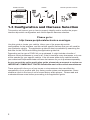
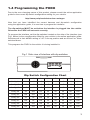
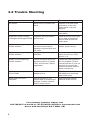
PXDX
Auxiliary Audio Input Interface
TOP VIEW
Instruction Manual
PROFESSIONAL INSTALLATION
STRONGLY ADVISED
Peripheral Electronics®,
a division of AAMP of America™
13160 56th Court Clearwater, Florida 33760
866-788-4237 in the US or 727-572-9255 ext.262 for international calls
[email protected]
©2007 AAMP™ of Florida, Inc.
rm01.12.07
Table of Contents
CHAPTER 1-Getting Started
Pages
1.1 Introduction
1
1.2 Precautions
1
1.3 Configuration & Harnesses
2
1.4 Programming the PXDX
3
CHAPTER 2-General Installation
2.1 Installation Location
4
2.2 Pre-Installation Checklist
4
2.3 Wiring Connections
4-5
2.4 Installation at Changer Location
5-6
2.5 Installation at Radio
6
CHAPTER 3 -Operation
3.1 Operation
7
3.2 Troubleshooting
8
3.3 Warranty
9
3.4 Warning
9
3.5 FCC Statement
9
Chapter 1- Getting Started
1.1 Introduction
Thank you for purchasing the PXDX Interface by Peripheral Electronics®. This
interface will allow you to connect a line level audio input directly into the vehicle’s
factory radio without the use of a noisy RF modulator. The PXDX interface is the
best way to add mobile video, satellite radio, MP3 players or other hand held media devices to your factory radio.
Please read this entire manual before attempting installation of the PXDX interface. Professional installation is recommended.
1.2 Precautions
(Important, Please Read)
To eliminate the risk of an electrical short, we recommend disconnecting the car
battery in most vehicles, except in the following situations:
• Vehicles equipped with on-board navigation should not have the car’s battery
disconnected. Doing so may cause loss of memory settings. These settings
would then have to be reprogrammed by an authorized car dealer for a fee to be paid by the vehicle’s owner. For these vehicles, we recommend extreme
caution when handling exposed 12V power or ground wires/connectors.
•Vehicles that incorporate a security-code protecting the radio. If the car’s battery or the radio’s power plugs are disconnected, the radio will not operate without re-entering the security-code. If you have access to the security-code, feel
comfortable disconnecting the battery and the radio’s power connectors. Other wise, do not disconnect the battery and exercise extreme caution while handling exposed 12V power or ground wires/connectors.
PROPER MOUNTING LOCATION
Securely install the interface in a location free from; heat, humidity, moving parts or
direct sunlight. Beware of hot-air flow from your vehicle’s climate control system.
We recommend securing the interface to a suitable location, free of sharp metal
edges, using; double sided tape, Velcro or wire ties.
1
PXDX interface
Cables
Vehicle specific harness
OR
1.3 Configuration and Harness Selection
This section will instruct you on how to properly identify and/or confirm the proper
interface dip-switch configuration and vehicle specific harness selection.
Please go to:
http://www.peripheralelectronics.com/apps
Use this guide to locate your vehicle, inform you of the proper dip-switch
configuration for the interface, and the vehicle specific harness that you will need for
your particular vehicle. The application guide will also be available by searching the
web site for the PXDX and clicking the application guide link.
Depending on the type of PXDX kit you purchased, it might include a bundle of
different vehicle harnesses or none at all. If the kit contains many harnesses, only one
will be needed for your specific vehicle. If the kit came without any vehicle harness,
your authorized Peripheral® dealer will have the harness for you to purchase separately.
As you consult the online application guide, please take a moment to review our
IMPORTANT COMPATIBILITY NOTES listed below each of the vehicle manufactures.
These notes will inform you of any issues or circumstances that can affect the
compatibility of our product with your factory audio system and accessories. Some
situations result in the loss of use of some factory audio players. Please read and
understand these notes before proceeding to the application guide.
2
1.4 Programming the PXDX
Due to the ever changing nature of this product, please consult the online application
guide for the current dip switch configuration setting for your vehicle.
http://www.peripheralelectronics.com/apps
Now that you have identified the correct harness and dip-switch configuration
using the application guide, it is now time to program the interface.
The dip-switches MUST be set before the interface is plugged into the vehicle.
Otherwise the PXDX will not work correctly.
To program the interface, set the dip-switches located on the side of the interface (see
Fig.1 below) to the congfiguration listed for your vehicle in the online application guide:
Switches are in their default setting of “off” in the up position and are turned “on” when
switched down.
This programs the PXDX to the vehicle it is being installed in.
DIN CONNECTOR / DIP SWITCH VIEW
Fig.1 Side view of Interface with dip switches
1 2 3 4 5 6 7 8
ON
DIP
Dip Switch Configuration Chart
1
2
3
4
5
6
7
8
Config #1
ON
off
off
ON
off
off
off
ON
Config. #2
ON
off
off
off
off
off
off
ON
Config. #3
off
off
off
ON
off
off
off
ON
Config. #4
off
ON
off
off
off
off
off
ON
Config. #5
ON
ON
off
off
off
off
off
ON
Config. #6
off
off
ON
off
off
off
off
ON
Config. #7
ON
off
ON
off
off
off
off
ON
22-PIN HARNESS VIEW
Config. #8
off
ON
ON
off
off
off
off
ON
Config. #9
ON
ON
off
ON
off
off
off
ON
3
Chapter 2- General Installation
2.1 Installation Location
Most installations will require you to remove the factory radio in order to plug in the vehicle
specific harness. Some vehicles may require you to connect the interface to a factory
pre-run CD changer cable. The location of these CD changer cables will vary by vehicle.
Some common locations of these cables are in the trunk, behind the glove box, and in or
under a center console. ( see Fig.2 below)
Common Connection Locations
PXDX
interface
OR
Docking Cable
Vehicle Specific Harness
(Sold Separately)
Refer to Application Guide
correct harness
V OL
DS P
TUN E
PWR
SEEK
S CAN
1
B AN D
DIS C
TA P E
2
3
IN F O
SEEK
TYP E
TR AF
4
AUTO
V OI
R DS
AUTO
EQ
5
6
Fig. 2
2.2 Pre-Installation Checklist
At this time and before beginning the installation:
• You have read and understand the precautions outlined in section 1.2
• You should have your radio’s security code.(when applicable, see section 1.2)
• The dip-switches on the interface should have been set with the proper configuration.
(see section 1.3)
• You should have in your possession the correct harness for your vehicle. (see sec. 1.3)
• You have determined your installation location. (see section 2.1)
If any of these steps has not been taken, STOP. Only when ALL of these steps have been
taken should you proceed with the rest of the installation.
2.3 Wiring Connections
Some vehicle specific harnesses require wiring connections that involve splicing of wires.
If you are not confident in making these connections to your radio’s wiring harness, we
recommend you seek professional installation. You can visit www.peripheralelectronics.com
and click on the dealer link at the top of the page to find an authorized professional installer.
4
Make these connections only after verifying the proper circuit on your radio harness with a
voltmeter. With the key OFF and the negative test lead of the voltmeter firmly touching a
bare metal chassis part of your car, begin probing the wires in the main radio harness with
the positive test lead. The constant 12V+ circuit should read a continuous 12 volts or higher.
Once you’ve identified the constant 12V+ circuit, strip back about 1/8” of the insulation. Now
take the positive test lead and insert it into the wire stranding so that you can now probe for a
suitable ground location in the dash cavity using the negative test lead. Bare chassis metal
is the recommended ground spot. The voltmeter will read a constant 12 volts or higher when
you have found a good ground point. Attach the BLACK ground wire to this spot with either
an existing bolt or screw or use a metal piercing screw. You also have the option of splicing
into the ground wire in the main radio harness. Probe the remaining wires with the negative
test lead until you again find a circuit that reads a constant 12 volts on the voltmeter. When
you’ve found a circuit that reads constant 12 volts, turn the dash light dimmer control to make
sure you have not probed the illumination dimmer circuit. If the circuit continues to read a
constant 12 volts or higher regardless of the dimmer position, you have found the ground
wire. If not, continue testing until you do. Some vehicles do not have a ground wire in their
main radio harness and instead ground through their mounting brackets to the dash. In these
cases, you will have to ground the black wire to the bare metal chassis inside the dash . Once
the ground wire is connected, please finish your wiring connections by splicing in the external
YELLOW wire from the vehicle specific harness.
Vehicle Specific Harnesses that require wiring connections:
PXHFD1 – connect the Yellow wire to constant 12V+ & connect the Black wire to ground.
PXHFD2 – connect the Yellow wire to constant 12V+ & connect the Black wire to ground.
PXHFD3 – connect the Yellow wire to constant 12V+ & connect the Black wire to ground.
PXHGM3 – connect the Yellow wire to constant 12V+ & connect the Black wire to ground.
PXHVW2 – connect both the Black and Black/White wires to ground.
PXHTY3 - cut green wires when using with 06 and later Toyota vehicles
2.4 Installation at the CD Changer Location
In this section you will learn how to install the PXDX in the factory CD changer location. If your
vehicle is equipped with a factory CD changer you will need to disconnect it from the factory prerun harness in order to connect the PXDX interface. If your vehicle is not equipped with a factory
CD changer, you will need to locate the factory pre-run harness. This may involve the removal of
the; center console, glove box, or carpeted side panels in the trunk. Please consult your vehicle’s
dealership or a local car audio professional for instruction or assistance with locating the factory CD
changer connection if necessary.
1. Connect your vehicle specific Harness to the factory pre-run CD changer harness in the
vehicle.
2. Make any necessary wiring connections on your vehicle specific harness.
section 2.3 for details on making these wiring connections.
Please see
3. Now that the interface is connected to the radio, you should test the operation of the interface
before permanently running the cable or re-assembling the dash. Connect the RCA cable or 3.5
mm cable with the 8 PIN connector to the PXDX interface. Turn on the factory radio and press the
button that would activate the factory CD changer to select the PXDX interface It may take up to
three minutes for the interface to initialize to the radio (this only happens the very first time you
select the interface). Once the PXDX has been selected, you should be able to hear the music
from your auxiliary source through your factory radio. If the audio level from the PXDX auxiliary input source is low, turn dip switch #6 ON to increase the level. With the operation of
the interface confirmed, you may continue with the installation. If you experience difficulties in
operation, please see our troubleshooting chart in section 3.2.
Continued on next page
5
4. Run the RCA cable from the interface to the desired location. Use caution to not cut, pinch, or
crimp the cable during this step. Avoid moving parts, vehicle wiring harnesses and areas of excessive heat when routing the cable.
5. Secure the interface in the vehicle using; double sided tape, Velcro or wire ties. Make sure to
check for proper clearance and avoid moving parts. Take into account the size of the interface and
the wire harness and do not force the interface and harness into a space that is too tight, damage
to the harness may result.
2.5 Installation at the Radio
In this section you will learn how to install the PXDX behind the radio. If your vehicle is
equipped with a factory CD changer or other external audio source, you will need to disconnect it from the back of the radio in order to connect the PXDX interface.
1. Carefully remove the radio from the vehicle. If your radio uses a Security Code, make sure
that you have the code before unplugging the radio. Some vehicles require the use of special
tools to remove the radio. Please consult your vehicle’s dealership or a local car audio professional for instruction or assistance with radio removal if necessary.
2. Make any necessary wiring connections on your vehicle specific harness. Please see
section 2.3 for details on making these wiring connections.
3. Connect the Vehicle Specific Harness to the CD changer port on the back of the radio. Be
sure to make a firm connection but do not force it. If there is difficulty making the connection,
please consult the application guide to confirm your vehicle specific harness selection.
4. Now that the interface is connected to the radio, you should test the operation of the interface
before permanently running the cable or re-assembling the dash. Connect the RCA cable or 3.5
mm cable with the 8 PIN connector to the PXDX interface. Turn on the factory radio and press the
button that would activate the factory CD changer to select the PXDX interface It may take up to
three minutes for the interface to initialize to the radio (this only happens the very first time you
select the interface). Once the PXDX has been selected, you should be able to hear the music
from your auxiliary source through your factory radio. If the audio level from the PXDX auxiliary input source is low, turn dip switch #6 ON to increase the level. With the operation of
the interface confirmed, you may continue with the installation. If you experience difficulties in
operation, please see our troubleshooting chart in section 3.2.
5. Run the RCA cable from the interface to the desired location. Use caution to not cut, pinch, or
crimp the cable during this step. Avoid moving parts, vehicle wiring harnesses and areas of excessive heat when routing the cable.
6. Secure the interface in the dash cavity behind the radio using; double sided tape, Velcro or
wire ties. Make sure to check for proper clearance and avoid moving parts. Take into account
the size of the interface and the wire harness and do not force the interface and harness into
a space that is too tight, damage to the harness may result.
8. Now that the interface is secured and the docking cable has been run, you may reinstall
the radio and replace any panels that may have been removed to access the radio.
6
Chapter 3- Operation
3.1 Operation
Selecting the PXDX Auxiliary input Source
To select the PXDX from the factory radio, press the button that would normally
activate the factory CD changer. This button varies by vehicle manufacturers. In
some applications the PXDX is accessed like an satellite receiver, In these cases
will the button that normally activates satellite to access the PXDX. In other
cases, the PXDX can be activated using the Mode button.
Once the PXDX interface is selected the audio from the input source will play
through the factory stereo system. Depending on your vehicle the factory radio
will display text indicating it is in Aux Mode, CD Mode, or XM mode when the
PXDX is selected.
7
3.2 Trouble Shooting
Symptom
Cause
Remedy
No Power
Blown fuse in vehicle fuse
block.
Replace fuse with same
amp rating. If the fuse
blows again, call tech
support.
No Power
Bad connection
Check cable and wiring
connection.
Alternator noise is heard
(Changes with Engine RPM)
Improper wiring creates a
ground loop
Install a Ground loop isolator or seek professional
service from a local car
audio shop.
Radio is not recognizing
PXDX interface
Bad cables or cables are
not connected properly
between converter box and
car radio
Check connection and
cables, push in firmly.
Radio is not recognizing
PXDX interface
Wrong configuration on the
interface
Select the right configuration for your car. (See
section 1.3)
Radio is not recognizing
PXDX interface
Yellow and black wires are
not connected to Constant
12V+ and Ground. (When
applicable)
Please read wiring instructions in chapter 2 of this
manual and see if your car
requires to connect the
yellow and black cable to
power and ground
Audio is low compared to
CD or Radio
Audio output is low on
added source
Flip dip switch #6 to the
ON position to boost the
input audio level.
Input Audio is Low or
Distorted
PXDX interface is connected with an external CD
changer or other external
factory audio source
Disconnect the factory
external audio source.
For consumer technical support call:
866-788-4237 in the US or 727-572-9255 ext.262 for international calls
Hours: 9:30 am-6:00 pm E.S.T. MON - FRI
8
3.3 Warranty
One Year Limited Warranty
The quality controls used in the manufacture of this product will ensure your satisfaction.
This warranty applies only to the original purchaser of this product from an authorized
Peripheral Electronics dealer.
This warranty covers any supplied or manufactured parts of this product that, upon inspection by Peripheral Electronics authorized personnel, is found to have failed in normal use
due to defects in material or workmanship. This warranty does not apply to installation
expenses.
Attempting to service or modify this unit, operating this unit under conditions other than the
recommended voltage will render this WARRANTY VOID.
Unless otherwise prescribed by law, Peripheral Electronics shall not be liable for any personal injury, property damage and or any incidental or consequential damages of any kind
(including water damage) resulting from malfunctions, defects, misuse, improper installation
or alteration of this product.
All parts of this Peripheral Electronics product are guaranteed for a period of 1 year as
follows:
Within the first 12 months from date of purchase, subject to the conditions above, Peripheral Electronics will repair or replace the product at their discretion, if it is defective in material
or workmanship providing it is returned to an Authorized Peripheral Electronic’s Dealer, with
PROOF OF PURCHASE from an authorized Peripheral Electronics dealer.
3.4 Warning:
This equipment may be reset by unintentional electrostatic discharge during operation.
Exposure to direct sunlight or extreme heat may cause damage or malfunction.
3.5 FCC Class B Radio Frequency
Interference Statement
This equipment has been tested and found to comply with the limits for a Class B digital
device, pursuant to Part 15 of FCC rules. These limits are designed to provide reasonable protection against harmful interference in a residential installation. This equipment
generates, uses, and can radiate radio frequency energy and, if not installed and used in
accordance with the instructions, may cause harmful interference to radio communications.
However, there is no guarantee that interference will not occur in a particular installation. If
this equipment does cause harmful interference to radio or television reception, which can
be determined by turning the equipment off and on, the user is encouraged to try to correct
the interference by one or more of the following measures:
1. Reorientate or relocate the receiving antenna.
2. Increase the separation between the equipment and receiver.
3. Connect the equipment into an outlet on a circuit different from that of which
the receiver is connected.
4. Consult the dealer or an experienced radio / television technical for help
Notice : The changes or modifications not expressly approved by the party responsible for
compliance could void the user authority to operate the equipment.
9
www.peripheralelectronics.com
Peripheral Electronics®,
a division of AAMP of America™
13160 56th Court Clearwater, Florida 33760
866-788-4237 in the US or 727-572-9255 ext.262 for international calls
[email protected]
©2007 AAMP™ of Florida, Inc.