1
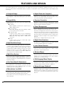
MULTIMEDIA PROJECTOR
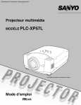
LV-7575
User’s Manual
TO THE OWNER
Before operating this projector, read this manual thoroughly
and operate the projector properly.
This projector provides many convenient features and
functions. Operating the projector properly enables you to
manage those features and maintain it in better condition for a
considerable time.
Improper operation may result in not only shortening the
product life, but also malfunctions, fire hazard, or other
accidents.
If your projector seems to operate improperly, read this
manual again, check operations and cable connections and try
the solutions in the “Troubleshooting” section in the end of
this booklet. If the problem still persists, contact the dealer
where you purchased the projector or the service center.
CAUTION
RISK OF ELECTRIC SHOCK
DO NOT OPEN
CAUTION: TO REDUCE THE RISK OF ELECTRIC
SHOCK, DO NOT REMOVE COVER (OR
BACK). NO USER-SERVICEABLE PARTS
INSIDE EXCEPT LAMP REPLACEMENT.
REFER SERVICING TO QUALIFIED SERVICE
PERSONNEL.
WARNING: TO REDUCE THE RISK OF FIRE OR ELECTRIC
SHOCK, DO NOT EXPOSE THIS APPLIANCE
TO RAIN OR MOISTURE.
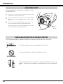
– This projector produces intense light from the projection
lens. Do not stare directly into the lens as much as
possible. Eye damage could result. Be especially careful
that children do not stare directly into the beam.
– Install the projector in a proper position. If not, it may result
in a fire hazard.
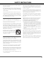
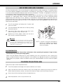
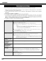
– Provide appropriate space on the top, sides and rear of the
projector cabinet for allowing air circulation and cooling the
projector. Minimum clearances must be maintained. If the
projector is to be built into a compartment or similarly
enclosed, the minimum distances must be maintained. Do
not cover the ventilation slots on the projector. Heat buildup can reduce the service life of your projector, and can
also be dangerous.
SIDE and TOP
REAR
1 m (3.3')
1 m (3.3')
1 m (3.3')
1 m (3.3')
THIS SYMBOL INDICATES THAT DANGEROUS
VOLTAGE CONSTITUTING A RISK OF ELECTRIC
SHOCK IS PRESENT WITHIN THIS UNIT.
– If the projector is not to be used for an extended time,
unplug the projector from the power outlet.
THIS SYMBOL INDICATES THAT THERE ARE
IMPORTANT OPERATING AND MAINTENANCE
INSTRUCTIONS IN THE USER’S MANUAL WITH
THIS UNIT.
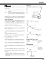
CAUTION ON HANGING FROM THE CEILING
CAUTION
Not for use in a computer room as defined in the Standard for
the Protection of Electronic Computer/Data Processing
Equipment, ANSI/NFPA 75.
Ne peut être utilisé dans une salle d’ordinateurs telle que
définie dans la norme ANSI/NFPA 75 Standard for Protection
of Electronic Computer/Data Processing Equipment.
NOTE FOR CUSTOMERS IN THE US
Hg LAMP(S) INSIDE THIS PRODUCT CONTAIN MERCURY
AND MUST BE RECYCLED OR DISPOSED OF ACCORDING
TO LOCAL, STATE OR FEDERAL LAWS.
2
Safety Precaution
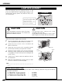
When hanging the projector from the
ceiling, clean the air intake vents, air filters,
and top of the projector periodically with a
vacuum cleaner. If you leave the projector
unclean for a long time, the dust will block
the operation of the cooling function, and it
may cause a breakdown or a disaster.
DO NOT SET THE PROJECTOR IN GREASY, WET, OR
SMOKY CONDITIONS SUCH AS IN A KITCHEN TO
PREVENT A BREAKDOWN OR A DISASTER. IF THE
PROJECTOR COMES IN CONTACT WITH OIL OR
CHEMICALS, IT MAY BECOME DETERIORATED.
READ AND KEEP THIS USER’S MANUAL FOR LATER USE.
SAFETY INSTRUCTIONS
All the safety and operating instructions should be read before
the product is operated.
Read all of the instructions given here and retain them for later
use. Unplug this projector from AC power supply before
cleaning. Do not use liquid or aerosol cleaners. Use a damp
cloth for cleaning.
This projector should be operated only from the type of power
source indicated on the marking label. If you are not sure of
the type of power supplied, consult your authorized dealer or
local power company.
Follow all warnings and instructions marked on the projector.
Do not overload wall outlets and extension cords as this can
result in fire or electric shock. Do not allow anything to rest on
the power cord. Do not locate this projector where the cord
may be damaged by persons walking on it.
For added protection to the projector during a lightning storm,
or when it is left unattended and unused for long periods of
time, unplug it from the wall outlet. This will prevent damage
due to lightning and power line surges.
Do not attempt to service this projector yourself as opening or
removing covers may expose you to dangerous voltage or
other hazards. Refer all servicing to qualified service
personnel.
Do not expose this unit to rain or use near water... for
example, in a wet basement, near a swimming pool, etc...
Do not use attachments not recommended by the
manufacturer as they may cause hazards.
Do not place this projector on an unstable cart, stand, or table.
The projector may fall, causing serious injury to a child or
adult, and serious damage to the projector. Use only with a
cart or stand recommended by the manufacturer, or sold with
the projector. Wall or shelf mounting should follow the
manufacturer’s instructions, and should use a mounting kit
approved by the manufacturers.
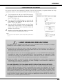
An appliance and cart combination should
be moved with care. Quick stops,
excessive force, and uneven surfaces
may cause the appliance and cart
combination to overturn.
Slots and openings in the back and bottom of the cabinet are
provided for ventilation, to insure reliable operation of the
equipment and to protect it from overheating.
Unplug this projector from wall outlet and refer servicing to
qualified service personnel under the following conditions:
a. When the power cord or plug is damaged or frayed.
b. If liquid has been spilled into the projector.
c. If the projector has been exposed to rain or water.
d. If the projector does not operate normally by following the
operating instructions. Adjust only those controls that are
covered by the operating instructions as improper
adjustment of other controls may result in damage and will
often require extensive work by a qualified technician to
restore the projector to normal operation.
e. If the projector has been dropped or the cabinet has been
damaged.
f. When the projector exhibits a distinct change in
performance-this indicates a need for service.
When replacement parts are required, be sure the service
technician has used replacement parts specified by the
manufacturer that have the same characteristics as the
original part. Unauthorized substitutions may result in fire,
electric shock, or injury to persons.
Upon completion of any service or repairs to this projector,
ask the service technician to perform routine safety checks to
determine that the projector is in safe operating condition.
The openings should never be covered with cloth or other
materials, and the bottom opening should not be blocked by
placing the projector on a bed, sofa, rug, or other similar
surface. This projector should never be placed near or over a
radiator or heat register.
This projector should not be placed in a built-in installation
such as a book case unless proper ventilation is provided.
Never push objects of any kind into this projector through
cabinet slots as they may touch dangerous voltage points or
short out parts that could result in a fire or electric shock.
Never spill liquid of any kind on the projector.
Do not install the projector near the ventilation duct of airconditioning equipment.
3
COMPLIANCE
Federal Communication Commission Notice
Multimedia Projector, Model: LV-7575
This device complies with Part 15 of the FCC Rules. Operation is subject to the following two conditions:
(1) This device may not cause harmful interference, and
(2) this device must accept any interference received, including interference that may cause undesired operation.
Note: This equipment has been tested and found to comply with the limits for a Class B digital device, pursuant to Part 15 of
the FCC Rules. These limits are designed to provide reasonable protection against harmful interference in a residential
installation. This equipment generates, uses and can radiate radio frequency energy and, if not installed and used in accordance
with the instructions, may cause harmful interference to radio communications. However, there is no guarantee that
interference will not occur in a particular installation. If this equipment does cause harmful interference to radio or television
reception, which can be determined by turning the equipment off and on, the user is encouraged to try to correct the
interference by one or more of the following measures:
–
–
–
–
Reorient or relocate the receiving antenna.
Increase the separation between the equipment and receiver.
Connect the equipment into an outlet on a circuit different from that to which the receiver is connected.
Consult the dealer or an experienced radio/TV technician for help.
Use of shielded cable is required to comply with class B limits in Subpart B of Part of FCC Rules.
Do not make any changes or modifications to the equipment unless otherwise specified in the instructions. If such changes or
modifications should be made, you could be required to stop operation of the equipment.
Canon U.S.A., Inc.
One Canon Plaza, Lake Success, NY 11042-1198, U.S.A.
Tel No. (516)328-5000
Canadian Radio Interference Regulations
This Class B digital apparatus meets all requirements of the Canadian Interference-Causing Equipment Regulations.
AC POWER CORD REQUIREMENT
The AC Power Cord supplied with this projector meets the requirement for use in the country you purchased it.
AC Power Cord for the United States and Canada:
AC Power Cord used in the United States and Canada is listed by the Underwriters Laboratories
(UL) and certified by the Canadian Standard Association (CSA).
AC Power Cord has a grounding-type AC line plug. This is a safety feature to be sure that the
plug will fit into the power outlet. Do not try to defeat this safety feature. Should you be unable
to insert the plug into the outlet, contact your electrician.
GROUND
THE SOCKET-OUTLET SHOULD BE INSTALLED NEAR THE EQUIPMENT AND EASILY ACCESSIBLE.
European Union (and EEA) only.
This symbol indicates that this product is not to be disposed of with your household waste, according to the WEEE
Directive (2002/96/EC) and your national law. This product should be handed over to a designated collection point,
e.g., on an authorized one-for-one basis when you buy a new similar product or to an authorized collection site for
recycling waste electrical and electronic equipment (EEE). Improper handling of this type of waste could have a
possible negative impact on the environment and human health due to potentially hazardous substances that are
generally associated with EEE. At the same time, your cooperation in the correct disposal of this product will
contribute to the effective usage of natural resources. For more information about where you can drop off your waste
equipment for recycling, please contact your local city office, waste authority, approved WEEE scheme or your
household waste disposal service. Your cooperation in the correct disposal of this product will contribute to the
effective usage of natural resources and will avoid incurring administrative sanctions according to art. 50 and
following of Italian legislative decree 22/97. For more information regarding return and recycling of WEEE products,
please visit www.canon-europe.com/environment.
(EEA: Norway, Iceland and Liechtenstein)
4
TABLE OF CONTENTS
FEATURES AND DESIGN
6
COMPUTER INPUT
24
PREPARATION
7
SELECTING INPUT SOURCE
SELECTING COMPUTER SYSTEM
PC ADJUSTMENT
24
25
26
NAME OF EACH PART OF PROJECTOR
SETTING-UP PROJECTOR
7
8
CONNECTING AC POWER CORD
POSITIONING PROJECTOR
ADJUSTABLE FEET
INSTALLING PROJECTOR IN PROPER POSITION
MOVING PROJECTOR
8
9
10
10
11
CONNECTING PROJECTOR
12
TERMINALS OF PROJECTOR
CONNECTING TO COMPUTERS
CONNECTING TO VIDEO EQUIPMENT
12
13
14
AUTO PC ADJUSTMENT
MANUAL PC ADJUSTMENT
26
27
PICTURE IMAGE SELECT
29
IMAGE LEVEL SELECT
PICTURE SCREEN ADJUSTMENT
PICTURE SCREEN SELECT
29
30
30
VIDEO INPUT
31
SELECTING INPUT SOURCE
SELECTING VIDEO SYSTEM
PICTURE IMAGE SELECT
31
32
33
IMAGE LEVEL SELECT
PICTURE SCREEN ADJUSTMENT
PICTURE SCREEN SELECT
33
34
34
BEFORE OPERATION
15
PICTURE IMAGE
35
REMOTE CONTROL OPERATION
15
PICTURE IMAGE ADJUSTMENTS
35
SETTING
38
SETTING MENU
38
APPENDIX
45
WIRELESS MOUSE
MAINTENANCE
45
46
LASER POINTER FUNCTION
REMOTE CONTROL BATTERIES INSTALLATION
TOP CONTROLS AND INDICATORS
ON-SCREEN MENU
HOW TO OPERATE ON-SCREEN MENU
FLOW OF ON-SCREEN MENU OPERATION
MENU BAR
15
16
17
18
18
18
19
BASIC OPERATION
20
TURNING ON/OFF PROJECTOR
20
TURNING ON THE PROJECTOR
TURNING OFF THE PROJECTOR
20
21
ADJUSTING SCREEN
ZOOM ADJUSTMENT
FOCUS ADJUSTMENT
LENS SHIFT ADJUSTMENT
KEYSTONE CORRECTION
PICTURE FREEZE FUNCTION
NO SHOW FUNCTION
P-TIMER FUNCTION
SOUND ADJUSTMENT
22
22
22
22
22
23
23
23
23
WARNING TEMP. INDICATOR
AIR FILTERS CARE AND CLEANING
CLEANING PROJECTION LENS
LAMP REPLACEMENT
LAMP REPLACE COUNTER
TROUBLESHOOTING
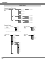
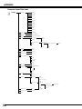
MENU TREE
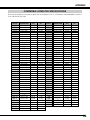
COMPATIBLE COMPUTER SPECIFICATIONS
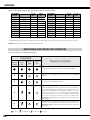
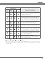
INDICATORS AND PROJECTOR CONDITION
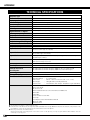
TECHNICAL SPECIFICATIONS
CONFIGURATIONS OF TERMINALS
OPTIONAL PARTS
LENS REPLACEMENT
PJ LINK NOTICE
DIMENSIONS
46
47
47
48
49
50
52
55
56
58
59
60
60
60
61
TRADEMARKS
● Apple, Macintosh, and PowerBook are trademarks or registered trademarks of Apple Computer,Inc.
● IBM and PS/2 are trademarks or registered trademarks of International Business Machines, Inc.
● Windows and PowerPoint are registered trademarks of Microsoft Corporation.
● Each name of corporations or products in the user’s manual is a trademark or a registered trademark of its respective corporation.
5
FEATURES AND DESIGN
This Multimedia Projector is designed with most advanced technology for portability, durability, and ease of use. This
projector utilizes built-in multimedia features, a palette of 1.07 billion colors, and matrix liquid crystal display (LCD)
technology.
◆
Compact Design
This projector is extremely compact in size and weight.
It is designed to carry and work anywhere you wish to
use.
◆
Compatibility
This projector accepts various video and computer input
signals such as:
● Computers
IBM-compatible or Macintosh computer up to
1600 x 1200 resolution.
● 6 Color Systems
NTSC, PAL, SECAM, NTSC 4.43, PAL-M, or PALN color system can be connected.
● Component Video
Component video signal, such as a DVD player
output high definition TV signals including 480i,
480p, 575i, 575p, 720p, 1035i, or 1080i, can be
connected.
● S-Video
S-Video signal, such as a S-VHS VCR output
signal, can be connected.
◆
High Resolution Image
This projector provides 1024 x 768 dots resolution for
computer input and 800 horizontal TV lines. Resolution
from a computer with more than XGA (1024 x 768) is
compressed into 1024 x 768 dots. This projector cannot
display an image of over 1920 x 1080 dots. When
resolution of your computer is over 1920 x 1080, lower
the resolution for a computer output.
◆
Multi-Scan System
This projector has the Multi-Scan System to conform to
almost all computer output signals quickly. There is no
need for a troublesome manual adjustment of frequency
and other settings.
◆
One-Touch Auto PC Adjustment
Incoming computer video signals are recognized and the
best adjustment is automatically set by the Auto PC
Adjustment function. No complicated setup is necessary
and the projection is always precise.
◆
Motor-driven Lens Shift
Projection lens can be moved up and down with the
motor-driven lens shift function. This function makes it
easy to provide projected image where you want.
Zoom and focus can also be adjusted with a motordriven operation.
6
◆
Digital Zoom (for Computer)
Digital Zoom function adjusts image size to approx. 1/4 ~
49 times of an original image size, allowing you to focus
on a crucial information at the presentation.
◆
Keystone Correction
Keystone correction function is provided to correct
distortion of the projected image allowing you to use the
projector without locational constraints.
◆
Power Management
Power management function is provided to reduce
power consumption when the projector is not in use.
The Power management function turns the projection
lamp off when the projector detects a signal interruption
or when no button is pressed for a certain period. The
projection lamp is automatically turned on again when
the projector detects a signal or any operation button is
pressed.
This projector is shipped with this function “ON.”
◆
Digital Visual Interface
This projector is equipped with the DVI 24-pin terminal
for connecting DVI output from a computer.
◆
Laser Pointer Function
The supplied Remote Control Unit has the Laser Pointer
function. This function helps you to make a smart
presentation on a projected screen.
◆
Wireless Mouse
The supplied Remote Control Unit has the Wireless
Mouse function for a connected computer. This function
enables you to operate both projector and computer
with the remote control unit only.
◆
Multilanguage Menu Display
Operation menu is available in 12 languages: English,
German, French, Italian, Spanish, Portuguese, Dutch,
Swedish, Russian, Chinese, Korean, or Japanese.
◆
Network Imager (Optional)
Equipped with the Network Imager, the projector can
display the image of the computer screen and the image
data stored in the computer via a network. The projector
can also be controlled and maintained through a web
browser.
PREPARATION
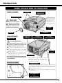
NAME OF EACH PART OF PROJECTOR
FRONT OF CABINET
SPEAKERS
TOP CONTROLS
AND INDICATORS
PROJECTION LENS
Kensington Security Slot
This slot is for a Kensington
lock used to deter theft of
the projector. For more
information, visit
http:www.kensington.com.
CAUTION
Do not turn on the projector
with the lens cap attached.
High temperature from light
beam may damage the lens
cap and result in fire hazard.
*Kensington is a registered trademark of
ACCO Brands Corporation.
AIR INTAKE
VENT
INFRARED
REMOTE RECEIVER
LENS CAP
BACK OF CABINET
POWER CORD
CONNECTOR
TERMINALS
AND CONNECTORS
INFRARED
REMOTE RECEIVER
EXHAUST VENT
HOT AIR EXHAUSTED !
Air blown from the exhaust vent is hot.
When using or installing the projector, the
following precautions should be taken.
● Do not put a flammable object near this
vent.
● Keep the rear grills at least 1 m (3.3’) away
from any object, especially from heatsensitive objects.
● Do not touch this area, especially screws
and metallic parts. This area will become hot
when the projector is in use.
This projector detects internal temperature
and automatically controls operating power
of the cooling fans.
CARRYING
HANDLE
LAMP COVER
When attaching the Network Imager
(optional) to the projector, remove the these
parts. Refer to the user’s manual of the
optional Network Imager.
BOTTOM OF CABINET
AIR INTAKE VENTS
This projector is equipped with cooling fans for protecting from
overheating. Pay attention to the following matters to ensure
proper ventilation and avoid a possible risk of fire and malfunction.
● Do not cover the vent slots.
● Keep this side clear of any objects. Obstructions may block
cooling the air.
ADJUSTABLE FEET
AND
FEET LOCK LATCHES
7
PREPARATION
SETTING-UP PROJECTOR
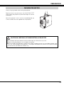
CONNECTING AC POWER CORD
This projector uses nominal input voltages of 100–120 V or
200–240 V AC and it automatically selects correct input
voltage. It is designed to work with single-phase power
systems having a grounded neutral conductor. To reduce
risk of electrical shock, do not plug into any other type of
power system.
If you are not sure of the type of power being supplied,
consult your authorized dealer or service station.
Connect the projector with all peripheral equipment before
turning it on. (See pages 12–14 for connection.)
CAUTION
Connect AC power cord (supplied) to the
projector.
The AC outlet must be near this equipment and
must be easily accessible.
For safety, unplug the AC power cord when the projector
is not in use. When the projector is connected to an
outlet with AC power cord, an appliance is in stand-by
mode and consumes a little electric power.
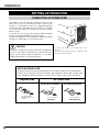
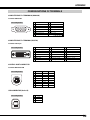
NOTE ON POWER CORD
AC power cord must meet the requirements of the country where you use the projector.
Confirm the AC plug type with the chart below and a proper AC power cord must be used.
If the supplied AC power cord does not match your AC outlet, contact your sales dealer.
Projector side
AC Outlet side
For the U.S.A. and Canada
For Continental Europe
Ground
To POWER CORD
CONNECTOR on your
projector.
8
To the AC Outlet.
To the AC Outlet.
(120 V AC)
(200–240 V AC)
PREPARATION
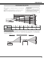
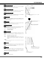
POSITIONING PROJECTOR
● This projector is designed to project on a flat projection
surface.
● Projector can be focused from 1.4 m (4.6’)–14.7 m (48.2’).
● Refer to the figure below to adjust the screen size.
A ROOM LIGHT
Brightness in a room has a great
influence on the picture quality. It is
recommended to limit ambient lighting
in order to provide the best image.
14.7m (48.2’)
11.0 m (36.1’)
7.3 m (24.0’)
3.6 m (11.8’)
100”
40”
400”
306”
200”
1.4 m (4.6’)
Max. Zoom
300”
229”
Min. Zoom
153”
76”
31”
Screen
Size
Max. Zoom
40”
100”
150”
200”
250”
300”
400”
Min. Zoom
31”
76”
114”
153”
190”
229”
306”
1.4 m (4.6’)
3.6 m (11.8’)
5.4 m (17.7’)
7.3 m (24.0’)
9.1 m (29.9’)
Distance
11.0 m (36.1’) 14.7 m (48.2’)
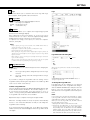
LENS SHIFT ADJUSTMENT
Projection lens can be moved up and down with the motor-driven Lens shift function. This function makes it
easy to provide projected image where you want. The U/D ratio can be adjusted 10:0–1:1 (see Figure below).
See page 22 for operation.
Highest (10 : 0)
Lowest (1 : 1)
9
PREPARATION
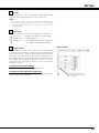
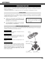
ADJUSTABLE FEET
Projection angle can be adjusted up to 10.5 degrees with the
ADJUSTABLE FEET.
1
Lift the front of the projector and pull the FEET LOCK
LATCHES in each side of the projector.
2
Release the FEET LOCK LATCHES to lock the ADJUSTABLE
FEET and rotate the ADJUSTABLE FEET to a proper height,
and tilt.
3
To retract the ADJUSTABLE FEET, lift the front of the
projector and pull and undo the FEET LOCK LATCHES.
Keystone distortion of the projected image can be corrected
by the Menu Operation. (See pages 22, 38.)
FEET LOCK
LATCHES
ADJUSTABLE FEET
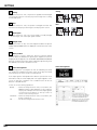
INSTALLING PROJECTOR IN PROPER POSITION
Install the projector properly. Improper installation may reduce the lamp life and cause a fire hazard.
10˚
Do not tilt the projector more than 10 degrees from side to side.
10˚
Do not put the projector on either side to project an image.
NO SIDEWAYS
20˚
20˚
10˚ 10˚
10˚ 10˚
10
When projecting vertically (up or down), keep the projector’s tilt within 10
degrees. Tilting more than 10 degrees in either direction may affect the projector
life.
PREPARATION
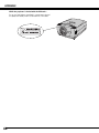
MOVING PROJECTOR
Use the Carrying Handle when moving the projector.
Replace the lens cap and retract the ADJUSTABLE FEET
when moving the projector to prevent damages to the lens
and cabinet.
When this projector is not in use for an extended period, put
it into a suitable case (not supplied with this projector).
CAUTION IN CARRYING OR TRANSPORTING A PROJECTOR
● Do not drop or bump the projector, otherwise damages or malfunctions may result.
● When carrying the projector, use a suitable carrying case.
● Do not transport the projector by courier or any other transport service in an unsuitable transport case.
This may cause damage to the projector. To transport the projector by courier or any other transport
service, consult your dealer for the best way.
11
CONNECTING PROJECTOR
TERMINALS OF PROJECTOR
This projector has input and output terminals on its back for connecting computers and video equipment. Refer
to the figures on pages 12–14 and connect properly.
COMPUTER AUDIO INPUT 1/
AUDIO MONITOR OUTPUT
JACK
This terminal is switchable and
can be used as Computer
Audio Input 1 or Audio Monitor
Output (variable).
Set up the terminal as either
Computer Audio Input 1 or
Audio Monitor Output properly
before using this terminal.
(See pages 13, 24.)
COMPUTER INPUT/MONITOR
OUTPUT TERMINAL (ANALOG)
COMPUTER INPUT
TERMINAL (DIGITAL)
COMPUTER AUDIO
INPUT 2 JACK
This terminal is switchable and
can be used as Computer Input
or Monitor Output. Set up the
terminal as either Computer
Input or Monitor Output properly
before using this terminal.
(See pages 13–14, 24.)
Connect a computer output
(Digital DVI-D type) to this
terminal.
The HD (HDCP Compatible)
signal can also be connected.
(See page 13.)
Connect an audio
output (stereo) from a
computer to this jack.
(See page 13.)
Note: This terminal outputs from the
5 BNC type computer input on
INPUT 2 jacks only.
Note: This terminal does not
output audio from INPUT 3.
R/C JACK
INPUT 1
RGB ANALOG IN/OUT
RGB DIGITAL
R/C JACK
USB CONNECTOR (Series B)
When controlling a computer
with the remote control unit of
this projector, connect USB
terminal of your personal
computer to this terminal. (See
page 13.)
AUDIO 1
IN/OUT
CONTROL PORT
RESET
AUDIO 2
G
B
R
VIDEO/Y
Cb/Pb
H/V
V
CONTROL PORT CONNECTOR
Cr/Pr
INPUT 2
VIDEO/Y Cb/Pb
Cr/Pr
R–AUDIO–L
RESET BUTTON
(MONO)
This projector uses a micro
processor to control the unit, and
only occasionally, this micro
processor may malfunction and
need to be reset. This can be done
by pressing the RESET button
with a pen, which will shut down
and restart the unit. Do not use
the RESET function excessively.
5 BNC INPUT JACKS
Connect component video
output (Y, Cb, Cr or Y, Pb,
Pr) from video equipment to
VIDEO/Y, Cb/Pb, and Cr/Pr
jacks or connect computer
output {5 BNC Type (Green,
Blue, Red, Horiz. Sync, and
Vert. Sync.)} from computer
to G, B, R, H/V, and V jacks.
(See pages 13–14.)
12
When using the Wired/
Wireless remote control unit
as wired, connect the Wired
remote control unit to this
jack with an Audio cable
(Mini Plug [stereo]; not
supplied).
INPUT 3
S–VIDEO
When controlling a computer
with the remote control unit
of this projector, connect the
mouse port of your personal
computer to this connector.
(See page 13.)
VIDEO INPUT JACKS
AUDIO INPUT JACKS
S-VIDEO INPUT JACK
Connect composite video
output from video equipment
to VIDEO/Y jack or connect
component video outputs to
VIDEO/Y, Cb/Pb, and Cr/Pr
jacks. (See page 14.)
Connect an audio output
from video equipment to
these jacks. (See page 14.)
Connect S-VIDEO output
from video equipment to
this jack. (See page 14.)
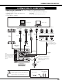
CONNECTING PROJECTOR
CONNECTING TO COMPUTERS
Cables used for connection (✽ = Cables or adapters not supplied with this projector.)
• VGA Cable (HDB 15 pin)
• Control Cable for PS2 Port ✽, or ADB Port ✽
• USB Cable
• DVI-Digital Cable (for Single Link T.M.D.S.) ✽
• BNC Cable ✽
• Audio Cables (Mini Plug [stereo] x 2) ✽
• Control Cable for Serial Port
IBM-compatible computer or Macintosh computer (VGA/SVGA/XGA/SXGA/SXGA+/WXGA/UXGA )
Desktop type
Monitor Output
Monitor Output Monitor Output Audio Output
or
Monitor Input
Audio
Cable ✽
(stereo)
DVI
Cable ✽
VGA Cable
BNC
Cable ✽
Laptop type
USB port
Serial port
Control Cable
for Serial Port
USB
Cable
Terminal
PS/2 port
ADB port
Control Cable Control Cable
for PS/2 Port ✽ for ADB Port ✽
Terminal
Terminal
Use one of these control
cables corresponding to the
terminal of your computer.
RGB ANALOG
IN/OUT
RGB DIGITAL
INPUT 1
RGB DIGITAL
RGB ANALOG IN/OUT
R/C JACK
NOTE:
This terminal is switchable.
Set up the terminal as
either Computer input or
Monitor output before
using this terminal.(See
page 24.)
CONTROL
PORT
CONTROL PORT
RESET
AUDIO 1
IN/OUT
COMPUTER
AUDIO IN 1 or 2
AUDIO 2
G
B
R
VIDEO/Y
Cb/Pb
Cr/Pr
H/V
V
USB
INPUT 2
VIDEO/Y Cb/Pb
Cr/Pr
R–AUDIO–L
S–VIDEO
AUDIO
OUT
(MONO)
NOTE:
This terminal is switchable. Set up
the terminal as either Computer
Audio Input 1 or Audio Monitor
Output (variable) before using this
terminal. (See page 24.)
INPUT 3
Audio Cable ✽
(stereo)
Terminals
of the Projector
Audio Input
External Audio Equipment
NOTE:
Unplug the power cords of both the projector and
external equipment from the AC outlet before
connecting cables. Turn a projector and peripheral
equipment on before computer is switched on.
Audio Amplifier
Audio Speakers
(stereo)
13
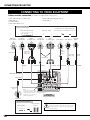
CONNECTING PROJECTOR
CONNECTING TO VIDEO EQUIPMENT
Cables used for connection (✽ = Cables not supplied with this projector.)
• Video Cable (RCA x 1 or RCA x 3) ✽
• BNC Cable ✽
• S-VIDEO Cable ✽
• Audio Cable (RCA x 2) ✽
• Audio Cable (Mini Plug [stereo]) ✽
• Scart Cable ✽
Video Source (Example)
Component video output equipment.
Video Cassette Recorder
RGB Scart
21-pin Output
Composite
Video Output
Component Video
Output
(Y, Cb/Pb, Cr/Pr)
Video Disc Player
(such as DVD players or high-definition TV sources.)
Component Video
Output
(Y, Cb/Pb, Cr/Pr)
Composite
Video Output
Audio Output
S-VIDEO
Output
Audio
Cable ✽
(stereo)
Video Cables
(RCA x 1 or
RCA x 3) ✽
Scart Cable ✽
Audio Output
Audio Cable
(RCA x 2) ✽
S-VIDEO
Cable ✽
AUDIO IN
S-VIDEO
BNC Cable ✽
VIDEO
Y - Cb/Pb - Cr/Pr VIDEO
Y - Cb/Pb - Cr/Pr
RGB ANALOG IN/OUT
AUDIO IN
INPUT 1
RGB DIGITAL
RGB ANALOG IN/OUT
R/C JACK
AUDIO OUT
AUDIO 1
IN/OUT
CONTROL PORT
RESET
AUDIO 2
G
B
R
VIDEO/Y
Cb/Pb
H/V
V
Cr/Pr
INPUT 2
VIDEO/Y Cb/Pb
Audio Cable ✽
(stereo)
Cr/Pr
R–AUDIO–L
S–VIDEO
(MONO)
NOTE:
This terminal is switchable.
Set up the terminal as either
Computer input or Monitor
output before using this
terminal.(See page 24.)
INPUT 3
Terminals
of the Projector
Audio Input
External Audio Equipment
Audio Amplifier
14
Audio Speakers
(stereo)
NOTE:
Unplug the power cords of both the projector and
external equipment from the AC outlet before
connecting cables.
BEFORE OPERATION
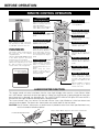
REMOTE CONTROL OPERATION
LASER POINTER
(DRAG ON) INDICATOR
Left Side
POWER BUTTON
Lights red while the laser
beam is emitted from the
Laser Light Window.
Lights green when dragged
to the “ON” position. (p.45)
Used to turn the projector on
or off. (pp.20–21)
MUTE BUTTON
Use to operate the AUTO PC
Adjustment function. (p.26)
AUTO PC ADJ. BUTTON
Used to mute the sound.
(p.23)
IMAGE BUTTON
Used to select the image
level. (pp.29, 33)
DRAG ON/OFF BUTTON
ALL OFF SWITCH
When using the remote control unit,
turn this switch to “ON.” And turn it
to “ALL OFF” when it is not in use.
Used to select the DRAG
ON/OFF position. (p.45)
KEYSTONE BUTTON
Used to correct keystone
distortion. (pp.22, 38)
LEFT CLICK BUTTON
INSIDE THE BATTERY
COMPARTMENT BOX
1
2
ON
3
4
Used as a PC mouse in
Wireless Mouse Operation.
This remote control unit provides the Press this button and the
DIP switches into the battery mouse pointer button to drag
the selected screen object.
compartment box.
Slide the SW4 (LASER ON/OFF switch) (p.45)
to the “OFF” position. The Laser
Pointer function is not operated.
LASER BUTTON
Set the Switches 1–3 as shown in
Used to operate the Laser
table below depending on the Code
Pointer function. The laser
No. that you want to select as the
beam is emitted when
remote control code. (See page 41.)
pressing this button for one
minute.
When using the Laser
DIP SWITCH SETTING
Pointer for more than one
SW4 ........ LASER ON/OFF
minute, release this button
SW1 SW2 SW3 Code No.
and press it again.
ON
ON
ON
ON
OFF
OFF
OFF
OFF
ON
ON
OFF
OFF
ON
ON
OFF
OFF
ON
OFF
ON
OFF
ON
OFF
ON
OFF
Code 1
Code 2
Code 3
Code 4
Code 5
Code 6
Code 7
Code 8
MOUSE POINTER
Used as a PC mouse in
Wireless Mouse Operation.
(p.45)
RIGHT CLICK BUTTON
Used as a PC mouse in
Wireless Mouse Operation.
(p.45)
LENS SHIFT BUTTON
Used to select the Lens Shift
function. (p.22)
WIRED REMOTE JACK
When using as a Wired
remote control unit, connect
an Audio cable (Mini Plug
[stereo]; not supplied) to this
jack.
Battery installation is required
when using as a Wired
remote control unit.
FOCUS BUTTON
Used to adjust focus. (p.22)
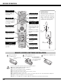
LASER POINTER FUNCTION
This remote control unit emits laser beam from the Laser Light Window when used as a Laser Pointer. When
the LASER button is pressed, the laser light goes on. When the LASER button is being pressed for more than
one minute or it is released, the light goes off. The LASER POINTER INDICATOR lights RED and LASER is
emitted with RED light to indicate the laser beam is being emitted.
The Laser emitted is the Cass II laser. Do not look into the Laser Light Window or shine laser beam onto
yourself or other people. The three marks shown below are caution labels for the laser beam.
CAUTION: Use of controls, adjustments, or performance of procedures other than those specified herein may
result in hazardous radiation exposure.
These caution labels are put on the remote control unit.
LASER POINTER INDICATOR
LASER LIGHT WINDOW
15
BEFORE OPERATION
D.ZOOM BUTTON
Used to select the
DIGITAL ZOOM +/–
mode and resize the
image. (p.30)
NO SHOW BUTTON
Used to turn the picture
into a black image. (p.23)
FREEZE BUTTON
OK BUTTON
Used to freeze the
picture. (p.23)
Used to execute the
selected item, or expand/
compress the image in
the DIGITAL ZOOM +/mode. (p.30)
Operating Range
Point the remote control unit
toward the projector (a Receiver
Window) when pressing any
button. Maximum operating
range for the remote control unit
is about 5 m (16.4’) and 60° in
front and rear of the projector.
POINT (VOLUME +/-)
BUTTONS
Used to select an item or
adjust a value in On-Screen
Menu. They are also used
to pan the image in the
DIGITAL ZOOM +/- mode.
(p.30)
The POINT LEFT/RIGHT
buttons are also used as
VOLUME +/- buttons.
(p.23)
MENU BUTTON
Used to select the MENU
Operation. (pp.18–19)
P-TIMER BUTTON
Used to operate the PTIMER function. (p.23)
60°
5m
(16.4’)
INPUT 1 BUTTON
Used to select an input
source (INPUT 1). (p.24)
ZOOM BUTTON
INPUT 2 BUTTON
Used to adjust zoom.
(p.22)
Used to select an input
source (INPUT 2).
(pp.25, 31)
COLOR MANAGEMENT
BUTTON
5m
(16.4’)
INPUT 3 BUTTON
Used to operate the Color
management function.
(pp.35–36)
60°
Used to select an input
source (INPUT 3). (p.31)
NETWORK BUTTON
Used to select a network
input (optional).
REMOTE CONTROL BATTERIES INSTALLATION
1
Open the battery
compartment lid.
Press the lid downward
and slide it.
2
Install new batteries into
the compartment.
3
Replace the compartment lid.
Two AA size batteries
For correct polarity (+ and
–), be sure battery terminals
are in contact with pins in
the compartment.
To insure safe operation, please observe following precautions:
● Use two (2) AA or LR6 type alkaline batteries.
● Always replace batteries in sets.
● Do not use a new battery with an used battery.
● Avoid contact with water or liquid.
● Do not expose the remote control unit to moisture, or heat.
● Do not drop the remote control unit.
● If a battery has leaked on the remote control unit, carefully wipe the case clean and install new batteries.
● Danger of explosion if battery is incorrectly replaced.
● Dispose of used batteries according to batteries manufacturers instructions and local rules.
16
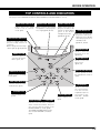
BEFORE OPERATION
TOP CONTROLS AND INDICATORS
This projector has CONTROL BUTTONS (TOP CONTROLS) and INDICATORS on its top.
LAMP MODE INDICATOR
WARNING TEMP. INDICATOR
READY INDICATOR
Lights when the Lamp
mode is set to “Silent”
mode. (p.41)
Blinks red when the internal
temperature of the projector
is too high. (pp.46, 56–57)
Lights green when the
projector is ready to be
turned on. And it blinks
green in the Power
management mode.
(pp.40, 46, 56–57)
LAMP REPLACE INDICATOR
Turns to orange when the
projection lamp reaches its
end of life.
Blinks orange when the lamp
cannot light up. (pp.48, 56–57)
LAMP INDICATOR
Becomes dim when the
projector is turned on.
And it becomes bright
when the projector is in
stand-by mode.
(pp.20–21, 56–57)
POWER BUTTON
Used to turn the
projector on or off.
(pp.20–21)
MENU BUTTON
Used to open or
close the On-Screen
Menu. (p.18, 19)
INPUT BUTTON
Used to select an
input source.
(pp.24, 31)
AUTO PC ADJ. BUTTON
LAMP MODE BUTTON
Used to operate the Auto
PC Adjustment function.
(p.26)
Used to select a Lamp
mode. (p.41)
LENS SHIFT BUTTON
Used to select the Lens
Shift function. (p.22)
OK BUTTON
ZOOM BUTTON
Used to adjust zoom.
(p.22)
FOCUS BUTTON
Used to adjust focus.
(p.22)
Used to execute
the selected item.
It is also used to
expand/compress
the image in the
DIGITAL ZOOM
mode. (p.30)
POINT (VOLUME + / – ) BUTTONS
Used to select an item or adjust a
value in On-Screen Menu. They are
also used to pan the image in the
DIGITAL ZOOM +/– mode. (p.30)
The POINT LEFT/RIGHT buttons are
also used as VOLUME +/– buttons.
(p.23)
17
BEFORE OPERATION
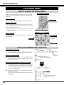
ON-SCREEN MENU
HOW TO OPERATE ON-SCREEN MENU
You can control and adjust this projector with On-Screen
Menu. Refer to the relevant pages to operate each
adjustment.
REMOTE CONTROL UNIT
1. DISPLAY MENU
POINT BUTTONS
Press the MENU button to display the On-Screen Menu.
Used to move the Pointer
UP/DOWN/ RIGHT/LEFT.
2. MOVING POINTER
Move the pointer (✽ see below) or adjust a value of an
item by pressing the POINT buttons on the top control
or on the remote control unit.
✽ The Pointer is an icon in the On-Screen Menu for selecting
an item. See figures in “FLOW OF ON-SCREEN MENU
OPERATION” below.
MENU BUTTON
OK BUTTON
Used to select the item.
TOP CONTROL
3. SELECT ITEM
Select an item or set the selected function by pressing
the OK button.
POINT BUTTONS
Used to move the
Pointer UP/ DOWN/
RIGHT/ LEFT.
MENU BUTTON
OK BUTTON
Used to select the item.
FLOW OF ON-SCREEN MENU OPERATION
Display ON-SCREEN MENU
1
Move the POINTER (red frame) to a MENU ICON
that you want to select by pressing the POINT
RIGHT/LEFT buttons.
Control or adjust items through ON-SCREEN MENU
18
MENU ICON
Press the MENU button to display the On-Screen
Menu (a MENU BAR). A red frame is a POINTER.
Select Menu to be adjusted
2
MENU BAR
3
Press the POINT UP/DOWN buttons and move the
POINTER (red frame or red arrow) to an ITEM that
you want to adjust, and then press the OK button
to show the ITEM DATA.
4
Adjust the ITEM DATA by pressing the POINT
RIGHT/LEFT buttons.
Refer to the relevant pages for details of respective
adjustments.
POINTER (red frame)
Press the POINT UP/DOWN
buttons to move the POINTER.
POINTER
(red frame)
ITEM
OK
BUTTON
ITEM DATA
Press the POINT LEFT/RIGHT
buttons to adjust a value or set a
function.
BEFORE OPERATION
MENU BAR
FOR PC SOURCE
Press the MENU button when connecting to the PC input source.
GUIDE WINDOW
PC SYSTEM MENU
Shows the
selected item of
On-Screen Menu.
Used to select a
computer system.
(See pages 24–25.)
IMAGE SELECT MENU
SCREEN MENU
SETTING MENU
Used to select an
image level among
Standard, High
contrast, and Custom
1–10. (See page 29.)
Used to adjust the
size of an image.
[Normal/True/Wide/
Full/Digital zoom
+/–] (See page 30.)
Used to change settings
of the projector or reset
the Lamp replacement
counter.
(See pages 38–44.)
INPUT MENU
PC ADJUST MENU
IMAGE ADJUST MENU
SOUND MENU
Used to select an
input source (Input 1,
Input 2, or Input 3).
(See page 24.)
Used to adjust the
parameters to
match with the
input signal format.
(See pages 26–28.)
Used to adjust the
computer image. [Contrast/
Brightness/Color/Tint/Color
management/Auto picture
control/Color temp./White
balance (R/G/B)/Sharpness/
Gamma/Noise reduction/
Progressive]
(See pages 35–37.)
Used to adjust
the volume,
switch the Builtin SP. On/Off, or
mute the sound.
(See page 23.)
FOR VIDEO SOURCE
Press the MENU button when connecting to the VIDEO input source.
INPUT MENU
IMAGE SELECT MENU
Used to select an
input source
(Input 1, Input 2,
or Input 3).
(See page 31.)
Used to select an
image level among
Standard, Cinema, and
Custom 1–10.
(See page 33.)
Same function as
menu for PC source.
SCREEN MENU
Used to adjust the size
of image to Normal or
Wide. (See page 34.)
AV SYSTEM MENU
IMAGE ADJUST MENU
Used to select the
system of selected
video source.
(See page 32.)
Used to adjust the picture
image. [Contrast/Brightness/
Color/Tint/Color management/
Auto picture control/Color
temp./White balance (R/G/B)/
Sharpness/Gamma/Noise
reduction/Progressive]
(See pages 35–37.)
Same function as
menu for PC source.
19
BASIC OPERATION
TURNING ON / OFF PROJECTOR
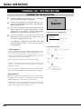
TURNING ON THE PROJECTOR
1
Complete peripheral connections (with a computer,
VCR, etc.) before turning on the projector.
2
Connect the projector’s AC power cord into an AC
outlet. The LAMP indicator lights RED, and the READY
indicator lights GREEN.
3
Press the POWER button on the top control or on the
remote control unit. The LAMP indicator dims, and the
cooling fans start to operate. The preparation display
appears on the screen and the countdown starts.
4
After the countdown, the input source that was
selected the last time and the Lamp mode status icon
(see page 41) appear on the screen.
30
The preparation display disappears after 30 seconds.
Selected Input Source and Lamp mode
Lamp mode status
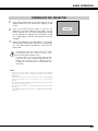
If the projector is locked with a PIN code, a PIN code
Input Dialog Box appears. Enter the PIN code as
instructed below.
PIN code Input Dialog Box
To Enter a PIN code
Pointer
Select a number by pressing the POINT LEFT/RIGHT button and
fix the number with the OK button. The number changes to “✳.”
If you fixed a wrong number, move the pointer to “Set” or
“Clear” once by pressing the POINT DOWN button, then return
to “PIN code.” Enter the correct number.
Repeat this step to complete entering a four-digit number.
When the four-digit number is fixed, the pointer automatically
moves to “Set.” Press the OK button so that you can start to
operate the projector.
If you entered a wrong PIN code, “PIN code” and the number
(✳✳✳✳) turn red and disappear. Enter a PIN code all over again.
What is PIN code?
PIN (Personal Identification Number) code is a security code that
allows the person who knows it to operate the projector. Setting
a PIN code prevents unauthorized use of the projector.
A PIN code consists of a four-digit number. Refer to the PIN code
lock function in the SETTING Menu on page 43 for locking
operation of the projector with your PIN code.
20
After the OK icon
disappears, you can
operate the projector.
BASIC OPERATION
TURNING OFF THE PROJECTOR
1
Press the POWER button on the top control or on the
remote control unit, and “Power off?” appears on the
screen.
2
Press the POWER button again to turn off the
projector. The LAMP indicator lights bright and the
READY indicator turns off. After the projector is turned
off, the cooling fans operate (for 90 seconds). During
this “cooling down” period, the projector cannot be
turned on.
3
“Power off?” disappears after 4 seconds.
When the projector has cooled down, the READY
indicator lights GREEN again and you can turn projector
on. After cooling down completely, unplug the AC
power cord.
TO MAINTAIN THE LIFE OF LAMP, ONCE YOU TURN
THE PROJECTOR ON, WAIT AT LEAST FIVE
MINUTES BEFORE TURNING IT OFF.
DO NOT UNPLUG THE AC POWER CORD WHILE
COOLING FANS ARE RUNNING OR BEFORE THE
READY INDICATOR LIGHTS GREEN AGAIN.
OTHERWISE IT WILL RESULT IN SHORTENING THE
LAMP LIFE.
NOTE:
• The projector cannot be turned on during the cooling period with the READY
indicator turned off. You can turn it on again after the READY indicator becomes
GREEN again.
• When the On start function is “On,” this projector is turned on automatically by
connecting the AC power cord to an AC outlet. (See page 41 for the On start
function.)
• Continuous use may result in shortening the lamp life. Turn off the projector and rest
it for about an hour in every 24 hours.
• The running speed of cooling fans is changed according to the temperature inside
the projector.
• If the WARNING TEMP indicator blinks RED, see “WARNING TEMP INDICATOR”
on page 46.
21
BASIC OPERATION
ADJUSTING SCREEN
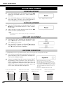
ZOOM ADJUSTMENT
1
Press the ZOOM button on the top control or ZOOM ▲/▼
buttons on the remote control unit. “Zoom” appears on
the screen.
2
Press the ZOOM ▲ button or POINT UP button to make
the image larger, and press the ZOOM ▼ button or
POINT DOWN button to make the image smaller.
“Zoom” disappears after 4 seconds.
FOCUS ADJUSTMENT
1
Press the FOCUS button on the top control or FOCUS
▲/▼ buttons on the remote control unit. “Focus” appears
on the screen.
2
Adjust the focus of image by pressing the FOCUS ▲/▼
buttons or POINT UP/DOWN buttons.
“Focus” disappears after 4 seconds.
NOTE:
• Focus adjustment may not function properly if the image is corrected by the
Keystone function.
LENS SHIFT ADJUSTMENT
1
Press the LENS SHIFT button on the top control or LENS
SHIFT ▲/▼ buttons on the remote control unit. “Lens
shift” appears on the screen.
2
Press the POINT UP button or LENS SHIFT ▲ button to
move the image up, press the POINT DOWN or LENS
SHIFT ▼ button to move the image down.
“Lens shift” disappears after 4 seconds.
KEYSTONE CORRECTION
If a projected picture has keystone distortion, correct the image with the Keystone function.
1
Press the KEYSTONE button on the remote control unit or
select Keystone in the SETTING Menu. (See page 38.)
The Keystone dialog box appears.
2
Correct keystone distortion by pressing the POINT
UP/DOWN/LEFT/RIGHT buttons. Press the POINT UP
button to reduce the upper part of the image; press the
POINT DOWN button to reduce the lower part. Press the
POINT LEFT button to reduce the left part; press the
POINT RIGHT button to reduce the right part.
Reduce the upper width
with POINT UP button.
22
Reduce the lower width
with POINT DOWN button.
• Arrows are white when no correction.
• Arrow(s) in the corrected direction turn(s) red.
• Arrow(s) disappear(s) at the maximum correction.
• If you press the KEYSTONE button on the remote
control unit once more while the Keystone dialog
box is being displayed, the Keystone function is
canceled.
• “Keystone” disappears after 10 seconds.
Reduce the left part with
POINT LEFT button.
Reduce the right part with
POINT RIGHT button.
BASIC OPERATION
PICTURE FREEZE FUNCTION
Press the FREEZE button on the remote control unit to freeze the picture on the screen. To cancel the FREEZE
function, press the FREEZE button again or press any other button.
NO SHOW FUNCTION
Press the NO SHOW button on the remote control unit to
black out the image. To restore to normal, press the NO
SHOW button again or press any other button.
“No show” disappears after 4 seconds.
P-TIMER FUNCTION
Press the P-TIMER button on the remote control unit. A Timer
display “00 : 00” appears on the screen and starts to count
time (00 : 00–59 : 59).
To stop the P-TIMER, press the P-TIMER button. Press the PTIMER button again to cancel the P-TIMER function.
SOUND ADJUSTMENT
DIRECT OPERATION
Indicates an approximate level of the volume.
Volume
Press the VOLUME (+/–) buttons on the top control or on the
remote control unit to adjust the volume. A Volume dialog box
appears on the screen for a few seconds.
Press the VOLUME (+) button to increase the volume; press
the VOLUME (–) button to decrease the volume.
Mute
Press the MUTE button on the remote control unit to turn off
the sound. To restore the sound to its previous level, press the
MUTE button again or press the VOLUME (+/–) buttons.
Press the MUTE button to set
the Mute function On or Off.
The Volume dialog box disappears after 4 seconds.
MENU OPERATION
1
2
Press the MENU button to display the On-Screen Menu.
Press the POINT LEFT/RIGHT buttons to move the red
frame pointer to the SOUND Menu icon.
SOUND MENU
Press the POINT UP/DOWN buttons to move the red
frame pointer to the desired item, and then press the OK
button.
Volume
To increase the volume, press the POINT RIGHT button; to decrease
the volume, press the POINT LEFT button.
SOUND Menu icon
Indicates an approximate
level of the volume.
Closes the SOUND Menu
Built-in SP.
Press the POINT LEFT/RIGHT buttons to switch the built-in speaker
On or Off.
Mute
Press the POINT LEFT/RIGHT buttons to turn off the sound. The
Dialog box display is changed to “On” and the sound is turned off. To
restore the sound to its previous level, press the POINT LEFT/RIGHT
buttons again.
23
COMPUTER INPUT
SELECTING INPUT SOURCE
DIRECT OPERATION
INPUT button
Select an INPUT source by pressing the INPUT button on
the top control or the INPUT 1, INPUT 2, or INPUT 3 buttons
on the remote control unit.
If the projector cannot reproduce proper image, select a
correct input source with the MENU OPERATION (see
below).
✽
Input 1
Input 2
Input 3
NOTE:
• Input 1 terminal is switchable and can be used as Computer Input or Monitor
Output.
✽ Input 1 is not displayed when the Input 1 is used as
Monitor out.
MENU OPERATION
WHEN SELECTING INPUT 1 (COMPUTER INPUT TERMINALS )
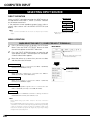
1
Press the MENU button to display the On-Screen
Menu. Press the POINT LEFT/RIGHT buttons to move
the red frame pointer to the INPUT Menu icon.
2
Press the POINT UP/DOWN buttons to move the red
arrow pointer to Input 1 and then press the OK button.
A Source Select Menu appears.
3
INPUT Menu icon
Move the pointer (red arrow) to Input
1 and press the OK button.
Move the pointer to a source that you want to select
and then press the OK button.
RGB(PC analog)
When your computer is connected to the INPUT 1 (ANALOG)
terminal, select RGB (PC analog).
RGB(Scart)
When scart video equipment is connected to the INPUT 1
(ANALOG) terminal, select RGB (Scart).
RGB(PC digital)
When your computer is connected to INPUT 1 (DIGITAL)
terminal, select RGB (PC digital).
RGB(AV HDCP)
If a HDCP-compatible signal source is connected to the
INPUT 1 (DIGITAL) terminal, select RGB (AV HDCP).
Monitor out
If the INPUT 1 ANALOG terminal is being used as a
MONITOR OUT terminal, select Monitor out.
NOTE:
• INPUT SOURCE changes if the INPUT 1 button on the remote control unit is
pressed.
• HDCP (High-bandwidth Digital Content Protection) is a system for protecting digital
entertainment content which is delivered by DVI (Digital Visual Interface) from being
copied. The specification of HDCP is decided and controlled by Digital Content
Protection, LLC. Should the specification be changed, this projector may not display
the digital content protected by HDCP.
24
INPUT MENU
Input 1
Source Select Menu
Move the pointer (red
arrow) to a source and press
the OK button.
COMPUTER INPUT
WHEN SELECTING INPUT 2 (5 BNC INPUT JACKS )
When connecting a computer output [5 BNC Type (Green,
Blue, Red, Horiz. Sync, and Vert. Sync.)] from a computer to
G, B, R, H/HV, and V jacks:
INPUT MENU
INPUT Menu icon
1
Press the MENU button to display the On-Screen
Menu. Press the POINT LEFT/RIGHT buttons to move
the red frame pointer to the INPUT Menu icon.
2
Press the POINT UP/DOWN buttons to move the red
arrow pointer to Input 2 and then press OK button. A
Source Select Menu appears.
3
Press the POINT UP/DOWN buttons and a red-arrow
icon appears. Move the arrow to “RGB,” and then
press the OK button.
Move the pointer (red arrow) to Input
2 and press the OK button.
Input 2
Source Select Menu
Move the pointer (red
arrow) to RGB and press the
OK button.
NOTE:
• INPUT SOURCE changes if the INPUT 2 button on the remote control unit is
pressed.
SELECTING COMPUTER SYSTEM
AUTOMATIC MULTI-SCAN SYSTEM
This projector automatically tunes to various types of computers based on VGA, SVGA, XGA, SXGA, SXGA+,
WXGA, or UXGA (refer to “COMPATIBLE COMPUTER SPECIFICATIONS” on pages 55–56). When Computer is
selected, this projector automatically detects the incoming signal and projects proper image without any
additional setting. (Some computers need to be set manually.)
The projector displays one of these: Auto, -----, Mode 1–10, or the system provided in the projector.
Auto
When the projector cannot recognize a connected
signal as PC system provided in this projector, the Auto
PC Adjustment function operates to adjust the projector
and “Auto” is displayed on the SYSTEM Menu icon.
When the image is not provided properly, a manual
adjustment is required. (See pages 27–28.)
-----
There is no signal input from the computer. Make sure
the connection of a computer and the projector is set
correctly. (See “TROUBLESHOOTING” on page 50.)
Mode 1
The User preset adjustment in MANUAL PC
ADJUSTMENT. The Adjusted data can be stored in the
Mode 1–10.
SVGA 1
PC systems provided in this projector. The projector
chooses proper system and displays it.
PC SYSTEM MENU
PC SYSTEM Menu icon
Displays system being selected.
✽ Mode 1 and SVGA 1 are examples.
SELECTING COMPUTER SYSTEM MANUALLY
This projector automatically selects PC system among those
provided in this projector, however, PC system can be also
selected manually.
1
Press the MENU button to display the On-Screen
Menu. Press the POINT LEFT/RIGHT buttons to move
the red frame pointer to the PC SYSTEM Menu icon.
2
Press the POINT UP/DOWN buttons to move the red
arrow pointer to the desired system, and then press
OK button.
PC SYSTEM MENU
PC SYSTEM Menu icon
Displays system being selected.
Systems in this dialog box can be
selected.
Custom Mode (1–10) set in PC
ADJUST Menu. (pp.27–28)
25
COMPUTER INPUT
PC ADJUSTMENT
AUTO PC ADJUSTMENT
Auto PC Adjustment function is provided to automatically adjust Fine sync, Total dots, Horizontal and Vertical
positions to conform to your computer. Auto PC Adjustment function can be operated as follows.
Auto PC adj.
1
Press the MENU button to display the On-Screen
Menu. Press the POINT LEFT/RIGHT buttons to move
the red frame pointer to the PC ADJUST Menu icon.
2
Press the POINT UP/DOWN buttons to move the red
frame pointer to the AUTO PC adj. icon and then press
the OK button.
This Auto PC Adjustment can be also executed by
pressing the AUTO PC ADJ. button on the top control
or on the remote control unit.
To store the adjusted parameters.
The system parameters from Auto PC Adjustment can be
memorized in this projector. Once the parameters are stored, the
setting can be done just by selecting Mode in PC SYSTEM Menu
(p.25). See MANUAL PC ADJUSTMENT on pages 27–28.
NOTE:
• Fine sync, Total dots, and Picture Positions of some computers can not be fully
adjusted with the Auto PC Adjustment function. When the image is not provided
properly with this function, manual adjustments are required. (See pages 27–28.)
• Auto PC Adjustment function cannot be operated in Digital Signal Input on the DVI
terminal and “480p,” “575p,” “480i,” “575i,” “720p (HDTV),” “1035i (HDTV),” or
“1080i (HDTV)” is selected on the PC SYSTEM Menu.
26
PC ADJUST MENU
PC ADJUST Menu icon
Move the red frame pointer to the Auto PC
adj. icon and press the OK button.
COMPUTER INPUT
MANUAL PC ADJUSTMENT
This projector can automatically tune to display signals from most personal computers currently distributed.
However, some computers employ special signal formats which may not be tuned by the Multi-Scan system of
this projector. If this happens, the projector cannot reproduce proper image and it may be recognized as a
flickering; non-synchronized; non-centered; or skewed picture.
Manual PC Adjustment of this projector enables you to precisely adjust several parameters to match with those
special signal formats. This projector has 10 independent memory areas to store those parameters manually
adjusted, which allows you to recall setting for a specific computer whenever you use it.
Note: The PC ADJUST Menu cannot be operated when the digital signal input on the DVI terminal is selected
on PC SYSTEM Menu. (p.25)
1
Press the MENU button to display the On-Screen
Menu. Press the POINT LEFT/RIGHT buttons to move
the red frame pointer to the PC ADJUST Menu icon.
2
Press the POINT UP/DOWN buttons to move the red
frame pointer to the desired item, and then press the
OK button. An Adjustment dialog box appears. Press
the POINT LEFT/RIGHT buttons to adjust the value.
PC ADJUST MENU
PC ADJUST Menu icon
Move the red frame pointer to an item and
press the OK button.
Fine sync
Eliminate a flicker from the display. Press the POINT LEFT/RIGHT
buttons to adjust the value (from 0 to 31).
Total dots
Shows status (Stored/Free)
of the selected Mode.
Adjust the number of total dots in one horizontal period. Press the
POINT LEFT/RIGHT buttons to adjust the number to match your PC
image.
Selected Mode
Position H
Press the POINT LEFT/RIGHT buttons to adjust the horizontal
picture position.
Position V
Press the POINT LEFT/RIGHT
buttons to adjust the value.
Press the OK button at this icon to
adjust “Clamp,” “Display area H,” or
“Display area V.”
Press the POINT LEFT/RIGHT buttons to adjust the vertical picture
position.
Current mode
Press the OK button to show H-sync freq. and V-sync freq. of the
connected computer.
Clamp
Current mode
Adjusts the clamp level. When the image has a dark bars, try this
adjustment.
Display area H
Adjusts the horizontal area displayed by this projector. Press the
POINT LEFT/RIGHT buttons to decrease/increase the value.
Display area V
Adjusts the vertical area displayed by this projector. Press the
POINT LEFT/RIGHT buttons to decrease/increase the value.
Press the OK button at
the Current mode icon
to show information of
the computer
connected.
Press the OK button at this icon to
display the previous items.
27
COMPUTER INPUT
Reset
To reset the adjusted parameters, select Reset and press the
OK button. A confirmation box appears. Select [Yes]. All the
adjustments return to their previous figures.
To store adjustment data.
This Mode has parameters being stored.
Mode free
To clear adjusted parameters previously set, move the red frame
pointer to the Mode free icon and then press the OK button.
Move the red arrow pointer to a Mode that you want to clear
and then press the OK button.
Store
To store the adjusted parameters, move the red frame pointer to
the Store icon and then press the OK button. Move the red
arrow pointer to any of the Mode 1 to 10 in which you want to
store the parameters and then press the OK button.
Quit
Close this dialog box.
Vacant
Shows the values of “Total
dots,” “Position H,” “Position
V,” “Display area H,” and
“Display area V.”
Exit the PC ADJUST Menu.
A confirmation box appears
and then select [Yes].
To clear adjustment data.
Close this dialog box.
A confirmation box appears
and then select [Yes].
28
COMPUTER INPUT
PICTURE IMAGE SELECT
IMAGE LEVEL SELECT
DIRECT OPERATION
Select an image level from among Standard, High contrast,
and Custom by pressing the IMAGE button on the top
control or on the remote control unit.
IMAGE button
Standard
Normal picture level preset on this projector.
High contrast
High contrast
Picture level with improved halftone for graphics.
Custom 1–10
User preset picture adjustment in the IMAGE ADJUST Menu.
(pp.35–37)
Standard
Custom 1
Custom 10
MENU OPERATION
1
Press the MENU button to display the On-Screen
Menu. Press the POINT LEFT/RIGHT buttons to move
the red frame pointer to the IMAGE SELECT Menu
icon.
2
Press the POINT UP/DOWN buttons to move the red
frame pointer to the desired level and then press the
OK button.
Standard
IMAGE SELECT MENU
IMAGE SELECT Menu icon
Move the red frame pointer to a level and
press the OK button.
Normal picture level preset on this projector.
High contrast
Picture level with improved halftone for graphics.
Custom 1–10
User preset picture adjustment in the IMAGE ADJUST Menu.
(pp.35–37)
29
COMPUTER INPUT
PICTURE SCREEN ADJUSTMENT
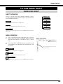
PICTURE SCREEN SELECT
This projector has a picture screen resize function, which enables you to display the desirable image size.
1
Press the MENU button to display the On-Screen
Menu. Press the POINT LEFT/RIGHT buttons to move
the red frame pointer to the SCREEN Menu icon.
2
Press the POINT UP/DOWN buttons and move the red
frame pointer to the desired function and then press
the OK button.
SCREEN MENU
SCREEN Menu icon
Move the red frame pointer to a function
and press the OK button.
Normal
Provides the image to fit the screen size.
True
Provides image in its original size.
Wide
Provides the image to fit the wide video aspect ratio (16:9) by
expanding the image width uniformly. This function can be used to
provide the squeezed video signal at 16:9.
Full
Provides the full screen image.
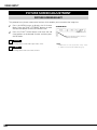
Digital zoom +
When the Digital zoom + is selected, the On-Screen Menu
disappears and “D. Zoom +” appears. Press the OK button to
expand the image size. Press the POINT UP/DOWN/LEFT/RIGHT
buttons to pan the image. The Panning function can work only
when the image is larger than the screen size.
The projected image can be also expanded by pressing the
D.ZOOM ▲ button on the remote control unit.
Digital zoom –
When the Digital zoom – is selected, the On-Screen Menu
disappears and “D. Zoom –” appears. Press the OK button to
compress the image size.
The projected image can be also compressed by pressing the
D.ZOOM ▼ button on the remote control unit.
To cancel the Digital Zoom +/– mode, press any button except
D.ZOOM ▲/▼, OK, POINT, and LASER buttons.
30
NOTE:
• True, Full, and Digital zoom +/– cannot be operated when
“480i,” “575i,” “480p,” or “575p is selected on the PC
SYSTEM Menu. (p.25)
• The Screen Menu cannot be operated when “720p (HDTV),”
“1035i (HDTV),” or “1080i (HDTV)” is selected on the PC
SYSTEM Menu. (p.25)
• This projector cannot display any resolution higher than 1600
x 1200. If your computer’s screen resolution is higher than
1600 x 1200, lower the resolution before connecting the
projector.
• The image data other than XGA (1024 x 768) is modified to
fit the screen size in initial mode.
• The Panning function may not operate properly if the
computer system prepared on the PC ADJUST Menu is used.
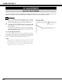
VIDEO INPUT
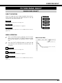
SELECTING INPUT SOURCE
DIRECT OPERATION
INPUT button
Select an INPUT source by pressing the INPUT button on
the top control or the INPUT 1, INPUT 2, or INPUT 3 buttons
on the remote control unit.
If the projector cannot reproduce proper image, select a
correct input source with the MENU OPERATION (see
below).
Input 1
Input 2
Input 3
✽ Input 1 is not displayed when the Input 1 is used as
Monitor out.
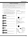
MENU OPERATION
WHEN SELECTING INPUT 2 (5 BNC INPUT JACKS )
When connecting to video equipment, select a type of Video
source in the Source Select Menu.
1
Press the MENU button to display the On-Screen
Menu. Press the POINT LEFT/RIGHT buttons to move
the red frame pointer to the INPUT Menu icon.
2
Press the POINT UP/DOWN buttons to move the red
arrow pointer to Input 2 and then press the OK button.
A Source Select Menu appears.
3
Move the pointer to a source that you want to select
and then press the OK button.
Video
INPUT MENU
INPUT Menu icon
Move the pointer (red arrow) to Input
2 and press the OK button.
Input 2
Source Select Menu
When the video input signal is connected to the
VIDEO jack, select Video.
Move the pointer (red arrow)
to Video or Y, Pb/Cb, Pr/Cr
and press the OK button.
Y, Pb/Cb, Pr/Cr When the video input signal is connected to the YPb/Cb-Pr/Cr jacks, select Y, Pb/Cb, Pr/Cr.
NOTE:
• INPUT SOURCE changes if the INPUT 2 button on the remote control unit is
pressed.
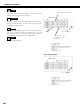
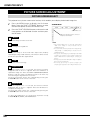
WHEN SELECTING INPUT 3 (AV TERMINALS )
When connecting to video equipment, select a type of Video
source in the Source Select (Video) Menu.
INPUT MENU
1
Press the MENU button to display the On-Screen
Menu. Press the POINT LEFT/RIGHT buttons to move
the red frame pointer to the INPUT Menu icon.
INPUT Menu icon
2
Press the POINT UP/DOWN buttons to move the red
arrow pointer to Input 3 and then press the OK button.
A Source Select Menu appears.
Move the pointer (red arrow) to Input
3 and press the OK button.
3
Move the pointer to a source that you want to select
and then press the OK button.
Input 3
Source Select Menu
Video
When the video input signal is connected to the
VIDEO jack, select Video.
Move the pointer (red
arrow) to a source and press
the OK button.
Y, Pb/Cb, Pr/Cr When the video input signal is connected to the YPb/Cb-Pr/Cr jacks, select Y, Pb/Cb, Pr/Cr.
S-Video
When the video input signal is connected to the SVIDEO jack, select S-Video.
NOTE:
• INPUT SOURCE changes if the INPUT 3 button on the remote control unit is
pressed.
31
VIDEO INPUT
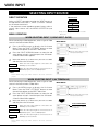
SELECTING VIDEO SYSTEM
1
Press the MENU button to display the On-Screen
Menu. Press the POINT LEFT/RIGHT buttons to move
the red frame pointer to the AV SYSTEM Menu icon.
2
Press the POINT UP/DOWN buttons to move the red
arrow pointer to the desired system and then press the
OK button.
VIDEO JACK OR S-VIDEO JACK
Auto
The projector automatically detects an incoming video system, and
adjusts itself to optimize its performance.
PAL / SECAM / NTSC / NTSC4.43 / PAL-M / PAL-N
If the projector cannot reproduce proper video image, select a
specific broadcast signal format from among PAL, SECAM, NTSC,
NTSC 4.43, PAL-M, and PAL-N.
AV SYSTEM MENU (VIDEO OR S-VIDEO)
AV SYSTEM Menu icon
This box indicates system being
selected.
Move the pointer (red arrow) to
system and press the OK button.
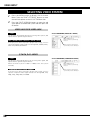
Y, Pb/Cb, Pr/Cr JACKS
Auto
The projector automatically detects an incoming video signal, and
adjusts itself to optimize its performance.
When the Video System is 1035i or 1080i, select the system
manually.
COMPONENT VIDEO SIGNAL FORMAT
If the projector cannot reproduce proper video image, select a
specific component video signal format from among 480i, 575i,
480p, 575p, 720p, 1035i, and 1080i.
32
AV SYSTEM MENU (COMPONENT VIDEO)
AV SYSTEM Menu icon
This box indicates system being
selected.
Move the pointer (red arrow) to
system and press the OK button.
VIDEO INPUT
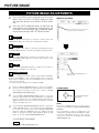
PICTURE IMAGE SELECT
IMAGE LEVEL SELECT
DIRECT OPERATION
Select an image level from among Standard, Cinema,
Custom by pressing the IMAGE button on the top control or
on the remote control unit.
Standard
Normal picture level preset on this projector.
IMAGE button
Standard
Cinema
Custom 1
Cinema
Picture level adjusted for picture with fine tone.
Custom 10
Custom 1–10
User preset picture adjustment in the IMAGE ADJUST Menu.
(pp.35–37)
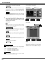
MENU OPERATION
1
Press the MENU button to display the On-Screen
Menu. Press the POINT LEFT/RIGHT buttons to move
the red frame pointer to the IMAGE SELECT Menu
icon.
2
Press the POINT UP/DOWN buttons to move the red
frame pointer to the desired level and then press the
OK button.
IMAGE SELECT MENU
IMAGE SELECT Menu icon
Move the red frame pointer to a level and
press the OK button.
Standard
Normal picture level preset on this projector.
Cinema
Picture level adjusted for picture with fine tone.
Custom 1–10
User preset picture adjustment in the IMAGE ADJUST Menu.
(pp.35–37)
33
VIDEO INPUT
PICTURE SCREEN ADJUSTMENT
PICTURE SCREEN SELECT
This projector has a picture screen resize function, which enables you to customize the image size.
1
Press the MENU button to display the On-Screen
Menu. Press the POINT LEFT/RIGHT buttons to move
the red frame pointer to the SCREEN Menu icon.
2
Press the POINT DOWN button and move the red
frame pointer to the desired function and then press
the OK button.
SCREEN MENU
SCREEN Menu icon
Move the red frame pointer to a function
and press the OK button.
Normal
Provides image at the normal video aspect ratio of 4:3.
Wide
Provides image at the wide screen ratio of 16:9.
34
NOTE:
• SCREEN Menu can not be operated when “720p,” “1035i,”
or “1080i” is selected in the AV SYSTEM Menu (p.32).
PICTURE IMAGE
PICTURE IMAGE ADJUSTMENTS
1
Press the MENU button to display the On-Screen
Menu. Press the POINT LEFT/RIGHT buttons to move
the red frame pointer to the IMAGE ADJUST Menu
icon.
2
Press the POINT UP/DOWN buttons to move the red
frame pointer to the desired item and then press the
OK button. The level of each item is displayed. Adjust
each level by pressing POINT LEFT/RIGHT buttons.
IMAGE ADJUST MENU
IMAGE ADJUST Menu icon
Move the red frame pointer to item to be
selected and then press OK button.
Contrast
Press the POINT LEFT button to decrease contrast; press the
POINT RIGHT button to increase the contrast (from 0 to 63).
Brightness
Press the POINT LEFT button to decrease the brightness; press
the POINT RIGHT button to increase the brightness (from 0 to 63).
Color
Press the POINT LEFT button decrease the intensity of the color;
press the POINT RIGHT button to increase the intensity of the
color (from 0 to 63).
Tint
Press the POINT LEFT/RIGHT buttons to adjust the tint value to
obtain proper color balance (from 0 to 63).
Color Management
The Color management function can be used to adjust the LEVEL,
PHASE, and GAMMA of the selected display colors (except for
black, white, and gray) on the screen and replace these colors with
other colors if required.
You can store up to eight (8) color management data.
1
Press the POINT UP/DOWN buttons to move the red frame
pointer to Color management, and then press the OK button.
The image being projected freezes, and the COLOR
MANAGEMENT POINTER appears.
2
Use the POINT UP/DOWN/LEFT/RIGHT buttons to move the
pointer to a spot where you want to adjust the color and then
press the OK button. The COLOR SELECTION window
appears, and the color in the center of the pointer is selected
and you can adjust the color.
3
Use the POINT UP/DOWN/LEFT/RIGHT buttons to adjust the
LEVEL and PHASE of the color, and then press the OK button
to confirm the setting. Then use the POINT UP/DOWN
buttons to adjust the GAMMA for the color and press the OK
button to accept the setting. After adjusting, press the OK
button to go to the COLOR MANAGEMENT LIST.
COLOR SELECTION MODE
Press the POINT LEFT/RIGHT buttons to
adjust the value.
POINTER MODE
COLOR MANAGEMENT
POINTER
NOTE:
Press the COLOR M. button on the remote
control unit to display the COLOR MANAGEMENT
POINTER.
If you would like to check or readjust the color
management setting that has already been made,
press the COLOR M. button on the remote
control unit once more to display the COLOR
MANAGEMENT LIST.
LIST
Go to the COLOR MANAGEMENT LIST.
35
PICTURE IMAGE
COLOR SELECTION MODE (continued)
COLOR M.
Return to the COLOR MANAGEMENT POINTER. (If you
press the MENU button on the top control or the remote
control unit, it returns to the COLOR MANAGEMENT
POINTER and you will need to reselect and readjust the
color.)
COLOR SELECTION MODE
Level and phase
adjustment palette.
Gamma
adjustment palette.
MENU
Return to the IMAGE ADJUST Menu. But any settings that
have been changed will not be stored. To store the changed
settings, be sure to select “LIST” and go to the COLOR
MANAGEMENT LIST.
4
In the COLOR MANAGEMENT LIST, the adjusted color
data are check marked. You can decide whether or not
to apply the adjusted color data in the list to the
projected image (see below).
LIST MODE
LIST
COLOR M.
MENU
LIST MODE
COLOR PALETTE
Clear the check mark if you do not want to apply the adjusted
color data; select the check mark and then press the OK
button. The check make disappears.
DEL
COLOR PALETTE
Return to the COLOR SELECTION mode so that you can
readjust the setting for the color in that line. (This option is
not available if the check mark is cleared.)
DEL
Select the DEL box if you want to delete the adjusted data.
Press the OK button and a confirmation box appears and then
select [Yes]
ALL DEL
Delete all the data in the list. Press the OK button and a
confirmation box appears and then select [Yes].
MENU
ALL DEL
MENU
COLOR M.
The same function as stated above.
COLOR M.
The same function as stated above.
Auto picture control
Press the POINT LEFT/RIGHT buttons to select the desired Auto
picture control position. The part where the image is dark is
emphasized. It is emphasized more strongly in order of Off, L1, L2.
Off . . . . Auto picture control OFF position.
L1 . . . . . Auto picture control LEVEL 1 position.
L2 . . . . . Auto picture control LEVEL 2 position.
Color temp.
Press either the POINT LEFT/RIGHT buttons to select the desired
Color temp. level (XLow, Low, Mid, or High).
36
NOTE:
If you press the COLOR M. button on the remote
control unit, the display returns to the normal
projection screen, but any settings that have been
changed will not be stored. To store the changed
settings, be sure to select “MENU” to return to
the IMAGE ADJUST Menu and store the settings.
PICTURE IMAGE
White balance (Red)
Press the POINT LEFT button to lighten red tone; press the POINT
RIGHT button to deepen red tone (from 0 to 63).
White balance (Green)
Press the POINT LEFT button to lighten green tone; press the
POINT RIGHT button to deepen green tone (from 0 to 63).
White balance (Blue)
Press the POINT LEFT button to lighten blue tone; press the POINT
RIGHT button to deepen blue tone (from 0 to 63).
Press the OK button at this icon to display
other items.
Sharpness
Press the POINT LEFT button to decrease the sharpness of the
image; press the POINT RIGHT button to increase the sharpness of
the image (from 0 to 31).
Gamma
Press the OK button at this icon to
display the previous items.
Press the POINT LEFT/RIGHT buttons to adjust the gamma value
to obtain better balance of contrast (from 0 to 15).
Noise reduction
Press the POINT LEFT/RIGHT
buttons to adjust the value.
Noise interference on the screen can be reduced. Press the POINT
LEFT/RIGHT buttons to change the noise reduction mode.
Off . . . . Noise reduction mode is “Off”
L1 . . . . . For lower reduction
L2 . . . . . For higher reduction
Progressive
An interlaced video signal can be displayed in progressive. Press
the POINT LEFT/RIGHT buttons to change the progressive scan
mode.
Off . . . . Progressive scan mode is “Off.”
On . . . . Progressive scan mode is “On.”
Film . . . Select for watching a film. With this function, the
projector reproduces pictures faithful to the original film
quality.
NOTE:
• The Film mode in the Progressive function cannot be selected when the video signal
format is 1080i or 1035i.
Reset
To reset the adjusted parameters, select Reset and press the OK
button. A confirmation box appears. Select [Yes]. All the
adjustments return to their previous figures.
Store
To store manually preset image, move the red frame pointer to the
Store icon and press the OK button. The Image Level Menu
appears. Move the red arrow pointer to the Custom 1 to 10 where
you want to set and then press the OK button.
Quit
Image Level Menu
Move the red frame pointer to any of
the Custom 1 to 10 where you want
to set and then press the OK button.
Store icon
Press the OK button at this icon
to store the adjustment.
Exit the IMAGE ADJUST Menu.
37
SETTING
SETTING MENU
This projector has Setting menu that allows you to set up the other various functions described as follows:
1
Press the MENU button to display the On-Screen
Menu. Press the POINT LEFT/RIGHT buttons to move
the red frame pointer to the Setting Menu icon.
2
Press the POINT DOWN button to move the red frame
pointer to the desired item that and then press the OK
button. The Setting dialog box appears.
SETTING MENU (LANGUAGE)
SETTING Menu icon
Set the red frame pointer
to the item and press the
OK button.
Language
The language used in the On-Screen Menu is available in English,
German, French, Italian, Spanish, Portuguese, Dutch, Swedish,
Russian, Chinese, Korean, or Japanese.
Keystone
This function corrects distortion of a projected image. Select either
Store or Reset with the POINT LEFT/RIGHT buttons, and then
press the OK button. The Keystone dialog box appears. Correct
keystone with the POINT UP/DOWN/LEFT/RIGHT buttons. (p.22)
Store . . . stores the keystone correction even if the AC power
cord is unplugged.
Reset . . resets the keystone correction when the AC power
cord is unplugged.
Background
Three background settings are available in this projector. Select one
of the following options when no input source is connected to the
projector or no input signal is coming from the connected
equipment.
Blue . . . blue colored background
User . . . the image you captured
Black . . . black colored background
Display
This function decides whether to display On-Screen Displays.
On . . . . . . . . . . . . shows all the On-Screen Display.
Count-down Off . . hide the Count-down Display.
Off . . . . . . . . . . . . hide the On-Screen Display except:
● On-Screen Menu
● “Power off?” (p.21)
● P-TIMER (p.23)
● ”Please wait....”
● Color management operation screen
(pp.35–36)
● “No signal” for Power management (p.40)
38
When pressing the OK button
at Language, the Language
Menu appears.
SETTING
Logo
Logo
This function allows you to customize the screen logo with Logo
select, Capture, and Logo PIN code lock functions.
Logo select
This function decides the start-up display as follows:
User . . . the image you captured
Default . the factory-set logo
Off . . . . count-down only
Capture
This function enables you to capture the image being projected
and use it for a starting-up display.
After capturing the projected image, go to the Logo select
function and set it to “User.” Then the captured image will be
displayed when turning on the projector the next time.
To capture the image, select [Yes]. To cancel the Capture
function, select [No].
NOTE:
• Before capturing an image, select Standard in the IMAGE SELECT Menu to
capture proper image. (See pages 29, 33.)
• A signal from a computer can be captured up to XGA (1024 x 768).
• Certain signals may not be captured properly.
• When capturing the image that has been adjusted by the Keystone function, the
adjusted data is automatically reset and the projector captures an image without
keystone correction.
• When starting to capture a new image, the previously stored image is cleared even
if you cancel the capturing.
• Once you exit the Logo Menu after setting the Logo lock to "On," you are required
to enter the PIN code every attempting to change the Logo setting.
Logo PIN code lock
This function prevents an unauthorized person from changing the
Logo setting.
Select [Yes] to
capture the
projected image.
Select [Yes] to stop
capturing.
Logo PIN Code Lock Dialog Box
Pointer
Quit
After a correct Logo PIN code is entered, the following dialog
box appears.
Off . . . . the Logo setting can be changed freely from the Logo
function.
On . . . . the Logo setting cannot be changed without a Logo
PIN code.
If you want to change the Logo PIN code lock setting, enter a
Logo PIN code by following the steps below. The initial Logo PIN
code is set to “4321” at the factory.
To Enter a Logo PIN code
Select a number by pressing the POINT LEFT/RIGHT buttons and
fix the number with the OK button. The number changes to “✳.”
If you fixed a wrong number, move the pointer to “Set” or
“Clear” once by pressing the POINT DOWN button, then return
to “Logo PIN code.” Enter the correct number.
Repeat this step to complete entering a four-digit number.
When the four-digit number is fixed, the pointer automatically
moves to “Set.” Press the OK button so that you can change the
Logo PIN code lock setting.
If you entered a wrong Logo PIN code, “Logo PIN code” and the
number (✳✳✳✳) turn red and disappear. Enter a Logo PIN code all
over again.
Select On/Off by pressing the POINT LEFT/RIGHT buttons or
change the Logo PIN code.
To Change the Logo PIN code
Logo PIN code can be changed to your desired
four-digit number. Select “Logo PIN code change”
with the POINT DOWN button and press the OK
button. Set a new Logo PIN code. Be sure to
write down the new Logo PIN code and keep it at
hand.
NOTE:
If you forget your Logo PIN code and unable to change
it, the Logo PIN code can be reset to the factory default
setting (4321) according to the following procedures.
When you reset the Logo PIN code, the PIN code and
Key lock will be reset, as well.
1. Unplug the AC Power Cord from the AC outlet.
2. Hold down the OK button on the projector and
connect the AC Power Cord into the outlet again.
Keep holding down the OK button until the POWER
indicator lights. The Logo PIN code returns to the
factory default setting while the Logo PIN code lock
state will remain the same as the previous set state.
39
SETTING
Ceiling
Ceiling
When this function is “On,” the picture is top/bottom and left/right
reversed. This function is used to project the image from a ceilingmounted projector.
Rear
When this function is “On,” the picture is left/right reversed. This
function is used to project the image to a rear projection screen.
Rear
Anamorphic
When this function is “On,” the screen image is forcibly changed
to the 4:3 image, even if the input signal is HDTV.
Simple menu
When this function is “On,” the value adjustment bar in the picture
IMAGE ADJUSTMENT Menu is displayed on the bottom left of the
screen.
Menu position
This function is used to adjust the On-Screen Menu display
position. When the OK button is pressed, the adjustment screen is
displayed (arrows appear). Use the POINT UP/DOWN/ LEFT/RIGHT
button(s) to adjust the position. After making the adjustment, press
the OK button to return to the Menu screen.
Power management
Power management
For reducing power consumption as well as maintaining the lamp
life, the Power management function turns off the projection lamp
when the projector is not used for a certain period.
If the input signal is interrupted and no button is pressed for more
than 30 seconds, the timer display with “No signal” appears on the
screen to start the countdown. The countdown time can be set
between 1 and 30 minutes.
Select one of the following operations:
Ready . . . . . When the lamp has been fully cooled down, the
READY indicator starts blinking. In this condition,
the projection lamp is turned on if the input signal is
reconnected or any button on the top control or
remote control unit is pressed.
Shutdown . . When the lamp has been fully cooled down, the
power is turned off.
Off . . . . . . . The Power management function is off.
40
Time left until lamp off
Press the OK button at Power
management and this box appears.
Choose one of three settings with
the POINT LEFT/RIGHT buttons,
and go to the timer with the POINT
DOWN button and set time with
the POINT LEFT/RIGHT buttons.
SETTING
On start
When this function is “On,” the projector is automatically turned
on just by connecting the AC power cord to an AC outlet.
NOTE:
• Be sure to turn the projector off properly (see “TURNING OFF THE PROJECTOR” on
page 21). If the projector is turned off in the incorrect sequence, such as unplugging
the AC power cord before completing the cool-down etc., the On start function does
not operate properly.
Lamp mode
This function allows you to change the brightness of the screen.
Auto mode . . . . . brightness according to the input signal.
Normal mode . . . normal brightness.
Silent mode . . . . . lower brightness reduces the lamp power
consumption and extends the lamp life.
Remote control
Remote control
The eight different remote control codes (Code 1–8) are assigned
to this projector: the factory-set, initial code (Code 1) and the other
seven codes (Code 2 to Code 8). This switching function prevents
interference from other remote controls when several projectors or
video equipment next to each other are operated at the same time.
For example, when operating the projector in “Code 7,” the code
for both the projector and the remote control unit must be
switched to “Code 7.”
To change the code of the projector:
Select from Code 1 to Code 8 in the SETTING Menu.
To change the code of the remote control unit:
Set the DIP switches 1–3 inside the battery compartment of the
remote control unit. (See page 15.)
When pressing the OK button at
Remote control, the Remote control
code menu appears.
41
SETTING
USB
This Projector has a USB port for interactive operation between the
projector and computers. Set the mode by following the steps
below.
Wireless Mouse mode
Select “
” when controlling a computer with the remote control
unit of this projector.
Projector mode:
“
” Not used.
Security
Security
Key lock
This function locks operation of the top control and remote
control unit. It helps to prevent operation by an unauthorized
person.
. . . . unlocked.
. . . . locks operation of the top control.
To unlock, use the remote control unit.
. . . . locks operation of the remote control unit.
To unlock, use the top control.
If the top control accidentally becomes locked and you do not
have the remote control unit nearby, unplug the AC power
cord from the AC outlet, and then hold down the OK button
and reinsert the AC power cord. This will cancel the top
control lock. Logo PIN code and PIN code will also be
cancelled.
42
Key lock
Select Key lock and
this box appears.
Choose one of the
alternatives with the
POINT UP/DOWN
buttons and select
[Yes] to activate it.
SETTING
PIN code lock
PIN code lock
This function prevents the projector from being operated by an
unauthorized person and provides the following settings for
security options.
Off . . . . the projector is not locked with the PIN code.
On1 . . . requires to enter the PIN code every time turning on
the projector.
On2 . . . requires to enter the PIN code to operate the projector
once the power cord is disconnected; as long as the
AC power cord is connected, the projector can be
operated without a PIN code.
When the projector is
locked with the PIN
code, the PIN code
lock mark appears on
the menu bar.
Whenever you change the PIN Code Lock setting or the PIN code
(the four-digit number), you are required to enter the PIN code.
“1234” is set as the initial PIN code at the factory.
To Enter a Logo PIN code
Select a number by pressing the POINT LEFT/RIGHT buttons and
fix the number with the OK button. The number changes to “✳.”
If you fixed a wrong number, move the pointer to “Set” or
“Clear” once by pressing the POINT DOWN button, then return
to “PIN code.” Enter the correct number.
Repeat this step to complete entering a four-digit number.
Entering a PIN code
Pointer
Quit
When the four-digit number is fixed, the pointer automatically
moves to “Set.” Press the OK button so that you can change the
PIN code lock settings.
The input numbers
change to “✳” for
security.
If you entered a wrong PIN code, “PIN code” and the number
(✳✳✳✳) turn red and disappear. Enter a Logo PIN code all over
again.
To Change the PIN Code Lock setting
When the pointer
automatically
moves to “Set,”
press the OK
button.
Select “Off,” “On1,” or “On2” with the POINT LEFT/RIGHT
buttons and then go to “Quit” with the POINT DOWN button.
Press the OK button to close the dialog box.
To Change the PIN Code
The PIN code can be changed to your desired four-digit number.
Select “PIN code change” with the POINT DOWN button, and
press the OK button. A New PIN code input dialog box appears.
Select a number with the POINT LEFT/RIGHT buttons and fix the
number with the OK button. Repeat it to complete entering a
four-digit number. When the four-digit number is fixed, the
pointer automatically moves to “Set.” Then press the OK button.
Be sure to write down the new Logo PIN code and keep it at
hand.
NOTE:
If you forget your PIN code and unable to change it, the PIN code can be
reset to the factory default setting (1234) according to the following
procedures.
When you reset the PIN code, the Logo PIN code and Key lock will be
reset, as well.
1. Unplug the AC Power Cord from the AC outlet.
2. Hold down the OK button on the projector and connect the AC Power
Cord into the outlet again. Keep holding down the OK button until the
POWER indicator lights. The PIN code returns to the factory default
setting while the PIN code lock state will remain the same as the
previous set state.
Changing the PIN code lock setting
Select a desired
setting with the
POINT LEFT/RIGHT
buttons.
Change the PIN code
Select PIN code
change and press
the OK button. The
New PIN code input
dialog box appears.
The input numbers
are being displayed
for confirmation.
43
SETTING
Lamp counter
Factory default
This function is used to reset the Lamp replacement counter.
When replacing the projection lamp, reset the Lamp replacement
counter with this function. See page 49 for operation.
Factory default
Select Factory default and this box
appears. Select [Yes], and the next
box appears.
This function returns all setting values except for the User logo,
Key lock, PIN code lock, Logo PIN code lock, and the Lamp counter
to the factory default settings.
Quit
Exit the SETTING Menu.
44
Select [Yes] to
activate it.
APPENDIX
WIRELESS MOUSE
Remote control unit is not only able to operate this projector but also functions as a wireless mouse for most
personal computers. The MOUSE POINTER, DRAG ON/OFF button, and two CLICK buttons are used for
wireless mouse operation.
The Wireless mouse function is available only when the PC mouse pointer is displayed on the screen.
INSTALLATION
To use the remote control unit as a wireless mouse for a computer, installation of a mouse driver (not supplied)
is required. Make sure that the mouse driver is properly installed on your computer and that the mouse port (or
USB port) of the computer is activated.
1
Connect the mouse port (or USB port) of your
computer to the CONTROL PORT (or USB connector)
of this projector with the Control cable (or USB cable).
(See pages 12–13 for connection.)
2
Turn on the projector first, and then turn your computer
on. If the computer is switched on first, the Wireless
mouse function may not work properly.
Note:When your computer has no mouse
port, connect the Serial port of your
computer to the Control port of the
projector with the Control cable for Serial
port (supplied).
OPERATING WIRELESS MOUSE
When controlling the PC mouse pointer, use the MOUSE POINTER, DRAG ON/OFF button, LEFT CLICK button,
and RIGHT CLICK button on the remote control unit.
MOUSE POINTER
Used to move the PC mouse pointer. The pointer moves to
the direction you are pressing.
DRAG ON
INDICATOR
LEFT CLICK button
This button has the same function as the left button in a PC
mouse. To drag a selected screen object, hold down this
button and press the MOUSE POINTER.
RIGHT CLICK button
This button has the same function as the right button in a PC
mouse.
DRAG ON/OFF button
Use this button and the MOUSE POINTER to drag a
selected screen object. Press and release the DRAG
ON/OFF button, then the DRAG ON INDICATOR lights
green and the remote control unit is in Drag mode. Use the
MOUSE POINTER to drag an screen object. Press and
release the DRAG ON/OFF button again or press any other
button to drop the object.
DRAG ON/OFF
button
MOUSE POINTER
(Moves the pointer)
LEFT CLICK button
(left button of the mouse)
RIGHT CLICK button
(right button of the mouse)
45
APPENDIX
MAINTENANCE
WARNING TEMP. INDICATOR
The Warning Temp. indicator blinks red to let you know the internal
temperature of the projector exceeds a normal level. If the temperature
goes up further, the projector will be turned off automatically and the
Ready indicator goes out. (The Warning Temp. indicator continues
blinking.) After the cooling-off period, the Ready indicator lights on again
and the projector can be turned on by pressing the POWER button on the
top control or the remote control unit. When you turn on the projector,
the Warning Temp. indicator goes out.
TOP CONTROL
Warning Temp.
Indicator
Ready
Indicator
If the Warning Temp. indicator is still blinking, check the following
matters:
– The ventilation slots of the projector may be blocked. In such a case,
reposition the projector so that the ventilation slots are not obstructed.
– The air filters may be clogged with dust particles. Clean them by
following the section “AIR FILTER CARE AND CLEANING” on the next
page.
– If the WARNING TEMP. indicator remains on after performing above
checks, the cooling fans or internal circuits may be malfunctioning.
Contact the service station.
When both of the Warning Temp. and Ready indicators are blinking:
When the projector detects an internal problem, it shuts down automatically and both the Warning Temp. and
Ready indicators start blinking. In this condition, the projector cannot be turned on even if you press the
POWER button on the top control or remote control unit. If this happens, unplug and reconnect the AC power
cord, and then turn on the projector again to check the operation. If the projector shuts down again or cannot to
be turned on, internal checking and repair is required. Unplug the AC power cord and contact the service
station.
46
APPENDIX
AIR FILTERS CARE AND CLEANING
Air filters help prevent dust from accumulating on the optical elements inside the projector. To whatever extent
the air filters become clogged with dust particles, the cooling fans’ effectiveness is reduced, which may result
in an internal heat build-up and adversely affect the life of the projector. Therefore, for appropriate care and use
of the projector, regular cleaning of the air filters is necessary.
How often the air filters should be cleaned really depends upon the environment in which the projector is being
operated. As a rough guide, under a normally clean operating environment, the air filters should be cleaned
approximately every 200 hours of use. However, if the projector is being operated in a somewhat dusty or
smoky environment, the air filters should be cleaned more often; for consistently good projector operation and
performance, timely cleaning of the air filters is a very important factor. When appropriate, clean the air filters
following the steps below.
1
Turn off the projector and unplug the AC power cord
from an AC outlet.
2
Turn over projector and remove the air filters by pulling
the latches upward.
3
Clean the air filters with a brush or rinse them softly.
When rinsing the air filters, dry them well.
4
Replace the air filters properly. Make sure that the air
filters are fully inserted to the projector.
CAUTION
Do not operate the projector with the air filters
removed. Dust may accumulate on the LCD Panel and
projection mirror degrading the picture quality. Do not
put anything into the air intake vents. It may result in
malfunction of the projector.
A
B
AIR FILTERS
Pull up and remove.
NOTE: If the dust cannot be removed by
cleaning, it is probably time to replace
the air filters with new ones. Please
consult your dealer.
RECOMMENDATION
We recommend avoiding dusty/smoky environments when operating the projector. Usage in these
environments may cause a poor image quality.
When using the projector under dusty or smoky conditions, dust may accumulate on a lens, liquid crystal
panels, or optical elements inside the projector. Such condition may degrade the quality of the projected
image. When the symptoms above are noticed, contact your authorized dealer or service station for proper
cleaning.
CLEANING PROJECTION LENS
Follow these steps to clean the projection lens:
1
Turn off the projector and unplug the AC power cord from an AC outlet.
2
Apply a non-abrasive camera lens cleaner to a dry soft cleaning cloth. Avoid using an excessive amount of
cleaner. Abrasive cleaners, solvents ,or other harsh chemicals might scratch the surface of the lens.
3
Gently wipe with the cleaning cloth over the projection lens.
4
When the projector is not in use, put the lens cap.
47
APPENDIX
LAMP REPLACEMENT
When the projection lamp of this projector reaches its end
of life, the LAMP REPLACE indicator lights orange. If this
indicator lights orange, replace the projection lamp with a
new one promptly.
TOP CONTROL
This indicator lights orange
when the projection lamp
reaches its end of life.
Replace the projection lamp
with a new one promptly.
CAUTION
CAUTION
Allow the projector to cool for at least 45 minutes
before you open the lamp cover. The inside of the
projector can become very hot.
For continued safety, replace with a lamp
assembly of the same type.
Do not drop the lamp assembly or touch a glass
bulb! The glass can shatter and may cause injury.
Follow these steps to replace lamp assembly.
1
Turn off the projector and unplug the AC power cord.
Allow the projector to cool for at least 45 minutes.
2
Loosen the two (2) screws with a screwdriver and
open the lamp cover.
3
Loosen the two (2) screws with a screwdriver and pull
out the lamp assembly by using the built in handle.
4
Replace the lamp assembly with a new one and tighten
the two (2) screws. Make sure that the lamp assembly
is set properly. Put back the lamp cover and tighten the
two (2) screws.
5
Connect the AC power cord to the projector and turn
on the projector.
6
Reset the Lamp replacement counter (refer to”LAMP
REPLACE COUNTER” on the next page).
LAMP COVER
LAMP
ASSEMBLY
HANDLE
NOTE:
• Do not reset the Lamp replacement counter when the projection lamp is not
replaced.
ORDER REPLACEMENT LAMP
Replacement lamp can be ordered through your dealer. When ordering a projection lamp, give the following
information to the dealer.
●
Model No. of your projector
● Replacement Lamp Type No.
:
:
LV-7575
LV-LP28
(610 328 7362)
48
APPENDIX
LAMP REPLACE COUNTER
Be sure to reset the Lamp replacement counter after the lamp assembly is replaced. When the Lamp
replacement counter is reset, the LAMP REPLACE indicator stops lighting.
1
Turn the projector on and press the MENU button to
display the On-Screen Menu. Press the POINT
LEFT/RIGHT buttons to move the red frame pointer to
the SETTING Menu icon
2
Press the POINT UP/DOWN buttons to move the red
frame pointer to Lamp counter and then press the OK
button. The next box appears.
3
Press the POINT UP/DOWN buttons to select Reset
and then press the OK button. The “Lamp replacement
counter reset?” appears. Move the pointer to [Yes] and
then press the OK button.
4
Another confirmation dialog box appears and select
[Yes] to reset the Lamp replacement counter.
Lamp counter
Select Lamp counter and this box
appears. Select [Reset], and the
next box appears.
Select [Yes], and then another
confirmation box appears.
NOTE:
• Do not reset the Lamp replacement counter until after the projection lamp is
replaced.
Select [Yes] again
to reset the lamp
counter.
LAMP HANDLING PRECAUTIONS
This projector uses a high-pressure lamp which must be handled carefully and properly. Improper
handling may result in accidents, injury, or create a fire hazard.
● Lamp lifetime may differ from lamp to lamp and according to the environment of use. There is no
guarantee of the same lifetime for each lamp. Some lamps may fail or terminate their lifetime in a
shorter period of time than other similar lamps.
● If the projector indicates that the lamp should be replaced, i.e., if the LAMP REPLACE indicator lights
up, replace the lamp with a new one IMMEDIATELY after the projector has cooled down. (Follow
carefully the instructions in the LAMP REPLACEMENT section of this manual.) Continuous use of the
lamp with the LAMP REPLACE indicator lighted may increase the risk of lamp explosion.
● Lamp may explode as a result of vibration, shock or degradation as a result of hours of use as its
lifetime draws to an end. Risk of explosion may differ according to the environment or conditions in
which the projector and lamp are being used.
IF A LAMP EXPLODES, THE FOLLOWING SAFETY PRECAUTIONS SHOULD BE TAKEN.
If a lamp explodes, disconnect the projector’s AC plug from the AC outlet immediately and open the
window or door for ventilation. Contact an authorized service station for a checkup of the unit and
replacement of the lamp. Additionally, check carefully to ensure that there are no broken shards or pieces
of glass around the projector or coming out from the cooling air circulation holes. Any broken shards
found should be cleaned up carefully. No one should check the inside of the projector except those who
are authorized trained technicians and who are familiar with projector service. Inappropriate attempts to
service the unit by anyone, especially those who are not appropriately trained to do so, may result in an
accident or injury caused by pieces of broken glass.
49
APPENDIX
TROUBLESHOOTING
Before calling your dealer or service center for assistance, check the items below once again.
1. Make sure you have connected the projector to your computer or video equipment as described in
“CONNECTING PROJECTOR” on pages 12–14.
2. Check the cable connection. Make sure that all computers, video equipment, and power cords are properly
connected.
3. Make sure that all power is switched on.
4. If the projector still does not produce an image, restart your computer.
5. If an image still does not appear, disconnect the projector from your computer and check your computer
monitor’s display. A problem may be noticed with your graphics controller rather than with the projector.
(When you reconnect the projector, be sure to turn the computer and monitor off before you turn on the
projector. Turn on equipment in the order of the projector and computer.)
6. If a problem still persists, check the following solutions.
Problem:
No power.
Try these Solutions
● Plug the power cord of the projector into an AC outlet.
● Make sure the READY indicator lights.
● Wait 90 seconds after the projector is turned off to restart the projector.
NOTE: After pressing the POWER button to “OFF,” make sure the projector works as
follows:
1. LAMP indicator lights bright and the READY indicator turns off.
2. After 90 seconds, the READY indicator lights green again and the projector may
be turned on by pressing the POWER button.
● Check the WARNING TEMP. and READY indicators. If both indicators blink, the projector
cannot be turned on.
(See “TURNING ON/OFF PROJECTOR” on pages 20–21.)
● Check the projection lamp. (See page 48.)
Image is out of focus.
● Adjust the focus of the projector.
● Make sure the projection screen is at least 1.4 m (4.6’) away from the projector.
● Check the projection lens to see if it needs cleaning.
NOTE: Moving the projector from a cool to a warm place may result in moisture
condensation on the projection lens. If this happens, leave the projector off and
wait until condensation evaporates.
Picture is left/right
reversed.
● Check the Ceiling/Rear function. (See page 40.)
Picture is
top/bottom
reversed.
● Check the Ceiling function. (See page 40.)
Some displays are
not seen during
operations.
● Check the Display function.(See page 38.)
No image.
● Check the connection between your computer or video equipment and the projector.
● When turning the projector on, it takes about 30 seconds to display the image.
● Check the system you selected is corresponding to your computer or video equipment.
● Make sure the temperature is not out of specified operating temperature (5˚C–35˚C
[41˚F–95˚F]).
No sound.
50
● Check the audio cable connection from an audio input source.
● Adjust the audio source.
● Press the VOLUME (+) button.
● Press the MUTE button.
APPENDIX
Problem:
Try these Solutions
Remote control unit
does not work.
● Check the batteries.
● Check if the ALL-OFF switch on the remote control unit is set to “ON.”
● Make sure there is no obstruction in between the Infrared remote receiver of the
projector and the remote control unit.
● Make sure you are not too far from the projector when using the remote control unit.
Maximum operating range is 5 m (16.4’).
● Check the remote control code in the remote control unit. (See page 41.)
● Check if the remote control keys are locked. (See page 42.)
Wireless mouse
function does not
work.
● Check the cable connection between the projector and your computer.
● Check the mouse setting on your computer.
● Turn the projector on before turning on a computer.
WARNING:
High voltages are used to operate this projector. Do not attempt to open the cabinet.
If the problem still persists after following all operating instructions, contact the sales dealer where you
purchased the projector or the service center. Specify the model number and explain the difficulty. We will
advise you how to obtain service.
51
APPENDIX
MENU TREE
Computer Input/Video Input
Input
Input 1
Go to System (1)
RGB (PC analog)
RGB (Scart)
RGB (PC digital)
RGB (AV HDCP)
Monitor out
Input 2
Input 3
Video
Go to System (2)
Y, Pb/Cb, Pr/Cr
Go to System (3)
RGB
Go to System (1)
Video
Go to System (2)
Y, Pb/Cb, Pr/Cr
Go to System (3)
S-Video
Go to System (2)
Computer Input
System (1)
Image Select
Mode 1
Standard
Mode 2
High contrast
SVGA 1
Custom 1
SVGA 2
SVGA 3
Custom 10
✽ System displayed in the System Menu varies depending on the input signal.
PC Adjust
Screen
Auto PC adj.
Fine sync.
0–31
True
Total dots
Wide
Position H
Full
Position V
Digital zoom +
Current mode
Digital zoom -
Clamp
Display area - H
Display area - V
Reset
Yes/No
Mode free
Store
Mode 1
Mode 2
Mode 3
Mode 4
Mode 5
Mode 6
Mode 7
Mode 8
Mode 9
Mode 10
Quit
Quit
52
Normal
APPENDIX
Video Input
System (2)
Auto
PAL
SECAM
NTSC
NTSC 4.43
PAL-M
PAL-N
System (3)
Auto
1080i
1035i
720p
575p
480p
575i
480i
Image Select
Standard
Cinema
Custom 1
Custom 10
Screen
Normal
Wide
Computer Input/Vide Input
Image Adjust
Contrast
0–63
Brightness
0–63
Color
0–63
Tint
0–63
Color management
Color
Gamma
List
All Del
Color M.
Menu
Menu
Color M.
Auto picture control
Off/L1/L2
Color temp.
High
Yes/No
Mid
Low
XLow
Red
0–63
Green
0–63
Blue
0–63
Sharpness
0–31
Gamma
0–15
Noise reduction
Off/L1/L2
Progressive
Off/On/Film
Reset
Yes/No
Store
Custom 1
Custom 10
Quit
Quit
Sound
Volume
0–63
Built-in SP.
On/Off
Mute
On/Off
Quit
53
APPENDIX
Computer Input/Vide Input
Setting
Language
English
German
French
Italian
Spanish
Portuguese
Dutch
Swedish
Russian
Chinese
Korean
Japanese
Quit
Keystone
Store/Reset
Background
Blue/User/Black
Display
Off/Countdown Off/On
Logo
Logo select
User
Default
Capture
Off
Logo PIN code lock
Logo PIN code
Quit
Ceiling
On/Off
Rear
On/Off
Anamorphic
On/Off
Simple menu
On/Off
Set
Logo PIN code lock
Clear
Logo PIN code change
Quit
Quit
On/Off
Menu position
Power management
Off
Ready
Shut down
1–30 Min.
Quit
On start
On/Off
Lamp mode
Auto/Normal/Silent
Remote Control
Code 1
Code 8
Quit
USB
Mouse
Projector
Security
Key lock
Off
Projector
Remote Control
Quit
PIN code lock
Lamp counter
Reset
Factory default
Yes/No
Quit
54
PIN code
Set
PIN code lock
Clear
PIN code change
Quit
Quit
Yes/No
Off/On1/On2
APPENDIX
COMPATIBLE COMPUTER SPECIFICATIONS
Basically this projector can accept a signal from all computers with V-, H-Frequency mentioned below, and less
than 140 MHz of Dot Clock.
ON-SCREEN
DISPLAY
VGA 1
VGA 2
VGA 3
VGA 4
VGA 5
VGA 6
VGA 7
MAC LC13
MAC 13
480i
575i
480p
575p
SVGA 1
SVGA 2
SVGA 3
SVGA 4
SVGA 5
SVGA 6
SVGA 7
SVGA 8
SVGA 9
SVGA 10
SVGA 11
MAC 16
XGA 1
XGA 2
XGA 3
XGA 4
XGA 5
XGA 6
XGA 7
XGA 8
XGA 9
XGA 10
XGA 11
XGA 12
XGA 13
XGA 14
XGA15
MAC 19
RESOLUTION
640 x 480
720 x 400
640 x 400
640 x 480
640 x 480
640 x 480
640 x 480
640 x 480
640 x 480
––––––––
(Interlace)
––––––––
(Interlace)
––––––––
(Progressive)
––––––––
(Progressive)
800 x 600
800 x 600
800 x 600
800 x 600
800 x 600
800 x 600
800 x 600
800 x 600
800 x 600
800 x 600
800 x 600
832 x 624
1024 x 768
1024 x 768
1024 x 768
1024 x 768
1024 x 768
1024 x 768
1024 x 768
1024 x 768
1024 x 768
(Interlace)
1024 x 768
1024 x 768
1024 x 768
(Interlace)
1024 x 768
1024 x 768
1024 x 768
1024 x 768
H-Freq.
(kHz)
V-Freq.
(Hz)
ON-SCREEN
DISPLAY
31.47
31.47
31.47
37.86
37.86
37.50
43.269
34.97
35.00
15.734
15.625
31.47
31.25
35.156
37.88
46.875
53.674
48.08
37.90
34.50
38.00
38.60
32.70
38.00
49.72
48.36
68.677
60.023
56.476
60.31
48.50
44.00
63.48
36.00
62.04
61.00
35.522
46.90
47.00
58.03
60.24
59.88
70.09
70.09
74.38
72.81
75.00
85.00
66.60
66.67
60.00
50.00
59.88
50.00
56.25
60.32
75.00
85.06
72.19
61.03
55.38
60.51
60.31
51.09
60.51
74.55
60.00
84.997
75.03
70.07
74.92
60.02
54.58
79.35
87.17
77.07
75.70
86.96
58.20
58.30
72.00
75.08
MAC 21
SXGA 1
SXGA 2
SXGA 3
SXGA 4
SXGA 5
SXGA 6
SXGA 7
SXGA 8
SXGA 9
SXGA 10
SXGA 11
SXGA 12
SXGA 13
SXGA 14
SXGA 15
SXGA 16
SXGA 17
SXGA 18
SXGA 19
SXGA 20
SXGA+ 1
SXGA+ 2
SXGA+ 3
MAC
MAC
WXGA 1
WXGA 2
WXGA 3
WXGA 4
UXGA1
UXGA2
UXGA3
UXGA4
720p
720p
1035i
1080i
1080i
RESOLUTION
1152 x 870
1152 x 864
1280 x 1024
1280 x 1024
1280 x 1024
1280 x 1024
1280 x 1024
1280 x 1024
1280 x 1024
1280 x 1024
1280 x 960
1152 x 900
1152 x 900
1280 x 1024
(Interlace)
1280 x 1024
(Interlace)
1280 x 1024
1280 x 1024
1152 x 900
1280 x 1024
(Interlace)
1280 x 1024
1280 x 1024
1400 x 1050
1400 x 1050
1400 x 1050
1280 x 960
1280 x 1024
1366 x 768
1360 x 768
1376 x 768
1360 x 768
1600 x 1200
1600 x 1200
1600 x 1200
1600 x 1200
––––––––
(Progressive)
––––––––
(Progressive)
––––––––
(Interlace)
––––––––
(Interlace)
––––––––
(Interlace)
H-Freq.
(kHz)
V-Freq.
(Hz)
68.68
64.20
62.50
63.90
63.34
63.74
71.69
81.13
63.98
79.976
60.00
61.20
71.40
50.00
50.00
63.37
76.97
61.85
46.43
63.79
91.146
63.97
65.35
65.12
75.00
80.00
48.36
47.70
48.36
56.16
75.00
81.25
87.50
93.75
45.00
37.50
33.75
33.75
28.125
75.06
70.40
58.60
60.00
59.98
60.01
67.19
76.107
60.02
75.025
60.00
65.20
75.60
86.00
94.00
60.01
72.00
66.00
86.70
60.18
85.024
60.19
60.12
59.90
75.08
75.08
60.00
60.00
60.00
72.00
60.00
65.00
70.00
75.00
60.00
50.00
60.00
60.00
50.00
55
APPENDIX
When a input signal is digital from DVI terminal, refer to the chart below.
ON-SCREEN
DISPLAY
D-VGA
D-480p
D-575p
D-SVGA
D-XGA
D-WXGA1
D-WXGA2
D-WXGA3
D-WXGA5
✳ D-SXGA1
H-Freq.
(kHz)
V-Freq.
(Hz)
ON-SCREEN
DISPLAY
31.47
31.47
31.25
37.879
43.363
48.36
47.70
48.36
46.50
63.98
59.94
59.88
50.00
60.32
60.00
60.00
60.00
60.00
50.00
60.02
✳ D-SXGA2
✳ D-SXGA+ 1
D-720p
D-720p
D-1035i
D-1080i
D-1080i
1280 x 1024
1400 x 1050
D-1080psf/30
1920 x 1080
1920 x 1080
1920 x 1080
RESOLUTION
640 x 480
720 x 480
(Progressive)
768 x 575
(Progressive)
800 x 600
1024 x 768
1366 x 768
1360 x 768
1376 x 768
1368 x 768
1280 x 1024
D-1080psf/25
D-1080psf/24
RESOLUTION
1280 x 720
(Progressive)
1280 x 720
(Progressive)
1920 x 1035
(Interlace)
1920 x 1080
(Interlace)
1920 x 1080
(Interlace)
H-Freq.
(kHz)
V-Freq.
(Hz)
60.276
63.97
45.00
37.50
33.75
33.75
28.125
33.75
28.125
27.00
58.069
60.19
60.00
50.00
60.00
60.00
50.00
60.00
50.00
48.00
✳ Depending on the condition of signals and the type and length of cables, these signals may not be properly viewed.
NOTE: Specifications are subject to change without notice.
INDICATORS AND PROJECTOR CONDITION
Check the indicators for projector condition.
Indicators
LAMP
REPLACE
WARNING
TEMP.
orange
red
READY
LAMP
green
red
Projector Condition
The projector is OFF. (The AC power cord is unplugged.)
✽
The projector is ready to be turned on with the POWER
button.
✽
The projector is operating normally.
✽
The Warning Temp. indicator blinks red to let you know the
internal temperature of the projector exceeds a normal level.
If the temperature goes up further, the projector will be
turned off automatically and the Ready indicator goes out.
When the projector is cooled down enough and the
temperature returns to normal, the READY indicator lights
green and the projector can be turned on again. (The
WARNING TEMP. indicator keeps blinking.) Check and clean
the air filters.
✽
The projector is cooled down enough and the temperature
returns to normal. When turning on the projector, the
WARNING TEMP. indicator stops blinking. Check and clean
the air filters.
• • • on
56
• • • blinking
• • • dim
• • • off
APPENDIX
Indicators
LAMP
REPLACE
orange
WARNING
TEMP.
red
READY
LAMP
green
red
Projector Condition
The projector is in cooling mode. It cannot be turned on until
the READY indicator lights green.
✽
The projector detects an abnormal condition and cannot be
turned on. Unplug the AC power cord and plug it again to turn
on the projector. If the projector is turned off again,
disconnect the AC power cord and contact the dealer or the
service center for service and checkup. Do not leave the
projector on. It may cause electric shock or a fire hazard.
✽
The projector is in the Power management mode.
✽
The temperature inside the projector is abnormally high.
The lamp cannot light up. (The projector is preparing for standby or the projection lamp is in cooling mode. The projector
cannot be turned on until the cooling process is completed.)
The lamp cannot light up. (The lamp has been cooled down
enough and the projector is in stand-by mode and ready to be
turned on with the POWER button.)
The projection lamp reaches its end of life.
Replace the lamp and then reset the Lamp replacement
counter. The indicator is turned off.
✽
• • • on
• • • blinking
• • • dim
• • • off
*When the projection lamp reaches its end of life, the LAMP REPLACE indicator lights orange. When this indicator
lights orange, replace the projection lamp with a new one promptly. Reset the Lamp replacement counter after
replacing the lamp.
57
APPENDIX
TECHNICAL SPECIFICATIONS
Projector Type
Dimensions (W x H x D)
Net Weight
LCD Panel System
Panel Resolution
Number of Pixels
Color System
High Definition TV Signal
Scanning Frequency
Projection Lens
Throw distance
Motorized Lens Shift
Projection Image Size (Diagonal)
Horizontal Resolution
Projection Lamp
Input 1 Jacks
Multi-media Projector
Input 2 Jacks
BNC Type x 5 (G or VIDEO/Y, B or Cb/Pb, R or Cr/Pr, H/V, and V) and
Stereo Mini Type Jack (Audio)
Input 3 Jacks
RCA Type x 3 (VIDEO/Y, Cb/Pb and Cr/Pr), RCA Type x 2 (Audio R and L),
and DIN 4-pin (S-Video)
Other Jacks
DIN 8-pin (Control port), USB port (Series B receptacle), Wired Remote Jack ,
and Network Imager Connector
Built-in Speakers
Feet Adjustment
INT. SP. Stereo (R and L), 3 watt RMS (T.H.D. 10%)
Voltage and Power
Consumption
Operating Temperature
Storage Temperature
Remote Control Transmitter
AC 100–120 V (5.7 A Max. Ampere), 50/60 Hz (The U.S.A and Canada)
AC 200–240 V (2.7 A Max. Ampere), 50/60 Hz (Continental Europe)
Accessories
User’s Manual (CD-ROM)
Quick Start Guide
AC Power Cord
Wireless/Wired Remote Control Transmitter and Batteries
VGA Cable
USB Cable
Control Cable for Serial Port
Lens Cap
Lens Replacement And Installation Manual
PIN Code Label
Warranty Card
319.0 mm x 168.0 mm x 429.5 mm (12.6” x 6.61” x 16.8”)
8.7 kg (19.2 lbs)
1.3” TFT Active Matrix type, 3 panels
1024 x 768 dots
2,359,296 (1024 x 768 x 3 panels)
PAL, SECAM, NTSC, NTSC4.43, PAL-M, and PAL-N
480i, 480p, 575i, 575p, 720p, 1035i, and 1080i
H-sync. 15 kHz–100 kHz, V-sync. 48–100 Hz
F1.8–2.1 lens with f=48.4 mm–62.8 mm Motor zoom and focus
1.4 m (4.6’)–14.7 m (48.2’)
Up and Down (1:1 to 10:0)
Adjustable from 31” to 400”
800 TV lines (HDTV)
318 watt type
DVI Terminal (Digital) HDCP Compatible, HDB 15-pin Terminal (Analog),
and Stereo Mini Type Jack (Audio)
0˚ to 10.5˚
5˚C–35˚C (41˚F ~ 95˚F)
-10˚C–60˚C (14˚F ~ 140˚F)
Power Source
Operating Range
Dimensions
Net Weight
Laser Pointer
:
:
:
:
:
AA or LR6 ALKALINE Type x 2
5 m (16.4’)/±30˚
50 mm x 36 mm x 193 mm (2.0” x 1.4” x 7.6”)
160 g (0.35 lbs) (including batteries)
Class II Laser (Max. Output: 1mW/Wave length: 650±20nm)
● Specifications are subject to change without notice.
● LCD panels are manufactured to the highest possible standards. Even though 99.99% of the pixels are effective, a tiny fraction of the
pixels (0.01% or less) may be ineffective by the characteristics of the LCD panels.
● Each projector has its own characteristics.
When projecting with several projectors on the same screen or side by side, you may recognize different white balance and color
uniformity on each projector.
58
APPENDIX
CONFIGURATIONS OF TERMINALS
COMPUTER INPUT-1 TERMINALS (ANALOG)
Terminal: HDB15-PIN
Pin Configuration
4
5
10
15
14
2
3
9
8
13
1
7
12
6
11
1
2
3
4
5
6
7
8
Red Input
Green Input
Blue Input
Sense 2
Ground (Horiz.sync.)
Ground (Red)
Ground (Green)
Ground (Blue)
9
10
11
12
13
14
15
+5V Power
Ground (Vert. sync.)
Sense 0
DDC Data
Horiz. sync.
Vert. sync.
DDC Clock
COMPUTER INPUT-1 TERMINAL (DIGITAL)
Terminal: DVI 24-pin
Pin Configuration
1 2 3 4 5 6 7 8
9 10 11 12 13 14 15 16
17 18 19 20 21 22 23 24
1
2
3
4
5
6
7
8
T.M.D.S. Data2–
T.M.D.S. Data2+
T.M.D.S. Data2 Shield
No Connect
No Connect
DDC Clock
DDC Data
No Connect
9
10
11
12
13
14
15
16
T.M.D.S. Data1–
T.M.D.S. Data1+
T.M.D.S. Data1 Shield
No Connect
No Connect
+5V Power
Ground (for +5V)
Hot Plug Detect
17
18
19
20
21
22
23
24
T.M.D.S. Data0–
T.M.D.S. Data0+
T.M.D.S. Data0 Shield
No Connect
No Connect
T.M.D.S. Clock Shield
T.M.D.S. Clock+
T.M.D.S. Clock–
CONTROL PORT CONNECTOR
Terminal: Mini DIN 8-PIN
Pin Configuration
8
5
7 6
4 3
2 1
1
2
3
4
5
6
7
8
PS/2
----CLK
DATA
GND
--------GND
-----
1
2
3
4
Vcc
- Data
+ Data
Ground
Serial
RXD
--------GND
RTS/CTS
TXD
GND
GND
ADB
----ADB
----GND
------------GND
USB CONNECTOR (Series B)
Pin Configuration
2
1
3
4
59
APPENDIX
OPTIONAL PARTS
The parts listed below are optionally supplied. When ordering those parts, specify the item name and its Type
No. to the sales dealer.
● HDB 15 pin-SCART 21 pin Cable
Type No. : LV-CA31
● Ultra Wide Angle Lens
Type No. : LV-IL01
● Wide Angle Zoom Lens
Type No. : LV-IL02
● Long Focus Zoom Lens
Type No. : LV-IL03
● Ultra Long Focus Zoom Lens
Type No. : LV-IL04
● Network Imager
Type No. : LV-NI02
● Replacement Lamp
Type No. : LV-LP28
● Ceiling Mounting Hanger
Type No. : LV-CL07
LENS REPLACEMENT
The lens of this projector can be replaced with other optional lens. This feature enables you to use the projector
for wide variety of uses.
For installation and replacement of the lens, always contact the sales dealer. The projector lens must be
installed or replaced by well-trained sales or service engineers. Do not attempt to install and replace the lens by
yourself as it may cause injury.
After installing the lens, attach the lens cap to the lens when setting up the projector.
Do not hold the lens when carrying or lifting the projector. It may cause serious damage to the projector.
To the sales and service engineers:
Referring to the attached lens replacement and installation manual, replace or install the lens properly.
PJ LINK NOTICE
This projector is compliant with PJLink Standard Class 1 of JBMIA (Japan Business Machine and Information
System Industries Association). The projector supports all commands defined by PJLink Class 1 and is verified
conformance with PJLink Standard Class 1.
CANON Projector Input
Input1
RGB(PC analog)
Input2
Input3
Parameter
RGB 1
11
RGB(Scart)
RGB 2
12
RGB(PC digital)
DIGITAL 1
31
RGB(AV HDCP)
DIGITAL 2
32
Video
VIDEO 1
21
Y, Pb/Cb, Pr/Cr
VIDEO 2
22
RGB
RGB 3
13
Video
VIDEO 3
23
Y, Pb/Cb, Pr/Cr
VIDEO 4
24
S-video
VIDEO 5
25
PJLink is a registered trademark of JBMIA.
60
PJLink Input
APPENDIX
DIMENSIONS
319.0 (12.6)
Unit : mm (inch)
91.5 (3.60)
60.6 (2.39)
168.0 (6.61)
142.0 (5.59)
141.5 (5.57)
429.5 (16.8)
10.5°
117.0 (4.61)
230.0 (9.06)
147.0 (5.79)
134.0 (5.28)
114.0 (4.49)
115.5 (4.55)
Screw Holes for Ceiling Mount
Screw: M6
Depth: 10.0 (0.393)
95.0 (3.74)
61
APPENDIX
While the projector is locked with the PIN code....
Put on the label below (supplied) in a prominent place of
the projector’s body while it is locked with a PIN code.
62
CANON INC.
30-2, Shimomaruko 3-chome, Ohta-ku,
Tokyo 146-8501, Japan
CANON U.S.A., INC.
One Canon Plaza, Lake Success, NY 11042,
U.S.A.
CANON CANADA, INC.
6390 Dixie Road Mississauga, Ontario L5T
1P7 Canada
CANON LATIN AMERICA, INC.
703 Waterford Way Suite 400 Miami, Florida
33126 U.S.A.
CANON MEXICANA, S. de R.L. de C.V.
Boulevard Manuel Avila Camacho, No. 138
PB, Pisos 15, 16 y 17Col. Lomas de
Chapultepec, CP 11000, Mexico D.F., Mexico
CANON EUROPA N.V.
P.O.Box 2262, 1180 EG Amstelveen, The
Netherlands
CANON COMMUNICATION & IMAGE
FRANCE S.A.
12 Rue De L’Industrie, 92414 Corbevoie,
Cedex, France
CANON (UK) LTD.
Woodhatch, Reigate, Surrey RH2 8BF,
United Kingdom
CANON DEUTSCHLAND GmbH
Europark Fichtenhain A 10, 47807 Krefeld,
Germany
CANON ITALIA S.p.A.
Via Milano, 8 San Donato M. se-20097 (MI),
Italy
CANON (Schweiz) A.G.
Industriestrasse 12, 8305 Dietlikon,
Switzerland
CANON BELGIUM N.V./S.A
Bessenveldstraat 7, 1831 Diegem, Belgium
CANON GmbH
Zetschegasse 11, A-1230 Wien, Austria
CANON ESPANA S.A.
C/Joaquin Costa 41, 28002 Madrid, Spain
CANON SVENSKA AB
Gustav III:s, Boulevard 26, 169 88 Solna,
Sweden
CANON NORGE A/S
Hallagerbakken 110, P.O. Box 33, Holmlia,
N-1201 Oslo, Norway
CANON OY
Huopalahdentie 24, P.O. Box 1, FIN-00351
Helsinki, Finland
CANON HONGKONG CO., LTD.
19/F., The Metropolis Tower, 10 Metropolis
Drive, Hunghom, Kln., H.K.
CANON SINGAPORE PTE. LTD.
1 HarbourFront Avenue #04-01, Keppel Bay
Tower Singapore 098632
CANON AUSTRALIA PTY. LTD.
1 Thomas Holt Drive, North Ryde, Sydney,
N.S.W.2113, Australia
CANON NEW ZEALAND LTD.
Akoranga Business Park, Akoranga Drive,
Northcote, Auckland, New Zealand
CANON DANMARK A/S
Knud Hoejgaards Vej 1, DK-2860 Soeborg,
Denmark
© CANON INC. 2006