1
Documentation
HiPath 3000/5000 V9
HiPath 3000 Manager E
Administrator Documentation
A31003-H3590-M100-5-76A9
Siemens Enterprise Communications
www.siemens-enterprise.com
Our Quality and Environmental Management
Systems are implemented according to the
requirements of the ISO9001 and ISO14001 standard
certified by an external certification company.
Copyright © Siemens Enterprise
Communications GmbH & Co. KG 11/2011
Hofmannstr. 51, D-80200 München
Siemens Enterprise Communications GmbH & Co.
KG is a Trademark Licensee of Siemens AG
Reference No.: A31003-H3590-M100-5-76A9
Siemens Enterprise Communications
www.siemens-enterprise.com
The information provided in this document contains
merely general descriptions or characteristics of
performance which in case of actual use do not always
apply as described or which may change as a result of
further development of the products. An obligation to
provide the respective characteristics shall only exist if
expressly agreed in the terms of contract. Availability
and technical specifications are subject to change
without notice.
OpenScape, OpenStage and HiPath are registered
trademarks of Siemens Enterprise
Communications GmbH & Co. KG.
All other company, brand, product and service names
are trademarks or registered trademarks of their
respective holders.
asseTOC.fm
Nur für den internen Gebrauch
Contents
Contents
0
1 Introduction . . . . . . . . . . . . . . . . . . . . . . . . . . . . . . . . . . . . . . . . . . . . . . . . . . . . . . . . . . 1-1
1.1 About this Documentation . . . . . . . . . . . . . . . . . . . . . . . . . . . . . . . . . . . . . . . . . . . . . . 1-2
1.1.1 Documentation and target groups . . . . . . . . . . . . . . . . . . . . . . . . . . . . . . . . . . . . . 1-3
1.1.2 Notational Conventions Used . . . . . . . . . . . . . . . . . . . . . . . . . . . . . . . . . . . . . . . . 1-5
1.2 Further Information . . . . . . . . . . . . . . . . . . . . . . . . . . . . . . . . . . . . . . . . . . . . . . . . . . . 1-6
1.3 Basic Functions . . . . . . . . . . . . . . . . . . . . . . . . . . . . . . . . . . . . . . . . . . . . . . . . . . . . . . 1-7
1.3.1 Read/write database . . . . . . . . . . . . . . . . . . . . . . . . . . . . . . . . . . . . . . . . . . . . . . . 1-8
1.3.2 Online mode . . . . . . . . . . . . . . . . . . . . . . . . . . . . . . . . . . . . . . . . . . . . . . . . . . . . . 1-9
1.3.3 Maintenance (remote) . . . . . . . . . . . . . . . . . . . . . . . . . . . . . . . . . . . . . . . . . . . . . . 1-9
1.3.4 Security (User administration) . . . . . . . . . . . . . . . . . . . . . . . . . . . . . . . . . . . . . . . 1-10
1.3.5 Settings . . . . . . . . . . . . . . . . . . . . . . . . . . . . . . . . . . . . . . . . . . . . . . . . . . . . . . . . 1-13
1.3.6 Password level . . . . . . . . . . . . . . . . . . . . . . . . . . . . . . . . . . . . . . . . . . . . . . . . . . 1-13
1.4 Wizard . . . . . . . . . . . . . . . . . . . . . . . . . . . . . . . . . . . . . . . . . . . . . . . . . . . . . . . . . . . . 1-14
1.5 File Types . . . . . . . . . . . . . . . . . . . . . . . . . . . . . . . . . . . . . . . . . . . . . . . . . . . . . . . . . 1-15
1.5.1 Customer database (CDB) . . . . . . . . . . . . . . . . . . . . . . . . . . . . . . . . . . . . . . . . . 1-16
1.5.2 Application Processor System (APS) and loadable texts (languages) . . . . . . . . 1-16
1.6 File ass_150e.ini . . . . . . . . . . . . . . . . . . . . . . . . . . . . . . . . . . . . . . . . . . . . . . . . . . . . 1-17
1.7 System Requirements . . . . . . . . . . . . . . . . . . . . . . . . . . . . . . . . . . . . . . . . . . . . . . . . 1-18
1.8 Communication/Access Types. . . . . . . . . . . . . . . . . . . . . . . . . . . . . . . . . . . . . . . . . . 1-18
1.9 Installing and Uninstalling the Software . . . . . . . . . . . . . . . . . . . . . . . . . . . . . . . . . . . 1-19
1.10 Brief Guidelines for Starting Up . . . . . . . . . . . . . . . . . . . . . . . . . . . . . . . . . . . . . . . . 1-20
1.11 Releasing the USB Interface On
HiPath 2000 / HiPath OpenOffice EE for Administration . . . . . . . . . . . . . . . . . . . . . . 1-21
2 Operation . . . . . . . . . . . . . . . . . . . . . . . . . . . . . . . . . . . . . . . . . . . . . . . . . . . . . . . . . . . . 2-1
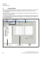
2.1 Program Window . . . . . . . . . . . . . . . . . . . . . . . . . . . . . . . . . . . . . . . . . . . . . . . . . . . . . 2-2
2.1.1 Menu bar . . . . . . . . . . . . . . . . . . . . . . . . . . . . . . . . . . . . . . . . . . . . . . . . . . . . . . . . 2-4
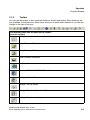
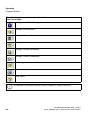
2.1.2 Toolbar . . . . . . . . . . . . . . . . . . . . . . . . . . . . . . . . . . . . . . . . . . . . . . . . . . . . . . . . . 2-5
2.1.3 System View/Net View and Station View . . . . . . . . . . . . . . . . . . . . . . . . . . . . . . . 2-7
2.1.4 Administration area . . . . . . . . . . . . . . . . . . . . . . . . . . . . . . . . . . . . . . . . . . . . . . . . 2-9
2.1.5 Status bar . . . . . . . . . . . . . . . . . . . . . . . . . . . . . . . . . . . . . . . . . . . . . . . . . . . . . . 2-11
2.2 Copying and Deleting Entries (Drag & Drop) . . . . . . . . . . . . . . . . . . . . . . . . . . . . . . . 2-11
2.3 Context Menu . . . . . . . . . . . . . . . . . . . . . . . . . . . . . . . . . . . . . . . . . . . . . . . . . . . . . . 2-12
2.4 Table Handling. . . . . . . . . . . . . . . . . . . . . . . . . . . . . . . . . . . . . . . . . . . . . . . . . . . . . . 2-13
2.5 Invoking Help . . . . . . . . . . . . . . . . . . . . . . . . . . . . . . . . . . . . . . . . . . . . . . . . . . . . . . . 2-15
3 Start and Log-on . . . . . . . . . . . . . . . . . . . . . . . . . . . . . . . . . . . . . . . . . . . . . . . . . . . . . 3-1
3.1 Logging on to Manager E . . . . . . . . . . . . . . . . . . . . . . . . . . . . . . . . . . . . . . . . . . . . . . 3-1
4 Starting up HiPath 5000 RSM/AllServe . . . . . . . . . . . . . . . . . . . . . . . . . . . . . . . . . . . . 4-1
4.1 Starting up a New HiPath 5000 RSM/AllServe System . . . . . . . . . . . . . . . . . . . . . . . . 4-2
4.1.1 Creating the server . . . . . . . . . . . . . . . . . . . . . . . . . . . . . . . . . . . . . . . . . . . . . . . . 4-2
A31003-H3590-M100-5-76A9, 11/2011
HiPath 3000 Manager E, Administrator Documentation
0-1
asseTOC.fm
Contents
Nur für den internen Gebrauch
4.1.2 Adding nodes . . . . . . . . . . . . . . . . . . . . . . . . . . . . . . . . . . . . . . . . . . . . . . . . . . . . . 4-3
4.1.3 Setting up the HiPath IP address (HIP) . . . . . . . . . . . . . . . . . . . . . . . . . . . . . . . . . 4-3
4.1.4 Configuring netwide call numbers . . . . . . . . . . . . . . . . . . . . . . . . . . . . . . . . . . . . . 4-4
4.1.5 Assigning HG 1500 channels to the last route and assigning the protocol . . . . . . 4-4
4.1.6 Assigning routing parameters to HG 1500 trunks. . . . . . . . . . . . . . . . . . . . . . . . . . 4-5
4.1.7 Configuring LCR . . . . . . . . . . . . . . . . . . . . . . . . . . . . . . . . . . . . . . . . . . . . . . . . . . . 4-5
4.1.8 Setting up a server IP address and node ID. . . . . . . . . . . . . . . . . . . . . . . . . . . . . . 4-7
4.1.9 Restarting the server service . . . . . . . . . . . . . . . . . . . . . . . . . . . . . . . . . . . . . . . . . 4-7
4.1.10 Logging on the HG 1500 card . . . . . . . . . . . . . . . . . . . . . . . . . . . . . . . . . . . . . . . 4-8
4.2 Administering an Existing HiPath 5000 RSM/AllServe System. . . . . . . . . . . . . . . . . . . 4-9
4.2.1 Transferring data from the node to the server . . . . . . . . . . . . . . . . . . . . . . . . . . . . 4-9
4.2.2 Mapping the configuration . . . . . . . . . . . . . . . . . . . . . . . . . . . . . . . . . . . . . . . . . . 4-10
4.2.3 Stations overview . . . . . . . . . . . . . . . . . . . . . . . . . . . . . . . . . . . . . . . . . . . . . . . . . 4-10
4.2.4 Administering the speed dialing destination . . . . . . . . . . . . . . . . . . . . . . . . . . . . . 4-11
4.2.5 Administering the HG 1500 card . . . . . . . . . . . . . . . . . . . . . . . . . . . . . . . . . . . . . 4-11
4.2.6 Administering HG 1500 call numbers . . . . . . . . . . . . . . . . . . . . . . . . . . . . . . . . . . 4-11
4.2.7 Logging on/off a node. . . . . . . . . . . . . . . . . . . . . . . . . . . . . . . . . . . . . . . . . . . . . . 4-12
4.2.8 Adding nodes . . . . . . . . . . . . . . . . . . . . . . . . . . . . . . . . . . . . . . . . . . . . . . . . . . . . 4-13
4.2.9 APS transfer . . . . . . . . . . . . . . . . . . . . . . . . . . . . . . . . . . . . . . . . . . . . . . . . . . . . . 4-13
4.2.10 Password protection . . . . . . . . . . . . . . . . . . . . . . . . . . . . . . . . . . . . . . . . . . . . . . 4-14
4.2.11 LOG file mechanism - Feature server status messages . . . . . . . . . . . . . . . . . . 4-14
4.2.12 Maintenance access. . . . . . . . . . . . . . . . . . . . . . . . . . . . . . . . . . . . . . . . . . . . . . 4-15
4.3 Settings for optiClient Attendant . . . . . . . . . . . . . . . . . . . . . . . . . . . . . . . . . . . . . . . . . 4-16
4.3.1 Setting the Central busy signaling flag . . . . . . . . . . . . . . . . . . . . . . . . . . . . . . . . . 4-16
4.3.2 Entering a PABX number for the last route . . . . . . . . . . . . . . . . . . . . . . . . . . . . . 4-16
4.4 Information on Inter-system Busy Signaling . . . . . . . . . . . . . . . . . . . . . . . . . . . . . . . . 4-16
4.5 Configuring Stations for the Use of Non-Voice Services. . . . . . . . . . . . . . . . . . . . . . . 4-17
4.5.1 HiPath 5000 RSM/AllServe network. . . . . . . . . . . . . . . . . . . . . . . . . . . . . . . . . . . 4-17
4.5.2 IP network. . . . . . . . . . . . . . . . . . . . . . . . . . . . . . . . . . . . . . . . . . . . . . . . . . . . . . . 4-18
4.6 Parameterizing for Media PC Streaming 1.0 (not in the USA) . . . . . . . . . . . . . . . . . . 4-19
4.6.1 Route configuration . . . . . . . . . . . . . . . . . . . . . . . . . . . . . . . . . . . . . . . . . . . . . . . 4-20
4.6.2 Configuring LCR . . . . . . . . . . . . . . . . . . . . . . . . . . . . . . . . . . . . . . . . . . . . . . . . . . 4-22
4.6.3 Media Streaming in the network . . . . . . . . . . . . . . . . . . . . . . . . . . . . . . . . . . . . . . 4-23
4.6.4 Configuring an HG 1500 card for Media Streaming . . . . . . . . . . . . . . . . . . . . . . . 4-23
4.6.5 Configuring announcements in connection with Media Streaming and HPCO . . 4-25
4.6.6 Configuring cross-node ACD groups . . . . . . . . . . . . . . . . . . . . . . . . . . . . . . . . . . 4-25
4.7 Central Busy Signaling with Attendant P. . . . . . . . . . . . . . . . . . . . . . . . . . . . . . . . . . . 4-27
5 Implementing Features . . . . . . . . . . . . . . . . . . . . . . . . . . . . . . . . . . . . . . . . . . . . . . . . . 5-1
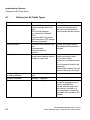
5.1 Features for All Traffic Types . . . . . . . . . . . . . . . . . . . . . . . . . . . . . . . . . . . . . . . . . . . . 5-2
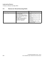
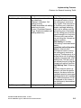
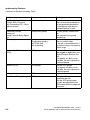
5.2 Features for General Incoming Traffic . . . . . . . . . . . . . . . . . . . . . . . . . . . . . . . . . . . . . 5-4
5.3 Features for General Outgoing Traffic . . . . . . . . . . . . . . . . . . . . . . . . . . . . . . . . . . . . . 5-9
5.4 Features for General External Traffic . . . . . . . . . . . . . . . . . . . . . . . . . . . . . . . . . . . . . 5-11
5.5 Features for Incoming External Traffic . . . . . . . . . . . . . . . . . . . . . . . . . . . . . . . . . . . . 5-12
5.6 Features for Outgoing External Traffic . . . . . . . . . . . . . . . . . . . . . . . . . . . . . . . . . . . . 5-15
0-2
A31003-H3590-M100-5-76A9, 11/2011
HiPath 3000 Manager E, Administrator Documentation
asseTOC.fm
Nur für den internen Gebrauch
Contents
5.7 Least Cost Routing (LCR) . . . . . . . . . . . . . . . . . . . . . . . . . . . . . . . . . . . . . . . . . . . . .
5.8 Features for Internal Traffic . . . . . . . . . . . . . . . . . . . . . . . . . . . . . . . . . . . . . . . . . . . .
5.9 Tenant Service. . . . . . . . . . . . . . . . . . . . . . . . . . . . . . . . . . . . . . . . . . . . . . . . . . . . . .
5.10 Other Features. . . . . . . . . . . . . . . . . . . . . . . . . . . . . . . . . . . . . . . . . . . . . . . . . . . . .
5.11 Network . . . . . . . . . . . . . . . . . . . . . . . . . . . . . . . . . . . . . . . . . . . . . . . . . . . . . . . . . .
5.12 Features for Call Detail Recording. . . . . . . . . . . . . . . . . . . . . . . . . . . . . . . . . . . . . .
5.13 ISDN Features . . . . . . . . . . . . . . . . . . . . . . . . . . . . . . . . . . . . . . . . . . . . . . . . . . . . .
5.14 Small Remote Site Concept. . . . . . . . . . . . . . . . . . . . . . . . . . . . . . . . . . . . . . . . . . .
5.15 Mobility Entry (not for U.S.) . . . . . . . . . . . . . . . . . . . . . . . . . . . . . . . . . . . . . . . . . . .
5-18
5-19
5-21
5-22
5-25
5-27
5-29
5-31
5-32
6 Menu Overviews . . . . . . . . . . . . . . . . . . . . . . . . . . . . . . . . . . . . . . . . . . . . . . . . . . . . . .
6.1 File . . . . . . . . . . . . . . . . . . . . . . . . . . . . . . . . . . . . . . . . . . . . . . . . . . . . . . . . . . . . . . . .
6.2 Settings . . . . . . . . . . . . . . . . . . . . . . . . . . . . . . . . . . . . . . . . . . . . . . . . . . . . . . . . . . . .
6.3 System Status . . . . . . . . . . . . . . . . . . . . . . . . . . . . . . . . . . . . . . . . . . . . . . . . . . . . . . .
6.4 Tools . . . . . . . . . . . . . . . . . . . . . . . . . . . . . . . . . . . . . . . . . . . . . . . . . . . . . . . . . . . . . .
6.5 Options . . . . . . . . . . . . . . . . . . . . . . . . . . . . . . . . . . . . . . . . . . . . . . . . . . . . . . . . . . . .
6.6 Applications . . . . . . . . . . . . . . . . . . . . . . . . . . . . . . . . . . . . . . . . . . . . . . . . . . . . . . . . .
6.7 Help . . . . . . . . . . . . . . . . . . . . . . . . . . . . . . . . . . . . . . . . . . . . . . . . . . . . . . . . . . . . . . .
6-1
6-1
6-3
6-6
6-6
6-7
6-7
6-7
7 Station view . . . . . . . . . . . . . . . . . . . . . . . . . . . . . . . . . . . . . . . . . . . . . . . . . . . . . . . . . . 7-1
7.1 Station Selection . . . . . . . . . . . . . . . . . . . . . . . . . . . . . . . . . . . . . . . . . . . . . . . . . . . . . 7-2
7.2 Station Parameters . . . . . . . . . . . . . . . . . . . . . . . . . . . . . . . . . . . . . . . . . . . . . . . . . . . 7-3
7.2.1 Station view: Flags . . . . . . . . . . . . . . . . . . . . . . . . . . . . . . . . . . . . . . . . . . . . . . . . 7-6
7.2.2 Station view: Activated features . . . . . . . . . . . . . . . . . . . . . . . . . . . . . . . . . . . . . 7-17
7.2.3 Station view: Workpoint Client. . . . . . . . . . . . . . . . . . . . . . . . . . . . . . . . . . . . . . . 7-21
7.2.4 Station view: Groups . . . . . . . . . . . . . . . . . . . . . . . . . . . . . . . . . . . . . . . . . . . . . . 7-25
7.2.5 Station view: Forwarding . . . . . . . . . . . . . . . . . . . . . . . . . . . . . . . . . . . . . . . . . . . 7-26
7.2.6 Station view: BRI (only in the USA). . . . . . . . . . . . . . . . . . . . . . . . . . . . . . . . . . . 7-27
7.2.7 Station view: Template Editor . . . . . . . . . . . . . . . . . . . . . . . . . . . . . . . . . . . . . . . 7-28
7.2.8 Station view: ISDN flags . . . . . . . . . . . . . . . . . . . . . . . . . . . . . . . . . . . . . . . . . . . 7-28
8 File Menu . . . . . . . . . . . . . . . . . . . . . . . . . . . . . . . . . . . . . . . . . . . . . . . . . . . . . . . . . . . . 8-1
8.1 New | HiPath 3000 . . . . . . . . . . . . . . . . . . . . . . . . . . . . . . . . . . . . . . . . . . . . . . . . . . . . 8-3
8.2 New | HiPath 5000 RSM/AllServe Server . . . . . . . . . . . . . . . . . . . . . . . . . . . . . . . . . . 8-4
8.3 Delete | HiPath 3000 . . . . . . . . . . . . . . . . . . . . . . . . . . . . . . . . . . . . . . . . . . . . . . . . . . 8-6
8.4 Transfer | HiPath 5000 RSM/AllServe Server . . . . . . . . . . . . . . . . . . . . . . . . . . . . . . . 8-7
8.5 New . . . . . . . . . . . . . . . . . . . . . . . . . . . . . . . . . . . . . . . . . . . . . . . . . . . . . . . . . . . . . . 8-10
8.6 Open Customer Database . . . . . . . . . . . . . . . . . . . . . . . . . . . . . . . . . . . . . . . . . . . . . 8-11
8.7 Save Customer Database . . . . . . . . . . . . . . . . . . . . . . . . . . . . . . . . . . . . . . . . . . . . . 8-13
8.8 Save Customer Database As . . . . . . . . . . . . . . . . . . . . . . . . . . . . . . . . . . . . . . . . . . 8-14
8.9 Close Customer Database. . . . . . . . . . . . . . . . . . . . . . . . . . . . . . . . . . . . . . . . . . . . . 8-15
8.10 Output Customer Database . . . . . . . . . . . . . . . . . . . . . . . . . . . . . . . . . . . . . . . . . . . 8-16
8.11 Compare Customer Database . . . . . . . . . . . . . . . . . . . . . . . . . . . . . . . . . . . . . . . . . 8-17
8.12 Convert Customer Database . . . . . . . . . . . . . . . . . . . . . . . . . . . . . . . . . . . . . . . . . . 8-18
8.13 Load APS Texts . . . . . . . . . . . . . . . . . . . . . . . . . . . . . . . . . . . . . . . . . . . . . . . . . . . . 8-21
8.14 Append CDB to APS . . . . . . . . . . . . . . . . . . . . . . . . . . . . . . . . . . . . . . . . . . . . . . . . 8-22
A31003-H3590-M100-5-76A9, 11/2011
HiPath 3000 Manager E, Administrator Documentation
0-3
asseTOC.fm
Contents
Nur für den internen Gebrauch
8.15 Print / Print Preview. . . . . . . . . . . . . . . . . . . . . . . . . . . . . . . . . . . . . . . . . . . . . . . . . . 8-23
8.16 Printer Setup . . . . . . . . . . . . . . . . . . . . . . . . . . . . . . . . . . . . . . . . . . . . . . . . . . . . . . . 8-23
8.17 Output MDF Plan . . . . . . . . . . . . . . . . . . . . . . . . . . . . . . . . . . . . . . . . . . . . . . . . . . . 8-24
8.18 Generate System Info Files. . . . . . . . . . . . . . . . . . . . . . . . . . . . . . . . . . . . . . . . . . . . 8-24
8.19 Transfer. . . . . . . . . . . . . . . . . . . . . . . . . . . . . . . . . . . . . . . . . . . . . . . . . . . . . . . . . . . 8-25
8.19.1 Transfer | Communication . . . . . . . . . . . . . . . . . . . . . . . . . . . . . . . . . . . . . . . . . 8-26
8.19.2 Transfer | Communication | Maintenance. . . . . . . . . . . . . . . . . . . . . . . . . . . . . . 8-36
8.19.3 Maintenance | | Event Log . . . . . . . . . . . . . . . . . . . . . . . . . . . . . . . . . . . . . . . . . 8-38
8.19.4 Maintenance | Restart/Reload . . . . . . . . . . . . . . . . . . . . . . . . . . . . . . . . . . . . . . 8-40
8.19.5 Maintenance | Out of Service . . . . . . . . . . . . . . . . . . . . . . . . . . . . . . . . . . . . . . . 8-41
8.19.6 Maintenance | Base Station Status (not in the USA) . . . . . . . . . . . . . . . . . . . . . 8-43
8.19.7 Maintenance | Trunk Status . . . . . . . . . . . . . . . . . . . . . . . . . . . . . . . . . . . . . . . . 8-46
8.19.8 Maintenance | Trunk Error Counter . . . . . . . . . . . . . . . . . . . . . . . . . . . . . . . . . . 8-47
8.19.9 Maintenance | Call Monitoring . . . . . . . . . . . . . . . . . . . . . . . . . . . . . . . . . . . . . . 8-48
8.19.10 Maintenance | Station Status . . . . . . . . . . . . . . . . . . . . . . . . . . . . . . . . . . . . . . 8-51
8.19.11 Maintenance | V.24 Status . . . . . . . . . . . . . . . . . . . . . . . . . . . . . . . . . . . . . . . . 8-53
8.19.12 Maintenance | Card status . . . . . . . . . . . . . . . . . . . . . . . . . . . . . . . . . . . . . . . . 8-54
8.19.13 Maintenance | IVM (only if an IVM card is plugged in) . . . . . . . . . . . . . . . . . . . 8-56
8.19.14 Maintenance | IVM: Language selection . . . . . . . . . . . . . . . . . . . . . . . . . . . . . 8-58
8.19.15 Maintenance | IVM: Reset passwords . . . . . . . . . . . . . . . . . . . . . . . . . . . . . . . 8-59
8.19.16 Maintenance | IVM: Initialize mailboxes . . . . . . . . . . . . . . . . . . . . . . . . . . . . . . 8-60
8.19.17 Maintenance | IVM: Change super user password. . . . . . . . . . . . . . . . . . . . . . 8-61
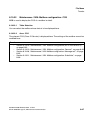
8.19.18 Maintenance | IVM: Mailbox configuration (as of IVM Version 2). . . . . . . . . . . 8-62
8.19.19 Maintenance | IVM: Mailbox configuration: General. . . . . . . . . . . . . . . . . . . . . 8-63
8.19.20 Maintenance | IVM: Mailbox configuration: Message call. . . . . . . . . . . . . . . . . 8-65
8.19.21 Maintenance | IVM: Mailbox configuration: Substitute . . . . . . . . . . . . . . . . . . . 8-66
8.19.22 Maintenance | IVM: Mailbox configuration: COS . . . . . . . . . . . . . . . . . . . . . . . 8-67
8.19.23 Maintenance | IVM: Mailbox configuration: Personal week plan . . . . . . . . . . . 8-68
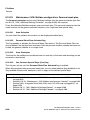
8.19.24 Maintenance | IVM: Mailbox configuration: E-mail notification . . . . . . . . . . . . . 8-69
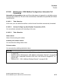
8.19.25 Maintenance | IVM: Mailbox Configuration: Automatic Call Forwarding. . . . . . 8-71
8.19.26 Maintenance | IVM: Execute file operations . . . . . . . . . . . . . . . . . . . . . . . . . . . 8-72
8.19.27 Maintenance | IVM: Execute file operations: Display Statistical Data . . . . . . . 8-76
8.19.28 Maintenance | EVM . . . . . . . . . . . . . . . . . . . . . . . . . . . . . . . . . . . . . . . . . . . . . 8-77
8.19.29 Maintenance | EVM: Initialize mailboxes . . . . . . . . . . . . . . . . . . . . . . . . . . . . . 8-79
8.19.30 Maintenance | EVM: Execute file operations . . . . . . . . . . . . . . . . . . . . . . . . . . 8-80
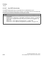
8.19.31 Maintenance | OpenStage Phones: Event Log . . . . . . . . . . . . . . . . . . . . . . . . 8-84
8.19.32 Maintenance | OpenStage Phones: SW distribution . . . . . . . . . . . . . . . . . . . . 8-85
8.19.33 Maintenance | OpenStage Phones: Trace . . . . . . . . . . . . . . . . . . . . . . . . . . . . 8-89
8.19.34 Maintenance | Trace Settings. . . . . . . . . . . . . . . . . . . . . . . . . . . . . . . . . . . . . . 8-94
8.19.35 Transfer | Communication | Security . . . . . . . . . . . . . . . . . . . . . . . . . . . . . . . 8-100
8.19.36 Security | User administration. . . . . . . . . . . . . . . . . . . . . . . . . . . . . . . . . . . . . 8-101
8.19.37 Security | Protocol . . . . . . . . . . . . . . . . . . . . . . . . . . . . . . . . . . . . . . . . . . . . . 8-103
8.19.38 Transfer | Callback connection . . . . . . . . . . . . . . . . . . . . . . . . . . . . . . . . . . . . 8-105
8.19.39 Transfer | Loadable texts . . . . . . . . . . . . . . . . . . . . . . . . . . . . . . . . . . . . . . . . 8-106
0-4
A31003-H3590-M100-5-76A9, 11/2011
HiPath 3000 Manager E, Administrator Documentation
asseTOC.fm
Nur für den internen Gebrauch
Contents
8.19.40 Transfer | SW Transfer . . . . . . . . . . . . . . . . . . . . . . . . . . . . . . . . . . . . . . . . . 8-107
8.20 Exit . . . . . . . . . . . . . . . . . . . . . . . . . . . . . . . . . . . . . . . . . . . . . . . . . . . . . . . . . . . . . 8-109
9 Settings Menu . . . . . . . . . . . . . . . . . . . . . . . . . . . . . . . . . . . . . . . . . . . . . . . . . . . . . . . . 9-1
9.1 Settings | Netwide Data . . . . . . . . . . . . . . . . . . . . . . . . . . . . . . . . . . . . . . . . . . . . . . . . 9-2
9.1.1 Stations - Netwide Data. . . . . . . . . . . . . . . . . . . . . . . . . . . . . . . . . . . . . . . . . . . . . 9-3
9.1.2 Netwide Data. . . . . . . . . . . . . . . . . . . . . . . . . . . . . . . . . . . . . . . . . . . . . . . . . . . . . 9-8
9.1.3 Resource Management (HiPath 5000 RSM/AllServe) . . . . . . . . . . . . . . . . . . . . 9-10
9.2 Settings | Set up station . . . . . . . . . . . . . . . . . . . . . . . . . . . . . . . . . . . . . . . . . . . . . . . 9-11
9.2.1 Subscriber . . . . . . . . . . . . . . . . . . . . . . . . . . . . . . . . . . . . . . . . . . . . . . . . . . . . . . 9-12
9.2.2 Key programming . . . . . . . . . . . . . . . . . . . . . . . . . . . . . . . . . . . . . . . . . . . . . . . . 9-16
9.2.3 Key programming: Fill/Delete . . . . . . . . . . . . . . . . . . . . . . . . . . . . . . . . . . . . . . . 9-24
9.2.4 Key programming: Print. . . . . . . . . . . . . . . . . . . . . . . . . . . . . . . . . . . . . . . . . . . . 9-25
9.2.5 Terminal hw sw version. . . . . . . . . . . . . . . . . . . . . . . . . . . . . . . . . . . . . . . . . . . . 9-26
9.2.6 Fax/Modem . . . . . . . . . . . . . . . . . . . . . . . . . . . . . . . . . . . . . . . . . . . . . . . . . . . . . 9-28
9.2.7 Emergency . . . . . . . . . . . . . . . . . . . . . . . . . . . . . . . . . . . . . . . . . . . . . . . . . . . . . 9-29
9.2.8 Mobility Entry (not for USA). . . . . . . . . . . . . . . . . . . . . . . . . . . . . . . . . . . . . . . . . 9-31
9.2.9 HXG configuration (V4.0 and earlier) . . . . . . . . . . . . . . . . . . . . . . . . . . . . . . . . . 9-33
9.2.10 Gatekeeper (V5.0 and Later) . . . . . . . . . . . . . . . . . . . . . . . . . . . . . . . . . . . . . . 9-34
9.2.11 Gateway (V5.0 and Later) . . . . . . . . . . . . . . . . . . . . . . . . . . . . . . . . . . . . . . . . . 9-36
9.2.12 OSO Ports . . . . . . . . . . . . . . . . . . . . . . . . . . . . . . . . . . . . . . . . . . . . . . . . . . . . . 9-37
9.3 Settings | Cordless (Not in the USA) . . . . . . . . . . . . . . . . . . . . . . . . . . . . . . . . . . . . . 9-39
9.3.1 Cordless | System-wide. . . . . . . . . . . . . . . . . . . . . . . . . . . . . . . . . . . . . . . . . . . . 9-40
9.3.2 Cordless | SLC . . . . . . . . . . . . . . . . . . . . . . . . . . . . . . . . . . . . . . . . . . . . . . . . . . 9-43
9.3.3 Cordless | Multi-SLC . . . . . . . . . . . . . . . . . . . . . . . . . . . . . . . . . . . . . . . . . . . . . . 9-46
9.3.4 Cordless | Base station . . . . . . . . . . . . . . . . . . . . . . . . . . . . . . . . . . . . . . . . . . . . 9-48
9.4 Settings | Lines/networking . . . . . . . . . . . . . . . . . . . . . . . . . . . . . . . . . . . . . . . . . . . . 9-50
9.4.1 Trunks . . . . . . . . . . . . . . . . . . . . . . . . . . . . . . . . . . . . . . . . . . . . . . . . . . . . . . . . . 9-51
9.4.2 Buttons . . . . . . . . . . . . . . . . . . . . . . . . . . . . . . . . . . . . . . . . . . . . . . . . . . . . . . . . 9-53
9.4.3 Trunks | Parameter/ISDN flags . . . . . . . . . . . . . . . . . . . . . . . . . . . . . . . . . . . . . . 9-54
9.4.4 Trunks | Parameter/MSI flags . . . . . . . . . . . . . . . . . . . . . . . . . . . . . . . . . . . . . . . 9-62
9.4.5 Trunks | Parameter/General Flags . . . . . . . . . . . . . . . . . . . . . . . . . . . . . . . . . . . 9-66
9.4.6 Trunks | Parameter/TMANI Parameter . . . . . . . . . . . . . . . . . . . . . . . . . . . . . . . . 9-69
9.4.7 Trunks | Parameter/Template Editor . . . . . . . . . . . . . . . . . . . . . . . . . . . . . . . . . . 9-73
9.4.8 Routes . . . . . . . . . . . . . . . . . . . . . . . . . . . . . . . . . . . . . . . . . . . . . . . . . . . . . . . . . 9-74
9.4.9 Routing parameters. . . . . . . . . . . . . . . . . . . . . . . . . . . . . . . . . . . . . . . . . . . . . . . 9-83
9.4.10 ISDN parameters. . . . . . . . . . . . . . . . . . . . . . . . . . . . . . . . . . . . . . . . . . . . . . . . 9-91
9.4.11 LCOSS . . . . . . . . . . . . . . . . . . . . . . . . . . . . . . . . . . . . . . . . . . . . . . . . . . . . . . . 9-95
9.4.12 PRI (US only) . . . . . . . . . . . . . . . . . . . . . . . . . . . . . . . . . . . . . . . . . . . . . . . . . . 9-97
9.4.13 QSIG features (not in the USA). . . . . . . . . . . . . . . . . . . . . . . . . . . . . . . . . . . . . 9-98
9.4.14 IP Trunks for HG 1500 . . . . . . . . . . . . . . . . . . . . . . . . . . . . . . . . . . . . . . . . . . 9-100
9.4.15 IP trunks for SIP providers and OpenScape Office . . . . . . . . . . . . . . . . . . . . . 9-102
9.4.16 E.164 Table . . . . . . . . . . . . . . . . . . . . . . . . . . . . . . . . . . . . . . . . . . . . . . . . . . . 9-104
9.5 Settings | Least Cost Routing . . . . . . . . . . . . . . . . . . . . . . . . . . . . . . . . . . . . . . . . . 9-106
9.5.1 Flags and COS . . . . . . . . . . . . . . . . . . . . . . . . . . . . . . . . . . . . . . . . . . . . . . . . . 9-107
A31003-H3590-M100-5-76A9, 11/2011
HiPath 3000 Manager E, Administrator Documentation
0-5
asseTOC.fm
Contents
Nur für den internen Gebrauch
9.5.2 Dial plan . . . . . . . . . . . . . . . . . . . . . . . . . . . . . . . . . . . . . . . . . . . . . . . . . . . . . . .
9.5.3 Schedule. . . . . . . . . . . . . . . . . . . . . . . . . . . . . . . . . . . . . . . . . . . . . . . . . . . . . . .
9.6 Settings | Incoming calls . . . . . . . . . . . . . . . . . . . . . . . . . . . . . . . . . . . . . . . . . . . . . .
9.6.1 Call Pickup . . . . . . . . . . . . . . . . . . . . . . . . . . . . . . . . . . . . . . . . . . . . . . . . . . . . .
9.6.2 Ringing assignment per line . . . . . . . . . . . . . . . . . . . . . . . . . . . . . . . . . . . . . . . .
9.6.3 Call forwarding . . . . . . . . . . . . . . . . . . . . . . . . . . . . . . . . . . . . . . . . . . . . . . . . . .
9.6.4 Groups/hunt groups . . . . . . . . . . . . . . . . . . . . . . . . . . . . . . . . . . . . . . . . . . . . . .
9.6.5 Groups/Hunt groups | Station parameters . . . . . . . . . . . . . . . . . . . . . . . . . . . . .
9.6.6 Groups/Hunt Group | Group Membership . . . . . . . . . . . . . . . . . . . . . . . . . . . . .
9.6.7 Groups/Hunt groups | External destinations. . . . . . . . . . . . . . . . . . . . . . . . . . . .
9.6.8 Team/top . . . . . . . . . . . . . . . . . . . . . . . . . . . . . . . . . . . . . . . . . . . . . . . . . . . . . .
9.6.9 Edit team/top . . . . . . . . . . . . . . . . . . . . . . . . . . . . . . . . . . . . . . . . . . . . . . . . . . .
9.6.10 UCD parameters. . . . . . . . . . . . . . . . . . . . . . . . . . . . . . . . . . . . . . . . . . . . . . . .
9.6.11 UCD groups . . . . . . . . . . . . . . . . . . . . . . . . . . . . . . . . . . . . . . . . . . . . . . . . . . .
9.7 Settings | Classes of service . . . . . . . . . . . . . . . . . . . . . . . . . . . . . . . . . . . . . . . . . . .
9.7.1 Station . . . . . . . . . . . . . . . . . . . . . . . . . . . . . . . . . . . . . . . . . . . . . . . . . . . . . . . .
9.7.2 Day or Night . . . . . . . . . . . . . . . . . . . . . . . . . . . . . . . . . . . . . . . . . . . . . . . . . . . .
9.7.3 Allowed/Denied numbers . . . . . . . . . . . . . . . . . . . . . . . . . . . . . . . . . . . . . . . . . .
9.7.4 CON matrix. . . . . . . . . . . . . . . . . . . . . . . . . . . . . . . . . . . . . . . . . . . . . . . . . . . . .
9.7.5 Group assignment . . . . . . . . . . . . . . . . . . . . . . . . . . . . . . . . . . . . . . . . . . . . . . .
9.7.6 Overview. . . . . . . . . . . . . . . . . . . . . . . . . . . . . . . . . . . . . . . . . . . . . . . . . . . . . . .
9.7.7 Autom. night service . . . . . . . . . . . . . . . . . . . . . . . . . . . . . . . . . . . . . . . . . . . . . .
9.7.8 Special days . . . . . . . . . . . . . . . . . . . . . . . . . . . . . . . . . . . . . . . . . . . . . . . . . . . .
9.7.9 autom. COS changeover . . . . . . . . . . . . . . . . . . . . . . . . . . . . . . . . . . . . . . . . . .
9.8 Settings | System Parameters. . . . . . . . . . . . . . . . . . . . . . . . . . . . . . . . . . . . . . . . . .
9.8.1 Flags. . . . . . . . . . . . . . . . . . . . . . . . . . . . . . . . . . . . . . . . . . . . . . . . . . . . . . . . . .
9.8.2 LDAP . . . . . . . . . . . . . . . . . . . . . . . . . . . . . . . . . . . . . . . . . . . . . . . . . . . . . . . . .
9.8.3 System settings . . . . . . . . . . . . . . . . . . . . . . . . . . . . . . . . . . . . . . . . . . . . . . . . .
9.8.4 Intercept / Attendant . . . . . . . . . . . . . . . . . . . . . . . . . . . . . . . . . . . . . . . . . . . . . .
9.8.5 Display . . . . . . . . . . . . . . . . . . . . . . . . . . . . . . . . . . . . . . . . . . . . . . . . . . . . . . . .
9.8.6 Flexible menus . . . . . . . . . . . . . . . . . . . . . . . . . . . . . . . . . . . . . . . . . . . . . . . . . .
9.8.7 Speed dialing system . . . . . . . . . . . . . . . . . . . . . . . . . . . . . . . . . . . . . . . . . . . . .
9.8.8 Service codes . . . . . . . . . . . . . . . . . . . . . . . . . . . . . . . . . . . . . . . . . . . . . . . . . . .
9.8.9 Texts. . . . . . . . . . . . . . . . . . . . . . . . . . . . . . . . . . . . . . . . . . . . . . . . . . . . . . . . . .
9.8.10 Time parameters . . . . . . . . . . . . . . . . . . . . . . . . . . . . . . . . . . . . . . . . . . . . . . .
9.8.11 Tones and ring types . . . . . . . . . . . . . . . . . . . . . . . . . . . . . . . . . . . . . . . . . . . .
9.8.12 Daylight saving time/DISA . . . . . . . . . . . . . . . . . . . . . . . . . . . . . . . . . . . . . . . .
9.8.13 Plus Products Flags/MW . . . . . . . . . . . . . . . . . . . . . . . . . . . . . . . . . . . . . . . . .
9.9 Settings | Auxiliary equipment. . . . . . . . . . . . . . . . . . . . . . . . . . . . . . . . . . . . . . . . . .
9.9.1 Ext. connection . . . . . . . . . . . . . . . . . . . . . . . . . . . . . . . . . . . . . . . . . . . . . . . . . .
9.9.2 Actuators . . . . . . . . . . . . . . . . . . . . . . . . . . . . . . . . . . . . . . . . . . . . . . . . . . . . . .
9.9.3 Announcement . . . . . . . . . . . . . . . . . . . . . . . . . . . . . . . . . . . . . . . . . . . . . . . . . .
9.9.4 Announcement | External destinations . . . . . . . . . . . . . . . . . . . . . . . . . . . . . . . .
9.9.5 Paging . . . . . . . . . . . . . . . . . . . . . . . . . . . . . . . . . . . . . . . . . . . . . . . . . . . . . . . .
0-6
9-109
9-122
9-124
9-125
9-126
9-129
9-133
9-138
9-141
9-143
9-144
9-148
9-150
9-152
9-155
9-156
9-157
9-160
9-162
9-165
9-167
9-169
9-171
9-172
9-175
9-176
9-190
9-193
9-201
9-207
9-212
9-213
9-217
9-219
9-220
9-229
9-231
9-235
9-238
9-239
9-241
9-245
9-248
9-249
A31003-H3590-M100-5-76A9, 11/2011
HiPath 3000 Manager E, Administrator Documentation
asseTOC.fm
Nur für den internen Gebrauch
Contents
9.9.6 Sensors . . . . . . . . . . . . . . . . . . . . . . . . . . . . . . . . . . . . . . . . . . . . . . . . . . . . . . .
9.9.7 PhoneMail . . . . . . . . . . . . . . . . . . . . . . . . . . . . . . . . . . . . . . . . . . . . . . . . . . . . .
9.9.8 Integrated Voice Mail (IVM) (only if an IVM card is plugged-in) . . . . . . . . . . . .
9.9.9 IVM | Parameter/Mailbox Parameters . . . . . . . . . . . . . . . . . . . . . . . . . . . . . . . .
9.9.10 IVM | Parameter/COS . . . . . . . . . . . . . . . . . . . . . . . . . . . . . . . . . . . . . . . . . . .
9.9.11 IVM | Additional Settings/General . . . . . . . . . . . . . . . . . . . . . . . . . . . . . . . . . .
9.9.12 IVM | Additional settings/Advanced. . . . . . . . . . . . . . . . . . . . . . . . . . . . . . . . .
9.9.13 IVM | Additional settings/Network parameters . . . . . . . . . . . . . . . . . . . . . . . .
9.9.14 IVM | Additional settings /Automatic attendant . . . . . . . . . . . . . . . . . . . . . . . .
9.9.15 IVM | Additional Settings/Calendar . . . . . . . . . . . . . . . . . . . . . . . . . . . . . . . . .
9.9.16 IVM | Additional Settings/Central distribution list . . . . . . . . . . . . . . . . . . . . . .
9.9.17 IVM | Additional Settings/Group mailbox. . . . . . . . . . . . . . . . . . . . . . . . . . . . .
9.9.18 EVM (Entry Voice Mail) . . . . . . . . . . . . . . . . . . . . . . . . . . . . . . . . . . . . . . . . . .
9.9.19 EVM | Additional settings/General. . . . . . . . . . . . . . . . . . . . . . . . . . . . . . . . . .
9.9.20 EVM | Additional settings / Automatic attendant: . . . . . . . . . . . . . . . . . . . . . .
9.10 Settings | Network . . . . . . . . . . . . . . . . . . . . . . . . . . . . . . . . . . . . . . . . . . . . . . . . .
9.10.1 Basic settings . . . . . . . . . . . . . . . . . . . . . . . . . . . . . . . . . . . . . . . . . . . . . . . . .
9.10.2 IP parameters . . . . . . . . . . . . . . . . . . . . . . . . . . . . . . . . . . . . . . . . . . . . . . . . .
9.10.3 SNMP Data . . . . . . . . . . . . . . . . . . . . . . . . . . . . . . . . . . . . . . . . . . . . . . . . . . .
9.10.4 SNMP partner/Communication Partner. . . . . . . . . . . . . . . . . . . . . . . . . . . . . .
9.10.5 PSTN partner . . . . . . . . . . . . . . . . . . . . . . . . . . . . . . . . . . . . . . . . . . . . . . . . .
9.10.6 Edit PSTN partner . . . . . . . . . . . . . . . . . . . . . . . . . . . . . . . . . . . . . . . . . . . . . .
9.10.7 Firewall . . . . . . . . . . . . . . . . . . . . . . . . . . . . . . . . . . . . . . . . . . . . . . . . . . . . . .
9.10.8 Firewall | Edit IP firewall . . . . . . . . . . . . . . . . . . . . . . . . . . . . . . . . . . . . . . . . .
9.10.9 Firewall | Edit application firewall . . . . . . . . . . . . . . . . . . . . . . . . . . . . . . . . . .
9.10.10 Routing . . . . . . . . . . . . . . . . . . . . . . . . . . . . . . . . . . . . . . . . . . . . . . . . . . . . .
9.10.11 Routing | Edit IP routing . . . . . . . . . . . . . . . . . . . . . . . . . . . . . . . . . . . . . . . .
9.10.12 Mapping . . . . . . . . . . . . . . . . . . . . . . . . . . . . . . . . . . . . . . . . . . . . . . . . . . . .
9.10.13 Mapping | Edit IP mapping . . . . . . . . . . . . . . . . . . . . . . . . . . . . . . . . . . . . . .
9.10.14 HiPath 5000 RSM/AllServe Parameters . . . . . . . . . . . . . . . . . . . . . . . . . . . .
9.10.15 Gatekeeper . . . . . . . . . . . . . . . . . . . . . . . . . . . . . . . . . . . . . . . . . . . . . . . . . .
9.10.16 Ext. H.323-GK . . . . . . . . . . . . . . . . . . . . . . . . . . . . . . . . . . . . . . . . . . . . . . . .
9.10.17 Ext. SIP . . . . . . . . . . . . . . . . . . . . . . . . . . . . . . . . . . . . . . . . . . . . . . . . . . . . .
9.10.18 IP Ports . . . . . . . . . . . . . . . . . . . . . . . . . . . . . . . . . . . . . . . . . . . . . . . . . . . . .
9.10.19 Resource Management . . . . . . . . . . . . . . . . . . . . . . . . . . . . . . . . . . . . . . . . .
9.11 Settings | Licensing . . . . . . . . . . . . . . . . . . . . . . . . . . . . . . . . . . . . . . . . . . . . . . . .
9.11.1 Licensing – HXG . . . . . . . . . . . . . . . . . . . . . . . . . . . . . . . . . . . . . . . . . . . . . . .
9.11.2 Licensing – Base Station (not in the USA) . . . . . . . . . . . . . . . . . . . . . . . . . . .
9.11.3 Licensing – S2M . . . . . . . . . . . . . . . . . . . . . . . . . . . . . . . . . . . . . . . . . . . . . . .
9.11.4 Licensing – IVM. . . . . . . . . . . . . . . . . . . . . . . . . . . . . . . . . . . . . . . . . . . . . . . .
9.11.5 Licensing – System-wide. . . . . . . . . . . . . . . . . . . . . . . . . . . . . . . . . . . . . . . . .
9-250
9-253
9-255
9-259
9-263
9-268
9-274
9-276
9-278
9-280
9-282
9-284
9-286
9-289
9-292
9-294
9-295
9-299
9-303
9-305
9-309
9-310
9-314
9-316
9-318
9-320
9-321
9-322
9-323
9-324
9-325
9-328
9-330
9-333
9-335
9-336
9-337
9-338
9-339
9-340
9-341
10 System Status Menu. . . . . . . . . . . . . . . . . . . . . . . . . . . . . . . . . . . . . . . . . . . . . . . . . 10-1
10.1 System-wide . . . . . . . . . . . . . . . . . . . . . . . . . . . . . . . . . . . . . . . . . . . . . . . . . . . . . . 10-2
10.1.1 Cards. . . . . . . . . . . . . . . . . . . . . . . . . . . . . . . . . . . . . . . . . . . . . . . . . . . . . . . . . 10-3
A31003-H3590-M100-5-76A9, 11/2011
HiPath 3000 Manager E, Administrator Documentation
0-7
asseTOC.fm
Contents
Nur für den internen Gebrauch
10.1.2 Card Configuration | T1 Configuration . . . . . . . . . . . . . . . . . . . . . . . . . . . . . . . . 10-7
10.1.3 Card Configuration | Card data. . . . . . . . . . . . . . . . . . . . . . . . . . . . . . . . . . . . . . 10-8
10.1.4 Loadware . . . . . . . . . . . . . . . . . . . . . . . . . . . . . . . . . . . . . . . . . . . . . . . . . . . . . 10-11
10.1.5 System . . . . . . . . . . . . . . . . . . . . . . . . . . . . . . . . . . . . . . . . . . . . . . . . . . . . . . . 10-12
10.1.6 Flags. . . . . . . . . . . . . . . . . . . . . . . . . . . . . . . . . . . . . . . . . . . . . . . . . . . . . . . . . 10-15
10.1.7 Forwarding . . . . . . . . . . . . . . . . . . . . . . . . . . . . . . . . . . . . . . . . . . . . . . . . . . . . 10-16
10.1.8 Line states . . . . . . . . . . . . . . . . . . . . . . . . . . . . . . . . . . . . . . . . . . . . . . . . . . . . 10-18
10.1.9 System texts . . . . . . . . . . . . . . . . . . . . . . . . . . . . . . . . . . . . . . . . . . . . . . . . . . . 10-19
10.1.10 UCD Agents . . . . . . . . . . . . . . . . . . . . . . . . . . . . . . . . . . . . . . . . . . . . . . . . . . 10-20
10.2 Call charges . . . . . . . . . . . . . . . . . . . . . . . . . . . . . . . . . . . . . . . . . . . . . . . . . . . . . . 10-21
10.2.1 Stations (Not in the USA) . . . . . . . . . . . . . . . . . . . . . . . . . . . . . . . . . . . . . . . . . 10-22
10.2.2 Trunks (Not in the USA) . . . . . . . . . . . . . . . . . . . . . . . . . . . . . . . . . . . . . . . . . . 10-23
10.2.3 Output format . . . . . . . . . . . . . . . . . . . . . . . . . . . . . . . . . . . . . . . . . . . . . . . . . . 10-24
10.2.4 Output format | LAN settings . . . . . . . . . . . . . . . . . . . . . . . . . . . . . . . . . . . . . . 10-29
10.2.5 Factors (Not in the USA) . . . . . . . . . . . . . . . . . . . . . . . . . . . . . . . . . . . . . . . . . 10-31
10.2.6 Account codes . . . . . . . . . . . . . . . . . . . . . . . . . . . . . . . . . . . . . . . . . . . . . . . . . 10-34
10.2.7 Callbox (Not in the USA) . . . . . . . . . . . . . . . . . . . . . . . . . . . . . . . . . . . . . . . . . 10-36
11 Tools Menu . . . . . . . . . . . . . . . . . . . . . . . . . . . . . . . . . . . . . . . . . . . . . . . . . . . . . . . . .
11.1 Run Wizard (HiPath 3000) . . . . . . . . . . . . . . . . . . . . . . . . . . . . . . . . . . . . . . . . . . . .
11.2 Starting the S0 Wizard (HiPath 500) . . . . . . . . . . . . . . . . . . . . . . . . . . . . . . . . . . . . .
11.3 Start IP Access Manager . . . . . . . . . . . . . . . . . . . . . . . . . . . . . . . . . . . . . . . . . . . . .
11-1
11-2
11-3
11-5
12 Options Menu . . . . . . . . . . . . . . . . . . . . . . . . . . . . . . . . . . . . . . . . . . . . . . . . . . . . . . . 12-1
12.1 Program Options . . . . . . . . . . . . . . . . . . . . . . . . . . . . . . . . . . . . . . . . . . . . . . . . . . . . 12-2
12.1.1 Program options General . . . . . . . . . . . . . . . . . . . . . . . . . . . . . . . . . . . . . . . . . . 12-3
12.1.2 Program options Save options . . . . . . . . . . . . . . . . . . . . . . . . . . . . . . . . . . . . . . 12-5
12.1.3 Program options Communication . . . . . . . . . . . . . . . . . . . . . . . . . . . . . . . . . . . . 12-8
12.1.4 Program options ISDN . . . . . . . . . . . . . . . . . . . . . . . . . . . . . . . . . . . . . . . . . . . 12-12
12.2 Password Level. . . . . . . . . . . . . . . . . . . . . . . . . . . . . . . . . . . . . . . . . . . . . . . . . . . . 12-14
12.3 Change Password. . . . . . . . . . . . . . . . . . . . . . . . . . . . . . . . . . . . . . . . . . . . . . . . . . 12-15
12.4 Delete Call Numbers . . . . . . . . . . . . . . . . . . . . . . . . . . . . . . . . . . . . . . . . . . . . . . . . 12-16
12.5 Call Number Presetting to Two Digits/Three Digits. . . . . . . . . . . . . . . . . . . . . . . . . 12-17
13 Applications Menu . . . . . . . . . . . . . . . . . . . . . . . . . . . . . . . . . . . . . . . . . . . . . . . . . . . 13-1
14 Help Menu . . . . . . . . . . . . . . . . . . . . . . . . . . . . . . . . . . . . . . . . . . . . . . . . . . . . . . . . . .
14.1 Help Topics . . . . . . . . . . . . . . . . . . . . . . . . . . . . . . . . . . . . . . . . . . . . . . . . . . . . . . . .
14.2 Using Help. . . . . . . . . . . . . . . . . . . . . . . . . . . . . . . . . . . . . . . . . . . . . . . . . . . . . . . . .
14.3 Info . . . . . . . . . . . . . . . . . . . . . . . . . . . . . . . . . . . . . . . . . . . . . . . . . . . . . . . . . . . . . .
14-1
14-2
14-2
14-2
Index . . . . . . . . . . . . . . . . . . . . . . . . . . . . . . . . . . . . . . . . . . . . . . . . . . . . . . . . . . . . . . . . . . Z-1
0-8
A31003-H3590-M100-5-76A9, 11/2011
HiPath 3000 Manager E, Administrator Documentation
intro.fm
Nur für den internen Gebrauch
1
Introduction
Introduction
HiPath 3000/5000 V9, HiPath 3000 Manager E, Administrator Documentation:
A31003-H3590-M100-5-76A9, HZ700D.50.050, 11/2011
HiPath 3000 Manager is the administration program for the following communication systems:
●
Hicom 150 E Office
●
Hicom 150 H
●
HiPath 3000
●
HiPath AllServe
●
HiPath 5000
●
HiPath 500
●
HiPath 2000
●
HiPath OpenOffice EE
This administration manual is intended for anyone who is responsible for the administration and
management of one of the above communication systems. All the important information needed to operate the HiPath 3000 Manager administration program can be found here:
●
If you already have HiPath 3000 Manager installed and want to start working with it immediately, go to Chapter 3, “ Start and Log-on”.
●
Chapter 2, “Operation”, describes the user interface of HiPath 3000 Manager.
●
This chapter describes the basic functions of HiPath 3000 Manager.
The help for HiPath 3000 Manager describes all available functions for all supported communication systems. If you cannot access certain functions, this is most likely due to the fact that
these functions are not supported by the selected communication system. HiPath 3000 Manager automatically shows you only those functions which are supported by the selected communication system.
Requirements
All hardware components of the communication system have been installed and connected.
HiPath 3000 Manager must have been installed on your PC by you or by authorized service
personnel. Your PC must have a CD-ROM or DVD drive for this.
A31003-H3590-M100-5-76A9, 11/2011
HiPath 3000 Manager E, Administrator Documentation
1-1
intro.fm
Introduction
About this Documentation
>
Nur für den internen Gebrauch
If you are using Windows NT/2000/XP/2003, note that the access rights of the current account may not be sufficient for the installation and operation of HiPath 3000
Manager.
If this is the case, HiPath 3000 Manager must be installed and operated under an
account that has the appropriate system access rights.
If you are not sure about your access rights, contact your system administrator.
Note that the power management feature on your PC should not be active when transferring
customer databases to and from the communication system.
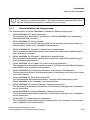
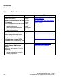
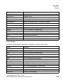
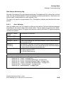
In this Chapter
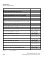
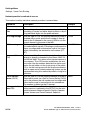
There are the following topics in this chapter:
Thema
Section 1.1, “About this Documentation”
Section 1.2, “Further Information”
Section 1.3, “Basic Functions”
Section 1.4, “Wizard”
Section 1.5, “File Types”
Section 1.6, “File ass_150e.ini”
Section 1.7, “System Requirements”
Section 1.8, “Communication/Access Types”
Section 1.9, “Installing and Uninstalling the Software”
Section 1.10, “Brief Guidelines for Starting Up”
Section 1.11, “Releasing the USB Interface On HiPath 2000 / HiPath OpenOffice EE for Administration”
1.1
About this Documentation
This documentation describes the communication systems HiPath 3800, HiPath 3550,
HiPath 3350, HiPath 3500 and HiPath 3300 and the Real-Time Service Manager
HiPath 5000 RSM that are a part of the HiPath 3000 system family.
HiPath 3000/5000 is also called “the communication system” in this document.
Information on the UC Suite for HiPath 3000 (OpenScape Office HX) can be found in the OpenScape Office V3 documentation.
1-2
A31003-H3590-M100-5-76A9, 11/2011
HiPath 3000 Manager E, Administrator Documentation
intro.fm
Nur für den internen Gebrauch
>
1.1.1
Introduction
About this Documentation
The provided features and the released applications can be different in every country. Therefore, the sales information is the single mandatory document which provides the released features and the hardware for your country.
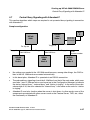
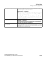
Documentation and target groups
The documentation for HiPath 3000/5000 is intended for different target groups.
●
HiPath 3000/5000 V9, Feature description
This documentation describes all the features of HiPath 3000/5000 and is intended for
sales personnel and customers.
●
HiPath 3000/5000 V9, Getting Started
This documentation is a quick reference guide for the assembly and commissioning of a
communication system and is intended for administrators.
●
HiPath 3000/5000 V9, Manager C, Administrator documentation
This documentation describes administration procedures using HiPath 3000 Manager C
and is directed at customers.
●
HiPath 3000/5000 V9, Manager E, Administrator documentation
This documentation describes administration procedures using HiPath 3000 Manager E
and is directed at administrators.
●
HiPath 3000/5000 V9, HG 1500 V3.0, Administrator documentation
This documentation describes the administration of HG 1500 using Web-Based Management (WBM) and is intended for administrators.
●
HiPath 3000/5000 V9, Configuration Examples, Administrator Documentation
The documentation contains a detailed description of selected service tasks and is intended for administrators.
●
HiPath 3000/5000 V9, Service Documentation
This documentation describes the hardware, assembly and commissioning of the
HiPath 3000/5000 and is intended for service technicians.
●
HiPath 3000/5000 V9, Inventory Manager, Operating Instructions
This documentation describes the operation of the Inventory Manager and is intended for
service technicians.
●
HiPath 3000/5000 V9, Software Manager, Operating Instructions
This documentation describes the operation of the Software Manager and is intended for
service technicians.
●
HiPath 3000, DLI, Administrator documentation
This documentation describes the central administration of IP workpoints via the system
and is intended for service technicians.
A31003-H3590-M100-5-76A9, 11/2011
HiPath 3000 Manager E, Administrator Documentation
1-3
intro.fm
Introduction
About this Documentation
Nur für den internen Gebrauch
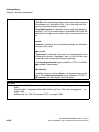
Documentation in the environment of HiPath 3000/5000
Further information for HiPath 3000/5000 can be found in the manuals of the following products:
●
HiPath 3000 V9, myPortal entry Web Services
●
OpenScape Office V3
●
HiPath Xpressions Compact V3
●
Entry VoiceMail
●
OpenStage phones
1-4
A31003-H3590-M100-5-76A9, 11/2011
HiPath 3000 Manager E, Administrator Documentation
intro.fm
Introduction
About this Documentation
Nur für den internen Gebrauch
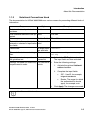
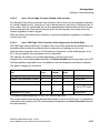
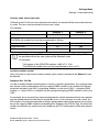
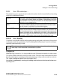
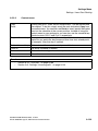
1.1.2
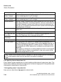
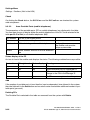
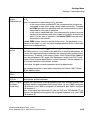
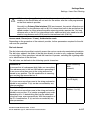
Notational Conventions Used
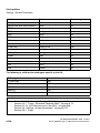
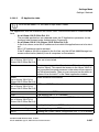
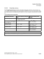
The documentation for HiPath 3000/5000 uses various means for presenting different kinds of
information.
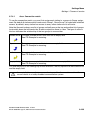
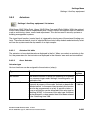
Purpose
Body text that is of particular importance.
Style
Bold
Example
Name must not be deleted.
User interface elements to be op- Bold
erated.
Click OK.
Menu sequence
File -> Close
Bold -> Bold
Text visible in files and text to be Courier and
entered or selected in input/selec- bold
tion fields.
Word1 Word2 Word3
Placeholder
In angle brack- <InstDir>
ets and italic
Files and directories containing
files.
Courier
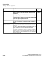
Operations and sub-operations in Numbered,
the guideline text
nested list
<InstDir>/config/services/global.cfg
1.
Settings that need not necessarily List with bullet 2.
be performed in order.
points
3.
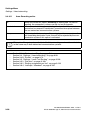
>
Activate the SIP Registrar checkbox.
The input fields are now activated.
Enter the following settings:
1.
Activate the optional Authentication checkbox.
2.
Complete the input fields:
●
SIP - UserID: for example,
hipath3000br13
●
Realm: The range for which
the authentication should
apply, for example, sol.
Click Apply. The changes are saved.
Identifies useful information.
A31003-H3590-M100-5-76A9, 11/2011
HiPath 3000 Manager E, Administrator Documentation
1-5
intro.fm
Introduction
Further Information
1.2
Nur für den internen Gebrauch
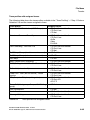
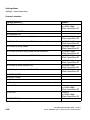
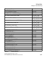
Further Information
Contents
Languages
URL
Product Overview
Product descriptions
German
English
http://opus1.global-intra.net:8080/
TopNet/index.html
Electronic Documentation on SEN
ESY Products
Selection and download of the following:
●
Operating manuals
●
Administrator documentation
●
Service documentation
●
Sales documentation
German
English
French
Italian
Dutch
Portuguese
Spanish
http://apps.g-dms.com:8081/techdoc/
search_de.htm
Expert Wiki
Information about communication
systems, telephones and Unified
Communications
German
English
http://wiki.siemens-enterprise.com
OpenScape Interactive Request
German
and Information System OSIRIS
Knowledge base with questions and
answers on products and solutions
https://osiris.siemens-enterprise.com/
Knowledge Management for Oper- English
ational Support and Services
KMOSS
Platform for provisioning of service
information:
●
Tips &Tricks
●
Service information sorted according to products
https://www.g-dms.com/livelink/
livelink.exe/open/12466438
1-6
A31003-H3590-M100-5-76A9, 11/2011
HiPath 3000 Manager E, Administrator Documentation
intro.fm
Nur für den internen Gebrauch
1.3
Introduction
Basic Functions
Basic Functions
Besides the usual management options provided via the User administration, you can also
manage the communication system via the Settings (a list of the communication systems supported by the program can be obtained via Help/About). The capabilities offered by the program are determined by the Password level.
>
A detailed description of the HiPath 3000/5000 communication system can be found
in the "HiPath 3000/5000, System Reference Manual".
A detailed description of all available features can be found in the manual "HiPath
3000/5000, Feature Description".
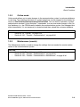
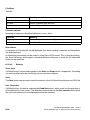
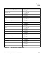
Basic functions
Section 1.3.1, “Read/write database”, on page 1-8
Section 1.3.2, “Online mode”, on page 1-9
Section 1.3.3, “Maintenance (remote)”, on page 1-9
Section 1.3.4, “Security (User administration)”, on page 1-10
Section 1.3.5, “Settings”, on page 1-13
Section 1.3.6, “Password level”, on page 1-13
A31003-H3590-M100-5-76A9, 11/2011
HiPath 3000 Manager E, Administrator Documentation
1-7
intro.fm
Introduction
Basic Functions
1.3.1
Nur für den internen Gebrauch
Read/write database
General Procedure
1.
The configuration of the communication system is read via the menu item File/Transfer/
Communication/Read/write database/System -> PC and is then stored as the customer
database in your PC’s main memory.
2.
This customer database can now be administered using the Settings menu and can also
be stored on the hard disk for later use.
3.
In order to enable the implemented settings, the database is transferred back to the communication system via the menu item PC -> System.
>
The transfer from the PC -> System overwrites all previous communication system
settings.
Delta mode
When Delta mode is activated, only changes made since the customer database was last
downloaded are written to the communication system. If, for example, only a station name is
changed, then the transmission time is drastically reduced.
To determine the delta data, the program compares the loaded customer database with the file
lastload.kds, which is automatically created after every transfer from the System -> PC and
is stored on the hard disk.
See also:
–
–
1-8
Section 8.19, “Transfer”, on page 8-25
Section 8.19.1, “Transfer | Communication”, on page 8-26
A31003-H3590-M100-5-76A9, 11/2011
HiPath 3000 Manager E, Administrator Documentation
intro.fm
Nur für den internen Gebrauch
1.3.2
Introduction
Basic Functions
Online mode
Online mode allows you to make changes to the communication system´s customer database
in real time. The operating elements of a system telephone can be mapped on the display terminal via File/Transfer/Communication/Online/Online. You use these to emulate a system
administration terminal. Using Assistant T commands, you can now make changes to the "active" database, i.e., the CDB currently loaded in the communication system. Your changes take
effect immediately. It is not necessary to download and then upload the customer database.
See also:
–
–
Section 8.19, “Transfer”, on page 8-25
Section 8.19.1, “Transfer | Communication”, on page 8-26
1.3.3
Maintenance (remote)
The Maintenance facility is used to change the settings that are needed for remote maintenance of the communication system.
See also:
–
–
–
Section 8.19, “Transfer”, on page 8-25
Section 8.19.1, “Transfer | Communication”, on page 8-26
Section 8.19.2, “Transfer | Communication | Maintenance”, on page 8-36
A31003-H3590-M100-5-76A9, 11/2011
HiPath 3000 Manager E, Administrator Documentation
1-9
intro.fm
Introduction
Basic Functions
1.3.4
Nur für den internen Gebrauch
Security (User administration)
User administration
The access parameters between the program and the communication system are defined via
the user administration (File/Transfer/Communication/Security/User administration). Up to
16 users (= administrators) can be entered. A user is identified by his or her name. The establishment of a user group defines the usage rights of the respective user. Authentication is carried out by means of a password.
Two user names and the user groups linked to them, which are relevant for the administration,
are preset in the default setting of the user administration:
–
User name “31994” with the user group “Service”
As long as no other user groups are set up, this user group has the access rights to all
administrable system data and the execute rights for all actions available in the system.
Excluded from this are access rights that are reserved for development (see user
group “Development”).
–
User name “633423” or “office” with the user group “Customer”
The user group ‘Customer’ has access to all data that is intended for administration by
the customer (see also further below).
–
User name “*95” with the user group “none”
As long as no other user groups other than the one described above are set up, it is
possible to administer customer-relevant data using the telephone with this user group
(due t o compatibility reasons with Hicom 150 E Office Rel. 1.0). This entry has no
meaning for the communication system administration with HiPath 3000 Manager.
User access rights can be determined by specifying one of the 6 user groups available.
–
User group <none>
This user group has no meaning when using the program for administration.
–
The user group User admin
This user group has the access rights to the User administration dialog, where the
user and the linked user groups are set up.
–
The user group Revision
This user group has the access rights to the Security protocol dialog.
–
User group Service
By default, only the user “31994” exists (see further below).
–
The user group Administration (Customer)
By default, only the user “633423” exists (see further above).
This user group can access data that is intended for administration by the customer.
This customer data can, however, also be additionally set up by the service. An exception is the confidential customer data, which may be handled only by the customer:
1-10
A31003-H3590-M100-5-76A9, 11/2011
HiPath 3000 Manager E, Administrator Documentation
intro.fm
Nur für den internen Gebrauch
Introduction
Basic Functions
–
PIN code (only relevant for administration on the system telephone)
–
Individual speed dialing facility (only relevant for administration on the system telephone)
–
Contents of the name keys of system telephones
–
Central speed dial destinations
–
Call charge data per station and per line
–
The user group Call charges
has the access rights to the data from call detail recording, call charge data records
and the call detail counter. If this user group is not set up, the rights belong to the customer user group. If the customer is not set up either, they belong to the service user
group.
–
User group Development
In addition to the access rights of the service user group, the Development user group
has the possibility of administering additional data in the communication system.
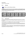
Security protocol (log)
A distinction is made in the security protocol (log) between:
– Offline mode
– Online mode, Active logging
– Online mode, Logging not active
The protocol mode is selected via a dialog.
Offline mode
In offline mode, only the existing archive file can be opened, viewed and printed. The archive
files cannot be modified. There is no connection with a communication system, so the archive
information from the communication system cannot be displayed.
Online mode, Active logging
A connection to the communication system is set up for online mode. In order to use this mode
with active logging, the logging facility in the communication system must actually be active (determined by the hardware configuration).
If logging has already been executed, the archive information from the communication system
is also displayed. The archive file name is taken from the communication system and an attempt is made to open this file and to display the archive information it contains. The archive
information from the communication system and from the archive file are normally identical.
A31003-H3590-M100-5-76A9, 11/2011
HiPath 3000 Manager E, Administrator Documentation
1-11
intro.fm
Introduction
Basic Functions
Nur für den internen Gebrauch
Online mode, Logging not active
A connection to the communication system is set up for online mode. In order to use this mode
with inactive logging, the logging facility in the communication system must not be active (determined by the hardware configuration).
See also:
–
–
–
–
1-12
Section 8.19, “Transfer”, on page 8-25
Section 8.19.1, “Transfer | Communication”, on page 8-26
Section 8.19.36, “Security | User administration”, on page 8-101
Section 8.19.37, “Security | Protocol”, on page 8-103
A31003-H3590-M100-5-76A9, 11/2011
HiPath 3000 Manager E, Administrator Documentation
intro.fm
Nur für den internen Gebrauch
1.3.5
Introduction
Basic Functions
Settings
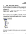
The Settings option is used to administer the customer database currently loaded in the program.
In order to enable the implemented settings, the customer database is transferred to the communication system via the menu item File | Transfer | Communication | Read/write database | PC
-> System .
See also:
–
–
–
Chapter 7, “Station view”
Chapter 9, “Settings Menu”
Chapter 10, “System-wide”
1.3.6
Password level
The password level determines the administration options of the CDB or the communication
system.
The identification and authentication procedure has been altered significantly as of Hicom 150
E Office Rel. 2.
–
Up to and including Hicom 150 E Office Rel. 1.0
The entered code for starting the program is immediately verified (against the passwords specified for the program). The user is then assigned the corresponding rights.
The user name is not used.
–
As of Hicom 150 E Office Rel. 2.0
The user name and password are checked against the customer database or the communication system. This means that the user name and password can only be entered
here; the check, however, is only implemented after call setup or when a customer database has been opened.
See also:
–
–
Section 1.3.4, “Security (User administration)”, on page 1-10
Section 12.2, “Password Level”, on page 12-14
A31003-H3590-M100-5-76A9, 11/2011
HiPath 3000 Manager E, Administrator Documentation
1-13
intro.fm
Introduction
Wizard
1.4
Nur für den internen Gebrauch
Wizard
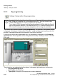
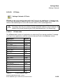
The Wizard provides a guided dialog for entering the most important customer data. The customer data that is needed for an initial startup is collected here and then transferred to the customer database (CDB) of the communication system. Please note, however, that the Wizard
only collects the most important customer data that is needed for a fast startup. Detailed entries
can be processed later in HiPath 3000 Manager.
The Wizard can be started with Tools | Run Wizard (for HiPath 3000) or with Tools | Run S0
Wizard (HiPath 500).
>
The Wizard can also be run more than once. Note that in such cases, the currently
loaded CDB is taken into account in the Wizard. In other words, all features which
were set up later using HiPath 3000 Manager and which are not handled via the dialogs of the Wizard are retained.
Follow the instructions given in the user interface after you have started the Wizard.
After the Wizard has been run, you can optionally carry out additional settings in the HiPath
3000 Manager in order to optimize your communication system to suit your purposes.
Once you have modified the customer data, you still must transfer it to the communication system. On completion of this step, the communication system is ready for operation.
1-14
A31003-H3590-M100-5-76A9, 11/2011
HiPath 3000 Manager E, Administrator Documentation
intro.fm
Nur für den internen Gebrauch
1.5
Introduction
File Types
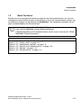
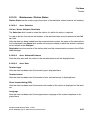
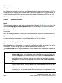
File Types
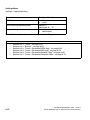
The following types of files exist:
–
*.cdb, Customer database
–
*.fst, Application Processor System (APS)
As of Hicom 150 E Office Rel. 2.2:
–
*.lng, Loadable texts (languages)
–
*.net, NET files, Central Database for networked systems on the HiPath 5000 server
The program tool will not recognize files with other extensions as databases.
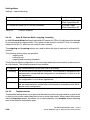
Topic
Section 1.5.1, “Customer database (CDB)”, on page 1-16
Section 1.5.2, “Application Processor System (APS) and loadable texts (languages)”, on page
1-16
A31003-H3590-M100-5-76A9, 11/2011
HiPath 3000 Manager E, Administrator Documentation
1-15
intro.fm
Introduction
File Types
1.5.1
Nur für den internen Gebrauch
Customer database (CDB)
The customer database (CDB) contains all customized settings of the communication system.
You can use the HiPath 3000 Manager to edit the CDB. The CDB data is generated on your PC
in a file with the extension *.kds and then transferred to the communication system when you
are done editing.
After selecting the software version (Version) and the system type (Expansion), a new empty
CDB can be created via File/New. The individual cards are configured via System Status/
Cards.
>
Please note that the CDB should always be first transferred from the communication
system. This ensures that the data that you edit always reflects the current status.
Nevertheless, you should still save the CDB on a data medium just to be on the safe
side.
See also:
–
–
–
Section 1.3.1, “Read/write database”, on page 1-8
Section 1.5, “File Types”, on page 1-15
Chapter 8, “File Menu”
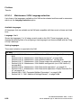
1.5.2
Application Processor System (APS) and loadable texts
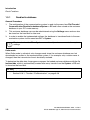
(languages)
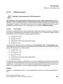
Load APS texts is used for exchanging variable texts in the following existing files:
–
*.fst, APS transfer over HiPath 3000 Manager
–
*.fli, APS transfer over TFTP (TCP/IP)
–
*.fls, APS transfer over TFTP (TCP/IP) with Office One
–
*.b01, Programming a flash card
–
*.mmc, Programming a multimedia chip
See also:
–
1-16
Section 1.5, “File Types”, on page 1-15
A31003-H3590-M100-5-76A9, 11/2011
HiPath 3000 Manager E, Administrator Documentation
intro.fm
Nur für den internen Gebrauch
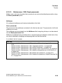
1.6
Introduction
File ass_150e.ini
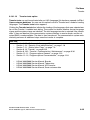
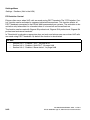
File ass_150e.ini
The ass_150e.ini file is stored in the folder C:\Documents and Settings\<user>\Application
Data\Siemens\Manager E. <user> indicates the login of the registered user on the PC. The
file can be edited with an editor (such as Notepad).
You can change the listed modem types and also add further modems via this file. A new modem can be added under [Modem_6], for example, if the entries [Modem_1] to [Modem_5] already exist. The same applies to the [ModemString_x] entry for the ”system modem”.
If desired, you can use the file ass_150e.ini to specify or change the default editor to be used
when displaying or editing the maintenance data, for example. You can enter any desired editor
that is available on your system as the editor.
As of V5.0, the IP address of the CLA host for licensing is also specified in the ass_150e.ini file
(see also Section 9.11, “Settings | Licensing”, on page 9-336).
>
When updating the application, you will be asked whether or not the file ass_150e.ini
should be overwritten. If you respond with Yes, the file asse_150e.ini will be overwritten, and the old asse_150e.ini file will be saved under the name asse_150e.old.
Consequently, if you have changed the parameters for the modems, for example,
you should copy the modem parameters from the ass_150e.ini (asse_150e.old) file
to the new ass_150e.ini.
Similarly, if you have changed the settings for the column widths in the tables, for
example, and want to use these settings in the new version, you will need to copy
the [Desktop] section from the old ass_150e.ini (asse_150e.old) file to the new
ass_150e.ini file.
A31003-H3590-M100-5-76A9, 11/2011
HiPath 3000 Manager E, Administrator Documentation
1-17
intro.fm
Introduction
System Requirements
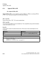
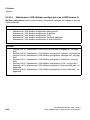
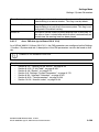
1.7
Nur für den internen Gebrauch
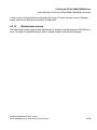
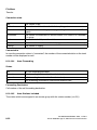
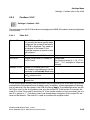
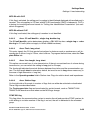
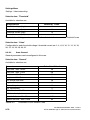
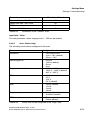
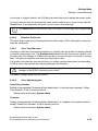
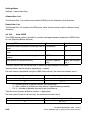
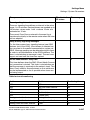
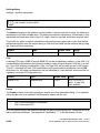
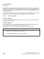
System Requirements
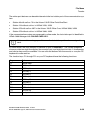
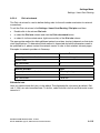
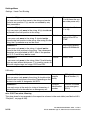
The following minimum requirements must be met for the program to operate successfully:
Computer
depends on operating system requirements
RAM
at least 512 MB
Hard disk memory
300 Mbytes free
Operating system
Windows Vista (32 and 64 Bit), Windows NT, Windows 2000,
Windows XP, Windows 2003
1.8
Communication/Access Types
The HiPath 3000 Manager supports the following communication/access types:
●
Serial
●
Analog modem
●
S0
●
IP
1-18
A31003-H3590-M100-5-76A9, 11/2011
HiPath 3000 Manager E, Administrator Documentation
intro.fm
Nur für den internen Gebrauch
1.9
Introduction
Installing and Uninstalling the Software
Installing and Uninstalling the Software
Installation
1.
Insert the installation CD into your CD-ROM drive.
If your CD-ROM drive is configured with an Autostart function, the CD menu will open automatically. If the CD menu does not open automatically, select Start | Run and then use
the Browse button to find and execute the file
<CD-drive>:\setup.exe.
2.
Select the menu item Installation from the CD menu.
3.
Then select the menu item HiPath 3000 Manager from the following menu.
4.
This starts up the installation wizard. Follow the instructions on the screen to complete the
installation.
5.
When the procedure has finished, you are notified that the installation has been successfully performed.
Confirm the message with the OK button.
The program has been installed.
Uninstallation
1.
First close/exit the HiPath 3000 Manager (if not already closed).
2.
Select Start | Settings | Control Panel.
3.
Double-click the Software symbol in the Control Panel window.
4.
Select the "HiPath 3000 Manager" entry in the list of installed programs and click the Add/
Remove button.
5.
Confirm the security prompt with the Yes button.
6.
The program data is now removed from your PC.
Wait for this procedure to be completed.
7.
When the procedure has finished, you are notified that uninstallation has been successfully
performed.
Confirm the message with the OK button.
The program has been uninstalled.
A31003-H3590-M100-5-76A9, 11/2011
HiPath 3000 Manager E, Administrator Documentation
1-19
intro.fm
Introduction
Brief Guidelines for Starting Up
1.10
Nur für den internen Gebrauch
Brief Guidelines for Starting Up
The following steps are needed to start up the communication system:
●
Install communication system (by authorized service personnel)
●
Connect terminals
●
Connect PCs to communication system (e.g., via serial interface)
●
Start the CD included in the delivery and install HiPath 3000 Manager on the PC
●
Start HiPath 3000 Manager
●
Transfer CDB from the communication system to the PC (File | Transfer)
●
Optimize CDB in HiPath 3000 Manager
– Configure station (Settings | Set up station, Station or Stationview)
– Configure lines (Settings | Lines/networking, Lines and Routes)
– Swapping/Replacing Languages, if necessary (File | Transfer, Loadable texts)
●
Print out label sheets for system telephone(s) (e.g., optiPoint 500)
(Settings | Set up station, Key programming, Labeling )
●
Save CDB (File | Save customer database as)
●
Transfer CDB from the PC back to the communication system (File | Transfer)
1-20
A31003-H3590-M100-5-76A9, 11/2011
HiPath 3000 Manager E, Administrator Documentation
intro.fm
Introduction
Releasing the USB Interface On HiPath 2000 / HiPath OpenOffice EE for Administration
Nur für den internen Gebrauch
1.11
Releasing the USB Interface On
HiPath 2000 / HiPath OpenOffice EE for Administration
On system start-up the USB interface on HiPath 2000 / HiPath OpenOffice EE is in CLI mode
(CLI: Command Line Interface). In order to perform HiPath 3000 Manager HiPath 2000/
HiPath OpenOffice EE administration via USB, the system interface must be enabled via CLI.
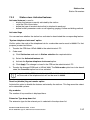
This requires the following steps:
1.
Connect the PC and HiPath 2000/HiPath OpenOffice EE via a USB cable
2.
If the USB driver HiPath 2000/HiPath OpenOffice EE Gateway is not yet installed on the
PC, you must first configure the driver. Once you have plugged in the USB cable, Windows
finds the new hardware, and the new interface must be installed with the USB driver. The
USB driver is provided on the HiPath 2000/HiPath OpenOffice EE system CD (usb.inf/
usb.sys)
3.
Determine the COM interface (e.g., COM 3) for the USB port. To do so, start the Device
Manager under My Computer | Properties | Hardware . Under Ports (COM and LPT), you
can view the number of the COM interface of the HiPath 2000/ HiPath OpenOffice EE
Gateway
4.
Use the "Hyperterminal" program to set up a connection to HiPath 2000/
HiPath OpenOffice EE and enable the USB interface of HiPath 2000 /HiPath OpenOffice
EE. Once the USB interface is enabled via CLI, HiPath 2000/ HiPath OpenOffice EE enables this interface for V.24 operation. To do this:
–
Enter any character
–
Log on using your user name and password (31994/…)
–
Obtain write access using the command "get write access"
–
Enable the USB interface using the command "release usb", and confirm with "y" (yes)
To revert to CLI functionality on HiPath 2000/HiPath OpenOffice EE, a reset must be carried
out on HiPath 2000/HiPath OpenOffice EE.
In order to connect HiPath 3000 Manager via USB with HiPath 2000/HiPath OpenOffice EE, select under Options | Program options | Communication USB as the interface, and select the
COM port of the USB driver (the baud rate settings are not relevant for USB). In the Transfer
dialog, select Direct access.
A31003-H3590-M100-5-76A9, 11/2011
HiPath 3000 Manager E, Administrator Documentation
1-21
intro.fm
Introduction
Nur für den internen Gebrauch
Releasing the USB Interface On HiPath 2000 / HiPath OpenOffice EE for Administration
1-22
A31003-H3590-M100-5-76A9, 11/2011
HiPath 3000 Manager E, Administrator Documentation
usage.fm
Nur für den internen Gebrauch
2
Operation
Operation
This chapter is intended to familiarize you with the operation of HiPath 3000 Manager.
Contents of this chapter
Section 2.1, “Program Window”, on page 2-2
Section 2.1.1, “Menu bar”, on page 2-4
Section 2.1.2, “Toolbar”, on page 2-5
Section 2.1.3, “System View/Net View and Station View”, on page 2-7
Section 2.1.4, “Administration area”, on page 2-9
Section 2.1.5, “Status bar”
Section 2.2, “Copying and Deleting Entries (Drag & Drop)”, on page 2-11
Section 2.3, “Context Menu”, on page 2-12
Section 2.4, “Table Handling”, on page 2-13
Section 2.5, “Invoking Help”, on page 2-15
A31003-H3590-M100-5-76A9, 11/2011
HiPath 3000 Manager E, Administrator Documentation
2-1
usage.fm
Operation
Program Window
2.1
Nur für den internen Gebrauch
Program Window
After you start HiPath 3000 Manager and log on successfully (see Chapter 3, “ Start and Logon”), the program window appears. The display is optimized for a screen resolution of
1024 x 768 pixels.
The information that is displayed in the separate areas of the program window can differ, depending on the program status.
The following representation of the user interface gives an example of the program window. The
exact display depends on the hardware components in use. The display in your program window may therefore differ.
selected CDB
Menu bar
System-/Stationview
Figure 2-1
2-2
Toolbar
Administration area
Status bar
The Program Window
A31003-H3590-M100-5-76A9, 11/2011
HiPath 3000 Manager E, Administrator Documentation
usage.fm
Nur für den internen Gebrauch
Operation
Program Window
In the program window you will find:
Menu bar
Toolbar
System View/Net View and Station View
Administration area
Status bar
A31003-H3590-M100-5-76A9, 11/2011
HiPath 3000 Manager E, Administrator Documentation
2-3
usage.fm
Operation
Program Window
2.1.1
Nur für den internen Gebrauch
Menu bar
The functions of HiPath 3000 Manager can be accessed via the menu bar. When you click the
left mouse button on one of the menu items, the menu opens, and you can then select the functions.
The following items can be found on the menu bar:
File Menu
Settings Menu
System Status Menu
Tools Menu
Options Menu
Options Menu
Help Menu
>
2-4
An overview of the menus can be found in Chapter 6, “Menu Overviews”.
A31003-H3590-M100-5-76A9, 11/2011
HiPath 3000 Manager E, Administrator Documentation
usage.fm
Nur für den internen Gebrauch
2.1.2
Operation
Program Window
Toolbar
You can use the toolbar to start important functions directly and quickly; these functions are
also available on the menu bar. Some icons allow you to reach other functions if you click the
triangle to the right of the icon.
The following items can be found on the toolbar:
(from left to right)
New
Open Customer Database
Close Customer Database
Save Customer Database
Transfer
Transfer | HiPath 5000 RSM/AllServe Server
Settings | Netwide Data
Settings | Set up station
Settings | Cordless (Not in the USA)
Settings | Lines/networking
A31003-H3590-M100-5-76A9, 11/2011
HiPath 3000 Manager E, Administrator Documentation
2-5
usage.fm
Operation
Program Window
Nur für den internen Gebrauch
The following items can be found on the toolbar:
(from left to right)
Settings | Least Cost Routing
Settings | Incoming calls
Settings | Classes of service
Settings | Network
Settings | System Parameters
Settings | Auxiliary equipment
Call charges
System-wide
Help Topics
>
2-6
An overview of the menus can be found in Chapter 6, “Menu Overviews”.
A31003-H3590-M100-5-76A9, 11/2011
HiPath 3000 Manager E, Administrator Documentation
usage.fm
Nur für den internen Gebrauch
2.1.3
Operation
Program Window
System View/Net View and Station View
The configuration of the communication system occurs via the System, Net and Station views.
The system view shows the configuration from the viewpoint of the hardware / boards. If a network CDB has been loaded, the system view changes to the net view and includes all systems
of the network. The station view can be used to obtain a quick overview of all configured stations. You can optionally switch between the various views by using the Systemview, Netview
and Stationview buttons.
You can scale the width of the views area freely, even to the extent of making it completely invisible. To adjust the size, proceed in the same way as described for changing the column width
in tables (see Section 2.4, “Table Handling”, on page 2-13).
System View and Net View
The system/net view includes navigation trees for all opened CDBs. The navigation tree provides you with quick access to the menu functions Settings and System Status (see also Section 2.1.1, “Menu bar”, on page 2-4). You can expand or collapse individual branches of the tree
by clicking the + or - symbol before the relevant entries in the navigation tree. For each opened
CDB, a separate branch is created in the navigation tree. When a network CDB is loaded, the
branches for each CDB are initially collapsed.
Station view
The station view contain a table (station selection) with the call numbers and names of all stations. If a network CDB is loaded, the station view includes all stations in the network. Inactive
stations are shown in gray. In the case of groups, a group icon is additionally displayed before
the station name.
A31003-H3590-M100-5-76A9, 11/2011
HiPath 3000 Manager E, Administrator Documentation
2-7
usage.fm
Operation
Program Window
Nur für den internen Gebrauch
You can select a station via the Station selection. The station parameters for the selected station are displayed in the right window pane (see also Section 7.2, “Station Parameters”, on
page 7-3). The stations are sorted in ascending or descending order by one of the columns
(Call no. or Name). You can change the sorting order by clicking the column headers.
The Search no. and Search Name fields/drop-down lists can be used to find a particular station. To do this, enter a call number or a name in the fields or select an entry from the dropdown lists. As you enter each character, the first (or closest) hit in the table is highlighted and
can be made visible by moving the table. In this case, the table is automatically sorted in ascending order by the call number or name. On pressing the Enter key, the highlighted station is
selected, and the station parameters/details for that station are displayed in the right window
pane.
Due to system restrictions, not all parameters in the station view can be set for the selected
station. This applies, in particular, to the call numbers, groups and forwarding. The arrow symbol on the right next to each parameter enables you to directly access the dialog box in which
the corresponding parameter can be set.
2-8
A31003-H3590-M100-5-76A9, 11/2011
HiPath 3000 Manager E, Administrator Documentation
usage.fm
Operation
Program Window
Nur für den internen Gebrauch
2.1.4
Administration area
The Administration area displays the dialogs in which settings for the communication system
can be made. A detailed list of the communication systems supported by HiPath 3000 Manager
can be found by selecting Help/About...).
Tabs bar
Button bar
Tabs bar
The tabs can be used to switch between the dialogs of the respective functions. You can also
open the individual tabbed pages directly via the Toolbar (see also Section 2.1.2, “Toolbar”, on
page 2-5) or the Navigation tree (see Section 2.1.3, “System View/Net View and Station View”,
on page 2-7).
A31003-H3590-M100-5-76A9, 11/2011
HiPath 3000 Manager E, Administrator Documentation
2-9
usage.fm
Operation
Program Window
Nur für den internen Gebrauch
Button bar
Button
Description
Reset
Discards the changes and restores the settings to the applicable values on
calling up the dialog box.
Apply
Accepts the changes into the opened CDB. Note that the changes will only
take effect in the communication system after the CDB has been transferred back to the system.
Help
Displays the help text for the open dialog.
>
2-10
To avoid data loss, especially in cases where you have made many changes, you
should also use the File/Save customer database or File/Save customer database as function to ensure that your changes are also written to the file.
A31003-H3590-M100-5-76A9, 11/2011
HiPath 3000 Manager E, Administrator Documentation
usage.fm
Nur für den internen Gebrauch
2.1.5
Operation
Copying and Deleting Entries (Drag & Drop)
Status bar
The status bar provides you with additional brief information on the status of HiPath 3000 Manager.
The status bar consists of 4 areas:
Area
Description
Info
This area is used to display program messages and additional information,
e.g., on the selected function.
CAPS
Status of Caps Lock key
NUM
Status of the Num Lock key
2.2
Copying and Deleting Entries (Drag & Drop)
You can copy and delete entries easily by using the “drag & drop” technique (“click and drag”):
1.
To do this, first click on any entry that you want to copy or delete by using the left mouse
button.
2.
You can now drag the entry while holding down the left mouse button to the field to which
it is to be copied.
3.
To delete the contents of a field, drag and drop the entry onto the icon for the Recycle Bin.
A31003-H3590-M100-5-76A9, 11/2011
HiPath 3000 Manager E, Administrator Documentation
2-11
usage.fm
Operation
Context Menu
2.3
Nur für den internen Gebrauch
Context Menu
If you right-click certain areas in the windows (e.g., in tables), a context menu appears with different menu items that are suited to the current situation. Two sample context menus are described below.
Example Context menu in tables
Delete
Marked areas are deleted.
Copy
Marked areas are copied to the clipboard.
Paste
Marked areas are pasted from the clipboard into the table.
Sort ascending
The table is sorted in ascending order according to the marked column.
Sort descending
The table is sorted in descending order according to the marked column.
Sort logical
Sorting as with the older Hicom Assistant versions.
Example Context menu in key programming
Delete
The selected key of all selected stations is cleared.
Clear all
All keys of all selected stations are cleared.
Copy
The currently selected key of the selected station is copied.
Copy all
All keys of the selected station are copied.
Paste
For all marked terminals, the keys copied earlier are copied over to the
currently selected station. Multiple stations may be selected (using the
Shift or Ctrl key).
Fill/Delete:
The dialog will offer options for filling in the keys (only for busy lamp
fields).
2-12
A31003-H3590-M100-5-76A9, 11/2011
HiPath 3000 Manager E, Administrator Documentation
usage.fm
Nur für den internen Gebrauch
2.4
Operation
Table Handling
Table Handling
All tables are handled in the same way when changing entries or the appearance of the table.
Changing entries in tables
1.
Use the left mouse button to select the field to be changed (click the field).
2.
Place the mouse pointer at the entry you want to change and enter the changes. The previous contents are retained.
3.
Click the Apply button.
or
1.
Use the left mouse button to click twice on the field to be changed (double-click the field).
2.
Enter the changes. The previous contents are completely overwritten.
3.
Click the Apply button.
>
The table entries in some tables cannot be changed.
Sorting tables
1.
With the left mouse button, click the header of the column that you want to use for sorting
the table. The table can be sorted via the header in ascending, descending and partly in
logical order.
or
1.
Click the header of the column that you want to use for sorting the table. The column is
selected.
2.
With the right mouse button, click on the selected column (right-click the selected column).
The context menu is displayed.
3.
Select the type of sorting from the context menu.
>
Some tables cannot be sorted.
Due to the sorting of the table, it is conceivable that important table entries may only
appear at the end of the table.
The sorting method applies to the relevant table regardless of the opened CDB and
remains in effect even after exiting HiPath 3000 Manager.
A31003-H3590-M100-5-76A9, 11/2011
HiPath 3000 Manager E, Administrator Documentation
2-13
usage.fm
Operation
Table Handling
Nur für den internen Gebrauch
Changing column width
1.
In the table header, guide the mouse pointer over the column marking to the right of the
column whose width you want to change (or between two columns). The mouse pointer
changes to a column identifier.
2.
Click the left mouse button. While holding the mouse button down, drag the mouse to the
right or left to change the column width.
3.
You can also use this function on several columns at once. To do this, select several columns with the "Shift" key and the left mouse button. Click the header.
2-14
A31003-H3590-M100-5-76A9, 11/2011
HiPath 3000 Manager E, Administrator Documentation
usage.fm
Nur für den internen Gebrauch
2.5
Operation
Invoking Help
Invoking Help
HiPath 3000 Manager offers you multiple ways to invoke help.
●
If you want to start the help without starting HiPath 3000 Manager, select Start/Programs/
HiPath 3000 Manager/HiPath 3000 Manager Help.
Alternatively,
●
you can start the help from within HiPath 3000 Manager via Help/Help contents or via the
Help icon in the toolbar.
Context-sensitive help
HiPath 3000 Manager assists you in the process of editing settings by means of a context-sensitive help.
●
Press the F1 key on your keyboard to obtain specific help on the current tab/dialog.
or
●
Click the Help button from within the current tabbed page or dialog box.
In addition, brief information is also displayed in the status bar (see Section 2.1.5, “Status bar”,
on page 2-11).
A31003-H3590-M100-5-76A9, 11/2011
HiPath 3000 Manager E, Administrator Documentation
2-15
usage.fm
Operation
Invoking Help
2-16
Nur für den internen Gebrauch
A31003-H3590-M100-5-76A9, 11/2011
HiPath 3000 Manager E, Administrator Documentation
start.fm
Nur für den internen Gebrauch
3
Start and Log-on
Logging on to Manager E
Start and Log-on
Start the HiPath 3000 Manager using:
Start/Programs/HiPath 3000 Manager/HiPath 3000 Manager.
>
If you are using Windows NT/2000, please note that the access rights of the current
account may not be sufficient.
The HiPath 3000 Manager administration program must be started under an account
that has the appropriate system access rights.
If you are not sure about your access rights, contact your system administrator.
3.1
Logging on to Manager E
The Log-on window is displayed on starting the program.
1.
To log on, enter your User name and Password in the corresponding input fields (when
logging on for the first time, enter the default user name “31994” and the default password
“31994”). More details on user names and passwords can be found in Section 1.3.4, “Security (User administration)”, on page 1-10 and Section 1.3.6, “Password level”, on page
1-13.
2.
Confirm the entries with the OK button.
3.
The Program window is displayed. The contents of the window depend on the configuration
of your communication system.
>
If you have already created a password, use it. You can change the password later
at any time via Options/Change password. When entering your password, note
that it is case-sensitive!
A31003-H3590-M100-5-76A9, 11/2011
HiPath 3000 Manager E, Administrator Documentation
3-1
start.fm
Start and Log-on
Logging on to Manager E
3-2
Nur für den internen Gebrauch
A31003-H3590-M100-5-76A9, 11/2011
HiPath 3000 Manager E, Administrator Documentation
allserve.fm
Nur für den internen Gebrauch
4
Starting up HiPath 5000 RSM/AllServe
Starting up HiPath 5000 RSM/AllServe
A networked system consists of a server (HiPath 5000 RSM/AllServe) and one or more nodes
(HiPath 3000).
The nodes are linked with the server via the IP customer network. The server is the central access for administering the network and the nodes.
The networked system administration includes the setup of the nodes and the HG 1500 cards
inserted in the nodes as well as the server (Feature Server). The node is administered via HiPath 3000 Manager. The server is the central and only administration interface in the networked
system.
>
The nodes form a logical system. The passwords for the Service user range must
be identical in all nodes. The Service user range class of service is required for accessing the server and modifying consistent netwide data.
The nodes are first configured offline (prepared for the networked system). The server is then
set up and the file transfer operation is started. In the course of file transfer, the node is registered at the server, and the node data is imported by the server. Future administrative tasks at
the node will be performed from the server.
>
The software version of the notes must be checked before setup. This system may
only be started up if the current software version is installed in all nodes. Similarly,
the software and the firmware version of HG 1500 must be checked and updated to
the latest version.
In addition, the software versions of the server and HiPath 3000 Manager must be
identical.
Contents of this chapter
Abschnitt 4.1, “Starting up a New HiPath 5000 RSM/AllServe System”
Abschnitt 4.2, “Administering an Existing HiPath 5000 RSM/AllServe System”
Abschnitt 4.3, “Settings for optiClient Attendant”
Abschnitt 4.4, “Information on Inter-system Busy Signaling”
Abschnitt 4.5, “Configuring Stations for the Use of Non-Voice Services”
Abschnitt 4.6, “Parameterizing for Media PC Streaming 1.0 (not in the USA)”
Abschnitt 4.7, “Central Busy Signaling with Attendant P”
A31003-H3590-M100-5-76A9, 11/2011
HiPath 3000 Manager E, Administrator Documentation
4-1
allserve.fm
Starting up HiPath 5000 RSM/AllServe
Starting up a New HiPath 5000 RSM/AllServe System
4.1
Nur für den internen Gebrauch
Starting up a New HiPath 5000 RSM/AllServe System
Topic
–
–
–
–
–
–
–
–
–
–
4.1.1
Abschnitt 4.1.1, “Creating the server”
Abschnitt 4.1.2, “Adding nodes”
Abschnitt 4.1.3, “Setting up the HiPath IP address (HIP)”
Abschnitt 4.1.4, “Configuring netwide call numbers”
Abschnitt 4.1.5, “Assigning HG 1500 channels to the last route and assigning
the protocol”
Abschnitt 4.1.6, “Assigning routing parameters to HG 1500 trunks”
Abschnitt 4.1.7, “Configuring LCR”
Abschnitt 4.1.8, “Setting up a server IP address and node ID”
Abschnitt 4.1.9, “Restarting the server service”
Abschnitt 4.1.10, “Logging on the HG 1500 card”
Creating the server
If a networked system does not yet exit, it can be created with File (offline generation).
1.
Configure the server via:
File | HiPath 5000 RSM/AllServe | New | HiPath 5000 RSM/AllServe Server
The New Server dialog box appears.
2.
Enter the name of the server in the Name field.
3.
Click the Finish button.
A new empty Server NET file is created.
7
4-2
Warning:
This generation of a HiPath 5000 RSM/AllServe server CANNOT be loaded on a
running HiPath 5000 server.
To do this, proceed as follows:
– Power up HiPath 5000 without the respective system CDB
– Use File | HiPath 5000 RSM/AllServe | Transfer | HiPath 5000 RSM/
AllServe Server and the Server->Manager button to transfer the HiPath
5000 to HiPath 3000 Manager
– Add a new node via File | HiPath 5000 RSM/AllServe | New | HiPath 3000/
AllServe Node
A31003-H3590-M100-5-76A9, 11/2011
HiPath 3000 Manager E, Administrator Documentation
allserve.fm
Nur für den internen Gebrauch
4.1.2
Starting up HiPath 5000 RSM/AllServe
Starting up a New HiPath 5000 RSM/AllServe System
Adding nodes
Once setup is complete, individual nodes can be added to the server.
1.
To add a new node, select:
File | HiPath 5000 RSM/AllServe | New | HiPath 3000/AllServe Node
The Enter Source dialog box appears.
2.
Select the required source.
The following source options are available:
– Customer database file
CDB is loaded from a local drive
– Create offline
CDB is generated offline
– Direct load from system
Transfer dialog is started
3.
Click Next.
The Enter node data dialog box appears.
4.
Enter the node data.
5.
Click the Finish button.
The node is created.
>
Reboot the system if a new node has been added to HiPath 5000 RSM.
>
To add the new node on a running HiPath 5000 server, proceed as follows:
– Select: File | HiPath 5000 RSM/AllServe | Transfer | HiPath 3000/
AllServe Node
The Transfer dialog box appears.
– Click the Add node button.
4.1.3
Setting up the HiPath IP address (HIP)
1.
Load the node CDB.
2.
Select Settings | Network.
3.
Select the HIP protocol from the IP-Access drop-down list in the Basic settings tab.
4.
Enter the IP address and the Subnet mask in the areas LAN interface and PSTN interface.
A31003-H3590-M100-5-76A9, 11/2011
HiPath 3000 Manager E, Administrator Documentation
4-3
allserve.fm
Starting up HiPath 5000 RSM/AllServe
Starting up a New HiPath 5000 RSM/AllServe System
Nur für den internen Gebrauch
The HG 1500 card is integrated in the LAN. The system administrator of the relevant LAN provides the necessary information.
>
4.1.4
For Routing, the IP address of the HG 1500 card should be entered as the gateway.
Configuring netwide call numbers
To configure netwide call numbers, every node should be assigned to a defined call number
range. For node 1, e.g., one thousand call numbers (1001, 1002, etc.), for node 2, e.g., two
thousand call numbers (2000, 2001, etc.), etc.
Please note that all call numbers and codes (trunks, internal accesses, groups, etc.) are unique
in all individually generated systems. The unique numbering of all systems belonging to the networked system must therefore be defined before the system is generated.
4.1.5
Assigning HG 1500 channels to the last route and assigning
the protocol
Assigning HG 1500 channels to the last route
All HiPath HG 1500 channels must be placed in the last route as only the PABX number of the
last route is entered in the CAR table. This procedure applies to networks with different local
network accesses for each node.
>
HG 1500 channels must be assigned to the last route (route 8 for HiPath 2000/
HiPath OpenOffice EE, route 16 for HiPath 3000, route 64 for HiPath 5000). A name
can be assigned for the last route (e.g., “LAN”).
1.
To assign a HG 1500 channel to the last route, click:
Settings | Lines/networking
2.
Click on the Route column in the row containing the desired trunk and select the last route.
Assigning a protocol to HG 1500 channels
1.
In the Param column, double-click the row containing the required trunk.
The Parameter dialog box appears.
2.
Select the entry HXGM/HXGS: CorNet IP- Trunking from the Protocol: Description
drop-down list.
4-4
A31003-H3590-M100-5-76A9, 11/2011
HiPath 3000 Manager E, Administrator Documentation
allserve.fm
Nur für den internen Gebrauch
Starting up HiPath 5000 RSM/AllServe
Starting up a New HiPath 5000 RSM/AllServe System
Assigning routes to HG 1500 channels
1.
Click the Routes tab.
2.
Select the last route from the Routes list.
3.
Enter the call number of the PABX in the PABX number field.
The node is identified in the networked system on the basis of the PABX number. The PABX
number must not be listed in the numbering plan and must be unique in the networked system.
4.1.6
Assigning routing parameters to HG 1500 trunks
1.
Click the Routing parameters tab.
2.
Select the last route from the Routes list.
3.
In the Route type area, activate the option PABX.
4.
In the No. Type, outgoing area, activate the option Internal.
5.
In the Call number type area, activate the option Internal/DID.
6.
Deactivate the Over. service 3.1 kHz audio option in the area Routing flags.
7.
Deactivate the options Add direction prefix, incoming and Add direction prefix, outgoing in the area Routing flags.
4.1.7
>
Configuring LCR
When configuring LCR for a CorNet network, the dial plan for internal network call
numbers should always be configured without access codes.
Example: -ZXXX
All other configurations lead to incorrect displays or even malfunctions. The procedure in the dialing rules table must be “Corporate network” for trunk group 16.
A31003-H3590-M100-5-76A9, 11/2011
HiPath 3000 Manager E, Administrator Documentation
4-5
allserve.fm
Starting up HiPath 5000 RSM/AllServe
Starting up a New HiPath 5000 RSM/AllServe System
Nur für den internen Gebrauch
HiPath 5000
RSM
Trk grp 16
Trk grp 16
200
201
202
...
HiPath
3000
A
Trk grp 16
667 PABX no.
666 PABX no.
400
401
402
...
HiPath
3000
B
Trk Grp. 1
Witten
(49 2302)
(02302) 4711
Figure 4-1
HiPath
3000
C
88
90
100
101
102
...
450
669 PABX no.
Trk Grp. 1
Munich
(49 89)
(089) 4711
Example of a networked system with closed numbering and ISDN trunk connections at various locations in the same country
Dial plan node A:
1.
0C0Z → Route table 1: Trunk group 16: Dial rule: D667E1A or D669E1A
(Dial rule depends on time or COS, where applicable)
2.
0CZ → Route table 2: Trunk group 16: Dial rule: D 667E1A or D669002302A
(Dial rule depends on time or COS, where applicable, assuming that node A belongs to the
local Witten network,
or if node A belongs to the local Munich network → Dial rule: D6670089A or D669E1A)
3.
-2xx → Route table 3: Trunk group 16: Dial rule: A
(X = any digit between 0...9)
4.
4-6
-4xx → Route table 3: Trunk group 16: Dial rule: A
A31003-H3590-M100-5-76A9, 11/2011
HiPath 3000 Manager E, Administrator Documentation
allserve.fm
Nur für den internen Gebrauch
Starting up HiPath 5000 RSM/AllServe
Starting up a New HiPath 5000 RSM/AllServe System
Dial plan node B:
1.
0C0Z → Route table 1: Trunk group 1: Dial rule: A,
0C0Z → Route table 1: Trunk group 16: Dial rule: D669E1A
2.
0CZ → Route table 2: Trunk group 1: Dial rule: A,
0CZ → Route table 2: Trunk group 16: Dial rule: D669002302A
3.
-1xx → Route table 3: Trunk group 16: Dial rule: A
4.
-4xx → Route table 3: Trunk group 16: Dial rule: A
Dial plan node C:
1.
0C0Z → Route table 1: Trunk group 1: Dial rule: A,
0C0Z → Route table 1: Trunk group 16: Dial rule: D667E1A
2.
0CZ → Route table 2: Trunk group 1: Dial rule: A,
0CZ → Route table 2: Trunk group 16: Dial rule: D6670089A
3.
-1xx → Route table 3: Trunk group 16: Dial rule: A
4.
-2xx → Route table 3: Trunk group 16: Dial rule: A
4.1.8
Setting up a server IP address and node ID
1.
Select Settings | Network.
2.
Click the HiPath 5000 RSM/AllServe Parameter tab.
3.
Enter the server IP address and the Node ID.
>
4.1.9
Every node in the networked system must be assigned a unique node ID (e.g., main
system node ID 1, second system node ID 2, etc.). The number used is unlimited.
In addition, the HG 1500 card that should perform the network tasks must be marked
in each node.
Restarting the server service
The Feature server is a software component that contains the central database and the interface to HiPath 3000 Manager. The Feature server is automatically loaded as a service when
the server PC is activated.
A31003-H3590-M100-5-76A9, 11/2011
HiPath 3000 Manager E, Administrator Documentation
4-7
allserve.fm
Starting up HiPath 5000 RSM/AllServe
Starting up a New HiPath 5000 RSM/AllServe System
Nur für den internen Gebrauch
Restarting the Feature server
1.
Start the Remote service program group under Start - Settings - Control Panel.
2.
Open the Services console and the right-click the entry DB Feature Server.
3.
Select the function Start from the context menu.
The Feature server and related services are started.
4.1.10
Logging on the HG 1500 card
Log-on is performed by manually resetting the HG 1500 card. The HG 1500 card of the communication systems then log on to the server. If a reset is not performed, the communication
systems automatically log on to the server after 10 minutes. After log-on, the generated call
number table is automatically loaded to the communication system. When this is done, a connection can be set up via IP from node to node.
4-8
A31003-H3590-M100-5-76A9, 11/2011
HiPath 3000 Manager E, Administrator Documentation
allserve.fm
Nur für den internen Gebrauch
4.2
Starting up HiPath 5000 RSM/AllServe
Administering an Existing HiPath 5000 RSM/AllServe System
Administering an Existing HiPath 5000 RSM/AllServe System
Topic
–
–
–
–
–
–
–
–
–
–
–
–
4.2.1
Abschnitt 4.2.1, “Transferring data from the node to the server”
Abschnitt 4.2.2, “Mapping the configuration”
Abschnitt 4.2.3, “Stations overview”
Abschnitt 4.2.4, “Administering the speed dialing destination”
Abschnitt 4.2.5, “Administering the HG 1500 card”
Abschnitt 4.2.6, “Administering HG 1500 call numbers”
Abschnitt 4.2.7, “Logging on/off a node”
Abschnitt 4.2.8, “Adding nodes”
Abschnitt 4.2.9, “APS transfer”
Abschnitt 4.2.10, “Password protection”
Abschnitt 4.2.11, “LOG file mechanism - Feature server status messages”
Abschnitt 4.2.12, “Maintenance access”
Transferring data from the node to the server
Once the server and the node have been created, the data can be transferred from the node to
the server. It is advisable to check node availability in the network before starting this action.
>
In the case of offline generation, the data is already available on the server and thus
does not have to be transferred.
Checking node availability with PING
Check the availability of the HIP (HiPath) and the IP address of the HG 1500 card using the
PING command.
PING is called up from the command line level in the server PC.
1.
Start the DOS prompt via the Start menu in the Windows operating system.
2.
Enter PING followed by the IP address, e.g.,
PING 198.6.101.52
>
If error messages are output in the course of PING execution, check the IP entries
of the communication system and the HG 1500 card and the cables and connectors.
A31003-H3590-M100-5-76A9, 11/2011
HiPath 3000 Manager E, Administrator Documentation
4-9
allserve.fm
Starting up HiPath 5000 RSM/AllServe
Administering an Existing HiPath 5000 RSM/AllServe System
Nur für den internen Gebrauch
Transferring data
Data transfer is performed at the server PC via the HiPath 3000 Manager.
1.
Select the function File | HiPath 5000 RSM/AllServe | Transfer | HiPath 5000 RSM/
AllServe Server.
The Transfer HiPath 5000 RSM/AllServe Server dialog box appears.
The name of the HiPath 5000 AllServe server is entered in the Server field.
2.
Click the button System -> Server.
The CDB data is transferred to the server.
Searching for the server
You can search for the server if the wrong or no name is entered for it in the Server field. In this
case, the transfer is not started until the correct server is set.
>
The name of the server can also be entered directly in the Server field.
1.
Click the Browse button.
The Find Computer list appears.
2.
Select the required server PC and then start the data transfer operation.
4.2.2
Mapping the configuration
HiPath 3000 Manager provides an overview of the configured nodes. The networked system
with the nodes used and the HG 1500 cards are displayed in the menu tree. The configured
stations are shown in a netwide overview.
4.2.3
Stations overview
The stations configured in the networked system are displayed under Netwide data | Stations.
The display can be sorted by column to provide a quick and clear overview of the location of a
station per node or the allocation of stations to specific nodes. The modification of the internal
station number, the DID and the station name is also performed here.
4-10
A31003-H3590-M100-5-76A9, 11/2011
HiPath 3000 Manager E, Administrator Documentation
allserve.fm
Nur für den internen Gebrauch
4.2.4
Starting up HiPath 5000 RSM/AllServe
Administering an Existing HiPath 5000 RSM/AllServe System
Administering the speed dialing destination
Speed dialing destinations are still administered on a node basis and saved in these nodes. As
the server, however, is used for the central configuration of all nodes, all SDD data is saved redundantly on the server. All SDDs can be updated in all nodes by means of an update mechanism. To this end, the SDD data is copied to the relevant node.
The SDD currently edited is copied to all known nodes of the networked system with the All
database equal button. The button is only active when:
– all seizure codes are equal in all nodes
– the maximum number of speed dial destinations is equal in all nodes
If the button is grayed out, this means that the networked communication systems support a
different number of speed dial destinations (e.g., a Pro supports 1000 speed dial destinations,
but a Point supports only 300). Please note, however, that If speed dial destinations are entered
in the Point, it is possible to match them against the Pro.
4.2.5
Administering the HG 1500 card
The WBM is automatically started when selecting a HG 1500 card in the menu tree. The corresponding IP address of the HG 1500 card is automatically communicated to the WBM on
startup. All administrative functions of the HG 1500 card are thus available.
4.2.6
Administering HG 1500 call numbers
The possible HiPath HG 1500 call numbers and ports available in a networked system are administered in HiPath 3000 Manager. To do this, call numbers must be reserved for each
HiPath HG 1500 card installed for the stations. You must also decide which B-channels are
used as trunks for the HG 1500 card. As in the current T1 configuration (USA), these administration points are implemented via System-wide | Cards | Card Config..
If call numbers are set up with the WBM for routing, for example, only the call numbers already
reserved in the system are available. This guarantees HG 1500 data synchronization.
System telephones are administered in the HiPath 3000 communication system.
A31003-H3590-M100-5-76A9, 11/2011
HiPath 3000 Manager E, Administrator Documentation
4-11
allserve.fm
Starting up HiPath 5000 RSM/AllServe
Administering an Existing HiPath 5000 RSM/AllServe System
4.2.7
Nur für den internen Gebrauch
Logging on/off a node
A communication system can only log on to a node within a defined networked system via an
administration operation. Consistent network-wide data is entered in the communication system via File | HiPath 5000 RSM/AllServe | New | HiPath 3000/AllServe Node.
>
Consistent netwide data is used when all data associated with this node is entered
in the server database in accordance with the consistency rules. Consistent data,
station call numbers, group call numbers, etc., must be entered via the Manager.
This netwide consistent data is:
Date
Station and group call number external
Station and group call number internal
Call number X.75 modem external
Call number IMOD external
DISA code external
Call number X.75 modem internal
Call number IMOD internal
PABX number to the last route
(HXG route)
Trunk code
Service codes
Substitution codes
Password user group service
Password user group development
Password user group customer
Password user group revision
Password user group charge admin
Password user group user administrator
Consistency condition
unique
unique
unique
unique
unique
unique
unique
unique
unique
equal to
equal to
equal to
equal to
equal to
equal to
equal to
equal to
The data is part of a netwide database on the server.
4-12
A31003-H3590-M100-5-76A9, 11/2011
HiPath 3000 Manager E, Administrator Documentation
allserve.fm
Nur für den internen Gebrauch
4.2.8
Starting up HiPath 5000 RSM/AllServe
Administering an Existing HiPath 5000 RSM/AllServe System
Adding nodes
A distinction is made between two scenarios:
●
The node is generated offline, data consistency is guaranteed. Log-on creates a unique
allocation (node ID) from an HG 1500 card to the central board. This means that HG 1500
cards can be retrofitted.
●
An HG 1500 card is installed/retrofitted or the IP address is changed. The user is logged
on to the server (see above), but no CDB has yet been generated offline for this communication system. In this case, the user receives an appropriate message at the server in the
course of administration.
In the case of OFFLINE configuration with HiPath 3000 Manager, the following administrative
action must be performed:
1.
The CDB of the new node must be transferred to the server; on the other hand, if the CDB
was generated on the server, it must be transferred to the node.
2.
The HiPath HG 1500 cards are to be administered with their IP address.
If a node needs to be removed from the networked system, this node must be removed
from the server database via HiPath 3000 Manager by selecting File | HiPath 5000 RSM/
AllServe | Delete | HiPath 3000/AllServe Node.
This prevents node administration with the server.
4.2.9
APS transfer
A new system APS can be added to individual nodes via the TFTP protocol. Using SNMP or
HiPath 3000 Manager, a TFTP server address and a path name are then configured via Settings | Network | Basic settings in the area TFTP Server on which APS is saved. The server
can also be located on a TFTP server of this kind. The APS transfer is then performed following
an SNMP command or after a timeout.
APS transfer is also possible via HiPath 3000 Manager. In this case, APS transfer is started via
HiPath 3000 Manager and the FST files must be saved in the server’s directory.
APS transfer can be executed from a remote center.
A31003-H3590-M100-5-76A9, 11/2011
HiPath 3000 Manager E, Administrator Documentation
4-13
allserve.fm
Starting up HiPath 5000 RSM/AllServe
Administering an Existing HiPath 5000 RSM/AllServe System
4.2.10
Nur für den internen Gebrauch
Password protection
The server checks if the access passwords in all nodes are identical for the user classes. If not,
an error message is displayed, and the user administration must be corrected. The password
prompt when logging on to HiPath 3000 Manager at the server is also captured via the named
passwords. Administrative access to the server and thus to the database on it is protected by
a password mechanism.
User classes are configured with name and password via File | HiPath 5000 RSM/AllServe |
Transfer | HiPath 5000 RSM/AllServe Server.
4.2.11
LOG file mechanism - Feature server status messages
As the Feature server does not have an interface, the Windows Event Viewer is used for the
status information. This standard tool is used by VSRV, CAR and REGSEVER in order to report
both status information and error messages.
Event entry parameters are set via the tool itself, i.e., the length of the event file, the validity of
the events in days, the reaction on reaching the maximum size, the display filter and many more
things are set with the Event Viewer tool.
The event file can be saved under a user-specified name and thus all information can be sequentially documented and archived.
Opening Event Viewer
Event Viewer can be opened via Start | Settings | Administrative Tools | Event Viewer.
The event file of the Feature server can be opened from every computer in the domain in the
customer LAN. The server PC must be selected for this in the network browser via Action |
Connect to another computer | Another computer.
>
To monitor a specific application, e.g., the Feature server in Event Viewer, the Feature server must be selected as the event source in the filter functions.
Remote access
Events to be displayed at remote terminals can be sent as SNMP traps. To do this, the relevant
application is selected with the program evntwin.exe (Event Translator Config Tool) under the
WIN2000 SYSTEM32 directory, and the individual possible server events can be configured as
traps.
The IP addresses of the traps are defined as destinations in the properties of the Windows
SNMP_Service.
4-14
A31003-H3590-M100-5-76A9, 11/2011
HiPath 3000 Manager E, Administrator Documentation
allserve.fm
Nur für den internen Gebrauch
Starting up HiPath 5000 RSM/AllServe
Administering an Existing HiPath 5000 RSM/AllServe System
A trap is sent to the destinations entered by the server PC when an event occurs. Random
events can thus be displayed at random IP addresses.
4.2.12
Maintenance access
The networked system supports data administration as well as maintenance and ONLINE functions. The data is transferred directly from a selected node to the relevant Manager.
A31003-H3590-M100-5-76A9, 11/2011
HiPath 3000 Manager E, Administrator Documentation
4-15
allserve.fm
Starting up HiPath 5000 RSM/AllServe
Settings for optiClient Attendant
4.3
Nur für den internen Gebrauch
Settings for optiClient Attendant
A number of settings must be made in HiPath 3000 Manager following the configuration of optiClient Attendant. All station statuses can only be displayed network-wide if all six optiClient
Attendants are registered at an HLB.
Topic
–
–
4.3.1
Section 4.3.1, “Setting the Central busy signaling flag”, on page 4-16
Section 4.3.2, “Entering a PABX number for the last route”, on page 4-16
Setting the Central busy signaling flag
The Central busy signaling flag must be set under Station view for the extensions in the other
nodes to be signaled at optiClient Attendant.
1.
Select the Flags tab.
2.
Activate the Central busy signaling option.
>
4.3.2
Check if the value for Delay of busy signalling messages is set to 100ms under
Settings | System parameters | Time parameters.
Entering a PABX number for the last route
The PABX number must be entered for the last route via Settings | Lines/networking |
Routes.
1.
Make the relevant entries in the PABX number fields.
4.4
Information on Inter-system Busy Signaling
Information on Inter-system busy signaling must be entered via Settings | Lines/networking | QSIG features.
1.
Enter the node ID of the destination system in the Call no. target system field.
2.
Enter the PABX number of the destination system in the Call no. target system field.
3.
This PABX number must also be configured in LCR.
4-16
A31003-H3590-M100-5-76A9, 11/2011
HiPath 3000 Manager E, Administrator Documentation
allserve.fm
Nur für den internen Gebrauch
4.5
Starting up HiPath 5000 RSM/AllServe
Configuring Stations for the Use of Non-Voice Services
Configuring Stations for the Use of Non-Voice Services
A fax/data gateway is implemented on the HG 1500 card for the use of NonVoice services (FAX,
MODEM, X.75).
The internal station numbers of networked nodes must be appropriately configured in order to
support the data gateway functionality. A distinction is made here between two different networking variants:
●
HiPath 5000 RSM/AllServe (central administration via server)
●
IP trunking (administration via HiPath 3000 Manager and WBM per node/HG 1500 card)
4.5.1
HiPath 5000 RSM/AllServe network
If this functionality is to be used in an networked system, then the individual call numbers of the
various nodes must be configured via the HiPath 3000 Manager.
1.
Configuration is performed via the Station view.
2.
In the station table, select the call number for which a data service is to be created.
3.
The type for the data services is activated under Activated features:
Data service
Extension Type
Digital data transfer X75
Default
Analog modem services
Modem
Fax
Fax
A31003-H3590-M100-5-76A9, 11/2011
HiPath 3000 Manager E, Administrator Documentation
4-17
allserve.fm
Starting up HiPath 5000 RSM/AllServe
Configuring Stations for the Use of Non-Voice Services
4.5.2
Nur für den internen Gebrauch
IP network
Configuration is performed via WBM in an IP network environment. The Routing item is used
for two settings in the program.
1.
All nodes in the IP network must be entered with a unique node number and the associated
IP address under the entry Voice Gateway | PBX node.
2.
The station call numbers and their node number which should be reached by the HiPath
HG 1500 card to be configured are entered under Voice Gateway | PBX routing. It may
also be necessary to adapt the assigned service (voice, fax, modem).
>
The default setting "Voice" must be used for digital data transfer via X75.
The access authorization flag must be set via HiPath 3000 Manager under Settings | Network
| HiPath 5000 RSM/AllServe Parameter in the field HiPath 5000 RSM/AllServe access authorization for the corresponding HXGM/HXGS card.
>
4-18
CO–CO transit cannot be supported in a call-number-protected service evaluation.
Similarly, it is not possible to reach multiple services via a single call number (e.g.,
fax or S0 card with miscellaneous services under an MSN).
A31003-H3590-M100-5-76A9, 11/2011
HiPath 3000 Manager E, Administrator Documentation
allserve.fm
Nur für den internen Gebrauch
4.6
Starting up HiPath 5000 RSM/AllServe
Parameterizing for Media PC Streaming 1.0 (not in the USA)
Parameterizing for Media PC Streaming 1.0 (not in the USA)
This section describes the setup of the communication system for Media Streaming. Note that
Media Streaming is also possible without the HiPath 5000 RSM/AllServe server.
Topic
–
–
–
–
–
–
Abschnitt 4.6.1, “Route configuration”
Abschnitt 4.6.2, “Configuring LCR”
Abschnitt 4.6.3, “Media Streaming in the network”
Abschnitt 4.6.4, “Configuring an HG 1500 card for Media Streaming”
Abschnitt 4.6.5, “Configuring announcements in connection with Media Streaming
and HPCO”
Abschnitt 4.6.6, “Configuring cross-node ACD groups”
The steps described here are performed via the HiPath 3000 Manager and the WBM of the
HG 1500, for example, and are typical for a stand-alone system with a communication system
and a server in a networked system .
In addition to the existing communication system configuration, an access code must be assigned for each of the services fax, voice mail and announcements in connection with Media
Streaming, where each access code is assigned a route.
>
Before you configure the communication system for Media Streaming, create a
backup copy of the existing CDB.
Read the CDB from a networked system
1.
Select the menu item File | HiPath 5000 RSM/AllServe | Transfer | HiPath 5000 RSM/
AllServe Server.
2.
Then click the Server -> Manager button.
The CDB is read.
Read the CDB from a stand-alone system
1.
Select the menu item File | Transfer.
2.
Click the System -> PC button.
The CDB is read.
A31003-H3590-M100-5-76A9, 11/2011
HiPath 3000 Manager E, Administrator Documentation
4-19
allserve.fm
Starting up HiPath 5000 RSM/AllServe
Parameterizing for Media PC Streaming 1.0 (not in the USA)
4.6.1
Nur für den internen Gebrauch
Route configuration
When configuring networked systems, system networking must be performed via a "Trunk HG
1500 card" and the media PC must be connected via a separate "Media HG 1500 card" for the
Payload Switching feature in connection with Media Streaming. These cards have the same
hardware and software expansion level but a different configuration.
Configuring Route 15
This step configures Route 15 for the media card.
1.
Select the menu item Settings | Lines/networking and then click on the Routes tab.
2.
Select Trk Grp 15 and assign a unique name, e.g., Media HXG, under Route Name.
3.
Click Apply.
Configuring Route 16
This step configures Route 16 for a LAN. Route 16 LAN is used with a server PC both in IP
trunking and Media Streaming.
1.
Select the menu item Settings | Lines/networking and then click on the Routes tab.
2.
Select Trk Grp 16 and assign a unique name, e.g., IP Trunk, under Route Name.
3.
Click Apply.
Allocating routes to newly configured trunks
In this step, the newly created trunks are assigned to Route 16 (LAN) and a corresponding protocol.
1.
Select the menu item Settings | Lines/networking and then click on the Trunks tab.
2.
Assign route 16 (IP Trunk) to the new trunks created on the HXGM card one after the other
(e.g., slot 5).
3.
Assign route 15 (Media-HXG) to the trunks just configured for the media card (e.g., slot 4).
Allocating a protocol
1.
Double-click the Param column.
2.
Assign the protocol HXGM/HXGS: Trunk Cornet Plus ... to the new trunks created.
3.
Assign the protocol HXGM/HXGS: CorNet Variant 2 Master direct Xpressions to the media card.
4.
Confirm with Apply.
4-20
A31003-H3590-M100-5-76A9, 11/2011
HiPath 3000 Manager E, Administrator Documentation
allserve.fm
Nur für den internen Gebrauch
5.
Starting up HiPath 5000 RSM/AllServe
Parameterizing for Media PC Streaming 1.0 (not in the USA)
Then click Apply.
Configuring routing parameters
The parameter necessary for Media Streaming is set here for route 15 (LAN).
1.
Click the Routing parameters tab.
2.
Select the route IP Trunk from the selection window. The following table describes the parameters to be configured.
Parameter
Settings
Route optimize active
No
Routing flags
Over. service 3.1 kHz audio
Analog trunk seizure
no pause
Trunk call pause
Pause 6s
Type of seizure
linear
Route type
PABX
No. and type, outgoing
Internal
Call number type
Internal/DID
Perform the above-mentioned steps for route 15 also (Media-HXG).
A31003-H3590-M100-5-76A9, 11/2011
HiPath 3000 Manager E, Administrator Documentation
4-21
allserve.fm
Starting up HiPath 5000 RSM/AllServe
Parameterizing for Media PC Streaming 1.0 (not in the USA)
4.6.2
>
Nur für den internen Gebrauch
Configuring LCR
Please note the different configuration of the LCR in node 1 (with Media PC card)
and the following nodes with only one trunk card.
The configuration steps described here apply both for node 1 with Media PC and trunk card
and for every other node with a trunk card.
1.
Select the menu item Settings | Least cost routing and then click the Codes and Flags
tab.
2.
Activate the options Activate LCR and Digit-by-digit.
Configuring the dialing rules table for a LAN
The configuration steps described here apply both for node 1 with Media PC and trunk card
and for every other node with a trunk card.
1.
Click the Dialing rules table tab.
2.
Create a dial rule that provides the rule format E1A with the procedure Corporate network.
3.
Then click Apply.
Configuring route tables for node 1
The configuration steps described here only apply for node 1 with a Media card.
1.
Click the Route table tab.
2.
Link the previously configured dial rule to route 15 (Media-HXG).
3.
Then click Apply.
Configuring route tables for all other nodes
The configuration steps described here only apply for all other nodes in the networked system
with trunk card.
1.
Click the Route table tab.
2.
Link the previously configured dial rule to route 16 (IP Trunk).
3.
Then click Apply.
4-22
A31003-H3590-M100-5-76A9, 11/2011
HiPath 3000 Manager E, Administrator Documentation
allserve.fm
Nur für den internen Gebrauch
Starting up HiPath 5000 RSM/AllServe
Parameterizing for Media PC Streaming 1.0 (not in the USA)
Configuring dial plans
This tab is used to configure the respective access codes for the announcements, fax and voice
mail services which are later bound in the PCO to the corresponding protocol.
The configuration steps described here apply both for node 1 with Media PC and trunk card
and for every other node with a trunk card.
1.
Select the Dial plan tab.
2.
Assign a dialed digit string to the above-mentioned route table.
3.
Transfer the CDB to the communication system.
Transferring the CDB to a networked system
1.
Select the menu item File | HiPath 5000 RSM/AllServe | Transfer | HiPath 5000 RSM/
AllServe Server.
2.
Then click the Manager -> Server button.
The CDB is transferred. Communication system access to the Media PC is now created.
4.6.3
Media Streaming in the network
The service access codes and the LCR configuration are created for a networked system. As
a result, no more entries are needed in HG 1500 card for PBX nodes and call number ranges.
Only the Netwide data dialog is to configured.
1.
Select the menu item Netwide data | Netwide data (Media Attachment Devices).
2.
Enter the IP address of the trunk card from node 1 and enter the access codes for the individual services.
3.
Transfer the CDB to the communication system.
4.6.4
Configuring an HG 1500 card for Media Streaming
The configuration steps described below are performed via WBM and only apply for the Media
HXG card in node 1. All other HXG cards automatically receive their setting for PABX routing
from the server through the settings under Media Attachment Devices (Car table). The access
codes for the individual services and the IP address for the application server are also configured here.
The HG 1500 card must be basically configured in accordance with the HG 1500 Service Manual as a prerequisite for HG 1500 connection to the server. The card consequently has a permanent IP address and is available in the LAN.
A31003-H3590-M100-5-76A9, 11/2011
HiPath 3000 Manager E, Administrator Documentation
4-23
allserve.fm
Starting up HiPath 5000 RSM/AllServe
Parameterizing for Media PC Streaming 1.0 (not in the USA)
Nur für den internen Gebrauch
Configuring cards
1.
Read the card’s current CDB.
2.
From the Voice Gateway level, select the menu PBX Node.
3.
Click the Pencil icon to add a new node.
4.
Enter an appropriate node ID followed by the IP address of the Application server.
5.
Enter the values described in the table below for each parameter.
Parameter
Value
PBX node
1
Audio Codecs
G.711 a-law, G711 U-Law, G.723 (in this sequence)
PBX node monitoring
activated
Packeting
1
IP address
customer-specific
IP address
0.0.0.0
Entering call number ranges
The relevant access codes are to be entered here for the voice, fax and announcements services (as for the configuration in HiPath 3000 Manager). The communication systems announcement service must provide a voice band on the HG 1500.
1.
Click the PBX routing level in the menu tree.
2.
Click the Pencil icon
3.
Enter the access code for the relevant service and bind it to the previously configured node
(communication system, Media PC).
4.
Click the new access code in the menu tree and select the previously configured access
code for the relevant service.
5.
Proceed as described in steps 1 through 3 for the other services.
The access codes configured in the communication system are now sent by the HG 1500
card to the server on which Media Streaming is running.
4-24
A31003-H3590-M100-5-76A9, 11/2011
HiPath 3000 Manager E, Administrator Documentation
allserve.fm
Nur für den internen Gebrauch
4.6.5
Starting up HiPath 5000 RSM/AllServe
Parameterizing for Media PC Streaming 1.0 (not in the USA)
Configuring announcements in connection with Media
Streaming and HPCO
As announcements are also connected via the HPCO’s IP trunk (Call Center application) in the
case of Media Streaming, do not select more analog ports in HiPath 3000 Manager; instead
select external destinations which are routed to the HPCO IP route.
Setting up external destinations
1.
Click the Access column under Auxiliary equipment - Announcement and select External destination.
Repeat this procedure for the number of user announcement ports (recommendation: at
least four ports).
2.
Click the External destinations button.
3.
Select Trk Grp 16 in the Route field or the IP line name used for this route.
4.
Enter the call number which is later configured for the ACDLOOP protocol in the
HPCO IP-APL in the Call no. field. A combination of access codes for announcements and
a separate consecutive call number is used as a call number.
5.
Repeat the steps described here for all other announcement devices.
>
A separate consecutive call number should be used for every announcement
device. These call numbers are configured as a DID range in the HPCO IP-APL
for ACDLOOP.
Announcement port sample configuration
Port
Description
Announcement port 1
Call number entered for the external destination 50 780
Announcement port 2
Call number entered for the external destination 50 781
Announcement port 3
Call number entered for the external destination 50 782
Announcement port 4
Call number entered for the external destination 50 783
4.6.6
Configuring cross-node ACD groups
In a network comprising multiple systems, agents can be distributed across the entire network.
The agents log on to every node with a unique ID for the UCD group via the HPCO client or
telephone. To this end, a UCD group is created in every node with the associated agent IDs.
These agent IDs must be unique throughout the network. A maximum of 150 IDs are available.
A31003-H3590-M100-5-76A9, 11/2011
HiPath 3000 Manager E, Administrator Documentation
4-25
allserve.fm
Starting up HiPath 5000 RSM/AllServe
Parameterizing for Media PC Streaming 1.0 (not in the USA)
Nur für den internen Gebrauch
Key programming is identical for every agent in every node, i.e., the UCD functions can also be
used in the remote node. The routing ports for the home agents are omitted in this solution,
since the calls can be directly distributed by HiPath ProCenter Office.
Configuration
Announcements are always connected in the node in which the call is initiated. For Media
Streaming, the announcement ports are separate in every node and never need to be
configured.
Example
The UCD group A configured in the communication system has the following properties:
●
the UCD group provides access for the call center application via a CSTA link
●
agents that log on with the IDs 110, 111, 120 and 121 are ACD group A agents
●
the UCD group has the same call number as UCD group A (e.g., 450)
●
the UCD group is set by the "Host Controlled" application
The UCD groups A' and A'' have the following properties:
●
the UCD groups receive the same UCD group number (e.g., #201)
●
the UCD groups have a unique agent ID range
●
the UCD groups have different call numbers (e.g., 451 and 452) (see emergency concept)
●
the UCD groups A, A' and A'' together form the network-wide ACD group A for the call center application connections.
HiPath ProCenter Office uses:
●
The application sets UCD group A Host Controlled to prevent calls being distributed by HiPath 3000. The application can only distribute the call to a random agent in the UCD groups
A, A' and A''. The algorithm used is available in HiPath ProCenter Office (e.g., skills-based
routing).
Emergency concept
If the HiPath ProCenter Office crashes, calls can be forwarded from UCD group A via a suitable
overflow to UCD group A' and A'' (call forwarding - ring no answer) thus guaranteeing local distribution to the agents. A UCD call is now processed in the familiar sequence for a local UCD
group (longest idle).
4-26
A31003-H3590-M100-5-76A9, 11/2011
HiPath 3000 Manager E, Administrator Documentation
allserve.fm
Starting up HiPath 5000 RSM/AllServe
Central Busy Signaling with Attendant P
Nur für den internen Gebrauch
4.7
Central Busy Signaling with Attendant P
This section describes which steps are required to set up central busy signaling in connection
with Attendant P.
Sample configuration
HiPath
3000
Node 1
HiPath
5000
Trk grp 16
Trk Grp. 64
Trk grp 16
Trk grp 16
9782 PABX no.
HiPath
3000
Node 2
ATT
P
System telephone with
Data Adapter
9781 PABX no.
Trk grp 16
9783 PABX no.
HiPath
3000
Node 3
9784
System number
HiPath
3000
Node 4
●
No settings are needed in the HG 1500 cards because, among other things, the CAR tables in the HG 1500 cards are created automatically.
●
In this description, Attendant P is operated via an RS232 connection.
●
The subnode busy signaling of card tab 3-16 differs from that of the main node, which uses
card tabs 1 and 2. Different colors can be set up in the Configuration Manager to indicate
the states “internal busy”, “external busy” and “station is ringing”. In the case of the subnode card tab 3-16, the color selected for “internal busy” is the same as the color for “station
is ringing”.
●
Attendant P must also function when the server is shut down. In other words, none of the
components associated with other servers such as the Feature Server, TAPI, etc., affect
the functionality of Attendant P.
A31003-H3590-M100-5-76A9, 11/2011
HiPath 3000 Manager E, Administrator Documentation
4-27
allserve.fm
Starting up HiPath 5000 RSM/AllServe
Central Busy Signaling with Attendant P
Nur für den internen Gebrauch
Setting up the PABX number in the node
Every node in a networked system has its own unique PABX number.
1.
Select the menu item Settings | Lines/networking.
2.
Select the Routes tab.
3.
In the Routes list, select Trk Grp. 16 for HiPath 3000 and Trk Grp. 64 for HiPath 5000.
4.
Enter the name of the route, e.g., LAN, in the Route Name field.
5.
In the PABX Number Incoming area, enter the unique call number of the PABX in the
PABX number field.
6.
Repeat steps 1-5 for each node.
Setting up the call number of the destination system
The call number of the target system need not be set up for the node at which Attendant P is
to be operated (in the sample configuration, Attendant P is operated at node 1). In all other
nodes (2-4), the call number must be set up.
1.
Select the menu item Settings | Lines/networking.
2.
Then select the QSIG features tab.
3.
In the Inter-system busy signaling area, enter the value of node 1 in the System no. target system (here 1) and Call no. target system (here 9781) fields.
4.
Repeat steps 1-3 for the other nodes.
Setting up the time parameter to delay central busy signaling messages
The time parameter for the “delay of busy signaling messages” need not be set up for the node
at which Attendant P is to be operated (in the sample configuration, Attendant P is operated at
node 1). For all other nodes (2-4), this time parameter should be set to 100ms.
1.
Select the menu item Settings | System Parameters.
2.
Select the Time parameters tab.
3.
In the table for the Delay of busy signaling messages, select the value 100ms as the
base value.
4.
Repeat steps 1-3 for the other nodes.
4-28
A31003-H3590-M100-5-76A9, 11/2011
HiPath 3000 Manager E, Administrator Documentation
allserve.fm
Nur für den internen Gebrauch
Starting up HiPath 5000 RSM/AllServe
Central Busy Signaling with Attendant P
Setting up the station flag for central busy signaling at stations
The station flag for “central busy signaling” need not be set up for the node at which Attendant
P is to be operated (in the sample configuration, Attendant P is operated at node 1). This flag
must be set for every station of the other nodes (2-4) to be signaled at Attendant P.
1.
Select the Station view.
2.
Set the flag for Central busy signaling on the Station flags tab.
3.
Set the flag for every station to be signaled at Attendant P.
4.
Repeat steps 1-5 for the other nodes.
Configuring and adapting LCR
In order to use the central busy signaling functionality, you will need to first configure or adapt
LCR (least cost routing).
For the node at which Attendant P is to be operated (in the sample configuration, this is node 1),
every other node (2-4) must be additionally configured in the LCR under “Dialed digits”.
1.
Select the menu item Settings | Least Cost Routing.
2.
Select the Dial plan tab.
3.
In the Dialed digits column of the table, enter the station numbers of the other nodes (24) and assign a Route table to them.
4.
Select the Dialing rules table tab.
5.
In the Rule name column of the table, enter a rule name for the other nodes (2-4), then
assign the Rule format “E1A” to them, and then select the Procedure “Corporate Network”.
6.
Select the Route table tab.
7.
From the Selection list, select the route table that you assigned to the other nodes in
step 3.
8.
In the route table, select in the Route column Trk Grp. 16 for HiPath 3000 and Trk Grp. 64
for HiPath 5000, and assign the Dial rule configured during step 5.
9.
Repeat steps 7-8 for the other nodes.
In the other nodes (2-4), only the target node needs to be evaluated in the LCR.
10. To do this, create an entry for node 1 in the dial plans of each of the other nodes (2-4) by
proceeding as described earlier in steps 1-8.
A31003-H3590-M100-5-76A9, 11/2011
HiPath 3000 Manager E, Administrator Documentation
4-29
allserve.fm
Starting up HiPath 5000 RSM/AllServe
Central Busy Signaling with Attendant P
Nur für den internen Gebrauch
Configuring Attendant P
1.
For each node (2-4), create a separate BLF file (a *.txt file) containing all stations to be signaled at Attendant P. The file names must be unique and must correspond to the name of
the node (e.g., BLF_NODE_2.txt, etc.).
2.
Copy the BLF files you created to the directory of Attendant P.
3.
Assign the BLF files to the cards. The BLF card tabs 1 and 2 are always assigned to the
node at which Attendant P is operated (in the sample configuration, this is node 1). All other card tabs (3 through 16) can be assigned to the other nodes (2-4).
Example: assigning node 2 to card tab 3:
– Start Attendant P
– Select the menu item File | Settings
– Select the BLF tab
– Click the Set Network BLF button
– Select the BLF file BLF_NODE_2.txt
– Select card 3
>
4-30
Every BLF card can be assigned a name via the Configuration Manager of Attendant
P. The Configuration Manager is installed automatically during the installation of Attendant P.
– Start the configuration Manager
– Select the menu item File |Configuration File
– Double-click Config
– Select the menu item Edit | BLF Label
– Assign the appropriate names to the BLF cards
A31003-H3590-M100-5-76A9, 11/2011
HiPath 3000 Manager E, Administrator Documentation
feature.fm
Nur für den internen Gebrauch
5
Implementing Features
Implementing Features
This chapter contains overviews about the setup and the testing of features with HiPath 3000
Manager.
Note that only the features that can be configured using HiPath 3000 Manager are described
here.
A detailed description of all available features can be found in the "HiPath 3000/5000 Feature
Description".
Details on how to operate the features can be found in the respective operating instructions of
the individual telephones.
Features sorted by traffic type
Section 5.1, “Features for All Traffic Types”
Section 5.2, “Features for General Incoming Traffic”
Section 5.3, “Features for General Outgoing Traffic”
Section 5.4, “Features for General External Traffic”
Section 5.5, “Features for Incoming External Traffic”
Section 5.6, “Features for Outgoing External Traffic”
Section 5.7, “Least Cost Routing (LCR)”
Section 5.8, “Features for Internal Traffic”
Section 5.9, “Tenant Service”
Section 5.10, “Other Features”
Section 5.11, “Network”
Section 5.12, “Features for Call Detail Recording”
Section 5.13, “ISDN Features”
Section 5.14, “Small Remote Site Concept”
Section 5.15, “Mobility Entry (not for U.S.)”
A31003-H3590-M100-5-76A9, 11/2011
HiPath 3000 Manager E, Administrator Documentation
5-1
feature.fm
Implementing Features
Features for All Traffic Types
5.1
Nur für den internen Gebrauch
Features for All Traffic Types
Feature
Setup
Testing
Music on Hold
Internal MOH:
System settings, Music On
Hold
MOH via a/b interface:
Ext. connection, External
MOH
Assign the MOH to internal
traffic restriction (ITR) groups
(Group assignment)
Set up a call.
Activate consultation hold.
The party on hold receives
music from the correct source.
Announcements
Configure announcement de- Call the configured station.
vice:
The installed announcement
Announcement
activates.
Configure sensors:
Sensors
Automatic recall
Time parameters, Dial time
Set up a call.
during transfer before answer, Initiate consultation hold.
Change in recall time
Call another station.
Perform an unscreened transfer.
Do not answer the call at the
destination.
After the timer expires, the call
returns in the form of a recall.
Setting the Signaling Method Station view: Activated feafor Analog Stations
tures
-
optiPoint Attendant
Intercept / Attendant
-
Override
Station view: Flags
Place a call to an internal station that is engaged in an internal or external call.
Dial the override code (*62).
The station is notified of a
busy override by an alerting
tone when the override is first
initiated.
5-2
A31003-H3590-M100-5-76A9, 11/2011
HiPath 3000 Manager E, Administrator Documentation
feature.fm
Implementing Features
Features for All Traffic Types
Nur für den internen Gebrauch
Feature
Setup
Testing
Overload Indication
Key programming
The number of queued calls
can be displayed by pressing
the key show no. of calls
(key LED).
Configure an overload LED on
the AC (or night station).
Set up a call from the AC.
An external call reaches the
AC. The overload LED flashes.
Another call reaches the AC.
The overload LED flickers.
Further external calls reach
the attendant If 50% of the
preset number of calls (max.
15) is reached, the overloadLED flashes.
Discreet call
Station view: Flags
Dial the code for discreet calling (*945).
Call an internal station that is
conducting a call.
Only the discreetly called station can hear the activated
station.
Analog terminals cannot be
destination terminals for discrete calling.
A31003-H3590-M100-5-76A9, 11/2011
HiPath 3000 Manager E, Administrator Documentation
5-3
feature.fm
Implementing Features
Features for General Incoming Traffic
5.2
Nur für den internen Gebrauch
Features for General Incoming Traffic
Feature
Setup
Testing
Call signaling
Set up call signaling (for station and groups):
Station view: Activated features, Call signaling, internal
and external.
Change the ring cadences
throughout the system:
Tones and ring types
Set call signaling for an internal call.
Set call signaling for an external call.
Call the station from an internal station.
Call the station from an external station.
You should be able to hear
distinctive rings.
5-4
A31003-H3590-M100-5-76A9, 11/2011
HiPath 3000 Manager E, Administrator Documentation
feature.fm
Implementing Features
Features for General Incoming Traffic
Nur für den internen Gebrauch
Feature
Setup
Testing
Call Waiting Tone/Call Waiting Enable system-wide call waiting when busy:
Intercept / Attendant, Call
waiting on busy
Enable immediate call waiting
when busy by port:
Trunks | Parameter/General
Flags, Enable immediate call
waiting when busy
Call waiting for internal calls:
If an internal station is busy,
the calling party receives a
busy signal. Five seconds later, the busy party receives a
display message indicating
that a call is waiting, and the
call waiting tone is activated.
For the calling party, the busy
signal changes to a ring tone.
The busy party can answer
the call using the "Accept call
waiting" function.
Call waiting for CorNet:
Call waiting is activated immediately.
Immediate call waiting when
busy for internal calls:
If an internal station is busy,
the calling party receives a
ring tone. The busy party is informed that a call is waiting by
a display message and a call
waiting tone. The busy party
can answer the call using the
"Accept call waiting" function.
Call Waiting Tone: (External
call)
If a busy internal station receives a call from the public
network, the busy station immediately receives a message
indicating that a call is waiting.
Any ISDN information (CLIP)
is displayed on the screen if
the calling party has enabled
this feature.
Call Management (CM)
-
Settings | Incoming calls
A31003-H3590-M100-5-76A9, 11/2011
HiPath 3000 Manager E, Administrator Documentation
5-5
feature.fm
Implementing Features
Features for General Incoming Traffic
Feature
Nur für den internen Gebrauch
Setup
Testing
Call Forwarding—No Answer Call forwarding
(CFNA) With a Timeout
Call Forwarding (CF)—Busy
and No Answer
Call the station.
The call must be forwarded to
the programmed destination
in accordance with the programmed period of time.
Subscriber Groups
Group call
Group Call with Busy Signaling
Groups/hunt groups
Call the group’s station number.
The stations in the group
should ring.
Hunt Group
Configure a hunt group:
Groups/hunt groups
Set CFNA time:
Call forwarding
Call the hunt group number.
The first station rings.
If the call is not answered or if
the station is busy, the second
station rings.
Uniform Call Distribution
(UCD)
UCD groups
Call the UCD group.
The logged-on agent who was
idle the longest receives the
call.
If all agents are busy or unavailable, the call is placed in
a defined queue.
Queues (UCD)
UCD groups
Call the UCD group.
If all agents are busy or unavailable, the call is placed in
a defined queue.
Call prioritization
UCD parameters
-
Work Time (Wrap up)
UCD parameters
Set up a call.
Terminate the call.
Call the UCD group again.
No calls are signaled to the
UCD station for the configured
work time.
5-6
A31003-H3590-M100-5-76A9, 11/2011
HiPath 3000 Manager E, Administrator Documentation
feature.fm
Implementing Features
Features for General Incoming Traffic
Nur für den internen Gebrauch
Feature
Setup
Testing
Recorded Announcement /
(MOH) with UCD
Announcement
Announcement devices connected to SLA boards are
called directly (announcement
and music on hold only).
Announcements via TIEL connections can be tested only if
they have been registered as
a wait queue for UCD or as an
announcement for announcement before answering.
If announcement devices are
connected to SLA boards, the
corresponding announcement
or music on hold must be
played.
If they are connected to a TIEL
board, the announcement
must be played when an ACD/
UCD group is called.
Overflow With UCD
Call forwarding
Do not answer a call to the
UCD group.
After the call forwarding—no
answer time has expired, the
call is signaled at the overflow
destination.
Automatic Incoming Call Con- UCD groups
nection (AICC) With UCD
-
UCD Home Agent
UCD groups
Configure a UCD home agent.
Call the UCD group.
The call is signaled at the
home station.
Silent Monitoring
Station view: Flags, Silent
Set up a call.
Monitoring and Override class An internal station overrides
of service on
another station.
A31003-H3590-M100-5-76A9, 11/2011
HiPath 3000 Manager E, Administrator Documentation
5-7
feature.fm
Implementing Features
Features for General Incoming Traffic
Nur für den internen Gebrauch
Feature
Setup
Testing
Caller List/Station Number
Storage
Class of service:
Station view: Flags
Caller list mode:
Flags
Call a station and hang up the
phone.
If a Caller list key is programmed, the LED must light
up. Otherwise, retrieve the entries from the caller list via the
menu or by entering a code
(*82).
Call Pickup Within Call Pickup Configure pickup groups:
Groups
Call Pickup
Program pickup key:
Key programming
Call a station in a pickup
group.
Use the pickup key or enter
*57 to pick up the call from another station in this pickup
group.
Call Pickup from an Answering Machine
Configure port:
Station view: Activated features
Configure DSS key:
Key programming
Call the answering machine.
After the answering machine
has answered the call, press
the programmed DSS key to
pick up the call from the answering machine.
Fax Waiting Message/Answering Machine
Configure key:
Key programming
Place a call to the appropriate
extension.
The programmed key will light
up when the call is answered.
Deferring a Call
Configure key:
Key programming
Call an internal station that
has the keys programmed.
Press an available trunk or
call key on this telephone to
set up an outgoing connection.
5-8
A31003-H3590-M100-5-76A9, 11/2011
HiPath 3000 Manager E, Administrator Documentation
feature.fm
Implementing Features
Features for General Outgoing Traffic
Nur für den internen Gebrauch
5.3
Features for General Outgoing Traffic
Feature
Setup
Testing
dual-tone multifrequency
transmission (DTMF)
Configure DTMF mode system-wide:
Flags, DTMF automatic
Check system-wide DTMF
mode:
Set up a call.
The connection automatically
switches over to DTMF mode
after it is successfully set up.
Each keystroke on the dialing
keypad transmits a DTMF signal.
Check temporary DTMF
mode:
Set up a call.
Enter code *53 after the connection is successfully set up.
Each keystroke on the dialing
keypad transmits a DTMF signal.
System Telephone Lock
(Changeover)
Enter subscriber class of ser- Use the input procedure to
vice:
lock the telephone.
System settings
After the communication system has been programmed,
you can no longer place the
external calls prohibited by the
class of service.
Automatic COS changeover
time-dependent
autom. COS changeover
-
Hotline
Configure a hotline:
Station view: Activated features
Hotline destination:
System settings
Lift the handset at the station.
The telephone connects to the
hotline destination as configured (immediately or after a
timeout).
Mobile PIN
Key programming
Press Mobile PIN key.
Enter PIN.
When the LED on the Mobile
PIN key lights up, the feature
is activated.
The LED goes out when you
terminate the call.
A31003-H3590-M100-5-76A9, 11/2011
HiPath 3000 Manager E, Administrator Documentation
5-9
feature.fm
Implementing Features
Features for General Outgoing Traffic
Nur für den internen Gebrauch
Feature
Setup
B channel allocation
Trunks, Assign lines (B chan- Set up a series of connections
nels) to the correct routes
in the affected routes.
Check the status of the boards
to see whether a B channel on
the required route was seized
each time.
5-10
Testing
A31003-H3590-M100-5-76A9, 11/2011
HiPath 3000 Manager E, Administrator Documentation
feature.fm
Implementing Features
Features for General External Traffic
Nur für den internen Gebrauch
5.4
Features for General External Traffic
Feature
Setup
Multi-Device Connection
Configure S0 port:
Trunks | Parameter/ISDN flags
Configure call number:
Subscriber
Routes
Trunks and Routes and Rout- ing parameters
Trunk Keys
Key programming
Press the trunk key.
You can place an outgoing call
if a trunk is available.
Call Keys
Key programming
The call key starts flashing
when an incoming call arrives.
Transit Traffic
Flags
Activate external call forwarding on an authorized telephone.
Call the station using the CO
station number.
The call arrives at the external
destination number.
Translate Station Numbers to Speed dialing system
Names for System Speed Dialing
A31003-H3590-M100-5-76A9, 11/2011
HiPath 3000 Manager E, Administrator Documentation
Testing
Set up a call using system
speed dialing.
The name of the destination
appears on the display.
5-11
feature.fm
Implementing Features
Features for Incoming External Traffic
5.5
Nur für den internen Gebrauch
Features for Incoming External Traffic
Feature
Setup
Testing
Call Allocation
Ringing assignment per line
Call the analog trunk via the
central office.
The station entered rings.
Night service
Configure night answer/call allocation:
Ringing assignment per line
Configure authorized station:
Station, Authorized station for
night service
Configure intercept position,
night:
Intercept / Attendant
Activate night answer.
Dial the system number via
the central office.
The call arrives at the night
station.
Direct inward dialing
Enter DID numbers:
Subscriber
Enter system number:
Routes
Enter intercept criteria:
Intercept / Attendant
Place a DID call to a user via
the central office.
The dialed user answers the
call (talk state).
Terminate the call.
Signaling of Direct Inward Di- Set up call signaling (for staaling Numbers for Incoming
tion and groups):
Calls
Station view: Activated features, Call Signaling
Change the ring cadences
throughout the system:
Tones and ring types
-
Direct Inward System Access Enter DISA authorization:
(DISA)
Station view: Flags
Configure DISA:
System settings
Call DISA number by DID.
Activate call forwarding for a
station by means of a DISA
procedure.
Call forwarding is activated for
this station.
5-12
A31003-H3590-M100-5-76A9, 11/2011
HiPath 3000 Manager E, Administrator Documentation
feature.fm
Implementing Features
Features for Incoming External Traffic
Nur für den internen Gebrauch
Feature
Setup
Testing
Intercept Conditions
Intercept / Attendant
Intercept no answer:
Seize the trunk and call any
station in the communication
system using DID.
The called station is switched
to the intercept position or the
call forwarding station in accordance with the ring cycle.
Intercept busy:
Set up an external or internal
call from a station.
Use DID to attempt to reach
this station via the trunk.
The call is either signaled at
the intercept position or forwarded as entered in CM.
Intercept if incomplete or invalid number dialed:
Seize the trunk and use DID to
dial any station in the system
with an incomplete station
number (for instance, omit the
third digit in the three-digit DID
number).
The call is routed to the intercept position.
Seize the trunk and dial a DID
number that does not exist in
the system.
The call is routed to the intercept position.
Intercept if no number dialed:
Seize the trunk and dial the
communication system station
number without a DID number.
After a timeout, the call is intercepted or released.
A31003-H3590-M100-5-76A9, 11/2011
HiPath 3000 Manager E, Administrator Documentation
5-13
feature.fm
Implementing Features
Features for Incoming External Traffic
Nur für den internen Gebrauch
Feature
Setup
Testing
DTMF DID
Trunks | Parameter/MSI flags Seize the trunk and dial the
analog trunk.
Suffix-dial the DID number.
The DID station rings.
Announcement Before Answering
Announcement
-
Collect Call Barring per Trunk Trunks | Parameter/MSI flags Collect Call Barring per Station
Configure collect call barring
per station:
Station view: Flags, Set collect call barring per station
Configure collect call barring
system-wide:
Flags, Set collect call barring
Place a collect call to a station
in the system.
Check whether collect call
barring works.
Analog Direct Inward Dialing
via MFC-R2
Trunks | Parameter/MSI flags,
Highlight the signaling method, highlight the distance from
CO
System parameters
Flags
Receive an incoming call on
the MFC-R2 trunk.
Check whether direct inward
dialing is functioning properly.
5-14
A31003-H3590-M100-5-76A9, 11/2011
HiPath 3000 Manager E, Administrator Documentation
feature.fm
Implementing Features
Features for Outgoing External Traffic
Nur für den internen Gebrauch
5.6
Features for Outgoing External Traffic
Feature
Setup
Testing
Last Number Redial (LNR)
Enable redial with ACCT
throughout the system:
Flags
Set up an external connection.
Release the external connection.
The dialed number is in the redial memory.
If “redial with ACCT” is enabled,
enter ACCT.
Press the redial key. Press the
redial key to step through the
stored numbers (and the ACCT).
The system dials the station
number (ACCT) after a short
waiting time.
System Speed Dialing
Speed dialing system, Enter
the trunk group code, station
number, and name for the desired speed-dialing destination
Access the speed-dialing destination by entering a code (*7
+ destination number) or using
a key + destination number.
The system sets up an external connection.
System Speed Dialing in Ten- Speed dialing system, Enter
ant Systems
the trunk group code, station
number, and name for the desired speed-dialing destination
Access the speed-dialing destination by entering a code (*7
+ destination number) or using
a key + destination number.
The system sets up an external connection.
Administer the speed-dialing
number range under Group
assignment.
Trunk Seizure Type and Prime Configure Prime Line on:
Line On (Automatic Line Sei- Routing parameters
zure)
Assign trunk group:
Trunks
Configure trunk keys/call
keys:
Key programming
A31003-H3590-M100-5-76A9, 11/2011
HiPath 3000 Manager E, Administrator Documentation
Configure Prime Line on.
Dial a number.
The trunk is automatically
seized.
5-15
feature.fm
Implementing Features
Features for Outgoing External Traffic
Nur für den internen Gebrauch
Feature
Setup
Block dialing
Settings | Least Cost Routing Configure automatic least cost
routing with block dialing.
Dial an external station number.
The trunk is seized when the
timer has expired and outdialing is completed.
Dial Tone Detection
Configure audible tone monitoring:
Routing parameters, Pause
before dial and Analysis of
second dial tone
Configure times:
Time parameters, Dial tone
monitoring time and Time between HT analysis and dialing
Configure pause before dialing.
The digits are transmitted after
the pause time expires.
End-of-Dialing Recognition
Time parameters
Dial an external number.
The last digit is transmitted after the timer expires.
Trunk Signaling Method
Trunks | Parameter/MSI flags Seize an analog trunk.
The correct signaling method
is detected automatically.
Configurable Toll Restriction
Configure allowed/denied
lists:
Allowed/Denied numbers
Configure station class of service:
Station
Authorize a station for outward-restricted trunk access.
The station cannot set up an
outgoing external connection
(exception: speed dialing system).
Traffic Restriction Groups
Configure ITR matrix:
CON matrix
Configure ITR groups:
Group assignment
Configure several ITR groups.
From one station, attempt to
call another station in a different ITR group.
Stations with different ITR
classes of service cannot
make calls to each other.
Whether stations can make
calls to one another depends
on their class of service in the
ITR matrix.
5-16
Testing
A31003-H3590-M100-5-76A9, 11/2011
HiPath 3000 Manager E, Administrator Documentation
feature.fm
Implementing Features
Features for Outgoing External Traffic
Nur für den internen Gebrauch
Feature
Setup
Testing
Private Trunk
Configure ITR matrix:
CON matrix
Configure ITR groups:
Group assignment
Only the station configured
can seize the private trunk.
Trunk Queuing
Flags
Station A seizes a trunk.
Station B presses the trunk
key or dials a CO code.
Confirm that "Trunk queuing"
should be performed.
Station A hangs up.
Station B rings; user picks up
the handset and hears a dial
tone.
Denied List for Undialed
Trunks
Allowed/Denied numbers, Assign reference station in Station, Assign COS group for
reference station
A user calls the attendant console (AC).
The AC sends dial tone to the
user via the “Transfer trunk”
menu option.
The user can set up a call
within the allowed area by
seizing a trunk (0).
Assigning Speed-Dialing
Numbers to ITR Groups
Group assignment
A user dials an allowed
speed-dialing number: OK.
A user dials a denied speeddialing number: no authorization.
Codelock intercept
Configure intercept destination:
Intercept / Attendant, Codelock intercept
-
Keypad dial
Enable keypad dialing by
trunk group:
Routing parameters, Select
trunk group and set keypad dialing routing flag.
Enable keypad dialing by station:
Station view: Flags, Keypad
dial
Activate keypad dialing (service menu or code *503).
Select trunk.
Enter keypad information.
Test appropriate network provider service.
A31003-H3590-M100-5-76A9, 11/2011
HiPath 3000 Manager E, Administrator Documentation
5-17
feature.fm
Implementing Features
Least Cost Routing (LCR)
Feature
Nur für den internen Gebrauch
Setup
Testing
E911 Emergency Call Service Trunks | Parameter/General
(USA Only)
Flags, E911 Emergency Call
Service
After installing and configuring
the feature, arrange a test call
with the emergency call center; this test call verifies that
the call proceeds without errors.
CLIP no screening
Have the “no screening” option configured in the public
exchange.
Call a free subscriber.
The subscriber display shows
the configured system number
- outgoing.
5.7
Routes, Enter system number
- incoming, Enter system
number - outgoing, Activate or
deactivate “suppress station
number”
Routing parameters, Select
no. and type, outgoing
Least Cost Routing (LCR)
Feature
Setup
Routing Tables
Configure LCR:
Place an outgoing call.
Settings | Least Cost Routing The call is routed according to
the setting.
5-18
Testing
A31003-H3590-M100-5-76A9, 11/2011
HiPath 3000 Manager E, Administrator Documentation
feature.fm
Implementing Features
Features for Internal Traffic
Nur für den internen Gebrauch
5.8
Features for Internal Traffic
Feature
Setup
Testing
Direct Station Selection (DSS Key programming
key)
Press DSS key.
The programmed extension
rings.
Names
Configure a station name:
Subscriber, Change name for
relevant station
Configure group names:
Groups/hunt groups, Enter
name for the relevant group
Configure routes:
Routes, Enter the name for
the desired route
Call the station from another
internal telephone with display.
The calling party name appears on the display.
Entrance Telephone/Door
Opener
Before configuring an entrance telephone, you should
first delete all features for this
station.
Ext. connection, Door relay
Press the doorbell.
The entrance telephone ring
destination sets up a voice
connection to the entrance
telephone.
You can activate the door
opener from the ring destination if configured.
Radio Paging Equipment
(PSE)
Simple Radio Paging Equipment/Simple PSE
Radio Paging Equipment via
ESPA
Ext. connection
Select the procedure for a
PSE search.
Verify that the search procedure is implemented.
Message Texts/Mailboxes/
Message Waiting
Texts, Info texts
Enter *68 or press the Send
Message key.
Enter the internal station number of the destination.
Enter the required text.
The transmitted text appears
on the display of the destination station.
Enter the code (#68-0) or
press the key to delete the
message.
A31003-H3590-M100-5-76A9, 11/2011
HiPath 3000 Manager E, Administrator Documentation
5-19
feature.fm
Implementing Features
Features for Internal Traffic
Nur für den internen Gebrauch
Feature
Setup
Testing
Advisory Messages
Texts, Answer texts
Use code *69 or a configured
function key on a system telephone with display to activate
an absence text.
Call the station from another
system telephone with display.
The activated message appears in the display.
Internal Phonebook
Flags, Display, Internal
Phonebook
-
LDAP Internal Phonebook
Flags, Display, Internal
Phonebook
Flags, LDAP
Press the internal phonebook
key.
Complete an LDAP search.
Wait for an answer from the
LDAP server.
Room Monitor
Flags, Room monitor
Lift the handset (on telephones without a microphone).
Activate the room monitor feature by dialing *88 or pressing
the Room Monitor key.
Call this extension from another internal station. The call is
immediately through-connected. All sounds in the room are
transmitted.
Edit tel. number
Station view: Flags, Editing
the telephone number
Enter station number.
Edit call number.
Activate digit transmission.
5-20
A31003-H3590-M100-5-76A9, 11/2011
HiPath 3000 Manager E, Administrator Documentation
feature.fm
Implementing Features
Tenant Service
Nur für den internen Gebrauch
5.9
Tenant Service
Feature
Setup
Testing
Tenant Service
Tenant Service
Configuration
CON matrix
Group assignment
Station
Day or Night
Intercept / Attendant
Ringing assignment per line
Trunks
Routes
Customer A has trunks 1 and 2.
Customer B has trunks 3 and 4.
Both customers should be able to seize the trunk
using “0.” (9 in U.K. and U.S.)
The trunks are assigned to stations via an ITR
group.
Customer A’s stations are entered in ITR1 and
customer A’s trunks are entered in ITR2.
Customer B’s stations are entered in ITR3 and
customer B’s trunks are entered in ITR4.
The ITR groups for customer A’s stations and
trunks receive mutual ITR.
For its own stations, customer A receives mutual
ITR for customer B’s stations.
For its own stations, customer A receives incoming
ITR for customer B’s trunks.
The ITR groups for customer B’s stations and
trunks receive mutual ITR.
For its own stations, customer B receives incoming
ITR for customer A’s trunks.
Customer A’s trunks must receive mutual ITR.
Customer B’s trunks must receive mutual ITR.
Trunk 1 and trunk 2 are placed in trunk group 1.
Trunk 3 and trunk 4 are placed in trunk group 2.
Overflow from trunk group 1 to trunk group 2.
Customer A receives incoming and outgoing class
of service for trunk group 1 and incoming class of
service for trunk group 2.
Customer B receives incoming and outgoing class
of service for trunk group 2 and incoming class of
service for trunk group 1.
The intercept is removed in system settings, and
for each trunk the intercept position for “0” (9 in
U.K. and U.S.) is entered in the call allocation for
trunks.
A31003-H3590-M100-5-76A9, 11/2011
HiPath 3000 Manager E, Administrator Documentation
5-21
feature.fm
Implementing Features
Other Features
5.10
Nur für den internen Gebrauch
Other Features
Feature
Setup
Testing
Voice Channel Signaling Security
Station view: Flags
Place a call from a telephone
with call waiting rejection.
Call the station.
The call waiting tone does not
sound. You receive a busy signal on the calling station.
Date and Time Display
In communication systems
without digital trunks
Set the daylight saving time
table:
Daylight saving time/DISA
Set the date format:
Display
For digital trunks, set up an
external call. The date and
time are set automatically if
the central office generates a
message containing this information (not for the USA).
In communication systems
without digital trunks and for
digital trunks in the U.S., set
the date and time using the
procedure described above.
Actuators
Actuators
Dial the code for the relay.
The relay activates as configured.
Sensors
Sensors
-
Multilingual Text Output
Replace existing system lan- The display on the system
guage:
telephone appears in the lanTransfer | Loadable texts, Se- guage selected.
lect the text to be loaded or
deleted
Transfer | Communication,
Start loading the text
Select a language for each
station:
Station view: Flags
Associated Dialing
Station view: Flags
5-22
From an authorized station,
dial a station number for another station.
Example: An authorized station dials 01191 to the central
office for station 12.
* 67 12 0 01191
A31003-H3590-M100-5-76A9, 11/2011
HiPath 3000 Manager E, Administrator Documentation
feature.fm
Implementing Features
Other Features
Nur für den internen Gebrauch
Feature
Setup
Testing
Associated services
Station view: Flags
From an authorized station,
activate a feature for another
station using the procedure.
(for example, station 11 activates call forwarding to internal station 13 for station 16).
Station 11 dials: * 83 16 *11 13
Display Number of Stations
with Direct Trunk Access
Display stations:
Display the number of stations
CO call privileges: Number of with direct trunk access using
the procedure.
Reset Activated Features
Flags, Select the station
whose features you want to
delete
-
Relocate
Enable Relocate systemwide:
Flags, Relocate allowed
Start Relocate function (code
or Service menu, etc.).
Enter internal number of the
destination station.
Enter telephone lock PIN (if
needed).
After confirmation that the feature has executed successfully (display “Stn. number:
XXXXX”), check that the exchange of the individual user
profiles (station number, key
programming, trunk access,
etc.) has taken place.
Delete all call numbers
Delete Call Numbers
-
Team/Top Configuration
Team Configuration
Top Configuration
Team/top
-
Automatic conference release Key programming
(MULAP privacy release)
Key code = MULAP privacy
release
-
Storing Procedures on Proce- Key programming
Press procedure key.
dure Keys
Key code = procedure key
The procedure is executed.
Procedure = max. 32 characters (0 ... 9, *, #, P (Pause))
A31003-H3590-M100-5-76A9, 11/2011
HiPath 3000 Manager E, Administrator Documentation
5-23
feature.fm
Implementing Features
Other Features
Nur für den internen Gebrauch
Feature
Setup
Testing
Customer-specific display
System settings
The new text appears in the
display on all telephones immediately after you change it.
IP Mobility
IP Mobility Extension
Station view: Workpoint Client -
Live Call Record (Voice recording)
Station view: Flags (Voice re- An authorized station acticording)
vates the procedure. RecordFlags (Warning tone during
ing begins.
voice recording)
PhoneMail (Live Recording
Device)
IVM | Additional Settings/General
Service codes
Logos for OpenStage terminals (as of HiPath 3000 V7
R3)
Station
System parameters
System settings
OpenStage logo
5-24
-
A31003-H3590-M100-5-76A9, 11/2011
HiPath 3000 Manager E, Administrator Documentation
feature.fm
Implementing Features
Network
Nur für den internen Gebrauch
5.11
Network
Feature
Setup
Testing
Satellite CS Capability
Set trunk type:
Routing parameters
Set ISDN parameters:
Trunks
Routes
Call a station in another networked communication system.
Tie Trunk Via TIEL
Adapting the signaling proto- col:
Trunks, Double-click TIEL
Param 1
Trunks | Parameter/MSI flags,
Setting the Maintype
Closed Numbering
Station view: Flags, Least cost Call the internal number of anrouting
other networked station.
Open numbering scheme
Flags, Open numbering
scheme, Voice mail node
number, Node number
Routes, PABX number - incoming
CorNet CO call privileges
Station
Allowed/Denied numbers
Trunks
Routes
Routing parameters
Dial an external, outgoing
connection from the satellite
CS via the main CS.
Outgoing connections are
possible if permitted by the
subscriber class of service.
Call Detail Recording With
Networking
Output format
Conduct a chargeable call.
The charges for this call are
displayed as configured.
Station Number/Name Display Display
A31003-H3590-M100-5-76A9, 11/2011
HiPath 3000 Manager E, Administrator Documentation
Call a networked station.
Depending on the configuration, you see either the station
name or the station number.
5-25
feature.fm
Implementing Features
Network
Feature
Nur für den internen Gebrauch
Setup
Testing
Call Forwarding With Rerout- Routing parameters
ing
QSIG, COS changeover
5-26
Forward a call to station C in
the main CS from station B in
the satellite CS.
Call station B in the satellite
CS from station A in the main
CS.
If possible, the trunks to the
satellite CS are released.
Trunks | Parameter/ISDN flags ISDN flags => QSIG
A31003-H3590-M100-5-76A9, 11/2011
HiPath 3000 Manager E, Administrator Documentation
feature.fm
Implementing Features
Features for Call Detail Recording
Nur für den internen Gebrauch
5.12
Features for Call Detail Recording
Feature
Setup
Testing
silent reversal
Configure silent reversal per In Germany not testable.
trunk:
Trunks | Parameter/MSI flags,
Silent Reversal
Advice of Charges at Station
During Call (AOC-D)
Output format
Conduct a chargeable call.
The charges for this call are
displayed as configured.
Call Duration Display on Tele- Display, Call timer display
phone
-
Call Detail Recording, Attendant (CDRA) (Not for the
USA)
Output format, Callbox (if required)
Conduct a call from the callbox.
At the end of the call, the LED
on the Display charges key
lights up.
Call Detail Recording Per
Trunk (CDRT) (Not for the
USA)
Configure CDRT output to
UP0/E port:
Output format, CDRT (select
UP0/E port)
Conduct a chargeable call.
Display the call charges for
the trunk from the system telephone.
Account Code (ACCT)
Account codes
Configure "mandatory ACCT"
Additional step if LCR is active You cannot seize a trunk until
and mandatory ACCT is used: you enter the ACCT.
Dial plan
Call Detail Recording Central Output format
(CDRC)
Conduct a chargeable call.
The call charge details are
transferred to the V.24 (RS232) interface.
“CDRC outgoing without connection” can be tested using a
call that is not chargeable.
Toll Fraud Monitoring
Set up an outgoing connection
(station has external call forwarding) using direct inward
dialing and the DISA function.
When the timer expires, the
message Time exceeded appears on the AC display
Time parameters
A31003-H3590-M100-5-76A9, 11/2011
HiPath 3000 Manager E, Administrator Documentation
5-27
feature.fm
Implementing Features
Features for Call Detail Recording
Nur für den internen Gebrauch
Feature
Setup
Testing
Printer Pipe Mode
Output format, Port assignment
UP0/E port=station number
with control adapter
Conduct a chargeable call.
If CDRC is set, a call data
record appears on the output
device (such as the printer) at
the end of the call.
Call-Charge Display With Cur- Configure the calculation pre- rency
cision, call charge factor:
Factors (Not in the USA)
Delete CDR data:
Stations (Not in the USA), Delete call charges at station
Trunks (Not in the USA), Delete CDR per line
Transfer call charge data (PC
–> System):
Transfer | Communication,
Read/write CDB - Mark call
charges
5-28
A31003-H3590-M100-5-76A9, 11/2011
HiPath 3000 Manager E, Administrator Documentation
feature.fm
Implementing Features
ISDN Features
Nur für den internen Gebrauch
5.13
ISDN Features
Feature
Setup
Testing
Calling Line Identification Activate CLIR across the system:
Restriction (CLIR)
Display, Call number suppression
on
Call an internal station.
The station number of the calling party is no longer displayed.
Malicious Caller Identifi- Station view: Flags
cation (MCID)
-
ISDN parameters, Enter national/
Programming National
and International Codes international prefix
for Outgoing Calls
Place a call via ISDN.
Enter number in the caller list.
Set callback from the number
list.
Caller ID After Release
Display, Caller list mode, external
rings and calls
Set up incoming call.
Release call.
Check call number in caller
list.
collect call barring for
ISDN trunks
Configure collect call barring per
station:
Subscriber , Set collect call barring
per station
Place a collect call to a station
in the system.
Check whether collect call
barring works.
Simultaneous signaling
of a call with a MULAP
group
System view | Settings | Incoming
calls | Groups/Hunt groups
Create an IVM group and a MULAP
group in the "Group" table.
The IVM group should be includes
as a member for the MULAP group
in the "Members" team.
Calling the MULAP number
from an external telephone.
Both calls must signal the call
at the same time.
A31003-H3590-M100-5-76A9, 11/2011
HiPath 3000 Manager E, Administrator Documentation
5-29
feature.fm
Implementing Features
ISDN Features
Nur für den internen Gebrauch
Feature
Setup
Testing
ISDN networking with
UUS (Telefonica)
To be configured in all involved
communication systems:
●
Systemview | Settings | Least
Cost Routing:
Configure completely the Least
Cost Routing and activate it. In
the "Dial plan" tab, set the flag
"UUS Networking" for the assigned profile to „Yes“.
●
Systemview | Settings | Lines/
networking | ISDN parameters:
Edit the dial-in number for the
UUS service.
●
Systemview | Settings | Lines/
networking | Routing parameters:
●
Deactivate the "Deactivate
UUS per route" flag and the
"Name in CO" flag.
An internal station calls an internal station that is connected to another communication
system which is configured for
the ISDN networking with
UUS. Name and call number
of the calling station must be
indicated at the called station.
5-30
A31003-H3590-M100-5-76A9, 11/2011
HiPath 3000 Manager E, Administrator Documentation
feature.fm
Implementing Features
Small Remote Site Concept
Nur für den internen Gebrauch
5.14
Small Remote Site Concept
Feature
Setup
Testing
Small Remote Site Concept
Emergency
-
A31003-H3590-M100-5-76A9, 11/2011
HiPath 3000 Manager E, Administrator Documentation
5-31
feature.fm
Implementing Features
Mobility Entry (not for U.S.)
5.15
Nur für den internen Gebrauch
Mobility Entry (not for U.S.)
Feature
Setup
Testing
Configure virtual sta- Station view: Flags
tion
(DISA class of service flag, Virtual station flag)
-
Assign virtual station Settings | Set up station | Mobility Entry to mobile station
DISA administration
for system dial-up
Settings | System Parameters | Daylight saving time/DISA | Area: Remote use of
services, DISA
Basic MULAP group
configuration
Settings | Incoming calls | Groups/Hunt groups | Group table, Selection and
Members table
Administer "PABX
number Incoming"
Settings | Lines/networking | Routes |
Areas: PABX number incoming and
PABX number outgoing
-
Activate E.164 numbering
Settings | System Parameters | Flags |
Area: Switches | E.164 numbering
-
Activate Least cost
routing
Settings | Least cost routing | Flags and
COS | "Activate LCR" check box
For detailed administration examples, refer to HiPath 3000/5000 Practical Examples - Configuring Mobile Connection.
5-32
A31003-H3590-M100-5-76A9, 11/2011
HiPath 3000 Manager E, Administrator Documentation
menu.fm
Menu Overviews
File
Nur für den internen Gebrauch
6
Menu Overviews
This chapter contains an overview of the menus available in HiPath 3000 Manager. A detailed
description of the menu items, tabs, dialog boxes and all fields can be found in the chapters that
follow.
Please refer to Chapter 7, “Station view” for a detailed description of the station view.
Menu overviews
Detailed description in:
Section 6.1, “File”, on page 6-1
Chapter 8, “File Menu”
Section 6.2, “Settings”, on page 6-3
Chapter 9, “Settings Menu”
Section 6.3, “System Status”
Chapter 10, “System Status Menu”
Section 6.4, “Tools”
Chapter 11, “Tools Menu”
Section 6.5, “Options”
Chapter 12, “Options Menu”
Section 6.6, “Applications”, on page 6-7
Chapter 13, “Applications Menu”
Section 6.7, “Help”, on page 6-7
Chapter 14, “Help Menu”
6.1
File
File Menu - Commands and Tabs/Dialogs
HiPath 5000 RSM/AllServe
New | HiPath 3000
●
New | HiPath 5000 RSM/AllServe Server
●
Delete | HiPath 3000
●
Transfer | HiPath 5000 RSM/AllServe Server
●
New
Open Customer Database
Save Customer Database
Save Customer Database As
Close Customer Database
Output Customer Database
Compare Customer Database
Convert Customer Database
Append CDB to APS
Load APS Texts
Table 6-1
Overview of File menu
A31003-H3590-M100-5-76A9, 11/2011
HiPath 3000 Manager E, Administrator Documentation
6-1
menu.fm
Menu Overviews
File
Nur für den internen Gebrauch
File Menu - Commands and Tabs/Dialogs
Print / Print Preview
Printer Setup
Output MDF Plan
Generate System Info Files
Transfer
●
Transfer | Communication
●
Transfer | Communication | Maintenance
– Maintenance | | Event Log
– Maintenance | Restart/Reload
– Maintenance | Out of Service
– Maintenance | Base Station Status (not in the USA)
– Maintenance | Trunk Status
– Maintenance | Trunk Error Counter
– Maintenance | Call Monitoring
– Maintenance | Station Status
– Maintenance | V.24 Status
– Maintenance | Card status
– Maintenance | IVM (only if an IVM card is plugged in)
– Maintenance | IVM: Language selection
– Maintenance | IVM: Reset passwords
– Maintenance | IVM: Initialize mailboxes
– Maintenance | IVM: Change super user password
– Maintenance | IVM: Execute file operations
– Maintenance | IVM: Execute file operations: Display Statistical Data
– Maintenance | IVM: Mailbox configuration (as of IVM Version 2)
– Maintenance | EVM: Initialize mailboxes
– Maintenance | EVM
– Maintenance | EVM: Execute file operations
– Maintenance | OpenStage Phones: Event Log
– Maintenance | OpenStage Phones: SW distribution
– Maintenance | OpenStage Phones: Trace
●
Transfer | Communication | Security
– Security | User administration
– Security | Protocol
●
Transfer | Callback connection
●
Transfer | Loadable texts
●
Transfer | SW Transfer
Exit
Table 6-1
6-2
Overview of File menu
A31003-H3590-M100-5-76A9, 11/2011
HiPath 3000 Manager E, Administrator Documentation
menu.fm
Nur für den internen Gebrauch
6.2
Menu Overviews
Settings
Settings
Settings Menu - Commands and Tabs/Dialogs
Settings | Netwide Data
●
Stations - Netwide Data
●
Netwide Data
●
Resource Management (HiPath 5000 RSM/AllServe)
Settings | Set up station
●
Subscriber
●
Key programming
– Key programming: Fill/Delete
– Key programming: Print
●
Terminal hw sw version
●
Fax/Modem
●
Emergency
●
Mobility Entry (not for USA)
●
HXG configuration (V4.0 and earlier)
●
Gatekeeper (V5.0 and Later)
●
Gateway (V5.0 and Later)
Settings | Cordless (Not in the USA)
●
Cordless | System-wide
●
Cordless | SLC
●
Cordless | Multi-SLC
●
Cordless | Base station
Settings | Lines/networking
●
Trunks
– Trunks | Parameter/ISDN flags
– Trunks | Parameter/MSI flags
– Trunks | Parameter/General Flags
– Trunks | Parameter/Template Editor
●
Routes
●
Routing parameters
●
ISDN parameters
●
LCOSS
●
PRI (US only)
●
QSIG features (not in the USA)
Settings | Least Cost Routing
●
Flags and COS
●
Dial plan
●
Schedule
Table 6-2
Overview of Settings menu
A31003-H3590-M100-5-76A9, 11/2011
HiPath 3000 Manager E, Administrator Documentation
6-3
menu.fm
Menu Overviews
Settings
Nur für den internen Gebrauch
Settings Menu - Commands and Tabs/Dialogs
Settings | Incoming calls
●
Call Pickup
●
Ringing assignment per line
●
Call forwarding
●
Groups/hunt groups
– Groups/Hunt groups | Station parameters
– Groups/Hunt Group | Group Membership
– Groups/Hunt groups | External destinations
●
Team/top
– Edit team/top
●
UCD parameters
●
UCD groups
Settings | Classes of service
●
Station
●
Day or Night
●
Allowed/Denied numbers
●
CON matrix
●
Group assignment
●
Overview
●
Autom. night service
●
Special days
●
autom. COS changeover
Settings | System Parameters
●
Flags
●
LDAP
●
System settings
●
Intercept / Attendant
●
Display
●
Flexible menus
●
Speed dialing system
●
Service codes
●
Texts
●
Time parameters
●
Tones and ring types
●
Daylight saving time/DISA
●
Plus Products Flags/MW
Table 6-2
6-4
Overview of Settings menu
A31003-H3590-M100-5-76A9, 11/2011
HiPath 3000 Manager E, Administrator Documentation
menu.fm
Nur für den internen Gebrauch
Menu Overviews
Settings
Settings Menu - Commands and Tabs/Dialogs
Settings | Auxiliary equipment
●
Ext. connection
●
Actuators
●
Sensors
●
Announcement
●
Paging
●
PhoneMail
●
Integrated Voice Mail (IVM) (only if an IVM card is plugged-in)
– IVM | Parameter/Mailbox Parameters
– IVM | Parameter/COS
– IVM | Additional Settings/General
– IVM | Additional settings/Network parameters
– IVM | Additional settings /Automatic attendant
– IVM | Additional Settings/Calendar
– IVM | Additional Settings/Central distribution list
– IVM | Additional Settings/Group mailbox
●
EVM (Entry Voice Mail)
– EVM | Additional settings/General
– EVM | Additional settings / Automatic attendant:
Settings | Network
●
Basic settings
●
IP parameters
●
SNMP Data
●
SNMP partner/Communication Partner
●
PSTN partner
– Edit PSTN partner
●
Firewall
– Firewall | Edit IP firewall
– Firewall | Edit application firewall
●
Routing
– Routing | Edit IP routing
●
Mapping
– Mapping | Edit IP mapping
●
HiPath 5000 RSM/AllServe Parameters
●
Gatekeeper
●
Ext. H.323-GK
●
Ext. SIP
●
IP Ports
●
Resource Management
Table 6-2
Overview of Settings menu
A31003-H3590-M100-5-76A9, 11/2011
HiPath 3000 Manager E, Administrator Documentation
6-5
menu.fm
Menu Overviews
System Status
Nur für den internen Gebrauch
Settings Menu - Commands and Tabs/Dialogs
Settings | Licensing
●
Licensing – HXG
●
Licensing – Base Station (not in the USA)
●
Licensing – S2M
●
Licensing – IVM
●
Licensing – System-wide
Table 6-2
6.3
Overview of Settings menu
System Status
System Status Menu - Commands and Tabs/Dialogs
System-wide
●
Cards
– Card Configuration | T1 Configuration
– Card Configuration | Card data
●
Loadware
●
System
●
Flags
●
Forwarding
●
Line states
●
System texts
●
UCD Agents
Call charges
●
Stations (Not in the USA)
●
Trunks (Not in the USA)
●
Output format
– Output format
●
Factors (Not in the USA)
●
Account codes
●
Callbox (Not in the USA)
Table 6-3
6.4
Overview of System Status menu
Tools
Tools Menu - Commands and Tabs/Dialogs
●
●
Run Wizard (HiPath 3000)
Start IP Access Manager
Table 6-4
6-6
Overview of Tools menu
A31003-H3590-M100-5-76A9, 11/2011
HiPath 3000 Manager E, Administrator Documentation
menu.fm
Nur für den internen Gebrauch
6.5
Menu Overviews
Options
Options
Options Menu - Commands and Tabs/Dialogs
Program Options
●
Program options General
●
Program options Save options
●
Program options Communication
●
Program options ISDN
Password Level
Change Password
Delete Call Numbers
Table 6-5
6.6
Overview of Options menu
Applications
Applications Menu - Commands and Tabs/Dialogs
Applications Menu
Table 6-6
6.7
Overview of Applications menu
Help
Help Menu - Commands and Tabs/Dialogs
Help Topics
Using Help
Info
Table 6-7
Overview of Help menu
A31003-H3590-M100-5-76A9, 11/2011
HiPath 3000 Manager E, Administrator Documentation
6-7
menu.fm
Menu Overviews
Help
6-8
Nur für den internen Gebrauch
A31003-H3590-M100-5-76A9, 11/2011
HiPath 3000 Manager E, Administrator Documentation
station.fm
Nur für den internen Gebrauch
7
Station view
Station view
The Station view shows all stations and their parameters in the communication system. Most
of the parameters for each individual station in the communication system can be defined via
the station view.
Tabs and Dialog boxes
●
●
Station Selection
Station Parameters
– Station view: Flags
– Station view: Activated features
– Station view: Workpoint Client
– Station view: Groups
– Station view: Forwarding
– Station view: BRI (only in the USA)
– Station view: Template Editor
– Station view: ISDN flags
A31003-H3590-M100-5-76A9, 11/2011
HiPath 3000 Manager E, Administrator Documentation
7-1
station.fm
Station view
Station Selection
7.1
Nur für den internen Gebrauch
Station Selection
The Station selection consists of a table with the columns "Call no." and "Name". The Search
no. and Search Name fields/drop-down lists can be used to find specific stations. Selecting a
station in the table causes the parameters of the selected station to be displayed on the right.
Search no.
The Search no. drop-down list can be used to find a particular call number. You can select one
of the call numbers already entered in the drop-down list or enter the call number that you want
to find directly into the field. The station to be located is marked in the table, and the parameters
are shown on the right.
Search Name
The Search Name drop-down list can be used to find a particular station name. You can select
one of the names already entered in the drop-down list or enter the name that you want to find
directly into the field. The station to be located is marked in the table, and the parameters are
shown on the right.
Call no. (call number) column
The Call no. column contains the internal call number of the relevant station.
Name column
The Name column shows the name associated with the station.
7-2
A31003-H3590-M100-5-76A9, 11/2011
HiPath 3000 Manager E, Administrator Documentation
station.fm
Nur für den internen Gebrauch
7.2
Station view
Station Parameters
Station Parameters
On selecting a station in the "Station selection" dialog, the parameters for the selected station
are displayed on the right. You can then edit the parameters for the station via the tabs or view
the status of the station. For parameters that cannot be edited here, you will find a link (arrow
symbol) next to each such parameter that enables you to switch directly to the appropriate dialog in the system view where you can then set the parameters as required.
Name
The name assigned to the station is entered here. The name can be a person’s name, the name
of a department or any other suitable entry. The name can contain a maximum of 16 characters.
Note that no validity check is performed for the entered characters, so it is your responsibility
to ensure that only valid characters are used.
The following ISO 8859-1 characters can be entered:
– Character 32 through 127 (the usual West-European characters, digits, letters)
– German Umlauts (Ä, Ö, Ü, ä, ö, ü)
– the characters Å, Æ, Ñ, Ø, Õ, õ.
Characters that are not permitted will be replaced with a space in the display.
When setting language conversion “Greek” or “Cyrillic”, the letters of the Greek or Cyrillic alphabet can be entered in capital letters.
Station Number
The internal call number of each station is shown here (see also Subscriber). To change the
call number, click on the arrow symbol after the number.
CLIP/LIN
The valid DID (direct inward dialing) number for CLIP or LIN is shown here (see also Subscriber). To change the call number, click on the arrow symbol after the CLIP/LIN.
Direct inward dialing (DID)
The DID number assigned to the corresponding extension is displayed here (see also Subscriber) To change the DID number, click on the arrow symbol after the DID.
A31003-H3590-M100-5-76A9, 11/2011
HiPath 3000 Manager E, Administrator Documentation
7-3
station.fm
Station view
Station Parameters
Nur für den internen Gebrauch
Type
Can only be changed by physically reconfiguring the communication system.
The type of telephone connected to the station port is automatically specified by the communication system. If a telephone is not connected, No Port is displayed in the column. If an analog
telephone is connected, the column entry is “No Fe”.
– No Port, i.e., no telephone connected
– No Fe, i.e., analog telephone connected
– System telephone connected
– S0 station
Access
Can only be changed by physically reconfiguring the communication system.
The name, number, slot of the station system board and the type of Workpoint Client
(SYS=System, S0) are displayed here. This column also indicates whether the port is a master
or a slave.
Mobile code
The status of the mobile phone and the PIN code to log on the mobile telephone are displayed
here (see also Cordless | SLC, Area: Portable Parts). To change the PIN code, click on the arrow symbol after the mobile code.
Tabs for Station Parameters
–
–
–
–
–
–
–
–
7-4
Station view: Flags
Station view: Activated features
Station view: Workpoint Client
Station view: Groups
Station view: Forwarding
Station view: BRI (only in the USA)
Station view: Template Editor
Station view: ISDN flags
A31003-H3590-M100-5-76A9, 11/2011
HiPath 3000 Manager E, Administrator Documentation
station.fm
Nur für den internen Gebrauch
Station view
Station Parameters
See also:
–
–
–
–
–
–
–
–
Section 7.1, “Station Selection”, on page 7-2
Section 7.2.1, “Station view: Flags”, on page 7-6
Section 7.2.2, “Station view: Activated features”, on page 7-17
Section 7.2.3, “Station view: Workpoint Client”, on page 7-21
Section 7.2.4, “Station view: Groups”, on page 7-25
Section 7.2.5, “Station view: Forwarding”, on page 7-26
Section 9.2.1, “Subscriber”, on page 9-12
Section 9.3.2, “Cordless | SLC”, on page 9-43
A31003-H3590-M100-5-76A9, 11/2011
HiPath 3000 Manager E, Administrator Documentation
7-5
station.fm
Station view
Station Parameters
7.2.1
Nur für den internen Gebrauch
Station view: Flags
You can activate and deactivate station flags and parameters by using Flags. Unlike system
flags, station flags apply only to the station for which they are set.
"Override class of service on" flag
Authorized stations can break into an existing connection with a code or key. The affected stations are notified of the override by a warning tone (and by a display).
Associated dialing/services flag
The user defines the call number of the destination station in the PC address book and activates the dialing. The PC executes the associated dialing.
An authorized station can activate or deactivate services for any other station in the communication system.
Call waiting rejection on flag
This flag disables the call waiting feature. When Call waiting rejection is set, incoming calls for
busy stations are immediately processed in accordance with Call Management (see Settings |
Incoming calls). If this flag is deactivated, an incoming call to a busy internal station is signaled
by a warning tone and, if applicable, on the display.
Headset flag
Each system telephone (digital) can be furnished with a headset after this authorization has
been enabled (connection to the handset connection).
The use of a headset for the system telephone is recognized by the communication system automatically; an authorization enable is not necessary in this case.
If this flag is set, the station can be equipped with a headset that plugs into the handset connection or into the headset adapter. This allows users to answer calls without lifting the handset
simply by pressing a key.
7
If this flag is set, calls cannot be made by pressing the speaker key; an enable key
must be programmed so that calls can be made.
Override Do Not Disturb flag
If a caller hits a busy extension, the called station is signaled that a call is waiting with the call
waiting tone. If a station with the "Override Do Not Disturb" feature hits a station that has activated call waiting rejecting, the station can override the Do Not Disturb. The called station can
now accept this call without ending the existing one.
7-6
A31003-H3590-M100-5-76A9, 11/2011
HiPath 3000 Manager E, Administrator Documentation
station.fm
Nur für den internen Gebrauch
Station view
Station Parameters
Missed Calls List flag
This flag activates the missed calls list for this station. The missed calls list records calls that
were not answered (terminals with display only). The calls are time-stamped (time and date)
and included in a chronological list. Only calls that also have a call number or a name are recorded. If a caller makes several calls, the timestamp of the entry is updated and a call counter
is incremented for the caller.
If a station-specific missed calls list is created for an individual station in a station group, the
station can access both lists as a shared list.
If an external incoming call is routed via the automatic attendant to an internal station and the
station is currently busy or has call forwarding activated, no entry is made to the missed calls
list.
MCID access flag (not in the USA)
This flag allows malicious callers to be traced (MCID, Malicious Call Identification). You must
apply to your public network operator in order to use this feature.
FWD external permitted flag
This flag allows this station to forward calls to an external destination. If call forwarding to an
external destination is permitted, an incoming DID call is connected via two B-channels by the
communication system. External call numbers cannot be entered with the speed dialing feature; however, a key can be programmed for this purpose. If a key is programmed, the external
station number is stored in the speed dialing pool.
When carrying out external call forwarding, the call charges that arise for the station that initiated the external FWD are displayed on this station’s telephone after the end of the call and are
also recorded in the call detail recording/CDRC.
Compress display data flag
Display outputs are compressed to enhance performance. If the display on a UP0/E terminal
changes, the communication system only updates the difference relative to the previous display. If an application (e.g., Smartset / TAPI) is connected via an RS 232 adapter (data or control adapter), this feature must be deactivated.
The flag must be deactivated for applications that obtain the call number information from the
telephone’s display, (i.e., uncompressed output with call number instead of compressed output
with name).
This flag must be disabled manually for system telephones with a Chinese display until
HiPath 3000 V4.0 SMR 7. As of SMR 7, this is no longer required.
A31003-H3590-M100-5-76A9, 11/2011
HiPath 3000 Manager E, Administrator Documentation
7-7
station.fm
Station view
Station Parameters
>
Nur für den internen Gebrauch
Names are generally displayed only when the flag Calling ID only under Display
Display name/call number is deactivated.
Entry in telephone directory flag
This entry controls whether or not the call number of the station is entered in the telephone directory. In the case of stations which can only be reached via a group call number (e.g., MULAP), it may not be helpful to record their call numbers in the telephone directory.
On all telephones with a display, you can view the directory of all internal stations with names
and call numbers as well as entries from the SSD (name, destination call number), specifically
search for the required station and then call that station.
Edit tel. number flag
Allows a telephone number to be edited during the input. The editing is possible using the menu
system of a system telephone with display. At the end, Dialing must then be selected. This flag
has no effect when using other devices.
Keypad dial flag
Keypad dial allows for the handling of stimulus procedures to the ISDN CO. The numbers dialed in the CO direction are packed in information elements and sent to the CO. Display messages are sent in the other direction.
This feature is therefore only relevant for terminals with displays. Routes that support the stimulus procedures to the ISDN CO must be set up accordingly under Routing parameters.
7
Actions carried out with the feature Keypad Dial are not subject to a system control,
so that, under certain circumstances, misuse, significant faulty operations, or unnoticed or undesired actions that result in liability for payment may occur.
Prevention of voice calling off flag
Voice calling is only possible to internal UP0/E terminals with loudspeakers (also groups) using
the voice calling button or a code. When the flag is set, this station can be called directly, without
the called station lifting the handset. This switches on the loudspeaker at the destination station. If the flag is not set, the incoming speaker call is signaled as a normal call at the station.
Codelock intercept flag
If the code lock for a station is active and a trunk group code is dialed from that station, the call
is immediately forwarded to the intercept destination entered here. Therefore, when dialing a
number for which the station has no authorization, the call is signaled by the station call number
entered under Intercept / Attendant.
7-8
A31003-H3590-M100-5-76A9, 11/2011
HiPath 3000 Manager E, Administrator Documentation
station.fm
Nur für den internen Gebrauch
Station view
Station Parameters
DISA class of service flag
This flag allows station ports to activate Direct Inward System Access services, (Mobility Entry
stations do not require DISA authorization) such as send info texts, activate or deactivate actuators, or activate or deactivate night service.
Otherwise a fundamental authorization for the use of the DISA features is allocated for all internal ports (call numbers) using the system administration in the customer database: feature
activation in the communication system via an external call. Furthermore, with DISA, it is possible to make an outgoing external connection via the incoming external connection.
Door release DTMF (Dual Tone Multi Frequency) flag
If this flag is set, the station can open a door with the DTMF/MFV code signaling when a door
relay is connected to the relevant port.
Autom. connection, CSTA flag
Calls set up over the CSTA server can optionally work with or without auto answer at the originating device. Setting the flag causes the auto answer to be activated.
Ringback protection flag (only specific countries)
This flag can be activated in Brazil, Indonesia, Malaysia and Singapore.
(only relevant if ringback calls are offered by the telecommunication provider)
This feature makes it possible to set up ringback protection individually for each station, thus
making it possible to automatically refuse incoming ringback calls. This also applies in the case
of call forwarding, call pickup, an intercept, etc.
If this flag is set, ringback protection is activated when the station is called via MFC-R2 DID
(Brazil, Malaysia and Singapore)/SMFC DID (Indonesia). This also applies to call forwarding,
call pickup, intercept, etc.
Transit allowed via Hook-on flag
This flag activates the transfer of an external call to an external station when the handset is replaced.
This flag also affects the behavior in a conference (see HiPath 3000/5000, Feature Description,
Conference):
The following dependencies apply in a conference:
●
If the flag is not set at the station of the conference leader, and the conference leader hangs
up, the entire conference will be terminated, and all connections will be cleared.
A31003-H3590-M100-5-76A9, 11/2011
HiPath 3000 Manager E, Administrator Documentation
7-9
station.fm
Station view
Station Parameters
●
Nur für den internen Gebrauch
If the flag is set at the station of the conference leader, and the conference leader hangs
up, while other internal users are still participating in the conference, then the person who
has been in the conference for the longest period becomes the new conference leader. If
the new conference leader also hangs up, then the status of his or her "Transit allowed via
Hook-on" flag will determine how the conference proceeds.
No group ringing on busy flag
The flag is set for the connected station so that the user can thus control which stations in the
call ringing group should be called when the "master” is busy. If several stations have programmed the same station/Smartset for group ringing, this flag is valid once for all connections
(via all "masters”).
If this flag is not set, group ringing is always implemented (provided the station with group ringing programmed can be reached). This corresponds to the standard behavior.
If the flag is set, group ringing depends on availability of the "master":
– The "master” is free (Immediate group ringing)
– The "master” can be called (Group ringing after 5 seconds)
– The "master” cannot be called/call waiting is not active (No group ringing)
>
The "master” is the station with group ringing programmed
Central busy signaling flag
This flag must be set for stations which have busy signaling on a centralized communication
system, see also QSIG features (not in the USA).
The implementation of central busy signaling is designed for a maximum of 100 stations per
system (nodes).
Virtual station flag
Virtual ports are used for the signaling of statuses and calls on all systems. This flag can only
be set for station ports for which a physical telephone interface is not available. This port is automatically activated.
If hardware is available for a particular port, any attempt to configure this port as a virtual station
will be rejected. If a port has already been configured as a virtual station, any cards which are
then plugged will not be activated. Virtual ports have their own internal and external call numbers under which they can be reached.
If stations are configured using a virtual station template, the Virtual station flag is only set for
ports which do not have hardware.
7-10
A31003-H3590-M100-5-76A9, 11/2011
HiPath 3000 Manager E, Administrator Documentation
station.fm
Nur für den internen Gebrauch
Station view
Station Parameters
"Call prio./immed. tone call wait." flag
By setting this flag (Call priority/immediate tone call waiting), calls through this station are signaled with a higher priority to partners. The priority is set to be the same as that of external
calls. In other words,, the prioritized calls are thus queued before existing internal calls, but after
existing external calls. Note that existing first calls (not waiting calls) are usually never displaced, regardless of their ring type. If the same priority is also to be set for an internal call in
another node, then the station flag "Call prio./immed. tone call wait." (Area: Circuit flags, Call
prio./immed. tone call wait.) must be set for the corresponding trunk.
If this flag is set, the caller receives a ring tone immediately instead of a busy tone. This has no
impact on the acoustic signaling. The prioritized calls are still signaled like an internal call.
This feature is important for phonemail connections.
Silent Monitoring flag
With the "Silent Monitoring" feature an authorized subscriber can override an internal subscriber during a conversation, without the person noticing. This feature only works if the station also
has override privileges.
>
The "Silent Monitoring" feature is not supported in HiPath 540/580. The Silent Monitoring flag must be deactivated.
The "Silent Monitoring" feature is enabled in the following countries:
●
up to HiPath 3000/5000 V7 SMR 10: USA, IND, SIN, GBR, RSA, IM, BRA, THA, MAL,
NDL, FRA, AUS, NSL, HGK, IRL, ARG, BEL, SPA, POR, CHN
●
from HiPath 3000/5000 V8 and HiPath OpenOffice EE V1 R2: all countries
"Display of Emergency text" flag
If this flag is activated, the emergency text specified under Settings | Setup station | Emergency
will be shown on the display in the event of an emergency.
Voice recording flag
If the flag is enabled, the user can activate voice recording during a call. In addition, the "Warning tone during voice recording" under Flags can be used to specify whether or not a warning
tone should be output on starting the voice recording. Furthermore, a suitable Live Recording
device must be configured under PhoneMail. If the IVM is to be used for voice recording, then
the length of the voice recording can be set via IVM | Additional Settings/General, and the appropriate signaling mechanism before initiating the voice recording can be defined.
A31003-H3590-M100-5-76A9, 11/2011
HiPath 3000 Manager E, Administrator Documentation
7-11
station.fm
Station view
Station Parameters
Nur für den internen Gebrauch
Discreet Call flag
This flag can be set to activate the discreet calling feature at a station. By using the code *945,
an authorized subscriber can then discreetly join an ongoing call. Only the discreetly called station can hear the activated station.
This feature is only allowed if the call between the two stations is a simple connection between
two stations. It cannot be used in the case of consultation calls or conferences.
Discreet Call Protection flag
Activating this flag protects the station from the Discreet Calling feature.
Analog Station with CLIP flag
If this flag is activated, the call number for analog stations is transmitted (CLIP = Calling Line
identification Presentation). The following applies for Germany, Austria, Switzerland, etc.: An
incoming CLIP is always signaled between the first and second ring (see also CLIP protocol
ETSI FSK Type 1). This flag prevents the display from showing status changes such as those
that may result from transfer before answer, for example. Special characters are not displayed.
The flag can only be used if there are analog ports in the system.
For hardware restrictions, see System settings, Station view: Groups.
Last destination mailbox active flag
If this flag is activated and the called party is not available, the call is forwarded to the substitute
mailbox and the caller’s number is displayed on the substitute telephone.
Disable handsfree microphone flag
If this flag is activated, the handsfree microphone cannot be used.
>
This flag is only supported by OpenStage phones.
Forced Number Presentation flag
If this flag is activated, the caller’s phone number - not name - appears on the called party’s
display.
Disable SNMP messages flag
If this flag is activated, no SNMP messages about the status of the connected telephones are
sent.
7-12
A31003-H3590-M100-5-76A9, 11/2011
HiPath 3000 Manager E, Administrator Documentation
station.fm
Nur für den internen Gebrauch
Station view
Station Parameters
Example: Telephones that were once connected to the system and then removed are permanently signaled as failed by SNMP messages. If status messages are not required for specific
ports, they can be disabled by activating this flag.
Operating mode drop-down list
In this drop-down list, an operating mode can be selected for the subscriber line.
The following operating modes apply:
INT:
The templates 1, 15, 16 and 17 are used for the International analog subscriber
line, enabling the required flash time to be set.
– Templates 1. SLA Default template OPS short:
Flash_min 40 ms, Flash_max 200 ms -> Flash time 40 ms – 420 ms
– Templates 15. SLA, OPS long:
Flash_min 250 ms, Flash_max 700 ms -> Flash time 250 ms – 950 ms
– Templates 16. SLA, ONS short:
Flash_min 70 ms, Flash_max 280 ms -> Flash time 70 ms – 350 ms
– Templates 17. SLA, ONS long:
Flash_min 100 ms, Flash_max 750 ms -> Flash time 100 ms – 850 ms
A31003-H3590-M100-5-76A9, 11/2011
HiPath 3000 Manager E, Administrator Documentation
7-13
station.fm
Station view
Station Parameters
Brazil:
Nur für den internen Gebrauch
until SMR_K Rel 2.2:
– Templates 1. SLA Default template OPS short:
Flash_min 80 ms, Flash_max 120 ms -> Flash time 80 ms – 200 ms
– Templates 15. SLA, OPS long:
Flash_min 100 ms, Flash_max 700 ms -> Flash time 100 ms – 800 ms
– Templates 16. SLA, ONS short:
Flash_min 70 ms, Flash_max 280 ms -> Flash time 70 ms – 350 ms
– Templates 17. SLA, ONS long:
Flash_min 100 ms, Flash_max 750 ms -> Flash time 100 ms – 850 ms
As of SMR_L Rel 2.2 to HiPath 3000 V1.2/Hicom 150 H V1.2:
– Templates 1. SLA Default template OPS short:
Flash_min 70 ms, Flash_max 280 ms -> Flash time 70 ms – 350 ms
– Templates 15. SLA, OPS long:
Flash_min 100 ms, Flash_max 700 ms -> Flash time 100 ms – 800 ms
– Templates 16. SLA, ONS short:
Flash_min 80 ms, Flash_max 120 ms -> Flash time 80 ms – 200 ms
– Templates 17. SLA, ONS long:
Flash_min 100 ms, Flash_max 750 ms -> Flash time 100 ms – 850 ms
As of HiPath 3000 V1.2/Hicom 150 H V1.2:
– Templates 1. SLA Default template OPS short:
Flash_min 70 ms, Flash_max 280 ms -> Flash time 70 ms – 350 ms
Impedance : 900 Ohm
– Templates 15. SLA, OPS long:
Flash_min 100 ms, Flash_max 750 ms -> Flash time 100 ms – 850 ms
Impedance : 900 Ohm
– Templates 16. SLA, ONS short:
Flash_min 70 ms, Flash_max 280 ms -> Flash time 70 ms – 350 ms
Impedance : 600 Ohm
– Templates 17. SLA, ONS long:
Flash_min 100 ms, Flash_max 750 ms -> Flash time 100 ms – 850 ms
Impedance : 600 Ohm
USA:
–
–
7-14
OPS short and OPS long line:
Input impedance Zr = 600 Ohm
Simulation impedance Zn = 350 Ohm + 1000 Ohm || 210 nF
ONS short and ONS long:
Input impedance Zr = 600 Ohm
Simulation impedance Zn = 600 Ohm
A31003-H3590-M100-5-76A9, 11/2011
HiPath 3000 Manager E, Administrator Documentation
station.fm
Nur für den internen Gebrauch
Belgium:
–
–
China:
Station view
Station Parameters
OPS short and ONS short line
Input impedance Zr = 150 Ohm + 830 Ohm || 72 nF
Simulation impedance Zn = 600 Ohm
ONS long and OPS long line:
Input impedance Zr = 150 Ohm + 830 Ohm || 72 nF
Simulation impedance Zn = 350 Ohm + 830 Ohm || 72 nF
The configuration MSI short / long line and SLA ONS and OPS can be used to set
different relative levels in China:
The standard configuration is MSI long line and SLA OPS.
The following levels are realized:
– SLA OPS: A/D 0 dBr, D/A –3.5 dBr
– SLA ONS: A/D 0 dBr, D/A –7.0 dBr
– MSI short line -> SLA OPS: A/D 0.0 dBr, D/A –3.5 dBr
– MSI short line -> SLA ONS: A/D -4.0 dBr, D/A –3.0 dBr
– MSI short line -> SLA OPS: A/D 0.0 dBr, D/A –3.5 dBr
– MSI short line -> SLA ONS: A/D -6.0 dBr, D/A –1.0 dBr
With the selection MSI long line and SLA ONS, external calls are amplified.
In all other countries, only one input and simulation impedance is available which is configured
using all 4 port templates. The flash times for the various templates are also identical for all other countries.
Language drop-down list
Here you select the language for the display texts created by the communication system for
each station.
You can also select the language for support of the Flexible menus function here. To do this,
select the entry German (HiPath 4000) or English (HiPath 4000).
Apply flags to ... button
This button allows you to apply the settings you have made for the selected station to one or
more (or all) stations.
To select the stations to which the flags are to be applied, the Apply flags to... dialog box is
displayed. In this dialog, the stations to which the flags are to be applied can be selected in the
first column of the table. If the flags are to be applied to all stations, select the option For all
stations.
A31003-H3590-M100-5-76A9, 11/2011
HiPath 3000 Manager E, Administrator Documentation
7-15
station.fm
Station view
Station Parameters
Nur für den internen Gebrauch
See also
–
–
–
–
–
–
–
–
–
–
–
–
–
–
–
–
–
–
7-16
Section 7.1, “Station Selection”, on page 7-2
Section 7.2, “Station Parameters”, on page 7-3
Section 7.2.2, “Station view: Activated features”, on page 7-17
Section 7.2.3, “Station view: Workpoint Client”, on page 7-21
Section 7.2.4, “Station view: Groups”, on page 7-25
Section 7.2.5, “Station view: Forwarding”, on page 7-26
Section 8.19.21, “Maintenance | IVM: Mailbox configuration: Substitute”, on page
8-66
Section 9.2.7, “Emergency”, on page 9-29
Section 9.4.5, “Trunks | Parameter/General Flags”, on page 9-66
Section 9.4.9, “Routing parameters”, on page 9-83
Section 9.4.13, “QSIG features (not in the USA)”, on page 9-98
Section 9.6, “Settings | Incoming calls”, on page 9-124
Section 9.6.2, “Ringing assignment per line”, on page 9-126
Section 9.8.4, “Intercept / Attendant”, on page 9-201
Section 9.8.5, “Display”, on page 9-207
Section 9.8.6, “Flexible menus”, on page 9-212
Section 9.8.12, “Daylight saving time/DISA”, on page 9-231
Section 9.9.5, “Paging”, on page 9-249
A31003-H3590-M100-5-76A9, 11/2011
HiPath 3000 Manager E, Administrator Documentation
station.fm
Nur für den internen Gebrauch
7.2.2
Station view
Station Parameters
Station view: Activated features
Activated features is used to
– display the features currently activated by the station
– reset the PIN of the station
– define the type of terminal device that is attached to each port
– define further parameters such as call signaling, paging, hotline and dialing method
Activated flags
You can see here whether the station has activated or deactivated the corresponding feature.
"System telephone lock reset" option
Via this option, the code of the telephone lock for a subscriber can be reset to 00000. For that
purpose, proceed as follows:
1.
Transfer the CDB from HiPath 3000 to the administrator’s PC.
2.
Code reset:
a) Click Stationview and mark in Station selection the required station.
b) Select the Activated features tab.
c)
Activate the System telephone lock reset option.
d) Click Apply. The change is stored in the CDB on the administrator’s PC.
3.
Transfer the changed CDB back to HiPath 3000. The Delta mode option has to be deactivated, the Overwrite option has to be activated.
>
Important: If the CDB is loaded back to HiPath 3000 while the delta mode is activated, the code of the telephone lock will not be reset to 00000.
Deactive (disable) flag on transfer option
Activate this option to disable the features activated by the stations. This flag cannot be selected in networked systems.
Key modules
The number of key modules is displayed here.
Extension Type drop-down list
The extension type for the relevant port is selected in the drop-down list.
A31003-H3590-M100-5-76A9, 11/2011
HiPath 3000 Manager E, Administrator Documentation
7-17
station.fm
Station view
Station Parameters
Nur für den internen Gebrauch
Standard
This setting is intended for system and analog telephones.
Phone Mail
(Callno. 5-digits)
This is used when connecting PhoneMail to a communication system
with a numbering plan of up to five digits.
Phone Mail
(Callno. 6-digits)
This is used when connecting PhoneMail to a communication system
with a numbering plan of up to six digits.
Answer Machine
With this setting, connected calls can be picked up via a DSS key. Besides being selected for answering machines, this entry should also be
selected for pseudo (dummy) ports where no physical equipment has
been set up. This prevents the communication system from checking the
operating status of the port.
Fax
Call override is not possible with this setting. It is reserved for fax machines only.
Loudspeaker
This setting facilitates paging via the a/b port.
P.O.T MW LED (not This setting should be selected for standard analog telephones (P.O.T =
in the USA)
Plain Old Telephone) with a message-waiting LED.
Door station with
pulsed loop
This setting should be selected if a terminal with pulse dialing is used.
Modem
Call override is not possible with this setting. It is intended for modems.
P.O.T with VMWI
This setting has to be selected for standard analog telephones (P.O.T =
Plain Old Telephone) which support CLIP and are equipped with the "Visual Message Waiting Indication" (VMWI) function. Telephones which
are equipped with VMWI indicate that a callback was activated for this
telephone.
If this setting is selected for an analog telephone which is not equipped
with VMWI, after a callback was executed, a ring tone sounds on the
telephone though there is no call.
>
When a fax or modem station is deleted (i.e., the call number and DID are deleted),
the extension type must also be reset to the default (standard).
Call signaling Internal drop-down list
Every station can be assigned one of a total of eight possible internal ringing tones here. This
means that in addition to the external ringing tone, an internal ringing tone is assigned here and
subsequently transmitted for internal calls.
"Call signaling extern" drop-down list
Here you can select three ring types for external calls.
7-18
A31003-H3590-M100-5-76A9, 11/2011
HiPath 3000 Manager E, Administrator Documentation
station.fm
Nur für den internen Gebrauch
–
System telephone
Ring type 1 = External call (e.g., double ring)
Ring type 2 = External call CO 2 (e.g., triple ring)
Ring type 3 = External call CO 3 (e.g., short/long/short)
–
Analog telephones, Germany:
Ring type 1 = External call
Ring type 2 = Automatic recall
Ring type 3 = Doorbell ring
–
Analog telephones, Other countries:
Ring type 1 = External call
Ring type 2 = External call
Ring type 3 = External call
Station view
Station Parameters
Paging receiver (not in the USA) drop-down list
A paging system pocket receiver can be assigned to a station here. The index entered here refers to the paging system call number table in the Paging.
Hotline, Mode, Hotline (Number)
The following options are available for selection in the "Hotline mode" selection list:
–
"Off": The feature is deactivated.
–
"Off-hook alarm after timeout": The call to the hotline takes place after a predefined
delay (off-hook alarm time). If the subscriber dials a digit before this interval has expired, the hotline is not called. The off-hook alarm time is set under Settings | System
Parameters | System settings / Area: Hotline, and may not be set to "0" when using
this option, see Section 9.8.3.8, “Area: Hotline”.
–
"Hotline": The hotline number is called directly after the receiver is lifted at the telephone in question.
In the Hotline drop-down list, you can set the hotline index (hotline number) to be used at the
relevant station.
Hotline numbers for the indexes and delay intervals can be set via System settings.
To change these settings, click on the arrow symbol after Hotline.
Payload Security
If this flag and the SPE support system flag are activated, the Signaling & Payload Encryption
(SPE) feature is supported for the selected subscriber(s). This means that the signaling and
payload data is encrypted for this/these subscriber/s.
A31003-H3590-M100-5-76A9, 11/2011
HiPath 3000 Manager E, Administrator Documentation
7-19
station.fm
Station view
Station Parameters
Nur für den internen Gebrauch
The subscribers must have one of the following telephones for this: OpenStage CorNet-IP
(HFA), optiPoint 410 (not: optiPoint 410 entry, optiPoint 410 economy), optiPoint 420 (not:
optiPoint 420 economy).
OpenStage TDM features an option for indicating whether or not part of a connection path to
an IP station is encrypted (off = no information is displayed).
For OpenStage TDM it is not possible to encrypt the signaling and voice data along
the complete connection path.
>
The payload security setting does not work for any other telephones.
7.2.2.1
Area: Dialing method, DP/DTMF
The signaling method (DP=pulse dialing, DTMF=Dual Tone Multi Frequency) used at the terminal in question is configured here. This feature is only available for analog lines. If a system
telephone is connected, this item is deactivated. Digital phones default to DTMF. DTMF must
be activated for ports configured as answering machines.
See also
–
–
–
–
–
–
–
–
–
7-20
Section 7.1, “Station Selection”, on page 7-2
Section 7.2, “Station Parameters”, on page 7-3
Section 7.2.1, “Station view: Flags”, on page 7-6
Section 7.2.3, “Station view: Workpoint Client”, on page 7-21
Section 7.2.4, “Station view: Groups”, on page 7-25
Section 7.2.5, “Station view: Forwarding”, on page 7-26
Section 9.8.1, “Flags”, on page 9-176
Section 9.8.3, “System settings”, on page 9-193
Section 9.9.5, “Paging”, on page 9-249
A31003-H3590-M100-5-76A9, 11/2011
HiPath 3000 Manager E, Administrator Documentation
station.fm
Nur für den internen Gebrauch
7.2.3
Station view
Station Parameters
Station view: Workpoint Client
Workpoint Client is used to define the parameters for an IP terminal, e.g., the IP address for
an H.323 or SIP client.
7.2.3.1
Area: System Client
Status message flag
This flag activates the “keep-alive” mechanism for system telephones.
If Status message is enabled, the status of system telephones can be determined with the HiPath 3000 Manager. When a system telephone is dropped, it is flagged as “inactive” in the CDB
after 4 minutes. When the CDB of the system is read, the status can be queried via Settings |
Set up station | Subscriber in the Status column. In addition, the status can also be determined via Maintenance | Station Status.
The flag must not be enabled when setting up a system telephone as a home client or when
using the "Short-Hold” feature (see Edit PSTN partner). Disabling this flag reduces the message traffic between the HG 1500 boards and the system telephones.
Authentication active flag
You can define here whether this client requires authentication at the LAN card in order to be
used. This is specially relevant in the case of clients who are not on the internal LAN but who
are dialing in from the outside.
Password
If authentication has been activated, enter the password for this client here and confirm your
entry by repeating it.
Station type, Mobile, Non-mobile, Mobile blocked
A Mobile Workpoint Client ( Mobile option) is not assigned to any IP terminal. The call no. of a
Mobile Workpoint Client can be used by a subscriber to log on to any IP terminal (that permits
this) via the logon procedure (*9419) (provided the option Mobile blocked is not activated).
>
The feature is only supported from the third station port onwards.
For a non-mobile Workpoint Client (Non mobile option), by contrast, the call no. is permanently
assigned to an IP terminal.
A31003-H3590-M100-5-76A9, 11/2011
HiPath 3000 Manager E, Administrator Documentation
7-21
station.fm
Station view
Station Parameters
Nur für den internen Gebrauch
The non-mobile profile is needed for the initial logon (Home Logon) of an IP terminal. Mobile
Workpoint Clients may not be used for the home logon. In other words, every WorkPoint Client
must be initially registered as a non-mobile Workpoint Client.
If the Mobile blocked option has been activated for a Workpoint Client, a subscriber cannot
log on with a mobile Workpoint Client at that IP terminal.
When using a WLAN2 phone, the option Non mobile must be set before registering the WL2
phone with the communication system.
Redundancy Destination
The redundancy concept takes effect in cases where an application fails. The HFA client is then
forwarded to the redundant gatekeeper defined here. In order to define a redundant gatekeeper, the Redundancy Service Application (RSA) must be running in a HiPath 5000 network.
IP Address
Specify the IP address of the redundant gatekeeper for HFA clients here.
IP Address
Enter the IP address of the standby system.
7.2.3.2
Area: S0 / H.323 / SIP Client
In order to protect the communication system against SIP attacks from the LAN and the Internet, the following behavior is predefined for setting up a SIP client:
●
The "Authentication active" flag is activated by default.
●
A password is generated automatically with random characters in the "Password" and "Validate password" input fields. The administrator cannot read this password and is hence required to change it explicitly. The password has to be "strong" and with a length from 8 to
20 characters.
●
The SIP-<extension call number> string is filled automatically into the "UserID" input field.
"Authentication active" flag
You can define here whether the client requires authentication at the LAN card in order to be
used. This is specially relevant in the case of clients who are not on the internal LAN but who
are dialing in from the outside.
7-22
A31003-H3590-M100-5-76A9, 11/2011
HiPath 3000 Manager E, Administrator Documentation
station.fm
Nur für den internen Gebrauch
Station view
Station Parameters
Password/Validate password
If authentication has been activated, enter the password for the client here and confirm your
entry by repeating it.
UserID
Enter the user account of the client here.
Realm
Enter the realm of the client here.
IP Address
Before you start configuring clients in the administration program, you will need to determine
the IP addresses of the client PC involved. In cases where a client is operated at the gatekeeper, this overhead is not required, since the gatekeeper handles the allocation of call numbers
to IP addresses. Consequently, the IP address 255.255.255.255 is configured for clients that
are operated at the gatekeeper.
>
The IP address must be unique within the network . Any new IP address to be configured should therefore be "pinged" before it is assigned. If the IP address responds, it should not be assigned again.
Fixed IP address
Entering a fixed IP address ensures that only one H.323 client can log on to the system with
this IP address. If this flag is activated, the IP address and the call number are verified. If this
flag is not activated, only the call number is verified.
H.323 clients are not supported in HiPath 3000 from V9.
SMG register
Small Media Gateway register. If this flag is activated, this client can also register at an SMG.
Analog adapter connected
This flag must be activated when an analog station is connected to HiPath 3000 via AP 1120
H.323 and HG 1500. The analog station can make unrestricted use of the HG 1500 features.
If this flag is activated for an AP 1120 SIP, the features are restricted for the analog station. The
analog station is able to participate in the "Transfer a call" function passively (accept a transferred call) but not actively (transfer a call).
A31003-H3590-M100-5-76A9, 11/2011
HiPath 3000 Manager E, Administrator Documentation
7-23
station.fm
Station view
Station Parameters
Nur für den internen Gebrauch
See also:
–
–
–
–
–
–
–
–
–
7-24
Section 7.1, “Station Selection”, on page 7-2
Section 7.2, “Station Parameters”, on page 7-3
Section 7.2.1, “Station view: Flags”, on page 7-6
Section 7.2.2, “Station view: Activated features”, on page 7-17
Section 7.2.4, “Station view: Groups”, on page 7-25
Section 7.2.5, “Station view: Forwarding”, on page 7-26
Section 8.19.10, “Maintenance | Station Status”, on page 8-51
Section 9.2.1, “Subscriber”, on page 9-12
Section 9.10.6, “Edit PSTN partner”, on page 9-310
A31003-H3590-M100-5-76A9, 11/2011
HiPath 3000 Manager E, Administrator Documentation
station.fm
Nur für den internen Gebrauch
7.2.4
Station view
Station Parameters
Station view: Groups
Groups can be used to list all the groups in which the selected station is a member.
7.2.4.1
Hunt groups table
This table lists all hunt groups to which the selected stations belong. To edit the Groups/Hunt
groups, click on the arrow symbol after the number.
7.2.4.2
Team/Top table
This Team/Top table lists all Team/Top groups to which the selected stations belong. MULAPs
belonging to the listed Team/Top groups are not shown here. To edit Team/Top, click on the arrow symbol after Team/top
7.2.4.3
Area: Class of service groups
The class of service (COS) groups for day and night of the selected station are shown here.
Select a COS group for day or night from the drop-down list to assign it to the station. To edit
the COS groups, click on the arrow symbol after Class of service groups.
7.2.4.4
Area: Call pickup groups
This area shows the call pickup group in which the selected station is a member and the other
members of that group. To assign a station to a call pickup group, select the appropriate call
pickup group from the drop-down list. To edit the call pickup groups, click on the arrow symbol
after Call pickup groups.
See also
–
–
–
–
–
–
–
–
–
–
–
Section 7.1, “Station Selection”, on page 7-2
Section 7.2, “Station Parameters”, on page 7-3
Section 7.2.1, “Station view: Flags”, on page 7-6
Section 7.2.2, “Station view: Activated features”, on page 7-17
Section 7.2.3, “Station view: Workpoint Client”, on page 7-21
Section 7.2.5, “Station view: Forwarding”, on page 7-26
Section 9.6.1, “Call Pickup”, on page 9-125
Section 9.6.4, “Groups/hunt groups”
Section 9.6.8, “Team/top”, on page 9-144
Section 9.7.1, “Station”
Section 9.7.2, “Day or Night”, on page 9-157
A31003-H3590-M100-5-76A9, 11/2011
HiPath 3000 Manager E, Administrator Documentation
7-25
station.fm
Station view
Station Parameters
7.2.5
Nur für den internen Gebrauch
Station view: Forwarding
Forwarding can be used to show the status of any call forwarding that may have been set for
the selected station. Under Call forwarding you can view whether the station has been forwarded to another station and/or is the destination of call forwarding itself.
7.2.5.1
Area: Call forwarding
The current status of the set call forwarding is shown under Status. One of three forwarding
methods can be set here (External, Internal or All). If the field after status is empty, the station
has not enabled any call forwarding.
Under Forwarding destination from, you can view all the (internal) stations that have set the
currently selected station as a call forwarding destination.
7.2.5.2
Area: Ringing group
Under Stations included you can view all the stations that have currently been added by the
selected station to the answer group.
Connection of shows all the stations that have currently added the selected station to an answer group.
7.2.5.3
Area: Call forwarding
The call forwarding details for the selected stations are shown in this field. Use the drop-down
list to select one call dest. list each for Day, Night and Internal, respectively. In the fields below
the drop-down lists, the currently defined call dest. lists are displayed. To edit call destination
lists, click on the arrow symbol after Call forwarding.
See also
–
–
–
–
–
–
–
7-26
Section 7.1, “Station Selection”, on page 7-2
Section 7.2, “Station Parameters”, on page 7-3
Section 7.2.1, “Station view: Flags”, on page 7-6
Section 7.2.2, “Station view: Activated features”, on page 7-17
Section 7.2.3, “Station view: Workpoint Client”, on page 7-21
Section 7.2.4, “Station view: Groups”, on page 7-25
Section 9.6.3, “Call forwarding”, on page 9-129
A31003-H3590-M100-5-76A9, 11/2011
HiPath 3000 Manager E, Administrator Documentation
station.fm
Nur für den internen Gebrauch
7.2.6
Station view
Station Parameters
Station view: BRI (only in the USA)
You can use BRI to set the parameters for BRI stations.
>
If no TMQ4 board has been configured, all fields of the BRI tab will be grayed out.
CO/Protocol
This field allows you to choose the protocol for the BRI trunk line connected to the system. Protocols can be selected via the drop-down list .
SPID setup
When you order ISDN BRI primary directory service, your telephone company provides a SPID
(Service Profile Identifier) for all telephone numbers you have configured. The SPIDs are sent
with your ISDN order form.
The SPID has between 8 and 14 digits and acts as a terminal ID for the central office. The SPID
references a particular location in the CO memory where the relevant details of your service
are stored. You can enter up to two SPIDs per BRI line.
To enter the SPID numbers for each port, first select the slot/port in the drop-down list, and then
enter the SPID. For example, a SPID could include an area code, a prefix, a number, and a fourdigit suffix.
FIN for message waiting
The Feature Identification Number (FIN) is provided by your telephone company. Entering this
number in this field enables stations associated with ISDN primary directory numbers to receive
message waiting on and off commands from a CO-based voicemail system via BRI lines. This
field must be completed manually.
CAID or PDID setup
PDID (Phantom Direct Identifier) numbers are used with the DMS 100 protocol. CAID (Call Appearance Identifier) numbers are used with all other protocols. These numbers should be entered in the fields provided.
CAID number corresponds to a "button" in your telephone company’s CO. This button is assigned to the DID number of a specific station. Up to 64 buttons may be configured for each
BRI line. Typically buttons one through forty-four are used for trunk lines. Buttons forty-five
through sixty-four are used for feature codes.
A31003-H3590-M100-5-76A9, 11/2011
HiPath 3000 Manager E, Administrator Documentation
7-27
station.fm
Station view
Station Parameters
Nur für den internen Gebrauch
Phantom numbers are used by the DMS 100 system for trunk lines. The PDID number is the
DID number for the station in question. You can specify the DID number for the station plus other numbers that should also be signaled if the first number is busy.
Each station can be assigned a maximum of four CAID or PDID numbers.
See also:
–
–
Section 7.1, “Station Selection”, on page 7-2
Section 7.2, “Station Parameters”, on page 7-3
7.2.7
7
Station view: Template Editor
For standard operation, no change in country-specific pre-settings is necessary in the templates!
If you need to make changes to the templates in specific cases, note that you will
need to ensure the consistency of the modified data yourself!
See also:
–
–
–
Section 7.1, “Station Selection”, on page 7-2
Section 7.2, “Station Parameters”, on page 7-3
Section 9.4.7, “Trunks | Parameter/Template Editor”, on page 9-73
7.2.8
Station view: ISDN flags
You can use the ISDN flags mask to define protocols for the individual ISDN PRI or CorNet
lines listed under Trunks .
A description of the fields in the dialog box can be found under Trunks | Parameter/ISDN flags.
See also:
–
–
–
7-28
Section 7.1, “Station Selection”, on page 7-2
Section 7.2, “Station Parameters”, on page 7-3
Section 9.4.3, “Trunks | Parameter/ISDN flags”, on page 9-54
A31003-H3590-M100-5-76A9, 11/2011
HiPath 3000 Manager E, Administrator Documentation
file.fm
Nur für den internen Gebrauch
8
File Menu
File Menu
HiPath 5000 RSM/AllServe
– New | HiPath 3000
– New | HiPath 5000 RSM/AllServe Server
– Delete | HiPath 3000
– Transfer | HiPath 5000 RSM/AllServe Server
New
Open Customer Database
Save Customer Database
Save Customer Database As
Close Customer Database
Output Customer Database
Compare Customer Database
Convert Customer Database
Append CDB to APS
Load APS Texts
Print / Print Preview
Printer Setup
Output MDF Plan
Generate System Info Files
Table 8-1
File menu
A31003-H3590-M100-5-76A9, 11/2011
HiPath 3000 Manager E, Administrator Documentation
8-1
file.fm
File Menu
Nur für den internen Gebrauch
Transfer
●
Transfer | Communication
●
Transfer | Communication | Maintenance
– Maintenance | | Event Log
– Maintenance | Restart/Reload
– Maintenance | Out of Service
– Maintenance | Base Station Status (not in the USA)
– Maintenance | Trunk Status
– Maintenance | Trunk Error Counter
– Maintenance | Call Monitoring
– Maintenance | Station Status
– Maintenance | V.24 Status
– Maintenance | Card status
– Maintenance | IVM (only if an IVM card is plugged in)
– Maintenance | IVM: Language selection
– Maintenance | IVM: Reset passwords
– Maintenance | IVM: Initialize mailboxes
– Maintenance | IVM: Change super user password
– Maintenance | IVM: Mailbox configuration (as of IVM Version 2)
– Maintenance | IVM: Mailbox configuration: General
– Maintenance | IVM: Mailbox configuration: Message call
– Maintenance | IVM: Mailbox configuration: Substitute
– Maintenance | IVM: Mailbox configuration: COS
– Maintenance | IVM: Mailbox configuration: Personal week plan
– Maintenance | IVM: Mailbox configuration: E-mail notification
– Maintenance | IVM: Mailbox Configuration: Automatic Call Forwarding
– Maintenance | IVM: Execute file operations
– Maintenance | IVM: Execute file operations: Display Statistical Data
– Maintenance | EVM
– Maintenance | EVM: Initialize mailboxes
– Maintenance | EVM: Execute file operations
– Maintenance | OpenStage Phones: Event Log
– Maintenance | OpenStage Phones: SW distribution
– Maintenance | OpenStage Phones: Trace
●
Transfer | Communication | Security
– Security | User administration
– Security | Protocol
●
Transfer | Callback connection
●
Transfer | Loadable texts
●
Transfer | SW Transfer
Exit
Table 8-1
8-2
File menu
A31003-H3590-M100-5-76A9, 11/2011
HiPath 3000 Manager E, Administrator Documentation
file.fm
Nur für den internen Gebrauch
8.1
File Menu
New | HiPath 3000
New | HiPath 3000
File | HiPath 5000 RSM/AllServe | New | HiPath 3000
The source of the customer database for a new node can be entered via New | HiPath 3000.
A new node can only be set up after an empty server customer database has been created via
New | HiPath 5000 RSM/AllServe Server.
Selecting this menu option opens the Enter Source dialog window.
Area: Source
Customer database file
The Customer database file option opens the dialog box. Open Customer Database, via
which you can then select the customer database to be opened.
Create offline
If you select create offline, an offline customer database is generated. After clicking Next, the
Enter node data dialog box opens.
Load from system
The load from system option opens the dialog box Transfer, via which the customer database
can be transferred from the communication system.
Copy netwide data to node
If this option is activated, the service and substitution codes from the first created CDB are copied to all other CDBs in the networked system.
Enter node data
The Enter node data dialog box can be used to configure customer and system-specific data
for the customer database to be generated.
See also:
–
–
–
–
–
Chapter 8, “File Menu”
Section 8.2, “New | HiPath 5000 RSM/AllServe Server”, on page 8-4
Section 8.5, “New”, on page 8-10
Section 8.6, “Open Customer Database”, on page 8-11
Section 8.19, “Transfer”, on page 8-25
A31003-H3590-M100-5-76A9, 11/2011
HiPath 3000 Manager E, Administrator Documentation
8-3
file.fm
File Menu
New | HiPath 5000 RSM/AllServe Server
Nur für den internen Gebrauch
New | HiPath 5000 RSM/AllServe Server
8.2
File | HiPath 5000 RSM/AllServe | New | HiPath 5000 RSM/AllServe Server
An empty Server NET file is created via New | HiPath 5000 RSM/AllServe Server.
Selecting this menu option opens the New Server dialog window.
An empty Server NET file can be created as soon as a name is entered. A new structure, via
which the Settings | Netwide Data can be configured, is created in the menu tree (see System
View/Net View and Station View). The source of the customer database for a new node can be
entered here via New | HiPath 3000.
Area: Data
Name
A name is entered here for the network.
Version
The software version can be selected here.
Country version
The country version can be selected here.
See also HiPath 3000 Service Manual.
Add new node
If the Add new node option is enabled, the dialog box Enter Source (New | HiPath 3000) opens
on clicking Next.
7
8-4
Warning:
This generation of a HiPath 5000 RSM/AllServe server CANNOT be loaded on a
running HiPath 5000 server.
To do this, proceed as follows:
– Power up HiPath 5000 without the respective system CDB
– Transfer this HiPath 5000 to HiPath 3000 Manager via Transfer | HiPath
5000 RSM/AllServe Server, Server->Manager button
– Add new nodes via New | HiPath 3000
A31003-H3590-M100-5-76A9, 11/2011
HiPath 3000 Manager E, Administrator Documentation
file.fm
Nur für den internen Gebrauch
File Menu
New | HiPath 5000 RSM/AllServe Server
See also:
–
–
–
–
–
Section 4.1, “Starting up a New HiPath 5000 RSM/AllServe System”, on page 4-2
Chapter 8, “File Menu”
Section 8.1, “New | HiPath 3000”, on page 8-3
Section 8.5, “New”, on page 8-10
Section 9.1, “Settings | Netwide Data”, on page 9-2
A31003-H3590-M100-5-76A9, 11/2011
HiPath 3000 Manager E, Administrator Documentation
8-5
file.fm
File Menu
Delete | HiPath 3000
8.3
Nur für den internen Gebrauch
Delete | HiPath 3000
File | HiPath 5000 RSM/AllServe | Delete | HiPath 3000
The Delete | HiPath 3000 option is used to delete an existing node from the customer database.
Selecting this menu option opens the Delete node dialog window.
Node
All nodes are displayed in the list. Select the nodes to be deleted from the list. On clicking OK,
the selected nodes are deleted.
See also:
–
–
8-6
Chapter 8, “File Menu”
Section 8.1, “New | HiPath 3000”, on page 8-3
A31003-H3590-M100-5-76A9, 11/2011
HiPath 3000 Manager E, Administrator Documentation
file.fm
Nur für den internen Gebrauch
8.4
File Menu
Transfer | HiPath 5000 RSM/AllServe Server
Transfer | HiPath 5000 RSM/AllServe Server
File | HiPath 5000 RSM/AllServe | Transfer | HiPath 5000 RSM/AllServe Server
Transfer | HiPath 5000 RSM/AllServe Server is used to load the server configuration to HiPath 3000 Manager and to transfer the modified configuration back to the server.
Area: Security
Change password
Opens the Change password in system dialog, via which the current password being used in
all nodes and in the server can be modified. Changes are implemented immediately in all nodes
and in the server.
User administration
Opens the Security | User administration dialog, where the user administrator can define new
users, assign them to a user group, and also delete existing users. Changes are implemented
in all nodes and in the server.
Area: HiPath 5000 RSM/AllServe Server
Area: Server
A server computer can be specified in this field. If this computer is not available, the error message PC not found! is displayed. If the server software has not been loaded on this computer,
the error message HiPath 5000 RSM/AllServe server not installed on this PC! is displayed.
Browse
The system to be used as the server can be selected via Browse.
Area: Update server from systems
System->Server
Pressing the System->Server button loads the customer data memory from the individual
nodes to the server. The data is then loaded from the server to the main memory of the PC (this
corresponds to the Server->Manager option).
A31003-H3590-M100-5-76A9, 11/2011
HiPath 3000 Manager E, Administrator Documentation
8-7
file.fm
File Menu
Transfer | HiPath 5000 RSM/AllServe Server
Nur für den internen Gebrauch
Area: Read/write database
Server->Manager, Manager->Server
Server->Manager is used to transfer the customer database from the server to the main memory of the PC.
Manager->Server is used to load the active customer databases from the PC to the server and
then automatically to the appropriate nodes.
The PC and the server can be the same machine. Depending on the communication system,
the transfer can take between two and six minutes.
Note that a read is always implemented first in order to have an error-free customer database
even if a transmission error should occur.
7
When a customer database is downloaded from the communication system, it is always assigned the file name HiPathServerDB.net, and the node customer database
is named HiPathServerDBx.kds (where x corresponds to the number of the node in
question).
Delta mode
Delta mode can only be activated if a CDB is already loaded in your PC’s main memory.
When Delta mode is activated, only changes made since the customer database was last
downloaded are written to the communication system. If, for example, only a station name is
changed, then the transmission time is drastically reduced.
Hardware
Pressing the Hardware button causes the data of a particular memory area (ROM = Read Only
Memory) of the communication system to be overwritten by the customer database. To the
greatest possible extent, this data is hardware settings that are not to be changed by HiPath
3000 Manager.
It makes sense to select this field when exchanging the motherboard or when there are changes in the HW configuration. Once the customer database has been loaded, the communication
system implements a hard restart, which synchronizes port allocation in the communication
system with the customer data that has just been imported.
The following data is overwritten:
– Baud rate of the V24 interfaces
– Call forwarding destinations in the CO
– Volume setting of the system telephone (loudspeaker and headset)
– Display setting of the system telephone
– Ringer volume of the system telephone
– Sent or received Info texts
8-8
A31003-H3590-M100-5-76A9, 11/2011
HiPath 3000 Manager E, Administrator Documentation
file.fm
Nur für den internen Gebrauch
–
–
–
–
–
File Menu
Transfer | HiPath 5000 RSM/AllServe Server
Telephone type, by port
Card type, by slot
Registration status of mobile telephones
Serial number of mobile telephones
ACD port assignment for ID recognition
Call charges
Pressing the Call charges button causes the contents of a particular memory area (RDI =
ReaD or Init) of the communication system to be overwritten by the customer database. This
data contains values that can be only read or initialized by HiPath 3000 Manager.
It makes sense to select this field when exchanging the motherboard so that all data can be
completely taken over or when resetting the following data in HiPath 3000 Manager:
– Call charges
– Counter for the features activated in the communication system
– Station codelock
The following data is also overwritten:
– External call forwarding destinations
– Activated call forwarding by station
– Messages sent (message waiting)
– Call forwarding destinations
– Code word for the release of the mobile telephone
– Cordless base station data
Area: Add/Delete Nodes
Add Node, Delete Node
These buttons are only enabled when nodes have been added or deleted. It is only via these
buttons that the changes made are also permanently implemented in the HiPath 5000 server.
See also:
–
–
–
–
–
Section 4.1, “Starting up a New HiPath 5000 RSM/AllServe System”, on page 4-2
Chapter 8, “File Menu”
Section 8.2, “New | HiPath 5000 RSM/AllServe Server”, on page 8-4
Section 8.19, “Transfer”, on page 8-25
Section 8.19.36, “Security | User administration”, on page 8-101
A31003-H3590-M100-5-76A9, 11/2011
HiPath 3000 Manager E, Administrator Documentation
8-9
file.fm
File Menu
New
8.5
Nur für den internen Gebrauch
New
File | New
An empty CDB is created by selecting New.
The CDB generated in this manner has no cards inserted, i.e., the card configuration must be
generated under Cards. Only then do station and line ports become visible in the corresponding dialog boxes.
>
To upload the customer database from the PC to the communication system, the
card configuration in the Software settings (System status | System-wide) must
match the actual hardware plugged into the system. If you require an actual status
of the hardware, trunks, or extensions, the customer database must be downloaded
from the communication system to the PC.
7
If you upload an automatically created customer database, you must reset the communication system.
Customer data and system-wide
Selecting New from the File menu opens a wizard that allows you to create a new customer
database automatically.
You can enter customer-specific information in the Customer data dialog box, which appears
when you select this item.
You can define system-specific information in the System-wide dialog box, which appears
when you click the Next button.
See also:
–
–
–
–
8-10
Chapter 8, “File Menu”
Section 9.10, “Settings | Network”, on page 9-294
Section 10.1, “System-wide”, on page 10-2
Section 10.1.1, “Cards”, on page 10-3
A31003-H3590-M100-5-76A9, 11/2011
HiPath 3000 Manager E, Administrator Documentation
file.fm
Nur für den internen Gebrauch
8.6
File Menu
Open Customer Database
Open Customer Database
File | Open customer database
The Open customer database dialog box allows you to open a customer database file on your
PC’s hard drive or on a floppy disk.
Once you have opened a customer database, the name of that database is displayed in the title
bar of the application window. This database is now the "active" or "current" database, which
means that any changes you make will apply to this customer database.
Now you can edit the customer database "offline", i.e., the changes that you make do not affect
your communication system as yet. The changes do not become effective until you have transferred the modified CDB back to the communication system. Make sure that you also save your
changes locally on your hard disk or a diskette.
If you commission authorized service personnel to change the CDB for you via remote service,
be sure to the CDB on your hard disk or on a data medium after this has occurred.
Look in:
By default, the folder set via Options | Program options General is searched for files. You can
change the folder to open a saved CDB.
File name
Name of the CDB. Any customer database that you download from a communication system
to your PC will be called lastload.kds.
File type
For a description of the various file types, see Section 1.5, “File Types”, on page 1-15.
If you select All file types (*.*), all the files which can be opened are displayed.
Notes
This field displays notes that were stored when saving the file.
Info
This field is used to display the customer name, system type, APS stamp and the date when
the selected customer database was last saved.
A31003-H3590-M100-5-76A9, 11/2011
HiPath 3000 Manager E, Administrator Documentation
8-11
file.fm
File Menu
Open Customer Database
Nur für den internen Gebrauch
See also:
8-12
–
–
–
–
Section 1.5, “File Types”, on page 1-15
Chapter 8, “File Menu”
Section 8.9, “Close Customer Database”, on page 8-15
Section 12.1.1, “Program options General”, on page 12-3
–
HiPath 3000/5000 Service Manual, Save customer data
A31003-H3590-M100-5-76A9, 11/2011
HiPath 3000 Manager E, Administrator Documentation
file.fm
Nur für den internen Gebrauch
8.7
File Menu
Save Customer Database
Save Customer Database
File | Save customer database
The active CDB can be saved in file via Save customer database. The file extension is always
*.cdb.
>
When you are saving the CDB for the first time, the dialog box Save Customer Database As is displayed so that you can enter the file name.
7
If the customer database was manually stored or was stored by the communication
system by means of the automatic store function (see Program options General), it
can no longer be loaded from the PC into the communication system in Delta mode.
If you use Delta mode, the changes that you made before you saved will not be
transferred.
See also:
–
–
–
–
Section 1.5, “File Types”, on page 1-15
Chapter 8, “File Menu”
Section 8.8, “Save Customer Database As”, on page 8-14
Section 12.1.1, “Program options General”, on page 12-3
A31003-H3590-M100-5-76A9, 11/2011
HiPath 3000 Manager E, Administrator Documentation
8-13
file.fm
File Menu
Save Customer Database As
8.8
Nur für den internen Gebrauch
Save Customer Database As
File | Save customer database as
The active CDB can be saved under a different file name by using Save customer database
as. You can then specify the name and storage location of the file.
If the customer database was manually stored or was stored by the communication
system by means of the automatic store function (see Program options General), it
can no longer be loaded from the PC into the communication system in Delta mode.
If you use Delta mode, the changes that you made before you saved will not be
transferred.
7
Save
Similarly, the default storage location is the folder that was set using Options | Program options General. You can optionally change the folder and specify some other storage location.
File name
The name of the CDB. Any customer database that you download from a communication system to your PC will be called lastload.kds.
File type
For a description of the various file types, see Section 1.5, “File Types”, on page 1-15.
Notes
This field can be used to enter notes which are then stored with the saved customer database.
Info
This field is used to display the customer name, system type, APS stamp and the date when
the selected customer database was last saved.
See also:
–
–
–
–
8-14
Section 1.5, “File Types”, on page 1-15
Chapter 8, “File Menu”
Section 8.7, “Save Customer Database”, on page 8-13
Section 12.1.1, “Program options General”, on page 12-3
A31003-H3590-M100-5-76A9, 11/2011
HiPath 3000 Manager E, Administrator Documentation
file.fm
Nur für den internen Gebrauch
8.9
File Menu
Close Customer Database
Close Customer Database
File | Close customer database
The Close customer database menu item can be used to close the active customer database.
Please note, however, that it is not necessary to close the current customer database or to exit
the HiPath 3000 Manager before opening a new CDB. When you open a new CDB, the active
CDB is closed automatically. This also applies on exiting the program. If you have made changes to the customer database, you will see a message that allows you to save the changes that
you have made.
See also:
–
–
–
Chapter 8, “File Menu”
Section 8.6, “Open Customer Database”, on page 8-11
Section 8.20, “Exit”, on page 8-109
A31003-H3590-M100-5-76A9, 11/2011
HiPath 3000 Manager E, Administrator Documentation
8-15
file.fm
File Menu
Output Customer Database
8.10
Nur für den internen Gebrauch
Output Customer Database
File | Output customer database
Output customer database can be used to import a CDB as a text file into an editor (e.g.,
Wordpad). The text can then be edited and printed via the print function of the editor. Any
changes made in the text file have no effect on the CDB.
In order to output a CDB, you must first select the desired CDB. This can be done via a dialog
box, which is similar to the one for Open Customer Database.
>
The CDB can also be output on a PC or sent to a printer via the System Administration EC 2 using the V.24 interface of the communication system.
See also:
–
–
–
8-16
Section 1.5, “File Types”, on page 1-15
Chapter 8, “File Menu”
Section 8.6, “Open Customer Database”, on page 8-11
A31003-H3590-M100-5-76A9, 11/2011
HiPath 3000 Manager E, Administrator Documentation
file.fm
Nur für den internen Gebrauch
8.11
File Menu
Compare Customer Database
Compare Customer Database
File | Compare customer database
The contents of two customer databases can be compared by using the Compare customer
database function. The result of the comparison is imported as text in an editor (e.g., Wordpad). This text can then be edited and printed by using the print function of the editor. Any
changes made in the text have no effect on the CDB.
If you have made changes to a CDB, and saved it under a different file name, you can use this
feature to compare the old and the new files. What you then have is a file containing only the
changes to the CDB, i.e., a delta file. Please note, however, that the delta file will not contain
all the changes that were made. For example, the options in the right half pane under Settings
| System Parameters | Flags are not evaluated. The delta file contains a paragraph in its header
in which the compared customer database names and the creation data are listed.
>
The delta file does not include all changes at present!
In order to compare two customer databases, you must first select the two databases that you
want to compare. This can be done via separate dialog boxes, which are similar to the one for
Open Customer Database.
See also:
–
–
–
Section 1.5, “File Types”, on page 1-15
Chapter 8, “File Menu”
Section 8.6, “Open Customer Database”, on page 8-11
A31003-H3590-M100-5-76A9, 11/2011
HiPath 3000 Manager E, Administrator Documentation
8-17
file.fm
File Menu
Convert Customer Database
8.12
Nur für den internen Gebrauch
Convert Customer Database
File | Convert customer database
There are two procedures for conversion:
–
Procedure 1: Upgrading a HW configuration with the same SW version
–
Procedure 2: Upgrading a SW Version for compatible HW configurations
During a conversion procedure, only one type of conversion is carried out. If both types are required, conversion has to be activated twice.
Procedure 1: Upgrading a HW configuration with the same SW version
The following upgrades are supported:
– Hicom 150 E Office Point to Hicom 150 E Office Com
– Hicom 150 E Office Com to Hicom 150 E Office Pro
– HiPath 3350/HiPath 3300 to HiPath 3550/HiPath
For this purpose the stored old customer database is converted into a customer database created offline.
Only the following bulk data is transferred during conversion:
Station:
DID call number
Internal call number
Name
Station flags
Trunks:
Code
Routes
Line flags
Routes:
Codes
Route names
Associated lines
Routing parameters
Table 8-2
8-18
Language conversion bulk data
A31003-H3590-M100-5-76A9, 11/2011
HiPath 3000 Manager E, Administrator Documentation
file.fm
File Menu
Convert Customer Database
Nur für den internen Gebrauch
LCR:
Codes & Flags
Classes of service
Dial plan
Route tables
LCR - Time plan
Dialing rules table
Classes of service:
Station data
Classes of service day/night
Allowed/Denied numbers
CON matrix
Group assignment
System parameters:
Complete
Call charges:
Output format
Factors
Account codes
Table 8-2
Language conversion bulk data
All non-convertible data are assigned the default values of the respective communication system. The numbering plan is taken over 1:1, and no default call numbers exist.
Procedure 2: Upgrading a SW Version for compatible HW configurations
Generally, data is not lost with this type of upgrade.
Exceptions:
●
When upgrading to HiPath 3000/5000 V9 or HiPath 2000 V2/HiPath OpenOffice EE, the
node number must be entered under Settings | System Parameters | Station Flags following CDB conversion, otherwise IP-networked satellite systems will no longer able to dial
into the CO.
●
+When upgrading from Release 1.0 to Release 2.0, the system parameters "Tones and
ring types" and "Time parameters" are assigned the new default values. This is because
the new default values differ from the old default values.
●
When upgrading from OfficeStart to HiPath 3150 or from OfficeOne to HiPath 3250, STLS2
is relocated from slot 4 to slot 1. The configured stations and/or lines are lost in the process
and must be reconfigured.
●
Any online station that may be present (always the last station), is lost in the process.
A31003-H3590-M100-5-76A9, 11/2011
HiPath 3000 Manager E, Administrator Documentation
8-19
file.fm
File Menu
Convert Customer Database
●
Nur für den internen Gebrauch
In the case of optiPoint 500 Advance devices that are already connected to systems up to
and including HiPath 3000 V3.0 SMR1, upgrading to HiPath V3.0 SMR3 or higher may result in problems with key assignments. After Read CDB (System -> PC), these key assignments must be adapted manually.
Note:
–
–
Data which is only relevant to the new SW version is initialized beforehand.
When upgrading from OfficePro to HiPath 37xx, the slave ports remain at the original
positions (from position 251 onward). However, the converted CDB must be transferred with the hardware flag set.
Compatible HW configuration means:
– OfficeStart to OfficeStart/HiPath 3150
– OfficeOne to OfficeOne/HiPath 3250
– OfficePoint to OfficePoint
Upgrades from OfficePoint to HiPath 3350/HiPath 3300 must be performed in 2 steps.
First, a HW upgrade to OfficeCom with the same SW version and then a SW upgrade
to HiPath 3350/HiPath 3300.
– OfficeCom to OfficeCom/HiPath 3550/HiPath 3500
(independent of number of boxes)
Note:
–
The above mentioned conversions also work form Hicom 150 H V1.2 to
HiPath 3000 V1.2.
Importing IP client data from one or more HG 1500 CDBs
After the system CDB has been converted successfully, you can import IP client data from one
or more HG 1500 CDBs. The data of the client is automatically transferred from the selected
database to the converted system CDB.
The following general conditions apply:
– Importing is only possible when converting to HiPath 3000 Version 3.0.
– Only data from customer databases of HG 1500 Version 2.4 can be imported.
If required, the CDB or CDBs must first be converted to the appropriate version using
Manager I.
– Only the client data that can be uniquely assigned via the DID number and the client
type is imported.
See also:
–
8-20
Chapter 8, “File Menu”
A31003-H3590-M100-5-76A9, 11/2011
HiPath 3000 Manager E, Administrator Documentation
file.fm
Nur für den internen Gebrauch
8.13
File Menu
Load APS Texts
Load APS Texts
File | Load APS texts
Load APS texts is used for exchanging variable texts in existing files. For a list of supported
file types, see Section 1.5, “File Types”, on page 1-15.
Load source File
Various source files can be selected here.
Load LNG file
The corresponding LNG file can be selected here. The compatibility stamp and the hardware
variant must match in this case.
Loadable texts
All fixed and variable languages are shown here in a source file. The respective variable languages can be altered in this field. The fixed languages cannot be configured as variable languages.
Save file
The file can be saved here in the required format. As of Release 3.0, the target and source files
must have the same format.
Note:
–
Once the function "Load APS texts” has been executed, HiPath 3000 Manager is reset.
This means that the customer database file must be reloaded ("Open customer database”).
>
Loading the APS texts resets HiPath 3000 Manager, which means that the customer
database file must be reloaded (see Open Customer Database).
See also:
–
–
–
–
Section 1.5, “File Types”, on page 1-15
Chapter 8, “File Menu”
Section 8.6, “Open Customer Database”, on page 8-11
Section 8.14, “Append CDB to APS”, on page 8-22
A31003-H3590-M100-5-76A9, 11/2011
HiPath 3000 Manager E, Administrator Documentation
8-21
file.fm
File Menu
Append CDB to APS
8.14
Nur für den internen Gebrauch
Append CDB to APS
File | Append CDB to APS
Append CDB to APS is used to append an existing CDB file (*.CDB) to an existing APS file
(*.FST, *.FLI). The new file created is an APS file with CDB data.
APS - Load File
Various source files (*.FST, *.FLI) can be selected here.
CDB - Load File
The corresponding CDB file can be selected here. The compatibility stamp and the hardware
variant must match in this case.
Save file
The file can be saved in the desired format here. The formats to be created depend on the
source file.
Source file
Target file
*.FST
*.FST (transfer via HiPath 3000 Manager)
*.FLI
*.FLI (transfer via TFTP (TCP/IP))
See also:
–
–
–
8-22
Section 1.5, “File Types”, on page 1-15
Chapter 8, “File Menu”
Section 8.13, “Load APS Texts”, on page 8-21
A31003-H3590-M100-5-76A9, 11/2011
HiPath 3000 Manager E, Administrator Documentation
file.fm
Nur für den internen Gebrauch
8.15
File Menu
Print / Print Preview
Print / Print Preview
File | Print
File | Print preview
The menu items Print and Print preview can be activated when the Subscriber dialog is open.
Print can be used to print out station-related data (e.g., flags, assigned class of service groups
and Call Management settings) in a compressed and clear form. In addition, the user can select
if the data should be output to a file (in Excel format *.csv), or to paper. The data printed out is
sorted according to the algorithm selected in the table (ascending, descending, logical).
See also:
–
–
–
Chapter 8, “File Menu”
Section 8.16, “Printer Setup”, on page 8-23
Section 9.2.1, “Subscriber”, on page 9-12
8.16
Printer Setup
File | Printer setup
Printer options can be set up via Print setup. This opens the standard Windows Printer setup
dialog box, in which the settings can be made.
See also:
–
–
Chapter 8, “File Menu”
Section 8.15, “Print / Print Preview”, on page 8-23
A31003-H3590-M100-5-76A9, 11/2011
HiPath 3000 Manager E, Administrator Documentation
8-23
file.fm
File Menu
Output MDF Plan
8.17
Nur für den internen Gebrauch
Output MDF Plan
File | Output MDF plan
Output MDF plan is used to print main distribution frame (MDF) plans for the loaded customer
database. A separate subroutine is called via Output MDF plan.
To print the MDF plan, open the File | Print MDF cabling menu or click the print icon.
General
The customer name can be specified here.
Main distribution frame
Here you can select the distributor type via the MDF choice menu. The MDF strip settings can
be changed by using the drag and drop technique.
See also:
–
Chapter 8, “File Menu”
8.18
Generate System Info Files
File | Generate system info files
The Generate system info files menu item is used to generate the files hcmsrc.txt and hcmpp.txt and to place them in the HiPath 3000 Manager folder. These files serve as control files
for System Plus products. Inactive terminals and adapters are recorded in these files, together
with all ports to which a call number has been assigned.
See also:
–
8-24
Chapter 8, “File Menu”
A31003-H3590-M100-5-76A9, 11/2011
HiPath 3000 Manager E, Administrator Documentation
file.fm
Nur für den internen Gebrauch
8.19
File Menu
Transfer
Transfer
File | Transfer
The Transfer dialog is primarily used to load the configuration of the communication system
into HiPath 3000 Manager and to transfer the modified configuration back to the communication
system. Besides transferring the configuration (CDB), you can also use the Transfer dialog for
Maintenance and Security / User Administration tasks.
Tabs and Dialog boxes
●
●
●
Transfer | Communication
– Transfer | Communication | Maintenance
– Transfer | Communication | Security
Transfer | Callback connection
Transfer | Loadable texts
A31003-H3590-M100-5-76A9, 11/2011
HiPath 3000 Manager E, Administrator Documentation
8-25
file.fm
File Menu
Transfer
8.19.1
Nur für den internen Gebrauch
Transfer | Communication
File | Transfer | Communication
The Communication tab allows you to set up various types of transfers between the communication system and your PC.
>
The settings in the interfaces must correspond to those in the communication system.
Example:
If you select either the Modem or the ISDN options, you must enter a number
via which the communication system can be accessed before a connection can
be established. For example: 9,14084921234...890.
In this case, because the connection is to be set up by the automatic attendant
and the standard number of the IMOD has not been changed, the connection is
established from a PABX (9,) followed by the local or long-distance number and
then the (...890).
8.19.1.1
Area: Access
Direct
If your PC is connected directly to the communication system, you should select the Direct option. To use this option, the PC must be connected to the communication system via a null modem cable.
Modem
If you have a modem connection between the communication system and your PC, select the
Modem option. When this option is selected, the communication system displays a text box
where telephone numbers can be entered.
>
8-26
To ensure proper functioning, the settings under Modem parameters, Modem type,
and Init string might need to be adjusted (see Program options Communication).
A31003-H3590-M100-5-76A9, 11/2011
HiPath 3000 Manager E, Administrator Documentation
file.fm
Nur für den internen Gebrauch
File Menu
Transfer
ISDN
The ISDN option is only activated if the PC is equipped with an board and if capi.dll is installed.
With this option, the communication system is accessed via a B-channel. Internally, access is
provided through the second ELIC component (digital modem). The digital modem number can
be configured in Transfer | Callback connection.
RMM Client
This option makes it possible to access the communication system via an RMM (Remote Management Machine) server application.
This type of access is used in remote centers for the administration of the communication system.
The RMM server application runs on a PC server and independently administers the digital and
analog trunk access.
The connection between the PC and the RMM server occurs via LAN.
Call number
If you select either the Modem, ISDN or RMM Client options, you must enter a number via
which the communication system can be accessed before a connection can be established.
RMM Server
The RMM Client option displays the name of the server on which the RMM server application
runs. The computer name is entered in Program options Communication.
IP-HiPath
This option makes it possible to access the communication system over a LAN via the HG
1500 card or the LAN interface.
IP-IVM
This option enables LAN access to the IVM via the direct LAN connection.
IP address
In order to set up a connection, the IP address via which the communication system can be
reached must be specified for the IP-HiPath and IP-IVM options.
A31003-H3590-M100-5-76A9, 11/2011
HiPath 3000 Manager E, Administrator Documentation
8-27
file.fm
File Menu
Transfer
Nur für den internen Gebrauch
Disconnect following action
By default, the connection is automatically terminated after an action has been implemented
(e.g., Read/write database or Maintenance). It is not possible to terminate the connection for
ISDN and modem connections. This allows you to execute several actions sequentially (Read
customer database ->Event Log,...).
The connection must be released manually using the Hang up button, or – if no additional actions are executed – is automatically ended after an adjustable time. This time can be set under
Program options Communication.
Hang up
Releases/Terminates a modem or ISDN connection.
8.19.1.2
Error signaling option
If error signaling is active, incoming error messages are saved in the error file (*.err). The name
of the error file can be defined in Program Options I General. If no file name is specified, the
error messages are stored in the file ERRORSIG.ERR. In order to read the error file, the file
must be copied and then opened with a text editor.
Here, you can also activate an acoustic error warning.
When an error is detected, and error warning is active, a pop-up window appears with an appropriate error message. The error is also indicated by an acoustic signal (every 5 seconds for
approx. 1 second) and by a flashing icon (flash rate: 500 ms) in the task bar. The acoustic warning and the flashing symbol can be deactivated using the Close button in the pop-up window
or by closing the pop-up window.
Start
If the Start button is pressed, HiPath 3000 Manager goes into receive mode for error messages.
Minimize
The Minimize button can be used to minimize HiPath 3000 Manager to an icon on the desktop.
>
8-28
If the communication system could not send the same error message five times in
sequence (remote modem or remote PC not ready) this error message is only sent
when a new error occurs.
A31003-H3590-M100-5-76A9, 11/2011
HiPath 3000 Manager E, Administrator Documentation
file.fm
Nur für den internen Gebrauch
8.19.1.3
File Menu
Transfer
Area: Route
PIN code
The customer can program an individual six-digit PIN code in the system administration (Remote service, Accesses). To set up a connection to a digital modem, this individual code must
be entered in the PIN code field. The default PIN code will not work with a digital modem. This
means that the customer must explicitly allow the access to the modem by entering this PIN
code.
If necessary, the PIN code can be reset to the default value using the password-protected system administration function (terminal only, i.e., not HiPath 3000 Manager).
If the station PIN is reset and the customer database is loaded to the system in Delta mode,
the PIN number in the system is not set to 00000. In order to transfer a PIN number to the communication system, delta mode must be deactivated and the Call charges option activated.
8.19.1.4
Area: Connection setup
When either Modem or ISDN is selected as the access, you can select between the two connection setup options (Callback active or Service call via code).
If no option is selected, this means a direct connection setup (without callback).
Callback active, Index, Suffix dialing
In this mode, the DID number of the IMOD/ELIC is dialed, and a callback password is entered
for the subsequent query of the logon password. The system checks this callback password
and then allows you to enter the station number to which the callback should occur (provided
the password is valid). The PABX releases independently. Then the service call number and
the suffix belonging to the callback password are dialed in the communication system.
The communication system can administer up to 6 different callback passwords and their associated Transfer | Callback connection.
Service call via code
This option differs from the usual callback procedure because the start of the callback isn’t
initiated by HiPath 3000 Manager itself, but by the selection of a code or via the service menu
on the system telephone of the communication system.
For example, if the selected access method and action are ISDN and Read/write database,
respectively, and if Service call via code is activated, pressing the System -> PC button will
cause HiPath 3000 Manager to immediately switch to receive mode and to wait for the incoming
service call.
The waiting time for the system call in the service center is limited to 15 minutes and can be
ended manually at any time by the service technician.
A31003-H3590-M100-5-76A9, 11/2011
HiPath 3000 Manager E, Administrator Documentation
8-29
file.fm
File Menu
Transfer
Nur für den internen Gebrauch
As in the case of a callback, only the destinations set up under Transfer | Callback connection
(with the option of manual suffix dialing on-site) can be reached.
The service call is primarily used after the initial startup of a communication system, e.g., when
the system data is not known at the remote center.
8.19.1.5
Read/write database, System -> PC, PC -> system option
Read/write database can be used to transfer the CDB from the communication system to the
PC (System -> PC) or to load the active CDB from the PC to the communication systems PC
-> system). Depending on the communication system, this procedure takes between two and
six minutes.
Note that a read is always implemented first in order to have an error-free customer database
even if a transmission error should occur.
7
When the CDB is downloaded from the communication system, it is always assigned
the file name lastload.kds. In the process, all changes that were undertaken on the
existing lastload.kds file are overwritten. If the existing file should be retained, it must
be renamed beforehand (e.g., via Save Customer Database As).
The following options are available for applications connected to HiPath 3000 Manager E via
the OLE port:
●
Read CDB with IVM. The CDB is load with IVM.
●
Read CDB without IVM. The CDB is loaded without IVM.
Load IVM data, System -> PC, PC -> System
If IVM Download is activated (default setting), the IVM data is transferred from the communication system to the PC using the System -> PC button. If IVM Download is deactivated, only
the CDB is transferred.
If IVM Upload is activated (default setting), the IVM data is transferred from the PC to the communication system using the PC -> System button. If IVM Upload is deactivated, only the CDB
is transferred.
Delta mode
Delta mode can only be activated when a CDB read from the communication system was loaded. The option has a gray background when a customer database has been loaded from the
hard disk.
8-30
A31003-H3590-M100-5-76A9, 11/2011
HiPath 3000 Manager E, Administrator Documentation
file.fm
Nur für den internen Gebrauch
File Menu
Transfer
When Delta mode is active, only the changes made since the last Read database are written
into the communication system. If, for example, only a station name is changed, then the transmission time is drastically reduced. In order to determine the delta data, the loaded/active CDB
is compared with the lastload.kds file, which is automatically created and stored on the hard
disk whenever the CDB is read.
Following every successful delta transmission, a log file is created in which the transmitted data
is recorded. A dialog box is displayed to allow you to specify the name of the log file. If no name
is explicitly specified for the log file, a log file named delta.log is generated automatically. The
Log file contains a paragraph in its header in which the compared customer database names
and the creation data are listed. The creation date of the reference customer database is the
date on which the customer database is stored on the hard disk. The creation date of the delta
customer database is the PC time at which the delta transmission was triggered.
7
If the database was manually stored or was stored by the communication system by
means of the automatic store function (see Program options General), it can no longer be loaded from the PC into the communication system in Delta mode. If you use
Delta mode, the changes that you made before you saved will not be transferred.
Only the customer database that is currently loaded in the communication system
should be transmitted. An older customer database may not be transmitted into the
communication system in this manner.
Call charges
Activating the Call charges option causes the contents of a particular memory area (RDI =
ReaD or Init) of the communication system to be overwritten by the customer database. This
data contains values that can be only read or initialized.
It makes sense to select this field when exchanging the motherboard so that all data can be
completely taken over or when resetting the following data:
– Call charges
– Counter for the features activated in the communication system
– Station code lock
The following data is also overwritten:
– External call forwarding destinations
– activated call forwarding by station
– Messages sent (message waiting)
– Call forwarding destinations
– Codeword for enabling the mobile telephone
– Cordless base station data
A31003-H3590-M100-5-76A9, 11/2011
HiPath 3000 Manager E, Administrator Documentation
8-31
file.fm
File Menu
Transfer
Nur für den internen Gebrauch
Hardware
Activating the Hardware option causes the data of a particular memory area (ROM = Read
Only Memory) of the communication system to be overwritten by the customer database. To
the greatest possible extent, this data is hardware settings that are not to be changed.
Selecting this field can be useful when replacing the motherboard or when modifying the HW
configuration. Once the customer database has been loaded, the communication system implements a hard restart which synchronizes port allocation in the system with the customer
data which has just been imported.
The following data is overwritten:
– Baud rate of the V.24 interfaces
– Call forwarding destinations in the CO
– Volume setting of the system telephone (loudspeaker and headset)
– Display setting of the system telephone
– Ringer volume of the system telephone
– Sent or received info texts
– Telephone type, by port
– Card type, by slot
– Registration status of the mobile telephones
– Serial number of the mobile telephones
– ACD port assignment for ID recognition
8.19.1.6
Online option
If you want to access the communication system quickly, you can use Online mode. In this
mode, system telephone operating elements are displayed on the screen. You can use these
to emulate an Assistant T terminal (a telephone from which you can program the communication system). Your changes take effect immediately. It is not necessary to download and then
upload the CDB. To use this feature, you must know how to program using Assistant T.
The entire online protocol is recorded in a log file. A dialog box is displayed to allow you to specify the name of the log file. If no name is explicitly specified for the log file, a log file named
delta.log is generated automatically.
>
The changes made in online mode to the CDB in the communication system have
no effect on any loaded or active CDB in HiPath 3000 Manager.
In order to configure features for each individual station (e.g., associated call forwarding for a
dummy port), the items DISA class of service and Associated dialing/services (see Station
view: Flags) must be enabled for the online port.
8-32
A31003-H3590-M100-5-76A9, 11/2011
HiPath 3000 Manager E, Administrator Documentation
file.fm
Nur für den internen Gebrauch
File Menu
Transfer
The online port features can be administered via the last station port of the communication system:
●
Station 40 with call no. 70 in the Hicom 150 E Office Point/One/Start
●
Station 124 without call no. in HiPath 3150, 3250
●
Station 376 with call no. 687 in the Hicom 150 E Office Com, HiPath 3500, 3550
●
Station 376 without call no. in HiPath 3300, 3350
If the communication system was accessed in online mode, the last station port is identified in
HiPath 3000 Manager with ONLINE CARD XX-1.
>
Online mode is no longer possible once the last station port has been assigned to a
card.
In Online mode, the user interface is identical to that of Assistant T. The system telephone
shown provides an eight-line display, three control keys, and eight function keys. A loudspeaker
and service keys are also available. You can click the buttons with the mouse, or use your PC
keyboard to make entries.
The function keys F1 through F12 on your PC keyboard have the following functions:
Key
Seizure
F1
Online Help
F2
DSS key 2
F3
DSS key 3
F4
DSS key 4
F5
DSS key 5
F6
DSS key 6
F7
DSS key 7
F8
DSS key 8
F9
DSS key 1
F10
ENB enter key
F11
Service key
F12
Loudspeaker key
A31003-H3590-M100-5-76A9, 11/2011
HiPath 3000 Manager E, Administrator Documentation
8-33
file.fm
File Menu
Transfer
8.19.1.7
Nur für den internen Gebrauch
APS transfer option
If you select the APS transfer option you can transfer the entire system software from the PC
to the communication system. You use the ’APS transfer’ feature to replace the Application Processor System (APS) in a communication system from a service center (remote service). APS
transfer is implemented in the same way as downloading a customer database. APS transfer
can be completed either directly or remotely using an analog or ISDN modem.
7
>
8.19.1.8
When the APS is transferred to a system in a different time zone, the APS is
switched at the time specified in the remote communication system.
If the APS transfer field has a gray background, the fst file was not opened correctly.
Maintenance option
On selecting the Maintenance option, further dialogs to set parameters for remote maintenance of the communication system are displayed (see Section 8.19.2, “Transfer | Communication | Maintenance”).
8.19.1.9
Security option
The Security option displays the Change password, User administration and Protocol buttons.
Change password
When you select this option, a Change password in system dialog box is displayed. This dialog box allows you to change the current password used in the communication system. The
change is immediately executed.
User administration
When you select this option a dialog Security | User administration is displayed where the user
administrator can define new users and assign them to a user group. Existing users can be deleted.
Protocol
When you select this option, the Security | Protocol dialog box is displayed, where the revisor
can control the security data records.
8-34
A31003-H3590-M100-5-76A9, 11/2011
HiPath 3000 Manager E, Administrator Documentation
file.fm
Nur für den internen Gebrauch
8.19.1.10
File Menu
Transfer
Transfer texts option
Transfer texts can only be activated after an LNG (language) file has been opened via File |
Open customer database. You can use this option to set the "Transfer texts" mode for loading
languages. The Transfer texts button appears.
Clicking the Transfer texts button initiates the loading of the languages that were selected earlier via the Transfer | Loadable texts dialog. The system first checks whether the text language
stamp and the system stamp are identical. The text language transfer is rejected if the stamps
differ. If they are identical, the communication system switches to receive mode, and the required RAM is made available. The data is then transferred. The communication system automatically performs all additional steps once the transfer is complete.
See also:
–
–
–
–
–
–
–
Section 1.3.2, “Online mode”, on page 1-9
Section 1.3.4, “Security (User administration)”, on page 1-10
Section 7.2.1, “Station view: Flags”, on page 7-6
Section 8.19, “Transfer”, on page 8-25
Section 8.19.2, “Transfer | Communication | Maintenance”, on page 8-36
Section 12.1.1, “Program options General”, on page 12-3
Section 12.1.3, “Program options Communication”, on page 12-8
–
–
–
–
HiPath 3000/5000 Service Manual, Boards
HiPath 3000/5000 Service Manual, Teleservice
HiPath 3000/5000 Service Manual, APS transfer
HiPath 3000/5000 Service Manual, Save customer data
A31003-H3590-M100-5-76A9, 11/2011
HiPath 3000 Manager E, Administrator Documentation
8-35
file.fm
File Menu
Transfer
8.19.2
Nur für den internen Gebrauch
Transfer | Communication | Maintenance
File | Transfer | Communication | Maintenance
Maintenance is used to change the settings that are needed for remote maintenance of the
communication system. Remote maintenance is possible through direct access (V.24 interface)
or through Callback.
To see the Maintenance dialogs:
1.
Select File/Transfer.
2.
Switch to the Communication tab.
3.
Select the Maintenance option.
4.
Click the Maintenance button.
8-36
A31003-H3590-M100-5-76A9, 11/2011
HiPath 3000 Manager E, Administrator Documentation
file.fm
Nur für den internen Gebrauch
File Menu
Transfer
Tabs and Dialog boxes
●
●
●
●
●
●
●
●
●
●
●
●
●
●
●
●
Maintenance | | Event Log
Maintenance | Restart/Reload
Maintenance | Out of Service
Maintenance | Base Station Status (not in the USA)
Maintenance | Trunk Status
Maintenance | Trunk Error Counter
Maintenance | Call Monitoring
Maintenance | Station Status
Maintenance | V.24 Status
Maintenance | Card status
Maintenance | IVM (only if an IVM card is plugged in)
– Maintenance | IVM: Language selection
– Maintenance | IVM: Reset passwords
– Maintenance | IVM: Initialize mailboxes
– Maintenance | IVM: Change super user password
– Maintenance | IVM: Execute file operations
– Maintenance | IVM: Execute file operations: Display Statistical Data
– Maintenance | IVM: Mailbox configuration (as of IVM Version 2)
Maintenance | EVM
– Maintenance | EVM: Initialize mailboxes
– Maintenance | EVM: Execute file operations
Maintenance | OpenStage Phones: Event Log
Maintenance | OpenStage Phones: SW distribution
Maintenance | OpenStage Phones: Trace
Maintenance | Trace Settings
A31003-H3590-M100-5-76A9, 11/2011
HiPath 3000 Manager E, Administrator Documentation
8-37
file.fm
File Menu
Transfer
8.19.3
Nur für den internen Gebrauch
Maintenance | | Event Log
The communication system has its own error memory in the form of a circular buffer. This error
history buffer can be read via the Event Log option.
8.19.3.1
Event Log table
Date column
This is the date and time at which the error occurred. These dates are shown in the format day/
month/year. The time is shown in the hours/minutes/seconds format.
Timestamp column
Shows the internal timestamp of the system (in hex) at which the error occurred.
Error Cl./No. column (Error Class and Number)
Errors are classified by error class (category) and error number. A distinction is made between
the error classes A, B and C:
Error Class A column
This class is used to describe customer-related errors. This type of error is not signaled.
Error Class B column
Errors in this class are service-related, i.e., the errors reported can be resolved by replacing
hardware or by reconfiguring the customer database in consultation with the network operator.
Examples of Class B errors would be the failure of cards, individual ports on cards, or CO lines.
These errors may be signaled to a service center. Class B errors are numbered as shown below.
01
Measure of HiPath 3000 Manager
09
Hardware error
12
Processor exception
15
APS transfer error
16
General error
20
Call processing error
21
Device handler error
23
Network error
26
Presence error
8-38
A31003-H3590-M100-5-76A9, 11/2011
HiPath 3000 Manager E, Administrator Documentation
file.fm
Nur für den internen Gebrauch
28
Recovery error
29
IOP error
30
LW / FW error
File Menu
Transfer
Error Class C column
Class C errors are development-related errors. This type of error is used for diagnosis and
problem analysis by specialists. These errors are not signaled.
Slot/Port column
This column contains the slot/port where the problem occurred.
Eventlog Text column
The error is described in plain text here.
Measure column
The error handling actions defined by the flags are indicated here.
8.19.3.2
Buttons
Save
The Save button can be used to save the contents of the Event Log dialog as an ASCII file.
Delete Eventlog
To delete the list, click the Delete Eventlog button.
Read Eventlog
To read the history, click the Read Eventlog button. Any errors will be displayed in the table.
After data has been successfully transferred, the APS stamp and customer name are displayed
in the status bar. Any errors that have occurred are sorted and displayed by date and time.
See also:
–
HiPath 3000/5000 Service Manual, Error messages
A31003-H3590-M100-5-76A9, 11/2011
HiPath 3000 Manager E, Administrator Documentation
8-39
file.fm
File Menu
Transfer
8.19.4
Nur für den internen Gebrauch
Maintenance | Restart/Reload
Restart/reload can be used to
– restart the entire system.
When you restart the system, you reboot it with the database intact.
– reload individual cards.
Note that a reload operation always reloads only one card at a time.
7
It is important to recognize that neither of these commands is equivalent to a Reload
function. The Reload function would wipe out the existing database and revert to the
original German default.
8.19.4.1
HXG - Remote initial startup
Slot / card, DID
To start HXG - Remote for the first time:
1.
In the DID field, enter the relevant DID number for each HXG card (up to three).
2.
Click Accept data.
You can now communicate with the remote HXG card via an S0 call.
8.19.4.2
Area: System
Hard restart
If you select the Hard Restart option, you will restart the entire system.
8.19.4.3
Area: Reset/reload card
Slot /card, Activate Reload Card, Read card information
To start reloading an individual card:
1.
Click the Read card information button.
2.
Select the appropriate card from the Slot/card drop-down list.
3.
Click the Activate Reload Card button.
8-40
A31003-H3590-M100-5-76A9, 11/2011
HiPath 3000 Manager E, Administrator Documentation
file.fm
Nur für den internen Gebrauch
8.19.5
File Menu
Transfer
Maintenance | Out of Service
Out of Service can be used to display all station and line ports available in the communication
system.
8.19.5.1
Out of Service table
Slot/Port column
This column indicates the slot and port where the station or trunk (line) is located.
Call no. column
This is the number assigned to the port.
Name column
This is the name associated with the station or trunk.
Status column
The ports can be either active or inactive based on whether or not there is a valid telephone
or trunk line connected to the port. This terminology is consistent throughout. The ports can
also be In service, which is the default, or Out of service from tool, which means that they
have been blocked via Lock card.
8.19.5.2
Buttons
Block selection, Release selection
The ports listed in the table can be blocked or released using the Block Selection or Release
Selection buttons.
Ports of an IVM or HG1500 cannot be blocked.
Lock card, Release card
Entire cards can be blocked or released using the Lock card or Release card buttons. This
blocks or releases all cards with listed ports. Blocking a card has the same effect as blocking
all its ports.
A31003-H3590-M100-5-76A9, 11/2011
HiPath 3000 Manager E, Administrator Documentation
8-41
file.fm
File Menu
Transfer
Nur für den internen Gebrauch
Read Data
When you click on the Read Data command button, all station and line ports available in the
communication system are displayed in the table.
7
–
–
–
–
8-42
When blocking UP0/E ports, the accompanying physical port is always taken
out of operation. This has as a result that when, for example, a master port
is selected, the accompanying slave port is also taken out of operation.
When individual mobile telephones of a cordless board are blocked with
Block Selection, the entire board and therefore all mobile telephones are
always blocked. To block individual mobile parts, change the PIN of the appropriate mobile part.
Note that being In Service is not the same as being Active. For example,
a port status might be: Active, In Service or it might also be Inactive, In
Service.
To keep from preventing Assistant T activities, the first 2 ports are not
blocked when the first SLMO/SLU is blocked.
A31003-H3590-M100-5-76A9, 11/2011
HiPath 3000 Manager E, Administrator Documentation
file.fm
Nur für den internen Gebrauch
8.19.6
File Menu
Transfer
Maintenance | Base Station Status (not in the USA)
Base Station Status can be used to display the status for the base stations.
8.19.6.1
Area: UPN port
All UPN ports of the associated base stations are listed in the table. A specific base station for
which the status is to be displayed can be selected from this table (in advance data have to be
loaded).
Save
When you click on the Save button, the status of the Cordless Base Stations (BS) connected
to the communication system are saved.
Read data
When you click on the Read data button, the status of the Cordless Base Stations (BS) that
are connected to the communication system are read out.
8.19.6.2
Area: Base station data V1 + V2
Base station
The number of the selected base station is displayed.
Software version
The software version of the base station is displayed here.
Hardware ver- The hardware version of the base station is displayed here.
sion
Status
The status of the associated port is displayed here.
Possible statuses:
– Port active
– Port not connected
– Port blocked
– Port connected, inactive
– 1st expansion port for … (no. of main port)
– 2nd expansion port for … (no. of main port)
Overload
Number of the overload situations on the UP0/E interface.
Restarts
Number of times the base station was restarted.
Delete
The counter is reset with Clear. The Clear button can currently not be activated; the meter is deleted each time a new query is executed.
A31003-H3590-M100-5-76A9, 11/2011
HiPath 3000 Manager E, Administrator Documentation
8-43
file.fm
File Menu
Transfer
8.19.6.3
Nur für den internen Gebrauch
Area: SLC16-wide
Lost Calls
Number of calls that could not be processed due to a lack of resources.
SLMC Overload
Number of overload situations on the SLC16 card.
A minimum number of pool elements is not available on the SLC16 card.
All incoming connections will be rejected by the SLC16 IWU until the overload situation returns to normal.
LR Roam
LR Roam counts each connection for a mobile telephone with a default
PMID and located at a different SLC.
Number of locate request messages that reported roaming (i.e., the current
location of the mobile telephone has changed).
Each time the mobile phone is switched on, a locate request is executed. If
the mobile phone is switched off and switched on again in another radio cell,
this meter does not execute a count.
LR Async
LR Async counts each connection for a mobile telephone with a default
PMID where the SLC is unchanged.
This refers to the number of locate request messages which reported layer
asynchronicity (i.e., the current location of the mobile phone is unchanged).
The count is always performed for the home SLC, and only if a connection
is actually set up or supports the CHO with the default PMID.
In addition, the criteria for a location update must be met for each connection, i.e., a LOCATE request has been received or the security procedures,
authentication (and coding) have been implemented for the link.
HDLC Error
Number of uncritical HDLC error messages that were not reported to the
communication system (overflow, underrun, CRC error).
CMI Version
The current cordless version is displayed here.
8-44
A31003-H3590-M100-5-76A9, 11/2011
HiPath 3000 Manager E, Administrator Documentation
file.fm
Nur für den internen Gebrauch
8.19.6.4
File Menu
Transfer
Area: Base station data V2
L1/L2 Error
Number of L1/L2 errors that occurred in the base station.
Abnormal Release
Number of interrupted calls in the base station.
Calls per BS
Number of calls made via the base station (both incoming and outgoing).
Hopping Mode
CMI Version 2 systems always operate in fast hopping mode, i.e., all frequency – time slot pairs can be used. This provides for 120 duplex channels.
In the case of base stations with slow hopping, only every second frequency
– time slot pair can be used. This means than only 60 duplex channels are
available. All cordless version 1 systems operate in slow hopping mode.
BHO Count OK Number of successfully completed intracell handovers (bearer handovers
BHO), i.e., successful transfer of the carrier frequency and/or the time slot
within a radio cell.
Not supported by Hicom cordless EM V2.1 and V2.2. Although the meter is
not supported, the Bearer Handover feature is available.
BHO Count not Number of intracell handovers that failed (bearer handovers BHO).
OK
Not supported by Hicom cordless EM V2.1 and V2.2. Although the meter is
not supported, the Bearer Handover feature is available.
Intra SLC handover
Number of handover procedures within the SLC16 card. This is counted in
the new base station.
Inter SLC handover
Number of handover procedures between SLC16 cards. This is counted in
the new base station.
Not available up until and including Hicom 150 E Office Rel. 2.2 of the
Hicom 150 E Office.
See also:
–
HiPath 3000/5000 Service Manual, HiPath Cordless Office
A31003-H3590-M100-5-76A9, 11/2011
HiPath 3000 Manager E, Administrator Documentation
8-45
file.fm
File Menu
Transfer
8.19.7
Nur für den internen Gebrauch
Maintenance | Trunk Status
The communication system logs the current status of each system trunk (line) in a table. If the
status changes, the new status is entered with a time stamp. The Trunk Status mask allows
you to view this table.
If the status changes, the new status is entered with a time stamp. The time stamp contains the
time, with second accuracy, in addition to the date.
The following states are possible for each line:
– Idle
– Line-to-line connection
– Line shutdown (using lockswitch, HiPath 3000 Manager)
– Line failure
8.19.7.1
Trunk Status table
Date column
This is the date of this trunk status. The date is displayed in the format day/month/year.
Time column
This is the time of this trunk status. The time is displayed on a twenty-four-hour clock, hour/
minute/second.
Slot/Port column
This column contains the slot/port where the trunk is located.
Trunk Number column
The Trunk Number column shows the call number of the trunk, i.e., the trunk access code.
Commentary column
The status of the individual trunk is displayed in the commentary.
8.19.7.2
Buttons
Read Data
To display the trunk status, click the Read data button.
See also:
–
8-46
HiPath 3000/5000 Service Manual, Line status
A31003-H3590-M100-5-76A9, 11/2011
HiPath 3000 Manager E, Administrator Documentation
file.fm
Nur für den internen Gebrauch
8.19.8
File Menu
Transfer
Maintenance | Trunk Error Counter
The Trunk Error Counter allows you to isolate and diagnose trunk problems.
The error messages are provided with a time stamp. In addition, the error class and the error
number are also output along with the slot/port. After an error-free data transfer, the APS stamp
and the customer name are displayed in the status bar.
The error message is also displayed in plain text in the Commentary column.
8.19.8.1
Trunk error counter table
Date column
This is the date of this trunk error. The date is displayed in the format day/month/year.
Time column
This is the time of this trunk error. The time is displayed on a twenty-four-hour clock, hour/
minute/second.
Error categ. / no. column
This column displays the trunk error category and number.
Slot/Port column
This column contains the slot/port where the trunk is located.
Commentary column
This column displays an explanation of the error in plain text.
8.19.8.2
Buttons
Delete error counter
All error entries in the communication system are deleted via Delete error counter.
Read data
To display the contents of the error memory sorted by line in the table, click the Read Data button.
See also:
–
HiPath 3000/5000 Service Manual, Line status
A31003-H3590-M100-5-76A9, 11/2011
HiPath 3000 Manager E, Administrator Documentation
8-47
file.fm
File Menu
Transfer
8.19.9
Nur für den internen Gebrauch
Maintenance | Call Monitoring
Call Monitoring is used for
– Monitoring the call establishing or tare down of trunk- and station ports
– Recording of special events (com_dia.h) and change of states (SUB states)
– Recording of dialed digits and transmitted calling party number.
8.19.9.1
Call Monitoring table
No column
Each column will be numbered sequentially beginning with the number 1.
Time column
Time when the event or changing of state happened in hours, minutes and seconds in the country specific time format.
Access column
Subscriber or trunk number (Slot/port) of the monitored port.
Status column
Status of the port (definition of the status in statecom.h).
The status is displayed in plain text (IDLE, CALL REQUEST, …).
Status
Meaning
Idle
Port is idle
Call Initiated
Port is ready
Overlap Sending
External sending of digits
Outgoing Call Proc
End-of-dialing
Call Request
Waiting for ALERT
Call Present
Port is ringing
Active
Port is in an active call
Hold
Port is on Hold
Disconnect Indication
Request to disconnect active call
Direct
Port is in Speaker Call/Handsfree answerback mode
Intrusion
Port is activating Override
8-48
A31003-H3590-M100-5-76A9, 11/2011
HiPath 3000 Manager E, Administrator Documentation
file.fm
File Menu
Transfer
Nur für den internen Gebrauch
Status
Meaning
Call Back A
Callback Stn A
Call Back B
Callback Stn B
Busy
Port is busy
Error
Port is in Error state
Disconnect PI
Wait for Disconnect from PI (Progress Indicator)
Sensor
Signal was send by Sensor
Conference Master
Conference Master
Room monitor
Port has activated Room monitoring
Paging
Port is in process of using Paging
Help Dial
Port is in process of using Associated dialing
Remote
Trunk port is used for remote administration or DISA
ACD
Universal call distribution
Silent Monitor
Port is in process of using Silent Monitoring
Unknown State
Unknown State
Event column
All Events are displayed in this column: (Definition of events in com_dia.h)
Event
Meaning
Setup
Trunk: incoming or outgoing seizure
Setup Ackn
Trunk: Seizure acknowledgment
Info
Trunk: Information (Number Digits)
Call Proc
Trunk: Unevaluated end-of dialing
Progress
Trunk: Additional Info for call setup
Alert
Trunk: Evaluated end-of dialing
Connect
Trunk: Connection of B-channel
Connect Ackn
Trunk: Acknowledgement of Connecting B-channel
Disconnect
Trunk: Request for disconnect
Release
Trunk: Acknowledgement of disconnect
Release Compl
Trunk: Connection released
Monitor On
Line/Stn: Start call monitoring.
Monitor Off
Line/Stn: (Continuation)
A31003-H3590-M100-5-76A9, 11/2011
HiPath 3000 Manager E, Administrator Documentation
8-49
file.fm
File Menu
Transfer
Nur für den internen Gebrauch
Event
Meaning
Off Hook
Station: Handset goes off hook
On Hook
Station: Handset goes on hook
Digit
Station: Digits are dialed
Direction column
Incoming or outgoing is displayed (definition in com_dia.h).
Direction
Meaning
Outgoing
Event to Device Handler from System software
Incoming
Event from Device Handler to System software
Info column
A maximum of 25 characters can be displayed. If en-block sending is selected, the dialed digits
are displayed here.
All Monitoring information can be saved in a text file in ASCII format. This is done by clicking
the ‘Save file‘ button, which opens a standard Windows dialog box in which the file name and
folder can be specified.
8.19.9.2
Buttons
Start, Stop
Call Monitoring is started and stopped via the Start and Stop buttons, respectively. The dialog
can only be exited after the monitoring service has been stopped.
Save
The Save button can be used to save the contents of the Call Monitoring dialog as an ASCII file.
Port, Read data
Call Monitoring is initiated by selecting the Read Data button, which reads out the port data of
all available ports in the system. The selection can be made via the Port selection field, where
the trunk and station ports are displayed and can be selected.
8-50
A31003-H3590-M100-5-76A9, 11/2011
HiPath 3000 Manager E, Administrator Documentation
file.fm
Nur für den internen Gebrauch
8.19.10
File Menu
Transfer
Maintenance | Station Status
Station Status can be used to query the status of the individual station (internal call number).
8.19.10.1
Area: Selection
Call no., Name, Slot/port, Read data
The Selection field is used to select the station, for which the status is required.
In order to do this, the internal call number of the desired station must be entered in the Call
no. field.
After the data has been loaded from the communication system, the name of the selected station is displayed in the Name field, and the slot and port number to which the station is connected are shown under Slot/port.
Read data starts the transfer of the station data from the communication system to the HiPath
3000 Manager.
8.19.10.2
Area: Activated Features
After the data was read, the status of the activated features will be displayed here.
8.19.10.3
Area: Data
Terminal type
After the data has been read, the terminal type is displayed here.
Terminal status
After the data has been read, the terminal status (active/inactive) is displayed here.
Direct inward dialing (DID)
After the data has been read, the external call number of the station is displayed on the terminal.
Language
After the data has been read, the assigned menu language of the system telephone is displayed here.
A31003-H3590-M100-5-76A9, 11/2011
HiPath 3000 Manager E, Administrator Documentation
8-51
file.fm
File Menu
Transfer
Nur für den internen Gebrauch
Connection state
Idle:
The station is idle.
Off hook:
The station is off hook, but didn’t dial anything yet.
Queued:
This station is in a waiting queue (e.g., waiting for an available ACD
Agent).
Connected:
The station is connected to a second station, to a trunk or to a member
of a group.
Hold:
The station is held by another station.
Failed:
The connection can’t be established (e.g., unavailable Number dialed).
Alerting:
The station is ringing.
Connected to
In case the connection status is "connected", the number of the connected station or the trunk
number will be displayed as well.
8.19.10.4
Area: Forwarding
Status
Off:
No Call forwarding activated
Internal:
Call forwarding for internal calls activated only
External:
Call forwarding for external calls activated only
All:
Call forwarding activated for internal and external calls
Forwarding Destination
Call number of the call forwarding destination.
8.19.10.5
Area: Stations included
The station which are assigned in an answer group with this station number (via *81).
8-52
A31003-H3590-M100-5-76A9, 11/2011
HiPath 3000 Manager E, Administrator Documentation
file.fm
Nur für den internen Gebrauch
8.19.11
File Menu
Transfer
Maintenance | V.24 Status
V.24 Status can be used to query the status of a V.24 interface on the central board or a terminal
adapter of a system telephone.
8.19.11.1
Area: Interface selection
Is used to select the wanted interface. A difference can be made between a V.24 interface on
the central board or a terminal adapter of a system telephone. The V.24 interface can be selected via the V.24 port drop-down list. A terminal adapter can be selected by entering the station
number of the system telephone, to which the terminal adapter has been connected.
8.19.11.2
Area: Line status
After clicking on the Read data button, the states are displayed.
– Line status = 1 means "Line active"
– Line status = 0 means "Line inactive"
The individual lines are assigned as follows:
– DTR: Communication system
– DSR: Telephone
– RTS: Communication system
– CTS: Telephone
Two status examples are given in the following:
Example 1: Port open:
– DTR: 1
– DSR: 0
– RTS: 1
– CTS: 0
Example 2: HiPath 3000 Manager Online:
– DTR: 1
– DSR: 1
– RTS: 1
– CTS: 1
8.19.11.3
Area: Monitoring V.24
The Start and Stop buttons can be used to start or stop monitoring. In case of started monitoring, the incurred time and the number of sent/received bytes is displayed.
After monitoring has been stopped, the transferred bytes can be viewed by activating the buttons Hexadecimal, ASCII or Hex + ASCII. For this purpose, an external text editor (default is
Wordpad) is started; this editor can also be used to store or print data. The desired editor can
be configured via the File ass_150e.ini.
A31003-H3590-M100-5-76A9, 11/2011
HiPath 3000 Manager E, Administrator Documentation
8-53
file.fm
File Menu
Transfer
8.19.12
Nur für den internen Gebrauch
Maintenance | Card status
Card status can be used to display the status of all cards. The status is updated every 3 seconds.
8.19.12.1
Card status table
Slot column
Physical slot number.
Board column
Card designation.
Not plugged column
Marked with a cross if the card is not plugged.
Faulty column
Marked with a cross if the card is faulty (not loaded).
Blocked column
Marked with a cross if at least one port on this card is blocked.
Free column
Marked with a cross if all ports on this card are free.
Res. column
Marked with a cross if at least one station or line on this card has picked up, is being called or
is talking.
Clock ref. column
Marked with a cross if the card is furnishing the clock.
8-54
A31003-H3590-M100-5-76A9, 11/2011
HiPath 3000 Manager E, Administrator Documentation
file.fm
Nur für den internen Gebrauch
8.19.12.2
File Menu
Transfer
Buttons
Start, Stop
Click the Start button to start the display and Stop to end the refresh process.
7
–
–
–
–
The status ”Blocked” can occur in combination with ”Free” or ”Res.”.
The status ”Clock ref.” also occurs in combination with other statuses.
The status ”Not plugged” or ”Faulty” cannot occur in combination with other
statuses.
If a plugged card is not displayed, that means that the card is either faulty
or cannot be configured.
A31003-H3590-M100-5-76A9, 11/2011
HiPath 3000 Manager E, Administrator Documentation
8-55
file.fm
File Menu
Transfer
8.19.13
Nur für den internen Gebrauch
Maintenance | IVM (only if an IVM card is plugged in)
In IVM, the actions Read data , Activate/Deactivate SW lock and Change super user password are carried out by pressing the corresponding buttons.
Every time the button is pressed, the file is transferred to the IVM and then read in again in order
to update the display.
Read data
Current IVM information is displayed after Read data is pressed.
Hardware version
The hardware version of the IVM sand the associated Siemens code (part) numbers are shown
here. In the case of an IVMP8 or IVMS8, 2 code numbers are displayed; one for the wall housing (e.g., HiPath 3350, HiPath 3550) and one for the 19" rack housing (e.g., HiPath 3300, HiPath 3500).
Software version
The software version of the IVM and the associated Siemens code (part) number are displayed
here.
Language 1, 2, 3
Descriptions of the languages currently available on the IVM can be found here. The language
and version are displayed.
MAC ID
The MAC ID of the IVM card. This information is needed to set up network access.
Released channels
Maximum number of channels that can be concurrently seized.
Activated features
The features available in the current software are listed here. At present, this includes only the
Automatic attendant functionality.
Res. mailboxes, free
Initial statistical data on the capacity of the IVM can be found here. This includes: how many
mailboxes are currently reserved and how many are still free.
8-56
A31003-H3590-M100-5-76A9, 11/2011
HiPath 3000 Manager E, Administrator Documentation
file.fm
Nur für den internen Gebrauch
File Menu
Transfer
Hard disk load
Here you can see what percentage of the IVM storage capacity has already been utilized. See
Maintenance | IVM: Execute file operations: Display Statistical Data for further details.
Lock
The lock status of the IVM after the Read data is displayed in the two activation boxes HW lock
active and SW lock active.
The current status of the SW lock can be changed using the button Activate/Deactivate SW
lock.
After the locks have been inserted, it can be determined how far the IVM channels have already
changed from the call state to the silent call state using the display of the active channels. To
update the display of the active channels, the Read file button must be pressed again.
Next Buttons
The "Next" buttons branch to the appropriate subdialogs.
Subdialogs
–
–
–
–
–
–
–
Maintenance | IVM: Language selection
Maintenance | IVM: Reset passwords
Maintenance | IVM: Initialize mailboxes
Maintenance | IVM: Change super user password
Maintenance | IVM: Mailbox configuration (as of IVM Version 2)
Maintenance | IVM: Execute file operations
Maintenance | IVM: Execute file operations: Display Statistical Data
A31003-H3590-M100-5-76A9, 11/2011
HiPath 3000 Manager E, Administrator Documentation
8-57
file.fm
File Menu
Transfer
8.19.14
Nur für den internen Gebrauch
Maintenance | IVM: Language selection
Up to three of the languages available on the IVM can be selected and then used for announcements via the Language selection option.
Available languages
All languages that are available on the IVM and compatible with the current software are listed
here.
Language 1 to 3
Shows the languages (1 to 3) being currently used on the IVM. These languages can be
changed by deleting them or by assigning a new language from those available with the "Drag
& Drop" technique.
Setting languages
The current selection is reported to the IVM.
See also:
–
–
–
–
–
–
–
–
–
8-58
Section 8.19.13, “Maintenance | IVM (only if an IVM card is plugged in)”, on page
8-56
Section 8.19.15, “Maintenance | IVM: Reset passwords”, on page 8-59
Section 8.19.16, “Maintenance | IVM: Initialize mailboxes”, on page 8-60
Section 8.19.17, “Maintenance | IVM: Change super user password”, on page 8-61
Section 8.19.18, “Maintenance | IVM: Mailbox configuration (as of IVM Version 2)”,
on page 8-62
Section 8.19.26, “Maintenance | IVM: Execute file operations”, on page 8-72
Section 8.19.27, “Maintenance | IVM: Execute file operations: Display Statistical Data”, on page 8-76
Section 9.9.9, “IVM | Parameter/Mailbox Parameters”, on page 9-259
Section 9.9.11, “IVM | Additional Settings/General”, on page 9-268
A31003-H3590-M100-5-76A9, 11/2011
HiPath 3000 Manager E, Administrator Documentation
file.fm
Nur für den internen Gebrauch
8.19.15
File Menu
Transfer
Maintenance | IVM: Reset passwords
Mailbox users who have forgotten their passwords can restore the default password by using
the Reset passwords option.
Mailboxes
All configured mailboxes are listed and selectable in this field.
Reset passwords
The password of the mailboxes contained in this field can be reset. The passwords of all listed
mailboxes are reset.
The mailboxes can be selected from the Mailboxes field using drag & drop or can be entered
into the Reset passwords field.
Mailboxes are deleted using a double click or using the right mouse button context menu; they
can also be deleted by dragging and dropping them into the Recycle Bin.
As a default, the list is empty.
See also:
–
–
–
–
–
–
–
Section 8.19.13, “Maintenance | IVM (only if an IVM card is plugged in)”, on page
8-56
Section 8.19.14, “Maintenance | IVM: Language selection”, on page 8-58
Section 8.19.16, “Maintenance | IVM: Initialize mailboxes”, on page 8-60
Section 8.19.17, “Maintenance | IVM: Change super user password”, on page 8-61
Section 8.19.18, “Maintenance | IVM: Mailbox configuration (as of IVM Version 2)”,
on page 8-62
Section 8.19.26, “Maintenance | IVM: Execute file operations”, on page 8-72
Section 8.19.27, “Maintenance | IVM: Execute file operations: Display Statistical Data”, on page 8-76
A31003-H3590-M100-5-76A9, 11/2011
HiPath 3000 Manager E, Administrator Documentation
8-59
file.fm
File Menu
Transfer
8.19.16
Nur für den internen Gebrauch
Maintenance | IVM: Initialize mailboxes
If a mailbox has been set up operated incorrectly, it can be restored to its original state by using
the Initialize mailboxes option. For details on which features are affected by the initialization,
please refer to the IVM documentation.
Mailboxes
All configured mailboxes are listed and selectable in this field.
Initialize mailboxes
The mailboxes contained in this field can be initialized. All listed mailboxes are initialized.
The mailboxes can be selected from the Mailboxes field using drag & drop or can be entered
into the Initialize passwords field.
Mailboxes are deleted using a double click or using the right mouse button context menu; they
can also be deleted by dragging and dropping them into the Recycle Bin.
As a default, the list is empty.
See also:
–
–
–
–
–
–
–
8-60
Section 8.19.13, “Maintenance | IVM (only if an IVM card is plugged in)”, on page
8-56
Section 8.19.14, “Maintenance | IVM: Language selection”, on page 8-58
Section 8.19.15, “Maintenance | IVM: Reset passwords”, on page 8-59
Section 8.19.17, “Maintenance | IVM: Change super user password”, on page 8-61
Section 8.19.18, “Maintenance | IVM: Mailbox configuration (as of IVM Version 2)”,
on page 8-62
Section 8.19.26, “Maintenance | IVM: Execute file operations”, on page 8-72
Section 8.19.27, “Maintenance | IVM: Execute file operations: Display Statistical Data”, on page 8-76
A31003-H3590-M100-5-76A9, 11/2011
HiPath 3000 Manager E, Administrator Documentation
file.fm
Nur für den internen Gebrauch
8.19.17
File Menu
Transfer
Maintenance | IVM: Change super user password
Upon pressing the Change super user password button, a password dialog is opened in
which the new super user password is to be entered and confirmed. The input is hidden on entry. No demand for entry of the old super user password is made.
Details on the functionality of the super user ID can be found in the IVM documentation.
See also:
–
–
–
–
–
–
–
Section 8.19.13, “Maintenance | IVM (only if an IVM card is plugged in)”, on page
8-56
Section 8.19.14, “Maintenance | IVM: Language selection”, on page 8-58
Section 8.19.15, “Maintenance | IVM: Reset passwords”, on page 8-59
Section 8.19.16, “Maintenance | IVM: Initialize mailboxes”, on page 8-60
Section 8.19.18, “Maintenance | IVM: Mailbox configuration (as of IVM Version 2)”,
on page 8-62
Section 8.19.26, “Maintenance | IVM: Execute file operations”, on page 8-72
Section 8.19.27, “Maintenance | IVM: Execute file operations: Display Statistical Data”, on page 8-76
A31003-H3590-M100-5-76A9, 11/2011
HiPath 3000 Manager E, Administrator Documentation
8-61
file.fm
File Menu
Transfer
8.19.18
Nur für den internen Gebrauch
Maintenance | IVM: Mailbox configuration (as of IVM Version 2)
Mailbox configuration can be used to display and partially configure the settings for the individual mailboxes.
Tabs
–
–
–
–
–
–
Maintenance | IVM: Mailbox configuration: General
Maintenance | IVM: Mailbox configuration: Message call
Maintenance | IVM: Mailbox configuration: Substitute
Maintenance | IVM: Mailbox configuration: COS
Maintenance | IVM: Mailbox configuration: Personal week plan
Maintenance | IVM: Mailbox configuration: E-mail notification
See also:
–
–
–
–
–
–
–
8-62
Section 8.19.13, “Maintenance | IVM (only if an IVM card is plugged in)”, on page
8-56
Section 8.19.19, “Maintenance | IVM: Mailbox configuration: General”, on page 8-63
Section 8.19.20, “Maintenance | IVM: Mailbox configuration: Message call”, on page
8-65
Section 8.19.21, “Maintenance | IVM: Mailbox configuration: Substitute”, on page
8-66
Section 8.19.22, “Maintenance | IVM: Mailbox configuration: COS”, on page 8-67
Section 8.19.23, “Maintenance | IVM: Mailbox configuration: Personal week plan”, on
page 8-68
Section 8.19.24, “Maintenance | IVM: Mailbox configuration: E-mail notification”, on
page 8-69
A31003-H3590-M100-5-76A9, 11/2011
HiPath 3000 Manager E, Administrator Documentation
file.fm
Nur für den internen Gebrauch
8.19.19
File Menu
Transfer
Maintenance | IVM: Mailbox configuration: General
The general settings of the mailbox are displayed via General. The settings released for the
mailbox by the COS (see also Maintenance | IVM: Mailbox configuration: COS) fare automatically displayed.
8.19.19.1
Table Selection
You can select the mailbox whose data is to be displayed/modified here.
8.19.19.2
Area: Status
Mailbox activated
This option shows whether the mailbox has been released. If this is not the case, it can be released by enabling the option. Please note, however, that it is not possible to deactivate a mailbox that has already been released.
Message recording activated
This option shows whether message recording has been turned on. The status can be activated and deactivated.
8.19.19.3
Area: Greetings
active
You can see here - depending on the COS of the mailbox - which of the maximum of 4 greetings
is activated. The active greeting can also be changed. In addition, you can also see for each
greeting whether a "Standard" greeting or "User-defined" greeting is involved.
User name available
This option shows whether a user name is available. The status cannot be changed here.
Private message available
This option shows whether a private message is available. The status cannot be changed here.
A31003-H3590-M100-5-76A9, 11/2011
HiPath 3000 Manager E, Administrator Documentation
8-63
file.fm
File Menu
Transfer
8.19.19.4
Nur für den internen Gebrauch
Area: Settings
The settings for the following options are displayed here. The settings of these options cannot
be modified here.
Language
Set language
Greeting control
Selected type of greeting control (manual, day/night HiPath,
calendar or type of call; depending on the COS of the mailbox, not all options are always available)
Fax intercept
Current Fax intercept
Hunt group code
Current hunt group code
Route code
Current route code (trunk group)
Attendant console
Call no. of the attendant console
Name selection permitted
The mailbox is entered in the directory for name dialing
Information mailbox
The mailbox is configured as an information mailbox, which
allows the caller to navigate within the greeting or to listen
to it repeatedly, for example.
Automatic hook on after announcement
After the announcement, the mailbox is automatically released. This option is only available for information mailboxes.
Sorting messages
You can set the sort order for messages in each mailbox separately using the drop-down list
(LiFo or FiFo). If you select LiFo (Last in - First out), the most recent message is announced
first. If you select FiFo (First in - First out), the oldest message is announced first.
Default setting: system-specific.
See also:
–
–
–
–
8-64
Section 8.19.18, “Maintenance | IVM: Mailbox configuration (as of IVM Version 2)”,
on page 8-62
Section 8.19.20, “Maintenance | IVM: Mailbox configuration: Message call”, on page
8-65
Section 8.19.21, “Maintenance | IVM: Mailbox configuration: Substitute”, on page
8-66
Section 8.19.22, “Maintenance | IVM: Mailbox configuration: COS”, on page 8-67
A31003-H3590-M100-5-76A9, 11/2011
HiPath 3000 Manager E, Administrator Documentation
file.fm
File Menu
Transfer
Nur für den internen Gebrauch
8.19.20
Maintenance | IVM: Mailbox configuration: Message call
Message call can be used to configure the message call (if allowed by the mailbox COS):
●
Activate/deactivate message call function generally
●
Activate message call, provided the call number is entered there
●
Define call numbers and suffixes
●
Define general greeting message for urgent calls
●
Define notification times at which a message call is to occur
8.19.20.1
Table Selection
You can select the mailbox whose data is to be displayed/modified here.
8.19.20.2
Area: General greeting message
Activated
Activate or deactivate the message call function generally
Message call active
Activated call number to be notified
Call Number
Call numbers to be notified
Suffix dialing
Digit sequence sent as DTMF characters after connecting to
the call number to be notified, e.g., in the display of a pager
only urgent calls
Message calls should only be made in urgent cases
Weekly program with notifi- currently set user-defined notification times within the framecation times
work of a weekly program (Monday to Sunday). If no times
(Monday ... Sunday)
have been set, the current time appears in both fields here.
To deactivate a message call for a day, both times must be set
to 00:00.
See also:
–
–
–
–
Section 8.19.18, “Maintenance | IVM: Mailbox configuration (as of IVM Version 2)”,
on page 8-62
Section 8.19.19, “Maintenance | IVM: Mailbox configuration: General”, on page 8-63
Section 8.19.21, “Maintenance | IVM: Mailbox configuration: Substitute”, on page
8-66
Section 8.19.22, “Maintenance | IVM: Mailbox configuration: COS”, on page 8-67
A31003-H3590-M100-5-76A9, 11/2011
HiPath 3000 Manager E, Administrator Documentation
8-65
file.fm
File Menu
Transfer
8.19.21
Nur für den internen Gebrauch
Maintenance | IVM: Mailbox configuration: Substitute
Important: The Substitute function is deactivated by default for every IVM COS.
>
Substitute can be used to configure the substitute call (if allowed by the mailbox COS):
– Activate/deactivate substitute function generally
– Activate substitute, provided the call number is entered there
– Define call number
8.19.21.1
Table Selection
You can select the mailbox whose data is to be displayed/modified here.
8.19.21.2
Area: Substitute
Activated
Activate or deactivate the substitute function generally
Substitute function active
Manually activated call numbers to be dialed in place of the
original number.
Substitute function active
and
Selection according to call
type active
Active call numbers (the first four numbers) to be dialed in
place of the original number.
Call number
Enter the call numbers to which a call is to be forwarded when
using the substitute function.
See also:
–
–
–
–
8-66
Section 8.19.18, “Maintenance | IVM: Mailbox configuration (as of IVM Version 2)”,
on page 8-62
Section 8.19.19, “Maintenance | IVM: Mailbox configuration: General”, on page 8-63
Section 8.19.20, “Maintenance | IVM: Mailbox configuration: Message call”, on page
8-65
Section 8.19.22, “Maintenance | IVM: Mailbox configuration: COS”, on page 8-67
A31003-H3590-M100-5-76A9, 11/2011
HiPath 3000 Manager E, Administrator Documentation
file.fm
Nur für den internen Gebrauch
8.19.22
File Menu
Transfer
Maintenance | IVM: Mailbox configuration: COS
COS is used to display the COS of a mailbox in detail.
8.19.22.1
Table Selection
You can select the mailbox whose data is to be displayed here.
8.19.22.2
Area: COS
The relevant COS (Class Of Service) is displayed here. The settings of the mailbox cannot be
modified here.
See also
–
–
–
–
Section 8.19.18, “Maintenance | IVM: Mailbox configuration (as of IVM Version 2)”,
on page 8-62
Section 8.19.19, “Maintenance | IVM: Mailbox configuration: General”, on page 8-63
Section 8.19.20, “Maintenance | IVM: Mailbox configuration: Message call”, on page
8-65
Section 8.19.21, “Maintenance | IVM: Mailbox configuration: Substitute”, on page
8-66
A31003-H3590-M100-5-76A9, 11/2011
HiPath 3000 Manager E, Administrator Documentation
8-67
file.fm
File Menu
Transfer
8.19.23
Nur für den internen Gebrauch
Maintenance | IVM: Mailbox configuration: Personal week plan
The Personal week plan can be used if different settings from the general calendar (see Section 9.9.15, “IVM | Additional Settings/Calendar”, on page 9-280) are required.
Every AutoAttendant Mailbox receives a personal week plan. This personal week plan has the
same structure as the general calendar (daytime, noon, night-time and special time).
8.19.23.1
Area: Selection
You can select the mailbox whose data is to be displayed/modified here.
8.19.23.2
Personal Week Plan Activated flag
This flag enables or disables the Personal Week Plan feature. The Personal Week Plan can
only be edited if the flag has been activated. After the personal mailbox calendar has been activated, the general calendar is no longer used.
8.19.23.3
Area: Week plan
The times for the mailbox can be defined here for each day of the week and recording can be
activated or deactivated.
8.19.23.4
Use Common Special Days (Year) flag
This flag can only be set if the Personal Week Plan Activated flag is enabled.
When allocating/activating a personal week plan, you can select whether (flag disabled) or not
(flag enabled) the personal week plan is also to apply on the defined special days.
See also
–
–
–
–
–
8-68
Section 8.19.18, “Maintenance | IVM: Mailbox configuration (as of IVM Version 2)”,
on page 8-62
Section 8.19.19, “Maintenance | IVM: Mailbox configuration: General”, on page 8-63
Section 9.9.8, “Integrated Voice Mail (IVM) (only if an IVM card is plugged-in)”, on
page 9-255
Section 9.9.11, “IVM | Additional Settings/General”, on page 9-268
Section 9.9.15, “IVM | Additional Settings/Calendar”, on page 9-280
A31003-H3590-M100-5-76A9, 11/2011
HiPath 3000 Manager E, Administrator Documentation
file.fm
Nur für den internen Gebrauch
8.19.24
File Menu
Transfer
Maintenance | IVM: Mailbox configuration: E-mail notification
When new voice mail messages arrive in the mailbox, an email notification is created and sent.
The user can then check the message from a phone and also from a PC via his or her email
mailbox. Furthermore, the presence of the notification in the form of a file also makes it easy to
create an electronic archive of such messages.
8.19.24.1
Call no. and Name table
You can select the mailbox whose data is to be displayed/modified here.
8.19.24.2
Use Template button
This button has no effect on the email addresses.
8.19.24.3
E-mail Notification flag
This flag enables or disables the E-mail Notification feature.
8.19.24.4
Defining email messages
You can enter up to 3 email addresses. For every email address, you can also define whether
the message should be appended as a Wave file.
8.19.24.5
Area: SMTP Server
You can enter either the IP address or the DNS Name of the SMTP server here. The default
setting for the SMTP port is 25.
8.19.24.6
Area: Delete voice mails
You can select between three alternatives here:
Manual: The voice mail is deleted manually.
Automatic - after notification: The voice mail is deleted automatically, e.g., immediately after
the email was sent.
Automatic - after predefined time: The voice mail is deleted after a predefined time period (190 days). Only the voice mails that have already been heard are deleted.
A31003-H3590-M100-5-76A9, 11/2011
HiPath 3000 Manager E, Administrator Documentation
8-69
file.fm
File Menu
Transfer
8.19.24.7
Nur für den internen Gebrauch
Area: SMTP Authentication
If the SMTP Authentication flag is not activated, then no authentication occurs.
If the SMTP Authentication flag has been activated, you will need to enter your user name and
password and to select the authentication and encryption method.
See also
–
–
–
–
–
8-70
Section 8.19.18, “Maintenance | IVM: Mailbox configuration (as of IVM Version 2)”,
on page 8-62
Section 8.19.19, “Maintenance | IVM: Mailbox configuration: General”, on page 8-63
Section 9.9.8, “Integrated Voice Mail (IVM) (only if an IVM card is plugged-in)”, on
page 9-255
Section 9.9.11, “IVM | Additional Settings/General”, on page 9-268
Section 9.9.13, “IVM | Additional settings/Network parameters”, on page 9-276
A31003-H3590-M100-5-76A9, 11/2011
HiPath 3000 Manager E, Administrator Documentation
file.fm
Nur für den internen Gebrauch
8.19.25
File Menu
Transfer
Maintenance | IVM: Mailbox Configuration: Automatic Call
Forwarding
Automatic call forwarding can be used if the station does not respond to a call within a given
time (this time can be set). The call is then automatically forwarded to the specified call forwarding destination.
8.19.25.1
Table Selection
In this area, you can select the mailbox to which the call should be automatically forwarded.
8.19.25.2
Activate Calling Ling Identification Presentation (CLIP)
You can activate automatic call forwarding in this area.
8.19.25.3
Table Allocation
Index column
Index of the incoming call number.
Incoming call number column
You can enter the calling stations here.
Column number
You can enter the switching destination here.
See also
–
–
–
–
Section 8.19.18, “Maintenance | IVM: Mailbox configuration (as of IVM Version 2)”,
on page 8-62
Section 8.19.19, “Maintenance | IVM: Mailbox configuration: General”, on page 8-63
Section 9.9.8, “Integrated Voice Mail (IVM) (only if an IVM card is plugged-in)”, on
page 9-255
Section 9.9.11, “IVM | Additional Settings/General”, on page 9-268
A31003-H3590-M100-5-76A9, 11/2011
HiPath 3000 Manager E, Administrator Documentation
8-71
file.fm
File Menu
Transfer
8.19.26
Nur für den internen Gebrauch
Maintenance | IVM: Execute file operations
Execute file operations can be used to select the desired file operation.
8.19.26.1
Area: Read file
LOG
The IVM’s LOG file contains information about the status, error occurrence and error recovery.
On selecting LOG, the PC file dialog box appears; this is the file on the PC where the file loaded
from the IVM is to be stored.
If the Read: IVM->PC button is then pressed, the size of the LOG file is displayed. This can be
used to reach conclusions concerning the transmission time. After confirmation of the transmission start, the transmission of the LOG file is carried out.
After the successful transmission, the IVM LOG data are stored under the name previously input.
STATISTIC
The IVM’s STATISTIC file contains information about the IVM’s use distribution.
On selecting STATISTIC, the PC file dialog box appears; this is the file on the PC where the
file loaded from the IVM is to be stored.
If the Read: IVM->PC button is then pressed, the size of the STATISTIC file is displayed. This
can be used to reach conclusions concerning the transmission time. After confirmation of the
transmission start, the transmission of the STATISTIC file is carried out.
After the successful transmission, the IVM statistic data are stored under the name previously
entered and the data contained are displayed (see Maintenance | IVM: Execute file operations:
Display Statistical Data).
As an alternative, the Load: File->PC button may also be used; then a statistic file that was
saved earlier can be displayed once again (see (Maintenance | IVM: Execute file operations:
Display Statistical Data).
TRACE
The IVM’s TRACE file contains information about error events. Upon demand, it is provided
from the trace memory of the IVM for a specific time period.
On selecting TRACE, the PC file dialog box appears; this is the file on the PC where the file
loaded from the IVM is to be stored. Then the trace information, such as date of the oldest and
newest entries, is displayed.
8-72
A31003-H3590-M100-5-76A9, 11/2011
HiPath 3000 Manager E, Administrator Documentation
file.fm
Nur für den internen Gebrauch
File Menu
Transfer
In the Read trace: Date field, you can limit the time period of the trace data that are to be read
by entering Start and End. The fields are filled with the IVM default values and may be changed
only within this range. Nonconforming inputs, such as end date < start date, are rejected.
If the Read: IVM->PC button is then pressed, the size of the TRACE file is displayed. This can
be used to reach conclusions concerning the transmission time. After confirmation of the transmission start, the transmission of the TRACE file is carried out.
After the successful transmission, the IVM trace data are stored under the name previously input.
BACKUP
The Backup file contains data about mailboxes that should be saved. It is compiled by the IVM
when the HiPath 3000 Manager requests it.
On selecting BACKUP, the PC file dialog box appears (this is the file on the PC where the file
loaded from the IVM is to be stored), and the registered mailboxes are displayed in a list.
The BACKUP-/RESTORE Parameter option can be used to set whether the messages are to
be included in the backup. You can define whether the data of all mailboxes or only these
mailboxes should be saved. If these mailboxes was selected, the appropriate mailboxes can
be marked in the list of all configured mailboxes.
If the Read: IVM->PC button is then pressed, the size of the Backup file is displayed. This can
be used to reach conclusions concerning the transmission time. After confirmation of the transmission start, the transmission of the Backup file is carried out.
After the successful transmission of the IVM backup file, the IVM backup data are stored under
the name previously input.
8.19.26.2
Area: Write file
RESTORE
The Restore file is an extract from a Backup file and is compiled from such a backup file. If a
Restore file is transferred to the IVM, the IVM accepts the data contained in it automatically.
On selecting RESTORE, the PC file dialog box opens. You can then enter the file on the PC
from where the backed up data is to be restored. After the file name has been entered, the Assistant reads the mailbox information that was stored in it. The mailboxes contained are displayed in a list. By using the options in the BACKUP-/RESTORE parameter field, the information Greetings, Messages or Mailbox configuration that was contained in the backup file is
now presented for selection. The highlight can be removed from data that are not to be a part
of the restore.
A31003-H3590-M100-5-76A9, 11/2011
HiPath 3000 Manager E, Administrator Documentation
8-73
file.fm
File Menu
Transfer
Nur für den internen Gebrauch
The restore process type can be set with the overwrite option. In default mode, overwrite is
not selected. In this case, the selected mailboxes are overwritten with the restore data or recreated. For the selected overwrite option, all mailboxes set up in the IVM are first deleted and
then the selected restore data is written. You can define whether the data of all mailboxes or
these mailboxes should be restored. If these mailboxes was selected, the appropriate mailboxes can be marked in the list of all configured mailboxes that are present in the backup file.
After pressing the button Write: PC->IVM, the volume of the data to be transferred is displayed.
This can be used to reach conclusions concerning the transmission time. After confirmation of
the transmission start, the transmission of the Restore data to the IVM is carried out.
UPGRADE
The APS and language files are in XML format. They are verified with a checksum.
After selecting UPGRADE, ”Open file” dialogs are offered for entering the file names of the APS
file, Lang. – File 1, Lang. – File 2 and Lang. – File 3.
The input of the APS, language 1 and language 2 file is optional; either none, one, two or all
three files can be given.
In addition, the time when the switchover to the new SW should be made can be set up. In the
Switchover field, a fixed time can be entered by either selecting the Immed. check box or by
using the Date and Time fields.
After pressing the button Write: PC->IVM, the following status information is displayed: the
consistency of the selected APS and language files, errors in files and any error messages.
If no files have been selected in the ”Open file” dialog, a display shows whether or not APS or
language files that can be switched over to are already on the IVM.
If the selected files were consistent, the total amount of data that must be transferred to the IVM
is displayed. After confirmation of the transmission start, the selected APS and language files
are first transferred to the IVM (if selected). In connection with this, the IVM then switches the
APS over at the selected time. If the selected time already lies in the past, the switchover is
implemented immediately.
8.19.26.3
Greetings, PC->IVM Delta
This option shows the configured mailboxes in a listbox or, if the Greetings option is selected
(versions 2 and 3), in another listbox. The required mailboxes can be selected and modified.
●
IVM - Version 1:
Once you have selected a mailbox from the Select mailbox to store greeting listbox, the
greetings are immediately downloaded from the IVM and displayed in the Greetings field.
8-74
A31003-H3590-M100-5-76A9, 11/2011
HiPath 3000 Manager E, Administrator Documentation
file.fm
Nur für den internen Gebrauch
●
File Menu
Transfer
IVM - Version 2 and Version 3:
If you select the Greetings option (radio button) the Select mailbox to store greeting listbox appears next to the Select mailbox to store greeting listbox, where you can select
several mailboxes.
The greetings can be modified in the Greetings field for the selected mailboxes. If no mailbox
is selected in the Select mailbox to store greeting listbox, the greetings in the Greetings field
are transferred to the mailboxes selected in the Select mailbox to store greeting listbox.
When you click Delete, “Standard” is displayed. In other words, the greeting is deleted on the
IVM and the standard greeting is reset.
When a greeting is selected, it is automatically converted into the CCITT format in the background. This may take some time when large files are involved.
After the editing has been completed, only the modified data is transferred to the IVM on clicking the PC->IVM Delta button.
8.19.26.4
Data transfer via IP-IVM with FTP
If the conditions for fast FTP access to the IVM are satisfied, the option Data transfer via IPIVM with FTP is enabled and can be selected. On selecting this option, the relevant IP address
is displayed.
See also:
–
–
–
–
–
–
–
Section 8.19.13, “Maintenance | IVM (only if an IVM card is plugged in)”, on page
8-56
Section 8.19.14, “Maintenance | IVM: Language selection”, on page 8-58
Section 8.19.15, “Maintenance | IVM: Reset passwords”, on page 8-59
Section 8.19.16, “Maintenance | IVM: Initialize mailboxes”, on page 8-60
Section 8.19.17, “Maintenance | IVM: Change super user password”, on page 8-61
Section 8.19.18, “Maintenance | IVM: Mailbox configuration (as of IVM Version 2)”,
on page 8-62
Section 8.19.27, “Maintenance | IVM: Execute file operations: Display Statistical Data”, on page 8-76
A31003-H3590-M100-5-76A9, 11/2011
HiPath 3000 Manager E, Administrator Documentation
8-75
file.fm
File Menu
Transfer
8.19.27
Nur für den internen Gebrauch
Maintenance | IVM: Execute file operations: Display Statistical
Data
Statistical data is displayed via Maintenance | IVM: Execute file operations and the STATISTIC option.
Display Statistical Data displays different types of statistics of the IVM.
General
The General tab shows some general information on the usage level of the IVM.
Sort by
The Sort by ... tabs contains details on 25 mailboxes each, including the call number of the
mailbox, the number of available messages for that mailbox, how many of those messages
have not been processed, the total recording time, the date the mailbox was last accessed by
the user, and the respective dates of the most recent and oldest messages. The tabs are sorted
in various ways (by number of messages, age of message and by total recording time) and may
also include different mailboxes.
Busy times table
The Busy times table tab shows the periods (broken down hourly) within the last 30 days in
which the IVM was not available for the indicated number of minutes because all ports were
busy. This allows conclusions to be drawn about whether the number of ports for a given customer should be increased to achieve an acceptable level of availability.
See also:
–
–
8-76
Section 8.19.26, “Maintenance | IVM: Execute file operations”, on page 8-72
Section 8.19.29, “Maintenance | EVM: Initialize mailboxes”, on page 8-79
A31003-H3590-M100-5-76A9, 11/2011
HiPath 3000 Manager E, Administrator Documentation
file.fm
File Menu
Transfer
Nur für den internen Gebrauch
8.19.28
7
Maintenance | EVM
During the execution of Maintenance | EVM, the EVM is no longer accessible to the
user.
Read data
Current EVM information is displayed on clicking Read data.
Hardware version
The Siemens part numbers of the EVM are shown here.
Firmware version
The Firmware version of the EVM is shown here.
Languages
The languages loaded into the EVM are shown here. The following naming conventions exist:
xxxxAABB
where:
xxxx= four-digit version number
AA = two-digit language code
BB = two-digit country code
The country code (BB) is usually identical to the language code (AA).
Language Code
Country Code
Language
de
de
German
en
uk
English (UK)
es
es
Spanish
fr
fr
French
it
it
Italian
nl
nl
Dutch
pt
pt
Portuguese
ro
ro
Romanian
Production information
The Production Information for the EVM board is shown here.
A31003-H3590-M100-5-76A9, 11/2011
HiPath 3000 Manager E, Administrator Documentation
8-77
file.fm
File Menu
Transfer
Nur für den internen Gebrauch
Memory usage
Here you can see what percentage of the EVM storage capacity has already been used.
Initialize mailboxes
This button takes you to the corresponding Maintenance | EVM: Initialize mailboxes subdialog.
Delete all Mess./Greetings
On clicking the Delete all Mess./Greetings button, all messages and greetings on the EVM
are deleted.
Execute file operations
This button takes you to the corresponding Maintenance | EVM: Execute file operations subdialog.
8-78
A31003-H3590-M100-5-76A9, 11/2011
HiPath 3000 Manager E, Administrator Documentation
file.fm
Nur für den internen Gebrauch
8.19.29
File Menu
Transfer
Maintenance | EVM: Initialize mailboxes
The configured mailboxes are shown in the Mailboxes list and can be transferred to the Initialize mailboxes list by using the "drag&drop" technique.
Initialize mailboxes
On clicking the Initialize mailboxes button, the following actions are performed for the mailboxes in the Initialize mailboxes list:
Standard Mailboxes:
– The password is reset
– The Recording flag is set
– Messages are deleted
– Greetings are deleted
– Greeting control to manual
– Active greeting: Greeting 1
AutoAttendant Mailboxes:
– The password is reset
– The "Intercept after announcem." and "no suffix-dialing" flags are disabled.
– Speed destinations are deleted
– Greetings are deleted
– Greeting control to manual
– Active greeting: Greeting 1
See also
–
–
Section 8.19.28, “Maintenance | EVM”, on page 8-77
Section 8.19.30, “Maintenance | EVM: Execute file operations”, on page 8-80
A31003-H3590-M100-5-76A9, 11/2011
HiPath 3000 Manager E, Administrator Documentation
8-79
file.fm
File Menu
Transfer
8.19.30
Nur für den internen Gebrauch
Maintenance | EVM: Execute file operations
Execute file operations can be used to select the desired file operation.
8.19.30.1
Area: Read file
BACKUP
On selecting BACKUP, the PC file dialog box appears (this is the file on the PC where the file
loaded from the EVM is to be stored), and the configured mailboxes are displayed in a list.
The Messages option can be used to set whether the messages are to be included in the backup. You can define whether the data of all mailboxes (default) or only these mailboxes should
be saved. If these mailboxes was selected, the mailboxes to be saved must be selected in the
list of all configured mailboxes.
If the Read: EVM-->PC button is then clicked, the EVM backup data is stored under the name
that was entered earlier.
>
The backup of the EVM involves a partial backup, where only the greetings and messages are saved. By contrast, all data is always saved for an IVM backup.
Details about the EVM mailbox configuration are saved in the CDB and not in the
EVM backup.
8.19.30.2
Area: Greetings
The configured mailboxes are shown in the drop-down list. The desired mailbox can be selected. The greetings in the selected mailbox are loaded on the PC for Greeting 1 (day) and Greeting 2 (night), respectively, and displayed. If the name Standard is displayed here, this means
that no customized greeting is available for the subscriber.
Save
On clicking Save, the greeting is saved under the specified path and file name.
>
The greetings are saved in binary format on the PC and can therefore not be played
back or modified.
Load
A previously saved greeting or a Wave file can be selected by clicking Load. The Wave file to
be loaded must have the following format:
PCM, 16 Bit, 8kHz, mono
8-80
A31003-H3590-M100-5-76A9, 11/2011
HiPath 3000 Manager E, Administrator Documentation
file.fm
Nur für den internen Gebrauch
File Menu
Transfer
The selected Wave file is converted on loading. Depending on the size of the Wave file, this
may take some time. You can select the audio quality via the CODEC setting subdialog. The
available options are: memory-optimized or HiQuality.
After the loading has been completed, the modified data is transferred to the EVM on clicking
the Write: PC->EVM button.
Clear/Undo
The selected greeting can be deleted. After clicking Clear (but before the transfer to the EVM!),
the selection can be optionally undone by then clicking Undo.
After the editing has been completed, the modified data is transferred to the EVM on clicking
the Write: PC->EVM button.
8.19.30.3
Area: Write file
RESTORE
On selecting RESTORE, the PC file dialog box opens. You can then enter the filename under
which the data that was backed up earlier with BACKUP is stored. After the file name has been
entered, the mailbox information that was stored in it is read and displayed in a window.
The Restore behavior depends on the options Overwrite, All mailboxes, These mailboxes
and Messages (see the following table for details).
A31003-H3590-M100-5-76A9, 11/2011
HiPath 3000 Manager E, Administrator Documentation
8-81
file.fm
File Menu
Transfer
Nur für den internen Gebrauch
Overwrite
All mailboxes
These mailboxes
Restore Behavior
not activated
All mailboxes
not activated
These mailboxes
Existing greetings are overwritten with the
Restore file.
If the Messages option is also enabled,
the messages contained in the Restore
data are added as well. Existing messages are retained.
activated
All mailboxes
Before the Restore, all greetings and
messages on the EVM are deleted (this
refers to all mailboxes, including those not
contained in the Restore data).
The greetings contained in the Restore
data are transferred.
If the Messages option is also enabled,
the messages contained in the Restore
data are transferred as well.
activated
These mailboxes
Before the Restore, only the greetings
and messages of the selected mailboxes
on the EVM are deleted.
The greetings of the selected mailboxes
contained in the Restore data are transferred.
If the Messages option is also enabled,
the messages of the selected mailboxes
contained in the Restore data are transferred as well.
The Restore data is transferred to the EVM on clicking the Write: PC->EVM button.
UPGRADE
The UPGRADE function enables the loading and deletion of language files and Firmware updates of the EVM. The language and Firmware files are in binary format.
8-82
A31003-H3590-M100-5-76A9, 11/2011
HiPath 3000 Manager E, Administrator Documentation
file.fm
Nur für den internen Gebrauch
File Menu
Transfer
Languages file
The language file to be loaded can be selected via Languages file. After a valid language file
has been selected, the version and language are displayed (see Maintenance | EVM for naming
conventions).
On clicking Write: PC-> EVM, the selected file is transferred to the EVM.
Firmware
The Firmware to be loaded can be selected via Firmware. After a valid Firmware file has been
selected, the version is displayed.
Deleting a Language File
The language files loaded on the EVM are displayed in the list. (see Maintenance | EVM for
naming conventions). After a language file has been selected, the selected file can be removed
from the EVM by clicking the Delete Language File button.
See also:
–
–
Section 8.19.28, “Maintenance | EVM”, on page 8-77
Section 8.19.29, “Maintenance | EVM: Initialize mailboxes”, on page 8-79
A31003-H3590-M100-5-76A9, 11/2011
HiPath 3000 Manager E, Administrator Documentation
8-83
file.fm
File Menu
Transfer
8.19.31
Nur für den internen Gebrauch
Maintenance | OpenStage Phones: Event Log
Using Event Log the data of a selected OpenStage terminal can be transferred to the PC.
To access the dialog box, click the Event Log button in the OpenStage Phones tab.
8.19.31.1
Download OpenStage Event Log area
OpenStage equipment
This displays all active OpenStage terminals. The drop-down list is used to select the OpenStage terminal for which the data is to be transferred to the PC.
Filename
The Browse button is used to specify the name, type and storage location of the file to contain
the data from the OpenStage terminal.
Start the download
Buttons:
●
Phone -> PC:
This button is used to transfer the data of the OpenStage terminal to the PC.
●
Open:
By clicking on this button the file with the data for the OpenStage terminal can be selected
and opened.
See also
–
–
–
–
–
8-84
Section 8.19.32, “Maintenance | OpenStage Phones: SW distribution”, on page 8-85
Section 8.19.33, “Maintenance | OpenStage Phones: Trace”, on page 8-89
Section 8.19.40, “Transfer | SW Transfer”, on page 8-107
Section 9.2.5, “Terminal hw sw version”, on page 9-26
Section 9.8.1, “Flags”, on page 9-176
A31003-H3590-M100-5-76A9, 11/2011
HiPath 3000 Manager E, Administrator Documentation
file.fm
Nur für den internen Gebrauch
8.19.32
File Menu
Transfer
Maintenance | OpenStage Phones: SW distribution
SW distribution enables the software of individual or several selected terminals and extenders
of the OpenStage family to be updated at a preconfigured time.
To access the dialog box, click the SW distribution button in the OpenStage Phones tab.
>
Before carrying out the software upgrade for the OpenStage terminals, the new software version must be made available by using File | Transfer | SW Transfer and
File| Transfer | Communication | APS Transfer.
The Read Data button is used to read in, and display in the table, the data of the OpenStage
terminals and extenders for which a new software version was made available. OpenStage terminals and extenders for which the software is to be updated manually must be selected here.
The time at which to update the software (immediately, time-controlled, or after the next reset)
is selected using APS -Activation. Whether Auto Upgrade is activated in the customer database is displayed here for information, as this setting affects the software distribution. If Auto
Upgrade is activated, an automatic software update will be done for the selected OpenStage
terminals and extenders at the preconfigured time. Manual software updating is done using the
Upgrade button.
The data of the OpenStage terminals and extenders selected in the table can be stored using
the Store Data button. The LogFile button can be used to query a log file in which all executed
actions are recorded.
8.19.32.1
Phone family area
The OpenStage terminals visible in the table can be selected here. A manual software upgrade
can be executed only for the visible terminals. An automatic software upgrade is, however, not
affected by this setting.
8.19.32.2
Actual version in MMC area
This displays the current software versions for OpenStage terminals and extenders that are
stored on the MMC of the system.
8.19.32.3
APS-Activation area
The software update for the OpenStage terminals is executed as soon as the corresponding
resource is available. The switchover time that follows that is determined by the following setting:
A31003-H3590-M100-5-76A9, 11/2011
HiPath 3000 Manager E, Administrator Documentation
8-85
file.fm
File Menu
Transfer
Nur für den internen Gebrauch
●
Date/Time:
The terminals are updated at a specified time. The date and time are set from the dropdown lists.
●
Immediate:
The terminals are updated immediately, as soon as the required system resources are
available.
●
on next reset:
The terminals are updated during the next reset.
Auto Upgrade displays whether the software upgrade will be automatic. For automatic software updating the Automatic OpenStage TDM telephone software update flag has to be activated in Settings | System Parameters | Flags.
8.19.32.4
Table
Here the data of the selected OpenStage terminals and extenders read in from the Read Data
button can be displayed and the OpenStage terminals and extenders selected for manual or
automatic software update.
Call Number column
Here the number assigned to the terminal is displayed.
Name column
The name assigned to the station is entered here.
Type column
Here the type of the terminals or extenders is displayed.
Column: Current SW Version
Here the current software version of the terminal or extender is displayed.
Upgrade SW Version column
Here the new software version of the terminal or extender is displayed.
8-86
A31003-H3590-M100-5-76A9, 11/2011
HiPath 3000 Manager E, Administrator Documentation
file.fm
Nur für den internen Gebrauch
File Menu
Transfer
Status column
Here the following status values for terminals or extenders can be displayed:
Status
Meaning
OOS
OUT_OF_SERVICE:
The terminal or extender is not active.
NPOSS
NOT_POSSIBLE:
There is no software in the system for this family of terminals.
REQ
REQUIRED:
An update is required but there is no update request
The Auto Update flag is deactivated.
MARKED
MARKED:
The terminal or extender will be upgraded as soon as the system has the required resource available.
TRANS
TRANSFERING:
A software transfer is in progress.
WAIT
WAITING:
The terminal or extender is currently waiting for further processing by the system
OK
OK:
The terminal or extender is at the same or later version as the system.
No further activities.
FAIL
FAILED:
The update of the terminal or extender was not successful.
No further activities.
Column: HW Version
Here the hardware version of the terminal or extender is displayed.
Column: Access
Here the slot location of the corresponding terminal or extender is displayed.
8.19.32.5
Buttons
Select all
This button selects all the terminals and extenders listed in the table.
A31003-H3590-M100-5-76A9, 11/2011
HiPath 3000 Manager E, Administrator Documentation
8-87
file.fm
File Menu
Transfer
Nur für den internen Gebrauch
Deselect all
This button deselects all the terminals and extenders listed in the table.
Read data
This button is used to read in the data for the selected terminals and extenders and display it
in the table.
Store data
This button is used to store the data of the terminals and extenders that are selected in the table.
Log File
This button creates a log file in which all executed actions are recorded.
Upgrade
This button is used to carry out the manual software upgrade of the terminals or extenders selected in the table at the preconfigured time (APS activation).
See also:
–
–
–
–
–
–
8-88
Section 8.19.1, “Transfer | Communication”, on page 8-26
Section 8.19.31, “Maintenance | OpenStage Phones: Event Log”, on page 8-84
Section 8.19.33, “Maintenance | OpenStage Phones: Trace”, on page 8-89
Section 8.19.40, “Transfer | SW Transfer”, on page 8-107
Section 9.2.5, “Terminal hw sw version”, on page 9-26
Section 9.8.1, “Flags”, on page 9-176
A31003-H3590-M100-5-76A9, 11/2011
HiPath 3000 Manager E, Administrator Documentation
file.fm
Nur für den internen Gebrauch
8.19.33
File Menu
Transfer
Maintenance | OpenStage Phones: Trace
Use Trace to configure appropriate trace settings and transfer them to the OpenStage TDM
telephone you want to trace. Trace data (trace profiles) can be downloaded from the telephone
to the PC for logging and analysis (e.g., troubleshooting) after the trace routine.
The Trace function is only available on OpenStage 60 TDM and OpenStage 80 TDM telephones.
To access the Trace dialog, click the Trace button on the OpenStage Phones tab. Select the
OpenStage TDM telephone you want to trace in the OpenStage drop-down list. Use the Selection table to define the Trace ID and, in the same line, the Trace Level required for the Trace
ID. Then the flags and parameters in the Error Trace and Core Dump Configuration area can
be activated (e.g., Delete Core Dump) and defined (e.g., trace duration Timeout (Minutes)).
Use the PC -> Phone button to transfer the trace settings from the PC to the OpenStage TDM
telephone you want to trace. You can now start tracing the stationary OpenStage TDM telephone, for example, with a call. When the trace finishes on the OpenStage TDM telephone, go
to File Name and select the PC folder where you want to transfer the OpenStage TDM telephone’s trace data for analysis (troubleshooting, for instance) on the PC. Use the Phone -> PC
button to transfer the trace data to the PC folder. You can then forward the trace data to Administration/Development for analysis.
8.19.33.1
Trace Area
OpenStage
This displays all active OpenStage TDM terminals. Open the drop-down list and select the
OpenStage TDM telephone whose trace data (trace profiles) you want to transfer to the PC for
analysis (troubleshooting, for instance) after the trace routine.
File Name
Click Browse and select the PC folder (for example, C:\temp\OPERA\ trace99.tar) where the
OpenStage TDM telephone’s trace profile (for example, binary data) should be transferred for
analysis (troubleshooting, for instance).
Phone -> PC button:
Use this button to transfer an OpenStage TDM telephone trace to the PC folder that you selected under File Name.
8.19.33.2
Trace-Process Area
You can specify the components (Trace-ID) and Trace-Level for the trace process in the table
here, transfer the trace settings from the PC to the selected OpenStage TDM telephone and
perform the error trace and core dump configuration.
A31003-H3590-M100-5-76A9, 11/2011
HiPath 3000 Manager E, Administrator Documentation
8-89
file.fm
File Menu
Transfer
Nur für den internen Gebrauch
Selection
The Selection table consists of the columns Trace-ID and Trace-Level. The software components for tracing a selected OpenStage TDM telephone can be chosen in the Trace-ID column.
You can select the trace level (0 through 6) of the relevant software component for the trace
routine in the Trace-Level column.
The following are descriptions of the software components listed in the Trace-ID column:
Trace-ID
Meaning
Administration
This option is used to change and set user and administrator menu
parameters in the telephone database.
Application Framework
All telephone applications (such as "Call View" and "Call Log") or
the internal phonebook operate within the Application Framework.
This component is responsible for switching between different applications and activating a required application.
Application Menu
Features options for starting and stopping applications.
Bluetooth Service
Is a service for managing Bluetooth connections between external
Bluetooth devices and the telephone. Bluetooth is only available
on HiPath OpenStage 60/80 telephones.
Call Log
Lets you display the telephone’s "call history".
Call View
Lets you show calls on the display.
Certificate Management
Lets you verify and exchange security certificates.
Communications
Is involved in transferring call-specific information and signaling
data to and from the CSTA service.
Component Registrar
Lets you register data associated with different telephone types
(such as HFA/SIP telephones).
CSTA Service
Is a service for all possible CSTA messages. CSTA messages are
used by all services in the telephone as "Common Call Progression" and "Control Protocol".
Data Access Service
Is a service that allows other services to access data in a telephone database.
Desktop
Is responsible for the display’s individual views.
These are mainly the status bar on top of the display and the FPK
label.
Digit Analysis Service
Is a service for the analysis and modification of data streams that
are sent and received via the telephone (for example, phone number conversion from canonical format into non-canonical format).
Directory Service
Is a service for comparing data such as the phone numbers of incoming and outgoing calls with entries in the internal phonebook.
8-90
A31003-H3590-M100-5-76A9, 11/2011
HiPath 3000 Manager E, Administrator Documentation
file.fm
File Menu
Transfer
Nur für den internen Gebrauch
Trace-ID
Meaning
DLS Client Management
Supports interaction with the DLS (Deployment and Licensing Service).
Health Service
The Health Service lets you:
●
monitor the telephone for diagnostic purposes
●
provide a "logging interface" for other services in the telephone.
Help
Provides the Help function.
Instrumentation Service
Is a service for exchanging telephone data for remote-control, testing, and monitoring purposes using the "Husim Phone Tester".
Java
Every Java application running on the telephone also operates in
the "Java Sandbox", controlled by the Java Service.
Journal Service
Is a service for storing and accessing the "call history" information
that is used by the "Call Log" application.
Media Control Service
Is a service for controlling "media streams" (voice, tones, ringer
melodies, and so on) on the telephone.
Media Processing Service Software layer between the "Media Control", "Tone Generation",
and "Voice Engine" services. The "Media Processing Service" regulates changeover between audio devices, such as the handset
and loudspeaker.
Mobility Service
Is a service for logging on to different telephones and configuring
these telephones based on the user’s individual profile.
OBEX Service
This service enables the telephone’s Bluetooth access. Bluetooth
is only available on HiPath OpenStage 60/80 telephones.
OpenStage Client Management
This tool enables other services within the telephone to operate
the database.
Password Management
Service
Is a service for checking the passwords used in the telephone.
Physical Interface Service Is a service for telephone application via the keyboard, mode keys
(e.g., to start applications), programmable function keys, the clickwheel, and the slider.
Phonebook
Is responsible for the telephone’s internal phonebook application.
POT Service
Is a service that performs basic telephony if the "Call View" application fails.
Service Framework
Environment where other telephone services operate. This service
controls how services are started and stopped.
Service Registry
Is a service for recording all services that currently operate within
the telephone.
A31003-H3590-M100-5-76A9, 11/2011
HiPath 3000 Manager E, Administrator Documentation
8-91
file.fm
File Menu
Transfer
Nur für den internen Gebrauch
Trace-ID
Meaning
Sidecar Service
Is a service for interaction between the telephone and all additional
key modules possible.
SIP Call Control
Contains the call model for the telephone and is linked to telephony and call processing.
SIP Messages
SIP messages that are exchanged by the telephone.
SIP Signalling
Is involved in SIP display creation and record analysis and communicates directly with the SIP memory.
Team Service
Is a service that mainly involves the key functions.
Tone Generation Service Is a service for creating tones on the telephone.
Transport Service
This service offers an IP (LAN) interface from the telephone to the
"external environment".
Vcard Parser Service
This service manages the conversion and identification of VCard
information when sending or receiving VCards via Bluetooth.
Voice engine
Provides a switching mechanism for "Voice Streams" within the
telephone. It is therefore also involved in QDC, Music On Hold,
and Voice Instrumentation.
Web Server Service
This service lets the telephone access the web.
Trace-Level column
The following trace levels can be selected in a drop-down list for the selected trace ID:
Trace level
0 OFF
1 FATAL
2 ERROR
3 WARNING
4 LOG
5 TRACE
6 DEBUG
Transferring trace profiles
Use the PC -> Phone button to transfer the trace settings from the PC to the OpenStage TDM
telephone you want to trace.
8-92
A31003-H3590-M100-5-76A9, 11/2011
HiPath 3000 Manager E, Administrator Documentation
file.fm
Nur für den internen Gebrauch
8.19.33.3
File Menu
Transfer
Error Trace and Core Dump Configuration Area
The phone reset that was caused by an error generates a core dump in addition to the trace.
Core dump behavior is defined here. When uploading the trace, the trace and, where applicable, the core dump are zipped together and transferred as a single tar file (.tar).
automatic delete before start
If this flag is set, the existing trace file is automatically deleted every time you start a trace routine and a new empty trace file is created.
delete core dump
If this flag is activated, the stored data that was written to a trace file is deleted. By default, this
flag is not set.
activate core dump
If this flag is activated, the trace data is saved.
max. core size [MB]
You can select the maximum core size (in MB) in the drop-down list.
The following settings are available:
Unlimited, 1 MB, 5 MB, 10 MB, 15 MB, 25 MB, 50 MB, 75 MB, 100 MB.
File size
The trace file size is entered here. Once the maximum file size is reached, the data is deleted
and a new trace file is generated. The new trace data is then written to the new trace file.
Trace file size (in bytes): 65,536 to 4,194,304
Timeout [Minutes]
The duration of the trace operation (trace time in minutes) is entered here.
Trace time (in minutes): 0 to 15
See also
–
–
–
–
–
Section 8.19.31, “Maintenance | OpenStage Phones: Event Log”, on page 8-84
Section 8.19.32, “Maintenance | OpenStage Phones: SW distribution”, on page 8-85
Section 8.19.40, “Transfer | SW Transfer”, on page 8-107
Section 9.2.5, “Terminal hw sw version”, on page 9-26
Section 9.8.1, “Flags”, on page 9-176
A31003-H3590-M100-5-76A9, 11/2011
HiPath 3000 Manager E, Administrator Documentation
8-93
file.fm
File Menu
Transfer
8.19.34
Nur für den internen Gebrauch
Maintenance | Trace Settings
Trace profiles
The trace profiles are feature-oriented with specific traces are assigned to them. This allows
users with limited experience to activate the required traces in accordance with the faulty feature. Up to three trace profiles can be activated. This is an advantage where a fault occurs in
several features.
Procedure
1.
Click on Set Default to enable the trace profile.
2.
Based on the fault that occurs in the "Trace Profiling" -> "Step 1: Feature Selection" list,
determine the required trace profiles. See also "Trace profiles with assigned traces".
3.
Select the trace profiles and click on Add Profile to add the trace profile from the list below.
4.
Under "Step 2: Combined Problem": Link the selected feature to a superordinate problem
from the five options shown and then activate the option that most closely corresponds.
The first option is activated by default and can be selected if no other option corresponds.
5.
Activate traces from the "Trace-Process" menu list, if applicable.
6.
Click on Write Data to transfer the trace settings from the profiles added above and from
the activated option to the communication system.
7.
Click on Trace Start to start the traces.
NOTE: If there are too many active traces, this will reduce the performance of the communication system. For this reason, the following must be observed for the traces in the "TraceProcess" list:
●
The traces may only be activated by very experienced users, where requested by the development department or where prompted by a help text.
●
The traces may only be activated after traces have already been activated via the "Trace
Profiling" list.
●
The traces may only be activated in addition to the traces selected via the "Trace Profiling"
list.
8-94
A31003-H3590-M100-5-76A9, 11/2011
HiPath 3000 Manager E, Administrator Documentation
file.fm
File Menu
Transfer
Nur für den internen Gebrauch
Trace profiles with assigned traces
The following table shows the trace profiles available in the "Trace Profiling" -> "Step 1: Feature
Selection" list and the traces assigned to them:
Trace profile
Assigned traces
Automatic Call Distribution (UCD Groups)
●
●
●
Actuators / Sensors / Door Opener
●
●
●
●
●
Call Forwarding - Call Dest. List
CP-Port-Service Handler
CP-Port-User
CP-Net
CP-Port-Service Handler
CP-Port-User
AkSe
Obus
DH-SLA
●
CP-Port-Service Handler
CP-Port-User
CP-Net
Call Pickup Group (standalone environment)
●
CP-Port-User
Call Pickup Group (network environment)
●
CP-API
DSS Keys
●
CP-API
BMO (Central Busy Signaling)
●
CP-Port-Service Handler
CLIR (Calling Line Identification Restriction)
●
CP-Port-Service Handler
CP-Port-User
●
●
●
Caller List (missed calls)
●
●
Code Lock - DND (do not disturb) - Room
monitor
●
CTI (Computer Telephony Integration)
●
●
CP-Port-Service Handler
CP-Port-User
CP-Port-Service Handler
CP-Port-User
●
CP-Port-Service Handler
CP-Port API
API-CTI
Group Call (Hunt groups, Groups, Call Waiting
group)
●
CP-Net
Path replacement
●
CP-Net
Handsfree Answer
●
CP-Port-Service Handler
Message Waiting
●
CP-Port-Service Handler
CP-Port-User
●
●
Tabelle 8-3
Trace profiles with assigned traces
A31003-H3590-M100-5-76A9, 11/2011
HiPath 3000 Manager E, Administrator Documentation
8-95
file.fm
File Menu
Transfer
Nur für den internen Gebrauch
Trace profile
Assigned traces
Night Service
●
●
Automatic Callback
●
●
●
Ringing Group
CP-Port-Service Handler
CP-Port-User
CP-Port-Service Handler
CP-Port-User
CP-Port-Sub
●
CP-Net
CP-Port-Service Handler
Camp-on
●
none
Silent Call Waiting
●
CP-Port-Service Handler
Call Transfer
●
●
CP-Net
CP-Port-User
MULAP / Mobile Connect
●
CP-Net
Conference / Call Intrusion / Silent monitoring
/ Discreet Call (whisper)
●
CP-Net
DH-NW
CP-Resource Manager Interface
●
●
●
Call Duration
●
●
●
OCA (optiClient Attendant)
●
●
●
CDR (Call Charges)
●
●
●
●
EVM
DH-UPN
CP-Port-Accounting
Display
DH-UPN
CP-Port-Sub
DH-CORNET-TS
DH-UPN
CP-Port-Accounting
CP_CCO: GEZ
CP-CCO
●
DH-UPN
DH-EVM
VMM
IVM
●
DH-UPN
CLIP on analog phones
●
DH-SLA
Input-Output process
●
●
●
CMI
●
●
Assistant-T
●
●
Tabelle 8-3
8-96
DH-UPN
DH-CMI
CP-Port-User
DH-UPN
Trace profiles with assigned traces
A31003-H3590-M100-5-76A9, 11/2011
HiPath 3000 Manager E, Administrator Documentation
file.fm
File Menu
Transfer
Nur für den internen Gebrauch
Trace profile
Assigned traces
Associated services - Flex Call
●
●
Common Hold
●
●
DISA
CP-Port-User
DH-UPN
CP-Port-User
DH-UPN
●
CP-Port-User
DH-UPN
DTMF
●
CP-Port-User
Hotline
●
CP-Port-User
DH-UPN
●
●
Key Programming
●
●
LDAP - Phonebook
●
●
Meet me
●
●
MSN
●
●
Mute
●
●
Override
●
●
Park Call
●
●
PKZ (Account codes)
●
●
Redial
●
●
IP Mobility
●
●
Speaker call
●
●
Speed Dialing System
●
●
Tabelle 8-3
CP-Port-User
DH-UPN
CP-Port-User
DH-UPN
CP-Port-User
DH-UPN
CP-Port-User
DH-UPN
CP-Port-User
DH-UPN
CP-Port-User
DH-UPN
CP-Port-User
DH-UPN
CP-Port-User
DH-UPN
CP-Port-User
DH-UPN
CP-Port-User
DH-UPN
CP-Port-User
DH-UPN
CP-Port-User
DH-UPN
Trace profiles with assigned traces
A31003-H3590-M100-5-76A9, 11/2011
HiPath 3000 Manager E, Administrator Documentation
8-97
file.fm
File Menu
Transfer
Nur für den internen Gebrauch
Trace profile
Assigned traces
LCR
●
●
●
Plug in/out devices and accessories
CP-Port-User
CP-Net
CP-Port-Sub
●
DH-UPN
DH-CORNET-TS
Led signaling
●
DH-UPN
TLANI/TLA/TMANI port/card blocking
●
DH-HKZ
Input-Output Process
●
●
SLA/SLMA/SLMAE port/card blocking
●
●
E&M Tie trunks
●
●
Calls via analog trunks
●
●
Calls to/from analog subscribers
DH-SLA
Input-Output Process
DH-E&M
Input-Output Process
DH-HKZ
Input-Output Process
●
DH-SLA
Input-Output Process
Call lost - Destination not reachable
●
CP-Port-User
Card module startup problem
●
●
Presence
Input-Output process
Attenuation problems
●
NW traces
IMODN function
●
Presence
IMOD
●
●
Resources problems: (MOH, Conferences,
DSPs, Paging, Announcements)
●
DH-RM
CP-Resource Manager Interface
DH-NW
LIM
●
Ethernet Driver
ANI Module
●
●
Obus
DH-HKZ
T1 Analog (Loopstart/Groundstart)
●
DH-HKZ
T1 Digital
●
none
Licensing
●
Database
Tabelle 8-3
8-98
●
●
Trace profiles with assigned traces
A31003-H3590-M100-5-76A9, 11/2011
HiPath 3000 Manager E, Administrator Documentation
file.fm
File Menu
Transfer
Nur für den internen Gebrauch
Options
The options in the "Step 2: Combined Problem" list activate additional trace settings. Information is provided via help texts as to which traces apart from system software traces should be
additionally activated. The options to be additionally activated are:
Option
Assigned traces
General problem category
General Display issue
●
DH-UPN
Speechpath problem (if no IP telephones/
trunks are integrated)
●
CP-Resource Manager Interface
Speechpath problem
●
DH-UPN
DH-NW
●
Wrong display at OpenStage 40/60/80
●
●
●
Tabelle 8-4
CP-Port-Sub
DH-UPN
DH-CORNET-TS
Options from the "Step 2: Combined Problem" list
A31003-H3590-M100-5-76A9, 11/2011
HiPath 3000 Manager E, Administrator Documentation
8-99
file.fm
File Menu
Transfer
8.19.35
Nur für den internen Gebrauch
Transfer | Communication | Security
File | Transfer | Communication | Security
Security is used to manage the security parameters in the system.
To view the Security dialogs:
1.
Select File/Transfer.
2.
Switch to the Communication tab.
3.
Select the Security option.
4.
Select one of the buttons on the right of the Security option.
Tabs and Dialogs
●
●
Security | User administration
Security | Protocol
8-100
A31003-H3590-M100-5-76A9, 11/2011
HiPath 3000 Manager E, Administrator Documentation
file.fm
Nur für den internen Gebrauch
8.19.36
File Menu
Transfer
Security | User administration
File | Transfer | Communication | Security | User administration
The User administration function can be used to define new users and to assign them to a
user group.
For more information on user administration, see also Section 1.3.4, “Security (User administration)”, on page 1-10.
New users are registered by entering a user name in the table and assigning a user group.
Then a password is assigned to the newly set-up user by double-clicking on the Password column; this password must be changed when logging on to the communication system for the
first time.
Users who are already registered can be deleted by deleting the corresponding user name and
resetting the user group to none.
8.19.36.1
User administration table
User name column
This column is used to enter the user name, which may be up to 15 characters. The following
characters are permitted:
abcdefghijklmnopqrstuvwxyzABCDEFGHIJKLMNOPQRSTUVWXYZ1234567890 #*+-.,)/
User group column
User access rights can be determined by specifying one of the 6 user groups available (see
Section 1.3.4, “Security (User administration)”, on page 1-10).
Password column
By double-clicking on a field of this column the Create password dialog box is opened for the
selected user. A default password can only be created for new users. Passwords cannot be
modified here. In any case, this can only be implemented by the users themselves.
7
If a user forgets their password, they must be deleted from the system by another
authorized user and reconfigured.
If the last authorized user also forgets their password, the communication system
has to be regenerated.
A31003-H3590-M100-5-76A9, 11/2011
HiPath 3000 Manager E, Administrator Documentation
8-101
file.fm
File Menu
Transfer
Nur für den internen Gebrauch
Created column
In this column the creation date of the user is displayed.
Last used column
This column indicates when the selected user last logged into the communication system.
8.19.36.2
Buttons
Group chip card
<currently without any function>
Indiv. chip card
<currently without any function>
See also:
–
–
8-102
Section 1.3.4, “Security (User administration)”, on page 1-10
Section 8.19.1, “Transfer | Communication”, on page 8-26
A31003-H3590-M100-5-76A9, 11/2011
HiPath 3000 Manager E, Administrator Documentation
file.fm
Nur für den internen Gebrauch
8.19.37
File Menu
Transfer
Security | Protocol
File | Transfer | Communication | Security | Protocol
Protocol can be used to display the archiving information from the communication system.
A distinction is made here between:
– Offline mode
– Online mode, Active logging
– Online mode, Logging not active
For more information on the Security protocol, see Section 1.3.4, “Security (User administration)”, on page 1-10.
8.19.37.1
Buttons
Archive (online mode)
Pressing this button activates the transfer of available data records from the communication
system. After the transfer has completed successfully, the Display and Print buttons appear.
These buttons can then be used to display or print the logs that were last requested. After archiving, the logs are automatically deleted from the communication system.
Read only (online mode)
This button can be used to call up logs from the communication system without deleting them
or adding them to an archive file.
Display
The selected archive file is converted to text and an external editor is launched. The external
editor can be configured in the ass_150e.ini file. The columns in the text file are separated by
tabs.
Print
Pressing this button opens a dialog box where a range of data records can be selected. The
default printer is used for printing.
A31003-H3590-M100-5-76A9, 11/2011
HiPath 3000 Manager E, Administrator Documentation
8-103
file.fm
File Menu
Transfer
Nur für den internen Gebrauch
Exit
If online mode (yes) was selected, but logging is not active in the communication system after
connection setup, the dialog can only be exited via the Exit button. The logging mode (active/
inactive) depends on your HW configuration.
See also:
–
–
8-104
Section 1.3.4, “Security (User administration)”, on page 1-10
Section 8.19.1, “Transfer | Communication”, on page 8-26
A31003-H3590-M100-5-76A9, 11/2011
HiPath 3000 Manager E, Administrator Documentation
file.fm
Nur für den internen Gebrauch
8.19.38
File Menu
Transfer
Transfer | Callback connection
File | Transfer | Callback connection
The Callback connection dialog allows you to enter numbers for the callback feature configured under Transfer | Communication.
8.19.38.1
Area: Callback connection
In the fields, you can configure callback numbers associated with the callback passwords. The
first callback number is also used as a destination for automatic error signaling. Up to six numbers can be entered.
Via X75
If the Via X75 option is activated for a specific number, call setup is implemented via the second
ELIC (B-channel). Otherwise, the call setup is implemented via the communication system
IMOD.
7
In the U.S., the Via X75 option should not be activated. The only tested and supported connection is via an analog modem (IMOD).
Error Signaling "On"
This option is used to turn on error signaling. It is only when this option is activated that class
B errors are sent from the communication system to the remote center. The destination call
number is the first call number in the callback connection.
8.19.38.2
Area: Integrated modem
Internal call number, DID call number
Numbers for internal calls and direct inward dialing calls (DID) for the IMOD can be configured
here.
8.19.38.3
Digital Modem
Internal call number, DID call number
Numbers for internal calls and DID calls for the second ELIC (B-channel) can be configured in
these fields.
See also:
– Section 8.19, “Transfer”, on page 8-25
– Section 8.19.1, “Transfer | Communication”, on page 8-26
A31003-H3590-M100-5-76A9, 11/2011
HiPath 3000 Manager E, Administrator Documentation
8-105
file.fm
File Menu
Transfer
8.19.39
Nur für den internen Gebrauch
Transfer | Loadable texts
File | Transfer | Loadable texts
The Loadable texts mask defines the fixed or variable languages set. The maximum number
of languages depends on the communication system:
The display text languages currently available in the communication system can be viewed as
follows:
1.
Select File | Read customer database
2.
Select System Status | System-wide and go to the System texts tab.
3.
The languages currently available in the communication system are displayed in the list
box Available languages.
If a language is set up in the customer database for a telephone, and this language is no longer
available in the communication system (e.g., after the exchange of a reloadable language or an
APS transfer), then German is displayed instead of this language.
The date/time format of a station with a language that isn’t loaded in the communication system
corresponds to the language that is set up.
A single text language cannot be reloaded; instead all variable text languages are always reloaded. Languages that should not be changed should therefore also always be indicated.
8.19.39.1
Area: Fixed
The fixed languages set are displayed in this field. The languages cannot be changed:
8.19.39.2
Area: Variable
The variable languages set are displayed in this field.
See also:
–
–
8-106
Section 8.19, “Transfer”, on page 8-25
Section 10.1, “System-wide”, on page 10-2
A31003-H3590-M100-5-76A9, 11/2011
HiPath 3000 Manager E, Administrator Documentation
file.fm
Nur für den internen Gebrauch
8.19.40
File Menu
Transfer
Transfer | SW Transfer
File | Transfer | SW Transfer
SW Transfer enables selection of new software for updating the system software or the terminal or extender software of the OpenStage family and specification of the time for system software updating of the system.
8.19.40.1
System SW area
You can select new software to update the system software using the Browse button.
8.19.40.2
System Switchover time area
The time at which to update the system software is set here. The software update can be started immediately (after loading the new software) or done at a specified time of day. The date
and time are set from the drop-down lists.
8.19.40.3
EG Station Type Area
With the Browse Button, you can select new software to update the various terminals and the
extender software for the OpenStage family (TDM connection type) .
Logos can also be selected for OpenStage 40, OpenStage 60 and OpenStage 80 TDM connection terminals in order to transfer them to the system.
●
Logo OpenStage 40 T = Logo file with a customer-specific logo for the OpenStage 40 terminal. The following file requirements apply:
–
Size of the image: 144 x 32 pixels
–
Color: Monochrome
–
Format BMP (Windows bitmap file)
–
Maximum size: 702 bytes:
A31003-H3590-M100-5-76A9, 11/2011
HiPath 3000 Manager E, Administrator Documentation
8-107
file.fm
File Menu
Transfer
●
●
Nur für den internen Gebrauch
Logo OpenStage 60/80 T = Logo file with a customer-specific logo for OpenStage 60 and
OpenStage 80 terminals. The following file requirements apply:
–
Size of the image: 240 x 70 pixels
–
Color: Colored
–
Format PNG (Portable Network Graphics) or JPG
–
Maximum size: 5 ... 30 KBytes
Logo Default: = Logo file with 15 default logos for the OpenStage 40, OpenStage 60 and
OpenStage 80 terminals. The following default logos are currently available: Siemens,
Deutsche Telekom. Additional company logos are projected.
The currently available default logo file can be downloaded from the same software server
as the system software. The file is named logoX.X.X.X.bin (e.g.,: logo1.2.3.4.bin = default
logo file for version V1 R2.3.4).
See also:
–
–
–
–
Section 8.19.31, “Maintenance | OpenStage Phones: Event Log”, on page 8-84
Section 8.19.32, “Maintenance | OpenStage Phones: SW distribution”, on page 8-85
Section 9.2.5, “Terminal hw sw version”, on page 9-26
Section 9.8.1, “Flags”, on page 9-176
8-108
A31003-H3590-M100-5-76A9, 11/2011
HiPath 3000 Manager E, Administrator Documentation
file.fm
Nur für den internen Gebrauch
8.20
File Menu
Exit
Exit
File | Exit
Exits the HiPath 3000 Manager. The active CDB is closed. If changes were made to the customer database since the last "Save", you will be asked whether you want to save the CDB.
See also:
–
–
–
–
Chapter 8, “File Menu”
Section 8.7, “Save Customer Database”, on page 8-13
Section 8.8, “Save Customer Database As”, on page 8-14
Section 8.9, “Close Customer Database”, on page 8-15
A31003-H3590-M100-5-76A9, 11/2011
HiPath 3000 Manager E, Administrator Documentation
8-109
file.fm
File Menu
Exit
8-110
Nur für den internen Gebrauch
A31003-H3590-M100-5-76A9, 11/2011
HiPath 3000 Manager E, Administrator Documentation
settings01.fm
Nur für den internen Gebrauch
9
Settings Menu
Settings Menu
Settings | Netwide Data
Settings | Set up station
Settings | Lines/networking
Settings | Least Cost Routing
Settings | Incoming calls
Settings | Classes of service
Settings | System Parameters
Settings | Auxiliary equipment
Settings | Network
Settings | Licensing
Table 9-1
Settings Menu
A31003-H3590-M100-5-76A9, 11/2011
HiPath 3000 Manager E, Administrator Documentation
9-1
settings01.fm
Settings Menu
Settings | Netwide Data
9.1
Nur für den internen Gebrauch
Settings | Netwide Data
Settings | Netwide Data
You can use Settings | Netwide Data to define specific parameters for all stations in a networked system. The data which can be modified here for the individual communication systems
must be consistent in the network.
Tabs
●
●
●
9-2
Stations - Netwide Data
Netwide Data
Resource Management (HiPath 5000 RSM/AllServe)
A31003-H3590-M100-5-76A9, 11/2011
HiPath 3000 Manager E, Administrator Documentation
settings01.fm
Nur für den internen Gebrauch
9.1.1
Settings Menu
Settings | Netwide Data
Stations - Netwide Data
Settings | Netwide Data | Stations
The Stations tab consists of a table, which is divided into the columns described below. Values
for call numbers, DID numbers, and names can be altered by selecting individual fields.
>
You can also configure the stations via the new Station view.
Node call number
If open numbering is set, the call number of the node is displayed here. A station is reached
from an external telephone by dialing this node number, followed by the call number or the DID
number.
As of HiPath 3000/5000 V5.0, the node number is no longer placed before the DID automatically, regardless of whether the recipient is a local CO or tie trunk. The node number must
therefore be entered as the PABX number (see Areas: PABX number incoming and PABX number outgoing).
9.1.1.1
User-defined columns
The first three columns can be defined by the user. The system offers standard settings for the
first two fields, but they can also be overwritten.
Call no. (Call number) column
The Call no. column contains the internal call number of the relevant station. This number may
contain a maximum of six digits.
DID (direct inward dialing number) column
The DID number assigned to the corresponding extension is entered in this column. This number may contain a maximum of 11 digits. This is the call number used for DID and CorNet.
>
If a call number if modified in this table, the same modifications must be made in Call
Management (Settings | Incoming calls).
The tables under Settings | Incoming calls are updated immediately once changes
have been saved for the Call no. and DID fields.
A31003-H3590-M100-5-76A9, 11/2011
HiPath 3000 Manager E, Administrator Documentation
9-3
settings01.fm
Settings Menu
Settings | Netwide Data
Nur für den internen Gebrauch
Name column
The name assigned to the station is entered here. The name can be a person’s name, the name
of a department or any other suitable entry. The name can contain a maximum of 16 characters.
The program does not check the characters entered. It is therefore the user or service technician’s responsibility to ensure that only signs permitted are used.
The following ISO 8859-1 characters can be entered:
– Character 32 through 127 (the usual West-European characters, digits, letters)
– German Umlauts (Ä, Ö, Ü, ä, ö, ü)
– the characters Å, Æ, Ñ, Ø, Õ, õ.
Characters that are not permitted will be replaced with a space in the display.
When setting language conversion “Greek” or “Cyrillic”, the letters of the Greek or Cyrillic alphabet can be entered in capital letters.
9.1.1.2
System-specific columns
The system-specific data contained in the previous columns may only be modified by actually
reconfiguring the communication system.
Type column (fourth column)
Can only be changed by physically reconfiguring the communication system.
You can specify here whether the call number relates to a station port or group port.
Inactive column
Can only be changed by physically reconfiguring the communication system.
The status of the relevant station port is displayed in the inactive column. If the * symbol appears in this column, the port (station) is inactive. If the field is empty, the port is active.
>
9-4
The status indicated here is that of the port when the customer database is downloaded.
A31003-H3590-M100-5-76A9, 11/2011
HiPath 3000 Manager E, Administrator Documentation
settings01.fm
Nur für den internen Gebrauch
Settings Menu
Settings | Netwide Data
Type column (sixth column)
Can only be changed by physically reconfiguring the communication system.
The type of telephone connected to the station port is automatically specified by the communication system. If a telephone is not connected, No Port is displayed in the column. If an analog
telephone is connected, the entry "P.O.T." appears in the column.
– No Port, i.e., no telephone connected
– P.O.T., i.e., analog telephone connected
– System telephone connected
– S0 station
Access column
Can only be changed by physically reconfiguring the communication system.
The name, number and slot of the station system card is displayed here. This column also indicates whether the port is a master or a slave.
>
This column is often not fully visible. In order to see all entries, use the horizontal
scroll function or reduce the width of the other columns by moving the column separators.
System column
Can only be changed by physically reconfiguring the communication system.
This column indicates the network node where the station is located.
9.1.1.3
Network name field
The network name designates the name of the networked system. The configuration is saved
under the network name with the suffix *.net. The network name has no significance for the operation of the networked system, but is only used for transparency.
9.1.1.4
Buttons
LCR Support
LCR Support is intended only for Customer Service.
Requirements for LCR Support:
– HiPath 5000 RSM/AllServe
– MS Excel (any version as of Excel 97) must be installed on the PC
A31003-H3590-M100-5-76A9, 11/2011
HiPath 3000 Manager E, Administrator Documentation
9-5
settings01.fm
Settings Menu
Settings | Netwide Data
Nur für den internen Gebrauch
LCR Support can be used to generate dial plan proposals in an Excel table for each individual
node of the network with respect to the availability of the stations at the remaining nodes in the
network. An Excel file is created in the process with as many tables as the nodes on the network. The names of the tables (= titles of the tabs visible in Excel at the bottom left of the
screen) are identified by the names of the CDBs of the nodes.
The rest of the structure in the table depends on the type of numbering for nodes on the network. A distinction can be made here between closed and open numbering.
Closed numbering
Every table consists of 3 columns (Excel columns A, B and C).
The first column (A) lists all internal call numbers of the processed
node (detectable from the table name), sorted in ascending order.
The second column (B) lists all internal call numbers of the remaining nodes, sorted in ascending order.
The third column (C) lists the resulting proposals for the dial plan of
the node, also sorted in ascending order. Note that only "-" and "x"
are used here, since the dial plan proposals need to be transparent
and easy to understand. If required, the full internal call numbers are
listed.
Open numbering
In this case, the tables consist of only one column (A) in which the
node call numbers of the remaining nodes are listed with a leading
"-" and a closing "z". The node call number used is the node number
entered via Flags if open numbering was selected.
The generated proposal must be saved as an Excel file. A Save As dialog box appears after
the generation for this purpose. This dialog box defaults to directory of the HiPath 3000 Manager and the name of the network. The file type filter is preset to .xls and can only be changed
to All Files (*.*). If an existing file is to be overwritten, an appropriate dialog box with a prompt
to this effect is displayed by Excel (which runs in the background).
7
The default option enabled in this dialog box is No, which means that the generated
Excel file will NOT be saved, and the older information in the Excel file named
<network_name>.xls is retained. This also applies if the operation is aborted using
Cancel.
The file generated by Excel using this method can then be opened, and the dial plan proposals
can be transferred to the respective CDBs.
9-6
A31003-H3590-M100-5-76A9, 11/2011
HiPath 3000 Manager E, Administrator Documentation
settings01.fm
Nur für den internen Gebrauch
Settings Menu
Settings | Netwide Data
Check
Ensure that you have not assigned the same station number or DID number to two or more stations by pressing the Check button to initiate a check. If duplicates are found, an error message
is displayed together with a list of the duplicates. You can then make appropriate corrections.
When assigning call numbers in the communication system to S0 stations, the closing digits of
this number must be unique in relation to all internal call numbers of all other stations (for example: The S0 call number 9553193 conflicts with the station call number 193.).
See also:
–
–
–
–
–
–
–
–
Section 9.1, “Settings | Netwide Data”, on page 9-2
Section 9.1.2, “Netwide Data”, on page 9-8
Section 9.1.3, “Resource Management (HiPath 5000 RSM/AllServe)”, on page 9-10
Section 9.2.1, “Subscriber”, on page 9-12
Section 9.4.8.4, “Areas: PABX number incoming and PABX number outgoing”, on
page 9-75
Section 9.5.2, “Dial plan”, on page 9-109
Section 9.6, “Settings | Incoming calls”
Section 9.8.1, “Flags”, on page 9-176
A31003-H3590-M100-5-76A9, 11/2011
HiPath 3000 Manager E, Administrator Documentation
9-7
settings01.fm
Settings Menu
Settings | Netwide Data
9.1.2
Nur für den internen Gebrauch
Netwide Data
Settings | Netwide Data | Netwide Data
Netwide data is only displayed if a CDB of a node was loaded from the server. Netwide data
can be used to configure all the parameters that apply throughout the network.
9.1.2.1
Area: Media-PC
IP address
The IP address of the Media PC server in the customer LAN. The media PC can be used an
an announcement device, for voice mail or as a Fax server.
Announcement
The call number for the announcement device in the networked system.
Voicemail
The call number of the voice mail in the networked system.
Fax
The call number for the fax device in the networked system.
9.1.2.2
Link SQL DB
URL or IP address or DNS name of the server on which the SQL database for saving the WorkPoint Client parameters is stored. The address is made known to the WorkPoint Clients via the
Autodiscovery server.
9.1.2.3
Area: External HiPath 5000 RSM/AllServe Domain Link
If multiple domains are networked with one another, a destination address can be entered here
for up to 4 domains. If one of the call numbers or IP addresses entered in domain B is then
dialed from within domain A, the connection is routed to domain B and processed further in that
domain.
Domain entries are required for networking with HiPath 4000 and HiPath 3000 systems that are
not integrated in the HiPath 5000 RSM/AllServe network. In this case, the node ID of the other
system can be used as the call number. For the HiPath 3000, the node ID is located under Set9-8
A31003-H3590-M100-5-76A9, 11/2011
HiPath 3000 Manager E, Administrator Documentation
settings01.fm
Nur für den internen Gebrauch
Settings Menu
Settings | Netwide Data
tings | Lines/networking | Routes under Route 16 (Trk Grp. 16) in the area PABX numberincoming in the PABX number field. In the HiPath 4000, a separate node ID must be configured for networking. The LCR must then be modified as needed so that the node Id is dialed
before the actual call number.
Domain Call No.
Call number of a gateway in an external domain. The call number must be unique within the
own domain.
Domain IP address
IP address of the gateway in the external domain.
See also:
–
–
–
–
Section 9.1, “Settings | Netwide Data”, on page 9-2
Section 9.1.1, “Stations - Netwide Data”, on page 9-3
Section 9.1.3, “Resource Management (HiPath 5000 RSM/AllServe)”, on page 9-10
Section 9.10.15, “Gatekeeper”, on page 9-325
A31003-H3590-M100-5-76A9, 11/2011
HiPath 3000 Manager E, Administrator Documentation
9-9
settings01.fm
Settings Menu
Settings | Netwide Data
9.1.3
Nur für den internen Gebrauch
Resource Management (HiPath 5000 RSM/AllServe)
Settings | Netwide data | Resource Management
Resource management enables you to manage the resources (MOH/Conference) in a network system. If a network system includes individual communication systems or groups of communication systems that are linked via a WAN, there may not be enough bandwidth available
to allow the use of the conference resources in one WAN segment, for example, by a communication system in another WAN segment. In such cases, resource management can be used
to build groups which then use only the resources in their own WAN segment and do not access
the resources in another WAN segment. If all the communication systems in the network are
linked via a WAN, then resource management has no practical use.
9.1.3.1
Table
When a network CDB is loaded, all system CDBs associated with the network CDB are shown
in the table.
Node IP address column
Shows the HIP IP addresses of all nodes included in the network CDB.
In an IP network, the supply of IP addresses is not supported here.
Node ID column
Shows the IDs of the corresponding nodes.
CDB Name column
Shows the file name of the corresponding system CDB (node).
WAN 1, ... WAN 5
Under WAN1 to WAN 5 you can specify how the individual nodes should mutually use their resources. You can assign up to 5 groups (WAN segments) to each node. For each node, you
can specify to which group it should belong and thus from which node it should use the resources. If a node is not assigned to any group, only the resources within the node itself can be used
for that node. In order to use the resource management for a node, the node must be assigned
to at least 2 WAN segments.
See also:
–
–
–
9-10
Section 9.1, “Settings | Netwide Data”, on page 9-2
Section 9.1.1, “Stations - Netwide Data”, on page 9-3
Section 9.1.2, “Netwide Data”, on page 9-8
A31003-H3590-M100-5-76A9, 11/2011
HiPath 3000 Manager E, Administrator Documentation
settings02.fm
Nur für den internen Gebrauch
Settings Menu
Settings | Set up station
9Settings Menu
Menu
9Settings
9.2
Settings | Set up station
Settings | Setup station
Settings | Setup station can be used to view and optionally define or edit the settings for stations, fax/modem, emergency operation for Workpoint clients and the key programming in the
communication system.
>
You can also configure the stations via the new Station view.
Tabs and Dialog boxes
●
●
●
●
●
●
●
●
●
●
Subscriber
Key programming
– Key programming: Fill/Delete
– Key programming: Print
Terminal hw sw version
Fax/Modem
Emergency
Mobility Entry (not for USA)
HXG configuration (V4.0 and earlier)
Gatekeeper (V5.0 and Later)
Gateway (V5.0 and Later)
OSO Ports
A31003-H3590-M100-5-76A9, 11/2011
HiPath 3000 Manager E, Administrator Documentation
9-11
settings02.fm
Settings Menu
Settings | Set up station
9.2.1
Nur für den internen Gebrauch
Subscriber
Settings | Setup station | Stations
The Station tab consists of a table, which is divided into the following columns. The values for
the call number, DID number and name can be changed by selecting the individual fields.
The table is often not fully visible. In order to see all entries, use the horizontal scroll function
or reduce the width of the columns by moving the column separators.
This station status can also be printed via Print / Print Preview.
>
You can also configure the stations via the new Station view.
Call no. (call number) column
The Call no. column contains the internal call number of the relevant station. This number may
contain a maximum of six digits.
When a fax or modem station is deleted (i.e., the call number and DID are deleted), the extension type must also be reset to the default (standard).
DID (direct inward dialing number) column
The DID number assigned to the corresponding extension is entered in this column. This number may contain a maximum of 11 digits. This is the call number used for DID and CorNet.
When a fax or modem station is deleted (i.e., the call number and DID are deleted), the extension type must also be reset to the default (standard).
>
If a call number if modified in this table, the same modifications must be made in Call
Management (Settings | Incoming calls).
The tables under Settings | Incoming calls are updated immediately once changes
have been saved for the Call no. and DID fields.
9-12
A31003-H3590-M100-5-76A9, 11/2011
HiPath 3000 Manager E, Administrator Documentation
settings02.fm
Settings Menu
Settings | Set up station
Nur für den internen Gebrauch
>
If your provider has assigned you various MSNs, you can enter these "CO numbers"
in the DID column to define the call allocation. The MSN is entered without the "prefix". An MSN can only be assigned to a single internal call number. If an MSN is to
be signaled at multiple internal stations, a group or hunt group call number must be
entered. The stations are then assigned to the groups (see Groups/hunt groups).
If you want to unassign the MSN, you can also delete it from the DID column. Please
note, however, that a call to an unassigned MSN (CO numbers) will not be signaled
or only signaled at the first port at the intercept position.
Name column
The name assigned to the station is entered here. The name can also be entered via the Station
view. More details on the name of a station can be found in the station view under Name.
Status column
Can only be changed by physically reconfiguring the communication system.
The status of the relevant station port is displayed in the Status column. If a gray symbol or the
* symbol appears in this column, the port (station) is inactive. If a green symbol appears in this
column or if the field is empty, the port (station) is inactive.
Cordless base stations with SLUC cards are always shown as inactive, since this call number
cannot be reached.
If a mobile phone is involved, the following status indicators are used:
Port active
PP registered
Status display
Meaning
no
yes
green
OK
yes
yes
red
Board lockswitch set for registered PP.
no
no
yellow
PP was automatically logged off by a
change to the PIN in the Manager E.
yes
no
gray
No PP was ever registered on this port.
>
The status indicated here is that of the port when the customer database is downloaded.
A31003-H3590-M100-5-76A9, 11/2011
HiPath 3000 Manager E, Administrator Documentation
9-13
settings02.fm
Settings Menu
Settings | Set up station
Nur für den internen Gebrauch
Type column
Can only be changed by physically reconfiguring the communication system.
The type of telephone connected to the station port is automatically specified by the communication system. If a telephone is not connected, No Port is displayed in the column. If an analog
telephone is connected, the column entry is “No Fe”.
– No Port, i.e., no telephone connected
– No Fe, i.e., analog telephone connected
– System telephone connected
– S0 station
Access column
Can only be changed by physically reconfiguring the communication system.
The name, number, slot of the station system board and the type of Workpoint Client
(SYS=System, S0) are displayed here. This column also indicates whether the port is a master
or a slave.
For an offline-configured database, there are no slave ports with HiPath 37xx. You can assign
a slave port to a specific master port by double-clicking the Access field. The result is identical
to connecting a slave terminal on the hardware side and then reading the CDB. If a slave port
is assigned, you can remove it for both the master port and the slave port by double-clicking
the Access field.
CLIP column
If Configurable CLIP is activated, a valid DID number can be specified for each device here (see
also Configurable CLIP under Flags). If no CLIP number was specified, the supplied Calling
Partner Number is delivered (as before).
CLIP and LIN (Location Identification Number; only in the USA) are mutually exclusive. By default, LIN is activated for the USA and CLIP for all other countries. If CLIP is activated for the
USA, LIN is automatically disabled.
LIN column (Location Identification Number; USA only)
When emergency number E911 is set up, a valid DID (direct inward dialing) is entered for each
telephone. This number identifies the location of the station from which the emergency call was
made. There is no consistency test carried out for this.
LIN and CLIP are mutually exclusive (see also CLIP).
9-14
A31003-H3590-M100-5-76A9, 11/2011
HiPath 3000 Manager E, Administrator Documentation
settings02.fm
Nur für den internen Gebrauch
Settings Menu
Settings | Set up station
Check button
Ensure that you have not assigned the same station number or DID number to two or more stations by pressing the Check button to initiate a check. If duplicates are found, an error message
is displayed together with a list of the duplicates. You can then make appropriate corrections.
When assigning call numbers in the communication system to S0 stations, the closing digits of
this number must be unique in relation to all internal call numbers of all other stations (for example: The S0 call number 9553193 conflicts with the station call number 193).
See also
–
–
–
–
–
–
–
–
–
Chapter 7, “Station view”
Section 8.15, “Print / Print Preview”, on page 8-23
Section 9.2.2, “Key programming”, on page 9-16
Section 9.2.5, “Terminal hw sw version”, on page 9-26
Section 9.2.7, “Emergency”, on page 9-29
Section 9.2.8, “Mobility Entry (not for USA)”, on page 9-31
Section 9.2.10, “Gatekeeper (V5.0 and Later)”, on page 9-34
Section 9.6, “Settings | Incoming calls”, on page 9-124
Section 9.2.10, “Gatekeeper (V5.0 and Later)”, on page 9-34
A31003-H3590-M100-5-76A9, 11/2011
HiPath 3000 Manager E, Administrator Documentation
9-15
settings02.fm
Settings Menu
Settings | Set up station
9.2.2
Nur für den internen Gebrauch
Key programming
Settings | Setup station | Key programming
>
Important: Key designations for telephones with paper labels are not stored in
the CDB but in a separate file on the administration PC. This file is found in the
"HiPath 3000 Manager E" directory together with the CDB.
Thus, when a CDB is changed and then transferred back to HiPath 3000, the file with
the key designations remains on the administration PC. If a different administration
PC is used for changes later, the key designations will no longer be available.
The terminal keys can be assigned via Key programming. The terminal of the selected station
is displayed. It continues to be possible to connect, assign and disconnect auxiliary units. It is
possible to distinguish between a key extension and a busy lamp field.
If you click on one of the programmable keys, its assignment is displayed in the Current assignment field. This assignment can be changed and stored by selecting a feature in the field
Key code.
These functions are selected using the options in the upper right-hand corner of the mask.
– Key programming option
– Label option (key labeling)
– Type option (configuring the appropriate system telephone)
9-16
A31003-H3590-M100-5-76A9, 11/2011
HiPath 3000 Manager E, Administrator Documentation
settings02.fm
Nur für den internen Gebrauch
Settings Menu
Settings | Set up station
A list box containing numbers and names is provided below these functions. The station to be
edited can be selected here. The number and name are highlighted in color in the list box, and
also appear on the system telephone display (if it has one).
If you select a key under Key programming, the key name is highlighted in color and the current assignment is displayed in the Current assignment field. The programmable functions are
displayed in a list box (Key code). When you select one of the features, it appears in the selection box. To add the feature to the key, click on the symbol with the red check mark.
You can copy the key assignment of the current station to another station via the context menu.
Level 2
Checkboxes:
●
The Level 2 checkbox is not activated by default and cannot be changed, i.e., only the first
key level is displayed. It is only if the "Shift Key" function is set for a key on the first key level
that this checkbox will be enabled. After this action, it can be activated or deactivated.
●
If the Level 2 checkbox is activated, the second key level will be displayed too. The Key
programming and Label options are applied for the second key level from now. This
checkbox has no significance for the Type option. Only external call numbers can be programmed on the second key level.
LEDs:
The LEDs always display the states of the programmed features and call numbers for the first
key level but not for the second key level. Even if the user of the telephone switched to the second key level with the shift key, the LEDs still display the states for the first key level.
Notes:
●
The second key level can also be used on key modules, but not on busy lamp fields.
●
On the optiPoint 500 advance telephones, the keys on the second key level are not labeled
due to lack of space.
List box
The station to be edited can be selected here. The number and name are highlighted in color
in the list box, and also appear on the system telephone display (if it has one).
A31003-H3590-M100-5-76A9, 11/2011
HiPath 3000 Manager E, Administrator Documentation
9-17
settings02.fm
Settings Menu
Settings | Set up station
Nur für den internen Gebrauch
Special features of optiPoint 500 entry
7
Display-related key programming (e.g., call parking, call hold, conference) is no
longer allowed for optiPoint 500 phones.
When reprogramming the default keys, keep in mind that some of these keys cannot be reset
to the default values after the change!
The list of the programmable keys includes the following options:
●
Repertory dialing
●
Speed dialing
●
Speaker call
Depending on the telephone type and/or configuration, not all keys may appear in the selection
box.
The following keys cannot be programmed on entry and basic:
●
Advisory message
●
Ringer cutoff
●
Handsfree answer back
●
Waiting tone on & off
●
Call waiting answer (until SMR_G Rel 2.2)
●
Toggle/Connect (until SMR_G Rel 2.2)
●
Conference (until SMR_G Rel 2.2)
●
Park (until SMR_G Rel 2.2)
●
View call
●
DTMF dial
●
Room monitor
●
Release CO trunk
●
View call charges
●
Calls in queue
●
Delete
●
Loudspeaker (blocked for entry only)
For reasons of standardization, please ensure that you do not assign alternative or additional
features to the four function keys next to or above the number pad for the terminal types "advance plus", "standard" and "memory". Tests must be performed in exceptional situations to ensure that the system is working properly. It must also be ensured that any changes made do
not result in unwanted errors.
9-18
A31003-H3590-M100-5-76A9, 11/2011
HiPath 3000 Manager E, Administrator Documentation
settings02.fm
Settings Menu
Settings | Set up station
Nur für den internen Gebrauch
Special features with OpenStage 15 and OpenStage 30
When a new OpenStage 15/30 is connected to the communications system, the programmable
function keys are by default assigned with the functions with the displayed in the image:
OpenStage 15
OpenStage 30
Internal
Internal
Mute
Number Redial
Disconnect
●
●
Assignment of the first programmable function key with the function "Internal":
–
If the "Simplified dialing" feature is activated, then the "Internal" function is automatically assigned to the first programmable function key.
–
The "Internal" function can be assigned to another programmable function key.
–
If the "Simplified dialing" feature is deactivated having been previously activated, the
"Internal" function is removed from the first programmable function key. If however the
"Internal" function is assigned to another programmable function key, it is not removed.
–
If the "Simplified dialing" feature is reactivated, then the "Internal" function is automatically assigned to the first programmable function key, even if this function key is occupied with another function.
–
If the "Simplified dialing" feature is not activated, then the "Internal" function is also not
available.
The assignment of the programmable function keys is maintained if a reset is executed on
HiPath 3000 or OpenStage 15/30 is disconnected and reconnected. If the operating system is reloaded, the assignment of the programmable function keys is lost.
A31003-H3590-M100-5-76A9, 11/2011
HiPath 3000 Manager E, Administrator Documentation
9-19
settings02.fm
Settings Menu
Settings | Set up station
●
●
Nur für den internen Gebrauch
Swapping out terminals:
–
If OpenStage 15/30 is replaced by another terminal (e.g., by another OpenStage), then
the programmable function keys of this terminal are occupied by default with the functions intended for the terminal.
–
If a terminal is replaced by OpenStage 15/30, then the functions keys are occupied by
default with the functions displayed in the above figure.
If HiPath 3000 is upgraded from an older to a newer system software, then the OpenStage
15/30 connected before the upgrade maintain the same function key assignment as before
the upgrade.
Special features with OpenStage 60 and OpenStage 80
A programmable sensor key on the telephone can be programmed using the HiPath 3000 redial
function ("Expanded Redial"). If the redial function is activated by pressing the sensor key, one
of the last 10 external call numbers dialed can be selected.
The HiPath 3000 redial function does not affect the internal list of call numbers dialed that is
stored in the telephone. The redial function of the telephone is available via this list. The last 10
external call numbers dialed are also stored here.
9.2.2.1
Key programming option
All system telephones come with default key programming. However, all of these keys can be
reprogrammed. On display models, some keys can be programmed by the user as well.
When key programming is activated, the telephone connected is displayed in the graphics on
the left side of the dialog for each selected station whose call number is activated in the list box.
It is possible to copy the key programming of a terminal to other stations via the context menu.
The context menu also provides deletion and filling options.
If you click on one of the programmable keys, this key is highlighted in color and its assignment
is displayed in the Current assignment field. This assignment can be changed by selecting a
feature in the Key code field. You can then add the selected feature to the key by clicking the
checkmark icon.
9-20
A31003-H3590-M100-5-76A9, 11/2011
HiPath 3000 Manager E, Administrator Documentation
settings02.fm
Nur für den internen Gebrauch
Settings Menu
Settings | Set up station
Current assignment
When a key on the telephone’s graphic display is selected/clicked, the current assignment of
the key is displayed.
>
You can copy the key assignment of the current station to another station via the
context menu. You can use Copy to copy the currently selected key or Copy all to
copy all keys of this terminal. You can then use Paste to copy over the keys that you
copied earlier to the currently selected station. Multiple stations may be selected (using the Shift or Ctrl key).
Key code
To program a key, the new function is selected under Key code. Depending on the feature, necessary additional information is queried in the additional fields. The user prompts are the same
in this case as for the key programming on the telephone.
9.2.2.2
Label option
Another feature available on the Key programming tab is printing key labels. If you have a
printer attached to the PC used to manage the communication system, you can print out a faceplate for the system telephone that lists the functions you have programmed for the individual
keys. This faceplate fits under the protective plastic overlay that sits on top of the keys. There
are different faceplate styles to fit the various system telephones.
To print a faceplate for your terminals, select the Label option. The Key code field is replaced
by the Key text field, and the Print and Font buttons are displayed. Print opens a dialog box in
which you can specify the Label print type (Key programming: Print) or select the stations to
be printed.
If you click on one of the programmable keys, this key is highlighted in color and its assignment
is displayed in the Current assignment field. The text for this key is displayed in the Key text
field and can be modified by overwriting the text.
>
This feature is useful for DSS keys. The name assigned to the station can be printed
and placed next to the key.
Key text
When selecting the Label option, the Key code field is replaced by the Key text field, and the
Print and Font buttons are displayed. If you click on one of the programmable keys, this key is
highlighted in color and its assignment is displayed in the Current assignment field. The text
for this key is displayed in the Key text field and can be modified by overwriting the text.
A31003-H3590-M100-5-76A9, 11/2011
HiPath 3000 Manager E, Administrator Documentation
9-21
settings02.fm
Settings Menu
Settings | Set up station
9.2.2.3
Nur für den internen Gebrauch
Type option
In this connection, a future telephone type can be predefined for station ports that aren’t inserted. Because of this, keys can be predefined on telephones without the telephone being physically inserted in the communication system. If the telephone type entered is inserted into the
communication system later and if it matches the programmed type, then the keys are activated
with the predefined function.
If a different type of telephone is physically inserted, the new telephone is put into service with
the standard assignments.
The Terminal type list box appears when selection this option. This list box is used to determine the terminal type which should be assigned to the station. A corresponding graphic display of each of the system telephones is stored in the communication system.
>
If a terminal is already connected to the station port, the communication system automatically displays the appropriate graphic display.
Terminal type
On selecting the Type option, the Terminal type list box appears. This list box is used to determine the terminal type which should be assigned to the station.
9-22
A31003-H3590-M100-5-76A9, 11/2011
HiPath 3000 Manager E, Administrator Documentation
settings02.fm
Nur für den internen Gebrauch
9.2.2.4
Icon buttons
Range
Description
Settings Menu
Settings | Set up station
Clicking the icon switches the display between the terminal and the key extension
unit/key module or the busy lamp field (only possible if a key extension unit is attached).
When you click the icon, one or more key extension units/key modules of a system telephone or a busy lamp field are plugged in (if supported by the device). If
you already have four units, this button will be grayed out.
As of Hicom 150 E Office Pro/Com Rel. 2.0, you will be prompted to specify
whether you want a key extension unit or a busy lamp field.
When you click the icon, one or more key extension units/key modules or busy
lamp fields are deleted. This always deletes the last key extension unit. If there
are no units available, this button will be grayed out.
As of Hicom 150 E Office Pro/Com Rel. 2.0, you will be prompted to verify whether a key extension unit or busy lamp field is involved.
When you click on the icon, the current key assignment is saved.
See also
–
–
–
–
Chapter 7, “Station view”
Section 9.2.1, “Subscriber”, on page 9-12
Section 9.2.3, “Key programming: Fill/Delete”, on page 9-24
Section 9.2.4, “Key programming: Print”, on page 9-25
A31003-H3590-M100-5-76A9, 11/2011
HiPath 3000 Manager E, Administrator Documentation
9-23
settings02.fm
Settings Menu
Settings | Set up station
9.2.3
Nur für den internen Gebrauch
Key programming: Fill/Delete
Settings | Setup station | Key programming
BLF | Fill/Delete
Fill/Delete BLF keys enables you to quickly set up or delete a busy lamp field. The choices for
filling out the field are ordered by call number (ascending order); only existing call numbers can
be filled in.
To call up the dialog, click on the first icon button on the Key programming tab and select the
menu item Fill/Delete from the context menu (a busy lamp field should have already been set
up in advance via Key programming using the second icon button)
Fill direction
You can select either vertically or horizontally. The starting key is the one selected on calling
the context menu. The direction last used is offered again at the next call.
Action
Fill (default value) or Delete can be selected.
When filling, the start call number and end call number or start call number and number
must be entered.
When deleting, only the number must be entered.
Start call number
Drop-down list with all call numbers. The call number to be placed on the first key (= selected
key) should be specified.
End call number
Drop-down list with all call numbers. The last call number to be displayed should be specified.
The Number field is automatically adjusted when the end call number is entered. The end call
number must not be smaller than the starting call number.
Number
Drop-down with the number of possible keys. The number depends on the position of the selected key. The field “End call number” is automatically adjusted whenever the number is entered.
See also
–
9-24
Section 9.2.2, “Key programming”, on page 9-16
A31003-H3590-M100-5-76A9, 11/2011
HiPath 3000 Manager E, Administrator Documentation
settings02.fm
Nur für den internen Gebrauch
9.2.4
Settings Menu
Settings | Set up station
Key programming: Print
Settings | Setup station | Key programming
Label | Print
Label allows you to print key labels for your telephones.
To access the dialog box, select the Key programming tab and then select the Label option.
Click the Print button.
A dialog appears where you can select the telephones and attached key modules for which you
want to print the key assignment.
In a network, you can choose whether you want to print the key assignment for all or selected
telephones.
Column: Print
Select the ports for which key labeling should be printed.
Column: BLF / EKL
Select the ports for which key labeling should additionally be printed for the key modules added.
All stations
All ports are selected for which key labeling is to be printed.
Print on printed form? (without frame)
Prints the label without a frame.
See also
–
Section 9.2.2, “Key programming”, on page 9-16
A31003-H3590-M100-5-76A9, 11/2011
HiPath 3000 Manager E, Administrator Documentation
9-25
settings02.fm
Settings Menu
Settings | Set up station
9.2.5
Nur für den internen Gebrauch
Terminal hw sw version
Settings | Set up station | Endpoint hw sw version
The hardware/software version of the terminals is made up of the current OpenStage SW
versions in MMC and a table, in which the number, the name, the type, the location as well as
the current software and hardware version of the terminals are displayed.
The table is often not fully visible. In order to see all entries, use the horizontal scroll function
or reduce the width of the columns by moving the column separators.
9.2.5.1
Area » Current OpenStage SW Versions in MMC«
The current software version is displayed here which is available on the MMC card for upgrading OpenStage T devices.
9.2.5.2
Table
Call Number column
The internal number of each IP terminal is displayed here. No number is displayed for IP terminals which have been added to Manager E but which are not yet registered in the system.
Name column
This column displays the name of the station.
Type column
This column displays the terminal type of OpenStage and optiPoint IP telephones.
Column: Current SW Version
The current software version of the OpenStage and optiPoint IP terminals registered on the
system is displayed here. No software version is displayed for IP terminals which have been
added to Manager E but which are not yet registered in the system.
Column: HW Version
The hardware version of the OpenStage terminals which are registered on the system is displayed here.
9-26
A31003-H3590-M100-5-76A9, 11/2011
HiPath 3000 Manager E, Administrator Documentation
settings02.fm
Nur für den internen Gebrauch
Settings Menu
Settings | Set up station
Column: Access
The slot location of the respective IP terminal is displayed here.
See also:
–
–
–
–
–
Section 8.19.31, “Maintenance | OpenStage Phones: Event Log”
Section 8.19.32, “Maintenance | OpenStage Phones: SW distribution”
Section 8.19.33, “Maintenance | OpenStage Phones: Trace”
Section 8.19.40, “Transfer | SW Transfer”
Section 9.8.1, “Flags”
A31003-H3590-M100-5-76A9, 11/2011
HiPath 3000 Manager E, Administrator Documentation
9-27
settings02.fm
Settings Menu
Settings | Set up station
9.2.6
Nur für den internen Gebrauch
Fax/Modem
Settings | Setup station | Fax
Fax/Modem should only be configured in cases where the customer has an IP network without
a HiPath 5000 RSM/AllServe server installed. In the HiPath 5000 RSM/AllServe system, the
tables for every involved node are generated automatically and silently (without a visible dialog)
by the server.
The Fax/Modem table is evaluated for fax/modem connections only in the case of an IP network. A maximum of 128 call numbers of fax or modem ports, which are not installed in the own
node but in the networked remote node, can be entered in the table. In the case of an incoming
connection, the A station number is searched in this table. If the number is found there, this
means that a fax or data connection is involved, and the Resource Manager in the own system
can activate the required DSP.
Call no. (call number) column
In the Call No. column, you can enter a call number of up to 16 digits for a fax or modem port
in a networked node.
Fax / Modem column
You can select whether the station number is assigned to a fax or modem port. If no selection
(blank) is made, the station number will no longer be evaluated.
Check column
If the entered call number is not unique within the table (from a digit analysis point of view), a
red arrow appears. The row in question must then be corrected (it is not possible to import an
inconsistent CDB into the system).
All database equal button
All database equal loads the contents of the table into all currently loaded/opened CDBs.
See also
–
9-28
Section 9.2.1, “Subscriber”, on page 9-12
A31003-H3590-M100-5-76A9, 11/2011
HiPath 3000 Manager E, Administrator Documentation
settings02.fm
Nur für den internen Gebrauch
9.2.7
Settings Menu
Settings | Set up station
Emergency
Settings | Setup station | Emergency
Emergency enables you to control the behavior of the IP Workpoint clients (system clients) within the framework of the SRS concept ( Small Remote Sites). A detailed description
of the SRS concept can be found in the manual "HiPath 3000/5000, Feature Description".
Small remote sites redundancy
Activate this flag if the SRS concept is to be used.
Emergency text
Enter the text (max. 15 characters) to be displayed on the system clients in the event of an
emergency (failure of the HiPath 4000) here.
Workpoint Clients table
The table shows all the system clients that have been set up.
Call No. column
The internal call number of each station is shown here.
Name column
The name assigned to the station is shown here.
CFSS-Destination column
You can select a forwarding destination for each station via the drop-down list. If the system
client is not working (e.g., because the PC on which OpenScape Personal Edition is running
has been shut down), calls will be forwarded to the specified destination.
The local call number may not be entered as a target. If a station with the same call number is
entered as a CFSS target in another system, this call number must be unique within the system.
It should not conflict with the internal dial plan. A call number of this type must then be assigned
a prefix (or seizure code) that is configured in the LCR dial plan.
A31003-H3590-M100-5-76A9, 11/2011
HiPath 3000 Manager E, Administrator Documentation
9-29
settings02.fm
Settings Menu
Settings | Set up station
Nur für den internen Gebrauch
Emergency text column
For each system client you can specify here whether the text entered in the Emergency Text
field should be shown on its display in the event of an emergency. The Emergency text for all
button can be used to enable or disable the option for all system clients.
Manual Switchback column
Under normal circumstances, the system client automatically registers back at the HiPath 4000
as soon as it detects that the HiPath 4000 can be reached again.
If the Manual Switchback option is set, and the CDB is being copied back to the communication system, the terminals are forced to immediately switch back to their main system. The
switchback occurs independently of the call state.
"Emergency text for all" button
Click this button to enable or disable the option in the Emergency text column for all system
clients.
"Manual Switchback for all" button
Click this button to enable or disable the option in the Manual Switchback column for all system clients.
See also
–
–
9-30
Section 9.2.1, “Subscriber”, on page 9-12
HiPath 3000/5000 Feature Description, Small Remote Site Concept
A31003-H3590-M100-5-76A9, 11/2011
HiPath 3000 Manager E, Administrator Documentation
settings02.fm
Nur für den internen Gebrauch
9.2.8
Settings Menu
Settings | Set up station
Mobility Entry (not for USA)
Settings | Set up station | Mobility Entry
Mobility Entry is used to integrate mobile stations in the HiPath 3000 system. Mobile stations
are GSM phones and home workstations. Mobile stations are therefore treated as internal stations. A mobile station can make an outgoing call via the system. Incoming calls are signaled
both on the system and on the mobile station.
>
Important: Mobility Entry is not supported behind SIP provider interfaces or in IP networks. Therefore, the "Callback" function is not supported either. Mobility Entry is only
enabled for the node to which the CO is connected.
For Mobility Entry, the Least Cost Routing has to be configured completely and activated. Thus,
an external GSM telephone (mobile call number), which is mapped to a virtual station, can be
reached by an incoming call.
9.2.8.1
Mobile Connection table
The table shows all configured numbers for Mobility Entry. A maximum of 100 entries are possible.
Stations column
The number of a virtual port or of a dual-mode SIP station is selected here.
Mobile number column
The mobile call number is entered here.
>
The columns in the following row of the table (e.g., 2) can only be filled after the Virtual station and Mobile call number columns have been filled in the preceding row
of the table (e.g., 1).
Web feature ID column
The web feature ID defines how the stations should log in on the myPortal web client and myPortal entry Widget. Normally, a previously configured basic MULAP is specified here. If the
station has a smart phone but no system phone, the virtual number needs to be entered instead.
A31003-H3590-M100-5-76A9, 11/2011
HiPath 3000 Manager E, Administrator Documentation
9-31
settings02.fm
Settings Menu
Settings | Set up station
Nur für den internen Gebrauch
Licence column
In the "Licence" column you can select to which virtual station one of the available licences
should be assigned.
HiPath 2000 and HiPath OpenOffice EE are not licensed via Manager E. The "Licence" column is therefore not visible in Manager E. With HiPath 2000 and HiPath OpenOffice EE the
available licences are automatically assigned to the first mobile stations which were created.
9.2.8.2
Assigned licences area
The number of assigned licences (e.g., 3/0) and the number of available licences (e.g., 0/10)
are displayed here.
HiPath 2000 and HiPath OpenOffice EE are not licensed via Manager E. Therefore, "Assigned licenses" area is not visible in Manager E.
See also:
–
–
–
9-32
Section 9.8.12, “Daylight saving time/DISA” -> Mobility Callback, Internal Call Number (from HiPath 3000/5000 V8, HiPath OpenOffice EE V1 R2)
Section 9.5, “Settings | Least Cost Routing”
HiPath 3000/5000 Feature Description, Mobility Entry (not for USA)
A31003-H3590-M100-5-76A9, 11/2011
HiPath 3000 Manager E, Administrator Documentation
settings02.fm
Nur für den internen Gebrauch
Settings Menu
Settings | Set up station
HXG configuration (V4.0 and earlier)
9.2.9
Settings | Set up station | HXGx Configuration
HXG Configuration is used to configure the station ports of the HG 1500 cards.
9.2.9.1
Area: Selection
HG 1500 Card
The HG 1500 cards plugged into the communication system can be selected via HG 1500
Card.
9.2.9.2
Table: Stations
This table displays all station ports which are free in the communication system and which can
be configured, as well as all configured station ports for this card.
Selected station, System Client, S0 Extension, Setup
If System Client is selected, then all selected station ports are configured as system clients
via Setup.
If S0 Station is selected, all selected station ports are configured as S0 stations via Setup.
Selected station, Delete
All selected station ports are deleted by pressing Delete.
Configured station
The system clients and S0 stations configured for the current HG 1500 card are displayed in
this field.
See also:
–
–
–
–
–
–
Section 9.2.10, “Gatekeeper (V5.0 and Later)”, on page 9-34
Section 9.2.11, “Gateway (V5.0 and Later)”, on page 9-36
Section 9.4, “Settings | Lines/networking”, on page 9-50
Section 10.1.1, “Cards”, on page 10-3
Section 10.1.2, “Card Configuration | T1 Configuration”, on page 10-7
Section 10.1.3, “Card Configuration | Card data”, on page 10-8
A31003-H3590-M100-5-76A9, 11/2011
HiPath 3000 Manager E, Administrator Documentation
9-33
settings02.fm
Settings Menu
Settings | Set up station
9.2.10
Nur für den internen Gebrauch
Gatekeeper (V5.0 and Later)
Settings | Set up station | Gatekeeper
Gatekeeper is used to configure the Workpoint clients of the station ports of the inserted HG
1500 boards.
9.2.10.1
Area: Selection
Gatekeeper HG 1500
Under HG 1500 Gatekeeper, select the HG 1500 board plugged into the communication system that is configured as a gatekeeper (see also Settings | Network | Gatekeeper).
Enable gateway resources flag
The "Enable gateway resources" flag enables the DSP resources of the selected HG 1500
card. DSP resources are required for B channel connections (voice payload data) between
TDM and IP devices. When the flag is activated, the DSP resource of the HG 1500 card can be
used for voice payload data (requires B channel licenses for the HG 1500 card). To prevent loss
of performance, it is recommended that this flag be deactivated in the case of large IP configurations with several HG 1500 cards. HG 1500 then "only" works in gatekeeper mode (to perform station registration/deregistration, call signaling, etc.). One gatekeeper is possible for each
HiPath 3000 system. Additional HG 1500 cards then perform the gateway functions.
The following rules must be observed:
●
In HiPath 3000 systems with a single HG 1500, the "Enable gateway resources" flag must
be activated to facilitate combined gateway and gatekeeper functionality.
●
In HiPath 3000 systems with several HG 1500 cards, the "Enable gateway resources" flag
is used to define whether the selected HG 1500 only offers gatekeeper functionality or
combined gateway and gatekeeper functionality.
In HiPath 3000 systems with several HG 1500 cards, internal resource management controls
the allocation of calls and traffic to the individual HG 1500s.
9.2.10.2
Table: Stations
This table displays all station ports which are free in the communication system and which can
be configured, as well as all configured station ports for this card.
9-34
A31003-H3590-M100-5-76A9, 11/2011
HiPath 3000 Manager E, Administrator Documentation
settings02.fm
Nur für den internen Gebrauch
Settings Menu
Settings | Set up station
Selected station, System Client, H.323 Client, SIP Client Setup
If System Client is selected, then all selected station ports are configured as system clients
via Setup.
If H.323 Client is selected, all selected station ports are configured as H.323 clients via Setup.
All H.323 clients are assigned the default IP address entered under the Default H.323 Client
field under Program options General.
H.323 clients are not supported in HiPath 3000 from V9.
If SIP Client is activated, all selected station ports are configured via "Setup as SIP client".
The configuration of the System/H.323 clients occurs via Station view: Workpoint Client.
Selected station, Delete
All selected station ports are deleted by pressing Delete.
Configured station
This field shows the number of configured system clients, H.323 clients and SIP clients of the
HG 1500 board.
See also:
–
–
–
–
–
–
–
Section 9.2.11, “Gateway (V5.0 and Later)”, on page 9-36
Section 9.4, “Settings | Lines/networking”, on page 9-50
Section 9.10.15, “Gatekeeper”, on page 9-325
Section 9.11, “Settings | Licensing”, on page 9-336
Section 10.1.1, “Cards”, on page 10-3
Section 10.1.2, “Card Configuration | T1 Configuration”, on page 10-7
Section 10.1.3, “Card Configuration | Card data”, on page 10-8
A31003-H3590-M100-5-76A9, 11/2011
HiPath 3000 Manager E, Administrator Documentation
9-35
settings02.fm
Settings Menu
Settings | Set up station
Nur für den internen Gebrauch
Gateway (V5.0 and Later)
9.2.11
Settings | Set up station | Gateway
Gateway is used to configure the S0 stations of the station ports of the inserted HG 1500
boards. ComScendo licenses are not required for S0 stations.
9.2.11.1
Area: Selection
HG 1500 Card
Under HG 1500 Board, select an inserted HG 1500 board in the communication system that
is not configured as a gatekeeper (see also Settings | Network | Gatekeeper).
9.2.11.2
Table: Stations
This table displays all station ports which are free in the communication system and which can
be configured, as well as all configured station ports for this card.
Selected station, S0 Extension, Setup
Setup can be used to configure all selected station ports as S0 extensions on the selected HG
1500 board.
Selected station, Delete
All selected station ports are deleted by pressing Delete.
Configured station
This field shows the number of S0 stations set up for the selected HG 1500 board.
See also:
–
–
–
–
–
–
9-36
Section 9.2.10, “Gatekeeper (V5.0 and Later)”, on page 9-34
Section 9.4, “Settings | Lines/networking”, on page 9-50
Section 9.10.15, “Gatekeeper”, on page 9-325
Section 10.1.1, “Cards”, on page 10-3
Section 10.1.2, “Card Configuration | T1 Configuration”, on page 10-7
Section 10.1.3, “Card Configuration | Card data”, on page 10-8
A31003-H3590-M100-5-76A9, 11/2011
HiPath 3000 Manager E, Administrator Documentation
settings02.fm
Nur für den internen Gebrauch
9.2.12
Settings Menu
Settings | Set up station
OSO Ports
Settings | Set up station | OSO Ports
Virtual stations must be configured for functions provided by HiPath 3000 and used by
OpenScape Office. These functions are: Fax, fax groups, AutoAttendant, voicemail groups and
call parking. The virtual stations are configured as OpenScape Office ports via OSO Ports
9.2.12.1
OSO Port Configuration area
This area contains a table with the following columns:
"Virtual Station" column
A virtual station/port can be selected for each line from a selection list in this column. The list
contains the virtual stations which were configured for OpenScape Office. When a virtual station is selected from this select list, it is deleted from the list.
"Type" column
One of the following types can be assigned for each station in this column: fax, fax groups, AutoAttendant, voicemail groups and parking. For each type a different maximum number of assignments is possible:
●
fax: 250
●
fax groups: 30
●
AutoAttendant: 20
●
voicemail groups: 20
●
parking: 1
"Number" column
This column can only be accessed when the fax type is selected. The number can then be selected from a select list .
9.2.12.2
Assigned Ports area
This area displays the ports already assigned, i.e., virtual stations, for every type (fax, fax
groups, AutoAttendant, voicemail groups and parking). And in addition the maximum number
of ports which can be assigned.
A31003-H3590-M100-5-76A9, 11/2011
HiPath 3000 Manager E, Administrator Documentation
9-37
settings02.fm
Settings Menu
Settings | Set up station
Nur für den internen Gebrauch
Example
fax: 4/250
The "fax" type was assigned 4-times to a station/port. 250 assignments are possible.
9-38
A31003-H3590-M100-5-76A9, 11/2011
HiPath 3000 Manager E, Administrator Documentation
settings025.fm
Nur für den internen Gebrauch
Settings Menu
Settings | Cordless (Not in the USA)
9Settings Menu
Menu
9Settings
9.3
Settings | Cordless (Not in the USA)
Settings | Cordless
Settings | Cordless can be used to set the parameters for Cordless.
Tabs and Dialog boxes
●
●
●
●
Cordless | System-wide
Cordless | SLC
Cordless | Multi-SLC
Cordless | Base station
A31003-H3590-M100-5-76A9, 11/2011
HiPath 3000 Manager E, Administrator Documentation
9-39
settings025.fm
Settings Menu
Settings | Cordless (Not in the USA)
9.3.1
Nur für den internen Gebrauch
Cordless | System-wide
Settings | Cordless | System-wide
System-wide contains system parameters for Cordless (CMI).
9.3.1.1
Area: CMI data
System ID
The System ID is entered in this field as an 8-digit hexadecimal digit sequence.
The following applies here:
1st. digit
E/ARC
Access Right Class
2nd. - 5th. digits
EIC
Equipment Installers Code
6th. - 7th. digits
FPN
Fixed Part Number
8th. digit
FPS
Fixed Part Subscriber
>
The entry must have 8 digits.
Freq. band
Europe / world:
1.88 - 1.90 GHz
China:
1.90 - 1.92 GHz
Latin America:
1.91 - 1.93 GHz
When reading the CDB data, the value entered is compared with the default, which depends
on the country parameters. If there is a deviation, a message is displayed. Depending on the
acknowledge, the entry can be retained or overwritten by the default value.
Speech coding
The system-wide speech codec is displayed under Speech coding (a-law, µ-law).
9-40
A31003-H3590-M100-5-76A9, 11/2011
HiPath 3000 Manager E, Administrator Documentation
settings025.fm
Nur für den internen Gebrauch
Settings Menu
Settings | Cordless (Not in the USA)
Encryption
Encryption is the encoding of the data at the air interface and can be activated or deactivated
(default: active = on).
Login window
The time the login window is open can be changed (default: 10 minutes).
9.3.1.2
Area: Echo Handling
These parameters can be used to disable the echo handling set under Trunks | Parameter/General Flags for mobile stations on a node-wide basis. By default, all parameters are set to automatic. The settings are then made in accordance with the line settings of the calls. Potential
improvements by general deactivation or line-specific activation must be tested in individual
cases.
Echo Suppressor
The Echo suppressor (ES) inserts an attenuator in the receive direction of a mobile telephone,
depending on its transmit level. If the echo suppressor is turned on in cases where there is loud
extraneous noise, it is conceivable that the receive signal may be further dampened. This could
adversely affect the clarity of the call.
In the “inactive” mode, the receive direction of the mobile telephone is not attenuated when the
phone has a high transmit level. In the case of analog trunk switching and loud environments,
this setting can offer improved clarity of the trunk station at the mobile telephone.
Echo Canceller
The Echo Canceller (EC) eliminates unwanted signal echoes caused by a 4/2-wire conversion
on the land line. If the Echo Canceller is activated without an echo, errors may occur, since the
Echo Canceller attempts to adapt to a non-existent echo.
In the “Inactive” mode, the activation of this parameter is prevented, and the Echo Canceller is
always off.
Artificial Echo
The Artificial Echo Path (AE) echoes back an attenuated voice signal (24dB) from the land line
to the remote subscriber. This may be needed in the case of an international connection, for
example, to provide an inserted echo canceller with a certain preload.
In the “Inactive” mode, the activation of this parameter is prevented, and the Artificial Echo is
always off.
A31003-H3590-M100-5-76A9, 11/2011
HiPath 3000 Manager E, Administrator Documentation
9-41
settings025.fm
Settings Menu
Settings | Cordless (Not in the USA)
Nur für den internen Gebrauch
PP Deviation Control
Echoes often occur when VoIP calls are made using DECT handsets.The "PP Deviation Control" function can be activated to suppress/minimize these echoes. This function affects all
DECT handsets connected to the HiPath 3000 communications systems. The activation or deactivation only takes affect for a handset when it is turned off and turned back on.
The function can be used with Gigaset S3 professional, Gigaset SL3 professional, Gigaset S4
professional and newer handsets.
In "Deactivate" mode echo suppression does not work and echoes can occur when VoIP calls
are made using DECT handsets. By default the function is deactivated.
See also
–
–
–
9-42
Section 9.3.2, “Cordless | SLC”, on page 9-43
Section 9.3.3, “Cordless | Multi-SLC”, on page 9-46
Section 9.3.4, “Cordless | Base station”, on page 9-48
A31003-H3590-M100-5-76A9, 11/2011
HiPath 3000 Manager E, Administrator Documentation
settings025.fm
Settings Menu
Settings | Cordless (Not in the USA)
Nur für den internen Gebrauch
9.3.2
Cordless | SLC
Settings | Cordless | SLC
The parameters for the SLC16 card can be configured via SLC. All cordless cards are displayed
in the system.
9.3.2.1
Table SLC
System ID
Node ID/System ID of the system.
For systems that have already been
configured, the system ID entered in
the CDB is displayed. This need not
be identical to the node ID, but
should be unique in a network of multiple systems.
Slot
Slots of the inserted SLC16 cards
-
SLC16 no.
Unique system-wide ID number of
the SLC card
configurable
The range of values is: 1-15, 17-31,
33-47, ..., 127 (multiples of 16 are not
allowed).
Number of PPs
Number of Portable Parts (PP).
The number of portable parts can be
increased in the Portable Parts area
SLC Call no.
Unique system-wide call number of
the S0 extension line
Access
Name, number and slot of the S0 ex- tension line
configurable
If a still unconfigured cordless card is detected, the corresponding row in the table is preset with
automatically configured data and shaded in gray. In addition, a message appears indicating
that this data will only be copied to the CDB on clicking Apply. The predefined values are the
SLC16 no. and, for the first cordless card, also the system ID. If the system ID is preset, the
node ID is used. If the node ID should be “0” (if the system consists of only one node), the system ID is preset to “1”. If cordless cards have already been configured, their system IDs are
taken as the defaults. The node ID is used for systems with multiple nodes.
A31003-H3590-M100-5-76A9, 11/2011
HiPath 3000 Manager E, Administrator Documentation
9-43
settings025.fm
Settings Menu
Settings | Cordless (Not in the USA)
Nur für den internen Gebrauch
Check
On clicking the Check button, the SLC16 no. and the SLC call no. are checked for systemwide uniqueness.
9.3.2.2
Area: Portable Parts (mobile telephones)
The parameters of the portable parts (PPs or mobile telephones) are displayed in the table..
You can then choose to display either the mobile telephones of the SLC card selected in the
table per SLC in Slot) or all mobile telephones (All).
Call Number
Call no. of the mobile phone
-
Name
Name of the mobile phone
-
Mobile code
PIN code to log on the mobile telephone.
configurable
The mobile code must be
unique system-wide.
Access
Name, number and slot for the S0 extension line
Status display of the PP
An icon in front of the mobile code displays the status. The following combinations are possible:
Port active
PP registered
Status display
Meaning
no
yes
green
OK
yes
yes
red
Board lockswitch set for registered PP
no
no
yellow
PP was automatically logged off by a
change to the PIN in the Manager E.
yes
no
gray
No PP was ever registered on this port.
Add
If the number of portable parts is less than the (version-dependent) size allowed in the system,
then the field next to the Add button can be used to enter and add an additional number of portable parts (per card).
Deleting PPs
The Portable Parts selected in the table are removed from the system with Delete.
9-44
A31003-H3590-M100-5-76A9, 11/2011
HiPath 3000 Manager E, Administrator Documentation
settings025.fm
Nur für den internen Gebrauch
Settings Menu
Settings | Cordless (Not in the USA)
Fill Mobile Code
The Fill Mobile Code button is used to automatically generate the PIN codes for registering
mobile telephones. The PIN for the mobile code is generated from the call number of the station. No mobile code is generated for stations without call numbers; the mobile codes must be
entered manually in such cases.
See also:
–
–
–
Section 9.3.1, “Cordless | System-wide”, on page 9-40
Section 9.3.3, “Cordless | Multi-SLC”, on page 9-46
Section 9.3.4, “Cordless | Base station”, on page 9-48
A31003-H3590-M100-5-76A9, 11/2011
HiPath 3000 Manager E, Administrator Documentation
9-45
settings025.fm
Settings Menu
Settings | Cordless (Not in the USA)
9.3.3
Nur für den internen Gebrauch
Cordless | Multi-SLC
Settings | Cordless | Multi-SLC
The parameters for the SLC16 table are configured via Multi-SLC. All SLC16 cards that are in
the DECT system are configured, i.e., all SLC16 cards (SLC16 No.) of the individual nodes
(Node ID).
Read from CDB, Multi CDB
The list box Read from CDB contains the names of all opened CDB files of the corresponding
communication systems.
With the additional entry Multi-CDB, the SLC16 table data from all open CDB files is merged.
Identical data lines in multiple CDBs are displayed only once. In individual CDB’s, data lines
that differ or that are additional are specially represented, in addition to the corresponding CDB
name in the column "Special features", which can’t be edited, or with the number of CDB files,
if not all have the same data lines. Multi-CDB thus also serves to support the recognition of
inconsistencies in the SLC16 tables among several CDB files. For example, lines that have the
same SLC number but different RNR numbers are inconsistent. To create consistency, one of
the lines with the same SLC number is to be decided on as the reference for all CDB’s (corrected, if necessary), the rest of the lines with this SLC number are to be deleted using the context
menu and the table is to be saved in all opened CDB files.
9.3.3.1
SLC16 table
The data of the CDB file currently displayed in the list field are in the SLC16 table.
SLC16 no.
SLC16 card number
System ID
Node ID/System ID of the system. For systems that have already been
configured, the system ID entered in the CDB is displayed. This need not
be identical to the node ID, but should be unique in a network of multiple
systems.
Number
Number is the call number under which the SLC-16 DSS-1 port (home
card) can be reached by other SLC’s (current location card). The data are
important in order that the individual SLC cards be able to serve a station
from external SLC16 cards (current location card).
Specialities
For Multi-CDB, the respective CDB names are displayed.
9-46
A31003-H3590-M100-5-76A9, 11/2011
HiPath 3000 Manager E, Administrator Documentation
settings025.fm
Nur für den internen Gebrauch
Settings Menu
Settings | Cordless (Not in the USA)
Write into CDB, Multi-CDB
Write into CDB contains the names of all opened CDB files of the affected communication systems.
The CDB file that is currently displayed/selected in this list is always the one that is written to.
This allows the SLC16 table data of one CDB file to be transferred into another one.
In case of Multi CDB, the displayed table data is written to all opened CDB files, thus creating
uniformity among these files.
See also:
–
–
–
Section 9.3.1, “Cordless | System-wide”, on page 9-40
Section 9.3.2, “Cordless | SLC”, on page 9-43
Section 9.3.4, “Cordless | Base station”, on page 9-48
A31003-H3590-M100-5-76A9, 11/2011
HiPath 3000 Manager E, Administrator Documentation
9-47
settings025.fm
Settings Menu
Settings | Cordless (Not in the USA)
9.3.4
Nur für den internen Gebrauch
Cordless | Base station
Settings | Cordless | Base station
Base station offers an overview of the connected base stations to the plugged cordless cards
(SLC, SLUC).
9.3.4.1
Table
Slot
Slot in which the cordless card is
plugged. Slot 2 is displayed for the
mainboard (SLUC).
-
Type
Type of the base station (BS).
If no base station is connected, No
Port is displayed.
For an SLC card, the station type
is just displayed.
For an SLUC card, the station
type can be selected. If the type of
No Port is changed to BS3, 12
mobile telephones and one SLC
network line are created at the
first setup.
Master port
Additional port 1
Additional port 2
For an SLC card, the ports to which
the base station is connected are displayed.
For an SLUC card, all ports with the
connected terminal devices are displayed.
9-48
A31003-H3590-M100-5-76A9, 11/2011
HiPath 3000 Manager E, Administrator Documentation
settings025.fm
Settings Menu
Settings | Cordless (Not in the USA)
Nur für den internen Gebrauch
9.3.4.2
Area: BS Frequency
The frequencies of the selected base station is displayed here. Up to 10 different frequency
channels can be selected simultaneously.
The frequencies can only be changed in the development mode.
By default 10 frequency channels have been set.
Frequency
(Channel)
DECT
Europe
1880 – 1900 MHz
Latin America
1910 – 1930 MHz
10
9
1881.792 MHz
1911.168 MHz
9
8
1883.520 MHz
1912.896 MHz
8
7
1885.248 MHz
1914.624 MHz
7
6
1886.976 MHz
1916.352 MHz
6
5
1888.704 MHz
1918.080 MHz
5
4
1890.432 MHz
1919.808 MHz
4
3
1892.160 MHz
1921.536 MHz
3
2
1893.888 MHz
1923.264 MHz
2
1
1895.616 MHz
1924.992 MHz
1
0
1897.344 MHz
1926.720 MHz
See also:
–
–
–
Section 9.3.1, “Cordless | System-wide”, on page 9-40
Section 9.3.2, “Cordless | SLC”, on page 9-43
Section 9.3.3, “Cordless | Multi-SLC”, on page 9-46
A31003-H3590-M100-5-76A9, 11/2011
HiPath 3000 Manager E, Administrator Documentation
9-49
settings03.fm
Settings Menu
Settings | Lines/networking
Nur für den internen Gebrauch
9Settings Menu
9.4
Settings | Lines/networking
Settings | Lines/networking
You use Settings | Lines | Networking to determine parameters related to trunks, routes, and
ISDN.
Tabs and Dialog boxes
●
●
●
●
●
●
●
●
●
●
9-50
Trunks
– Trunks | Parameter/ISDN flags
– Trunks | Parameter/MSI flags
– Trunks | Parameter/General Flags
– Trunks | Parameter/Template Editor
Routes
Routing parameters
ISDN parameters
LCOSS
PRI (US only)
QSIG features (not in the USA)
IP Trunks for HG 1500
IP trunks for SIP providers and OpenScape Office
E.164 Table
A31003-H3590-M100-5-76A9, 11/2011
HiPath 3000 Manager E, Administrator Documentation
settings03.fm
Nur für den internen Gebrauch
9.4.1
Settings Menu
Settings | Lines/networking
Trunks
Settings | Lines/networking | Trunks
The Trunks mask can be used to view and define basic trunk information and to configure additional, specialized trunk information.
The Trunks tab consists of a table that is subdivided into the following columns. The values of
the trunk, SI/Tr, code, route, flags, inactive and type can be altered by selecting individual fields.
If you double-click the field in the Param column and then click Apply, another dialog opens.
9.4.1.1
Table Trunks
Of the seven fields in this mask, four are system-defined (Trunk, Sl/Tr, Inactive, and Type), two
are user-defined (Code and Route), and one provides access to three additional masks (Parameters).
Trunk column
This is the physical CO trunk that is connected to the communication system. You select the
trunk (line) by clicking on the appropriate line number.
SI/Le column
This field indicates the card type and the slot and port number where a specific trunk is connected to the communication system.
Code column
This is the number that tells the communication system to seize a specific trunk. It is used to
test the trunk or to program a line key.
Route column
In this column, the trunk is assigned a certain route.The names and numbers of the routes correspond to those in the Routes field under:
●
Settings | Lines/networking | Routes, and
●
Settings | Lines/networking | Routing parameters
The Routes field is used to assign a trunk to a certain route.
>
Important: If "None" is set in this column for a certain active trunk, system behavior
will not be stable. Also, the system can receive a call on this trunk but the call cannot
be forwarded.
A31003-H3590-M100-5-76A9, 11/2011
HiPath 3000 Manager E, Administrator Documentation
9-51
settings03.fm
Settings Menu
Settings | Lines/networking
Nur für den internen Gebrauch
Param column (Parameters)
The dialog boxes for the parameters can be accessed by double-clicking the corresponding
field. If a station is being used as a template (see Copy flags), two asterisks (**) appear in this
column.
Tabs for trunk parameters
–
–
–
–
Trunks | Parameter/ISDN flags
Trunks | Parameter/MSI flags
Trunks | Parameter/General Flags
Trunks | Parameter/Template Editor
Inactive column
If the line is inactive, an asterisk appears in this field.
Type column
The trunk type of the selected line is shown here. Inactive lines are designated No Port.
9-52
A31003-H3590-M100-5-76A9, 11/2011
HiPath 3000 Manager E, Administrator Documentation
settings03.fm
Nur für den internen Gebrauch
9.4.2
Settings Menu
Settings | Lines/networking
Buttons
Copy flags
Copy function with which the ISDN or main station interface (MSI) flags that were temporarily
stored for a line earlier using the Template button can be applied to any other line (see also the
Template button under Trunks | Parameter/ISDN flags).
Check
If the trunk codes are changed, the consistency of the codes isn’t checked until the Check key
is activated. Therefore, the codes can be entered into the table first and then a complete check
of the uniqueness of the codes can be implemented.
If consistency errors appear during the check, the codes that are not unique are displayed in a
separate window. The corresponding lines in the trunk table must then be corrected.
If you make changes to the trunk codes, you can perform a check to ensure that you have not
assigned any duplicate codes. If you have entered the same code for two trunks, the communication system displays a list of the duplications. You can then change one of the duplicate
codes so that each code is unique.
See also:
–
–
–
–
–
–
–
Section 9.4, “Settings | Lines/networking”, on page 9-50
Section 9.4.3, “Trunks | Parameter/ISDN flags”, on page 9-54
Section 9.4.4, “Trunks | Parameter/MSI flags”, on page 9-62
Section 9.4.5, “Trunks | Parameter/General Flags”, on page 9-66
Section 9.4.7, “Trunks | Parameter/Template Editor”, on page 9-73
Section 9.4.8, “Routes”, on page 9-74
Section 9.4.9, “Routing parameters”, on page 9-83
A31003-H3590-M100-5-76A9, 11/2011
HiPath 3000 Manager E, Administrator Documentation
9-53
settings03.fm
Settings Menu
Settings | Lines/networking
9.4.3
Nur für den internen Gebrauch
Trunks | Parameter/ISDN flags
Settings | Lines/networking | Trunks | Parameter | ISDN flags
You can use the ISDN flags mask to define protocols for the individual ISDN PRI or CorNet
lines listed under Trunks. See also Station view: ISDN flags.
To access the dialog box, double-click into the Param column in the Trunks tab.
9.4.3.1
Area: Trunk, Previous port, Next port
This box shows the trunk code, card, slot number, and physical port of the selected trunk. The
individual slots/ports can be selected using the Next trunk and Previous trunk buttons.
9.4.3.2
Area: Protocol: description
Each protocol template entry comprises the items Interface, Protocol and Additional info.
Interface
,
S0
Basic access 2B+D via S0 interface
BRI
Basic access 2B+D via U2B1Q interface (USA)
S2
Primary multiplex access 30B+D
T1
Primary multiplex access 23B+D (USA)
Protocol
Name of protocol used.
Additional info
CO/
Bus
Interface to the public CO/
Interface to an internal station
Master/
Slave
Networking interface - master PABX
Networking interface - slave PABX
H118/H150/
H300
Determines the type of CorNet protocol:
– H118/H150: optimized for connection with Hicom 150 E Office/HiPath 3000.
– H300: optimized for connection with HiPath 4000
The setting H118/H150 must be used for HPCO (HiPath Procenter Office).
9-54
A31003-H3590-M100-5-76A9, 11/2011
HiPath 3000 Manager E, Administrator Documentation
settings03.fm
Nur für den internen Gebrauch
Settings Menu
Settings | Lines/networking
Connection:
This parameter is required for controlling the clock supply when networking
Direct/
via S0.
Dedicated line
Type of connection for networking via S0 interface:
– In the case of direct connections, the communication systems are
connected to each other using a direct cable connection. The master PABX provides the reference clock for communication systems
networked for this type of operation.
– In the case of dedicated lines, the communication systems are connected via leased lines (with clock supply) provided by a network operator. For this type of operation, the master PABX uses the reference clock in the network.
A slave PABX always uses the remote station clock - the parameter is not
relevant in this case, i.e., only one slave template each exists for a direct connection and a dedicated line.
CRC4 check:
yes/no
CRC4 procedure setting for S2M interfaces (e.g., France)
The QSIG protocol is not unique in the definition of interface parameters. As
a result, the implementations provided by the communication system manufacturers vary. Therefore, in the case of Hicom 150 E Office/HiPath 3000 systems, the parameters CR Length (Call Reference Length) and CHI Format
(format of the "channel identification” protocol element ) can be adapted to
suit the requirements of the partner system.
In this case, the peer system parameters must be determined.
The standard template is used when networking two Hicom 150 E Office/
HiPath 3000 systems.
CR=1/
CR=2
CR Length: the call reference can be 1 or 2 bytes long.
CHI=S0/
CHI=S2
CHI Format: either as S0 or S2M can be selected as the format of the "channel
identification” protocol element.
B-ch.1:1->port Assigns the logical ports to the B channels of an S2M interface (primary rate
(in expert
interface) which is connected to the Central Office. I.e.: port 7801 is assigned
mode only)
to B channel 1, port 7802 is assigned to B channel 2, port 7803 is assigned
to B channel 3, ...
Thus, if the logical port information is sent via TAPI to a TAPI-based CTI application, the application recognizes the assigned B channel (e.g., port 7803
-> B channel 3).
A31003-H3590-M100-5-76A9, 11/2011
HiPath 3000 Manager E, Administrator Documentation
9-55
settings03.fm
Settings Menu
Settings | Lines/networking
Nur für den internen Gebrauch
Protocol selection
Protocol selection
Remark
BRI: AT&T custom CO
USA only
not HiPath 2000/
HiPath OpenOffice EE
S0: automatic CO PP
S0: automatic bus
S0: CorNet-N variant master (H300) direct
not HiPath 2000/
HiPath OpenOffice EE
S0: CorNet-N variant master (H300) nailed connection
not HiPath 2000/
HiPath OpenOffice EE
S0: CorNet-N Slave (H300)
not HiPath 2000/
HiPath OpenOffice EE
S0: CorNet-N variant slave (H300) nailed connection
not HiPath 2000/
HiPath OpenOffice EE
S0: CorNet-N variant master (H150/H118) direct
not HiPath 2000/
HiPath OpenOffice EE
S0: CorNet-N variant master (H150/H118) nailed connection
not HiPath 2000/
HiPath OpenOffice EE
S0: CorNet-N Slave (H150/H118)
not HiPath 2000/
HiPath OpenOffice EE
S0: CorNet-N variant slave (H150/H118) nailed connection
not HiPath 2000/
HiPath OpenOffice EE
S0: EURO CO PP
S0: Euro CO PMP
S0: Euro bus
S0: Euro bus as external extension number via nailed connection
BRI: NI1 CO
USA only
not HiPath 2000/
HiPath OpenOffice EE
S0: NI1 bus
USA only
not HiPath 2000/
HiPath OpenOffice EE
T1: ATT 5ESS CO
USA only
Table 9-2
9-56
Protocol selection
A31003-H3590-M100-5-76A9, 11/2011
HiPath 3000 Manager E, Administrator Documentation
settings03.fm
Nur für den internen Gebrauch
Settings Menu
Settings | Lines/networking
Protocol selection
Remark
T1: ATT 5ESS NI-2 CO
USA only
T1: ATT 5ESS NI-2 CO OSA
USA only
T1: ATT Bell Canada DMS100 CO
USA only
T1: ATT Bell Canada DMS100 CO TNS
USA only
S2: CorNet-N variant master (H300)
not HiPath 2000/
HiPath OpenOffice EE
S2: CorNet-N Slave (H300)
not HiPath 2000/
HiPath OpenOffice EE
S2: CorNet-N variant master (H150/H118)
not HiPath 2000/
HiPath OpenOffice EE
S2: CorNet-N Slave (H150/H118)
not HiPath 2000/
HiPath OpenOffice EE
S2: Euro-Amt PP (with CRC4)
not HiPath 2000/
HiPath OpenOffice EE
S2: Euro-Amt PP (without CRC4)
not HiPath 2000/
HiPath OpenOffice EE
T1: ATT FTS2000 DMS250 CO
USA only
T1: Generic NI-2 CO
USA only
T1: Generic NI-2 CO OSA
USA only
T1: IDA-P (Hong Kong)
USA only
T1: MCI DEX600 CO
USA only
T1: MCI DMS250 CO
USA only
T1: NORTEL DMS100 CO
USA only
T1: NORTEL DMS100 CO TNS
USA only
T1: ATT 4ESS CO
USA only
T1: ATT FTS2000 5ESS CO
USA only
T1: SIEMENS EWSD CO
USA only
T1: SIEMENS EWSD CO OSA
USA only
T1: Siemens NI-2 CO
USA only
T1: Siemens NI-2 CO OSA
USA only
T1: SPRINT DMS250 CO
USA only
T1: ATT Westing House DMS250 CO
USA only
Table 9-2
Protocol selection
A31003-H3590-M100-5-76A9, 11/2011
HiPath 3000 Manager E, Administrator Documentation
9-57
settings03.fm
Settings Menu
Settings | Lines/networking
Nur für den internen Gebrauch
Protocol selection
Remark
S0: S0 fax server (DSS1/QSIG)
S0: ECMA-QSIG master direct CR=1 CHI=S0
S0: ECMA-QSIG master direct CR=1 CHI=S2
S0: ECMA-QSIG master direct CR=2 CHI=S0
S0: ECMA-QSIG master direct CR=2 CHI=S2 (Standard)
S0: ECMA-QSIG master (nailed connection) CR=1 CHI=S0
S0: ECMA-QSIG master (nailed connection) CR=1 CHI=S2
S0: ECMA-QSIG master (nailed connection) CR=2 CHI=S0
S0: ECMA-QSIG master (nailed connection) CR=2 CHI=S2 (Standard)
S0: ECMA-QSIG slave CR=1 CHI=S0
S0: ECMA-QSIG slave CR=1 CHI=S2
S0: ECMA-QSIG slave CR=2 CHI=S0
S0: ECMA-QSIG slave CR=2 CHI=S2 (standard)
S2: ECMA-QSIG master CR=2 CHI=S2 (standard)
not HiPath 2000/
HiPath OpenOffice EE
S2: ECMA-QSIG master CR=1 CHI=S0
not HiPath 2000/
HiPath OpenOffice EE
S2: ECMA-QSIG master CR=1 CHI=S2
not HiPath 2000/
HiPath OpenOffice EE
S2: ECMA-QSIG master CR=2 CHI=S0
not HiPath 2000/
HiPath OpenOffice EE
S2: ECMA-QSIG slave CR=2 CHI=S2 (standard)
not HiPath 2000/
HiPath OpenOffice EE
S2: ECMA-QSIG slave CR=1 CHI=S0
not HiPath 2000/
HiPath OpenOffice EE
S2: ECMA-QSIG slave CR=1 CHI=S2
not HiPath 2000/
HiPath OpenOffice EE
S2: ECMA-QSIG slave CR=2 CHI=S0
not HiPath 2000/
HiPath OpenOffice EE
S2: NEC CO PP (with CRC4, not permanently active)
not HiPath 2000/
HiPath OpenOffice EE
Table 9-2
9-58
Protocol selection
A31003-H3590-M100-5-76A9, 11/2011
HiPath 3000 Manager E, Administrator Documentation
settings03.fm
Nur für den internen Gebrauch
Settings Menu
Settings | Lines/networking
Protocol selection
Remark
IVM: Standard
not HiPath 2000/
HiPath OpenOffice EE
S2: IO-QSIG Master CR=2 CHI=S2 (standard)
not HiPath 2000/
HiPath OpenOffice EE
S2: ISO-QSIG Slave CR=2 CHI=S2 (standard)
not HiPath 2000/
HiPath OpenOffice EE
S0: ISO-QSIG master direct CR=2 CHI=S2 (standard)
S0: ISO-QSIG master (nailed connection) CR=2 CHI=S2 (standard)
S0: ISO-QSIG Slave CR=2 CHI=S2 (standard)
HXGM/HXGS: Trunk CorNet-N Plus (HiPath 5000 RSM/AllServe
H150)
not HiPath 2000/
HiPath OpenOffice EE
HXGM/HXGS: Subscriber
not HiPath 2000/
HiPath OpenOffice EE
S0: CorNet-N Variant 2 master direct Xpressions
not HiPath 2000/
HiPath OpenOffice EE
S2: CorNet-N Variant 2 master direct Xpressions
not HiPath 2000/
HiPath OpenOffice EE
HXGM/HXGS: CorNet-N Variant 2 master direct Xpressions
not HiPath 2000/
HiPath OpenOffice EE
Automatic PRI Configuration
not HiPath 2000/
HiPath OpenOffice EE
S0: Euro Numeris (VN6) automatic PP
France only
S0: Euro Numeris (VN6) PP
France only
S2M: Euro Numeris (VN6) PP
France only
not HiPath 2000/
HiPath OpenOffice EE
S2M: Euro Numeris (VN6) PP without CRC4 check
France only
not HiPath 2000/
HiPath OpenOffice EE
CorNet-IP (Trunking)
S0: CorNet-NQ Master Direct CR=2 CHI=S2 (standard)
S0: CorNet-NQ master (nailed connection) CR=2 CHI=S2 (standard)
S0: CorNet-NQ slave CR=2 CHI=S2 (standard)
Table 9-2
Protocol selection
A31003-H3590-M100-5-76A9, 11/2011
HiPath 3000 Manager E, Administrator Documentation
9-59
settings03.fm
Settings Menu
Settings | Lines/networking
Nur für den internen Gebrauch
Protocol selection
Remark
S2: CorNet-NQ master CR=2 CHI=S2 (standard)
not HiPath 2000/
HiPath OpenOffice EE
S2: CorNet-NQ slave CR=2 CHI=S2 (standard)
not HiPath 2000/
HiPath OpenOffice EE
Table 9-2
9.4.3.3
Protocol selection
Area: B-Channel-Mode, outgoing, incoming
In the B-Channel-Mode field, each individual B-Channel of a PRI or CorNet line can be blocked
for incoming and/or outgoing traffic. This option can be used for a shared T1 line, for example,
when parts of the T1 spectrum are used for other services.
The outgoing and incoming buttons are used to define the type of seizure for a physical Bchannel.
The following seizure types are possible:
– outgoing only
– incoming only
– outgoing and incoming (standard)
The B-Channel-Mode configuration is only evaluated when the communication system must offer a B-channel. The following scenarios are possible:
S2 outgoing:
The communication system must offer a B-channel.
S2 incoming:
The remote station must offer a B-channel. This B-channel is accepted by the
communication system and the configuration is not checked. It is thus of no direct significance.
S0 outgoing:
As the communication system does not pre-assign a B-channel (any channel),
this configuration is of no direct significance.
S0 incoming:
When the remote station sets up a call and a B-channel has not been specified, the communication system offers a B-channel in accordance with the Bchannel mode configuration.
9.4.3.4
Template button
The template feature allows you to preserve the selections that you have made for a given trunk
so that you can use the same selections on one or more other trunks. When used in conjunction
with the Copy flags button, this allows you to set parameters via a template without selecting
each of the features individually again.
9-60
A31003-H3590-M100-5-76A9, 11/2011
HiPath 3000 Manager E, Administrator Documentation
settings03.fm
Nur für den internen Gebrauch
>
Settings Menu
Settings | Lines/networking
You can use the template in the ISDN flags dialog box to apply your settings to the
MSI flags and the General flags dialog boxes as well; these masks do not have a
template of their own.
The ISDN Protocol will be changed for the whole T1 span as soon as one channel is changed.
For the MSI flags (G/L start, analog T1 and analog DID) the type needs to be changed on a per
channel basis.
See also:
–
–
–
–
–
–
–
Section 7.2.8, “Station view: ISDN flags”, on page 7-28
Section 9.4.1, “Trunks”, on page 9-51
Section 9.4.4, “Trunks | Parameter/MSI flags”, on page 9-62
Section 9.4.5, “Trunks | Parameter/General Flags”, on page 9-66
Section 9.4.7, “Trunks | Parameter/Template Editor”, on page 9-73
Section 9.4.8, “Routes”, on page 9-74
Section 9.4.9, “Routing parameters”, on page 9-83
A31003-H3590-M100-5-76A9, 11/2011
HiPath 3000 Manager E, Administrator Documentation
9-61
settings03.fm
Settings Menu
Settings | Lines/networking
9.4.4
Nur für den internen Gebrauch
Trunks | Parameter/MSI flags
Settings | Lines/networking | Trunks | Parameter | MSI flags
MSI flags can be used to define options for the individual analog trunks listed under Trunks.
To access the dialog box, double-click the Param column on the Trunks tab and select the MSI
flags tab.
If the trunk you have selected is not an analog trunk, only the Trunk field is displayed.
9.4.4.1
Area: Trunk, previous trunk, next trunk
This box shows the trunk code, card, slot number, and physical port of the selected trunk. The
individual slots/ports can be selected using the Next trunk and Previous trunk buttons.
9.4.4.2
Area: Dialing method
This is the CO signaling method.
In order to make a pre-configuration possible, the MSI parameters can be modified independently of the trunk type. If analog trunk boards are used, the signaling method is selected automatically, provided a signaling method has not been explicitly configured. Dial pulsing (DP)
and dual-tone multi-frequency signaling (DTMF) are signaling methods that are manually configurable.
7
MFC-R2 and DTMF cannot be operated in parallel on a board.
Automatic
The dialing method is automatically detected by the communication system each time the line
is used. This is the default for analog lines.
DTMF
Dual Tone Multi-Frequency is used.
DP
Dial pulsing is used.
9-62
A31003-H3590-M100-5-76A9, 11/2011
HiPath 3000 Manager E, Administrator Documentation
settings03.fm
Nur für den internen Gebrauch
Settings Menu
Settings | Lines/networking
MFC-R2 with CLIP
If this flag is activated, the calling party’s number is identified and displayed at the called party’s
terminal. This only applies to CO lines with MFC-R2 functionality (SMFC in Indonesia). CLIP is
a feature for incoming calls and stands for "Calling Line Identification Presentation" (not available in Singapore).
MFC-R2 without CLIP
If this flag is activated, the calling party’s number is not identified.
9.4.4.3
Area: CO call identific., single ring, double ring
The CO call identific. option determines whether a PBX MSI line has a single ring or a double ring for CO calls (does not apply to HiPath H3800 hardware).
9.4.4.4
Area: Flash, long, short
This entry signals the CO that special instructions for features such as conference or call forwarding are to follow. Long is 270 ms, short is 90 ms. To program the flash time, select the Template Editor tab.
9.4.4.5
Area: Line Length, long, short
This option can correct loss of voice transmission. If there is a consistent loss of volume during
transmission, you can switch the setting to long (not for Europe).
The line length indicates the actual distance between the station and the communication system. The line length short is entered as default, but must be set to long where necessary (in
the case of high attenuation = long line).
Refer to the Operating modes field in Station view: Flags for relative levels and impedances.
9.4.4.6
Area: Station flags
On the right side of the mask is a series of flags that can either be activated or deactivated.
These flags are described below.
The Trunk supervision flag can be activated for certain boards, such as TMANI/TLANI.
TMANI/TLANI boards are reset when certain MSI flags change.
DTMF DID flag
This flag allows the communication system to receive the call and provide a DTMF receiver for
suffix dialing to a station number. If the flag is not set, the call is redirected to the allocated
group.
A31003-H3590-M100-5-76A9, 11/2011
HiPath 3000 Manager E, Administrator Documentation
9-63
settings03.fm
Settings Menu
Settings | Lines/networking
Nur für den internen Gebrauch
This flag must be turned on if an analog DID card (TMDID) is used. This flag switches a DTMF
receiver to the trunk to detect the DTMF signals if analog DID is implemented for the trunk. This
flag can also be used for analog Ground/Loop start Lines. In that case the DTMF information
transmitted by the calling party will be detected and a switching function can be realized. To
activate an announcement, an announcement device can be configured via Announcement
(Announcement prior to answer).
Trunk supervision flag
With this flag set and if there is no dial tone after trunk seizure for a particular analog line, the
communication system makes that line inactive.
If Trunk supervision is activated, this trunk is taken out of operation if there is no dial tone after
seizure. Thereafter, the communication system checks at cyclical intervals to see whether a
dial tone is once again present. When it is, the line is put back into operation.
Ringback protection flag (for Brazil only)
Lets the central office know that ringback calls should not be supported.
There are two corresponding timers for this feature, Time for activation/deactivation of NSI
rel. for ringback prot. (BRAS) (see Time parameters).
Silent-Reversal flag (not in the USA)
Silent reversal on MSI trunk at call start and end via the central office for precise call detail recording. Is required only in the following countries: AUS, CHN, IND, MAL, PHI, THA, SIN, IDS,
IM (Vietnam, Hong Kong, Myanmar).
For IM countries with silent reversal, the silent reversal debounce timer in the MSI port templates is not set as the default and must be set to 200 ms.
Charge module plugged in/Activated flag (not in USA)
This flag is used to notify the communication system that a charge module is plugged in. The
charge module is integrated on the TM2LP board (in the HiPath 3800). In order to be able to
receive charges via MSI, the flag Charge module activated must be set in this case.
As a result, other input impedances and second ringer impedances are set for the corresponding port.
For the TML8W, the settings short/long trunk and with/without charge data module should always be made for at least four ports. Otherwise, they are not applied, even when these ports
are not connected or are disabled in the system.
Activating the Charge module activated flag for the first trunk on the TMANI/TLANI boards
allows call charge recording to be performed on all trunks on the boards.
9-64
A31003-H3590-M100-5-76A9, 11/2011
HiPath 3000 Manager E, Administrator Documentation
settings03.fm
Nur für den internen Gebrauch
Settings Menu
Settings | Lines/networking
With Release Monitoring flag
Normally, Groundstart COs offer release monitoring. For exceptional COs, where this is not the
case, this flag should be deleted. Transit connections are then monitored on a time basis and
cannot “hang” (same function as with Loopstart COs).
This flag is not used for non-groundstart COs. The display is arbitrary and should not be interpreted.
9.4.4.7
Area: Maintype
Here you select one of two CO signals to initiate a trunk seizure. You must select the appropriate setting for the central office or the remote switch. The two signals are ground start, which
is the most common type of CO signal, and loop start, which is an older CO signal used primarily with key systems.
Setting for TMANI/
TLANI:
Ground start or loop start.
Setting for TMGL:
Ground start or loop start.
Setting for TIEL:
E/M tie line with winkstart/delayed or E/M tie line with immediate dial.
Setting for TMDID:
Direct inward dialing with winkstart/delayed or direct inward dialing
with immediate dial.
Setting for
T1 analog:
Ground start, loop start, E/M tie line with winkstart/delayed, E/M tie
line with immediate dial, Direct inward dialing with winkstart/delayed
or direct inward dialing with immediate dial.
Setting for TML8W:
Default
For Austria protocol ÜFS
For IM with silent reversal
See also:
–
–
–
–
–
–
–
Section 7.2.1, “Station view: Flags”, on page 7-6
Section 9.4.1, “Trunks”, on page 9-51
Section 9.4.3, “Trunks | Parameter/ISDN flags”, on page 9-54
Section 9.4.5, “Trunks | Parameter/General Flags”, on page 9-66
Section 9.4.7, “Trunks | Parameter/Template Editor”, on page 9-73
Section 9.8.10, “Time parameters”, on page 9-220
Section 9.9.3, “Announcement”, on page 9-245
A31003-H3590-M100-5-76A9, 11/2011
HiPath 3000 Manager E, Administrator Documentation
9-65
settings03.fm
Settings Menu
Settings | Lines/networking
9.4.5
Nur für den internen Gebrauch
Trunks | Parameter/General Flags
Settings | Lines/networking | Trunks | Parameter | General flags
General flags is used to define DISA options for ISDN lines.
To access the dialog box, double-click in the Param column in the Trunks tab and select the
General flags tab.
9.4.5.1
Area: Trunk, previous trunk, next trunk
This box shows the trunk code, card, slot number, and physical port of the selected trunk. The
individual slots/ports can be selected using the Next trunk and Previous trunk buttons.
9.4.5.2
Area: DISA day/night, None, Only night, Only day, Day and night
In the DISA day/night field, code receiver (CR) parameters can be configure for each line.
There are four options for DISA day/night service. You can allow full external access to telephone features (such as voice mail and call forwarding) only when night service is active, only
when day service is active, or at both times. If you select none, the DISA function will be deactivated.
One of the following options can be selected:
– None, line always has CR turned on
– Only night, line has CR connected only during the day
– Only day, line has CR connected only during the night
– Day and night, line without CR connection
To make sure the DISA settings are complete, you must also set the DISA DID number in the
Daylight saving time/DISA. You must also active the DISA class of service flag under Station
view: Flags.
>
If DISA has been configured for an MSI line, this line can no longer be used for call
management.
No DISA flag may be set for MSI lines with DTMF DID since otherwise the DTMF is
stopped for this line. In this case, the DISA handling is completed in the same manner as the direct inward dialing on ISDN lines.
9-66
A31003-H3590-M100-5-76A9, 11/2011
HiPath 3000 Manager E, Administrator Documentation
settings03.fm
Settings Menu
Settings | Lines/networking
Nur für den internen Gebrauch
9.4.5.3
Area: Circuit flags, Call prio./immed. tone call wait.
By setting this flag (Call prio./immed. tone call wait), calls on this trunk are signaled to partners
as having a higher priority. The priority is set to be the same as the priority of external calls. In
other words, calls via a prioritized line are thus queued before existing internal calls, but after
existing external calls. Note that existing first calls (not waiting calls) are usually never displaced, regardless of their ring type.
With call waiting, the caller always receives a ring tone immediately regardless of whether or
not this flag is set.
9.4.5.4
Area: CMI Flags, Echo Canceller, Echo Suppressor, Artificial Echo
The CMI Flags (see also Settings | Cordless (Not in the USA)) determine the echo behavior for
all mobile stations within the communication system that are phoning via this trunk.
Note that when using the trunk as a CMI extension connection or with mobile phones at an
SLC, the line-specific echo parameters do not take effect.
The settings are made by the system depending on the line type used.
Exception: for 4-wire analog dedicated lines, the Echo Canceller must be manually set to OFF.
Should problems nonetheless occur, the behavior can be changed by switching it manually.
The default settings are as follows:
Connection to the CMI station Artificial
via:
Echo
Echo sup- Echo Can- Remarks
pressor
celler
Analog trunk connection
on
on
on
Default value
Digital trunk connection (ISDN) on
on
off
Default value
Dedicated line, 2-wire, analog
on
on *
on
Default value
Dedicated line, 4-wire, analog
on
on *
off
Echo Canceller must
be set to OFF manually.
Dedicated line, digital
on
on *
off
Default value
* for campus-wide connections or VoIP, “off” can also be used.
The system cannot automatically differentiate between 2 and 4-wire TIE trunks. Consequently,
in the case of an analog 2-wire TIE trunk hardware configuration, the Echo Canceller flag must
be reset manually.
A31003-H3590-M100-5-76A9, 11/2011
HiPath 3000 Manager E, Administrator Documentation
9-67
settings03.fm
Settings Menu
Settings | Lines/networking
Nur für den internen Gebrauch
See also:
–
–
–
–
–
–
–
–
–
9-68
Section 7.2.1, “Station view: Flags”, on page 7-6
Section 9.3, “Settings | Cordless (Not in the USA)”, on page 9-39
Section 9.4.1, “Trunks”, on page 9-51
Section 9.4.3, “Trunks | Parameter/ISDN flags”, on page 9-54
Section 9.4.4, “Trunks | Parameter/MSI flags”, on page 9-62
Section 9.4.7, “Trunks | Parameter/Template Editor”, on page 9-73
Section 9.4.8, “Routes”, on page 9-74
Section 9.4.9, “Routing parameters”, on page 9-83
Section 9.8.12, “Daylight saving time/DISA”, on page 9-231
A31003-H3590-M100-5-76A9, 11/2011
HiPath 3000 Manager E, Administrator Documentation
settings03.fm
Settings Menu
Settings | Lines/networking
Nur für den internen Gebrauch
9.4.6
Trunks | Parameter/TMANI Parameter
Settings | Lines/networking | Trunks | (double-click) column "Parameter"/
TMANI Parameter
To display the "TMANI Parameter" tab, the TMANI card must be configured under System Status | System-wide | Cards. The TMANI card provides interfaces for the analog trunk.
9.4.6.1
Area: Trunk, previous trunk, next trunk
This box shows the trunk code, card, slot number, and physical port of the selected trunk. The
individual slots/ports can be selected using the Next trunk and Previous trunk buttons.
9.4.6.2
Area: Frequency
In this area you can configure for the selected trunk the tones that can occur when a connection
is being established. To do so, select the tone in the "Frequency" selection box and assign this
tone the frequency value in the "Value" selection box.
Selection box: "Frequency"
Available for selection are:
Tone
Default for "Value" (in Hz)
Frequency busy tone
440
PBX dial tone frequency
300-500
Special dial tone frequency
300-500
Dial tone frequency
Tabelle 9-3
1400
Tones and their default values in the "Frequency" area
Selection box: "Value"
Configurable for each tone (in Hz) are: 150, 330, 340, 350, 367, 400, 425, 433, 440, 450, 480,
520, 525, 600, 620, 800, 850, 900, 950, 1000, 1004, 1140, 1300, 1400, 1800, 2100, 300-500.
9.4.6.3
Area: Threshold
In this area you can define the voltage and current values as of which a signal is considered
"available" or "not available".
A31003-H3590-M100-5-76A9, 11/2011
HiPath 3000 Manager E, Administrator Documentation
9-69
settings03.fm
Settings Menu
Settings | Lines/networking
Nur für den internen Gebrauch
Selection box: "Threshold"
Available for selection are:
Voltage/current
Default for "Value"
Threshold voltage (high)
18
Threshold voltage (low)
5
Threshold current (high)
14
Threshold current (low)
6
Tabelle 9-4
Voltages and currents as well as their default values in the "Threshold" area
Selection box: "Value"
Configurable for each threshold voltage / threshold current are: 2, 4, 6, 8, 10, 12, 14, 16, 18,
20, 22, 24, 26, 28, 30, 32.
9.4.6.4
Area: General
General parameters can be configured in this area.
Selection box: "General"
Available for selection are:
Parameter
Default for "Value"
Busy tone - Max. Pause
40
Busy tone - Max. Pulse
60
Busy tone - Min. Pause
60
Busy tone - Min. Pulse
40
Call charge tone level
20
Impedance index
34
Max. call impulse
19
Min. call impulse
2
PBX dial tone - Min. Pulse
15
Call detection hybrid
0
Special dial tone - Max. Pause
105
Special dial tone - Max. Pulse
65
Tabelle 9-5
9-70
Parameters in the "General" area
A31003-H3590-M100-5-76A9, 11/2011
HiPath 3000 Manager E, Administrator Documentation
settings03.fm
Settings Menu
Settings | Lines/networking
Nur für den internen Gebrauch
Parameter
Default for "Value"
Special dial tone - Min. Pause
95
Special dial tone - Min. Pulse
55
TX/RX attenuation
0
Dial tone - Min. Pulse
55
Tabelle 9-5
Parameters in the "General" area
Input field: "Value"
For each parameter, values ranging from 0 ... 255 can be entered.
9.4.6.5
Area: Station flags
The following values can be configured in this area:
Parameter
Configurable values
Idle period
●
●
●
Operating period
●
●
●
●
Ring tone threshold
●
●
●
DCV
●
●
●
●
MINI
●
●
●
●
Ring tone impedance
●
●
BTM
●
●
Tabelle 9-6
Less than 0.5 ms
3 ms +-10% (default)
26 ms +-10%
512 ms
128 ms (default)
64 ms
8 ms
13.5 V - 16.5 V
19.35 V - 23.65 V (default)
40.5 V - 49.5 V
3.1 V
3.2 V
3.35 V
3.5 V (default)
10 mA (default)
12 mA
14 mA
16 mA
Maximal (default)
Artificially created
Tone range
Packet (default)
Values that can be configured in the "Flags" area
A31003-H3590-M100-5-76A9, 11/2011
HiPath 3000 Manager E, Administrator Documentation
9-71
settings03.fm
Settings Menu
Settings | Lines/networking
Nur für den internen Gebrauch
Parameter
Configurable values
PCM format
●
●
A-law (default)
µ-law
Call monitoring debounce time
Default: 3
Input area: 0 ... 15
Current limit
●
●
Tabelle 9-6
activated (default)
deactivated
Values that can be configured in the "Flags" area
See also:
–
–
–
–
–
–
9-72
Section 9.4.1, “Trunks”, on page 9-51
Section 9.4.2, “Buttons”, on page 9-53
Section 9.4.3, “Trunks | Parameter/ISDN flags”, on page 9-54
Section 9.4.4, “Trunks | Parameter/MSI flags”, on page 9-62
Section 9.4.5, “Trunks | Parameter/General Flags”, on page 9-66
Section 9.4.7, “Trunks | Parameter/Template Editor”, on page 9-73
A31003-H3590-M100-5-76A9, 11/2011
HiPath 3000 Manager E, Administrator Documentation
settings03.fm
Nur für den internen Gebrauch
9.4.7
Settings Menu
Settings | Lines/networking
Trunks | Parameter/Template Editor
Settings | Lines/networking | Trunks | Parameter |
Template Editor
For standard operation, no change in country-specific pre-settings is necessary in the templates!
7
If you need to make changes to the templates in specific cases, note that you will
need to ensure the consistency of the modified data yourself!
See also
–
–
Section 7.2.7, “Station view: Template Editor”
Section 9.4.1, “Trunks”
A31003-H3590-M100-5-76A9, 11/2011
HiPath 3000 Manager E, Administrator Documentation
9-73
settings03.fm
Settings Menu
Settings | Lines/networking
9.4.8
Nur für den internen Gebrauch
Routes
Settings | Lines/networking | Routes
Routes can be configured via Routes. A route is assigned to every line (in the case of ISDN
BRI, 2 B-channels). A line cannot be assigned to more than one route. The standard configuration for all lines is Route 1. The CO call privileges assigned to the B-channel determine the
access rights available to even or uneven B-channels which have been set up. Non-switched
MSI lines must be deleted via system administration.
In an LCR environment, this code is only used for display; seizure codes are programmed in
the Dial plan. In the case of networking, the input is to be entered or deleted in accordance with
the configuration of the remote system.
In an HiPath 3000/5000 IP network, route 16 must always be used. The Feature server (HiPath
5000) uses this route to generate its call number tables automatically. Note that rerouting
should not be enabled for route 16.
Configuring different routes for simplified dialing
Even if simplified dialing (Prime Line) is activated, trunks can be configured for different routes.
In other words, the collision check is no longer performed. A fax line can now be accessed via
direct trunk access code or via a trunk key for the line in question.
The redial function is implemented based on the line/route seized. If the fax line was seized
originally, the redial function will access the fax line as well. If simplified dialing is activated, redial is performed for the route 1 trunks.
Routes for OpenScape Office
The routes for OpenScape Office can also be configured in this window. The Route 1 and the
Routes 10 - 16 are not used for OpenScape Office.
9.4.8.1
Routes list
The Routes list contains a list of available routes.
9.4.8.2
Area: Route, Name
To assign a name to a route, type a name in the Route Name text box. The entered name replaces the default route number in the Routes list.
Route names appear on the system telephone display when:
– the user presses or programs a call key, and
– during incoming calls where the call number or name of the caller is not available.
9-74
A31003-H3590-M100-5-76A9, 11/2011
HiPath 3000 Manager E, Administrator Documentation
settings03.fm
Nur für den internen Gebrauch
Settings Menu
Settings | Lines/networking
If you do not assign a name to the route, the route number will normally appear in the display.
What appears depends on what you enter in the Route type field in the Routing parameters
mask.
9.4.8.3
Area: CO code (2 nd. CO code)
You only define the second trunk code if the communication system is a subsystem of another
communication system (e.g., a HiPath 3000 switch as a subsystem of a 9006 switch), or if it is
networked with several other communication systems. In this case, the second trunk code is
the seizure code for the main system. With this code, the subsystem can access the CO trunks
of the main system.
The second CO code is the code used for seizing a CO line in the remote station. With MSI
lines, in accordance with the entry in the Trunk call pause field of the Routing parameters
mask, the dial tone is monitored again when a second CO code is dialed. The digits are requested after a timeout. The second CO code is only evaluated if PABX is selected in the
Route type field under routing parameters.
In a digital network this field is only used to provide the correct display and callback information
(Missed Calls List). The second CO code (trunk seizure in the other node) is configured in the
LCR Dial Plan in this case.
To route trunk seizure of a HiPath 4000 station via HiPath 3000 in LCR, a second trunk seizure
code XX must be configured for both switches. This prevents conflict between trunk seizure and
the attendant code.
Procedure:
HiPath 4000 Stn: "0..."
LCR HiPath 4000: "0..." -> "XX..."
LCR HiPath 3000: "XX..." -> Trunk seizure
Warning: In this case, the flag "External traffic transit" must be carefully verified as otherwise
transit traffic may also be possible with the new CO code.
9.4.8.4
Areas: PABX number incoming and PABX number outgoing
The "CLIP no screening" feature is implemented by splitting the PABX number field into "PABX
number incoming" and "PABX number outgoing". If no "PABX number outgoing" is entered, the
data from the "PABX number incoming" is always used.
Under PABX number you can define which numbers are transferred to callers:
– the first field is used to enter the country code (e.g., 1 in the USA, 49 in Germany)
– the second field is used to enter your own local area code (e.g., 89 for Munich)
– the final field is used to enter the PABX number (i.e., your company’s primary telephone number)
A31003-H3590-M100-5-76A9, 11/2011
HiPath 3000 Manager E, Administrator Documentation
9-75
settings03.fm
Settings Menu
Settings | Lines/networking
Nur für den internen Gebrauch
The No. and type, outgoing field in the Routing parameters mask determines how many digits
will be sent. The actual digits are specified in the PABX number mask. Depending on the PABX
number entered under "PABX number outgoing", either the outgoing PABX number data or the
incoming PABX number data is used. When the outgoing data is sent, the CO is signaled that
no screening is to be performed.
As of HiPath 3000/5000 V5.0, the node number is no longer placed before the DID automatically, regardless of whether the recipient is a local CO or tie trunk. The node number must
therefore be entered as the PABX number. There are two ways to do this:
1.
By entering the complete ISDN call no. (local area code+PABX number+node number) as
the PABX number-outgoing and setting the call number type to local area code.
2.
By entering only the node number as the PABX number-outgoing and setting the call number type to unknown.
PABX number
For an incoming call on an ISDN line, the PABX number is blanked out to the left of the incoming
call number. The remaining portion of the call number is interpreted by the communication system as a DID number. When call numbers are transferred to the ISDN system, the PABX call
number is automatically used as the leading portion of the call number. This does not apply to
dialing information (destination address).
In Germany, the PABX call number programmed for the PRI or Basic BRI must omit the area
code and the extension number.
For example:
Call number of the ISDN PRI interface: 0221-4711-0.
The PABX call number that must be programmed for this is 4711.
>
Note that when an open numbering scheme is used in a networked system, the system number - incoming of the last route 16 (HXG route) must match the node number.
>
If optiClient Attendant is used in a networked system, the PABX number of the
routes used for networking may not exceed eight digits.
9-76
A31003-H3590-M100-5-76A9, 11/2011
HiPath 3000 Manager E, Administrator Documentation
settings03.fm
Settings Menu
Settings | Lines/networking
Nur für den internen Gebrauch
Country code, Local area code
Callback in the CO will not work unless the call number is entered with the area code and country code. The zero must be omitted for the country code.
For example:
ISDN call number:
Example 1:
Example 2:
49-221-4711
+1(408) 4711 1234
The PABX call number that must be programmed as follows:
Country code:
49
1
Local area code:
221
408
PABX number
4711
4711
>
In North America, the PABX call number programmed for the PRI or Basic BRI must
be specified without the area code and the attendant code.
For example:
Call number of the ISDN PRI interface: (408) 4711 1234.
The PABX call number that must be programmed for this is 4711.
Location number current
Here, the route for the current location number (main station) selected in the Routes list can
be defined.
Suppress Stn. Call No.
In order to enable flexible customization for various customer applications, this routing parameter can be used in combination with the outgoing PABX number to set whether the internal
extension included in the OAD (=originating address) on the trunk (OAD = <outgoing PABX
number> + <station DID>) or whether only the configured outgoing PABX number is sent in the
OAD.
For example, let us assume that a service employee who can be reached centrally via a general
service number should not be directly accessible to his or her customer. In such a case, the
DID number of the service employee could be suppressed by entering the general service number as the outgoing PABX number and enabling the "Suppress Stn-Call-No" flag. All called subscribers would then only see the service number as the CLIP (calling party information presentation).
A31003-H3590-M100-5-76A9, 11/2011
HiPath 3000 Manager E, Administrator Documentation
9-77
settings03.fm
Settings Menu
Settings | Lines/networking
Nur für den internen Gebrauch
In a Centrex environment, by contrast, it may be meaningful to enter the call number of the Centrex group as the outgoing PABX number and to leave the Suppress Stn-Call-No disabled. All
called subscribers would then see the Centrex call number plus the station DID as the CLIP
This flag works as a toggle with the flag outreach call number transparent under Display.
9.4.8.5
Area: Seizure code
Input
The assignment codes for each route are entered here. See also the Routing parameters tab
and the Routing flags and Digit repetition fields for the meaning of the seizure codes for
closed numbering.
The IVM needs all seizure codes. These are set up as before and loaded into the communication system.
After the loading procedure, a download of the seizure codes to the IVM is automatically triggered.
The routing codes entered must be collision free, both mutually and within the communication
system’s entire call number plan. Use the Check button to test for collisions.
Seizure code, Change, Delete, Check
The seizure code is the code that causes the switching system to provide a line to the station
that dialed the code. An example of a commonly used seizure code is the number 9 to get an
outside line. You can assign up to ten different seizure codes for each route.
The Seizure code list box displays the default seizure code for each of the routes listed in the
Routes list.
Setup
To add another seizure code, select the route name, click on a free space in the
Seizure code list box, type in the new code in the Seizure code input field, and
click the Change button. The new code will then appear in the Seizure code list.
Change
To change an existing seizure code, click on the route name, select the seizure
code that you want to change, type the new code in the input field, and press
Change. The old code will be replaced with the new code in the Seizure code
list.
Delete
To delete an existing seizure code, click the route name, select the seizure code
that you want to delete, and click Delete. The code will be removed from the Seizure list.
Check
If Check is activated, the codes of the routes are checked to ensure that they
are unique (i.e., not assigned twice). Non-unique codes are displayed in a separate window.
9-78
A31003-H3590-M100-5-76A9, 11/2011
HiPath 3000 Manager E, Administrator Documentation
settings03.fm
Nur für den internen Gebrauch
Settings Menu
Settings | Lines/networking
In the case of a digital network, the LCR dial plan should be used to define the access codes.
To ensure that you have not assigned the same seizure code to two or more routes, click the
Check button. If any duplicates are found, you will see an error message.
>
The Check button is only active if the LCR (Least Cost Routing) flag is deactivated.
9.4.8.6
Direction Prefix area
This input field is used for the incoming Direction Prefix when LCR is activated.All routes can
have the same prefix.
9.4.8.7
Area: Overflow route
Overflow is traffic that is beyond the capacity of a specific trunk group and is therefore offered
to another trunk group or line. The Overflow route field allows you to assign an overflow route
for each route. For example, if all BRI trunks are busy, you can choose to route calls to analog
lines. You select an overflow route from the drop-down list box.
If all trunks in the overflow route are also busy, no further overflow takes place (no cascading).
If LCR is active, the overflow must be programmed in the Dial plan.
7
The following settings must be carried out using extreme care since they cause
changes at the ISDN D-channel protocol level!
The default settings depend on the country.
9.4.8.8
Area: Numbering plan
Called Party Number
Setting of the parameter "Numbering Plan Identification" in the information element "Called
Party Number" of the D-channel protocol.
Default value in Germany: System check
All others
Setting of the parameter "Numbering Plan Identification" in all address information elements
except "Called Party Number" of the D-channel protocol.
Default value in Germany: System check
A31003-H3590-M100-5-76A9, 11/2011
HiPath 3000 Manager E, Administrator Documentation
9-79
settings03.fm
Settings Menu
Settings | Lines/networking
9.4.8.9
Nur für den internen Gebrauch
Area: Site
Setting of the "Location" parameter in the information elements "Cause" and "Progress indicator".
Default value in Germany: System check
9.4.8.10
Area: Switch
COLP (Connected Line Identification Presentation) flag
If this flag is set, the number of the called party will be shown to the caller in the case of an
external incoming CO connection. The calling party can see if the call has been forwarded or
picked up by somebody else. This feature needs to be turned on by the central office as well.
This feature is only available on digital Lines (BRI or PRI).
If the flag is set and an external incoming call is forwarded or intercepted, the updated call number is signaled to the CO in the connect message output by the communication system. If the
COLP feature is activated in the CO, the updated call number is also displayed for the caller.
If an external outgoing call is forwarded or queried at the CO in the communication system, then
the incoming connect message with the updated call number has no impact on the display of
the caller, regardless of the "COLP" switch setting.
Without CLIP (Netherlands only) flag
If this flag is set, the communication system will not transfer the calling party information to the
public network on a BRI or PRI line. This flag can be activated or deactivated on a per route
basis. In addition, the station has the option to suppress the called party information on a per
call basis via an access code or the system telephone menu.
This switch can be used to suppress the calling party number of station A in the outgoing SETUP message.
No Div. Leg. Info flag
If this flag is set, the standard diverting LEG information signal is not sent to the CO. The DIV.
LEG info contains the call number of the A user. The DIV. LEG info should be suppressed if
problems occur in the case of external call forwarding (CF ext.).
Always use DSP flag
If this flag is set, a connection to the Internet telephony service provider is only possible via a
DSP (Digital Signal Processor). If this flag is not set, then there is a "Direct Payload" connection
to the Internet Telephony Service Provider.
For the route of the OpenScape Voice networking, this flag has to be set.
For fax transmissions (T.38) via an external device (AP 1120), this flag has to be deactiveted.
9-80
A31003-H3590-M100-5-76A9, 11/2011
HiPath 3000 Manager E, Administrator Documentation
settings03.fm
Nur für den internen Gebrauch
Settings Menu
Settings | Lines/networking
Intern call like extern flag
If this flag is set, network-internal calls are acoustically signaled in the same way as external
calls.
Notify send flag
This message is used for notification of the ring status. The message can be sent from the network as well as the subscriber side to notify the other party (network or subscriber) about an
interrupted connection, for example, or that call forwarding is active.
If the notify feature is not supported by the CO, the notify message can be suppressed by resetting this flag.
If this option is activated, a "Notify" message is transmitted if a call is e.g., on hold or parked.
>
Notify send is only evaluated in the DSS1, NI1 and MCI protocols. In the CorNet-N
and CorNet-NQ and QSIG the notification is always sent.
Non Setup ACK. (Singapore only) flag
If requested by the central office, the ’Setup Acknowledgement’ message can be suppressed
by the communication system.
Some COs do not recognize the setup acknowledge message. In such cases, transmission
of the ’setup acknowledge’ message must be suppressed. Example: Fujitsu’s Fetex150 COs.
Without CCNR flag
If this flag is set, an incoming ISDN call with CCNR (Call Completion on No Reply) is signaled
so that the system can accept a callback request. This means the caller can initiate a callback
if the HiPath station does not reply. In some cases the message is not supported by the ISDN
provider In this case the switch must be activated to prevent the system from sending CCNR.
With sending complete flag
If this flag is set, the optional message "All digits sent" is output by the system when all dialed
digits are transmitted via the ISDN primary multiplex access. This flag is always set for the New
Zealand country code.
A31003-H3590-M100-5-76A9, 11/2011
HiPath 3000 Manager E, Administrator Documentation
9-81
settings03.fm
Settings Menu
Settings | Lines/networking
9.4.8.11
Nur für den internen Gebrauch
Digit Transmission area (from HiPath 3000/5000 V8, HiPath OpenOffice EE
V1 R2)
The type of digit transmission is determined here for the selected route and is displayed as static (e.g., route table 6: en-bloc sending) text under Settings | Least Cost Routing | Dial plan after
selecting the route table (see Route table drop-down list).
Digit-by-digit
The digits are transmitted in sync with dialing.
En-bloc sending
During en-block digit transmission (block dialing per route), the dialed digits are buffered by the
communication system. Dialing only takes place when a timer has elapsed after the last digit
has been dialed, when the end-of-dial code # has been entered or if an exact match in the dial
rule is found. In the case of PRI in the USA block dialing to the central office is mandatory.
LCR must be activated to be able to select en-bloc digit transmission.
The type of digit transmission is automatically set to en-bloc digit transmission in the route table
if at least one route of the LCR route table is configured with en-bloc digit transmission.
See also:
–
–
–
–
–
9-82
Section 9.4, “Settings | Lines/networking”, on page 9-50
Section 9.4.9, “Routing parameters”, on page 9-83
Section 9.5.2, “Dial plan”, on page 9-109
Section 9.5.1.3, “Area: LCR - flags, Activate LCR”, on page 9-107
HiPath 3000/5000 feature description, block dialing
A31003-H3590-M100-5-76A9, 11/2011
HiPath 3000 Manager E, Administrator Documentation
settings03.fm
Nur für den internen Gebrauch
9.4.9
Settings Menu
Settings | Lines/networking
Routing parameters
Settings | Lines/networking | Routing parameters
Routing parameters can be used to set the parameters for each of the routes listed under
Routes. Depending on your requirements, you can turn on individual flags, choose options, and
change default values here.
9.4.9.1
Routes list
Routing parameters, like the Routes, contain a list of the routes in the communication system.
The names that you assign to the routes, are displayed via Routes. To select a route, click on
the route name (or the number) in the appropriate list box.
9.4.9.2
Area: Routing flags
Digit Repetition On flag
If an outgoing route is seized and digit repetition has been activated, the routing code is automatically included as the initial portion of the call number. This only applies if LCR is deactivated (see Settings | Least Cost Routing). If LCR is activated, closed numbering is only implemented via the LCR tables.
This feature is used with networked communication systems with a closed numbering system
to reach a station always with the same call number. The communication system used to set
up the call is irrelevant.
In order to use digit repetition for closed numbering, the call numbering plans of the other networked communication systems must be coordinated to ensure that their call numbers begin
with codes that are stored in the Routing codes field for the corresponding route in the present
communication system (see Routes). To achieve a higher level of flexibility, up to ten routing
codes can be defined for each route.
In case of a digital network, the LCR dial plan should be used to define the different access
codes and digit repetition.
Analysis of Second Dial Tone flag
Analysis of Second Dial Tone alerts the communication system to detect an additional dial tone.
This feature is used with tandem communication system applications. This evaluation is country-dependent, e.g., in Belgium after 00 and in France after 16 or 19. This is not relevant in Germany. This only applies to network providers who send a second dial tone for international calls.
A31003-H3590-M100-5-76A9, 11/2011
HiPath 3000 Manager E, Administrator Documentation
9-83
settings03.fm
Settings Menu
Settings | Lines/networking
Nur für den internen Gebrauch
Intercept Per Direction flag
This flag is necessary for QSIG networking. When this flag is set, the communication system
checks whether a diversion request has been received by the remote station, or whether the
communication system has implemented forward switching to the central intercept position.
The remote station receives a message which advises whether or not a diversion should be
implemented for this call.
If intercept is activated for a route, all calls forwarded to this route are intercepted at this intercept position.
To implement this feature, day and night numbers must be configured for each route (see Ringing assignment per line). Furthermore, an intercept position should not be entered for the day/
night service (see Intercept / Attendant).
Over. service 3.1 kHz audio flag
For all outgoing calls on ISDN, Over. service 3.1 kHz audio is the default setting. This is the
standard transmission type for outgoing calls on an Integrated Services Digital Network (ISDN)
line. A connection from the communication system to a digital CO with an analog modem must
be identified as a data service.
This flag should be set to avoid problems during FAX operation.
> The default setting should not be changed without consulting the respective network
operator.
Trk Grp. – Add Routing Prefix Incoming flag
When this option is activated on system telephones with incoming seizure, the call number display is supplemented by the route code. When the option is deactivated, address information
elements are forwarded transparently from the CO to the S0 station.
Trk Grp. – Add Routing Prefix Outgoing flag
When this option is activated on system telephones with outgoing seizure, the call number display is supplemented with the access code.
This flag should only be deleted for an LCR dial plan configuration in which all dial plan entries
begin with ’-’ and for a CO connection in which the connect message does not include any call
number information (for example, VPN Arcor / Deutsche Bahn).
Ring-back-tone to CO flag
If this flag is set, a ’Ring-back tone’ will be sent to the ISDN central office on an incoming call.
This is a special protocol handling required for the provider Global One and Sovintel.
9-84
A31003-H3590-M100-5-76A9, 11/2011
HiPath 3000 Manager E, Administrator Documentation
settings03.fm
Nur für den internen Gebrauch
Settings Menu
Settings | Lines/networking
Keypad Dial flag
Indicates whether this route supports carrying out of stimulus procedures to the ISDN CO.
A subscriber who would like to carry out these procedures needs the correct authorization to
do so (see Station view: Flags).
LIN activated flag (only for the USA)
Here, the user enters whether the route of sending from LIN (Local Identification Number) is
supported. If the communication system determines during the first attempt that this route does
not support the LIN, this flag is automatically reset.
This flag is only relevant for primary multiplex connections (TMST1).
Adaptation to DMS100 CO flag
Activating this option adapts the communication system to the behavior of the DMS100 CO in
Israel. All incoming calls (CdPNr) with ”type of number (TON) code = unknown” are evaluated
in the communication system as call numbers with ”TON = subscriber” code. By default, this
flag is not set.
Deactivate UUS per route flag
User-to-User Signaling (UUS) can be deactivated with this flag. With this flag, the transmission
of the A-station’s name and call number in a User-to-User Information (UUI) element during external call forwarding (FWD ext.) is suppressed. For Telefonica, this flag has to be deactivated.
Name in CO
The name of the calling station is delivered to the Central Office within the User to User Information element. For Telefonica, this flag has to be deactivated.
9.4.9.3
Area: Segmentation
This area defines the system behavior when sending ISDN messages in which the maximum
Layer 2 user data length (260 bytes) is exceeded.
yes
The message to be sent is split into 260-byte segments and sent individually. The receiving communication system must support the
segmentation and collect and arrange the individual segments into a
message.
no
Segmentation is not needed, since the underlying Layer 2 can transport messages of any length.
A31003-H3590-M100-5-76A9, 11/2011
HiPath 3000 Manager E, Administrator Documentation
9-85
settings03.fm
Settings Menu
Settings | Lines/networking
Truncate Message
Nur für den internen Gebrauch
The message to be sent is truncated to less than 260 bytes by eliminating the less important portions (such as names, for example) and
then sent.
Segmentation is only significant for trunks with the CorNet-NQ, ISO-QSIG (QSIG V2) and
ECMA-QSIG (QSIG V1) protocols.
9.4.9.4
Area: Analog trunk seizure, no pause
Here various times can be selected which determine when dialling begins when using analog
dial-up lines (MSI). If no pause is set, the communication system waits until it recognizes a dial
tone.
Note for Brazil
When using DTMF signaling from analog terminals in conjunction with analog trunks (TLAx and
TML8W) and digit outpulsing after dialtone detection, there might be problems with the toll restriction when the country code is set to Brazil. In this case, the DTMF signals from the analog
terminals go directly to the analog trunks ("1A procedure" is not used). Because of this, the
DTMF signals which are dialed before the dialtone is received are lost.
Here, Least cost routing (LCR) must be activated for proper functionality of the terminal dialing
process and toll restriction.
9.4.9.5
Area: Trunk call pause
The Trunk call pause field refers to the trunk call ring cycle. The CO call pause determines the
period of time that elapses before a call is recognized as being completed once the user has
hung up.
This option applies only to MSI lines.
For a trunk call with, for example, 1 second on and 4 seconds off, a trunk call pause of 6 seconds should be configured. In some COs, however, a 10-second ring pause applies. In such
cases, a trunk call pause of 13 seconds must be programmed. Otherwise, no call diversion can
be implemented.
In the United States, this cycle is two seconds on, two seconds off, for a total of six seconds.
The six-second option is the default, so you will not need to make any changes here.
Setting range: 2 to 13 seconds.
9.4.9.6
Area: Type of Seizure, Cyclic, Linear
This field specifies the criteria that apply if the communication system needs to seize an outgoing line.
9-86
A31003-H3590-M100-5-76A9, 11/2011
HiPath 3000 Manager E, Administrator Documentation
settings03.fm
Nur für den internen Gebrauch
Settings Menu
Settings | Lines/networking
Cyclic
The communication system starts its cyclical search for a free line with the next
line number based on the last outgoing line seized in this route.
Linear
The communication system always begins its search with the lowest line number assigned to this route.
TMANI/TLANI boards are reinitialized if this flag changes.
9.4.9.7
Area: Route type, CO, PABX
There are two options for Route type. The type of route can be set either as CO (Central Office)
or as PABX (Private Automatic Branch Exchange).
CO
Lines assigned to this route are subject to toll restriction.
When LCR is active, the toll restriction is regulated by Dial plan (COS column).
PABX
Toll restriction is only performed if there is a second CO code assigned to this
route. When LCR is active, the toll restriction is regulated by Dial plan (COS
column).
The route type also has a bearing on the default text of the route name (see
Routes) as well as on the procedure used for recognizing the dial tone on MSI
lines.
9.4.9.8
Area: No. and type, outgoing ...
In a PRI environment, in the No. and type, outgoing area, you can specify the number and
type of the digits that will be sent to the CO and the receiver according to the different prefixes
and requirements. In the USA, the entry commonly used for PRI is Local area code.
Unknown
This setting is the default selection. If this option is selected, the DID
number assigned to the station will be sent. It may include 7, 10, or
11 digits.
PABX number
If you select PABX number, the communication system will send
seven digits to the CO. These digits include a three-digit PABX code
and a four-digit DID extension number.
Local Area Code
If you select Local Area Code, the communication system will send
ten digits to the CO. These digits include a three-digit area code and
a seven-digit number, which includes a PABX code plus a station
number.
A31003-H3590-M100-5-76A9, 11/2011
HiPath 3000 Manager E, Administrator Documentation
9-87
settings03.fm
Settings Menu
Settings | Lines/networking
Nur für den internen Gebrauch
Country Code
If you select Country Code, the communication system will send
eleven digits to the CO. These digits include a one-digit country code
and a ten-digit number, which includes a local area code, a PABX
number, and an DID extension number.
Internal
This setting is essential for a networked system. Number prefixes
may not be added for closed numbering plans. If this setting is selected, call number prefixes are suppressed.
9-88
A31003-H3590-M100-5-76A9, 11/2011
HiPath 3000 Manager E, Administrator Documentation
settings03.fm
Nur für den internen Gebrauch
9.4.9.9
Settings Menu
Settings | Lines/networking
Area: Call number type, ...
This field allows you to specify the call number information which is transmitted from the calling
station to the destination station.
Internal
In this case, only the internal call number is transmitted. If the destination is an external station, either no number is transmitted of only that
of the attendant. The internal call number can be displayed when the
destination is an internal station.
Direct inward dialing
(DID)
In this case, only the DID number is transmitted. The internal call number is not provided for display at internal destinations in other nodes.
The call number is sufficient for external destinations.
Internal / DID
This setting is useful for networking purposes. Both the internal call
number and the DID call number are transmitted to the destination station. If an internal station is called within the network, the internal call
number of the caller can be displayed for this station. If the internal destination station has activated call forwarding to an external destination,
for example, a DID number can also be transmitted in this case.
9.4.9.10
Area: Rerouting
To optimize use of the B-channel, call forwarding can be performed on the basis of the protocol
in accordance with the specification "Call Forwarding/Partial Rerouting". If partial rerouting is
rejected, forward switching is used.
>
This option is only available for CorNet networking, and must be activated in the
same way in both networked communication systems.
Change route
When this flag is turned on, it is also possible to route D-channel information via other routes.
This option enables alternative routing via other routes. The option may be activated only when
the call number plan is unambiguous (closed numbering or unique seizure codes in a network.
The system making the request must also support this.).
If rerouting is implemented, rerouting with change route active must also be set for the corresponding route.
A31003-H3590-M100-5-76A9, 11/2011
HiPath 3000 Manager E, Administrator Documentation
9-89
settings03.fm
Settings Menu
Settings | Lines/networking
9.4.9.11
Nur für den internen Gebrauch
Area: Rerouting active
No
When you select this option, Rerouting is deactivated. For call forwarding, the connection is always set up via two B-channels.
If route is known
When you select this option, rerouting is only active if the route is
known and a successful "handshake" procedure takes place between
the two networked communication systems.
Always
If the setup for the incoming call is coming in on the same route as the
call forwarding destination route, the call will be rejected by the communication system if this option is activated.
>
This option Always is only available for CorNet networking, and must be activated
in the same way in both networked communication systems.
See also:
–
–
–
–
–
–
–
9-90
Section 7.2.1, “Station view: Flags”, on page 7-6
Section 9.4, “Settings | Lines/networking”, on page 9-50
Section 9.4.8, “Routes”, on page 9-74
Section 9.5, “Settings | Least Cost Routing”, on page 9-106
Section 9.5.2, “Dial plan”, on page 9-109
Section 9.6.2, “Ringing assignment per line”, on page 9-126
Section 9.8.4, “Intercept / Attendant”, on page 9-201
A31003-H3590-M100-5-76A9, 11/2011
HiPath 3000 Manager E, Administrator Documentation
settings03.fm
Nur für den internen Gebrauch
9.4.10
Settings Menu
Settings | Lines/networking
ISDN parameters
Settings | Lines/networking | ISDN parameters
The Reference Clock synchronizes procedures across trunks within a given network or CO.
Specific trunks are selected and used by the communication system as points of reference for
the clock. Under most circumstances, you will not have occasion to change the reference trunk
assignments. However, if the reference clock trunk is missing or malfunctions, then you must
assign the reference clock to one or more other trunks using the ISDN parameters.
9.4.10.1
Clock tables
Normally, the communication system automatically selects the trunk to be used as a reference
for all of the communication systems within a given network or CO. The communication system
chooses the trunks in the order of preference shown below:
a) PRI/S2M CO trunk
b) BRI/S0 CO trunk
c)
PRI/S2M tie trunk (only slave configuration)
d) BRI/S0 tie trunk.
To override this selection order, you complete the Allowed Nos. List and Denied Nos. List
accordingly. The automatic search for the reference clock source can be controlled so that the
priority for the search is as shown below.
a) Allowed Nos. List
b) PRI/S2M CO trunk
c)
BRI/S0 CO trunk
d) PRI/S2M tie trunk (only slave configuration)
e) BRI/S0 tie trunk.
To add trunks to the Allowed or Denied Nos. Lists, use the respective lists. When you add trunks
to these lists, the communication system first searches for the reference clock trunk in the Allowed Nos. List. The trunks in this list override the communication system’s automatic choices.
Trunks on the Denied Nos. List are considered ineligible and are disregarded.
Position
Positions 1-4 reflect the priorities 1-4 (for the Allowed nos. list) and 1-16 (for the Denied nos.
list).
A31003-H3590-M100-5-76A9, 11/2011
HiPath 3000 Manager E, Administrator Documentation
9-91
settings03.fm
Settings Menu
Settings | Lines/networking
Nur für den internen Gebrauch
Allowed Nos. List
The Allowed Nos. List contains the preferred ISDN ports for reference clock allocation.
Denied Nos. List
The Denied Nos. List contains the ISDN ports which should mot be used for reference clock
allocation.
9.4.10.2
Area: USBS
The USBS feature makes it possible to transfer messages between telephones (USBS=User
to User Signaling Bearer Service).
Meaning CDB
Parameter
Default
Maximum number of packets allowed per time in- x parameter
terval
200
Maximum number of packets allowed per time in- y parameter
terval
200
Time interval in receive direction (application >
system)
USBS timer interval
10 s
Time interval in transmit direction
(system > application)
cannot be changed
- 10 s
The max. transfer rate on the interface is defined by the parameters as follows:
Transfer rate in receive direction (application > system)
Per time interval (adjustable using the USBS timer interval), the maximum transfer rate is:
Number of packets per interval
–
–
–
Number of packets in last interval
(X – P(t-1)) + Y
P >= Y
X
P<Y
X = Initializing value of packet counter, burst parameter
Y = Max. number of packets per time interval, replenishment parameter
P(t-1) = Number of packets received in last time interval
Transfer rate in transmit direction (system -> application)
Per time interval (fixed at 10 seconds), the maximum transfer rate is:
Number of packets in last interval
X
9-92
Number of packets per interval
0< P< X
A31003-H3590-M100-5-76A9, 11/2011
HiPath 3000 Manager E, Administrator Documentation
settings03.fm
Settings Menu
Settings | Lines/networking
Nur für den internen Gebrauch
Reference:
ETS 300 716
User Signalling Bearer Service
Annex A
x and y parameters
The designation is an ETSI standard (ETS 300 716).
These parameters can be used to limit the data transfer rate in the D channel. This is necessary
to distribute the limited transmission capacity on the respective interface or on a board.
The following values are recommended for the reliable functioning of the interface and, as a
rule, should not be increased:
Connection to
x
y
Comments
TA-S0
16
8
STMD/STLS
64
8
With additional telephone on bus (max. 2)
STMD/STLS
128
8
No additional telephone on bus
Internal call number
DID call number
The call number over which a connected PC application reaches the USBS access in the communication system, either internally or externally, is entered here.
9.4.10.3
Area: National/international prefix
The appropriate national/international code for the prefix numbers is entered here and is used
to prepare the call for ISDN traffic.
9.4.10.4
MSN assignment to lines table
This is for the assignment of ports to MSN (Multiple Subscriber Number) for call forwarding in
the central office where there are several PMP lines (PMP = Point to Multi Point). The multiple
call number feature makes it possible to assign several call numbers to one basic public access.
An MSN with up to 11 digits can be entered as the DID number for each station in the communication system. The entry of the assignment must agree with the entry under Settings | Lines/
networking and the MSN’s must be assigned in the DID table (see Settings | Set up station).
MSN column
The MSN for the respective line is assigned here.
A31003-H3590-M100-5-76A9, 11/2011
HiPath 3000 Manager E, Administrator Documentation
9-93
settings03.fm
Settings Menu
Settings | Lines/networking
Nur für den internen Gebrauch
Trunks column
The line to be configured in selected in line list.
>
The main MSN of the PMP port must be entered at the first position for the appropriate trunk in order to enable a FWD-Activated/Deactivated to be performed in the
CO for the entire port (for stations under *64...).
9.4.10.5
UUS area
In the "Dial-in" number field, the access number is set which starts the UUS Service of the communication system (UUS: User-to-User Signaling). After starting the UUS Service, the name
and the call number of the calling subscriber are written into the UUI element (User-to-User Information). Within an ISDN network of communication systems, the name and the call number
of the calling subscriber are thereby indicated on the display of the called subscriber.
The behavoir in a call forwarding scenario is provided in the HiPath 3000/5000 Feature Description.
See also:
–
–
–
9-94
Section 9.2, “Settings | Set up station”, on page 9-11
Section 9.4, “Settings | Lines/networking”, on page 9-50
HiPath 3000/5000 Feature Description
A31003-H3590-M100-5-76A9, 11/2011
HiPath 3000 Manager E, Administrator Documentation
settings03.fm
Nur für den internen Gebrauch
9.4.11
Settings Menu
Settings | Lines/networking
LCOSS
Settings | Lines/networking | LCOSS
In the CorNet protocol, the communication system of the partner system is informed of the station’s access in the CLASSMARKS information element.
When networking with Hicom 150/HiPath 3000 systems, the access is handed over in Octet 4
of the Classmark-IE in standardized form (refer to the table). No entries for the LCOSS index
are required here.
The communication systems used in the USA (9005, 9006 and H300/USA) don’t evaluate this
standardized access. In this case, the LCOSS index for the respective HiPath system access
must be defined. This LCOSS index helps the partner system to determine the access table
and is therefore also given by the partner system.
H150 access in
the system
Translation of the system area to Translation of Octet 4 in
CorNet values for Octet 4
LCOSS index
of the H300/HiPath 4000 in Octet 8
Only internal
0x00 Unknown class of service
can be set in CDB
Incoming ext.
0x02 Can access public network
can be set in CDB
Allowed/denied list 0x06 Can access local public network
can be set in CDB
Full access
can be set in CDB
9.4.11.1
0x0E Can access long distance
public network
HiPath classes of service, HiPath 4000 - LCOSS Index
Since the Classes of service in the communication system (call privileges 0-14 of Allowed/Denied tables) don’t match the LCOSS in the 9006, the call privileges of the communication system can be matched to the LCOSS in the HiPath 4000 in this table.
●
Only internal (call privilege 0) matches the LCOSS XX in the 9006/9005
●
External incoming (call privilege 1) matches the LCOSS XX in the 9006/9005
●
Allowed/Denied Lists (call privilege -13) matches the LCOSS XX in the 9006/9005
●
Unrestricted trunk access (call privilege 14) matches the LCOSS XX in the
9006/9005
A31003-H3590-M100-5-76A9, 11/2011
HiPath 3000 Manager E, Administrator Documentation
9-95
settings03.fm
Settings Menu
Settings | Lines/networking
>
Nur für den internen Gebrauch
HiPath 4000 has a LCOSS table that cross references the respective LCOSS numbers of the communication system. The 9005 has a CNI_COS table that converts
our LCOSS number with their class of service number.
See also:
–
9-96
Section 9.4, “Settings | Lines/networking”, on page 9-50
A31003-H3590-M100-5-76A9, 11/2011
HiPath 3000 Manager E, Administrator Documentation
settings03.fm
Nur für den internen Gebrauch
9.4.12
Settings Menu
Settings | Lines/networking
PRI (US only)
Settings | Lines/networking | PRI
Slot / port field
Here you can select the slot / port of a PRI card.
Protocol field
In this field the adjusted protocol is shown.
Frame / Line / Encode field
Here it can be selected the Layer 1 parameters for physical encoding of the line. There are only
two choices, because it is not allowed to mix the parameters. Most new lines support ESF (Extended Superframe Mode) with a max. data throughout of 64 kbit / sec.
Older equipment and some special installations work in SF (Superframe Mode) with a max.
data throughout of 56 kbit / sec.
ISDN provider informs customer whether or not a line can operate in ESF mode.
The meanings of the other abbreviations are the encoding type (B8ZS: Bipolar 8 Zero Substitution or ZCZ: Zero Code Suppression) and the D – channel encoding (normal or inverted).
B-channels field
Here is shown the used number of B-channels.
Inwats Duwa field
Dependent on a trunk group an INWATS DNIS (Dialed Number Identification Service) port is
assigned to a DID port. This DID port should be configured as a pseudo port, this means that
it is locked for basic DID. The entries in the CM tables are valid for the INWATS DNIS port.
CBC-trunk group field and CBC-pool field
These fields allow to install a CBC-pool. One CBC-pool can exist of up to eight services. In the
field CBC-trunk group the different CBC-access codes can be configured. In the field CBC-pool
the according service can be configured.
See also:
–
Section 9.4, “Settings | Lines/networking”, on page 9-50
A31003-H3590-M100-5-76A9, 11/2011
HiPath 3000 Manager E, Administrator Documentation
9-97
settings03.fm
Settings Menu
Settings | Lines/networking
9.4.13
Nur für den internen Gebrauch
QSIG features (not in the USA)
Settings | Lines/networking | QSIG features
In a network consisting of several communication systems, any connection information that occurs (CDRC data) in the PABX satellite systems is sent to a fixed communication system in the
network. For this purpose, the call number of the destination system (call number of central recording system) to which the connection data is sent is configured in each communication system.
9.4.13.1
Area: Own system data
This data identifies your own communication system in the network. The data applies to both
busy signaling and for connection data routing.
System number
In a network consisting of several communication systems, each communication system has
its own system number. If the communication system is networked with such communication
systems, and you wish to use the QSIG features, the system numbers (1-255) must also be
administered here for compatibility reasons.
Group number
Stations can be divided into groups in the communication systems. They are assigned a unique
group number. This type of grouping does not exist in the communication system. However, for
compatibility reasons, the group numbers (1-40) must also be administered here.
9.4.13.2
Area: Inter-system busy signaling
This data defines a communication system where centralized busy signaling is used. The system can be either the PABX or a PABX satellite system.
System no. target system
The system number (1-255) of the target system is defined here.
Call no. target system
Call number of the communication system that is set up as a central recording system.
9-98
A31003-H3590-M100-5-76A9, 11/2011
HiPath 3000 Manager E, Administrator Documentation
settings03.fm
Nur für den internen Gebrauch
Settings Menu
Settings | Lines/networking
Only the PABX number needs to be entered here, i.e., without any station number,
and the fact that no extension is entered for this PABX number must be taken into
account in the LCR dial plan!
7
Example:
If the call number of the destination system is: 999
The dial plan entry must then be: -999 (and not -999XXX or -999Z)
9.4.13.3
Area: Connection data routing
This data defines a communication system where centralized connection data recording takes
place. The system can be either the PABX or a PABX satellite system.
Call no. target system
Call number of the communication system that is set up as a central recording system (see also
Call no. target system further above).
See also
–
Section 9.4, “Settings | Lines/networking”, on page 9-50
A31003-H3590-M100-5-76A9, 11/2011
HiPath 3000 Manager E, Administrator Documentation
9-99
settings03.fm
Settings Menu
Settings | Lines/networking
9.4.14
Nur für den internen Gebrauch
IP Trunks for HG 1500
Settings | Lines/networking | IP Trunks
IP Trunks is used to configure the trunks for the inserted HG 1500 boards.
9.4.14.1
Area: Selection
Gatekeeper HG 1500
Under HG 1500 Gatekeeper, select the HG 1500 board plugged into the communication system that is configured as a gatekeeper (see also Settings | Set up station | Gatekeeper).
Enable gateway resources flag
This flag is used to free up the gateway resources from the gatekeeper card for the system.
9.4.14.2
Table: Trunks
The table shows all the lines that have been set up for the HG 1500 board.
Number, Add
The number of trunks to be newly configured are specified here. In total, up to 8, 16 or 64 trunks
can be configured depending on the board. A higher number of trunks will be ignored.
7
These trunks must be assigned to the last route. See Settings | Lines/networking
Options:
●
In HiPath 3000 V5.0 and higher, trunks are no longer assigned on a group basis but on a
system basis
●
In HiPath 3000 V6.0 SMR09 and later, you can choose between the following options when
adding trunks:
–
SIP Provider 1 ... 4
–
Trunking
–
Ext. Registrar
–
Ext. Gatekeeper
Each of these options is assigned a separate route.
9-100
A31003-H3590-M100-5-76A9, 11/2011
HiPath 3000 Manager E, Administrator Documentation
settings03.fm
Nur für den internen Gebrauch
Settings Menu
Settings | Lines/networking
The Ext. Registrar option is needed when using the SIP protocol to connect to a communication system.
The Ext. Gatekeeper option is needed when using the H.323 protocol to connect to a communication system.
Selected line, Delete
All selected lines are deleted by pressing Delete.
Configured line
This field shows the number of trunks configured for the HG 1500 board.
See also:
–
–
–
–
–
–
–
Section 9.2.11, “Gateway (V5.0 and Later)”, on page 9-36
Section 9.4, “Settings | Lines/networking”, on page 9-50
Section 9.4.15, “IP trunks for SIP providers and OpenScape Office”, on page 9-102
Section 9.10.15, “Gatekeeper”, on page 9-325
Section 10.1.1, “Cards”, on page 10-3
Section 10.1.2, “Card Configuration | T1 Configuration”, on page 10-7
Section 10.1.3, “Card Configuration | Card data”, on page 10-8
A31003-H3590-M100-5-76A9, 11/2011
HiPath 3000 Manager E, Administrator Documentation
9-101
settings03.fm
Settings Menu
Settings | Lines/networking
9.4.15
Nur für den internen Gebrauch
IP trunks for SIP providers and OpenScape Office
Settings | Lines/networking | IP Trunks
The following are configured via IP Trunks :
●
IP trunks for SIP providers of the inserted HG 1500 boards
●
IP Trunks for OpenScape Office
See also Section 9.4.14, “IP Trunks for HG 1500”.
9.4.15.1
Area: Selection
Gatekeeper HG 1500
Under HG 1500 Gatekeeper, select the HG 1500 board plugged into the communication system that is configured as a gatekeeper (see also Settings | Set up station | Gatekeeper).
Enable gateway resources flag
Activating this flag enables gateway resources.
9.4.15.2
Table: Trunks
The table shows all the lines that have been set up for the HG 1500 board.
Number, Add
The type and number of new trunks that should be configured are specified here. In total, up to
8, 16 or 64 trunks can be configured depending on the board. A higher number of trunks will
be ignored. In the HiPath systems, the SIP providers are assigned trunks with particular routes.
These routes are:
HiPath
Routes
2000/OpenOffice EE
2, 3, 4 and 5
3500, 3550, 3700, 3750 and 3800
12, 13, 14 and 15
5000
60, 61, 62 and 63
7
9-102
The trunk with the last route is automatically assigned to IP networking.
A31003-H3590-M100-5-76A9, 11/2011
HiPath 3000 Manager E, Administrator Documentation
settings03.fm
Nur für den internen Gebrauch
Settings Menu
Settings | Lines/networking
The number and the "IP Trunking" type of the IP trunks are specified here for
OpenScape Office.
Trunk column
This is the physical CO trunk that is connected to the communication system. You select the
trunk (line) by clicking on the appropriate line number.
Code column
This is the number that tells the communication system to seize a specific trunk. It is used to
test the trunk or to program a line key.
Route column
This is the route (number or name) to which the specified line is assigned. These are the same
names and numbers that appear in the Routes field under Routes and Routing parameters.
You use this field to assign a line to a particular route.
Selected line, Delete
All selected lines are deleted by pressing Delete.
Configured line
This field shows the number of IP trunks/trunks configured for the HG 1500 board.
See also:
–
–
–
–
–
–
–
Section 9.4, “Settings | Lines/networking”, on page 9-50
Section 9.4.14, “IP Trunks for HG 1500”, on page 9-100
Section 9.10.15, “Gatekeeper”, on page 9-325
Section 10.1.1, “Cards”, on page 10-3
Section 10.1.2, “Card Configuration | T1 Configuration”, on page 10-7
Section 10.1.3, “Card Configuration | Card data”, on page 10-8
Section 9.2.11, “Gateway (V5.0 and Later)”, on page 9-36
A31003-H3590-M100-5-76A9, 11/2011
HiPath 3000 Manager E, Administrator Documentation
9-103
settings03.fm
Settings Menu
Settings | Lines/networking
9.4.16
Nur für den internen Gebrauch
E.164 Table
Settings | Lines/networking Trunks | E.164 Table
Incoming seizure
Purpose of E.164 numbering:
●
Abbreviate call numbers in the HiPath 5000 RSM network to the station number.
●
Provide a list of connection numbers containing all ISDN call numbers for all nodes in the
HiPath 5000 RSM network.
The call numbers of nodes outside the RSM network (e.g., HiPath 4000) are not specified.
These call numbers are abbreviated to an optimal format containing the site number.
E.164 Table
The tab E.164 table is a call number table for maximum 64 call numbers. This table is divided
into the columns described below. The values for country code, local area code and PABX number are configured by selecting the individual fields.
7
All fields are mandatory.
Column: Country code
Enter the country code (e.g., 49 in Germany)
Column: Local area code
Enter the local area code (e.g., 89 for Munich)
Column: PABX number
Enter the PABX number (central company call number)
Delete
Delete is used to delete the table entries.
9-104
A31003-H3590-M100-5-76A9, 11/2011
HiPath 3000 Manager E, Administrator Documentation
settings03.fm
Nur für den internen Gebrauch
Settings Menu
Settings | Lines/networking
Synch. CDB
After clicking on the button Synch. CDB, the location numbers are automatically imported from
all open CDBs. This must be repeated in each CDB.
See also:
–
Section 9.8.1, “Flags”, on page 9-176
A31003-H3590-M100-5-76A9, 11/2011
HiPath 3000 Manager E, Administrator Documentation
9-105
settings04.fm
Settings Menu
Settings | Least Cost Routing
Nur für den internen Gebrauch
9Settings Menu
Menu
9Settings
9.5
Settings | Least Cost Routing
Settings | Least Cost Routing
Settings | Least Cost Routing can be used to determine LCR parameters.
The Automatic Least cost routing (LCR) function enables the communication system to automatically control via which route the outgoing call will be routed. The call may be routed via the
public network, various network providers or via a private network. This ensures that the most
cost-effective connection is always automatically used in relation to the dialed destination.
The dialed call number is used as the criterion for the connection path to be used. The communication system can evaluate up to 24 digits of the digit sequence plus up to 9 field separators.
The digit sequence that can be dialed can consist of up to 32 digits. The evaluation can be carried out both destination-dependently and time-dependently and in dependence on the station’s LCR classes of service.
Tabs and Dialog boxes
●
●
●
Flags and COS
Dial plan
Schedule
See also:
–
9-106
HiPath 3000/5000 Feature Description, Least Cost Routing
A31003-H3590-M100-5-76A9, 11/2011
HiPath 3000 Manager E, Administrator Documentation
settings04.fm
Nur für den internen Gebrauch
9.5.1
Settings Menu
Settings | Least Cost Routing
Flags and COS
Settings | Least Cost Routing Flags and COS
The automatic LCR is activated via Flags and COS and the LCR authorization for each individual station determined.
9.5.1.1
Class of service table
Call No. (call number) column
All call numbers in the communication system are listed in this column.
Name column
The station names that are allocated to the call numbers are listed here.
Class of service column
An LCR class-of-service (1-15) can be assigned to each station which is evaluated by means
of the route table when a route is being seized. The assigned level must be equal to or greater
than the level associated with the Route group selected to gain access to the service.
9.5.1.2
LCR authorization codes table
The authorization codes or P.I.N (Personal Identification Number) allocated to the individual
network providers are transmitted together with the call number.
Index column
Consecutive digits are entered here in accordance with the respective network provider. In the
dial rule, the entries M1-M16 refer to index 1-16.
P.I.N. column
Sixteen authorization codes of not more than 16 characters (ASCII characters) can be entered
for the various network providers.
9.5.1.3
Area: LCR - flags, Activate LCR
Automatic least cost routing can be activated with Activate LCR.
A31003-H3590-M100-5-76A9, 11/2011
HiPath 3000 Manager E, Administrator Documentation
9-107
settings04.fm
Settings Menu
Settings | Least Cost Routing
9.5.1.4
Nur für den internen Gebrauch
Digit Transmission area (HiPath 3000/5000 V7 R4)
The type of digit transmission is established here throughout the system.
Digit-by-digit
The digits are transmitted in sync with dialing.
En-bloc sending
During en-block sending digit transmission, the digits are cached by the communication system. Dialing only takes place when a timer has elapsed after the last digit has been dialed,
when the end-of-dial code # has been entered or if an exact match in the dial rule is found. In
the case of PRI in the USA block dialing to the central office is mandatory.
See also:
–
–
9-108
Section 9.5.2, “Dial plan”, on page 9-109
Section 9.6, “Settings | Incoming calls”, on page 9-124
A31003-H3590-M100-5-76A9, 11/2011
HiPath 3000 Manager E, Administrator Documentation
settings04.fm
Nur für den internen Gebrauch
9.5.2
Settings Menu
Settings | Least Cost Routing
Dial plan
Settings | Least Cost Routing | Dial plan
For external connections, each call number including the code (up to a maximum of the 30th.
character incl. field separators) is checked in the dial plan. The dial plan then determines a
route table for the station; the station is assigned this table for the connection setup. Up to 16
routes are created via a single route table. The Dialing rules table defines how the digits selected by the station are converted and dialed by the communication system.
The station can cancel automatic selection by seizing a line directly (Carrier Select Override CSO). If Internet telephony is set up via one or more ITSPs, a connection via the Internet is set
up with the CO code, "0". In this case a connection via ISDN or the analog trunk connection is
possible using the special CO code, "80".
The LCR class-of-service cannot be transferred between CorNet-networked communication
systems.
9.5.2.1
Table above (Call number evaluation for external connections)
Name column
The Name column can be used to assign a name to each profile, e.g., local call, long-distance
call, international, etc. Depending on the version of the communication system, the Name column may or may not be displayed.
A meaningful name should be selected when assigning names. Multiple instances of the same
name may be used. Appropriate names are automatically assigned via the Dial Rule wizard.
Dialed digits column
The Dialed digits column specified the call number evaluation. Call numbers should be defined
using the Digit Analysis wizard. To open the Dial Rule wizard, double-click the corresponding
entry in the Dialed digits column or select an entry and then click the Dial rule wizard button.
A description of the Dial rule wizard can be found in Section 9.5.2.3, “Digit Analysis Wizard”,
on page 9-113.
Route table column
The Route table column is used to specify which route table is to be used for the profile. The
definition of the route tables then occurs via the table below (Route table).
A31003-H3590-M100-5-76A9, 11/2011
HiPath 3000 Manager E, Administrator Documentation
9-109
settings04.fm
Settings Menu
Settings | Least Cost Routing
Nur für den internen Gebrauch
Acc. code (Account code) column
The Yes/No setting in this column determines whether or not an account code entry is mandatory after the seizure code (in USA: after end-of-dialing). If the No is selected, the account code
is not required until the dial plan has been dialed completely if it has been configured for the
route Call charges.../Account codes (see Account codes). An appropriate user prompt appears
on telephones with a display.
ACCT entries must completed with Apply only if the entry is "unverified". The entry is saved
automatically for "list verification" Call charges.../Account codes (see (Account codes) or "digit
verification" Call charges.../Account codes (see Account codes).
>
For LCR configuration, note that all digits illustrate the Access Code (field E1) up to
the first separator.
Example: Station dials 2xx
a)
Dial plan "2XX", dialing rule "A" => AccessCode="2xx", rest of dialing="" => "" is dialed!
b)
Dial plan “2XX“, Dial rule “E1“ => AccessCode=“2xx“, rest of dialing=““ => “2xx“ is dialed
c)
Dial plan “-2XX“, Dial rule “A“ => AccessCode=““, rest of dialing=“2xx“ => “2xx“ is dialed
d)
Dial plan “2-XX“, Dial rule “E1A“ => AccessCode=“2“, rest of dialing=“xx“ => “2xx“ is
dialed
The splitting up of the dialed digits in Access Code and rest of dialing is only changed by
an alteration of the LCR - dial plan.
COS column (toll restriction)
The COS (toll restriction) controls activation of the toll restriction. This applies to networking,
as well as to standalone communication systems. With this, individual call numbers can be removed from the toll restriction. If the toll restriction should be applied, the known rules regarding
the Allowed / Denied Lists apply (see Allowed/Denied numbers).
Emergency Column
If a number that was configured as an emergency number (dialed digits, emergency column=yes) is dialed, and no free line is available, then a line that is being used for a non-emergency number (emergency column =no) is disconnected and then made available automatically for the emergency number.
9-110
A31003-H3590-M100-5-76A9, 11/2011
HiPath 3000 Manager E, Administrator Documentation
settings04.fm
Nur für den internen Gebrauch
Settings Menu
Settings | Least Cost Routing
UUS Networking flag
This flag defines whether User to User Signaling (UUS) has to be used for the profile assigned
in the table row in an ISDN network. The User-to-User Signaling provides the transfer of name
and call number of the A subscriber within a User-to-User Information element (UUI). The default value is "Yes".
9.5.2.2
Lower table (Route table)
Each path/route is described by a combination of routes, dial rules, LCR class-of-service,
schedule and the designation of an expensive route. The LCR class-of-service is evaluated hierarchically for LCR. The route table is searched from top to bottom. If the route located is
seized, or if the station does not have the necessary authorization, the next route is tried.
If the use of an entry fails because the route is not available, insufficient classes of service or
not matching schedule, the next entry will be used, until all criteria match and the call can be
established. When moving from one entry to the next, a warning about a more expensive connection may be announced if this has been configured for the overflow entry.
Route table drop-down list
The Route table drop-down list is used to select the appropriate route table, which can then be
edited in the table.
The type of digit transmission (see also Digit Transmission area (from HiPath 3000/5000 V8,
HiPath OpenOffice EE V1 R2)) is displayed on the bottom right end of second table as static
(e.g., route table 6: en-bloc sending).
Route column
The route is selected here.
Dial rule column
The dial rule is selected here. Dial rules should be defined by using the Dial rule wizard. To
open the Dial Rule wizard, select an entry in the Dial rule column and then click the Dial rule
wizard button. A description of the Dial Rule wizard can be found in Section 9.5.2.4, “Dial rule
wizard”, on page 9-115.
min. COS column (Class of service)
The min. COS describes the minimum LCR class-of-service needed by a station in order to use
the associated route. It is thus possible to stipulate, for example, that one station is only permitted to place calls via a specific carrier or during certain times, while other stations have the option of using alternative routes.
A31003-H3590-M100-5-76A9, 11/2011
HiPath 3000 Manager E, Administrator Documentation
9-111
settings04.fm
Settings Menu
Settings | Least Cost Routing
Nur für den internen Gebrauch
Schedule column
A time zone is entered here which is compared with the LCR schedule (see Schedule) If the
comparison does not yield a match, the route is not enabled. Instead, the next route (next line)
in the route table is tried. If a time zone has not been entered, the route is used without referring
to the LCR time plan.
Warning column
You define here whether a warning is to be output if an expensive connection (route) is being
set up, and which warning should be selected. The warning Expensive connection is only displayed if a name has not been configured for the associated dial rule. If a name has been configured, it is displayed.
See also:
–
–
–
–
–
–
–
9-112
Section 9.5.2.3, “Digit Analysis Wizard”, on page 9-113
Section 9.5.2.4, “Dial rule wizard”, on page 9-115
Section 9.5.3, “Schedule”, on page 9-122
Section 9.5.2.4, “Network provider’s method of access”, on page 9-116
Section 9.6, “Settings | Incoming calls”, on page 9-124
Section 9.7.3, “Allowed/Denied numbers”, on page 9-160
Section 10.2.6, “Account codes”, on page 10-34
A31003-H3590-M100-5-76A9, 11/2011
HiPath 3000 Manager E, Administrator Documentation
settings04.fm
Nur für den internen Gebrauch
9.5.2.3
Settings Menu
Settings | Least Cost Routing
Digit Analysis Wizard
The Digit Analysis wizard is used to define call number evaluation for external connections.
To call the wizard, click Settings | Least Cost Routing | Dial plan and then:
●
double-click in the Dialed digits column
●
or select the Dialed digits column and click the Dial rule wizard button
●
or select it via the context menu (right mouse click) of the Dialed digits column
Profiles
Some profiles are already predefined. You can use the options to select for which connections
a call number evaluation is to occur, e.g., City for all local calls.
The User-defined option can be used to create profiles in addition to those already predefined.
Name
The name for the profile is specified via Name. The predefined profiles are already assigned
names.
Dialed digits
Dialed digits specifies to which call number(s) the dial rule applies.
The following entries are permitted for the call number(s):
– 0...9 (permitted digits)
– - (field separator)
– X (any digit between 0...9)
– N (any digit between 2...9)
– Z (one or more digits follow up to end-of-dialing)
– C (simulated dial tone (cannot be entered more than 3 times))
>
# within a dial string indicates end-of-dialing or switching of the signaling method;
therefore * and # are not taken into account as entries here.
In order to access all available functions, a field separator, "-”, must be placed between the
route code and the number you wish to dial.
When configuring LCR for a network, the dial plan for internal network call numbers should always be configured without access codes.
A31003-H3590-M100-5-76A9, 11/2011
HiPath 3000 Manager E, Administrator Documentation
9-113
settings04.fm
Settings Menu
Settings | Least Cost Routing
Nur für den internen Gebrauch
Except
Except is specify exceptions, i.e., to which of the call numbers specified under Dialed digits the
dial rule should not be applied.
Example using City:
Dialed digits: 0CZ
Except: 0C0Z
The dial rule applies only to local calls. If the value 0C0Z were not specified under Except,
the dial rule would apply to all external calls, i.e., even long-distance calls, for example.
Set Route table, Acc. code, COS and Emergency to Standard
If this option is activated (Standard), the values in the corresponding columns are reset to default values, i.e., no route table, Acc. code: no, COS; yes, emergency call: no
If the option is deactivated, a further dialog box is displayed in which the appropriate values can
be selected.
See also:
–
Section 9.5.2, “Dial plan”, on page 9-109
–
HiPath 3000/5000 Feature Description, Least Cost Routing
9-114
A31003-H3590-M100-5-76A9, 11/2011
HiPath 3000 Manager E, Administrator Documentation
settings04.fm
Settings Menu
Settings | Least Cost Routing
Nur für den internen Gebrauch
9.5.2.4
Dial rule wizard
The Dial rule wizard is used to define dialing rules for the call number evaluation for external
connections.
To call the Dial rule wizard, click Settings | Least Cost Routing | Dial plan and then:
●
Double-click in the column Dial rule
●
or select the Dial rule column and click the Dial rule wizard button
●
or select it via the context menu (right mouse click) of the Dial rule column
The appropriate method for dialing different network providers (carriers) depends on their technical specifications. To determine which method is supported and which parameters need to
be specified for it, please contact the network carrier or refer to their relevant intranet pages.
Examples for network providers in Germany:
Network provider:
Deutsche Telekom
Network provider’s method of access
Main network supplier
Access code:
Dial rule format:
A
Network provider:
Arcor
Network provider’s method of access
MCL single-stage
Access code:
01070
Dial rule format:
C,01070A
Edited dial rule
Here you select which dial rule is to be edited. The displayed dial rule name (by default, Dial
rule 1...254) can also be edited here. To do this, select the dial rule first and then enter a new
name for it.
A31003-H3590-M100-5-76A9, 11/2011
HiPath 3000 Manager E, Administrator Documentation
9-115
settings04.fm
Settings Menu
Settings | Least Cost Routing
Nur für den internen Gebrauch
Network provider’s method of access
The method used by individual network providers is entered here.
Procedure
Description
Example
Unknown
Main network sup- When seizing a line via the main network provider, sim- A
plier
ple dialing is carried out either block-by-block or by dialing individual digits into the public network.
MCL single-stage
With this type of LCR, the required network provider is C123A
selected with a prefix and the call number is then dialed via the D-channel in the case of ISDN or via the
normal channel in the case of the MSI.
MCL two-stage
With two-stage LCR, the required network provider is C131SP6M1A
also selected with a prefix. Following a synchronization
phase a configurable authorization code is first transmitted, followed by the destination call number (DTMF).
Corporate Network In the case of the Corporate Network, the alternative E1A
(CN)
network is directly connected to the Hicom 150 E Office/HiPath 3000. This refers to the internal network of
the company. The LCR function establishes the relevant route from the number dialed by the station and
routes the call either via the trunk group of the public
CO or via the trunk group with the corporate network.
Both an open and a closed numbering system can be
implemented using this method by means of digit manipulation.
Dial-in control
server (DICS)
With this type of LCR the required network provider is UM2A
dialed with a prefix via a Dial In Control Server (DICS)
and in the process the call number and a configurable
authorization code is transmitted in the subaddress.
The number is dialed via the D channel.
Primary rate inter- In the case of Primary Rate Interface, the carrier or the A
face (PRI)
calling service is selected in the SETUP via the information elements Network Specific Facility, Operator
System Access and Transit Network Selection.
9-116
A31003-H3590-M100-5-76A9, 11/2011
HiPath 3000 Manager E, Administrator Documentation
settings04.fm
Settings Menu
Settings | Least Cost Routing
Nur für den internen Gebrauch
7
If Main network supplier is selected as the procedure in the dialing rules table, forwarding in the Route table will not work for the entries after the route programmed
as the main network provider.
Normally in a Primary Rate Interface (PRI) environment, the central office does not
require the 1 for long distance calls or 011 for international calls to be sent before the
dialed number. In cases where the public network provider requires the 1 for long
distance calls or the 011 for international calls, additional dial rules need to be created for long distance calls (D1A) and for international calls (D011A).
Access code, Pause (max. 12 sec.), Authorization code
Depending on the procedure of the network provider, further parameters required for the dial
rule must be specified.
Dial rule format
The dial rules make it possible to actually access the various carriers by manipulating the digits.
The dial rules address the fields of the dial plan directly in order to retry, suppress, exchange
or insert digits. Other operations include the insertion of pauses, switching the signaling method or identification of the dial tone.
The dial rules are defined via the following special characters:
Parameter A
All
repeat remaining
fields
(transmit)
Dial
Dial digit sequence
(1 to 25 digits)
Echo
retry field in dial plan
(Number 1 to 10)
A ensures that all subsequent digit fields are transmitted.
The reference point is the last field indicator preceding A.
A can occur more than once in the string and can be
placed in any position. The AA combination is meaningless and has the same effect as A.
Parameter D (n)
D (n) can occur more than once in the string and can be
placed in any position. D (n) can be surrounded by any
other parameters.
Parameter E (n)
E (n) can occur more than once in the string and can be
placed in any position. E (n) can be arranged in any order,
depending on n. A determining field can be addressed
more than once, even consecutively. With the exception of
the E1 A combination, E (n) can be surrounded by any
other parameters.
A31003-H3590-M100-5-76A9, 11/2011
HiPath 3000 Manager E, Administrator Documentation
9-117
settings04.fm
Settings Menu
Settings | Least Cost Routing
Nur für den internen Gebrauch
Parameter P (n)
Pause
P(n) can occur more than once in the string and can be
placed in any position. P (n) can be surrounded by any
other parameters.
Parameter M (n)
Pause
(1 to 60 times the system-wide pause unit)
Authorization Code
(1 to 16)
M (n) can occur only once in the string. M (n) should not
be placed in the final position in the string.
Parameter S
Switch
S can occur only once in the string. S should not be
placed in the final position in the string. After using S in the
string, the C parameter may not be used.
Parameter U
Switch signaling
method from DP to
DTMF
Use of the signaling
method SUBaddress
U can occur only once in the string. U should not be
placed in the final position in the string. The subsequent
characters are re-selected in INFO. After U the parameters S, P, C and M may not be used.
Parameter C
Carrier
Access code
C can occur only once in the string. After C the following
digits are sent without dial pause. C is used for carrier access with single stage, two stage, DICS and PRI.
USA only:
Parameter N (n)
Networkspecific
N (n) can occur only once in the string. N should not be facility
placed in the first position in the string. Depending on the
service to be used, N designates the SFG.
SFG (1 to5) or
Band Number (1)
Parameter L
The call is treated
as an emergency
(E911)
L can only occur at the end of a string of characters. L
causes the call to be handled as an emergency call.
Location
identification
number
min. COS Time slots, Warning
This drop-down list corresponds to the respective columns in the route table (see Section 9.5.2,
“Dial plan”, on page 9-109).
9-118
A31003-H3590-M100-5-76A9, 11/2011
HiPath 3000 Manager E, Administrator Documentation
settings04.fm
Settings Menu
Settings | Least Cost Routing
Nur für den internen Gebrauch
Type of Number [TON]
For each dial rule, the following types of number from "Called Party Number" can be selected
from the drop-down list:
●
PABX number
●
Local area code
●
Country Code
"Unknown" is the default entry.
Sample options:
●
Example:
If the rule format "D492302667…" is entered, the TON "Country code" must be set. For the
TON "Local Area Code" the rule format "D2302667…" should be configured, for example.
●
Example - Called number supply:
The called number (DAD) is configured via LCR, PABX number incoming:
The number 0-089-722-4711 is dialed. The following should be sent: 49 89 722 4711. The
dial plan contains 0C0-89722Z. The dial rule contains D49E3A and the type of number country code (international).
>
The type of number is only set in E.164. In a conventional network, parameters are
set to "Unknown".
Rule for forwarding within the route table depending on the procedure configured in the
route table
●
Connection release in all cases:
CAUSE VALUE
Description
Type
VT_CALL_REJECTED
Rejected
internal
VT_NO_ACCESS
No authorization, e.g., CON
internal
VT_NICHT_MOEG
Not available
internal
DERR_LINEBUSY
Line busy
internal
If an entry is made in the MCL single stage or MCL two stage route table, external connections are forwarded for all CAUSE values. (Note: this refers to standard causes in accordance with the ISDN standard ETS 300 102-1/2)
A31003-H3590-M100-5-76A9, 11/2011
HiPath 3000 Manager E, Administrator Documentation
9-119
settings04.fm
Settings Menu
Settings | Least Cost Routing
●
●
Nur für den internen Gebrauch
Entry # in the Corporate Network route table:
CAUSE VALUE
Description
Type
CAU_03_NO_ROUTE_TO_DESTINATION
Invalid route
external
CAU_06_CHANNEL_NOT_ACCEPTABLE
Unknown B-channel
external
CAU_34_NO_CHANNEL_AVAILABLE
No B-channel available
external
CAU_38_NETWORK_OUT_OF_ORDER
Network is not available
external
CAU_41_TEMPORARY_FAILURE
Temporarily out of service
external
CAU_42_SWITCHING_CONGESTION
Connection is overloaded
external
CAU_44_CHANNEL_NOT_AVAILABLE
Channel is not available
external
CAU_47_RESOURCES_UNAVAILABLE
Service is not available
external
CAU_52_OUTGOING_CALL_BARRED
Route is blocked
external
CAU_63_SERVICE_NOT_AVAILABLE
Service is not available
external
CAU_82_CHANNEL_NOT_EXISTENT
Channel does not exist
external
CAU_102_RECOVERY_ON_TIMER_EXPIRY
Security timer has expired
(layer 3)
external
Entry in the dialing rules table (recommended for use in Germany):
CAUSE VALUE
Description
Type
CAU_03_NO_ROUTE_TO_DESTINATION
Invalid route
external
CAU_21_CALL_REJECTED
Call is rejected
external
CAU_28_INVALID_NUMBER_FORMAT
Invalid call number format
external
CAU_34_NO_CHANNEL_AVAILABLE
No B-channel available
external
CAU_38_NETWORK_OUT_OF_ORDER
Network is not available
external
CAU_41_CHANNEL_NOT_AVAILABLE
Channel is not available
external
CAU_66_CHA_TYP_NOT_IMPLEMENTED
Channel type is not supported external
CAU_88_INCOMPATIBLE_DESTINATION
Invalid route
external
CAU_102_RECOVERY_ON_TIMER_EXPIRY
Security timer has expired
(layer 3)
external
9-120
A31003-H3590-M100-5-76A9, 11/2011
HiPath 3000 Manager E, Administrator Documentation
settings04.fm
Settings Menu
Settings | Least Cost Routing
Nur für den internen Gebrauch
●
Entry in the dialing rules table for the main station:
CAUSE VALUE
Description
Type
CAU_03_NO_ROUTE_TO_DESTINATION
Invalid route
external
CAU_34_NO_CHANNEL_AVAILABLE
No B-channel available
external
CAU_38_NETWORK_OUT_OF_ORDER
Network is not available
external
CAU_41_CHANNEL_NOT_AVAILABLE
Channel is not available
external
CAU_44_CHANNEL_NOT_AVAILABLE
Channel is not available
external
See also:
–
Section 9.5.2, “Dial plan”, on page 9-109
A31003-H3590-M100-5-76A9, 11/2011
HiPath 3000 Manager E, Administrator Documentation
9-121
settings04.fm
Settings Menu
Settings | Least Cost Routing
9.5.3
Nur für den internen Gebrauch
Schedule
Settings | Least Cost Routing | Schedule
A schedule (with up to 8 time slots per day) may be configured for controlling the LCR. You can
configure these time slots for every day of the week. The first time slot of any given day begins
at 00:00 and ends with the entry in the time limit. A time zone is assigned to each time slot. The
next time slot begins when the previous one ends.
Example for a time plan:
Monday
12:30 A
16:45 B
23:59 A
---
---
Tuesday
23:59 A
---
---
---
---
23:59 A
---
---
---
---
:
Sunday
Selection of the route is unsuccessful if the time zone in the route table in the dial plan does not
match the time zone of the current time slot.
9.5.3.1
Schedule table
Time slots can be entered into the schedule by "drawing" them with a mouse or via a dialog
box. If the maximum number of time slots allowed is exceed for a given day, the time slots are
not created.
To "draw" a time slot in the schedule, first mark an area in the schedule and then select a time
zone by clicking on one of the buttons (A-H) to the right of the schedule.
To insert a time slot via a dialog, double-click on the area in the schedule where the time slot is
to be inserted. A dialog box in which you can enter the start and end time and select the time
zone is displayed.
Existing time slots - even across multiple days - can be marked and moved to another position
in the schedule (if possible). If moving an area results in the creation of an undefined gap, the
preceding time slot is extended accordingly.
9-122
A31003-H3590-M100-5-76A9, 11/2011
HiPath 3000 Manager E, Administrator Documentation
settings04.fm
Nur für den internen Gebrauch
9.5.3.2
Settings Menu
Settings | Least Cost Routing
Context menu
Copy
Paste
Existing time slots - even across multiple days - can be marked and
then copied. To do this, simply mark the area and select Copy from
the context menu. You can then use Paste to insert (paste) the copied
area into the schedule at the current position. Instead of using the
context menu to copy and paste, you can also use the standard keyboard shortcuts Ctrl+C and Ctrl+V, respectively.
Copy to all weekdays The copied area is copied to all weekdays. If the time slots cannot be
copied for any particular day (because other time slots already exist,
for example), then that day is omitted.
Delete this weekday
All time slots of the marked weekday are deleted.
Clear all
The entire schedule is deleted.
Set resolution
Defines the chronological resolution (units of 1, 15, 30 or 60 minutes).
A-H
Sets a time zone.
See also:
–
–
Section 9.5.2, “Dial plan”, on page 9-109
Section 9.6, “Settings | Incoming calls”, on page 9-124
A31003-H3590-M100-5-76A9, 11/2011
HiPath 3000 Manager E, Administrator Documentation
9-123
settings05.fm
Settings Menu
Settings | Incoming calls
Nur für den internen Gebrauch
9Settings Menu
Menu
9Settings
9.6
Settings | Incoming calls
Settings | Incoming calls
Settings | Incoming calls can be used to set the parameters for Call Management (CM). Call
numbers can be administered in the Call Management. These call numbers can be assigned
to extensions or groups. Each extension, independent of the telephone type, receives one station number. The trunk connections can be reserved for analog lines (MSI) or ISDN connections. If S0 lines are inserted, then one line per B-channel is counted in the Call Management,
i.e., an S0 connection has two lines for the Call Management.
Tabs and Dialog boxes
●
●
●
●
●
●
●
Call Pickup
Ringing assignment per line
Call forwarding
Groups/hunt groups
– Groups/Hunt groups | Station parameters
– Groups/Hunt Group | Group Membership
– Groups/Hunt groups | External destinations
Team/top
– Edit team/top
UCD parameters
UCD groups
See also:
–
–
Section 9.6.2, “Ringing assignment per line”, on page 9-126
Section 9.8.4, “Intercept / Attendant”, on page 9-201
–
HiPath 3000/5000 Feature Description, Call management
9-124
A31003-H3590-M100-5-76A9, 11/2011
HiPath 3000 Manager E, Administrator Documentation
settings05.fm
Nur für den internen Gebrauch
9.6.1
Settings Menu
Settings | Incoming calls
Call Pickup
Settings | Incoming calls | Call pickup
Call pickup groups can be created via Call pickup. When stations are collected into call pickup
groups, a call to any member of the group is signaled to all members. However, the extension
that is being called is the only station that will actually ring. The call is signaled to other members initially by a flashing LED next to the pickup key and, on display-model system telephones,
by a display message. Then, if the call is not answered after a specified period of time, a tone
sounds at all of the member stations. Provided the tone has not been deactivated via
Settings | System Parameters | Flags with the Warning signal for call pickup groups option.
9.6.1.1
Call pickup group
They are numbered Group 1, Group 2, Group 3, and so on. You select the group number by
clicking on the number you want to use in the Call Pickup Group list.
9.6.1.2
Selection and Members table
Selection contains the stations of the communication system.
Members contains the stations of the selected call pickup group. A station can only be a member of one call pickup group.
To assign a station to a call pickup group, select the relevant station in the Selection table and
add it to the Member table with the -> button. The group membership is then displayed in the
Group column of the Selection table.
To delete a station from a call pickup group, select the relevant station in the Member table and
delete it with the <- button from the Member table.
See also
–
–
–
–
Section 9.6, “Settings | Incoming calls”, on page 9-124
Section 9.6.4, “Groups/hunt groups”, on page 9-133
Section 9.8.1, “Flags”, on page 9-176
HiPath 3000/5000 Feature Description, Call pickup
A31003-H3590-M100-5-76A9, 11/2011
HiPath 3000 Manager E, Administrator Documentation
9-125
settings05.fm
Settings Menu
Settings | Incoming calls
9.6.2
Nur für den internen Gebrauch
Ringing assignment per line
Settings | Incoming calls | Ringing assignment per line
Ringing assignment per line can be used to determine which stations (or groups) are assigned to each of the communication system trunks. Different call numbers can be assigned for
day and for night. The entries are used to inform the communication system that incoming calls
received at the corresponding ports should not be signaled at the station, but according to the
Call Destination List (Call forwarding) for that station. For example, if the trunk is the first
TMGL4 port, and the Day Call No. is 11, an incoming call to this port would be routed, not to
Call Number 11, but to whatever Call Destination List has been assigned to Call No. 11 in the
Call Destination List table. By default, this would be Call Distribution List 14.
Analog vs. Digital Trunks field
In general, the call allocation for digital trunks starts at the Call forwarding where a match is
found in the DID number, and the call is routed accordingly. However, if there is no DID information on a digital trunk, call allocation begins at the Ringing assignment per line. If the call
comes through an analog DID, the call allocation always begins at the Call forwarding.
ISDN BRI Environments
In an ISDN BRI environment, routing determined through this table is overridden by the CAID
or PDID coding in the BRI table. This means that if the communication system you are programming is exclusively ISDN BRI, this table is irrelevant. The sequence for a BRI connection would
be BRI > Allocation of Call References to Hunt Lists > Call destination lists.
9.6.2.1
Selection table
The Selection list contains the stations of the communication system. To assign a station to a
line, you can drag the relevant station from the Selection list into the Day Call No. or Night
Call No. columns. Or, you can overwrite the values in the respective column. Either way, the
communication system will automatically change the name to match the number.
9.6.2.2
Stations/Group table: Assignment to lines
Incoming calls that are pending on an analog or digital trunk connection are first assigned a call
number in the Station/groups: line assignment table. This call number can be the internal
call number of an active/inactive station or a group. The assigned call number is given for both
9-126
A31003-H3590-M100-5-76A9, 11/2011
HiPath 3000 Manager E, Administrator Documentation
settings05.fm
Nur für den internen Gebrauch
Settings Menu
Settings | Incoming calls
the day and night service. S0 lines are evaluated only when no day/night intercept position (see
Intercept / Attendant) has been set up. For example, this is the case for communication systems
with different ISDN trunk connections/call numbers and different attendant consoles.
To delete an entry from the Station/groups: line assignment table, select a station and then
drag it to the Recycle Bin.
Access column
This is the name of the card associated with the trunk.
Day Call no. column
During business hours, the communication system refers to the Call Destination List assigned
to this station to see which station number to ring.
The entry of the call number for the day or night service is independent of the intercept position
and can be seen as a direct dialing of the station with an S0 connection.
The intercept for day and night service is defined in the Intercept Position field via Intercept /
Attendant. If this entry is deleted, the intercept position is assigned using the Ringing assignment per line table (day or night).
Name of the day column
This is the name associated with the call number in the Day Call no. field.
Night Call no. column
When night answer (assign night answer) is activated, the communication system refers to the
Call Destination List assigned to this station to see which station number to ring. For most businesses, night answer is activated during weekends, as well as during non-business hours
throughout the week.
Night destinations to be reached via analog trunks are entered here. However, these destinations are only activated if "no destination" is entered for the intercept destination in the schedule
under Settings | Classes of service | Autom. night service.
The entry of the call number for the day or night service is independent of the intercept position
and can be seen as a direct dialing of the station with an S0 connection.
The intercept for day and night service is defined in the Intercept Position field via Intercept /
Attendant. If this entry is deleted, the intercept position is assigned using the Ringing assignment per line table (day or night).
Night Name column
This is the name associated with the call number in the Night Call no. field.
A31003-H3590-M100-5-76A9, 11/2011
HiPath 3000 Manager E, Administrator Documentation
9-127
settings05.fm
Settings Menu
Settings | Incoming calls
Nur für den internen Gebrauch
Code column
The access code for this trunk.
See also:
–
–
–
–
9-128
Section 7.2.6, “Station view: BRI (only in the USA)”, on page 7-27
Section 9.6, “Settings | Incoming calls”, on page 9-124
Section 9.6.3, “Call forwarding”, on page 9-129
Section 9.8.4, “Intercept / Attendant”, on page 9-201
A31003-H3590-M100-5-76A9, 11/2011
HiPath 3000 Manager E, Administrator Documentation
settings05.fm
Nur für den internen Gebrauch
9.6.3
Settings Menu
Settings | Incoming calls
Call forwarding
Settings | Incoming calls | Call forwarding
Call forwarding (RNA) can be used if the station does not respond to a call within a given time
(this time can be set). The call is then automatically forwarded to the call forwarding destination
that has been entered. Calls can be forwarded to another station or hunt group, for example.
A call destination list may be assigned to multiple stations/groups.
> Changes made to the entries in specific call destination list will thus affect all the stations/groups to which it was assigned.
If a Groups/hunt groups (hunt group ) is entered as a CFW destination, this hunt group is fully
processed (i.e., each member is called consecutively) before the next destination of the CFW
is evaluated. A hunt group can therefore be described as a form of call forwarding within a forwarding operation.
If call forwarding has been set up (i.e., if more than one call destination is entered) and the call
cannot be forwarded to the next forwarding destination, the call is transferred to the following
entry on the destination list. If no additional call can be allocated, the call stays at the last configured entry.
If a call destination list with an external RNA destination is called by an internal station that has
no authorization for such a call, this destination is passed over.
If a call reaches the end of the RNA table, the system checks whether the "intercept on no answer" feature should be activated. If no intercept has been configured, the call stays at the last
RNA station. The hunt group is an exception. If the last entry is a hunt group, the call is passed
on in this hunt group until the caller ends the call or the call is accepted by a station in the communication system.
As of HiPath 3000/5000 V5.0, the "Call dest. list" is no longer followed for an H.323 client. In
other words, if an H.323 client calls a station where call forwarding has been configured, the
call will be signaled only at the dialed station. Call forwarding will not occur. An H.323 client can.
however, still have call forwarding.
H.323 clients are not supported in HiPath 3000 from V9.
Example:
– Scenario 1: An H.323 client (station A) calls station B. The first destination in the call
dest. list of station B is station C. In this case, the physical station B is called.
– Scenario 2: Station A (system telephone) calls station B (H.323 client). The first destination in the call dest. list of station B is station C. In this case, station C is called.
A31003-H3590-M100-5-76A9, 11/2011
HiPath 3000 Manager E, Administrator Documentation
9-129
settings05.fm
Settings Menu
Settings | Incoming calls
9.6.3.1
Nur für den internen Gebrauch
Call destination lists - Definition table
The call destination lists define how incoming calls for the assigned station or assigned group
are handled. Different entries are possible for internal and external calls (day or night).
No. column
Number of the Call destination list.
Target 1 > Target 4 column
All four columns of the CFW destinations have the same classes of service. Blank fields are
ignored. An asterisk (*) is identical to the entry for the selected call number. The entry # refers
to a system search of all stations except for the ’executive’-extension.
The fields of the call forwarding destinations (Target 1 - Target 4) can each contain the entries
listed below:
– non entry
– an external destination (see Entering external targets)
– * (asterisk), identical to called station
– **, identical to user defined (call forwarding after time)
– #9, system search run through all stations except for the ’executive’-extension
– targeted call number of a station or a group
– #201 - #260 or #450, call distribution group (UCD group)
– #801 - #816 or #864, Ann. device
Target 1 cannot be changed in Manager C.
Entering external targets
External targets are also entered via the Target 1 - Target 4 columns. If you want to enter an
external destination, select the entry External destination in the corresponding column. A window in which you can enter the external destination appears. Enter the external destination:
– Either: with a preceding trunk or seizure code (if LCR (Least Cost Routing) is activated)
– Or: with a preceding CO code and specifying a route (if LCR is not activated).
Cycles column
The CFW time is defined in the Cycles column. This time is only measured in multiples of
5 seconds; the Cycles entry specifies the multiplier. The communication system is preset to 3
ring cycles, i.e., a call is forwarded after 3 x 5 seconds = 15 seconds.
If the destination involved is a UCD, this column is not used. Instead, call forwarding is based
on the mechanisms of the primary and secondary call cycles (see UCD groups).
9-130
A31003-H3590-M100-5-76A9, 11/2011
HiPath 3000 Manager E, Administrator Documentation
settings05.fm
Nur für den internen Gebrauch
Settings Menu
Settings | Incoming calls
SR (second ringer) Target column
An additional station can be called by means of the SR Target entry. This entry supports the
"common ringer" function. An actuator (relay) of an actuator/sensor option or an additional station number at which a call is also to be signaled is entered here.
SR (second ringer) Type column
The SR Type column defines when ringing assignment takes place. The options are: immediate call connection or connection after CFW timeout.
It is not possible to link the CFW. i.e., if a station is listed in a CFW destination and has a call
allocation with CFW of its own, only the originally selected CFW is performed.
CFW column
The CFW column can be used to select whether or not call forwarding on busy should be implemented.
It is not possible to link the CFW. This means that if a station listed as a CFW destination has
also activated ringing assignment with CFW, only the original forwarding operation is performed.
9.6.3.2
Area: Call dest. list - Station assignment
In this table, call destination lists are assigned for the stations and groups. Here you can select
to display either all stations/groups or only the stations/groups which are already assigned in
the Call dest. list - Definition table of the selected call destination lists.
Three call destination lists can be assigned to each station or station group in the communication system:
– an internal call (also for networked systems)
– an external call during day service
– an external call during night service
>
It is important not to confuse call destination list numbers with call numbers. The call
destination list number is the number of the call destination list assigned to the station. The call number is the station number or group number of the station.
Call No. column
The station number or the group number are entered here.
A31003-H3590-M100-5-76A9, 11/2011
HiPath 3000 Manager E, Administrator Documentation
9-131
settings05.fm
Settings Menu
Settings | Incoming calls
Nur für den internen Gebrauch
Name column
This is the name associated with the station or group number. Symbols are used to identify
whether an entry as a station or a group:
–
Symbol for Stations
–
Symbol for hunt group
Day column
The call destination list number that is to be used for incoming external calls during business
hours. Call destination list 14 is set as the default in the communication system.
Night column
This is the number of the Call destination list that is to be used for incoming external calls when
night answer is in effect. Call destination list 15 is set as the default in the communication system.
Internal column
This is the number of the call destination list that is to be used for all internal calls. Call destination list 16 is set as the default in the communication system.
See also:
–
–
9-132
Section 9.6, “Settings | Incoming calls”, on page 9-124
Section 9.6.4, “Groups/hunt groups”, on page 9-133
A31003-H3590-M100-5-76A9, 11/2011
HiPath 3000 Manager E, Administrator Documentation
settings05.fm
Nur für den internen Gebrauch
9.6.4
Settings Menu
Settings | Incoming calls
Groups/hunt groups
Settings | Incoming calls | Groups/Hunt groups
Groups/Hunt groups is used to create groups and hunt groups for which multiple stations can
be reached under one call number each. This call number can be also a code. Within each
communication system, certain call numbers are reserved for groups or hunt groups, and cannot be used for individual stations. The last 60 groups can also be used for UCD applications.
A station can belong to several groups/hunt groups. But, groups cannot be entered as members
of other groups (Exception: Basic MULAP and Executive MULAP groups can be recorded as
members of hunt groups.). External call numbers can be entered, too.
DECT-Light
If system telephones and mobile telephones are configured in a group, the mobile phones must
be configured first in the case of DECT-Light (e.g., in a HiPath 3300/3500).
Rules/restrictions for IVM hunt groups
A single IVM hunt group has to be comply with the following rules:
●
The hunt group is the first of all group (Index 1 in the Group table, see below).
>
Important: For HiPath Xpressions Compact Mobility, the IVM hunt group has to
use index 1, i.e., it is the first group in the Group table.
The corresponding number of ports from IVM cards with up to 24 channels is
only supported for the first group.
●
All members of the hunt group correspond to ports which belong to IVM slots. Not all ports
have to be added but ports from other cards cannot be contained.
●
The IVM hunt group has to be set to "linear" or "cyclic".
●
Only groups of the MULAP type (Basic-MULAP or Executive MULAP) can be added to the
IVM hunt group.
●
If a Mobile Connect station exists in the MULAP group, the group cannot be added to the
IVM hunt group.
●
Once the MULAP group is already added to a IVM hunt group, the members of the MULAP
group cannot be modified.
After a hunt group has been set up with IVM stations, download to the IVM is started automatically after the CDB has been transferred to the communication system.
A31003-H3590-M100-5-76A9, 11/2011
HiPath 3000 Manager E, Administrator Documentation
9-133
settings05.fm
Settings Menu
Settings | Incoming calls
9.6.4.1
Nur für den internen Gebrauch
Group table
Group contains the parameters for the groups/hunt groups.
Index column
Index of the group. The index is also displayed when checking for potential conflicts (Check button).
Call No. column
The call number for the respective group can be specified here.
DID column
You can enter a direct inward dialing call number for each call number in the DID (Direct Inward
Dialing) column. In this case, direct inward dialing means that an external station reaches a
hunt group with its call number + the direct inward dialing call number.
Name column
You can define a name for the group in the Name column. Groups / hunt groups are frequently
named for some aspect that the stations have in common. Examples: "Sales", "Support", "Logistics". When there is a call, the name of the called hunt group appears on the display panel
of the telephones.
Type column
Linear
Incoming calls ring first at one station and then another in the sequence in
which the members were entered in the group table. Incoming calls always
start at the first group station and are passed along to the next station until a
free station is found.
The time between the calls is the same as the RNA time.
Cyclic
Incoming calls ring first at one station and then another in the sequence in
which the members were entered in the group table. In this case, each new call
starts at the location where the last call ended.
Group
Incoming calls are signaled at all available stations simultaneously. (An available station is one that is not busy.)
9-134
A31003-H3590-M100-5-76A9, 11/2011
HiPath 3000 Manager E, Administrator Documentation
settings05.fm
Nur für den internen Gebrauch
RNA
Settings Menu
Settings | Incoming calls
(Call forwarding) - Incoming calls ring simultaneously at all stations. If a station
in the RNA group is busy, the group is marked as busy. The next caller receives
a busy signal.
Hunt group / group calls are only signaled at free stations. If a station is busy,
it is skipped. Call waiting is implemented for all stations in the hunt group/group
only when the entire hunt group / group is busy and call forwarding is not possible.
Basic MULAP Incoming calls are signaled visually to all stations simultaneously. Signaling occurs on the MULAP key. It is also possible to specify whether each station receives an additional acoustic signal. If the MULAP is busy, the entire group is
identified as busy. The next caller receives a busy signal.
If the Basic MULAP group belongs to the team/top, the group is not displayed
here anymore.
To provide support for MULAP groups in CTI applications, a virtual station is
configured for each MULAP group and assigned to the corresponding MULAP
group. By doing this, "normal" stations are configured as master stations. The
virtual station is configured with a ring tone, and it is not the master station.
Executive
MULAP
Same as Basic MULAP. However, the ring tone goes to the executive’s or secretary’s phone, depending on the intercept key.
If the Executive MULAP group belongs to the top, the group is not displayed
here anymore.
Call waiting
Incoming calls ring simultaneously at all available stations of the group. (Any
station that is not busy is considered to be available.) If a station of the call
waiting group is busy, the waiting call is nonetheless signaled at that station.
Voicemail
A voicemail group allows a special group of stations to access voicemails. If a
call is directed to the call number of a voicemail group, the call (i.e., the voicemail) is forwarded directly to the voicemail box of the group and not to the group
members. Once the voicemail has been stored in the voicemail box of the
group, it is forwarded to the voicemail boxes of the group members.
All group members receive the voicemail simultaneously. If a group member
deletes the voicemail in his voicemail box, the voicemail is also deleted in the
voicemail boxes of all group members and in the voicemail box of the group.
This does not affect the personal voicemails of the individual group members.
However, every group member can also be reached under his own call number.
Ring Type column
When using the Ring type entry, the call can be acoustically signaled in the group/code number
with a double ring (1), a triple ring (2) or with short/long/short (3). The set Ring type applies
only to external calls.
Changes to the setting have no meaning for analog stations.
A31003-H3590-M100-5-76A9, 11/2011
HiPath 3000 Manager E, Administrator Documentation
9-135
settings05.fm
Settings Menu
Settings | Incoming calls
Nur für den internen Gebrauch
Tel. directory column
This option determines whether the call number of the group is recorded in the telephone directory.
Check
Note that this mask also offers a Check button so that after you have finished defining your
group, you can check to see if there are any conflicts.
External destinations
The Groups/Hunt groups | External destinations dialog box is displayed in order to set up external destinations.
9.6.4.2
Selection and Members table
Selection contains the stations of the communication system.
Members contain the stations of the selected group.
To assign a station to a group/hunt group, select the relevant station in the Selection table and
add it via the -> button to the Member table. In the Selection list box, an asterisk (*) next to the
station number indicates a port that did not yet have a station attached when the customer database was downloaded.
To rearrange the stations in the Members list, use the up arrow or down arrow buttons (up or
down) that are to the right of the Members list). For MULAPs, the order is only relevant in connection with call pickups. When multiple members of a MULAP also belong to a call pickup
group, then the last member of the MULAP is displayed to the members of the call pickup group
on calling the MULAP.
To remove a station from a group/hunt group, select the relevant station in the Member table
and delete it via the <- button from the Member table. A MULAP must have at least one master
or executive. This is why the last master/executive cannot be removed unless it is the last remaining member of the group. Members in this MULAP originating in a team/top cannot be deleted here. They must be deleted from the Team/top.
In MULAPs, master or executive stations are indicated by a + sign. The first member to be added becomes master or executive automatically.
Parameter column
The Parameters column shows the parameters for the MULAPs in abbreviated form:
– M : Master
– C : Executive
– R : Acoustic call
– A : Automatic seizure outgoing
9-136
A31003-H3590-M100-5-76A9, 11/2011
HiPath 3000 Manager E, Administrator Documentation
settings05.fm
Nur für den internen Gebrauch
–
–
Settings Menu
Settings | Incoming calls
K : No automatic incoming call acceptance
P: Automatic privacy release
Double-clicking in this column opens the Groups/Hunt groups | Station parameters dialog box,
where the parameters can be changed.
Group membership
Group membership causes a jump to the Groups/Hunt Group | Group Membership dialog.
This button can only be selected when an entry in the Selection or Member table is selected.
See also:
–
–
–
–
–
Section 9.6, “Settings | Incoming calls”, on page 9-124
Section 9.6.5, “Groups/Hunt groups | Station parameters”, on page 9-138
Section 9.6.6, “Groups/Hunt Group | Group Membership”, on page 9-141
Section 9.6.7, “Groups/Hunt groups | External destinations”, on page 9-143
Section 9.6.8, “Team/top”, on page 9-144
A31003-H3590-M100-5-76A9, 11/2011
HiPath 3000 Manager E, Administrator Documentation
9-137
settings05.fm
Settings Menu
Settings | Incoming calls
9.6.5
Nur für den internen Gebrauch
Groups/Hunt groups | Station parameters
Settings | Incoming calls | Groups/Hunt groups | Station Parameter
Station parameters is used to administer the parameters of a station for the MULAP (Multiple
Line appearance) group selected in Groups/hunt groups.
9.6.5.1
Area: Stations, Previous member, Next member
The station’s name and call number, as well as the MULAP name and call number, are displayed here. The Previous member and Next member buttons can be used to scroll through
the members of the relevant MULAP.
9.6.5.2
Area: Station parameters
Master (M)
In the case of ’Call forwarding off’, all MULAPs for which the terminal is the master are forwarded with the Master option. Callback is activated when the master telephone becomes free;
messages are only signaled at the master. In a basic MULAP, at least one station must be defined as a master.
If stations have been defined as masters several times, it may happen that this master flag can
no longer be set. The following rule applies: If multiple MULAPs with the same masters exist,
the masters of a MULAP must always be the same as, a subset of or a set including subsets of
the masters of the other MULAPs.
The Master option cannot be changed for members who have come to this MULAP from a
Team/top.
Executive MULAP (C)
In addition to the Master, the Executive option also determines acoustic call signaling. If Call
forwarding has been activated, the calls come in to the executive or non-executives (secretaries). A conference corner telephone must now be defined as the second executive.
A station can only be defined once as a executive.
9-138
A31003-H3590-M100-5-76A9, 11/2011
HiPath 3000 Manager E, Administrator Documentation
settings05.fm
Nur für den internen Gebrauch
Settings Menu
Settings | Incoming calls
Automatic seizure outgoing (A)
This option means that when the receiver is lifted, all calls are automatically dialed via the MULAP. If a station has not been set up for the Automatic seizure outgoing option, he/she must
press a MULAP key to enable dialing. This is why a station can only set ’Automatic seizure outgoing’ for one MULAP. When the option has been set for one MULAP, it is deactivated automatically for all other MULAPs.
The rule that all masters/executives in a MULAP have the same automatic seizure outgoing
also applies (this is adjusted automatically).
If MULAPs with the same master exist, only the MULAP with the set including subsets of masters can obtain automatic seizure outgoing. This is why it may not be possible to set this option.
This option is set automatically for the master of a newly-created MULAP.
Acoustic call (R)
The acoustic call can be switched on or off.
No automatic incoming call acceptance (K)
When a MULAP call is signaled acoustically, the call is usually answered when the receiver is
lifted. If this option is set, the call must be requested by pressing the MULAP key.
This option is always the same for a station in all MULAPs. The option cannot be set for terminals without a MULAP key (e.g., OFEs, Cordless, S0).
Automatic privacy release (P)
If this option is set, a member of a MULAP group can join the call. In other words, a conference
is initiated in this case.
Default values: the option is automatically enabled for the USA, but disabled by default for all
other countries.
This option only applies to optiPoint 500, optiPoint 600 and OpenScape Personal Edition.
9.6.5.3
Area: Member keys
MULAP key set up
Offers the option to:
– check whether a MULAP key has been created on the device or the console of the device,
– delete or add a MULAP key.
The key is set up automatically when a MULAP is created.
A31003-H3590-M100-5-76A9, 11/2011
HiPath 3000 Manager E, Administrator Documentation
9-139
settings05.fm
Settings Menu
Settings | Incoming calls
9.6.5.4
Nur für den internen Gebrauch
Close button
The Close button closes the dialog and returns you to the called dialog. It is only on this tab
that any changes that were made can be actually applied.
See also:
–
–
–
9-140
Section 9.6.4, “Groups/hunt groups”, on page 9-133
Section 9.6.6, “Groups/Hunt Group | Group Membership”, on page 9-141
Section 9.6.8, “Team/top”, on page 9-144
A31003-H3590-M100-5-76A9, 11/2011
HiPath 3000 Manager E, Administrator Documentation
settings05.fm
Nur für den internen Gebrauch
9.6.6
Settings Menu
Settings | Incoming calls
Groups/Hunt Group | Group Membership
Settings | Incoming calls | Groups/Hunt groups | Group membership
The Group membership button provides an overview of the groups to which Groups/hunt
groups a station belongs.
9.6.6.1
Area: Stations
The name and call number of the selected station are displayed here.
9.6.6.2
Group membership table
This table displays all the groups to which a station belongs. The table can be sorted by Call
no., DID, Name and Group type.
A double-click on one of these fields opens the corresponding group.
The Station parameters column shows the parameters for the MULAPs in abbreviated form:
●
M : Master
●
C : Executive
●
R : Acoustic call
●
A : Automatic seizure outgoing
●
K : No automatic incoming call acceptance
●
P: Automatic privacy release
Go to
The Go to button causes a jump to the Groups/Hunt groups | Station parameters dialog, where
the parameters of the selected group can be modified.
A31003-H3590-M100-5-76A9, 11/2011
HiPath 3000 Manager E, Administrator Documentation
9-141
settings05.fm
Settings Menu
Settings | Incoming calls
9.6.6.3
Nur für den internen Gebrauch
Close button
The Close button closes the dialog and returns you to the Groups/hunt groups tab. It is only on
this tab that any changes that were made can be actually applied.
See also:
–
–
9-142
Section 9.6.4, “Groups/hunt groups”, on page 9-133
Section 9.6.5, “Groups/Hunt groups | Station parameters”, on page 9-138
A31003-H3590-M100-5-76A9, 11/2011
HiPath 3000 Manager E, Administrator Documentation
settings05.fm
Nur für den internen Gebrauch
9.6.7
Settings Menu
Settings | Incoming calls
Groups/Hunt groups | External destinations
Settings | Incoming calls | Groups/Hunt groups | External destinations
External destinations is used to enter call numbers in a subsystem and a CO. If group stations
are also external stations, this group can be called by a station without CO call privileges. However, the external stations will be excluded.
External destinations can be included in a cyclical or linear hunt group, and entered in a no answer group. UCD groups and MULAPs cannot be used for this purpose.
>
A route must be entered for each external destination (call number). Otherwise, the
applicable hunt group cannot be reached by call forwarding from an internal subscriber.
9.6.7.1
Area: Group
The name and call number of the selected group is displayed.
9.6.7.2
Members table
All internal and external stations in a group are listed.
9.6.7.3
Area: External destinations
The external destination can be entered here, where the call number may contain up to 6 digits
for seizing the line and 25 digits for dial information.
9.6.7.4
Close button
The Close button closes the dialog and returns you to the Groups/hunt groups tab. It is only on
this tab that any changes that were made can be actually applied.
See also:
–
Section 9.6.4, “Groups/hunt groups”, on page 9-133
A31003-H3590-M100-5-76A9, 11/2011
HiPath 3000 Manager E, Administrator Documentation
9-143
settings05.fm
Settings Menu
Settings | Incoming calls
9.6.8
Nur für den internen Gebrauch
Team/top
Settings | Incoming calls | Team/top
Team/top simplifies the creation of MULAPs. Top groups with up to 3 executives/3 secretaries
and symmetrical teams with up to 10 stations can be set up.
●
A team is a collection of basic MULAPs. There are as many basic MULAPs as there are
different members. Therefore, each member is a master of a basic MULAP.
●
A top is a collection of executive MULAPs and basic MULAPs. There are as many executive MULAPs as there are executives. Therefore, each Executive is a master of an Executive MULAP. There are also as many basic MULAPs as there are secretaries. Therefore,
each secretary is a master of a Basic MULAP.
A station may only belong to one team/top group. A station that is already a master or executive
in a MULAP may not be also included in the team/top group.
A standard team/top group can be created. The basic MULAP group(s) and the direct call keys
are configured automatically in this process. The basic MULAP groups receive the station numbers of the masters and the masters receive a pseudo station number (examples: 4711 becomes **4711, 12345 becomes **2345, and 654321 becomes **4321). When an optiPoint 400
or an OpenScape Personal Edition client becomes a member in a team/top, the station number
is automatically prefixed with **.
A Team/Top Group created here cannot be processed further via Groups/hunt groups.
9.6.8.1
Team/top group table
Team/top Group contains the parameters for the teams and the tops.
Name column
The Name of the team/top group exclusively serves to identify the group.
Type column
The team or top can be selected here as a type.
9-144
A31003-H3590-M100-5-76A9, 11/2011
HiPath 3000 Manager E, Administrator Documentation
settings05.fm
Nur für den internen Gebrauch
9.6.8.2
Settings Menu
Settings | Incoming calls
Area: Key assignment to team/top group
To first/second console button
Add-on devices are added automatically as necessary and the keys are assigned to fixed positions. This means that all keys are always set up and any already-existing keys are overwritten. This makes it possible to always return to a fixed starting position.
For members of a team, MULAP keys and direct dial keys are created for every MULAP in the
team, and a group call on/off key is also created.
For members of a Top, MULAP keys and direct call keys are created for every MULAP, and intercept keys are also created for every executive MULAP. A group call on/off key is also created
for the secretaries.
Note:
The key assignments on the system telephones are not the same. In order to have the proper
assignment, it is necessary to first read the CDB (System -> PC) or to select the correct device
type under Key programming. If the terminal is subsequently swapped or modified under "Key
programming", this button can be used to always revert to the correct status.
The use of this button for optiPoint 500 Advance phones up to and including HiPath 3000 V3.0
SMR1 is not recommended. It results in unusable key assignments, which can, however, be
corrected manually.
To first free key button
Free keys on the basic device and on the add-on devices are assigned. Add-on devices are
added automatically if necessary. Only the newly-added keys are assigned. The same keys are
assigned as for First/second console.
Note:
The key assignments on the key modules are not the same for system telephones. In order to
have the proper assignment, it is necessary to first read the CDB (System -> PC) or to select
the correct device type under Key programming. If the terminal is subsequently swapped or
modified under "Key programming", the assignment may need to be to the adapted manually.
The use of this button for optiPoint 500 Advance phones up to and including HiPath 3000 V3.0
SMR1 is not recommended. It results in unusable key assignments, which can, however, be
corrected manually.
9.6.8.3
Edit team button
Edit team is used to edit the call numbers, the name of the MULAPs, or the parameters of the
individual members in the MULAP. The Edit team/top dialog box is displayed.
A31003-H3590-M100-5-76A9, 11/2011
HiPath 3000 Manager E, Administrator Documentation
9-145
settings05.fm
Settings Menu
Settings | Incoming calls
9.6.8.4
Nur für den internen Gebrauch
Selection and Members table
Selection contains the stations of the communication system.
Members contains the stations of the selected Team/Top Group.
To assign a station to a Team/top Group, select the relevant station in the Selection table and
add it to the Member table with the -> button.
To delete a station from a Team/top group, select the relevant station in the Member table and
delete it with the <- button from the Member table.
When the first station for a particular Type is added, a MULAP group is created. The MULAP
takes over the properties of the station. This is how the call number of the station (internal and
DID) becomes the MULAP call number. The name of the station becomes the MULAP name.
The internal call number of the station is shortened to four digits, if required, and assigned the
prefix **. Existing references to the stations are also reassigned to the corresponding MULAP
group.
The following references are reassigned:
– destinations of call forwarding keys and call forwarding MULAP keys
– destinations of call number keys
– destinations of night service keys
– destinations of send info keys
– call assignment of MSI lines
– call diversion destinations (Call Management)
– intercept position day/night
– destination entrance telephone of door systems
– members of a hunt group
These changes are not canceled if a team or a member of a team is deleted.
Type column
Stations 1 to 10 can be selected for a team. Executive 1 to Executive 3 and Sec. 1 to Sec. 3
can be selected for a top. These types must be regarded as "people". If a person has several
terminals (e.g., system telephone and cordless), these terminals are to be assigned to the
same type (or person).
This field cannot be changed unless no stations have yet been added. If the type needs to be
modified, the assigned station must be deleted first.
Call no., Name columns
The name and call number of the station.
9-146
A31003-H3590-M100-5-76A9, 11/2011
HiPath 3000 Manager E, Administrator Documentation
settings05.fm
Nur für den internen Gebrauch
Settings Menu
Settings | Incoming calls
MULAP call no. column
Corresponding MULAP call no. Every person (or different type) becomes a master or executive
in a MULAP. This MULAP is displayed here; however, the station is also a member of all other
MULAPs. The MULAP call number cannot be changed here.
See also
–
–
–
Section 9.6, “Settings | Incoming calls”, on page 9-124
Section 9.6.4, “Groups/hunt groups”, on page 9-133
Section 9.6.9, “Edit team/top”, on page 9-148
–
HiPath 3000/5000 Feature Description, Team/Top
A31003-H3590-M100-5-76A9, 11/2011
HiPath 3000 Manager E, Administrator Documentation
9-147
settings05.fm
Settings Menu
Settings | Incoming calls
9.6.9
Nur für den internen Gebrauch
Edit team/top
Settings | Incoming calls | Team/top | Edit Team
Edit team/top can be used to edit the parameters of MULAPs of a team/top group.
9.6.9.1
Edit team table
The table also provides an overview of the MULAPs in a team/top group.
MULAP call no. column
The call number of the MULAP. The default call number is that of the first station added.
MULAP DID column
The direct dial number of the MULAP. The default call number is that of the first station added.
MULAP name column
The name of the MULAP. The default name is that of the first station added.
Ring Type column
When using the Ring type entry, the call can be acoustically signaled in the MULAP with a double ring (1), a triple ring (2) or with short/long/short (3). The set Ring type applies only to external calls.
Changes to the setting have no meaning for analog stations.
Tel. directory column
This option determines whether the call number of the team/top group is recorded in the telephone directory.
Call number of the station column
There are as many columns in the table as there are stations in the MULAP. The station parameters are displayed in abbreviated form:
– M : Master
– C : Executive
– R : Acoustic call
– A : Automatic seizure outgoing
9-148
A31003-H3590-M100-5-76A9, 11/2011
HiPath 3000 Manager E, Administrator Documentation
settings05.fm
Nur für den internen Gebrauch
–
–
Settings Menu
Settings | Incoming calls
K : No automatic incoming call acceptance
P: Automatic privacy release
When you double-click in this column, the Groups/Hunt groups | Station parameters dialog box
opens. Parameters may be changed here (with the exception of master and executive parameters).
9.6.9.2
Close button
The Close button closes the dialog and returns you to the Team/top tab. It is only on this tab
that any changes that were made can be actually applied.
See also:
–
–
Section 9.6.5, “Groups/Hunt groups | Station parameters”, on page 9-138
Section 9.6.8, “Team/top”, on page 9-144
A31003-H3590-M100-5-76A9, 11/2011
HiPath 3000 Manager E, Administrator Documentation
9-149
settings05.fm
Settings Menu
Settings | Incoming calls
9.6.10
Nur für den internen Gebrauch
UCD parameters
Settings | Incoming calls | UCD parameters
Universal call distribution can be set up via UCD parameters. To do this, UCD parameters are
used to set up UCD groups in such a way that incoming internal or external calls are automatically put through to the group member that has been idle for longest.
General, i.e., group-wide settings are configured in the UCD parameters tab. These include,
in particular, releasing and blocking UCD, which is not possible at a terminal using system administration. Group-dependent data can be configured in the UCD groups tab.
9.6.10.1
Area: UCD flags
Print UCD data flag
This option can be used to output UCD data via the V.24 interface. The Print UCD data function
is used for external calls. Internal UCD-calls are not logged.
Allow UCD applications flag
With this option it is possible to permit the enabling of UCD applications.
Agents permanent Available flag
With this option, UCD agents who do not accept the call are no longer set to “not available”.
These agents are thus called again on the next call.
9.6.10.2
Area: Automatic wrap-up time
Wrap-up time (cycles)
Values from 0 to 9 cycles (5 second periods) can be set for automatic wrap-up after each UCD
call.
9-150
A31003-H3590-M100-5-76A9, 11/2011
HiPath 3000 Manager E, Administrator Documentation
settings05.fm
Nur für den internen Gebrauch
9.6.10.3
Settings Menu
Settings | Incoming calls
Area: Priorities for internal calls
Priorities, internal
A priority of 1 to 10 is allocated for the classification of internal calls. The communication system then distributes the queued calls to the UCD group depending on the priority and queue
time, i.e., a queued call with a high priority may be answered sooner than a call queued for longer with a lower priority.
9.6.10.4
Priorities for external calls table
The system divides incoming calls for this UCD group within the queue according to the type
of call into TOC groups (TOC = Type of call). In this regard, a distinction is made between 10
priority levels, i.e., priorities between 1 and 10 can be allocated to the trunk circuits in relation
to the trunk (per B-channel).
Slot / line column
The respective slot and line number is displayed here.
Priority column
Allocation of a call priority.
See also
–
–
Section 9.6, “Settings | Incoming calls”, on page 9-124
Section 9.6.11, “UCD groups”, on page 9-152
–
HiPath 3000/5000 V6.0 Feature Description, Universal call distribution
A31003-H3590-M100-5-76A9, 11/2011
HiPath 3000 Manager E, Administrator Documentation
9-151
settings05.fm
Settings Menu
Settings | Incoming calls
9.6.11
Nur für den internen Gebrauch
UCD groups
Settings | Incoming calls | UCD groups
Agents are assigned to workgroups via UCD group. Each agent can only be allocated to one
group.
The last hunt groups are used in UCD to set up a master call number, a DID number and a
group name for the individual UCD groups. Each UCD group is assigned a virtual address number beginning from #201 (to #260 or #450) under Call forwarding. The UCD group 1 (#201) can
therefore be called by dialing the default call number for Groups/hunt groups.
When an agent logs on to myAgent, he is automatically logged on to the UCD (Universal Call
Distribution) of HiPath 3000. If OpenScape Office crashes, and myAgent with it, UCD deals with
incoming calls and therefore ensures the continued functioning of the call center. If myAgent
has already crashed when an agent wants to log on, he can log on to the UCD via his telephone.
9.6.11.1
Selection, Members table
Agents can be assigned to the UCD groups with the Selection and Members lists. In order to
do this, drag that respective ID from the Selection list into the Members list. Each ID can only
appear in one group.
9.6.11.2
UCD groups table
The UCD groups table enables the group-specific configuration of UCD parameters. The table
is divided into the following columns:
UCD group column
The UCD group column contains a list of the available groups.
Prim. ring cycles, Sec. ring cycles columns
The primary and secondary ring cycles can be set up for each group. The behavior depends
on whether or not further UCD groups have been configured as destinations in the respective
call destination list.
Scenario 1: A UCD group is configured only for the first destination
The Universal Call Distribution (UCD) is set up to route a call to an available agent depending
on the longest idle phase. If additional agents are available and the call was not accepted, the
call is forwarded to the next available agent after the number of cycles (5 second intervals)
9-152
A31003-H3590-M100-5-76A9, 11/2011
HiPath 3000 Manager E, Administrator Documentation
settings05.fm
Nur für den internen Gebrauch
Settings Menu
Settings | Incoming calls
specified under Primary Ring Cycle has expired. The timer for the second free agent, i.e., the
Secondary ring cycle is then started. Depending on the configuration, the agents called via
the call forwarding to the next agent are set to “not available”.
Scenario 2: One UCD group each has been configured for both the first and second destinations, and free agents are available in both groups
The available agents in the first group are called as described under scenario 1. The call is then
forwarded to the next group. Call forwarding within the second group occurs here in accordance
with the Secondary ring cycle timer.
Scenario 3:One UCD group each has been configured for both the first and second destinations, and no free agent is available in the first group
The call remains in the queue of the first group for the duration of the Primary ring cycle and
is then forwarded to the second group. The Secondary ring cycle timer is started, and a
search for available agents in both groups is performed. The first available agent receives the
call.
Queued calls column
The maximum number of queued calls can be set in the Queued calls column (max. value =
30).
For the last group the maximum number is 72.
AICC column
The AICC column (Automatic Incoming UCD Call Connection) is used to activate the automatic
setup of UCD calls. An acoustical signal will be transmitted to the UCD agent’s headset and the
call is automatically connected.
This feature can be activated if a headset and the Disconnect key are configured for the relevant
telephone.
Change announcement column
In this column, it is possible to specify how the recorded announcements are changed. Changes can be made once or cyclic. The Announcement are sent to the caller in the configured
order. If the cyclic option is selected, the last announcement and the previous one are connected cyclically.
Overflow time column
If the external application (e.g., HPCO) does not accept the waiting call within the time period
specified here, the call is taken back by the communication system. The call is then no longer
processed in the external application but in the CM of the system.
Valid value range: 0-600s or 0-15240s as of HiPath 3000 V1.2/Hicom150 H V1.2.
A31003-H3590-M100-5-76A9, 11/2011
HiPath 3000 Manager E, Administrator Documentation
9-153
settings05.fm
Settings Menu
Settings | Incoming calls
Nur für den internen Gebrauch
Announcement delay column
This timeout parameter is used to configure the delay before a queued call is switched to the
recorded announcement device. Each call to a UCD group is assigned an announcement. If no
announcement device is configured, the communication systems internal music-on-hold is activated for the calling party. To suppress the announcement, the Ann. delay time should be configured to the maximum value, assuming that the call will be answered within this time.
Valid value range: 0-600s.
9.6.11.3
Group parameters table
Destination index column
Seven Wait dest. (index 1-7) for announcement devices can be configured per group.
The internal MoH (MoH = Music on Hold) cannot be configured as the first UCD announcement (index 1). This setting can result in problems in scenarios involving IP
network connections.
>
Wait destination column
The Wait dest. column is used to assign the Dest. index to the recorded announcement devices in the communication system. Two types of announcement device can be configured: devices with a fixed beginning and end (announcements) and tape loops (music).
These announcement devices can be configured via Announcement.
For consultation calls in a UCD group (e.g., for unscreened transfers), announcement devices are not connected until after the call has been transferred. The transferring station is not given an announcement connection.
>
Wait time column
This option can only be used for terminals with tape loops.
A queue time can be programmed for each target. After this timeout the next configured announcement is sent to the calling party.
See also
–
–
–
–
–
–
9-154
Section 9.6, “Settings | Incoming calls”, on page 9-124
Section 9.6.3, “Call forwarding”, on page 9-129
Section 9.6.4, “Groups/hunt groups”, on page 9-133
Section 9.6.10, “UCD parameters”, on page 9-150
Section 9.9.3, “Announcement”, on page 9-245
HiPath 3000/5000 V6.0 Feature Description, Universal call distribution
A31003-H3590-M100-5-76A9, 11/2011
HiPath 3000 Manager E, Administrator Documentation
settings06.fm
Nur für den internen Gebrauch
Settings MenuSettings Menu
Settings | Classes of service
9Settings MenuSettings
Menu
9Settings
Menu
9.7
Settings | Classes of service
Settings | Classes of service
Settings | Classes of service can be used to restrict external calls. The types of calls that can
be made from each station are defined for this purpose. Some of the tabs are not directly related to classes of service, but have a similar function, since they can be used to restrict a station’s
access to other stations and CO lines.
Setting up Classes of Service involves several steps:
Font
Action
1.
2.
3.
4.
>
Station is used to assign stations for day and for night to the service groups 1
to 15.
Individual COS groups are assigned classes of service from via Day or Night.
The classes of service range from highly restricted to totally unrestricted access. Each group and route (trunk group) is allocated its own classes of service for day and night operation.
Create lists of allowed and denied telephone numbers (Allowed/Denied numbers). These lists are referenced by the classes of service “Allowed list 1-6”
and “Denied list 1-6”.
If toll restriction should not be activated (other than in the basic settings) for
individual call numbers, this can be set up in the Dial plan. This also applies to
networking.
The above mentioned steps can be completed in any order. You may prefer to compile your lists or define your groups before you assign your stations to groups. These
functions are highly interactive. You should have an general plan before you begin.
Tabs and Dialog boxes
●
●
●
●
●
●
●
●
●
Station
Day or Night
Allowed/Denied numbers
CON matrix
Group assignment
Overview
Autom. night service
Special days
autom. COS changeover
A31003-H3590-M100-5-76A9, 11/2011
HiPath 3000 Manager E, Administrator Documentation
9-155
settings06.fm
Settings Menu
Settings | Classes of service
9.7.1
Nur für den internen Gebrauch
Station
Settings | Classes of service | Stations
Stations is used to restrict access to external call numbers by assigning them to COS groups.
This is achieved by assigning the individual stations to a COS group.
9.7.1.1
Assignment of Stations to Classes of Service Groups table
To assign class of service groups, select a class of service group number from the Day and
Night drop-down list boxes. You can select one group for the Day and a different group for the
Night.
The selection that you make in the Day column will refer to the CO Call Privilege Day table
(see Day or Night), where the COS group is linked to the actual classes of service. The selection that you make in the Night column will refer to the CO Call Privilege Night table (see Day
or Night), where the COS group is linked to the actual classes of service.
There are fifteen numbers available for COS groups, but you can have more than fifteen groups
because COS Group 1 for Day and COS Group 1 for Night can be defined differently.
If the autom. COS changeover feature has been activated, then the table header changes to
"Assignment of stations to Profiles/Classes of service groups", and profiles are used instead of
class of service groups in the Day column.
>
It is important to remember that the number you assign to the station here is the
number for the COS group and not the number for the COS. A class of service can
be found under class of service with active codelock.
See also:
–
–
–
–
9-156
Section 9.7, “Settings | Classes of service”, on page 9-155
Section 9.7.2, “Day or Night”, on page 9-157
Section 9.7.6, “Overview”, on page 9-167
Section 9.7.9, “autom. COS changeover”, on page 9-172
A31003-H3590-M100-5-76A9, 11/2011
HiPath 3000 Manager E, Administrator Documentation
settings06.fm
Settings Menu
Settings | Classes of service
Nur für den internen Gebrauch
9.7.2
Day or Night
Settings | Classes of service | Day
Settings | Classes of service | Night
You use Day or Night to continue the process by assigning CO call privileges per route (trunk
group) to the individual COS groups.
The stations can be restricted in their access to external call numbers by assigning class of service groups on the Station tab. The individual class of service groups for day and night modes
can be assigned appropriate authorizations on the Day or Night tab.
Default settings for the CO call privileges per COS group
●
Germany and Greece:
COS group 1:
Internal (for all routes)
COS group 2:
Outward-restricted (for all routes)
COS group 3:
Denied list 1 (for all routes)
COS group 4:
Allowed list 1 (for all routes)
COS group 5:
Denied list 2 (for all routes)
COS group 6:
Denied list 3 (for all routes)
COS group 7-15:
Unrestricted (for all routes)
●
Other countries:
COS group 1-15:
Unrestricted (for all routes)
Access for networked systems:
Class of service in the subsystem
Authorization that accesses the subsystem in the
main system for the station
Internal (0)
internal (0)
Outward-restricted (1)
Outward-restricted (1)
Allowed list (2-7)
Denied list 1 for the main system (8)
Denied list (8-13)
Denied list 1 for the main system (8)
Unrestricted (14)
Unrestricted (14)
A31003-H3590-M100-5-76A9, 11/2011
HiPath 3000 Manager E, Administrator Documentation
9-157
settings06.fm
Settings Menu
Settings | Classes of service
Nur für den internen Gebrauch
The Internal, Outward-restricted or Unrestricted Classes of service are adopted in the main
system. If allowance or denial is assigned to a subscriber in the sublevel, the denied list always
accesses denied list 1 in the main device during a CO connection.
9.7.2.1
Selection table
All class of service groups of the communication system are displayed in this list. When you
select one of the class of service groups, the assigned CO call privileges Day/Night as well
as the assigned stations (Members) are displayed for each route.
9.7.2.2
CO call privileges Day/Night, Route, Class of Service table
The CO call privileges are assigned in this table. A total of 15 Classes of service groups are
possible.
Route, Class of service columns
A distinction is made between the following classes of service:
Class of service
Description
Internal (0)
–
–
–
The station can make internal calls.
Central speed dialing is allowed.
External incoming calls cannot be answered.
Outward-restricted (1)
–
–
–
The station can make internal calls.
Central speed dialing is allowed.
External incoming calls can be answered.
Allowed list 1-6 (2-7)
–
The station can make/answer the types of calls listed for Code 1 (Allowed list 1-6).
Only the numbers entered in Allowed/Denied numbers can be dialed.
–
Denied list 1-6 (8-13)
–
–
Unrestricted (14)
–
The station can make/answer the types of calls listed for Code 1 (Denied list 1-6).
All call numbers, except the entries in the Denied
list, can be dialed.
The station has unrestricted access for both incoming and outgoing calls.
All restrictions are effective only for the lines for a route of the type CO (see Routing parameters).
The digits entered in this list can be dialed from a station with the authorization level 2. The suffix dialing of additional digits is not subject to any restrictions.
9-158
A31003-H3590-M100-5-76A9, 11/2011
HiPath 3000 Manager E, Administrator Documentation
settings06.fm
Nur für den internen Gebrauch
9.7.2.3
Settings Menu
Settings | Classes of service
Members table
This list shows the stations assigned to the COS group selected in the Selection list (see Station).
See also
–
–
–
–
Section 9.4.9, “Routing parameters”, on page 9-83
Section 9.7, “Settings | Classes of service”, on page 9-155
Section 9.7.1, “Station”, on page 9-156
Section 9.7.3, “Allowed/Denied numbers”, on page 9-160
–
HiPath 3000/5000 Feature Description, CO Call privileges
A31003-H3590-M100-5-76A9, 11/2011
HiPath 3000 Manager E, Administrator Documentation
9-159
settings06.fm
Settings Menu
Settings | Classes of service
9.7.3
Nur für den internen Gebrauch
Allowed/Denied numbers
Settings | Classes of service | Allowed/Denied numbers
You use Allowed/Denied Numbers to build tables with call numbers that users are permitted
or not permitted to call. This step is only needed if you assigned the classes of service “Allowed
list 1-6” or “Denied list 1-6” to one of your COS groups.
9.7.3.1
Area: Allowed list
The Allowed list can be used to create tables with call numbers that can be called by the station.A maximum of six Allowed lists can be created. Your first list can have up to one hundred
entries, and the remaining five lists can have a maximum of ten entries.
Numbers can contain up to seven digits, which can include the numbers 0 through 9 and the
symbols * and #. The complete telephone number does not need to be listed. For example, to
permit users to dial any 800 number, you would need to enter the standard code 1 (for out-ofarea) and then 800.
9.7.3.2
Area: Denied list
In the Denied list, you can create tables with call numbers that users are not permitted to call.
A maximum of six Denied list can be created. Your first list can have up to fifty entries, while the
remaining five lists can have a maximum of ten entries.
A # sign at the start of the Denied list ensures that the system telephone toll restriction is applied, where an analog CO line is to be seized using DTMF signaling, or switched to DTMF during dialing.
Numbers can contain up to seven digits, which can include the numbers 0 through 9 and the
symbols * and #. The complete telephone number does not need to be listed. For example, to
prohibit users from dialing charge-per-minute 900 numbers, you would need to enter the standard out-of-area prefix 1 followed by 900.
>
9-160
Since these lists are only for outgoing external calls, it is not necessary to include
the trunk seizure with the numbers you enter (see also Settings | Lines/networking).
A31003-H3590-M100-5-76A9, 11/2011
HiPath 3000 Manager E, Administrator Documentation
settings06.fm
Nur für den internen Gebrauch
9.7.3.3
Settings Menu
Settings | Classes of service
List no.
Switches between the Allowed lists or Denied lists.
9.7.3.4
Input, Change, New, Delete
To Change a number:
1.
Select the number that you want to change in the Allowed/Denied list. The number is displayed in the Input field.
2.
Overwrite the number in the Input field with the new number.
3.
Click the Change button.
To create (New) a new list or to add a number to an existing list:
1.
Select the list number (List no.).
2.
Enter the new number in the Input field.
3.
Click the New button. The new number will be added to the list.
To Delete a number:
1.
Select the number that you want to delete in the Allowed/Denied list.
2.
Click the Delete button. The number will be removed from list.
9.7.3.5
Area: Filter
Exceptions for any Denied list can be defined in Filter. With this filter, you define which dialed
digits are not to be compared with the corresponding Denied Numbers list (the selected digits
are hidden before evaluation begins). The character to be hidden is specified in the Character
field.
It is also possible to configure the position range (1-7) within which the filter should be active.
The starting position of the range is selected via the From digit drop-down list and the end position via To digit.
See also
–
–
Section 9.4, “Settings | Lines/networking”, on page 9-50
Section 9.7, “Settings | Classes of service”, on page 9-155
–
HiPath 3000/5000 Feature Description, CO Call privileges
A31003-H3590-M100-5-76A9, 11/2011
HiPath 3000 Manager E, Administrator Documentation
9-161
settings06.fm
Settings Menu
Settings | Classes of service
9.7.4
Nur für den internen Gebrauch
CON matrix
Settings | Classes of service | CON matrix
The connection matrix supports the ITR (Internal Traffic Restriction) feature via the CON matrix. You use the CON matrix to permit or suppress traffic between stations and trunks within
the same system. This matrix is configured system-wide.
Through this matrix you can indicate:
– whether or not a station is allowed/denied to call or receive calls from other stations
– whether and how a station is permitted to seize a CO trunk, i.e., incoming only, outgoing only, or for both
ITR Example
To restrict a group of station numbers from making calls on long distance trunk lines, the stations and trunks could be assigned as shown below:
– Group 1: Stations with access to local and long distance trunks.
– Group 2: Stations with access to long distance trunks only.
– Group 3: Local lines.
– Group 4: Long distance lines.
The connection matrix would contain:
– A double arrow between members of the same group to insure that the stations within
each group can call one another, and that a conference with two trunks can be established.
– A double arrow between Group 1 and Group 2, so that the stations in Group 1 can call
the stations in Group 2 and vise versa.
– A double arrow between Group 1 and Group 3, so that stations with local and long distance trunk access can make and receive calls through the local lines.
– A double arrow between Group 1 to Group 4, so that stations with local and long distance trunk access can make and receive calls through the long distance lines.
– A double arrow between Group 2 to Group 3, so that stations with only local trunk access can make and receive calls through the local lines.
– An arrow pointing from Group 4 towards Group 2, so that stations with local trunk access can receive but not make calls through the long distance lines.
– A double arrow between Group 3 to Group 4, so that a conference call between a local
and a long distance trunk can be established.
9-162
A31003-H3590-M100-5-76A9, 11/2011
HiPath 3000 Manager E, Administrator Documentation
settings06.fm
Nur für den internen Gebrauch
9.7.4.1
Settings Menu
Settings | Classes of service
Area: Connection matrix
To use the connection matrix, you must first assign each station to a group via Group assignment. By default all stations and all trunks are in Group 1. Since Group 1 is coded with unlimited
access, by default, every station has access to every other station and to all trunks.
Note that the matrix shows one list of groups vertically across the top and another list of groups
horizontally down the left-hand side. At each conjunction there is a box. The type of arrow in
this box indicates the relationship of the two groups to one another.
Double arrow To create a double arrow, click once on an empty field.
See ITR Example for meaning.
Up arrow
To create an up arrow, click twice on an empty field.
See ITR Example for meaning.
Left arrow
To create a left arrow, click three times on an empty field.
See ITR Example for meaning.
(empty field)
To return to an empty field, click four times on an empty field.
See ITR Example for meaning.
In a field that points to the same group in both directions, the only options are the double arrow
and the empty field.
7
An empty field means that no connection is possible. A connection matrix with no
arrows results in a totally disabled communication system.
A31003-H3590-M100-5-76A9, 11/2011
HiPath 3000 Manager E, Administrator Documentation
9-163
settings06.fm
Settings Menu
Settings | Classes of service
9.7.4.2
Nur für den internen Gebrauch
Area: Reset
Block All button
This button is used to delete all entered connection arrows.
Click this button if you want to block all calls so that no stations can call any other stations.
Release All button
This button is used to enter connection arrows to all fields.
Click this button if you want all stations to be able to connect to all other stations and to use all
trunks.
Group-Internal Only button
Click this button if you want each group to be able to connect only with members of that group.
See also
–
–
Section 9.7, “Settings | Classes of service”, on page 9-155
Section 9.7.5, “Group assignment”, on page 9-165
–
HiPath 3000/5000 Feature Description, Traffic restriction groups
9-164
A31003-H3590-M100-5-76A9, 11/2011
HiPath 3000 Manager E, Administrator Documentation
settings06.fm
Nur für den internen Gebrauch
9.7.5
Settings Menu
Settings | Classes of service
Group assignment
Settings | Classes of service | Group assignment
Group assignment supports the ITR (Internal Traffic Restriction) feature, which allows you to
determine which communication system stations can connect to which other communication
system stations. You can also determine which trunks each station can access for both incoming and outgoing calls. To use this feature, the appropriate codes must be entered here and
also in the CON matrix mask.
This function (which is also known as the Tenant Service) is implemented in two steps:
Step #1: Forming Groups
Group assignment is used to assign an ITR connection group to the individual stations and
trunks in the communication system. Later, when you code the Connection Matrix (Con matrix)
you can refer to these groups to determine which stations can connect to which other stations
and which stations can access which trunks.
You can create a maximum of 16 groups for stations and trunks together. With these groups, if
you assign a trunk and a station to Group 6, they will be in the same group.
The default is Group 1 for both stations and trunks. The default connection for Group 1 is unlimited access, which means that all stations can connect to all other stations, and all stations
have unlimited access to all trunks for both incoming and outgoing calls.
Step #2: Creating the Matrix
CON matrix is used to create a connection matrix.
9.7.5.1
Stations, Trunks tables
Stations and trunks can be divided into up to 6 16 traffic restriction groups (ITR groups).
9.7.5.2
SDS groups table
Every ITR group is assigned a range of speed dialing system numbers. If a user selects a
speed dialing system number, the system determines whether or not this user is authorized to
select that speed dialing system number by determining the associated ITR group. The number
is dialed if this speed dialing system number belongs to the range of speed dialing system numbers assigned to the relevant ITR group. An error message is issued if the speed dialing system
number does not belong to the assigned group.
A31003-H3590-M100-5-76A9, 11/2011
HiPath 3000 Manager E, Administrator Documentation
9-165
settings06.fm
Settings Menu
Settings | Classes of service
Nur für den internen Gebrauch
Speed dialing system number ranges can overlap in the ITR groups. Individual speed dialing
system numbers may not be entered in the ITR groups and multiple speed dialing system number groups may not be entered in an ITR group.
Permitted are:
SDS groups
SDS range
ITR 1
0-99
ITR 2
50-150
ITR 3
200-500
Not permitted are:
SDS groups
SDS range
ITR 1
0, 5, 10
ITR 2
50-100, 300-500
See also:
–
–
9-166
Section 9.7, “Settings | Classes of service”, on page 9-155
Section 9.7.4, “CON matrix”, on page 9-162
A31003-H3590-M100-5-76A9, 11/2011
HiPath 3000 Manager E, Administrator Documentation
settings06.fm
Nur für den internen Gebrauch
9.7.6
Settings Menu
Settings | Classes of service
Overview
Settings | Classes of service | Overview
Overview can be used to set up service groups and classes of service (e.g., night service).
9.7.6.1
Authorized station for night service table
When the communication system is switched to night service, all stations use the for night service table. In addition, all incoming calls are switched to Night in the Assignment table. If you
want particular stations to have the ability to switch the communication system to night mode,
you must enter these stations to the list of stations in the Authorized Station for Night Service
list.
The maximum number of stations that can be authorized for night service is five.
9.7.6.2
Mobility supervisor table
For authorized stations, the station flags Associated dialing/services (see Station view:
Flags) and Relocate (see Flags) must be activated.
Only system clients are authorized.
9.7.6.3
Stations, Change, New, Delete
To Change a number:
1.
Select the number that you want to change in the list. The number is displayed in the Stations drop-down list.
2.
Select the new station from the Stations drop-down list.
3.
Click the Change button.
To create (New) a new list or to add a number to an existing list:
1.
Select the new station from the Stations drop-down list.
2.
Click the New button. The new number will be added to the list.
To Delete a number:
1.
Select the number that you want to delete in the list.
2.
Click the Delete button. The number will be removed from list.
A31003-H3590-M100-5-76A9, 11/2011
HiPath 3000 Manager E, Administrator Documentation
9-167
settings06.fm
Settings Menu
Settings | Classes of service
9.7.6.4
Nur für den internen Gebrauch
Area: Switched trunk authorization
In this field, you must configure a station with unrestricted trunk access, otherwise Deflect Call
to an external destination will not be possible.
9.7.6.5
Area: Class of service with active codelock
The Class of service drop-down list box is used to define which COS is to apply to stations
that have been blocked. This COS will usually be a very restricted level, thus preventing unauthorized calls from being made in the absence of the station’s authorized user.
One of the 15 system-wide CO call privileges (see Day or Night) can be configured here. These
are valid when a station has an activated codelock. The class of service sequence corresponds
to that of the drop-down list.
The COS can only be reduced when the codelock is active.
>
See also
–
–
–
9-168
Section 9.7, “Settings | Classes of service”, on page 9-155
Section 9.7.1, “Station”, on page 9-156
Section 9.7.2, “Day or Night”, on page 9-157
A31003-H3590-M100-5-76A9, 11/2011
HiPath 3000 Manager E, Administrator Documentation
settings06.fm
Nur für den internen Gebrauch
9.7.7
Settings Menu
Settings | Classes of service
Autom. night service
Settings | Classes of service | Autom. night service
The Autom. night service is used to define the appropriate CO call privileges per route (trunk)
via the individual class of service groups for the switchover between the day and night service.
The manual night service overrides the automatic night service,
which is configured via the schedule. The schedule covers the entire week (Monday through
Sunday) as well as special days. Special days are public holidays or special days such as company holidays of the customer (see Section 9.7.8, “Special days”, on page 9-171). Each day of
the week can be assigned one of the 8 possible and specifiable daily profiles (Monday = 1, Sunday = 7, Special day = 8). These daily profiles can, in turn, be split into at least 4 time intervals
for the switchover between the day and night services. Every daily profile includes the start and
end times and the call numbers for the night stations.
The schedule for a day can be split into 4 time intervals.
These intervals can be defined sequentially and without gaps, i.e., the end time of the first interval may be identical to the start time of the second interval, for example.
However, an interval cannot have the same start and end times. The minimum length of an interval is 15 minutes.
If the last interval for a day ends at 24.00 hours (12 p.m.), the end time must be entered as
23:59 (11:59). If the first interval for a day begins at 0.00 hours, then the start time must be entered as 0:00.
Editing the schedule
You can select any field in the schedule by clicking in it with the left mouse button. When you
then click on the Night button to the right of the schedule, you can assign the appropriate night
call number for that field.
You can the double-click on the desired field to open the Night service dialog, in which you can
select the night call number and change the start and end times on a minute basis.
A left mouse click in a column header of the schedule, e.g., the column title Saturday, selects
the entire Saturday column. When you then click on the Night button to the right of the schedule, you can assign the appropriate night call number for that column.
If none is entered for the night call number, night service per line is activated in the system. The
destinations for this are entered under Settings | Incoming calls | Ringing assignment per line
as usual.
The timers entered via the automatic night service apply for all trunks.
A31003-H3590-M100-5-76A9, 11/2011
HiPath 3000 Manager E, Administrator Documentation
9-169
settings06.fm
Settings Menu
Settings | Classes of service
Nur für den internen Gebrauch
Clicking the Day button on the right of the schedule switches off the automatic night mode for
the selection.
9.7.7.1
Context menu
The context menu is activated by using the right mouse button.
Copy
Paste
Existing time frames - even over multiple days - can be marked and
then copied. To do this, simply mark the desired area and select Copy
from the context menu. The copied area can then be inserted (pasted) at the current position by using the Paste function. Instead of the
context menu, you can also use the standard keyboard shortcuts of
Ctrl+C and Ctrl+V to copy and paste, respectively.
Delete
The marked areas are deleted.
Delete this weekday
All time frames of the marked weekday are deleted.
Set resolution
Defining the time resolution (1, 15, 30 or 60 minutes).
Day
Cancels the automatic night service for the selection
Night
Assigns the automatic night service to the selection
See also
–
–
Section 9.7.8, “Special days”, on page 9-171
Section 9.7.9, “autom. COS changeover”, on page 9-172
–
HiPath 3000/5000 V6.0 Feature Description, CO Call privileges
9-170
A31003-H3590-M100-5-76A9, 11/2011
HiPath 3000 Manager E, Administrator Documentation
settings06.fm
Nur für den internen Gebrauch
9.7.8
Settings Menu
Settings | Classes of service
Special days
Settings | Classes of service | Special days
The Special days option can be used to define certain days such as public and company holidays as "special", i.e., days which need to be handled differently. Up to 50 special days can be
defined. All special days have the same fixed assigned profile.
The calendar of the current month is displayed. The current date is circled in red. If you want to
define December 25 as the special day of Christmas, for example, you would proceed as follows:
1.
First mark the first free entry in the table under the Day column.
2.
Then scroll through the calendar until the month of December is displayed.
3.
Click on the 25th. This adds the entry into the table.
4.
Enter the term Christmas under the Name column of the table.
The special days defined here will be taken into account for both the autom. night service and
for the autom. COS changeover.
See also
–
–
Section 9.7.7, “Autom. night service”, on page 9-169
Section 9.7.9, “autom. COS changeover”, on page 9-172
–
HiPath 3000/5000 Feature Description, CO Call privileges
A31003-H3590-M100-5-76A9, 11/2011
HiPath 3000 Manager E, Administrator Documentation
9-171
settings06.fm
Settings Menu
Settings | Classes of service
9.7.9
Nur für den internen Gebrauch
autom. COS changeover
Settings | Classes of service | autom. COS changeover
The autom. COS Changeover feature is used to switch classes of service during the day. This
is achieved by assigning specific profiles such as Management, Purchase, Warehouse, etc., to
stations. For each profile, you can configure a separate schedule in which you define what class
of service belongs to a specific segment of the day.
The assignment of a profile to a station is described in Section 9.7.1, “Station”, on page 9-156.
The assignment of a class of service to a COS group is described in Section 9.7.2, “Day or
Night”, on page 9-157.
9.7.9.1
All database equal button
This button is used to transfer the schedule for all profiles to all other open CDBs.
9.7.9.2
Automatic COS Changeover flag
If the autom. COS Changeover flag is not set (the default), the assignment of the class of service groups to the stations is not changed. A station can have different class of service groups
for the day and night.
If the Autom. COS Changeover flag is set, a profile is assigned to a station instead of a COS
group. Every profile has a different schedule in which the class of service groups are defined
for specific time periods. The schedule can only be edited if the flag is activated.
Please note, however, that the station is still assigned a COS group for the night. The automatic
COS changeover has no effect here.
>
The automatic night service feature overrides the automatic COS changeover feature. The schedule for the automatic COS changeover is only relevant during the
day.
Note that a manual activation of the code lock disables the automatic COS changeover for the corresponding station.
9-172
A31003-H3590-M100-5-76A9, 11/2011
HiPath 3000 Manager E, Administrator Documentation
settings06.fm
Nur für den internen Gebrauch
9.7.9.3
Settings Menu
Settings | Classes of service
Area: Select profile
You can select one of the 15 possible profiles here. The corresponding entries in the schedule
for that profile will then apply.
9.7.9.4
Area: Edit profile name
The selected profile can be assigned an appropriate name here such as Management, Purchase or Warehouse, for example.
9.7.9.5
Schedule
Different class of service groups can be assigned to a profile for specific time periods in the
schedule. The schedule covers the entire week (Monday through Sunday) as well as special
days. Special days are public holidays or special days such as company holidays of the customer (see Section 9.7.8, “Special days”, on page 9-171).
The schedule for a day can be split into 4 time intervals.
These intervals can be defined sequentially and without gaps, i.e., the end time of the first interval may be identical to the start time of the second interval, for example.
However, an interval cannot have the same start and end times. The minimum length of an interval is one minute.
Only one time zone is supported by the system. Remote user groups who are working in different time zones are automatically switched over to the system time.
Editing the schedule with the left mouse button:
You can select any field in the schedule by clicking in it with the left mouse button. When you
then click on one of the Board1 to Board15 buttons to the right of the schedule, the appropriate
class of service group is assigned to this field.
A31003-H3590-M100-5-76A9, 11/2011
HiPath 3000 Manager E, Administrator Documentation
9-173
settings06.fm
Settings Menu
Settings | Classes of service
9.7.9.6
Nur für den internen Gebrauch
Context menu
The context menu is activated via the right mouse button:
Copy
Paste
Existing time frames - even over multiple days - can be marked and
then copied. To do this, simply mark the desired area and select Copy
from the context menu. The copied area can then be inserted (pasted) at the current position by using the Paste function. Instead of the
context menu, you can also use the standard keyboard shortcuts of
Ctrl+C and Ctrl+V to copy and paste, respectively.
Delete
The marked areas are deleted.
Set resolution
Defining the time resolution (1, 15, 30 or 60 minutes).
If the selected resolution is too low, the entry will not be visible and
will be shown with an "*" prepended to the COS group (e.g.,
"*Board4"). You can display the complete contents by double-clicking
on the field.
Properties
This function can only be called when exactly one field has been selected. The Properties dialog box opens:
–
COS group: selection from class of service groups
1 through 15
–
Start: The start time can be changed on a minute basis.
– End: The end time can be changed on a minute basis.
If multiple fields were selected, the Properties function will be disabled.
Double-clicking on a field has the same effect as calling the Properties function via the context menu.
See also
–
–
–
–
9-174
Section 9.7.1, “Station”, on page 9-156
Section 9.7.2, “Day or Night”, on page 9-157
Section 9.7.7, “Autom. night service”, on page 9-169
Section 9.7.8, “Special days”, on page 9-171
A31003-H3590-M100-5-76A9, 11/2011
HiPath 3000 Manager E, Administrator Documentation
settings07.fm
Nur für den internen Gebrauch
Settings Menu
Settings | System Parameters
9Settings Menu
Menu
9Settings
9.8
Settings | System Parameters
Settings | System Parameters
All system-wide parameters are configured via Settings | System Parameters.
Tabs and Dialog boxes
●
●
●
●
●
●
●
●
●
●
●
●
●
Flags
LDAP
System settings
Intercept / Attendant
Display
Flexible menus
Speed dialing system
Service codes
Texts
Time parameters
Tones and ring types
Daylight saving time/DISA
Plus Products Flags/MW
A31003-H3590-M100-5-76A9, 11/2011
HiPath 3000 Manager E, Administrator Documentation
9-175
settings07.fm
Settings Menu
Settings | System Parameters
9.8.1
Nur für den internen Gebrauch
Flags
Settings | System Parameters | Flags
Flags contain system flags, which you can use to activate system functions.
9.8.1.1
Area: Switch
System flags are also called switches (turning functions on/off). With flags, there are only two
possible choices; no fine-tuning is possible. The individual flags are described below:
Through Connection for External FWD On
When this flag is set, the B channel is put through immediately for a FWD external call, regardless of whether a call from an MSI or ISDN central office is involved. The important thing here
is that the consequences of the FWD occur via an ISDN trunk and that the destination station
(FWD external destination) is located in another network (e.g., GSM network, satellite connection). This connection setup is reported by the CO with a PROGRESS indicator (Leaving ISDN). The connection setup (to the calling station) occurs immediately with a CONNECT status
and thus results in the accumulation of charges for the A-Stn.
Call Forwarding to Main Station Interface Permitted
This flag determines whether an incoming external call can be diverted to a Main Station Interface (MSI).
Hunting To External Call Forwarding Destination
If a station within a call destination list has activated an external FWD, then the call forwarding
is interrupted or not, depending on this flag. If the flag is not set, the call forwarding ends at the
external FWD destination. If the flag is set, call forwarding also follows the external FWD to the
next station listed in the call destination list.
>
The flag works for FWD on MSI lines only when 1 ring cycle is entered for forwarding.
Conference Tone
When this flag is on, it causes a special tone to sound at about 20 second intervals throughout
the duration of a conference call to remind users that they are participating in a conference. The
regular warning tone for conferences can be activated and deactivated here; however, the alert
tone at the beginning of the conference cannot be turned off.
9-176
A31003-H3590-M100-5-76A9, 11/2011
HiPath 3000 Manager E, Administrator Documentation
settings07.fm
Nur für den internen Gebrauch
Settings Menu
Settings | System Parameters
Warning Signal for Call Pickup Groups
When this flag is on, it causes a special tone to sound when someone is ringing a member of
your call pickup group. This allows you to pick up the call rather than let it go unanswered. If
this flag is deactivated, only a display message is shown. On non-display telephones there is
no indication that a phone is ringing within the call pickup group.
Increase Volume for system telephones
If this flag is activated, the system telephones are switched to the alternative, louder attenuation
plan. (This feature is not available on all system telephones; availability depends on the manufacturing date of the telephone)
Room monitor
When this flag is turned on, the system allows the use of the Room Monitoring feature system
wide. If this feature is allowed, a station with a system telephone can dial the access code for
Room Monitoring (default setting *88) and then establish a connection to a station without that
phone ringing.
>
Important: If a system telephone is monitored by an application – e.g. myAgent,
myPortal – (i.e. CSTA monitoring is active), the Room Monitoring feature cannot be
activated for this system telephone.
All telephones, including several simultaneously, can be used for room monitoring (microphone). Listening in to a room can only take place from internal telephones. If a consultation
call is added to a room monitor from an external call on a line with backwards release criteria
from an internal station, the external call can be handed over to the room monitor by a release
or by a menu option.
Terminal Exchange Allowed
This flag is used to physically switch terminals without changing the logical configuration (call
number, name, key assignment, activated features, etc.).
Conference with external destinations
When this flag is on, the system allows/denies five-party conferences with four external stations.
Trunk reservation, automatic
When this flag is activated, if a station is not assigned a free trunk after the usual trunk seizure
procedures (random or specific), the B tone is signaled at the station.
After a defined period of time see(Time parameters), a positive acknowledgment tone is applied
and the trunk is reserved, provided the station has the appropriate CO call privilege.
A31003-H3590-M100-5-76A9, 11/2011
HiPath 3000 Manager E, Administrator Documentation
9-177
settings07.fm
Settings Menu
Settings | System Parameters
7
Nur für den internen Gebrauch
Trunk reservation is not possible in hands-free mode. In this case, the communication system interrupts call setup when it recognizes that the line is seized. A second
reservation overwrites the first.
Trunks cannot be reserved when LCR is active.
Automatic Customer Database Printout After Remote Administration
If this flag is activated, the customer database is automatically printed out on completion of remote administration.
No. redial with a/c code
If this flag is set, besides the dialed call numbers, the account codes are also stored in the redial memory of HiPath 3000. If a call number that was dialed together with an account code is
dialed again with the redial function, the communication system recognizes the account code
and the call number from the dialed digits.
>
Important: This behavior is not supported for DECT handsets, because the redial
memory of the handset is used instead of the redial memory of HiPath 3000 for the
redial function, and HiPath 3000 cannot recognize the account code from the dialed
digits.
If this flag is not set, only the dialed call numbers are stored in the redial memory of
HiPath 3000. If a call number is dialed again via the redial function, the communication system
requests an account code, if it was set for the affected route.
Automatic BRI Configuration (USA only)
If this flag is set, CACH numbers are set automatically. Manual setup of these numbers is then
no longer needed. This flag is automatically reset after the Automatic BRI configuration is
made.
Simplified Dialing
>
Important: If "Simplified dialing" (Prime Line) to the central office is activated, then
LCR ( Least Cost Routing) is not available. These features are not mutually compatible.
If the flag is activated, the trunk to the CO is automatically seized when the first digit of a call
number is selected and the call number entered is dialed. Dialing an access code (CO code,
seizure code) is not required. In order to call an internal station on the other hand, the following
must be performed:
●
Either: Press the "Internal" key and then dial the call number of the internal station.
9-178
A31003-H3590-M100-5-76A9, 11/2011
HiPath 3000 Manager E, Administrator Documentation
settings07.fm
Nur für den internen Gebrauch
●
Settings Menu
Settings | System Parameters
Or: Press the corresponding DSS key.
The "Simplified dialing" feature is only possible if only one route (see Routes) is configured.
Use only default number for MSN
If this field is activated, no more call numbers are installed which are based on Calling party
numbers of an ISDN device. Only the originally installed call numbers by the service technician
can be used. This might be necessary for security reasons and for exact call charging (for hotel
solutions, for example).
Path Optimization
Two lines are tied up when A telephones B, and B forwards the call to C if the CorNet Path optimization feature is not activated. When this feature is activated, the communication system
automatically switches the call to one line from A to C. The feature must be released in both
communication systems in the network.
DTMF Automatic
If this flag is turned on, it causes DTMF mode to be activated each time an outgoing call is set
up. This is useful, for example, for remote retrieval of answering machine messages. In order
to activate the features during a call, the user must always use the S-key (Service).
7
This feature can only be used if the Speed extending flag is deactivated at the intercept position (see Intercept / Attendant).
Broadcast with connection
A system flag is provided for controlling which announcement variant is used.
The new feature ’Broadcast with connection’ should make it possible to set up a 2-way connection from an existing announcement. This occurs when one of the addressed subscribers answers the call by lifting the handset. If the feature is not enabled, the announcement works as
in the previous version of the communication system, i.e., if subscribers lift the handset, they
stop the ongoing announcement at their station.
Tone from CO
If this flag is set, the connection to the CO/remote system is switched through even if no PI is
sent by the CO. The assumption is made that the remote system generates the ringing tone.
Ringback protection
The system default can be set for ringback protection in the case of MFC-R2/SMFC DID with
this flag.
A31003-H3590-M100-5-76A9, 11/2011
HiPath 3000 Manager E, Administrator Documentation
9-179
settings07.fm
Settings Menu
Settings | System Parameters
Nur für den internen Gebrauch
Euro impedance
In Europe, when this flag is activated Euro impedance is set as follows:
SLA
TLA
270 Ohm + 750 Ohm || 150 nF
270 Ohm + 750 Ohm || 150 nF
Second ringer impedance 270 Ohm + 750 Ohm || 150 nF
270 Ohm + 750 Ohm || 150 nF
Input impedance
Rel. level A/D
0 dBr
-6 dBr
Rel. level D/A
-7 dBr
-1 dBr
Different PhoneMail messages Day/Night
This flag can be used with Phonemail systems to activate different Phonemail announcements
for a subscriber by sending different call numbers for that subscriber to the Phonemail system.
In the default setting (flag is not set), the call number of the dialed station is always sent to the
Phonemail system. If the flag is set, the call number of the first station entered in the CFW (Call
Forwarding) table is always sent to the Phonemail system if this number is a station number or
group number. Virtual port numbers can also be used.
In addition, different RNA tables for Day/Night must be set up for a station.
Example 1:
Extension 110 is called
Day service call dest. list 1 and Night service call dest. list 2
350 is the hunt group for Phonemail
No.
Dest 1
Dest 2
1
*
2
120
Dest
Dest
Cycles
SR Type
350
3
immediate
350
3
immediate
RNA
When the flag is set, the call numbers 110 and 120 are sent to the Phonemail system for Day
and Night service, respectively.
Example 2:
Extension 110 is called
Day service call dest. list 1 and Night service call dest. list e
350 is the hunt group for Phonemail
No.
Dest 1
Dest 2
Dest 3
1
351
2
351
Dest 4
Cycles
SR Type
350
3
immediate
350
3
immediate
RNA
Regardless of whether or not the flag is set, the call number 110 is sent to the Phonemail system during Day and Night service.
9-180
A31003-H3590-M100-5-76A9, 11/2011
HiPath 3000 Manager E, Administrator Documentation
settings07.fm
Nur für den internen Gebrauch
Settings Menu
Settings | System Parameters
Display international / national code number
This flag is used to specify the display format for incoming calls that are saved in the SDS memory without a name. In the case of outgoing calls, the call number is always shown on the display as entered.
If this flag is not set, only the PABX number including the caller DID is displayed.
If this flag is set, the complete call number including the local area code is displayed.
Example 1:
An SDS with the call number: 06671234 is configured without a name.
02302 = prefix, 667 = PABX number, 1234 = extension
Behavior if the flag is not activated: SDS not shown. In the display: 06671234 is displayed. Incoming call from 6671234. In the display: 6671234 is displayed.
Behavior if the flag is activated: SDS not shown. In the display: 06671234 is displayed. Incoming call from 6671234. In the display: 023026671234 is displayed.
Example 2:
An SDS with the call number: 0023026671234 is configured without a name.
02302 = prefix, 667 = PABX number, 1234 = extension
Behavior if the flag is not activated: SDS not shown. In the display: 0023026671234 is displayed. Incoming call from 6671234. In the display: 6671234 is displayed.
Behavior if the flag is activated: SDS not shown. In the display: 0023026671234 is displayed.
Incoming call from 6671234. In the display: 023026671234 is displayed.
Line change for direct call
This flag is set for the USA by default, and is not set for all other countries.
If the flag is not set, consultation hold is initiated instead of line change. In the case of a line
change, the call takes place and can only be canceled at this terminal.
If the direct call is terminated by both subscribers, the MULAP line held switches to hold on both
sides.
Automatic redial
This system-wide flag defines whether or not automatic redial should be activated when a station is busy. The timeout period after which automatic redial should be activated can be set with
Timer for automatic redial under Time parameters.
A31003-H3590-M100-5-76A9, 11/2011
HiPath 3000 Manager E, Administrator Documentation
9-181
settings07.fm
Settings Menu
Settings | System Parameters
Nur für den internen Gebrauch
Open numbering
If open numbering a station is identified by the node number, followed by the call number or the
DID number. This makes it possible to assign the same call number to stations in different
nodes. In a networked system, this flag is always set identically for all systems.
Node call number for Voice Mail
This flag is set individually for each node and refers to only the Voice Mail server connected to
that node.
This flag is only available for voice mail servers connected directly to the system port (see Settings | Set up station | Stations | Type: Voice Mail (5-digit call. no) or Voice Mail (6-digit call no.).
For central Voice Mail servers, the system flag must only be set for the node at which the Voice
Mail server is connected. It causes the node call number to also be transmitted to the Voice
Mail server. (The flag has no meaning for nodes at which no Voice Mail server is connected).
Central Voice Mail servers must always be configured together with the node call number.
For decentralized Voice Mail servers, this flag can be used to control whether or not the node
call number is also to be supplied with the identification. When configuring the server, the node
call number must be taken into account in accordance with the setting.
In the case of CorNet-N networking and the external application (HPCO=HiPath Procenter Office), the application is handled in the same way as a connection to another node. In this case,
all internal numbers are extended by the local node number.
Node call number
If open numbering is set, the call number of the node must be entered here. A station can be
reached from other nodes only by dialing this node call number, followed by the station number.
If the total number of digits of the node call number and the station number exceeds 7, a corresponding warning is issued.
>
Note that when an open numbering scheme is used in a networked system, the system number - incoming of the last route 16 (HXG route) must match the node number.
Call pickup after automatic recall
By setting this flag, automatic recalls that are signaled at the originating station can also be answered by other stations via call pickup.
9-182
A31003-H3590-M100-5-76A9, 11/2011
HiPath 3000 Manager E, Administrator Documentation
settings07.fm
Nur für den internen Gebrauch
Settings Menu
Settings | System Parameters
Configurable CLIP
If this flag is set, the CLIP number is included as the “originating address” (Calling Partner Number). If no CLIP number was configured for the station, the included Calling Partner Number is
supplied (as before; see also Subscriber).
If the CLIP number is more than 10 characters long, only the last 10 characters will be shown
on the analog terminal display.
Configurable CLIP and LIN (Location Identification Number; only in the USA) are mutually exclusive. By default, LIN is activated for the USA, and CLIP for all other countries. If Configurable
CLIP is activated for the USA, LIN is automatically disabled.
Caller list at destination in case of Forward Line
Normally, a caller list entry is displayed at the desired station. Setting Configurable CLIP causes
the caller list to be displayed at the destination when forwarding occurs.
Direct Media Connection (DMC)
This flag is used to enable and disable support for the "DMC Interworking with HiPath 4000
Systems" (abbrev. DMC) feature. When networked with HiPath 4000, DMC enables better voice
quality between IP components (terminal devices, gateways).
From HiPath 3000 V8 and HiPath 4000 V5 only the SIP-Q V2 protocol is used and for TDM networking the CorNet-NQ protocol is used for the IP networking of both these systems. The CorNet-IP protocol is no longer supported.
DMC should be disabled in a homogeneous HiPath 3000/5000 network. If a network includes
any HiPath 4000 systems (Version 2.0 or later) in which DMC has been configured, then DMC
should also be enabled in the HiPath 3000/5000 systems.
The HFA terminal devices registered on the HiPath 3000, HiPath 5000 and the HiPath 3000
system itself will then be able to accept DMC connections set up by the HiPath 4000 and its
HFA terminals. HiPath 3000/5000 systems do not intercommunicate using DMC when activated.
Note that enabling DMC results in a reduction of DSP channel resources. This means that only
about 80% of the channels will be available for connections per DSP in a HiPath 3000 system
(for example, 6 channels instead of 8, 12 channels instead of 16, 48 channels instead of 60).
Call forwarding after Deflect call / Single step APS transfer
This flag only makes sense if the flag Determine dest. via call dest. list with Deflect call /
Single step APS transfer has also been activated.
A31003-H3590-M100-5-76A9, 11/2011
HiPath 3000 Manager E, Administrator Documentation
9-183
settings07.fm
Settings Menu
Settings | System Parameters
Nur für den internen Gebrauch
If the flag Call forwarding after Deflect call / Single step transfer is activated, and if a Deflect
call is performed for a Station (A) to a Station (B), which in turn has a Station (C) entered as its
first destination and a Station (D) as the second destination, then the call will be signaled at
Station (C) and then at Station (D) after the call forwarding interval has expired.. If the flag is
not activated, no call forwarding to Station (D) occurs.
Example
Station 101 references Call dest. list 1. In Call dest. list 1, Station 102 is entered as the first
destination, and Station 103 is entered as the second destination. Station 100 calls Station 110.
For Station 110, a Deflect call to Station 101 is performed.
If the flag is not activated (the default), Station 102 will be called, and no call forwarding to Station 103 will occur.
If the flag is activated, Station 102 will be called, and call forwarding to Station 103 will occur.
Determine Dest. via Call dest. list with Deflect call / Single step APS transfer
If a Deflect call is performed for a Station (A) to a Station (B), which in turn has a Station (C)
entered as its first destination in its call destination list, then the call will be signaled at Station
(B) when the flag is not activated.
If a call for station A is deflected to station B and station C is listed as the first entry in station
B’s call destination list, the call is signaled at station C if the flag is activated.
Example:
Station 101 refers to call destination list 1. In call destination list 1, station 102 is entered as the
first destination. Station 100 calls station 110. The call for station 110 is deflected to station 101.
If the flag is not active (default setting), the call is signaled at station 101.
If the flag is active, the call is signaled at station 102.
Warning tone during voice recording
If voice recording (Live Call Record) is activated during a call, a corresponding advisory tone is
output if the flag is set.
Enhanced key functionality
This flag is not configured by default.
The programmable function keys on certain telephones and key modules on the optiPoint 410-,
optiPoint 420-, optiPoint 500- and the OpenStage- family can be programmed with a second
feature (see Service Manual). Please note that the following differences in functionality depend
on the HiPath 3000 version:
●
Up to and including V6.0 SMR-05:
A second function can be programmed if only numbers with no LED support are saved on
the first level. The second level can be programmed only with numbers with no LED support. These can be internal or external numbers or numbers from a HiPath network.
9-184
A31003-H3590-M100-5-76A9, 11/2011
HiPath 3000 Manager E, Administrator Documentation
settings07.fm
Nur für den internen Gebrauch
●
Settings Menu
Settings | System Parameters
As of V6.0 SMR-06:
Using HiPath 3000 Manager E (Settings menu: System Parameters (Flags)), one of the two
following options can be set:
–
Flag "Enhanced key functionality" is not set (default setting).
This produces the same behavior up to and including V6.0 SMR-05.
–
Flag "Enhanced key functionality" is set.
As soon as a key is defined as the shift key, only numbers with no LED support can be
saved on the second key level. Any key function can be programmed on the first key
level. LED signaling applies exclusively to the first key level.
If this flag is not activated, only general call keys can be configured on level 1. If this flag is activated, any keys can be configured on level 1.
When this flag is activated, pressing *91 during key programming on the telephone adds the
entry "+=next level" to the next menu. This allows you to configure level 2 directly at the telephone.
You may only program general call keys on level 2.
HiPath 4000 Network: Early DMC
This flag can only be activated/deactivated if HiPath 4000 systems are networked. This flag is
used to enable or disable support for the "Early DMC" feature. If the flag is not active, Early
DMC (Direct Media Connection) is automatically run when the corresponding SETUP is received from the HiPath 4000 system and DMC is activated in the system. This only works when
the CO is in the HiPath 4000 system.
The flag must be active if you want to perform Early DMC in the HiPath 4000 direction. This
only works when the CO is in the HiPath 3000 system.
The "A" call number in AUN groups / group ringing / forwarding destination / CFW
destination
This flag affects the features call pickup group, group ringing and call forwarding. The following
is displayed on the terminal screen of the called station for these features:
●
When the flag is activated: In the first display line: "For:_<name or number>“ or "Call
for:_<name or number>“, in the second display line: "From:_<name or number>“.
●
When the flag is deactivated: In the first display line: "For:_<name or number>“ or "Call
for:_<name or numner>“, in the second display line: Empty.
A31003-H3590-M100-5-76A9, 11/2011
HiPath 3000 Manager E, Administrator Documentation
9-185
settings07.fm
Settings Menu
Settings | System Parameters
Nur für den internen Gebrauch
E.164 numbering
This flag is used to activate or deactivate CDB networking of cross-location or worldwide customer systems. Stations can be reached via a public number (the E.164 call number) in national
or international format (for example, internal calling party number in ISDN format), without dialing a node number first. Each station is represented by its E.164 call number, which can be
displayed in an optimized format. If the flag is activated, the internal call number is transferred
in E.164 format.
SIP stations are configured with their "short" extension number (like HFA stations) but represented with the E.164 call number which is generated by the communication system.
If a Internet Telephony Service Provider is used and the Internet Telephony Service Provider
call number shall be available on a E.164 network, the station assignment must be specified
under Settings | Network | Ext. SIP-RG. In this case, always the shortest available call number
of the assignment is used.
Automatic OpenStage TDM telephone software update
If this flag is activated, any OpenStage TDM telephones connected are automatically updated
at a preset point in time.
SPE support
When this flag is activated, the Signaling & Payload Encryption (SPE) feature is supported. In
other words, the signaling and voice data and the data for authentication are encrypted
>
A change to the SPE Support flag setting only takes effect after a system reset.
SPE advisory tone
If this flag and the Payload Security flag is activated, an advisory tone (beep) will alert the
station of changes in the encryption status. At the beginning of the call, the display on the phone
briefly shows the status of the call: “Secure Call” or “Standard Call” (not for analog terminals).
SIP Prov. to SIP Prov. transit
If the flag is not set (default setting), transit connections are prevented in ITSP auxiliary equipment.
A connection is a transit connection when a single call occupies two lines in the same system.
9-186
A31003-H3590-M100-5-76A9, 11/2011
HiPath 3000 Manager E, Administrator Documentation
settings07.fm
Nur für den internen Gebrauch
Settings Menu
Settings | System Parameters
Example: An external call is routed to a HiPath 3000 station via an ITSP. The HiPath 3000 station then transfers the call to an external destination again via an ITSP. This causes a transit
connection in the HiPath 3000 system.Two lines are occupied for the duration of the call. When
the “SIP Prov. to SIP Prov. Transit” flag is activated, transit calls are permitted to form.
Dialing * and # on line interfaces
Several network operators provide central services which can be activated/deactivated via SIP
or ISDN (DSS1) trunks using codes. These codes are composed as follows: * or #, digit sequence 0... 9 and # (example: *123456789#).
The code is transferred to the network provider during connection setup. Transferring is not possible during a call.
Activating this system-wide flag allows you to use the characters * and # when setting up a connection from UpN, SIP and NoFe terminals via SIP provider trunks (on separate nodes) and
ISDN trunks (separate CO lines). These characters cannot be used during a call. The connection setup on other line types is not actively prevented, incorrect dialing is therefore possible.
The flag is deactivated by default., i.e., dialing * and # on line interfaces ist not possible. E.164
numbering must not be active. Programing on keys is permitted.
The feature is supported:
●
without LCR
●
with LCR - for digit-by-digit dialing and block dialing (call ending with # is not possible, endof-dialing only after a timeout)
If the first dialed character after the access code (E1 in the LCR; Trunk code; Trunk group
code) is the character * or # it is not interpreted as an end-of-input symbol, instead as a
dialed digit.
Blocking indirect connections between routes depending on ITR
If a company has branches in several cites, then each branch can have a line to the local (national) telecom provider. These branches can also be connected to one another via private tie
trunks.
For reasons of national regulations (e.g., in India) it can be illegal to make the following connection: A station uses the private tie trunk from their communications system to a private communications system in another city and then a national telecom provider trunk to reach the other
station in the PSTN. Instead a national telecom provider trunk must also be used for calls between cities. This requirement is implemented as follows:
●
Direct tie trunks can be disabled by configuring the ITR matrix.
A31003-H3590-M100-5-76A9, 11/2011
HiPath 3000 Manager E, Administrator Documentation
9-187
settings07.fm
Settings Menu
Settings | System Parameters
●
Nur für den internen Gebrauch
For tie trunks which involve the "Call forwarding" (CFU, Call Forwarding Unconditional),
"Caller list" (CDL, Call Destination List), "Blind transfer or transfer on answer" (blind transfer
or transfer on answer) and "Conference" features, the "Block indirect calls between routes"
flag was introduced. Activating/deactivating this flag has the following effects:
–
Activated: Private tie trunks are forbidden for calls between cities, i.e., between two private communications systems,
–
Deactivated: Private tie trunks are permitted.
The flag is deactivated by default.
CMI MWI ringer
This flag activates or deactivates the information tone of the Message Waiting Indication (MWI)
for cordless handsets (CMI: Cordless Multicell Integration). If this flag is activated and new messages are stored on the voice mailbox, the information tone will be sent.
This flag is deactivated by default. However, if a communication solution such as HiCall is to be
used, this flag has to be activated.
9.8.1.2
Area: Node number
The node number (independent of the status of the "Open numbering scheme" station flag) is
specified here. This number is not automatically copied to the "PABX number incoming" field of
the last route (e.g., route 8 for H2K). The node number is entered here instead of the incoming
PABX number.
9.8.1.3
Area: CO features (transfer/conf./drop) (only available for the USA)
It is used to indicate whether or not the central office features "transfer, conference and drop"
have been released. If they have been released, the corresponding feature indicators (FIN)
have to be entered (0-16383).
9.8.1.4
Area: Transit permission
The transit flags allow you to set up trunk-to-trunk transfers or, in the case of a networked environment, trunk-to-tie-line transfers.
Feature Transit
9-188
If this flag is activated, transit connections that result from a system feature within the same system are permitted.That means
that a transit resulting out of, for example, an external call forwarding, a call transfer by a user, or trunk-to-trunk connections resulting from a DISA applications are generally allowed, even if it is a
trunk-to-trunk connection.
A31003-H3590-M100-5-76A9, 11/2011
HiPath 3000 Manager E, Administrator Documentation
settings07.fm
Settings Menu
Settings | System Parameters
Nur für den internen Gebrauch
Tie traffic transit
If this flag is activated, the system allows transit traffic via direct
inward dialing to a remote location. This flag is set by default.
External traffic transit
If this flag is turned on, the system allows transit traffic via direct
inward dialing to a trunk line in the same system. This flag is not
configured in the default setting.
Transit on
This option can be used to forward external calls to MSI lines. In
this case, a timer is started after which the line is automatically activated once the warning tone has been played.
9.8.1.5
Area: CMI data (up to Hicom 150 H V1.0)
As of HiPath 3000 V1.2/Hicom 150 H V1.2., the CMI parameters are configured on the Settings
| Cordless | System-wide tab. A description of the CMI parameters can also be found on that
tab.
Cordless is not available in the USA.
>
See also
–
–
–
–
–
–
–
Section 9.2.5, “Terminal hw sw version”, on page 9-26
Section 9.4.16, “E.164 Table”, on page 9-104
Section 9.4.8, “Routes”, on page 9-74
Section 9.8, “Settings | System Parameters”, on page 9-175
Section 9.8.4, “Intercept / Attendant”, on page 9-201
Section 9.8.10, “Time parameters”, on page 9-220
Section 10.2.6, “Account codes”, on page 10-34
A31003-H3590-M100-5-76A9, 11/2011
HiPath 3000 Manager E, Administrator Documentation
9-189
settings07.fm
Settings Menu
Settings | System Parameters
9.8.2
Nur für den internen Gebrauch
LDAP
Settings | System Parameters | LDAP
LDAP is used to configure access to directory information (call no. and name) provided by an
LDAP server. Only LDAP servers that do not require authorization can be accessed.
Unsuccessful attempts at accessing phonebook information or the server are displayed as follows:
●
No result
●
Server not available
●
Server busy
●
Server error
9.8.2.1
Area: LDAP access
For access to the LDAP server, a (node-internal) HG 1500 card that communicates with the
LDAP server over a LAN is needed.
IP address of the LDAP server
The IP address of the LDAP server from which the directory information is to be retrieved is
entered here.
Port number for LDAP access
Port number for LDAP access.
Default: 389
HG1500 for server access
The (node-internal) HG 1500 card via which the LDAP server is connected is selected here.
User name/password
Under Windows 2000 ADS, anonymous access is not supported. In this case, enter your user
name and password for the LDAP connection here via ADS. For current CDBs the user name
can be up to 48 characters long and for the old CDBs it can be 20 characters long.
9-190
A31003-H3590-M100-5-76A9, 11/2011
HiPath 3000 Manager E, Administrator Documentation
settings07.fm
Nur für den internen Gebrauch
9.8.2.2
Settings Menu
Settings | System Parameters
Area: LDAP server parameters
Basic DN
Search basis for the search query to the LDAP server (ASCII, 100 characters).
e.g., ou=com, cn=siemens, cn=de
Search query
Pattern for the search query to the LDAP server (ASCII, 50 characters). The $ character must
be entered as a placeholder for the names to be found.
Result attribute, Name
The result attribute Name may consist of up to 24 characters of the ISO-8859-1 character set.
The supported characters are all characters with code values in the range from 0x20 to 0x80
(ASCII characters), and the characters Ä, Å, Æ, Ñ, Õ, Ö, Ø, Ü, ß, ä, õ, ö, ü. The display of characters depends on the language setting of the station and the phone being used.
Result attribute for search query. Name.
Value range: ASCII, 25 characters
Default: cn
Result attribute, Station number
Up to 25 dialed digits (0...9, *, #) and 6 characters for formatting (+,(), spaces, -) may be returned in the result attribute Station Number. The station number must be in the canonical call
number format (e.g., +49 (89) 7220).
Result attribute for search query. Name.
Value range: ASCII, 25 characters
Default: telephoneNumber
Sort search results
Select this option if you want the results of the search to be sorted alphabetically by name.
A31003-H3590-M100-5-76A9, 11/2011
HiPath 3000 Manager E, Administrator Documentation
9-191
settings07.fm
Settings Menu
Settings | System Parameters
9.8.2.3
Nur für den internen Gebrauch
Area: LDAP Call Number Evaluation
LDAP seizure code
The seizure code matches the corresponding routing code.
Default: 0 (default routing code of the first route
LDAP call number prefix
The prefix specified here is placed before the found call number.
Value range: ASCII, 5 characters
See also:
–
–
9-192
Section 9.8, “Settings | System Parameters”, on page 9-175
Section 9.8.5, “Display”, on page 9-207
A31003-H3590-M100-5-76A9, 11/2011
HiPath 3000 Manager E, Administrator Documentation
settings07.fm
Nur für den internen Gebrauch
9.8.3
Settings Menu
Settings | System Parameters
System settings
Settings | System Parameters | System settings
System settings differ from system-wide Station view: Flags in that system settings provide
more than the on/off options.
9.8.3.1
Areas: Customer name, Contract number
This is the name of the customer who operates communication system. In addition, a contract
number or any other identification number that is useful as a reference can be entered under
Contract number.
9.8.3.2
Area: System name
On system telephones, the system branding HiPath appears on the display. This text can be
changed here if required.
9.8.3.3
Area: Central codelock
The station number that has the capability of turning telephone locks off and on can be selected
here. This extension is usually assigned to an operator, who will unlock telephones in conference and other public rooms as necessary.
A codelock can be activated and deactivated for an internal station centrally by an authorized
station without a password. The effect on the terminal is the same as for individual codelock.
9.8.3.4
Area: Key click
The tones that sound when telephone keys are pressed (key beeps for system telephones) can
be turned on or off here. You can also control the volume.
A31003-H3590-M100-5-76A9, 11/2011
HiPath 3000 Manager E, Administrator Documentation
9-193
settings07.fm
Settings Menu
Settings | System Parameters
9.8.3.5
Nur für den internen Gebrauch
OpenStage Logo Area
Here, you can select the logo that should be loaded into OpenStage 40, OpenStage 60 and
OpenStage 80 TDM connection terminals.
The following options are available:
OpenStage
Logo
Description
Caution
Do not download logo
No logo is downloaded to
the OpenStage terminals. All terminals maintain the present logo.
This setting makes it possible to operate OpenStage terminals with different logos in one system.
Example: Part of a system’s OpenStage terminals
should be loaded with Logo A, and the other part
with Logo B. First, the customer-specific Logo A is
transferred to the system and loaded onto all
OpenStage terminals.
Afterwards, all of the terminals intended for Logo
A are separated from the system.
Then, Logo B is transferred to the system and
loaded onto all of the terminals that are still connected.
In order to prevent the logos from being overwritten in the future, the setting “Do not download
logo” must be selected.
The terminals with Logo A are again connected to
the system.
Empty logo
An empty logo is loaded For example, using this setting, you can overwrite
onto the OpenStage ter- an incorrect logo.
minals.
Customer
Logo
The customer-specific
logo in the system is
loaded onto the OpenStage terminals.
If there is no customer logo in the system, an empty logo is transferred.
Siemens
The Siemens logo is
loaded onto the OpenStage terminals (part of
the default logo file).
If there is no Siemens logo in the system, an empty logo will be transferred.
Deutsche
Telekom
The Deutsche Telekom
logo is loaded onto the
OpenStage terminals
(part of the default logo
file).
If there is no Deutsche Telekom logo in the system, an empty logo is transferred.
9-194
A31003-H3590-M100-5-76A9, 11/2011
HiPath 3000 Manager E, Administrator Documentation
settings07.fm
Settings Menu
Settings | System Parameters
Nur für den internen Gebrauch
OpenStage
Logo
Description
Caution
Logo 3
The 3rd logo is loaded
This is a preparation for future default logos. At the
onto the OpenStage ter- moment, these logos are empty.
minals (part of the default
logo file).
Logo 4
The 4rd logo is loaded
onto the OpenStage terminals (part of the default
logo file).
...
Logo 15
9.8.3.6
The 15rd logo is loaded
onto the OpenStage terminals (part of the default
logo file).
Area: DP pulse pause
The two options presented here represent the two internationally recognized pulse/pause ratios for rotary telephones. The ratio is set to 60/40 in Germany and the USA.
9.8.3.7
OSO Access Number area
By clicking on the Set OSO Access button the "OSO Access Number" window is displayed.
The route to access OpenScape Office is selected in this window. And the number is entered
defined in the dial plan.
9.8.3.8
Area: Hotline
The Hotline feature allows you to program one hotline number(s). For stations which are programmed with a particular index, an internal or an external number is automatically dialed when
the handset is lifted.
7
In order for this feature to work, the Hotline function must be set up for the selected
station(s) under Station view: Flags.
Hotline
Selection of one of the hotline destinations.
A31003-H3590-M100-5-76A9, 11/2011
HiPath 3000 Manager E, Administrator Documentation
9-195
settings07.fm
Settings Menu
Settings | System Parameters
Nur für den internen Gebrauch
Off-hook alarm time
If a subscriber lifts the receiver, the hotline is automatically called once the off-hook alarm time
has expired. However, this only happens if the subscriber does not enter any digits during this
time. The off-hook alarm time is specified in seconds.
If the hotline configured here is to be dialed directly after the receiver is lifted for a particular
station, the following must be observed:
●
Correct setting, the hotline is called: The off-hook alarm time is "0" and the "Hotline" option
is configured at the same time for the station (Stationview: Activated features / Area:
Hotline / Hotline mode).
●
Incorrect setting, the hotline is not called: The off-hook alarm time is "0" and the "Off-hook
alarm time" option is configured at the same time for the station (Stationview: Activated
features / Area: Hotline / Hotline mode).
Destination call number
A call number can be allocated to each hotline destination.
9.8.3.9
Area: DTMF pulse pause
The four options presented here allow you to select the appropriate pulse/pause ratio for a
DTMF system. These options define the duration of the DTMF tone sent to the public network.
In the USA, the standard setting is 70/70 ms.
9.8.3.10
Area: DID MFC-R2, Number
The number of DID codes can be entered in this field. This system-wide parameter is saved to
the loadware to ensure that the loadware can react to the CO in accordance with the protocol.
Possible digits are 1 to 6.
9.8.3.11
Area: Advisory call
This call only occurs if a MULAP is busy and a second MULAP is called. This call is offered at
a lower volume (which can be set on the terminal).
It is possible to differentiate between a Warning call (default) and a Normal call cadence.
TMANI/TLANI boards are reinitialized when this flag changes.
See also:
–
–
–
–
9-196
Section 7.2.1, “Station view: Flags”, on page 7-6
Section 9.4.5, “Trunks | Parameter/General Flags”, on page 9-66
Section 9.8, “Settings | System Parameters”, on page 9-175
Section 9.8.12, “Daylight saving time/DISA”, on page 9-231
A31003-H3590-M100-5-76A9, 11/2011
HiPath 3000 Manager E, Administrator Documentation
settings07.fm
Settings Menu
Settings | System Parameters
Nur für den internen Gebrauch
9.8.3.12
Area: Toll restriction
Digit-by-digit is selected if the line should be seized directly. If you select Digit-by-digit, the
communication system sends the dialed number to the CO one digit at a time.
If you select en-bloc sending, the communication system waits until dialing is complete, and
then sends the number as a unit.
If you are using the LCR (Least cost routing) function, the en-bloc sending option must be selected if required. With the en-bloc method, the line is only seized after positive digit evaluation
in the toll restriction Allowed/Denied List and/or after a time out.
9.8.3.13
Area: Cancel consultation
With analog telephones, a consultation call can be cancelled with Retrieve. Depending on the
option selected, the signal key is pressed either once or twice.
This feature allows users with non-display telephones to toggle between a caller and someone
to whom the call is to be forwarded, or to establish a conference call. When forwarding a call,
a user must first press the dial pulse (rotary) key and then dial the station number.
Press signal key once
If this option is selected, an analog extension which is in
consultation mode transferring the call to another extension and needs to return to the held line, must press the
consultation key once and wait for the timeout (standard
two seconds) to return o the held call. During the timeout a
feature access code, e.g., Conference, toggle can be activated.
Press signal key twice
If this option is selected, an analog extension that is in consultation mode transferring the call to another extension
and needs to return to the held line, must press the consultation key once to activate a feature, e.g., Conference, toggle. To return to the call on hold, the user needs to press
the consultation key again.
9.8.3.14
Area: Music On Hold
The Music On Hold feature allows you to choose among three possible options. The music for
this feature can be supplied internally or externally. The three available options are described
below:
A31003-H3590-M100-5-76A9, 11/2011
HiPath 3000 Manager E, Administrator Documentation
9-197
settings07.fm
Settings Menu
Settings | System Parameters
Nur für den internen Gebrauch
No Music On Hold
If this option is selected, the Music on Hold feature will be deactivated completely. This does not apply when an external
call is transferred by a transfer before answer; the caller then
hears the ring tone.
MOH without ringing tone
If this option is selected, in the case of an unmasked transfer,
the caller will hear Music on Hold while the transfer takes
place, as well as while the call is being transferred by the
transferring party and the external connection is ringing at the
transferred destination.
MOH with ringing tone
If this option is selected, in the case of an unmasked transfer,
the caller will hear Music on Hold while the transfer takes
place. As soon as the call is transferred through by the transferring party and the external connection is ringing at the
transferred destination, the caller will hear a ring tone.
The MOH with ringing tone option should always be set in a
network system in order to provide the customer with a uniform environment.
9.8.3.15
Area: Common hold
In this field, you can define system-wide whether a station is only transferred to Common hold
when the call is released, or while the call is still in progress.
with release
This option allows the user to put the call on exclusive hold by
pressing the Hold key. The following appears on the display menu:
Return to held call? It is only if the user then immediately replaces
the handset that the call will be placed on Common Hold and can
be picked up by another telephone.
In the case of a MULAP call, the MULAP LED flashes slowly for all
stations in the MULAP.
without release
Once the Hold key is pressed, the station is transferred to the digit
input state. If the handset is replaced, the station reverts to the idle
state. The call on hold is placed immediately on common hold and
another station can immediately pick up the call.
>
As before, it is still possible to put external calls or trunks on common hold. To pick
the call from common hold, depress the blinking Trunk key, or select "Retrieve Line”
via the service menu followed by the trunk access code.
A MULAP call can be re-established by means of the MULAP key.
9-198
A31003-H3590-M100-5-76A9, 11/2011
HiPath 3000 Manager E, Administrator Documentation
settings07.fm
Nur für den internen Gebrauch
9.8.3.16
Settings Menu
Settings | System Parameters
Analog Station with CLIP
Selecting the CLIP (Calling Line identification Presentation) protocol for analog ports. If „None“
is selected, the feature is disabled system-wide.
This area is only visible if there are analog ports in the system. Note the following restrictions:
–
In the case of HiPath 33XX and 35XX, this feature is only supported for the control
cards CBCC and CBCR as of A301 and Z301.
–
In the case of HiPath 37XX, this feature is not supported.
–
In the case of HiPath 38XX, this feature is only supported for the analog card
S3080010-Q2191-C300.
–
This feature is not supported on extension boards
>
CLIP protocols are country dependant.
CLIP Protocol
Description
ETSI FSK Type 1
Data transfer with FSK tones between the first and second ring. Protocol
most widely-used worldwide for transferring numbers and names.
Countries: Germany, Austria, Switzerland and many others.
Reference: ETSI EN 300 659-1, Chapter 6.1.1
ETSI FSK Type 2
Data transfer with FSK tones before the first ring. Boot sequence with
special ring.
Countries: France
Reference: ETSI EN 300 659-1, Chapter 6.1.2 b)
ETSI DTMF Type 1 Data transfer with DTMF tones between the first and second ring. "DC"
start-stop signal.
Countries: India and others
Reference: ETSI EN 300 659-1, Chapter 6.1.1 and Annex B
ETSI DTMF Type 2 Data transfer with FSK tones before the first ring. Boot sequence with
reversal and special dual tone.
Countries: Netherlands
Reference: ETSI EN 300 659-1, Chapter 6.1.2 c)
A31003-H3590-M100-5-76A9, 11/2011
HiPath 3000 Manager E, Administrator Documentation
9-199
settings07.fm
Settings Menu
Settings | System Parameters
Nur für den internen Gebrauch
CLIP Protocol
Description
DNK DTMF
Data transfer with DTMF tones before the first ring, boot sequence with
special dual tone.
Countries: Denmark
Reference: TS 900-301-1E2
BRA DTMF
Data transfer with DTMF tones before the first ring, boot sequence with
special dual tone.
Countries: Brazil
Reference: NET Nº 001/92
Bellcore MDMF
Data transfer with FSK tones between the first and second ring. This
(multi-data) protocol can transfer both the call number and names.
Countries: USA, Canada, Hong Kong
Reference: TIA/EIA-777A
Bellcore SDMF
Data transfer with FSK tones between the first and second ring. This
(single-data) protocol can only transfer the call number.
Countries: USA, Canada, Hong Kong
Reference: TIA/EIA-777A
See also
–
9-200
Section 7.2.1, “Station view: Flags”, on page 7-6
A31003-H3590-M100-5-76A9, 11/2011
HiPath 3000 Manager E, Administrator Documentation
settings07.fm
Nur für den internen Gebrauch
9.8.4
Settings Menu
Settings | System Parameters
Intercept / Attendant
Settings | System Parameters | Intercept / Attendant
The attendant is configured via Intercept / Attendant. When an incoming call cannot be completed, either because the number is incorrect or because the called party does not answer, the
call is forwarded in accordance with the criteria established in the Call Management (see Settings | Incoming calls). The call is then diverted to the intercept position.
9.8.4.1
Area: Intercept position
The call number of the intercept position is defined here. The intercept position can be a single
station or group. A UCD group may not be selected as an intercept position. The handling of
the call forwarding occurs via Settings | Incoming calls. Then the intercept is made to the intercept position.
On S0-lines, an evaluation takes place only when no day/night intercept position has been set
up.
As of Hicom 150 E Office Rel. 2.0, default key assignments are automatically given for the intercept places (both day and night) that are defined here. This happens only when the intercept
position is a telephone, not when it’s a group. In the latter case, the same functionality can be
achieved by defining the telephone as an intercept position for a short time. The default key assignment has also the Number of calls key. This can be assigned to only 6 telephones. If the
limit has been reached, no more default key assignments are made. The assigned default keys
are not cancelled when a device is no longer defined as an intercept position.
7
In order to reach the same destination from both the DID trunks and the MSI trunks
while the standard night service is active, the entry for Night Station number under
Intercept / Attendant must be identical to the Night Number in Ringing assignment
per line.
Day, Night
The intercept position can be defined separately for Day and Night. In addition, it is also possible to enter any destination when activating the night service (variable night service).
9.8.4.2
Area: Central intercept position (not in the USA)
This is a European feature that is not in use in the United States.
A31003-H3590-M100-5-76A9, 11/2011
HiPath 3000 Manager E, Administrator Documentation
9-201
settings07.fm
Settings Menu
Settings | System Parameters
Nur für den internen Gebrauch
It is possible to define a central intercept position. The central intercept position defines the
(common) intercept position for QSIG- and CorNet networked communication systems. It is
necessary to add a trunk group index to the call number first. Note that when the digit repetition
between the trunk group index and the call number is active, a valid seizure code should be
inserted for the trunk group selected.
>
A central attendant console can be programmed for CorNet-N and CorNet-NQ using
LCR. However, no intercept to this attendant console occurs.
9.8.4.3
Area: Intercept to intercept position
Six different intercept conditions exist. You can choose which of these criteria should be active.
You can select any number of criteria.
On RNA
When on RNA (Ring No Answer) is activated, the call follows the defined procedure (see Settings | Incoming calls). If the end of the table is reached and does not answer, the system
checks to see whether or not intercept after timeout applies. In this case, the intercept position
is called after the number of rings specified under Call forwarding.
A call is not intercepted from a hunt group. The call is forwarded again to the first hunt group
station and continues to remain in the hunt group.
On Busy
If a line is on Busy, the system first checks to see whether or not a waiting call can be signaled.
If it is not possible to signal a waiting call (call waiting rejection or intercept criterion), then the
call follows the Call Management procedure (see Settings | Incoming calls).
If the call cannot be signaled at any station, the system checks to see whether intercept or
clear-down applies (B signal to CO). If an analog telephone with call waiting rejection is busy,
the call is cleared down, regardless of trunk type. In the case of DTMF direct inward dial and
MSI, the call is always intercepted.
On Invalid
If this flag is on, when a wrong number is dialed, the system checks to see whether intercept
or clear-down applies. In the case of DTMF direct dial, the call is always intercepted.
On Incomplete
If the station number dialed is incomplete, the intercept position is called at the end of the time
defined in the End-of-Selection for Incomplete Dialing field under Time parameters.
9-202
A31003-H3590-M100-5-76A9, 11/2011
HiPath 3000 Manager E, Administrator Documentation
settings07.fm
Nur für den internen Gebrauch
Settings Menu
Settings | System Parameters
On Unanswered Recall
If an external call is not picked up by the B subscriber after the A subscriber implements Transfer before answering to the B subscriber, and the call is still not picked up after a recall to the A
subscriber is implemented, the intercept position defined in the Intercept time for recall field
under Time parameters is called after a defined period.
If this flag is not set, the call is cleared down after the defined period.
On More Than Two Calls to P.O.T. (France only)
This feature is available only in France.
If call waiting is signaled during an ongoing call with an analog telephone, any further call is
rejected.
9.8.4.4
Area: Codelock intercept
If the telephone lock for a station is active and a trunk group code is dialed from that station,
the call is immediately forwarded to the intercept destination entered here. This means that if a
user dials a number that is not authorized, the call will be signaled on the station number assigned here. The Codelock intercept function is set individually for each station via Station
view: Flags.
9.8.4.5
Area: Attendant code
The intercept defined under system parameters can be reached using both the internal extension number or the DID number and the console code (internal and external calls).
Call Number Internal
This is the number used by internal devices to reach the Intercept position.
After changing the internal call number of the attendant and transferring the CDB, a download
to the IVM is triggered automatically.
Call Number External
This is the number used by DID or network (CorNet-N or CorNet-NQ) to reach the Intercept
position.
9.8.4.6
Area: Attendant
There are several parameters regarding the attendant.
A31003-H3590-M100-5-76A9, 11/2011
HiPath 3000 Manager E, Administrator Documentation
9-203
settings07.fm
Settings Menu
Settings | System Parameters
Nur für den internen Gebrauch
Queued Calls
In the Queued Calls field, you define the maximum number of calls that can wait in the Attendant queue. If the number of stations waiting in the queue of the attendant reaches this numerical value, the calls are forwarded to a Configurable overflow destination.
Wait Time
Here you enter the number of seconds that a call can wait in the queue. When calls exceed this
time, they are diverted to Call forwarding defined via the Call Management (see Settings | Incoming calls).
Speed Extending
If this flag is set, the attendant can transfer the call to another party by entering the station number for that party. This speed call transfer can only be used when the system flag DTMF automatic is deactivated.
Extend undialed lines (up to Release 1.0)
If the ’extend undialed lines’ flag is set, an undialed trunk can be transferred to a subscriber via
the local attendant console (AC) so that this subscriber is able to conduct an external call.
The subscriber to whom an undialed trunk is transferred also receives the toll restriction of the
attendant console for this call. This means:
1.
If, for example, the attendant console has unrestricted local area access, then this access is also assigned to the subscriber to whom a trunk is transferred.
2.
If a trunk is transferred to a subscriber, this transferred trunk is valid for only one dialing
operation.
The feature can be used from the local attendant console (not for the entire network) or from
any attendant console, from an attendant console group, or from the night station.
Extend undialed lines (as of Release 2.2)
An authorized subscriber (attendant console AC) can transfer an undialed trunk to an internal
subscriber who does not have sufficient direct trunk access so that this subscriber can conduct
exactly one external call.
After the trunk is transferred to the subscriber without sufficient direct trunk access, toll restriction takes place based on an additional direct trunk access for transferred trunks. The outgoing
external call is allowed only if this additional direct trunk access is sufficient, for example, if the
subscriber dials a valid number according to the denied or allowed list for transferred trunks.
The subscriber must dial the seizure code on a transferred trunk.
9-204
A31003-H3590-M100-5-76A9, 11/2011
HiPath 3000 Manager E, Administrator Documentation
settings07.fm
Nur für den internen Gebrauch
Settings Menu
Settings | System Parameters
A CO call privilege can be configured in the communication system for each trunk group via a
reference subscriber. The default reference subscriber is the first logical subscriber port or the
attendant console. The default setting is set to unrestricted trunk access for all trunk groups.
9.8.4.7
Area: Other criteria
Call Waiting on Busy
This flag activates the Call Waiting feature for all stations in the communication system. The
following are two examples of how the call waiting feature operates (see also Station view:
Flags).
Example 1:
When Call waiting on busy is activated, an external caller (A) hears the ring tone when calling
the busy station (B). Station B is notified by a display message that a call is waiting and hears
the call waiting tone on the voice channel. Station B can now answer the waiting call using the
Accept call waiting function. This action automatically places the existing call on exclusive
hold.
Example 2:
If the station is busy and intercept on busy is active, the caller will be intercepted at the attendant which can then call the destination station and signal call waiting in order to switch the call.
This only works if the destination station has not activated Call waiting rejection.
Call waiting only for intercept
This flag is only relevant for CorNet networked systems.
●
If the flag is set, call waiting is only allowed when an attendant console (system A) calls
station B (system B). All other stations of system A cannot reach system B via call waiting.
For the stations in System B, the condition for call waiting rejection (see Station view:
Flags) applies to the respective stations.
●
If the flag is not set, all calls to busy stations in another system are switched through via
call waiting, provided the station has not turned on the call waiting rejection option.
This flag must be set if you want to place the calling intercept on hold immediately and enable
call waiting when a station is busy. If this flag is not set, the intercept receives the busy signal
and is only placed on hold after a few seconds.
Intercept with serial FWD (Call forwarding)
It is not possible to chain calls for forwarding; an attempt to initiate this procedure is rejected on
activation. For example, if a station has activated external call forwarding and the call destination has also forwarded its calls, you have a chained calls situation. This is not allowed by the
A31003-H3590-M100-5-76A9, 11/2011
HiPath 3000 Manager E, Administrator Documentation
9-205
settings07.fm
Settings Menu
Settings | System Parameters
Nur für den internen Gebrauch
communication system. If this flag is turned on, these calls are intercepted. As of Hicom 150 E
Office Rel. 2.2 (Version 159; SMR-J), this flag has been deleted. A chain of call forwarding instances is now possible.
See also:
–
–
–
–
–
–
–
–
9-206
Section 7.2.1, “Station view: Flags”, on page 7-6
Section 9.4.13, “QSIG features (not in the USA)”, on page 9-98
Section 9.6, “Settings | Incoming calls”, on page 9-124
Section 9.6.2, “Ringing assignment per line”, on page 9-126
Section 9.6.3, “Call forwarding”, on page 9-129
Section 9.8, “Settings | System Parameters”, on page 9-175
Section 9.8.1, “Flags”, on page 9-176
Section 9.8.10, “Time parameters”, on page 9-220
A31003-H3590-M100-5-76A9, 11/2011
HiPath 3000 Manager E, Administrator Documentation
settings07.fm
Settings Menu
Settings | System Parameters
Nur für den internen Gebrauch
9.8.5
Display
Settings | System Parameters | Display
Display allows you to determine how data is displayed to the end-user.
9.8.5.1
Area: Display name / call number
This area can be used to configure which of the following data is to appear on the displays of
all connected telephones for incoming calls:
●
"Calling ID only", or
●
"Name (if available)", or
●
"Name and calling ID" at the same time
If a telephone does not support one of these settings, instead of displaying the name and the
calling ID at the same time, only the calling ID may be shown, for example. The OpenStage
telephones support the simultaneous display of the name and calling ID.
Overview of the indications on the display:
optiPoint
Calling ID only
Name (if available1)
Name and calling ID
calling ID is displayed
name is displayed
●
●
OpenStage calling ID is displayed
1
while ringing: name is displayed
while connected: calling ID and
name are displayed
calling ID and name are displayed calling ID and name are displayed
If the name is not available, the calling ID is displayed instead.
9.8.5.2
Area: Transfer before answer
If a call is transferred before it has been answered, either the number of the party transferring the call or the number of the party placing the call can be displayed at the receiving station. A call which was switched by "Transfer before answer" cannot be rejected by the called
party.
Transferred by
If Transferred by is selected, the display will show the transferring party before the connection
is established and after the call is released.
Transferred to
A31003-H3590-M100-5-76A9, 11/2011
HiPath 3000 Manager E, Administrator Documentation
9-207
settings07.fm
Settings Menu
Settings | System Parameters
Nur für den internen Gebrauch
If Transferred to is selected, the display will show the transferring party as long as the transferring party is connected to the receiving station. After the transferring party releases the call
and there is a connection, the display will change from the transferring party to the transferred
party.
9.8.5.3
Area: Automatic recall
If a call is transferred and then recalled, either the number of the party transferring the call or
the number of the party recalling the call can be displayed at the receiving station.
An internal B station displays the call transfer. C receives a ring tone until either B answers or
A recalls. This item can be used to configure what is to be displayed as the B transfer destination: either station A (Caller) or C (Transferred destination). If an automatic recall is started
from station A, both stations receive the display no reply.
9-208
A31003-H3590-M100-5-76A9, 11/2011
HiPath 3000 Manager E, Administrator Documentation
settings07.fm
Settings Menu
Settings | System Parameters
Nur für den internen Gebrauch
9.8.5.4
Area: Date format
The date can be displayed in the following formats:
Europe:
20.JUN 02
USA:
JUN 20.02
International:
20 JUN 02
International2:
20.06.02
9.8.5.5
Area: Caller list, mode
If the Missed Calls List has been activated, this area can be used to select which calls are to
be stored in the missed calls list.
– Unanswered internal and external calls
– Only external calls
– All external calls whether answered or not
If Internal and external calls or Only external calls is activated, all calls that were not accepted are saved in a list whose contents can then later be retrieved using a system procedure. If
All external calls whether answered or not is activated, then calls that have been accepted
are also saved in the caller list. No call numbers are removed from the caller list, either for incoming or outgoing calls. If all of the memory locations in the caller list have already been used,
the oldest entry is overwritten when an additional call number is saved.
Calls that have not been accepted are displayed in the manner already described in the Missed
Calls List feature. Calls that have been accepted are displayed in the same manner as for the
”Save call number” functionality of the caller list.
If an external incoming call is routed via the automatic attendant to an internal station and the
station is currently busy or has call forwarding activated, no entry is made to the missed calls
list.
9.8.5.6
Area: Call number suppression
Call number suppression on
If this option is on, the calling number is not displayed in ISDN, i.e., the called party does not
see the calling number (this feature also needs to be activated at the telephone company). Similarly, the name of the calling party is suppressed in networks with additional communication
systems.
Display of line name instead of "unknown number".
If this option is on, the calling number and/or the caller name or the route (route name or number) is displayed instead of "unknown number".
A31003-H3590-M100-5-76A9, 11/2011
HiPath 3000 Manager E, Administrator Documentation
9-209
settings07.fm
Settings Menu
Settings | System Parameters
9.8.5.7
Nur für den internen Gebrauch
Area: Internal Phonebook
Users can access a system-wide online directory (phone book) that includes names and call
numbers for all internal extensions. System-specific display terminals allow users to scroll
through the directory, to display all available internal stations with their names and call numbers, and then dial any of the stored numbers. Terminal devices with alphanumeric keypads can
use this to search for a specific number.
Select the appropriate option from the list.
– no: No access to the directory is possible
– internal: Access to the internal directory (stations, groups and speed-dial destinations) is possible
– LDAP: Access to the directory information of the LDAP server. LDAP access must be
configured for this purposeLDAP.
– all: Users can choose between accessing the internal phone book or the LDAP directory.
9.8.5.8
Area: Switch
Call timer display
When the option is enabled, no call charge information is displayed for outgoing external calls.
For UP0/E terminals with a display, the current call duration is displayed. For analog lines, time
recording is started by a timer (five seconds after the end-of-dialing) and for digital trunks with
CONNECT. The communication system does not support call duration display for S0 devices.
DTMF closed display
If this option is set, the input of PIN codes on system telephones with a display is hidden (i.e.,
shown using asterisks (*)).
Status display for info message
When this option is activated, any info messages are displayed on the system telephone’s display.
Outreach call number transparent
If this option is set, and a forwarding to an external station is involved, the number of the calling
station is displayed at the called station.
In a networked system, the option must be set in the node at which a trunk connection is activated.
This feature is contingent on the explicit release of the chargeable function "Clip No Screening"
in the CO.
This flag works as a toggle with the flag Suppress station number under Routes.
9-210
A31003-H3590-M100-5-76A9, 11/2011
HiPath 3000 Manager E, Administrator Documentation
settings07.fm
Nur für den internen Gebrauch
Settings Menu
Settings | System Parameters
See also:
–
–
Section 9.8, “Settings | System Parameters”, on page 9-175
Section 9.8.2, “LDAP”, on page 9-190
A31003-H3590-M100-5-76A9, 11/2011
HiPath 3000 Manager E, Administrator Documentation
9-211
settings07.fm
Settings Menu
Settings | System Parameters
9.8.6
Nur für den internen Gebrauch
Flexible menus
Settings | System Parameter | Flexible menus
The Flexible menu option can be used to define whether the menu structure of HiPath 3000
or HiPath 4000 should be displayed at the system telephones.
HiPath 4000 - Menu Structure
Enabling this option in a networked system with HiPath 4000 causes the menu structure of HiPath 4000 to also be displayed at system telephones connected to a HiPath 3000.
>
For the HiPath 4000 menu structure, the texts for German(2) and English(2) must
have already been loaded.
When switching the language of the menu structure, all telephones are automatically
switched to German(2) or English(2). The language of the menu structure can be set
via Station view: Flags.
Masking list
Here you can select which features are to be hidden in the menu structure. You can hide a menu
by enabling the corresponding option.
See also:
–
–
9-212
Section 7.2.1, “Station view: Flags”, on page 7-6
Section 9.8, “Settings | System Parameters”, on page 9-175
A31003-H3590-M100-5-76A9, 11/2011
HiPath 3000 Manager E, Administrator Documentation
settings07.fm
Nur für den internen Gebrauch
9.8.7
Settings Menu
Settings | System Parameters
Speed dialing system
Settings | System Parameters | Speed dialing system
The Speed dialing system allows you to program telephone numbers which can then be
speed-dialed from all terminals in the communication system.
The speed dialing destinations can be both station-individual speed dialing numbers (SDI) as
well as speed dialing system destinations (SDS). These call numbers are not subject to toll restriction and can be dialed from every extension. If the speed dial number authorization is restricted via LCR, the number cannot be dialed.
Some users program this feature to execute additional functions. For example, it is possible to
program a DTMF switchover and a dial pause by entering the following key codes within the
speed dialing number:
– # = DTMF switchover
– P = Dial pause (Redial key).
Example:
dialable number (ext. number) # P + DTMF digits = 0123456#P123
9.8.7.1
Speed Dialing System Destinations table
This table is used to enter the call number to be dialed by the communication system when a
speed dial number is entered and the name associated with that call number. Note that both
the speed dialing number and the call number must be specified for the speed dialing destination to be valid. A name can also be specified (optional).
Speed-dialing column
The number that you enter here is also called the Speed Dialing Index. This is the number that
the station will dial. The speed dialing index numbers must be three-digits, so leading zeros are
used when necessary. These numbers do not have to match the numbers in the left-most column.
Each speed dial number can only be assigned once. The number of destinations which have
already been configured and those still available is displayed at the bottom of the status bar.
Call number column
In this column, you enter the call number of the desired destination. These telephone numbers
(destinations) can contain a maximum of up to thirty-two digits. All entries must begin with the
digit 9 or another route or line code (e.g., 81 or 801). (See also Settings | Lines/networking.)
A31003-H3590-M100-5-76A9, 11/2011
HiPath 3000 Manager E, Administrator Documentation
9-213
settings07.fm
Settings Menu
Settings | System Parameters
Nur für den internen Gebrauch
When the LCR feature is active and there are deleted trunk group codes, the entries in this column are not subject to digit analysis.
>
The call number is always entered with seizure and/or route codes.
"Automatic suffix dialing" can be achieved by entering the character ’-’. This means that a decision is made when configuring the SDS whether only the configured call number is sent or
whether the option of adding a suffix manually or automatically exists. The automatic suffix can
also comprise multiple digits. A call number can include a maximum of one '-'. A '-' after a '#' is
not allowed.
Example for ISD entries:
– entered number to send: 7220
– Manual and automatic suffix: 722-0
If the subscriber does not manually dial a DID thereafter, the digit 0 is automatically
dialed after 4 seconds.
With the system configuration "LCR with Dial rule and Block dialing", the existing block dialing
timer (LCR: Timer for simulated end of dial) is used.. In this case, the timer is set to 5 seconds.
Name column
Names entered in this column are saved in the internal phone book and are displayed on dialing
the associated speed-dialing destination. Up to sixteen characters can be accepted.
A name can be assigned to each speed-dialing destination; this name is saved in the internal
phonebook. Incoming calls (via S0) are compared to the stored speed-dialing destinations and
displayed as the name of the speed-dialing destination, as long as the parameter Name or
Name and calling ID is activated via Display.
9.8.7.2
Area: Status
Seized SDS, Available SDS
Depending on the expansion level of the communication system, the number of speed dialing
destinations available in each case will differ. Seized SDS therefore shows the total number of
all entered speed dialing destinations, and Available SDS shows the total number of destinations still available.
9.8.7.3
Importing and exporting entries into and from the telephone directory
The following functions are available to import/export telephone directory entries from or to a
CDB in addition to the usual Copy and Paste functions
9-214
A31003-H3590-M100-5-76A9, 11/2011
HiPath 3000 Manager E, Administrator Documentation
settings07.fm
Nur für den internen Gebrauch
Settings Menu
Settings | System Parameters
Assign Indexes... button
The Assign Indexes... button can be used to automatically number the entered speed-dial
destinations.
Clicking the Assign Indexes... button opens a dialog box with the following parameters:
–
Reassign all indexes and Assign free indexes (default value). When you click on
one of these two options, the dialog box closes, and the indexes are assigned to the
telephone book entries.
–
Start Index input files (default value: first unused index). You can specify the index at
which the assignment should begin here.
The indexes are assigned in the order that is visible in the table and depend on the sorting algorithm being used.
Import... button
Clicking the Import ... button opens a dialog box in which the path and file name of the file to
be imported must be specified. The default path is C:\Documents and Settings\<User>\Application Data\Siemens\Manager E, where <User> stands for the user name with which the
user has logged on at the PC. The file ass_150e.ini is also located under this path. The default
file name is „kwz.csv“.
In addition, a further input field in which the number of the route (empty by default) can be entered is displayed. This number is automatically prepended to every number of the imported
list. Semi-colons, commas, and tabs are allowed as delimiters. Multiple delimiters in sequence
are not interpreted as delimiters, but represent an empty field. The "Import" function is then executed with empty fields. The selected fields are not relevant.
The "Import" and "Paste" functions are subject to the following restrictions:
–
the index must lie between 0 and 999. Invalid and duplicate indexes are ignored. Corrections can be made later via the Assign Indexes... button.
–
The call numbers can have a maximum length of 32 characters (including special characters and the trunk seizure code). Longer numbers are truncated.
–
The permitted characters in the call number are: 0-9, P, # and "-"; all others characters
are deleted.
–
Call numbers that are invalid based on the rules above are deleted. Invalid means that
they cannot be entered manually.
–
The names can have a maximum length of 16 characters. Longer names are truncated.
–
Names that are invalid (i.e., cannot be entered manually) are deleted.
–
If the Import list contains too many entries, the extra entries at the end are skipped.
A31003-H3590-M100-5-76A9, 11/2011
HiPath 3000 Manager E, Administrator Documentation
9-215
settings07.fm
Settings Menu
Settings | System Parameters
Nur für den internen Gebrauch
Export... button
Clicking the Export ... button opens a dialog box in which the path and file name of the file to
be exported must be specified. The default path is C:\Documents and Settings\<User>\Application Data\Siemens\Manager E, where <User> stands for the user name with which the
user has logged on at the PC. The file ass_150e.ini is also located under this path. The default
file name is „kwz.csv“.
The fixed delimiter ";" (semi-colon) is used. Tabulators can be used via the Copy/Paste function.
The Export function always exports all the data.
9.8.7.4
Area: Merge speed
All database equal button
This button is used to provide all speed dialing system lists in all communication systems in a
networked system with uniform speed dialing destinations.
In a networked system, or if multiple CDBs are loaded, the current speed dialing destinations
of the CDB being displayed CDB are copied to all other CDBs.
The maximum number of destinations provided depends on the communication systems used
in the networked system and is equal to the number provided by the smallest communication
system.
If the button is grayed out, this means that the networked communication systems support a
different number of speed dial destinations (e.g., a Pro supports 1000 speed dial destinations,
but a Point supports only 300). Please note, however, that If speed dial destinations are entered
in the Point, it is possible to match them against the Pro.
See also
–
–
–
–
Section 9.4, “Settings | Lines/networking”, on page 9-50
Section 9.5.1, “Flags and COS”, on page 9-107
Section 9.8, “Settings | System Parameters”, on page 9-175
Section 9.8.5, “Display”, on page 9-207
–
HiPath 3000/5000 Feature Description, Speed dialing system
9-216
A31003-H3590-M100-5-76A9, 11/2011
HiPath 3000 Manager E, Administrator Documentation
settings07.fm
Nur für den internen Gebrauch
9.8.8
Settings Menu
Settings | System Parameters
Service codes
Settings | System Parameters | Service codes
In the communication system, each of the system’s end-user features has been assigned a
unique one- to four-digit access code. These codes are used to turn the features on or off. If
required, you can change the default service codes.
9.8.8.1
Codes table
If the code is preceded by an asterisk (*), it usually activates the feature. If the code is preceded
by a pound sign (#), it usually deactivates the feature.
9.8.8.2
Area: Substitution
The codes that replace * and # on IWV standard analog telephones and ISDN telephones are
entered here. The default values are 75 for * and 76 for #.
Dial pulse (rotary) telephones and ISDN devices are digit-only; they do not recognize asterisks
and pound signs. If your communication system has either rotary telephones or an ISDN device
instead of a modem, digits must be substituted as a prefix to the service code.
9.8.8.3
Buttons
All database equal
This button is used to provide all speed dialing system lists in all communication systems in a
networked system with uniform speed dialing destinations.
In a networked system, or if multiple CDBs are loaded, the current speed dialing destinations
of the CDB being displayed are copied to all other CDBs.
The maximum number of destinations provided depends on the communication systems used
in the networked system and is equal to the number provided by the smallest communication
system.
If the button is grayed out, this means that the networked communication systems support a
different number of speed dial destinations (e.g., a Pro supports 1000 speed dial destinations,
but a Point supports only 300). Please note, however, that If speed dial destinations are entered
in the Point, it is possible to match them against the Pro.
A31003-H3590-M100-5-76A9, 11/2011
HiPath 3000 Manager E, Administrator Documentation
9-217
settings07.fm
Settings Menu
Settings | System Parameters
Nur für den internen Gebrauch
Check
The communication system will not allow you to upload a database that contains duplicate service codes. The Check button can be used to check the uniqueness of the codes. Conflicts are
displayed in a separate window. If relevant, a list of the duplicate assignments is also displayed.
See also:
–
–
9-218
Section 9.8, “Settings | System Parameters”, on page 9-175
HiPath 3000/5000 Service Manual, Service codes
A31003-H3590-M100-5-76A9, 11/2011
HiPath 3000 Manager E, Administrator Documentation
settings07.fm
Nur für den internen Gebrauch
9.8.9
Settings Menu
Settings | System Parameters
Texts
Settings | System Parameters | Texts
The texts of the text messages can be edited via Texts.
Two types of text messages are supported:
– Info texts (notifications), which can be sent from one station to another
– Answer texts, which can be sent to callers when the extension being called does not
answer
9.8.9.1
Area: Reset, to default values
Here you can reset the messages and answer texts to the predefined values for a given language. A reset occurs by selecting a language from the drop-down list box.
9.8.9.2
Area: Info texts
Information texts are short messages that one station can send to another. The communication
system supplies ten standard Info texts. Each of these standard texts can be overwritten. There
are only ten possible messages available at any time. Informational texts can contain up to
twenty-four alpha or numeric characters.
Users access this information texts via the Send Message? menu item on their system telephones. Stations with which have an alphanumeric keypad also have the option of creating their
own messages; however, they can not change these default messages.
9.8.9.3
Area: Answer texts
Answer texts are short messages that users can arrange to have callers receive in their absence. Ten standard texts are available. Each of these standard texts can be overwritten. Answer texts can contain up to twenty-four alphanumeric characters.
Stations with which have an alphanumeric keypad also have the option of creating their own
messages; however, they can not change these default messages. For many situations, users
will only need to add individual information to the existing messages.
Texts with a colon give the station the opportunity to complete the message by adding a number
or a date. Users access these answer texts via the Advisory Message On? menu item on their
system telephones.
See also
–
–
Section 9.8, “Settings | System Parameters”, on page 9-175
HiPath 3000/5000 Feature Description, Message Texts
A31003-H3590-M100-5-76A9, 11/2011
HiPath 3000 Manager E, Administrator Documentation
9-219
settings07.fm
Settings Menu
Settings | System Parameters
9.8.10
Nur für den internen Gebrauch
Time parameters
Settings | System Parameters | Time parameters
The adjustable time parameters can be edited via Time parameters.
9.8.10.1
Table
All adjustable time parameters are listed in the table (Description column). The timer value for
each time parameter can be set via the Base and Factor columns. The actual time = Base x
Factor.
If the value 255 is entered in the Factor column, this timer is inactive.
>
Certain time parameters (see the time parameter table below) were moved to other
tab pages as of Hicom 150 H. Note that changes made to these timers via Time parameters have no effect in the new communication systems.
Time parameters
Effective in the
CP status:
Timer range
P.O.T suffix dialing time code/Receiver activation
time
Dialing
5 – 15 s
Dialing
2–4s
Release at:
0–5s
The timer controls the duration of the connection of the
code receiver with DTMF terminal units and therefore the
ready-to-dial condition. After expiry of this timer the code
receiver will be released.
Time for activation of P.O.T features
This timer will be activated if the signal key is pressed.
The signal key helps to distinguish whether a subscriber
wants to resume a consultation hold or whether he wants
to activate a feature such as conferencing.
Reseizure blocking time
This timer is started after trunk release and bars an immediate outgoing seizure during this time.
9-220
A31003-H3590-M100-5-76A9, 11/2011
HiPath 3000 Manager E, Administrator Documentation
settings07.fm
Settings Menu
Settings | System Parameters
Nur für den internen Gebrauch
Time parameters
Effective in the
CP status:
Timer range
Callback delay time
Idle
0 – 60 s
Call signaling of
callback
15 – 60 s
Automatic recall
20 – 600 s
This timer is started, if a subscriber changes into idle.
Once this time has expired, a check is made to see
whether automatic callback is to be implemented. This
gives the user an opportunity to make further calls.
Length of call back
In case an automatic callback is not answered within this
time, the call is finished and the callback is postponed.
Intercept time for automatic recall
If an automatic recall of a blind transfer is not answered
within this time, it is intercepted to the attendant console,
if this intercept criterion has been configured.
Calling time transfer before answer on busy station
30 – 600 s
If a blind transfer (to a busy station) is not answered within this time, the recall is forwarded to the extension that
transferred the call.
End-of-selection for incomplete dialing (Austria)
Supervisory timer for direct inward dialing. In case no selection occurs during this time, the direct inward dialing is
recognized as incomplete or as no dialing. (Austria only)
End-of-selection time (no dialing)
In case selection is not started within a certain time, an
end-of-selection is automatically generated.
Time for parking + change to hold
Direct inward di- 10 – 30 s
aling
Direct inward di- 5 – 15 s
aling
Common Hold
60 – 255 s
Reactivation of a parked call must occur within a timeout.
In case the parked call is not answered (resumed) within
this time, the station, which has parked the call, will be recalled. With the automatic recall, the hold status reverts
to an active status.
End-of-selection for incomplete dialing
10 – 20 s
In case dialing is not continued within a certain time, an
end-of-selection is automatically generated.
A31003-H3590-M100-5-76A9, 11/2011
HiPath 3000 Manager E, Administrator Documentation
9-221
settings07.fm
Settings Menu
Settings | System Parameters
Nur für den internen Gebrauch
Time parameters
Effective in the
CP status:
Timer range
P.O.T. Minimum flash time
(ineffective as of Hicom 150 E Office Rel. 1.0
SW version H)
(as of SW version H, this timer is set via Station view:
Template Editor)
Defines a minimum time for the recognition of a flash
within which the loop must be broken.
P.O.T Maximum flash time
(ineffective as of Hicom 150 E Office Rel. 1.0
SW version H)
For the recognition of the flash a maximum time is determined, in which the loop must be opened.
Wait time for LCR analog
0 – 20 s
Queue timeout for LCR analog
Time for activation of automatic recall at attendant
console
30 – 180 s
In case an automatic recall at the attendant console is not
answered during this time, the call will be released.
End-of-dialing for 1A dialing
Dialing
4 – 4.5 s
This timer indicates the time after which the last digit will
be dialed out for the 1A procedure. The outdialing of a
digit occurs after input of the next digit. The last digit is dialed after expiry of the timer or if it is marked with the end
of dialing indication (#) by the station.
Additional charge time
(ineffective as of Hicom 150 E Office Rel. 1.0
SW version H)
Release of analog trunks
(as of SW version H, this timer is set via Trunks | Parameter/Template Editor)
When a trunk is released, incoming call charge information (call charge pulses) on analog trunks can be analyzed by the communication system during this time. The
trunk is blocked for outgoing connections during this time.
9-222
A31003-H3590-M100-5-76A9, 11/2011
HiPath 3000 Manager E, Administrator Documentation
settings07.fm
Nur für den internen Gebrauch
Time parameters
Settings Menu
Settings | System Parameters
Effective in the
CP status:
Timer range
(Call) hold
0–5s
Dial tone monitoring time
This is the waiting time for dialing tone. In case this timer
expires, the system assumes a failure of the trunk. The
trunk will be marked as "failed”.
Flash time for PBXs
(ineffective as of Hicom 150 E Office Rel. 1.0
SW version H)
(as of SW version H, this timer is set via Station view:
Template Editor)
Time for the signaling of the flash.
MOH delay timer
In case a connection is held, music on hold is applied, if
configured. However, MOH is only activated after this
time has expired, in order to make sure that activation of
features such as conferencing is not hindered by MOH.
Pause before dial (only for Development)
If dial tone detection is not possible or desired for analog
trunks, dialing can be automatically initiated after this
time period.
Release if no dialing
5 – 30 s
In case of a trunk seizure and no dialing within a certain
time, the connection is released. The subscriber will get
busy tone.
Flash settling time (only for Development)
Time between trunk flash and transmission of dialing.
Dial pause length
1–5s
This timer indicates the length of the pause to be implemented between two digits, if a pause mark is detected.
Artificial end-of-selection
5 – 15 s
With external dialing, received digits after artificial end-ofselection are interpreted as consultation hold.
A31003-H3590-M100-5-76A9, 11/2011
HiPath 3000 Manager E, Administrator Documentation
9-223
settings07.fm
Settings Menu
Settings | System Parameters
Nur für den internen Gebrauch
Time parameters
Effective in the
CP status:
Timer for automatic redial
Timer range
10 – 650 s
If the station is busy, the relevant number is automatically
redialed when the timer elapses. This feature does not
work unless the option Automatic redial is selected under Flags.
Delay for announcement prior to answer
1.5 – 30 s
This timer adjusts the delay time, after which the announcement device answers.
Time between HAT analysis and dialing of trunk main
station interface
0–2s
This timer determines the time between the audible tone
recognition and the dialing of the first digit via analog
trunks.
Pause length after dialing 2nd discrim. digit
1–5s
This timer determines the pause length, which is made
after dialing the 2nd route seizure code or the international code number. Transfer to the next switching node
9-224
A31003-H3590-M100-5-76A9, 11/2011
HiPath 3000 Manager E, Administrator Documentation
settings07.fm
Nur für den internen Gebrauch
Time parameters
Settings Menu
Settings | System Parameters
Effective in the
CP status:
Time until warning tone in main station interface
transit connection
Timer range
120 s – 42 min
Transit connections are monitored depending on the type
of protocols. This is to avoid, that a connection remains
endlessly.
If at least one trunk in this transit connection has release
recognition, the time is not monitored (see the exceptions
in the table below). There is no release recognition for analog trunks. However, there is a hardware option for silent reversal. This makes release recognition possible for
analog trunks.
The Table for transit monitoring (The following is valid for
the trunk types specific to the US:) shows the trunk types
where a monitoring timer is implemented.
The length of the monitoring can be configured.
However, when using an analog trunk with silent reversal, note that there are call numbers where it’s possible
that there is no answer and therefore where no release
can be recognized. As a rule, these call numbers are for
announcement services. This must be explicitly pointed
out to the operator of the communication system.
Time from warning tone until release
Transit
10-650
In the case of monitoring the time for transit connections,
a warning tone occurs after the monitoring timer expires.
So that the call can be ended, the connection is only
cleared down after this timer has expired, and not immediately.
Release time for MSI
30 s – 254 min
A call to an MSI line via direct inward dialing (DID) is released after this time if no call was connected.
After holding, a warning tone is switched (Italy)
Hold connection
30 – 180 s
After expiry of this time, camp-on occurs with the held
connection at the subscriber who held the call (ITL).
A31003-H3590-M100-5-76A9, 11/2011
HiPath 3000 Manager E, Administrator Documentation
9-225
settings07.fm
Settings Menu
Settings | System Parameters
Nur für den internen Gebrauch
Time parameters
Effective in the
CP status:
Monitoring a UCD call to an analog line (only for
Development)
Timer range
10 – 3810 s
Time for activation of an MSI call to a UCD group when
no connection has been set up.
Monitoring transfer to a UCD group prior to answer
(only for Development)
10 – 3810 s
If a transfer to a UCD group occurs prior to an answer, the
timer is started. If the transferred call is not answered, an
automatic recall occurs following the timeout.
USBS timer interval
1 – 60 s
For access via S0 port, TA-S0, TA-RS232 and TA-API,
the User Signaling Bearer Service (USBS) based on ETS
300 716 is used.
Timer for Toll Fraud Monitoring
0 – 650 s
When this timer expires, an active transit connection is
signaled at the display of the attendant console. The attendant will be able to release the transit call.
This enables the monitoring of transit traffic.
Special busy tone, if destination doesn’t answer the
call
30 – 120 s
After expiry of this timer, the calling subscriber gets the
special busy tone.
Special busy tone, if trunk is seized without dialing
20 – 60 s
In case a subscriber seizes an outgoing trunk without dialing, he will get a special busy tone after expiry of the
timer.
Calling time transfer before answer on busy station
15 – 180 s
After expiry of this timer, subscriber A, which has been
transferred from subscriber B to a busy subscriber C, is
transferred back to subscriber B.
9-226
A31003-H3590-M100-5-76A9, 11/2011
HiPath 3000 Manager E, Administrator Documentation
settings07.fm
Settings Menu
Settings | System Parameters
Nur für den internen Gebrauch
Time parameters
Effective in the
CP status:
Error signaling interval
Timer range
60 – 900 s
The error signaling time defines an interval in the value
range 1 to 15 minutes. Decimal places are rounded up to
full minutes, values under 1 min. or above 15 min. are
evaluated as 15 min.
The current Class B error entered in the event log is
transferred cyclically to the remote center when the interval has elapsed.
Delay of busy signaling messages
For the Inter-system busy signaling feature (see QSIG
features (not in the USA)), the statuses of selected stations are sent to the central communication system via
QSIG. Message sending can be delayed using this timer,
in order to avoid bottlenecks at the QSIG interface. The
timer is started when a message is sent. The next message is not sent until the timer has expired.
HiPath 4000 Network: Early DMC
0
This timer defines when the DMC (Direct Media Connection) procedure is started. This timer is started when an
alerting message is received via the network trunk. This
timer is only used for fine adjustment so that switchover
can be implemented as far as possible when tones are
not being output.
Table for transit monitoring
A side
B side
Monitoring timer
MSI
MSI
yes
MSI
MSI with silent reversal
yes
MSI
ISDN
no
MSI
CorNet (int.)
no
MSI
CorNet (ext.)
yes
Analog trunk with silent reversal
Analog trunk
yes
Analog trunk with silent reversal
Analog trunk with silent reversal
no
Analog trunk with silent reversal
E&M
no
A31003-H3590-M100-5-76A9, 11/2011
HiPath 3000 Manager E, Administrator Documentation
9-227
settings07.fm
Settings Menu
Settings | System Parameters
Nur für den internen Gebrauch
A side
B side
Monitoring timer
Analog trunk with silent reversal
CorNet
no
Analog trunk with silent reversal
ISDN
no
ISDN
Analog trunk
no
ISDN
Analog trunk with silent reversal
no
ISDN
ISDN
no
ISDN
E&M
no
ISDN
CorNet
no
CorNet
CorNet
no
CorNet (ext)
Analog trunk
yes
CorNet (ext)
Analog trunk with silent reversal
no
CorNet (int)
Analog trunk
no
CorNet
E&M
no
E&M
Analog trunk
yes
E&M
Analog trunk with silent reversal
no
E&M
ISDN
no
E&M
CorNet
no
The following is valid for the trunk types specific to the US:
US line type
Handled like
T1/Loop Start
MSI
T1/Ground Start
ISDN
T1/E&M
ISDN
TMGL/LS
MSI
TMGL/GS
ISDN
See also:
–
–
–
–
–
9-228
Section 7.2.7, “Station view: Template Editor”, on page 7-28
Section 9.4.7, “Trunks | Parameter/Template Editor”, on page 9-73
Section 9.4.13, “QSIG features (not in the USA)”, on page 9-98
Section 9.8, “Settings | System Parameters”, on page 9-175
Section 9.8.1, “Flags”
A31003-H3590-M100-5-76A9, 11/2011
HiPath 3000 Manager E, Administrator Documentation
settings07.fm
Nur für den internen Gebrauch
9.8.11
Settings Menu
Settings | System Parameters
Tones and ring types
Settings | System Parameters | Tones and ring types
The Tones and ring types parameters are set to industry standards by default and can only
be changed with "Development" privileges. Apart from a few exceptions, the fields are grayed
out here.
9.8.11.1
Tones/ring types table
The tone or ring type that is to be displayed or changed is selected from this list. Depending on
which item is selected, different fields are displayed.
9.8.11.2
Area: Settings
Continuous tone
For a continuous tone, rather than a sequence of tones, the Continuous tone flag must be set.
Tone sequence
This setting makes the distinction between a tone sequence that is repeated at intervals and
a one-off tone sequence.
Attenuation index
The Attenuation index allows you to change the volume level for the various tones. Each tone
can have its own volume level. For example, the warning tone louder can be set louder than the
busy signal. The range is from zero to three with the volume becoming louder as the numbers
get higher.
Frequency Indices (F1, F2, F3)
The max. 3 generators that generate the individual frequencies are entered here.
Mode
The frequencies F1, F2, F3 that the individual pulses consist of are specified here.
Pulse
The timeouts for pulses and pauses are entered in these fields in milliseconds.
A31003-H3590-M100-5-76A9, 11/2011
HiPath 3000 Manager E, Administrator Documentation
9-229
settings07.fm
Settings Menu
Settings | System Parameters
Nur für den internen Gebrauch
Extension of the first ring pause when using CLIP Analog
When using the feature "CLIP Analog" together with a protocol that transfers the CLIP information between the first and second tone, the first ring pause may be extended in comparison with
the value set in Manager E. CLIP information transfer takes approximately 3.5 seconds. If a
shorter value is configured for the ring pause in Manager E (e.g., 2 seconds), only the first ring
pause is extended. Subsequent pauses will correspond to the values entered. If the feature
"CLIP Analog" is deactivated, signaling is implemented as configured in Manager E. This is defined by the CLIP protocol.
See also
–
9-230
Section 9.8, “Settings | System Parameters”, on page 9-175
A31003-H3590-M100-5-76A9, 11/2011
HiPath 3000 Manager E, Administrator Documentation
settings07.fm
Nur für den internen Gebrauch
9.8.12
Settings Menu
Settings | System Parameters
Daylight saving time/DISA
Settings | System Parameters | Daylight saving time/DISA
The date and time for the switchover to Daylight saving time can be defined in this dialog. The
day and month when daylight saving time begins and ends is defined for each year. The communication system switchover occurs between 02.00 am and 03.00 am in both cases.
External features for the communication system can be activated from an external telephone
via DISA (Direct Inward System Access). This proves to be useful whenever external stations
want to access features, such as call forwarding. Furthermore, with DISA, it is possible to make
an outgoing external connection via the incoming external connection.
9.8.12.1
Area: Set daylight saving time dates
Starting Year
The communication system allows you to define the switchover date for a ten-year period. The
starting year determines when this period begins.
7
If there is no daylight saving time in your country and the current year was set as the
starting year, the communications system miscalculates the time. To solve this problem enter a starting year that does not match the current year and is in the distant
future, e.g., 2050.
Start, End, Year columns
The table contains the corresponding start (last Sunday in March; in the US first Sunday in
April) and end information (last Sunday in October) for the years 1990 through to 2079.
7
9.8.12.2
The start information usually entered to this table (last Sunday in March) does not
apply to the US. The start date must be set to the first Sunday in April in this case.
Otherwise the switchover to daylight saving time in the communication system will
be implemented a week early.
Area: Remote use of services, DISA
In PRI and BRI, a station number is assigned to this feature via the DID Number field.
PRI environments work with a communication system with a primary rate connection via
TMS2M/TS2. BRI environments work with a communication system with a basic rate connection realized via STMD/STLS.
In the USA, this is not relevant to BRI.
A31003-H3590-M100-5-76A9, 11/2011
HiPath 3000 Manager E, Administrator Documentation
9-231
settings07.fm
Settings Menu
Settings | System Parameters
Nur für den internen Gebrauch
DISA, DID no.
DISA is dialed with a DID number (DID No.) or via call assignment (MSI).
In order to be able to use the DISA functions, the user must enter a password. With the Security mode options, one can establish whether the user must wait after entering the password
or whether he/she must enter the hash symbol (#).
With Mobility Entry: The authentication via password is not required if a call recognized as a
mobility number is made externally to a DISA DID number.In this case the internal dial tone is
directly connected. The terminal of the external station must transmit it´s number.This number
is then checked against the mobility entry list.
>
The feature DISA is not supported by HiPath 5000
CAID (only for USA)
Subscribers can receive multiple calls for the same call number via multiple ISDN lines by using
the line identifier (CAID = Call Appearance Identifier) assigned to that call number. With this
feature, the Central Office (CO) can offer a call at multiple interfaces, since the Call Appearances for call numbers can be shared. This enables HiPath 3000 to accept the call at an unused
interface.
CAID values can be set for the CO type AT&T or EWSD. These values consist of one or two
digits, which are assigned by the CO to the primary and secondary system numbers. A CAID
value represents a connection path between a voice subscriber or a data terminal and a BRI
channel. For each extension, at least one line ID (CAID) must be programmed so that external
calls can be initiated or received there without any intervention from the Attendant.
Each station can be assigned a maximum of four CAID numbers.
In order to allow an extension to use external phone functions, e.g., to accept call waiting or
conference calls, it must be assigned multiple line IDs. This CAID enables various answering
machine functions to be simulated at a single extension. In other words, each of the CAID numbers simulates an additional extension (i.e., a line) without an actual external line being present
for these additional extension numbers.
>
9-232
Some COs do not assign any CAID to the ISDN data terminals. If you do not know
whether CAID numbers were assigned to the system, please contact your BRI provider.
A31003-H3590-M100-5-76A9, 11/2011
HiPath 3000 Manager E, Administrator Documentation
settings07.fm
Nur für den internen Gebrauch
Settings Menu
Settings | System Parameters
Security mode
Log-on to the communications system occurs via a password. This password consists of the
internal station number and the lock code password. The password entry is only acknowledged
after a timeout or after the end-of-input symbol # is detected. The acknowledgement procedure
After timeout or After input # can be selected here.
DISA internal
The DISA in a HiPath 5000 RSM/AllServe environment (Direct Inward System Access Internal) feature allows easy activation and implementation of specific features in another node. This
DISA procedure can only be used within a networked system and serves to activate and execute some features in another node. Please note, however, that before the DISA procedure can
be used, this must be activated by entering the service code DISA internal (*47). To activate
this feature, each node has a unique DISA call number throughout the system. DISA internal
does not support trunk seizure. Authorization levels are not checked when DISA internal is implemented.
DISA internal, Internal Call Number
After entering the DISA internal procedure (*47), features are activated via a unique DISA call
number (DID no.) + DISA station + password for the feature to be activated + optional suffix.
Example on how to activate the LM's DISA internal feature:
1.
Activate the DISA internal procedure via the service code *47
2.
Enter the DISA call numner (DID no.) of the appropriate node, e.g., 7777
3.
Enter the appropriate station at which the service/feature is to be executed, e.g., 100
4.
Enter the password for the service/feature to be activated, e.g., *1 (for call forwarding)
5.
Enter a suffix if required, e.g., 1 (for all calls)
Mobility Callback, Internal Call Number
(from HiPath 3000/5000 V8, HiPath OpenOffice EE V1 R2)
"Mobility Callback" is used together with the "Mobility Entry" feature, see Section 9.2.8, “Mobility Entry (not for USA)”. The "Mobility Callback" feature can be used for home office jobs.
If a teleworker calls a special DID number from their private telephone, the call is then automatically terminated before the connection is established and a callback is immediately.
The requirements are:
●
The external number of the calling telephone is registered and configured on the communications system.
●
The DID number is configured.
A31003-H3590-M100-5-76A9, 11/2011
HiPath 3000 Manager E, Administrator Documentation
9-233
settings07.fm
Settings Menu
Settings | System Parameters
●
Nur für den internen Gebrauch
Together with the call, the CLIP information, i.e., the external number is transmitted.
After the callback no further authorization is necessary. Via the communications system, the
teleworker can make internal and external calls as well as use all mobility features.
If the number is not registered on the communications system, the call is terminated and no
callback is made.
See also:
–
–
–
–
9-234
Section 7.2.1, “Station view: Flags”, on page 7-6
Section 9.2.8, “Mobility Entry (not for USA)”
Section 9.4.5, “Trunks | Parameter/General Flags”, on page 9-66
Section 9.8, “Settings | System Parameters”, on page 9-175
A31003-H3590-M100-5-76A9, 11/2011
HiPath 3000 Manager E, Administrator Documentation
settings07.fm
Nur für den internen Gebrauch
9.8.13
Settings Menu
Settings | System Parameters
Plus Products Flags/MW
Settings | System Parameters | Plus product flags/MW
Plus product flags/MW is used to set the parameters if additional applications are running in
the communication system.
9.8.13.1
Area: Plus Products Flags
CSTA applications active flag
This is a flag which can be set if an application in the communications system is active via the
CSTA interface (e.g., OpenScape Office Contact Center).
The flag does not effect functionality, but is useful for the system administrator, particularly in
the case of remote administration.
OpenScape Contact Center flag
This flag must be set if OpenScape Office Contact Center is being operated on the communications system. If the flag is not set, OpenScape Office Contact Center cannot distribute any
calls.
The flag implements special adaptations to the CSTA interface for OpenScape Office Contact
Center.
7
This flag must not be set for any other CSTA applications.
The flag is deactivated by default.
Direction prefix sent via CSTA flag
After this flag has been activated, external call numbers are supplemented with a direction prefix via CSTA – Event – Report. Certain digits which correspond to the direction are used as prefixes.
Extended CSTA-CAUSE handling activated flag
This flag affects cause handling in the CSTA event report. The flag is activated by default and
should only be deactivated for applications that do not support the full Cause scope.
In addition, when the flag is set, a V.24 acknowledgment timer of level 2 is reduced from 40s to
20s.
A31003-H3590-M100-5-76A9, 11/2011
HiPath 3000 Manager E, Administrator Documentation
9-235
settings07.fm
Settings Menu
Settings | System Parameters
Nur für den internen Gebrauch
CSTA with CSP
This flag must be set when an application is connected to the communication system via CSP.
CSP functionality is supported as of TAPI 170 V2.
Setting this flag causes the CSTA device IDs to be additionally supplied with an internal/external identification. TAPI 170 V2 also uses this mode. However, when connecting older versions
of TAPI 170 or other CSTA applications that do not support this mode, the flag must not be set.
Blind Transfer
If this flag is set, a call switched via OpenScape Xpressions will be transferred using Transfer
before answer. Once the transfer has occurred, the call can no longer be influenced by OpenScape Xpressions, i.e., will not be visible to OpenScape Xpressions. A call which was switched
by "Blind Transfer"/"Transfer before answer" cannot be rejected by the called subscriber.
MULAP monitoring
From HiPath 3000/5000 V8, CSTA interface of HiPath 3000 supports the monitoring of MULAP
and MULAP devices.
If OpenScape Office is connected to HiPath 3000 the "MULAP monitoring" checkbox must be
activated! This ensures the monitoring of MULAP and of MULAP devices. After activating the
checkbox error messages can appear if applications are available which have not yet been updated.
The check box is deactivated by default.
Networked CTI domain
This flag enables IP trunks to be monitored for networking and allows applications to forward
and to transfer a call. It is recommended that individual trunk IDs be defined.
CSTA Park monitor, Call number
Using CSTA Park monitor, CSTA applications can configure call event reporting for a park
queue.
Inactive, analog stations can only be configured if they have already been assigned the station
type Answer machine (also see Station view: Activated features).
9-236
A31003-H3590-M100-5-76A9, 11/2011
HiPath 3000 Manager E, Administrator Documentation
settings07.fm
Nur für den internen Gebrauch
9.8.13.2
Settings Menu
Settings | System Parameters
Message waiting parameter
Acoustic message signaling
The options can be used to select the signal to be implemented on the telephones when there
is an message; this is valid throughout the system.
The following options can be selected independently of one another for system telephones and
other telephones:
– by announcement
– special dial tone
– none
See also
–
–
Section 7.2.2, “Station view: Activated features”, on page 7-17
Section 9.8, “Settings | System Parameters”, on page 9-175
A31003-H3590-M100-5-76A9, 11/2011
HiPath 3000 Manager E, Administrator Documentation
9-237
settings08.fm
Settings Menu
Settings | Auxiliary equipment
Nur für den internen Gebrauch
9Settings Menu
Menu
9Settings
9.9
Settings | Auxiliary equipment
Settings | Auxiliary equipment
Settings | Auxiliary equipment allows you to configure system ports (trunks) to support a
wide range of auxiliary equipment (modules).
Tabs and Dialog boxes
●
●
●
●
●
●
●
●
●
Ext. connection
Actuators
Announcement
Announcement | External destinations
Paging
Sensors
PhoneMail
Integrated Voice Mail (IVM) (only if an IVM card is plugged-in)
– IVM | Parameter/Mailbox Parameters
– IVM | Parameter/COS
– IVM | Additional Settings/General
– IVM | Additional settings/Network parameters
– IVM | Additional settings /Automatic attendant
– IVM | Additional Settings/Calendar
– IVM | Additional Settings/Central distribution list
– IVM | Additional Settings/Group mailbox
EVM (Entry Voice Mail)
– EVM | Additional settings/General
– EVM | Additional settings / Automatic attendant:
9-238
A31003-H3590-M100-5-76A9, 11/2011
HiPath 3000 Manager E, Administrator Documentation
settings08.fm
Nur für den internen Gebrauch
9.9.1
Settings Menu
Settings | Auxiliary equipment
Ext. connection
Settings | Auxiliary equipment | Ext. connection
Ext. connection can be used to set up stations for:
– one external music-on-hold device, and
– a maximum of four entrance telephone relays
>
9.9.1.1
Note that for an a/b port of the entrance telephone, all station flags must be first deleted, and the station type must be configured. This step must be completed before
an entrance telephone can be configured.
Selection table
All stations in the communication system are listed in the Selection list by call number and
name.
The setup is implemented by selecting the extension from the list and dragging it to the desired
position (External MOH or Door relay). To delete an entry, select the entry and drag and drop
it onto the Recycle Bin.
9.9.1.2
Area: External MOH
External MOH allows you to connect music-on-hold inputs from sources such as a CD player
or corresponding services (e.g., Muzak). The device connects to the station’s port. The port
type must be set to P.O.T (for details on determining the port type, see Subscriber).
It is also possible to use an IVM as the external MOH. Up to six different MOH ports (for the
ITR groups 1-16) can be configured in the IVM. Up to six different MOH ports (for the ITR
groups 1-6) can be configured in the IVM. These ports are defined as MOH ports by activating
the appropriate COS class (value 17). When an IP telephone is placed on hold, only the MOH
of ITR 1 is played back on that phone.
ITR Group, Call no.
To configure a station for an external MOH device, you drag that station from the Selection list
to the ITR Group: Call no. field in the External MOH area.
A maximum of 6 MOH modules (Music on Hold) can be connected, whereby each MOH module
can be assigned to one or more ITR groups.
For calls that cannot be assigned to an ITR group (e.g., UCD), the MOH that is assigned to the
first ITR group is connected.
A31003-H3590-M100-5-76A9, 11/2011
HiPath 3000 Manager E, Administrator Documentation
9-239
settings08.fm
Settings Menu
Settings | Auxiliary equipment
9.9.1.3
Nur für den internen Gebrauch
Area: Door relay
Four entrance telephones/door openers can be configured in this table. To configure a station
for an external MOH device, you drag that station from the Selection list to the Station or Destination field in the External MOH area.
You can also set up to three flags (Opener, DTMF and FWD).
Station, Destination columns
The Station port type must be P.O.T or No Port. A station number or a group number can be
specified as the Destination at which a special ring is signaled when the doorbell button is
pressed. The call is signaled in accordance with the call forwarding algorithms defined in Settings | Incoming calls.
Opener
The door opening system is set up via an analog interface with this configuration. The relevant
TFE adapter box must be connected to the entrance telephone for this purpose.
The TFE adapter box is not available in the USA.
>
DTMF (Dual Tone Multi Frequency)
This flag defines whether the door opening system can be activated remotely with a DTMF
transmitter.
FWD (Call Forwarding)
This option must be activated if the doorbell ring should follow destination external call forwarding and if call forwarding is to be signaled at the external destination. Internal call forwarding is
always followed, regardless of this option.
See also
–
–
–
–
9-240
Section 9.2.1, “Subscriber”, on page 9-12
Section 9.6, “Settings | Incoming calls”, on page 9-124
Section 9.9, “Settings | Auxiliary equipment”, on page 9-238
HiPath 3000/5000 Feature Description, Actuators
A31003-H3590-M100-5-76A9, 11/2011
HiPath 3000 Manager E, Administrator Documentation
settings08.fm
Nur für den internen Gebrauch
9.9.2
Settings Menu
Settings | Auxiliary equipment
Actuators
Settings | Auxiliary equipment | Actuators
With Hicom 150 E Office Point, Hicom 150 E Office Com and HiPath 3300 to 3550, the optional
control relay module can be implemented with 4 control inputs and outputs each for functions
such as monitoring, alarm, control and adjustment. This can be used in security systems or
building management systems.
The signal input function (control input) is triggered by closing any of the external floating contacts. The external electric circuit is supplied by the control relay module and electrically isolated from the system controller by means of an opto-coupler.
9.9.2.1
Actuator list table
The actuators to be administered are displayed in the list. When you select an actuator in the
list, the parameters for that actuator are displayed in the Actuator area and can be modified.
9.9.2.2
Area: Actuator
Actuator type
Various functions can be assigned to the actuators (relays).
Type
Function
No function
The relevant actuator is either not operating or is entered
as a common ringer under Settings | Incoming calls, call
destination lists.
Manual on/off
The relay can be activated or deactivated for switching a multiple
purposes by means of the codes ’Activate or deactivate of 100 ms.
selected switch’. In the case of key terminals this function
can also be programmed on a key. A specific station, a
group or all stations can be allocated to this relay type by
selecting ‘NONE’. In the case of this relay type, shutdown
can be delayed if a value greater than 0 has been entered
in the ‘Switching time’ field.
A31003-H3590-M100-5-76A9, 11/2011
HiPath 3000 Manager E, Administrator Documentation
Switching time
9-241
settings08.fm
Settings Menu
Settings | Auxiliary equipment
Nur für den internen Gebrauch
Type
Function
Switching time
Auto off on timeout
The relay can be activated or deactivated as a time
switch by means of the code ‘Activate selected switch’
(see above).
a multiple
of 100 ms.
In the case of key terminals this function can also be programmed on a key.
A specific station, a group or all stations can be allocated
to this relay type by selecting ‘NONE’.
Door opener
Refer to type Auto off on timeout.
The text "Door opener" is displayed for the allocated terminals.
Speaker amplifier
The relay is activated when connected to the entrance
telephone.
The relay is deactivated when disconnected from the entrance telephone or entrance phone/loudspeaker.
This makes it possible to control an entrance telephone
amplifier so that it is only activated when required. An entrance telephone or the loudspeaker port must be allocated to this relay type.
9-242
A31003-H3590-M100-5-76A9, 11/2011
HiPath 3000 Manager E, Administrator Documentation
settings08.fm
Nur für den internen Gebrauch
Settings Menu
Settings | Auxiliary equipment
Type
Function
Switching time
Engaged display
The relay is activated if the allocated station ceases to be a multiple
in the idle condition.
of 100 ms.
In other words: The handset has been picked up, the
loudspeaker is activated or the extension is being called.
The relay is deactivated if the allocated station resumes
the idle condition. This means that the handset has been
replaced, the loudspeaker has been deactivated and the
extension is not being called. The relay can also be activated directly by means of the code ’Activate/deactivate
selected switch’. In the case of system telephones this
function can also be programmed on a key. If the relay
was activated by means of a code or a key, the status of
the allocated station is ignored and the relay can only be
deactivated again by means of a code or a key. Practical
application: Door busy indicator "Do not disturb", "Meeting", "Conference", PC connection for data transmission
(power management). A specific station must be allocated to this relay type. In the case of this relay type, shutdown can be delayed if a value greater than 0 has been
entered in the ‘Switching time’ field.
Music On Hold
The relay is activated if at least one station or a line in the a multiple
communication system is not in the idle state.
of 100 ms.
The relay is deactivated if all stations and lines in the
communication system are in the idle state.
Practical application: activation of a tape device, CD
player, PC connection power management etc.
‘NONE’ must be entered as allocated station for this relay
type and it must only occur once in the communication
system.
In the case of this relay type, shutdown can be delayed if
a value greater than 0 has been entered in the ‘Switching
time’ field.
A31003-H3590-M100-5-76A9, 11/2011
HiPath 3000 Manager E, Administrator Documentation
9-243
settings08.fm
Settings Menu
Settings | Auxiliary equipment
Nur für den internen Gebrauch
Type
Function
Switching time
Second ringer
(Second ringer (W2))
Call charge pulse
The relay is clocked in accordance with the number for
the allocated station on the basis of the incoming call
charge pulses or call charge signals. A specific station
must be allocated to this relay type. The switching time is
not taken into consideration in this case.
Station active
The relay is activated if the allocated station is active.
a multiple
This means that the handset has been picked up or the of 100 ms.
loudspeaker has been activated. The relay is deactivated
if the allocated station resumes the idle condition. This
means that the handset has been replaced or the loudspeaker has been deactivated. A specific station must be
allocated to this relay type. In the case of this relay type,
shutdown can be delayed if a value greater than 0 has
been entered in the ‘Switching time’ field.
a multple
of 3 secThe relay is activated for the allocated station if it is being onds.
called. This relay is deactivated when the called party answers or the call is terminated. This relay is not clocked.
A specific station must be allocated to this relay type. In
the case of this relay type, shutdown can be delayed if a
value greater than 0 has been entered in the ‘Switching
time’ field.
always
150 ms
pulse and
150 ms
break.
Actuator name
Any name (up to 16 characters in length) can be assigned to the actuators to be administered.
Allocated station, call number
A station that is to be allocated to an actuator can be selected here.
Switching time, factor
Timeouts can be entered here as factors to yield multiples of 100 ms.
See also
–
–
–
–
9-244
Section 9.6, “Settings | Incoming calls”, on page 9-124
Section 9.9, “Settings | Auxiliary equipment”, on page 9-238
Section 9.9.6, “Sensors”, on page 9-250
HiPath 3000/5000 Feature Description, Actuators
A31003-H3590-M100-5-76A9, 11/2011
HiPath 3000 Manager E, Administrator Documentation
settings08.fm
Nur für den internen Gebrauch
9.9.3
Settings Menu
Settings | Auxiliary equipment
Announcement
Settings | Auxiliary equipment | Announcement
Announcement equipment to analog station ports can be connected via Announcement. Depending on the communication system, up to 16 devices can be supported.
In Hicom 150 E Office Pro/HiPath 3700, 3750, E&M tie-line ports can be used in addition to
analog (a/b) ports. Up to thirty-two stations can be switched to an announcement device at the
same time.
For UCD, announcement before answer, and DTMF DID, up to sixteen announcement devices
can be connected to the a/b interface on the station side in addition to the MOH sources.
Hicom 150 E Office Pro/HiPath 3700,3750 can also be connected to E&M. Start/stop can be
indicated via relay and sensors or via E&M.
9.9.3.1
Announcement equipment table
The call numbers for the individual announcement devices (ports available for connection) and
the announcement type can be selected in this table.
Ann. device column
The announcement device number is specified by the communication system.
>
Analog ports that are set up as announcement ports must be assigned the value Answering Machine under Station view: Activated features Extension Type.
Access column
The connection is defined via Access. Here you select the port to which this device is connected.
Type of ann. column
The device type connected to the communication system is selected via Type of ann..
>
For Hicom 150 E Office Com/Pro and HiPath 3300 to 3750, this equipment list refers
to the Wait dest. under UCD groups.
A number of different announcement types can be set for announcement equipment:
A31003-H3590-M100-5-76A9, 11/2011
HiPath 3000 Manager E, Administrator Documentation
9-245
settings08.fm
Settings Menu
Settings | Auxiliary equipment
Nur für den internen Gebrauch
None
Announcement equipment is not connected.
Announcement
Enables the connection of only one external announcement device via SLA
ports, via the TIEL card or via IVM. The announcement provided by the activated announcement device must have a fixed beginning and end. This device should not forward the call after the end of the announcement (a switching destination should not be entered). The corresponding announcement
device port is entered under Access.
Music On Hold An announcement or music is repeated continuously. Queued calls can also
be connected while the music or announcement is being played. Connection
is possible either via SLA ports, via the TIEL card or via IVM. The corresponding announcement device port is entered under Access.
Internal Music Activates the system-internal music-on-hold in the communication system.
On Hold
For this option, none should be entered under Access. External MOH is
heard if defined as a destination in the communication system.
Entries under Access have no effect on either variant.
Media PC
This setting is predefined. The media PC or controlling application controls
whether the caller hears the announcement from the beginning or is connected to an on-going announcement.
External destinations button
The Announcement | External destinations dialog box is displayed in order to set up external
destinations.
9.9.3.2
Announcement prior to answer table
The Announcement prior to answer feature allows you to play announcements for both analog and digital trunks via externally connected announcement devices. This table can be used
to allocate different announcement devices (Ann. device column) to different CO lines (Slot /
line column).
A corresponding timer, i.e., Delay for announcement prior to answer, exists for this feature
(see Time parameters).
9-246
A31003-H3590-M100-5-76A9, 11/2011
HiPath 3000 Manager E, Administrator Documentation
settings08.fm
Nur für den internen Gebrauch
9.9.3.3
Settings Menu
Settings | Auxiliary equipment
Area: Selection
HG 1500 Card
Under HG 1500 Board, select an inserted HG 1500 board in the communication system that
is not configured as a gatekeeper (see also Settings | Network | Gatekeeper).
9.9.3.4
Area: MOH sources
In an IP network, DSP resources can be defined for a gateway to turn on MOH (Music On Hold)
at IP clients. Up to five DSPs can be reserved for MOH activation per gateway. For each MOH
source (DSP), the appropriate Codec can also be set.
Number of sources
Select the number of MOH sources here.
Audio Codec
For each MOH source, select the Codec to be used here. The Codec determines the type of
PCM (coding of languages packets).
See also
–
–
–
–
–
–
Section 7.2.2, “Station view: Activated features”, on page 7-17
Section 9.6.11, “UCD groups”, on page 9-152
Section 9.8.10, “Time parameters”, on page 9-220
Section 9.9, “Settings | Auxiliary equipment”, on page 9-238
Section 9.9.4, “Announcement | External destinations”, on page 9-248
HiPath 3000/5000 Feature Description, Announcements
A31003-H3590-M100-5-76A9, 11/2011
HiPath 3000 Manager E, Administrator Documentation
9-247
settings08.fm
Settings Menu
Settings | Auxiliary equipment
9.9.4
Nur für den internen Gebrauch
Announcement | External destinations
Settings | Auxiliary equipment | Announcement | External destinations
External destinations can be used to address announcement devices in another HiPath node.
To do this, the announcement device is identified as external, and the call number is entered
under "external destinations".
9.9.4.1
Area: Ann. device
The <- previous and next -> buttons can be used to scroll through the announcement devices.
The settings of the announcement devices are displayed in the process.
9.9.4.2
Area: DID call number
Route, Call no.
Call number of an announcement port in another HiPath node.
See also:
–
9-248
Section 9.9.3, “Announcement”, on page 9-245
A31003-H3590-M100-5-76A9, 11/2011
HiPath 3000 Manager E, Administrator Documentation
settings08.fm
Nur für den internen Gebrauch
9.9.5
Settings Menu
Settings | Auxiliary equipment
Paging
Settings | Auxiliary equipment | Paging
The Paging tab is used to set parameters for activated paging functionality.
9.9.5.1
Area: Paging system
PSE port
Here the port is selected to which the paging system equipment (PSE) is connected.
Type
This option defines the PSE type:
Single
via a/b port
A Basic PSE is connected via analog a/b ports and a ring converter. The ring
converter creates an indication for the PSE which it then uses to call the required station.
9.9.5.2
Area: Operating mode
There are three operating modes. They are set with a 3-digit code + end symbol.
Urgent ring, Normal ring
The operating modes are distinguished by different acoustic signals; these signals can differ
depending on the manufacturer.
Text
Only text is displayed as information in this item.
See also:
–
–
Section 7.2.2, “Station view: Activated features”, on page 7-17
Section 9.9, “Settings | Auxiliary equipment”, on page 9-238
–
HiPath 3000/5000 Feature Description, Paging system
A31003-H3590-M100-5-76A9, 11/2011
HiPath 3000 Manager E, Administrator Documentation
9-249
settings08.fm
Settings Menu
Settings | Auxiliary equipment
9.9.6
Nur für den internen Gebrauch
Sensors
Settings | Auxiliary equipment | Sensors
Sensors is used to configure the control inputs which trigger the corresponding functions in the
communication system.
9.9.6.1
Sensor list table
The sensors to be administered are listed in the list.
9.9.6.2
Area: Sensor
Sensor type
The sensors can be assigned to different types in accordance with the above functionalities.
Entry in Error History
Allows you to select whether or not error 1/19 is to be entered in the error history.
Only active for the sensor type ALARM.
Destination call number
An associated a/b port is programmable for the sensors. This port is called by the communication system once a setup signal has been received. The calling party then overrides this connection. A recorded announcement can be activated via an answering machine connected to
this port, which informs the dialed station of the response of the sensor. An a/b port programmed in this way cannot be contacted from the outside.
If an external phone number or an EVM was programmed for a sensor instead of an a/b port,
the connection is established, but no acoustic information is transmitted regarding the sensor
response.
>
Important: This feature is not implemented for an external phone number and an
EVM.
If the phone number is external, the called station can at least – if CLIP is active– see the origin
of the call.
9-250
A31003-H3590-M100-5-76A9, 11/2011
HiPath 3000 Manager E, Administrator Documentation
settings08.fm
Nur für den internen Gebrauch
Settings Menu
Settings | Auxiliary equipment
Announcement setup, phone number
Input of the port to which the announcement device, answering machine or PhoneMail device
is connected.
Message texts box control data
Input of the control string with a maximum of 24 characters for the PhoneMail system (mailbox
call number).
If the connection has been established, the control string is transmitted to the recorded announcement port. If a recorded announcement port is not available, the control string is transmitted to the destination.
Application example for HiNet VS1600
The failure of the fan is detected by a temperature sensor and is signaled via a LED on the front
panel. If Entry in Error History is activated, this alarm is stored additionally in the error history.
Sensor name/signaling text
Name of the sensor, max. 16 characters
In the case of internal destinations, the sensor name appears in the display.
If Entry in Error History is activated, only up to 10 characters can be entered for the sensor
name.
Number of calls
The number of attempts that are to be made to contact the destination station are entered here.
Timer multipliers
Field
Description
Call duration
The sensor’s tone is signaled for the time specified here 1 … 255
(multiple of 5 seconds).
Call pause
The time for the interval between two sensor tones in
multiples of 10 mins.
Block time
The time after the response of a sensor in which an indi- 1 … 255
cator change is not forwarded (multiple of 10 mins.).
A31003-H3590-M100-5-76A9, 11/2011
HiPath 3000 Manager E, Administrator Documentation
Multiplier
1 … 255
9-251
settings08.fm
Settings Menu
Settings | Auxiliary equipment
Nur für den internen Gebrauch
See also
–
–
–
9-252
Section 9.9, “Settings | Auxiliary equipment”, on page 9-238
Section 9.9.2, “Actuators”, on page 9-241
HiPath 3000/5000 Feature Description, Sensors
A31003-H3590-M100-5-76A9, 11/2011
HiPath 3000 Manager E, Administrator Documentation
settings08.fm
Nur für den internen Gebrauch
9.9.7
Settings Menu
Settings | Auxiliary equipment
PhoneMail
Settings | Auxiliary equipment | PhoneMail
The settings for PhoneMail are only required for networked communication systems with central PhoneMail (both CorNet-N or CorNet-NQ and QSIG). There must be a homogeneous call
numbering plan. These settings need only be made in the PABX satellite systems.
>
Comment: This procedure replaces the solution using pseudo ports which was generally implemented for callback access to date. The pseudo port for call forwarding
to PhoneMail is still required.
Valid for Rel. 1.0 and Rel. 2.2:
– A port which performs callback must be set up under Stations.
– A port which performs call forwarding to PM must be set up under Stations.
– A port which performs callback must be set up under Stations.
Valid for Rel. 3.0:
– A port which performs callback must be set up under Stations.
– A port which performs call forwarding to PM must be set up under Stations.
– A port which performs callback must be set up under Stations or the callback number
is entered under Connection--> PhoneMail.
Valid for a networked system:
– A port which performs callback must be set up under Stations.
– A port which performs call forwarding to PM must be set up under Stations or the external entries in Call Management under Auxiliary Equipment... > PhoneMail can be
used.
– A port which performs callback must be set up under Stations or the callback number
is entered under Call forwarding.
7
Caution
When using a Phonemail system, the ports of the EVM for voice mail usage must be
decomissioned (see Section 9.9.18, “EVM (Entry Voice Mail)”, on page 9-286 for details).
A31003-H3590-M100-5-76A9, 11/2011
HiPath 3000 Manager E, Administrator Documentation
9-253
settings08.fm
Settings Menu
Settings | Auxiliary equipment
9.9.7.1
Nur für den internen Gebrauch
Area: Callback access PhoneMail
Call number
If there is a message from a PhoneMail, the Mailbox key sets up a connection to the call number
specified under ’Call number’ when the message is requested.
In homogeneous networks, this call number is the same as the Callback Access Number from
the PABX. This call number must be forwarded to the PABX by means of LCR (Least cost routing).
Name
The name entered here appears on the display of the system telephone when the Mailbox key
is pressed.
9.9.7.2
Area: Live Recording Device
Call Number
If the recording of calls (Live Call Record) has been enabled, the active call will be recorded on
the device whose call number is specified here.
See also:
–
–
9-254
Section 9.9.3, “Announcement”, on page 9-245
Section 9.9.18, “EVM (Entry Voice Mail)”, on page 9-286
A31003-H3590-M100-5-76A9, 11/2011
HiPath 3000 Manager E, Administrator Documentation
settings08.fm
Settings Menu
Settings | Auxiliary equipment
Nur für den internen Gebrauch
9.9.8
Integrated Voice Mail (IVM) (only if an IVM card is plugged-in)
Settings | Auxiliary equipment | Integrated Voice Mail (IVM)
IVM is started with 8 or 24 B-channels by default.
The parameters and maintenance settings needed for IVM can be read out and administered
with the HiPath 3000 Manager.
IVM is only available if an IVM card is plugged into the communication system.
The start-up of the IVM ports is analogous to the start-up of a digital station port. In addition,
the station flags are used to set the station port type to Phonemail (5-digit call number).
In the ISDN port flags, the Layer 3 CHI format is set by default to interface type: other interface,
and the call reference length is set to 2.
When configuring a Groups/hunt groups, note that in order to support IVM cards with up to 24
channels, the first group must be used, since the corresponding number of ports is only supported for the first group. Furthermore, 24 channels are only possible if the type of the group is
set to cyclic or linear. If a cyclic or linear group with 24 channels was created and if this group
is later reconfigured as a normal group, then all channels in the group will be deleted.
7
Caution
When using an IVM, the ports of the EVM for voice mail usage must be decomissioned (see Section 9.9.18, “EVM (Entry Voice Mail)”, on page 9-286 for details).
9.9.8.1
Mailboxes table
All mailboxes are shown in the table. Every mailbox must be uniquely identified via the index
(=row header).
Column
Type
Default value
Range
Mailbox ID
Read only
Consecutive number
1-500
Mailbox call no.
The call numbers of the individual mailboxes are entered and assigned to the corresponding
index here.
Column
Type
Default value Range
Mailbox call number
Edit control
-
A31003-H3590-M100-5-76A9, 11/2011
HiPath 3000 Manager E, Administrator Documentation
1–8 places
9-255
settings08.fm
Settings Menu
Settings | Auxiliary equipment
>
Nur für den internen Gebrauch
When a mailbox is assigned to a station, it is essential that the mailbox has the same
call number as that station.
Name
The Name belonging to the mailbox is entered here. It can be a person’s name, the name of a
department or an other suitable entry. The name can contain a maximum of 16 characters. Only
uppercase and lowercase letters from A-Z, digits, commas, periods and blanks may be used.
The station for which a mailbox should be configured can be copied over via the Add station
mailbox data button from the station dialog or from an Excel table into the mailbox dialog using
the Copy and Paste technique.
Column
Type
Default value
Range
Mailbox name
Edit control
-
ASCII
COS
A defined COS class (COS 1 through COS 17) can be assigned per mailbox, or the IVM | Parameter/Mailbox Parameters dialog can be used to freely assign individual COS bits to a mailbox. Up to 254 different combinations (Type 1 to Type 254) are possible as new COS classes.
These 17 fixed and 254 free COS combinations can be assigned to mailboxes via the COS
drop-down list. All further combinations are just identified as “user-defined” and cannot be assigned by using the COS drop-down list.
Column
Type
Default value Range
Mailbox COS
Selection box
COS 4
COS 1 to COS 17
Type 1 to type 254
(user defined)
Param
The Param column in this dialog functions exactly as in the subscriber dialog. If it is selected
with a double-click, the submenu IVM Parameter opens with the tab:
Tabs
–
–
IVM | Parameter/Mailbox Parameters
IVM | Parameter/COS
As in the station dialog, the modified settings can be stored temporarily as a template and copied to additional mailboxes. The template is identified by ”**” in the Parameter column.
9-256
A31003-H3590-M100-5-76A9, 11/2011
HiPath 3000 Manager E, Administrator Documentation
settings08.fm
Nur für den internen Gebrauch
Settings Menu
Settings | Auxiliary equipment
Name selection
You can define here whether or not name selection is to be possible for a particular station. Requirements: name selection must be allowed in general (see IVM | Additional Settings/General)
and the station must have a recorded name.
9.9.8.2
Buttons
Additional settings
Using this button, you can reach Additional settings for setting the IVM via tabs.
Tabs
–
–
–
–
–
–
–
IVM | Additional Settings/General
IVM | Additional settings/Advanced
IVM | Additional settings/Network parameters
IVM | Additional settings /Automatic attendant
IVM | Additional Settings/Calendar
IVM | Additional Settings/Central distribution list
IVM | Additional Settings/Group mailbox
Add station mailbox data
So long as no entries have been made in the table, the stations that are active or have been
provided with a name can be taken over in this dialog via Subscriber.
After the values are transferred, the function of the button changes to Apply template settings.
On pressing this button, the temporarily stored settings of the mailbox that is identified with a
”**” in the table are copied to one or more other mailboxes.
Check
With Check, the mailbox call numbers are checked for call number band overlap and corresponding warnings are displayed.
The IVM settings are checked for consistency either manually with Check, or automatically with
Apply. In this process, the following errors are checked:
– Two mailboxes have the same call number or overlap one another in their call numbers
(e.g., ”123” and ”1234”).
– The call number of a mailbox is longer than allowed (see the Max. mailbox no. length
parameter in IVM | Additional Settings/General).
In addition, warnings are issued with the following actions:
A31003-H3590-M100-5-76A9, 11/2011
HiPath 3000 Manager E, Administrator Documentation
9-257
settings08.fm
Settings Menu
Settings | Auxiliary equipment
–
Nur für den internen Gebrauch
A mailbox that was present in the source data record was deleted.
The user must confirm this action since in this case, all parameters belonging to this
mailbox are reset to the default values; the mailbox itself is deleted from the IVM and
thereby all messages, greetings, etc. belonging to this mailbox are also deleted.
The following actions are checked during input. In the status bar, an appropriate warning results
immediately after the input.
– The COS of a mailbox was decreased.
The user must confirm this action since in this case, all parameters that belong to the
features that are now no longer accessible for this mailbox are reset to the default values.
– A mailbox call number is assigned repeatedly.
See also:
–
–
–
–
–
–
–
–
–
9-258
Section 9.9.9, “IVM | Parameter/Mailbox Parameters”, on page 9-259
Section 9.9.10, “IVM | Parameter/COS”, on page 9-263
Section 9.9.11, “IVM | Additional Settings/General”, on page 9-268
Section 9.9.13, “IVM | Additional settings/Network parameters”, on page 9-276
Section 9.9.14, “IVM | Additional settings /Automatic attendant”, on page 9-278
Section 9.9.15, “IVM | Additional Settings/Calendar”, on page 9-280
Section 9.9.16, “IVM | Additional Settings/Central distribution list”, on page 9-282
Section 9.9.17, “IVM | Additional Settings/Group mailbox”, on page 9-284
Section 9.9.18, “EVM (Entry Voice Mail)”, on page 9-286
A31003-H3590-M100-5-76A9, 11/2011
HiPath 3000 Manager E, Administrator Documentation
settings08.fm
Nur für den internen Gebrauch
9.9.9
Settings Menu
Settings | Auxiliary equipment
IVM | Parameter/Mailbox Parameters
Settings | Auxiliary equipment | IVM | Parameters
The Mailbox parameter is used to copy certain parameters to the Mailboxes table, depending
on the selected COS parameter (see Integrated Voice Mail (IVM) (only if an IVM card is
plugged-in)).
To access the dialog, double-click in the column Param on the Integrated Voice Mail (IVM) (only
if an IVM card is plugged-in) tab.
9.9.9.1
Area: Mailbox
Number or Index
The index or call number for the selected mailbox is shown here. If the mailbox has not been
assigned a call number as yet, the index is shown.
Name
The name of the selected mailbox.
Use as template
The settings carried out for this mailbox can be temporarily stored and then transferred to one
or more mailboxes using the template function. In connection with the button Apply template
settings (see Integrated Voice Mail (IVM) (only if an IVM card is plugged-in)), the same mailbox
parameters can then be configured without having to set up the individual features.
Previous, Next
Shows the mailbox with the index value incremented or decremented by one.
A31003-H3590-M100-5-76A9, 11/2011
HiPath 3000 Manager E, Administrator Documentation
9-259
settings08.fm
Settings Menu
Settings | Auxiliary equipment
9.9.9.2
Nur für den internen Gebrauch
Additional Parameters
Depending on which COS parameters are selected in the Mailboxes table (see Integrated Voice
Mail (IVM) (only if an IVM card is plugged-in)), additional parameters are displayed.
Information on the mailbox
The Information on the mailbox parameter is set for each
mailbox with the COS 1. An activated option identifies the
mailbox as an information mailbox and allows the caller to
navigate within the greeting or to listen to it repeatedly.
Automatic hang up after announcement
If a mailbox has been set up as an Information mailbox, the
automatic hook on after announcement option can be used
to specify whether the mailbox should hang up independently
after it is played back once.
Hunt group code
The hunt group code with which this mailbox can be reached
can be selected here.
The value "Standard" in this field means that the mailbox is assigned the hunt group code of the first hunt group in which an
IVM station is a member.
If the IVM station is assigned to multiple hunt groups (multicustomer systems), the mailbox must be assigned a different
hunt group code than the standard.
A selection can be made in such cases from the list of all hunt
groups in which an IVM station is a member. For this reason,
the hunt groups should be configured first.
Route code
The route code (trunk group code) with which this mailbox can
seize specific routes (trunk groups) for outgoing communications can be selected here.
Without an entry in this field, the first route code of the system
is used (to be found under Trunk/Network * Routes).
If you want to deviate from the standard, you must enter the
associated route code of the mailbox if the mailbox has the
Message Call class of service.
Note that the first route code of all routes can be selected in
each respective case.
9-260
A31003-H3590-M100-5-76A9, 11/2011
HiPath 3000 Manager E, Administrator Documentation
settings08.fm
Settings Menu
Settings | Auxiliary equipment
Nur für den internen Gebrauch
Attendant console
The number of the attendant console at which this mailbox is
to be intercepted can be entered here.
Setting range: 1 to 8 places.
Without an entry in this field, the number of the intercept position of the system is used (to be found under System Parameters | Intercept / Attendant).
If a multi-customer system is involved, the number of the associated Attendant (Intercept position) for the selected mailbox can be entered here.
Language
The user may choose between languages 1, 2 or 3. By default,
language 1 is selected.
The language involved can be determined via Maintenance |
IVM (only if an IVM card is plugged in)
Fax intercept
For each mailbox that has set the corresponding COS bit Fax
intercept, the Fax number at which incoming faxes are to be
intercepted can be entered here.
A31003-H3590-M100-5-76A9, 11/2011
HiPath 3000 Manager E, Administrator Documentation
9-261
settings08.fm
Settings Menu
Settings | Auxiliary equipment
Greeting control
Nur für den internen Gebrauch
Day/night system
In COS 6, the connected greeting can be controlled using the
IVM calendar (not available in Rel. 1.0) or the night service
status of the communication system.
If Day/night system is selected, the day and night greeting
(greeting 1 or 2) are automatically connected by the IVM, depending on the night service status of the communication system.
manual
If manual is selected, the 4 possible greetings are activated
manually by the user.
Type of call
If Type of call is selected, a distinction is made between internal and external calls. Greetings 1 and 2 of the IVM are then
converted to the internal and external greeting.
If the Greeting selection flag is selected in COS 17 for MOH,
Type of call is deactivated.
IVM calendar
A calendar function can be added to all announcement mailboxes. If the Greeting selection flag is selected in COS 17,
IVM calendar can be selected and activated.
See also:
–
–
–
9-262
Section 8.19.13, “Maintenance | IVM (only if an IVM card is plugged in)”, on page
8-56
Section 9.9.8, “Integrated Voice Mail (IVM) (only if an IVM card is plugged-in)”, on
page 9-255
Section 9.9.10, “IVM | Parameter/COS”, on page 9-263
A31003-H3590-M100-5-76A9, 11/2011
HiPath 3000 Manager E, Administrator Documentation
settings08.fm
Nur für den internen Gebrauch
9.9.10
Settings Menu
Settings | Auxiliary equipment
IVM | Parameter/COS
Settings | Auxiliary equipment | IVM | Parameter
For each mailbox, COS can be used to create the individual variants of COS classes that deviate from the standard.
To access the dialog, double-click in the column Param on the Integrated Voice Mail (IVM) (only
if an IVM card is plugged-in) tab.
The COS 2 (outward-restricted) is defined for all IVM ports. For Germany and Greece, the predefined COS 2 is used. For all other countries, the COS 2 was changed to the setting „outwardrestricted“.
9.9.10.1
Area: Mailbox
Number or Index
The index or call number for the selected mailbox is shown here. If the mailbox has not been
assigned a call number as yet, the index is shown.
Name
The name of the selected mailbox.
Use as template
The settings carried out for this mailbox can be temporarily stored and then transferred to one
or more mailboxes using the template function. In connection with the button Apply template
settings (see Integrated Voice Mail (IVM) (only if an IVM card is plugged-in)), the same mailbox
parameters can then be configured without having to set up the individual features.
Previous, Next
Shows the mailbox with the index value incremented or decremented by one.
9.9.10.2
Table COS, COS, Status
Mailbox variant consisting of the COS features. Every individual feature can be released in the
Status column.
A31003-H3590-M100-5-76A9, 11/2011
HiPath 3000 Manager E, Administrator Documentation
9-263
settings08.fm
Settings Menu
Settings | Auxiliary equipment
Nur für den internen Gebrauch
Info/minimum mailbox
Setting this COS bit allows you to set up this mailbox as an info mailbox. This COS bit cannot
be set at the same time as the Auto Attendant Mailbox COS bit. The Number of Greetings
setting must be set to 1. If not, corrections will be made when setting this COS bit.
Auto Attendant Mailbox
Specifies whether this feature is activated for the mailbox. This COS bit cannot be set at the
same time as the Info/Minimum Mailbox COS bit.
Group mailbox
Specifies whether the mailbox is a group mailbox.
Number of Greetings
This parameter specifies the number of greetings for the mailbox. The number of greetings
plays a role in the following features:
●
Greeting selection
●
Week plan
●
Personal week plan
Recording and sending message
Specifies whether the mailbox owner may record a message in his or her own message block
and send it to another (other) mailbox(es). As a recipient, you may choose system-wide distribution list and broadcast in addition to Mailbox as long as the mailbox has the appropriate
class of service.
>
The message is only delivered if message recording is activated in the target mailbox.
Send messages
Specifies whether the mailbox owner can forward the last message heard on to another mailbox. When doing so, he or she can record a commentary that is attached to the message. As
a recipient, you may choose system-wide distribution list and broadcast in addition to mailbox, if the mailbox has the appropriate class of service.
>
9-264
The message is only delivered if message recording is activated in the target mailbox.
A31003-H3590-M100-5-76A9, 11/2011
HiPath 3000 Manager E, Administrator Documentation
settings08.fm
Nur für den internen Gebrauch
Settings Menu
Settings | Auxiliary equipment
Callback to message originator
Specifies whether the mailbox owner can call the person who left the message back if his or
her call number was transferred. In this case, the callback is started using a key combination
("*8 or "70", depending on the User interface switchover to Xpressions V3 interface setting).
Save messages
Specifies whether this mailbox supports message saving.
Skip to next TUI function
Specifies whether it is possible to skip all of the messages in this mailbox and go straight to the
mailbox administrator. Skipping to the next TUI function is initiated using the key combination
"*" / "79" in the User interface switchover to Xpressions V3 interface.
Private message
Specifies whether this feature is activated for the mailbox.
Greeting selection
Specifies whether the mailbox has greeting control.
Message call
Specifies whether this feature is activated for the mailbox.
Substitute function
Specifies whether this feature is activated for the mailbox. This flag is deactivated by default for
every IVM COS.
FAX number
Specifies whether the mailbox can set its own fax intercept.
Switch mailbox language
Specifies whether the user language for this mailbox can be selected or changed.
Personal mailbox user name
Specifies whether the mailbox has a user name.
A31003-H3590-M100-5-76A9, 11/2011
HiPath 3000 Manager E, Administrator Documentation
9-265
settings08.fm
Settings Menu
Settings | Auxiliary equipment
Nur für den internen Gebrauch
Broadcast
This COS bit is used to grant a mailbox authorization to send broadcast messages. Broadcast
is a special case when sending voice messages. If a station is authorized to send broadcast
messages, this will be indicated as an optional destination on the TUI. When the mailbox has
received a broadcast message, an MWI notification is sent automatically.
>
This procedure takes a long time, depending on the usage of the HiPath 3000 system and the number of MWIs to be set. The receipt of a broadcast message does
not trigger a “User Outcall”.
System-wide distribution list
Specifies whether messages sent from this mailbox from distribution lists are offered as a destination.
Speed dial destinations for 4 segments of the day
If this COS bit is set in an auto attendant mailbox, this mailbox can be assigned speed dial
destinations that depend on the IVM calendar.
Disable direct dialing
If this COS bit is set, no further call numbers may be dialed in an auto attendant mailbox . To
connect further, the caller must use preset speed dial destinations.
Agile Mailbox Attendant
By setting the Agile Support COS bit, a switchboard procedure will be carried out with another
timing (except with fax tone recognition).
>
This COS bit may only be set when the auto attendant mailbox is used in an agile
environment. In a standard environment, setting this COS bit can cause a loss of
auto attendant functions.
E-mail notification
Specifies whether this feature is activated for the mailbox.
No recording of greetings in the TUI
If this COS bit is set, no further greetings may be recorded in the TUI. The only way to change
the default greeting is to upload a WAV file via the HiPath Manager or WEB.
Automatic Forwarding
Specifies whether this feature is activated for the mailbox.
9-266
A31003-H3590-M100-5-76A9, 11/2011
HiPath 3000 Manager E, Administrator Documentation
settings08.fm
Nur für den internen Gebrauch
Settings Menu
Settings | Auxiliary equipment
Mobility Mailbox
Specifies whether this feature is activated for the mailbox.
See also:
–
–
–
–
–
–
–
–
–
–
Section 8.19.13, “Maintenance | IVM (only if an IVM card is plugged in)”, on page
8-56
Section 8.19.23, “Maintenance | IVM: Mailbox configuration: Personal week plan”, on
page 8-68
Section 8.19.26.3, “Greetings, PC->IVM Delta”, on page 8-74
Section 9.9.8, “Integrated Voice Mail (IVM) (only if an IVM card is plugged-in)”, on
page 9-255
Section 9.9.9, “IVM | Parameter/Mailbox Parameters”, on page 9-259
Section 9.9.11, “IVM | Additional Settings/General”, on page 9-268
Section 9.9.13, “IVM | Additional settings/Network parameters”, on page 9-276
Section 9.9.15, “IVM | Additional Settings/Calendar”, on page 9-280
Section 9.9.16, “IVM | Additional Settings/Central distribution list”, on page 9-282
Section 9.9.17, “IVM | Additional Settings/Group mailbox”, on page 9-284
A31003-H3590-M100-5-76A9, 11/2011
HiPath 3000 Manager E, Administrator Documentation
9-267
settings08.fm
Settings Menu
Settings | Auxiliary equipment
9.9.11
Nur für den internen Gebrauch
IVM | Additional Settings/General
Settings | Auxiliary equipment | IVM | Additional settings | General
The menu item General is used to make general settings that are common to all mailboxes.
To access the dialog box, double-click the Additional settings button in the Integrated Voice
Mail (IVM) (only if an IVM card is plugged-in) tab.
9.9.11.1
"General parameters" area
Max. mailbox no. length
Here the maximum length of the mailbox number can be laid down.
Setting range: 1 to 8 places.
The default value is 3 places.
Max. message length (sec)
This is the length that is available to the caller to have a message recorded (maximum length
of the arriving message in seconds).
Setting range: 1 to 1200 seconds.
The default value is 120 seconds.
Min. message length (sec)
The minimum connection time needed for a message to be recorded.
Setting range: 1 to 10 seconds.
The default value is 1 second.
Max. messages per mailbox
The number of messages that the station can save on the telephone for further processing.
Setting range: 1 message to 255 messages.
The default value is 5 messages.
9-268
A31003-H3590-M100-5-76A9, 11/2011
HiPath 3000 Manager E, Administrator Documentation
settings08.fm
Nur für den internen Gebrauch
Settings Menu
Settings | Auxiliary equipment
Length of mailbox password
The length of the mailbox password states how many characters the user must enter when
changing the password.
Setting range: 3 to 8 places.
The default value is 6 places.
Help announce. timeout (sec)
This is the time after which the help announcement is switched on when the user calls the mailbox and activates no other input.
Setting range: 1 to 5 seconds.
The default value is 3 seconds.
Help announce. repeats
The help announcement is repeated as often as is set here.
Setting range: 0 to 5 repetitions.
The default value is 3 repetitions.
Attempts to send message
If the user has configured a message service, the IVM tries to send a message, with the corresponding number of repetitions, to the call number input.
Setting range: 1 to 255 repetitions.
The default value is 3 repetitions.
Attempt to send notification every (min)
The IVM tries to send the set number of repetitions for messages in the time input here.
Setting range: 1 minute. to 60 minutes.
The default value is 15 minutes.
>
It should be kept in mind that the setting of the two values (the number of attempts
to send the message and the time to attempt to send the message) should result in
a combination that makes sense.
A31003-H3590-M100-5-76A9, 11/2011
HiPath 3000 Manager E, Administrator Documentation
9-269
settings08.fm
Settings Menu
Settings | Auxiliary equipment
Nur für den internen Gebrauch
General fax intercept
The Fax intercept destination to which the IVM should normally send incoming faxes must be
specified here. Mailboxes with the COS 5 or 6 may have a different fax intercept destination; for
all others, the destination defined here is used.
Setting range: Valid internal Fax number
Default value: none
Standard lang.
The standard language selected here is transmitted to the settings of the individual mailboxes.
Language 1, 2 and 3 are available for selection. You can determine which language is involved
via Maintenance | IVM (only if an IVM card is plugged in).
Message length live recording
Maximum length for voice recording (Live Call Record).
Setting range: 1 - 60 minutes
Default value: 5 minutes
Sorting messages
Controls the announcement of new, i.e., undeleted messages. On selecting LiFo (Last in - First
out), the most recent messages are announced first. On selecting FiFo (First in - First out), the
oldest message is announced first.
Autom. deletion of old messages after number of days:
This involves the automatic deletion of all or only retrieved mailbox messages that have not
been saved following a definable period of time. To delete mailbox entries, checkmark the
checkbox (to the left). You can now enter the time in the Edit field (to the right).
In the drop-down list, you can define whether all or only heard mailbox entries should be deleted.
In IVM2.0, only the default value all can be selected.
Setting range: 1 - 90 days
Transfer behavior
This defines the transfer behavior of the IVM. The following can be selected: Blind, Ring or
Answer.
9-270
A31003-H3590-M100-5-76A9, 11/2011
HiPath 3000 Manager E, Administrator Documentation
settings08.fm
Settings Menu
Settings | Auxiliary equipment
Nur für den internen Gebrauch
Transfer behavior
Description
Blind Transfer
Blind Transfer is the unmonitored attendant console. The call is
switched as quickly as possible (Transfer before answer). It is
not possible to switch to a busy destination with call waiting rejection. In this case, the call is sent to the mailbox of the destination station (if available) or returned back to the transferring
mailbox. A call which was switched by "Blind Transfer"/"Transfer
before answer" cannot be rejected by the called station.
Ring
Ring is the partially monitored attendant console. The call is
switched as soon as the destination is called (Transfer before
answer). If the destination station is busy and no call waiting is
possible, "Ring", in contrast to "Blind Transfer", offers the option
of either being switched again after a timeout (30 sec) or, in the
case of an AutoAttendant mailbox, dialing another destination.
Answer
Answer is the fully monitored attendant console. The call is only
switched if the destination station accepts the call (Transfer after messaging). The options in cases where no switching was
possible analogous to those for "Ring". The waiting time for the
call to be accepted can be configured via a time parameter in
the range of 10 to 60 seconds (default: 20 seconds).
The default setting is Blind Transfer.
>
Regardless of this parameter, switching for a callback to the caller and for Fax calls
always occurs with Answer and Blind Transfer, respectively.
User interface switchover to Xpressions V3 interface
Here you can define whether the IVM should respond with the Xpressions 450 interface or the
Xpressions Compact interface.
Name selection
Here you define whether or not the "Name selection" feature is to be generally allowed.
Caller no. announcement
If the station is monitoring the mailbox, the call number of the caller is either announced or suppressed.
The default setting is that the station doesn’t get the number announced.
A31003-H3590-M100-5-76A9, 11/2011
HiPath 3000 Manager E, Administrator Documentation
9-271
settings08.fm
Settings Menu
Settings | Auxiliary equipment
Nur für den internen Gebrauch
Call number length delimitation
If a call number length restriction has been activated, only call numbers up to the length of the
mailbox call number can be dialed from the IVM for outgoing calls (AutoAttendant speed dialing,
substitute call, message call). In cases where longer call numbers have been configured, no
connection is established.
The parameter is activated by default.
Repetitions of Announcement at AutoAttendant
The greetings in an AutoAttendant mailbox are repeated as often as defined.
Setting range: 0 - 5 repetitions.
The default value is 3.
Time until announcement of AutoAttendant
Time after which the announcement of an AutoAttendant mailbox is repeated.
Setting range: 1 - 5 seconds
The default value is 3.
Announcement before voice recording
Specifies whether the start of voice recording (Live Call Record) should be signaled with a
voice prompt or warning tone (Beep) or whether no signaling (none) should occur before the
voice recording.
9.9.11.2
"Recording quality" area
This area controls in which quality greetings and messages are to be saved. This depends on
the amount of memory space used. The following options are available:
●
Memory-optimized greetings and messages (less memory space required)
●
Greetings in HiQuality and memory-optimized messages (medium memory space required)
●
Greetings and messages in HiQuality (more memory space required)
9-272
A31003-H3590-M100-5-76A9, 11/2011
HiPath 3000 Manager E, Administrator Documentation
settings08.fm
Settings Menu
Settings | Auxiliary equipment
Nur für den internen Gebrauch
9.9.11.3
"AutoAttendant announcement behavior" area
This area determines which voice files are played for a caller by the EVM Auto Attendant (EVM:
Extended Voice Mailbox). The following checkboxes can be activated or deactivated:
Checkbox
Default
Announcements
VP before transfer1
deactivated
●
VP transfer result
activated
One of the following announcements are played:
●
"The station number does not exist."
●
"The station is busy."
●
"The station is not answering."
VP intercept
activated
One of the following announcements are played:
●
Two combined announcements:
"You are being connected with the operator."
"Please wait."
●
"You are being connected with the mailbox of
the station."
●
"Please wait, you are being connected..."
VP before release
activated
One of the following announcements are played:
●
"Please call later."
●
"Thank you. Goodbye."
●
"The mailbox number is invalid."
1
"Please wait, you are being connected..."
VP: Voice prompt
See also:
–
–
–
–
–
–
–
Section 8.19.13, “Maintenance | IVM (only if an IVM card is plugged in)”, on page
8-56
Section 9.9.8, “Integrated Voice Mail (IVM) (only if an IVM card is plugged-in)”, on
page 9-255
Section 9.9.13, “IVM | Additional settings/Network parameters”, on page 9-276
Section 9.9.14, “IVM | Additional settings /Automatic attendant”, on page 9-278
Section 9.9.15, “IVM | Additional Settings/Calendar”, on page 9-280
Section 9.9.16, “IVM | Additional Settings/Central distribution list”, on page 9-282
Section 9.9.17, “IVM | Additional Settings/Group mailbox”, on page 9-284
A31003-H3590-M100-5-76A9, 11/2011
HiPath 3000 Manager E, Administrator Documentation
9-273
settings08.fm
Settings Menu
Settings | Auxiliary equipment
9.9.12
Nur für den internen Gebrauch
IVM | Additional settings/Advanced
Settings | Auxiliary equipment | IVM | Additional settings | Advanced
Under Advanced, you can make settings that apply to all mailboxes.
To access the dialog box, double-click the Additional settings button on the Integrated Voice
Mail (IVM) (only if an IVM card is plugged-in) tab.
9.9.12.1
Area: General parameters
Number of remote login attempts
Here you can set the number of incorrect attempts permitted.
Setting range: 0 to 3 attempts
The default values are:
–
IVM2.0: 1
–
IVM3.0: 0
Number of characters in a search term
You can set the number of characters permitted in a search term here.
Setting range: 3 to 6 characters
The default value is 3 characters.
First name/surname search
You can use the drop-down list to specify whether the search should be performed according
to first name or surname.
Message info after message
Here you can define whether message information should be configured before or after the
message.
Immediate help announcement
Here you can define whether a help announcement should be played immediately when the
mailbox is accessed or after a configurable time period (in seconds).
9-274
A31003-H3590-M100-5-76A9, 11/2011
HiPath 3000 Manager E, Administrator Documentation
settings08.fm
Nur für den internen Gebrauch
Settings Menu
Settings | Auxiliary equipment
See also:
–
–
–
–
–
–
–
Maintenance | IVM (only if an IVM card is plugged in)
Integrated Voice Mail (IVM) (only if an IVM card is plugged-in)
IVM | Additional Settings/General
IVM | Additional settings /Automatic attendant
IVM | Additional Settings/Calendar
IVM | Additional Settings/Central distribution list
IVM | Additional Settings/Group mailbox
A31003-H3590-M100-5-76A9, 11/2011
HiPath 3000 Manager E, Administrator Documentation
9-275
settings08.fm
Settings Menu
Settings | Auxiliary equipment
9.9.13
Nur für den internen Gebrauch
IVM | Additional settings/Network parameters
Settings | Auxiliary equipment | IVM | Additional settings | Network
parameters
Network parameters is used to configure network access to the IVM.
To access the dialog box, double-click the Additional settings button on the Integrated Voice
Mail (IVM) (only if an IVM card is plugged-in) tab.
IP address
IP address of the IVM.
The default value is 192.168.1.2.
>
The IP address must be unique within the network. Any new IP address to be configured should therefore be "pinged" before it is assigned. If the IP address responds, it should not be assigned again.
Subnet mask
The subnet mask addresses subnets by masking IP address bits. It indicates the size of the
subnet. You can transfer data directly from processor to processor within a subnet without having to establish a connection via a router or a gateway.
The default value is 255.255.0.0.
Gateway IP address
The gateway is the next router (computer) via which the desired destination (defined by the IP
address) can be reached.
The default value is 192.168.1.1.
Area: E-mail notification
When new voice mail messages arrive in the mailbox, an email notification is created and sent.
The user can then check the message from a phone and also from a PC via his or her email
mailbox. Furthermore, the presence of the notification in the form of a file also makes it easy to
create an electronic archive of such messages.
9-276
A31003-H3590-M100-5-76A9, 11/2011
HiPath 3000 Manager E, Administrator Documentation
settings08.fm
Nur für den internen Gebrauch
Settings Menu
Settings | Auxiliary equipment
Host name
Host name of the IVM card.
IP address of the DNS server
IP address of the DNS server. The DNS server is the server to which the email is to be sent.
The default value is 192.168.1.3
DNS name
DNS domain name.
Allowed LAN accesses, FTP access, TFTP access
Here it can be selected if direct FTP access and/or TFTP access via LAN should be allowed.
The default setting is in both cases No (not selected).
See also:
–
–
–
–
–
–
–
–
Section 8.19.13, “Maintenance | IVM (only if an IVM card is plugged in)”, on page
8-56
Section 8.19.24, “Maintenance | IVM: Mailbox configuration: E-mail notification”, on
page 8-69
Section 9.9.8, “Integrated Voice Mail (IVM) (only if an IVM card is plugged-in)”, on
page 9-255
Section 9.9.11, “IVM | Additional Settings/General”, on page 9-268
Section 9.9.14, “IVM | Additional settings /Automatic attendant”, on page 9-278
Section 9.9.15, “IVM | Additional Settings/Calendar”, on page 9-280
Section 9.9.16, “IVM | Additional Settings/Central distribution list”, on page 9-282
Section 9.9.17, “IVM | Additional Settings/Group mailbox”, on page 9-284
A31003-H3590-M100-5-76A9, 11/2011
HiPath 3000 Manager E, Administrator Documentation
9-277
settings08.fm
Settings Menu
Settings | Auxiliary equipment
9.9.14
Nur für den internen Gebrauch
IVM | Additional settings /Automatic attendant
Settings | Auxiliary equipment | IVM | Additional settings | Automatic
Attendant
The Automatic attendant can be used to configure the relevant mailbox features that provide
automatic attendant functionality (COS 5, COS 6, COS 14 and COS 15). This means that a
caller can be redirected to specific destinations (which are defined here) on dialing the digits 0
through 9. A corresponding announcement must, of course, be provided to explain these dialing options. It is also possible to configure intercept destinations to which the caller will be redirected if he or she fails to enter a digit or enters an invalid (i.e., unassigned) digit.
To access the dialog box, double-click the Additional settings button on the Integrated Voice
Mail (IVM) (only if an IVM card is plugged-in) tab.
Mailbox number/name
In the drop-down list box, only the relevant mailboxes with the authorizations COS 5, COS 6,
COS 14 and COS 15 are shown for selection.
Provide DTMF menu independent of call type
Here you can define whether or not a DTMF menu should be provided, regardless of call type.
Time between key depressions (sec)
You can set the period between two key depressions using the drop-down list.
Setting range: 1 to 10 seconds (0.5 second increments)
Default: 2.5 seconds
9.9.14.1
Station table
Here, all subscribers are displayed that
– are set up (active or provided with a name) and
– are not defined as phone mail ports
9.9.14.2
Configured mailboxes table
List of all configured mailboxes.
9-278
A31003-H3590-M100-5-76A9, 11/2011
HiPath 3000 Manager E, Administrator Documentation
settings08.fm
Nur für den internen Gebrauch
9.9.14.3
Settings Menu
Settings | Auxiliary equipment
Speed dial/Intercept destinations
Up to 10 speed-dial destinations (from 0 through 9) and two intercept destinations (day and
night) can be configured here. Callers are redirected to the intercept destinations in cases of
"no response" or "no dialing". In the COS 6, when greeting control (day/night) by the communication system is activated, the corresponding destination is selected; otherwise, only the first
intercept destination (day) is always used. The destinations themselves can be selected from
the Station and Configured mailboxes lists and dragged & dropped onto the table. The destination type is automatically set to Call no. or Mailbox. If desired, you can also enter the speeddial destination directly. The destination type must then be set accordingly to Mailbox, Call No.
or CO (ext.). For the type CO (ext.), a trunk group (route 1) is seized by the IVM before dialing
the specified call number. Incomplete entries are not accepted. To delete speed dial destinations, mark the entry in the table and drag it to the Recycle Bin.
>
If the call number of an additional mailbox with the function ”Automatic attendant”
was entered as a speed dial destination, you can jump directly to this mailbox by
double-clicking in this field.
See also:
–
–
–
–
–
–
–
Section 8.19.13, “Maintenance | IVM (only if an IVM card is plugged in)”, on page
8-56
Section 9.9.8, “Integrated Voice Mail (IVM) (only if an IVM card is plugged-in)”, on
page 9-255
Section 9.9.11, “IVM | Additional Settings/General”, on page 9-268
Section 9.9.13, “IVM | Additional settings/Network parameters”, on page 9-276
Section 9.9.15, “IVM | Additional Settings/Calendar”, on page 9-280
Section 9.9.16, “IVM | Additional Settings/Central distribution list”, on page 9-282
Section 9.9.17, “IVM | Additional Settings/Group mailbox”, on page 9-284
A31003-H3590-M100-5-76A9, 11/2011
HiPath 3000 Manager E, Administrator Documentation
9-279
settings08.fm
Settings Menu
Settings | Auxiliary equipment
9.9.15
Nur für den internen Gebrauch
IVM | Additional Settings/Calendar
Settings | Auxiliary equipment | IVM | Additional settings Calendar
Calendar can be used to define the work hours and pause times (break) for the switchover of
announcements.
To access the dialog box, double-click the Additional settings button on the Integrated Voice
Mail (IVM) (only if an IVM card is plugged-in) tab.
Week plan table
For each weekday, the start and end of the work hours (day announcement) and the start and
end of the pause (pause announcement) must be entered.
A further differentiation and time-based control of announcements can be achieved by entering
the start and end times for a special announcement.
During any period outside the work and pause times, the night announcement is active.
By default, the table is filled for the weekdays from Monday through Thursday with the values
08:00-17:00 for work hours and 12:00-12:30 for the pause, and for Friday with the values 08:0015:00 as work hours and 12:00-12:30 as the pause.
The start and end times for the special announcement are not set by default.
On Saturday and Sunday, the night announcement is active by default.
Settable range: 00:00-23:59 hours.
Priority
Time
Announcement
1
Special time
Special announcement
2
Length of pause
Pause announcement
3
Work hours
Day announcement
4
other
Night announcement
Monthly overview
From this monthly overview, up to 50 days can be transferred to the Special Days table.
9-280
A31003-H3590-M100-5-76A9, 11/2011
HiPath 3000 Manager E, Administrator Documentation
settings08.fm
Nur für den internen Gebrauch
Settings Menu
Settings | Auxiliary equipment
Special days (year) table
The start and end times for the work hours, pause times and special times must be defined for
the days in this table.
The Table is empty by default.
The following priorities apply if the times in the two tables overlap:
Priority
Time
Announcement
1
Special time
Special announcement
2
Length of pause
Pause announcement
3
Work hours
Day announcement
4
other
Night announcement
See also:
–
–
–
–
–
–
–
–
Section 8.19.13, “Maintenance | IVM (only if an IVM card is plugged in)”, on page
8-56
Section 8.19.23, “Maintenance | IVM: Mailbox configuration: Personal week plan”, on
page 8-68
Section 9.9.8, “Integrated Voice Mail (IVM) (only if an IVM card is plugged-in)”, on
page 9-255
Section 9.9.11, “IVM | Additional Settings/General”, on page 9-268
Section 9.9.13, “IVM | Additional settings/Network parameters”, on page 9-276
Section 9.9.14, “IVM | Additional settings /Automatic attendant”, on page 9-278
Section 9.9.16, “IVM | Additional Settings/Central distribution list”, on page 9-282
Section 9.9.17, “IVM | Additional Settings/Group mailbox”, on page 9-284
A31003-H3590-M100-5-76A9, 11/2011
HiPath 3000 Manager E, Administrator Documentation
9-281
settings08.fm
Settings Menu
Settings | Auxiliary equipment
9.9.16
Nur für den internen Gebrauch
IVM | Additional Settings/Central distribution list
Settings | Auxiliary equipment | IVM | Additional settings Central distribution
list
The Central distribution list can be used to configure up to 20 destination mailboxes or lists
for the distribution of messages in 20 lists.
To access the dialog box, double-click the Additional settings button on the Integrated Voice
Mail (IVM) (only if an IVM card is plugged-in) tab.
Lists
In lists 1 through 20, several different selected mailboxes or lists can be stored.
Destinations
List of all configured mailboxes and lists.
Dest. in list
Selected targets of the selected list (1-20).
The destinations are selected by “dragging and dropping” them from the Destinations list. Deletion is performed by dragging and dropping into the recycling bin.
Edit Name
This field can be used to edit the name of the central distribution list that was just selected. The
name can contain a maximum of 16 characters. Only uppercase and lowercase letters from AZ, digits, commas, periods and blanks may be used.
By default, the names are defined with "List 1" to "List 20".
9-282
A31003-H3590-M100-5-76A9, 11/2011
HiPath 3000 Manager E, Administrator Documentation
settings08.fm
Nur für den internen Gebrauch
Settings Menu
Settings | Auxiliary equipment
See also:
–
–
–
–
–
–
–
Section 8.19.13, “Maintenance | IVM (only if an IVM card is plugged in)”, on page
8-56
Section 9.9.8, “Integrated Voice Mail (IVM) (only if an IVM card is plugged-in)”, on
page 9-255
Section 9.9.11, “IVM | Additional Settings/General”, on page 9-268
Section 9.9.13, “IVM | Additional settings/Network parameters”, on page 9-276
Section 9.9.14, “IVM | Additional settings /Automatic attendant”, on page 9-278
Section 9.9.15, “IVM | Additional Settings/Calendar”, on page 9-280
Section 9.9.17, “IVM | Additional Settings/Group mailbox”, on page 9-284
A31003-H3590-M100-5-76A9, 11/2011
HiPath 3000 Manager E, Administrator Documentation
9-283
settings08.fm
Settings Menu
Settings | Auxiliary equipment
9.9.17
Nur für den internen Gebrauch
IVM | Additional Settings/Group mailbox
Settings | Auxiliary equipment | IVM | Additional settings/Group mailbox
Group mailbox can be used to enter up to 20 group members per group mailbox with the classes of service COS 7 or COS 16.
To access the dialog box, double-click the Additional settings button on the Integrated Voice
Mail (IVM) (only if an IVM card is plugged-in) tab.
Mailbox number/name
In the drop-down list, only the relevant mailboxes with the classes of service COS 7 or COS 16
and the MULAP group numbers are offered for selection.
Setting range: 1 to 8 places
Shared group mailbox
Here you can define if a mailbox is a shared group mailbox.
Mailboxes may only belong to one shared mailbox group. A "normal group" can only be identified as "shared" if it does not contain any members that belong to another shared mailbox
group.
Stations
Here, all subscribers are displayed that
– are set up (active or provided with a name),
– are not defined as phone mail ports,
– do not have an own mailbox yet, and
– are also not a member of a group mailbox.
Members
All members of the group mailbox are shown here.
The stations may be selected by dragging and dropping (or via the New button) them from the
internal list of Stations or directly entered in the Member field. Members of a group mailbox
are deleted by dragging and dropping them into the Recycle Bin.
9-284
A31003-H3590-M100-5-76A9, 11/2011
HiPath 3000 Manager E, Administrator Documentation
settings08.fm
Nur für den internen Gebrauch
Settings Menu
Settings | Auxiliary equipment
See also:
–
–
–
–
–
–
–
Section 8.19.13, “Maintenance | IVM (only if an IVM card is plugged in)”, on page
8-56
Section 9.9.8, “Integrated Voice Mail (IVM) (only if an IVM card is plugged-in)”, on
page 9-255
Section 9.9.11, “IVM | Additional Settings/General”, on page 9-268
Section 9.9.13, “IVM | Additional settings/Network parameters”, on page 9-276
Section 9.9.15, “IVM | Additional Settings/Calendar”, on page 9-280
Section 9.9.16, “IVM | Additional Settings/Central distribution list”, on page 9-282
Section 9.9.14, “IVM | Additional settings /Automatic attendant”, on page 9-278
A31003-H3590-M100-5-76A9, 11/2011
HiPath 3000 Manager E, Administrator Documentation
9-285
settings08.fm
Settings Menu
Settings | Auxiliary equipment
9.9.18
Nur für den internen Gebrauch
EVM (Entry Voice Mail)
Settings | Auxiliary equipment | EVM
The parameters and maintenance settings needed for EVM can be read out and administered
with the HiPath 3000 Manager.
EVM is only available if an EVM card is plugged into the communication system.
The start-up of the EVM ports is analogous to the start-up of a digital station port. In addition,
the station flags are used to set the station port type to Phonemail (5-digit call number).
7
9.9.18.1
Caution
When using another voice mail application such as IVM (HiPath Xpressions Compact) or Phonemail, the ports of the EVM for the voice mail usage must be decomissioned. To do this, the ports must be set to the extension type “Standard” and removed from the hunt group of the active voice mail. In addition, the number of
mailboxes for autoconfiguration must be set to “0”. This prevents inadvertent changes to the Call Management by the user.
Mailboxes table
The table shows all the mailboxes. Every mailbox must be uniquely identified via the index
(=row header). There are 24 rows (corresponding to the maximum number of EVM mailboxes).
>
For group mailboxes (groups and MULAP), new messages are signaled in the display of only the first station in the group.
Mailbox call no.
The call numbers of the individual mailboxes are entered here. A mailbox is identified by means
of the call number.
>
●
If a mailbox is to be assigned to a station, the mailbox must have the same call number as the station.
Setting up the Common Greeting Mailbox
The phone numbers belonging to the Common Greeting Mailbox for the EVM hunt group
containing the EVM ports are entered here.
Default: 351
9-286
A31003-H3590-M100-5-76A9, 11/2011
HiPath 3000 Manager E, Administrator Documentation
settings08.fm
Nur für den internen Gebrauch
Settings Menu
Settings | Auxiliary equipment
Name
The Name associated with the mailbox is entered here . The name is taken from the station
dialog (see also Subscriber). In the case of a group, the group name is displayed.
The station for which a mailbox should be configured can be taken over from the station dialog
or from an Excel table into the mailbox dialog using “Copy and Paste”.
Greeting
Use the drop-down list to select the defaults for the mailboxes. On selecting Day/night, the
greeting control occurs automatically. Greeting 1 is then played for the day service and Greeting 2 for the night service.
●
Greetings on activated Common Greeting Mailbox
–
Common company name announcement
The first greeting from the Common Greeting Mailbox is used as a common greeting
for all (non-AA) mailboxes, e.g., "Welcome to Siemens". The mailbox greeting is then
output as a name, e.g., "John Smith".
The second greeting from the Common Greeting Mailbox is likewise a common announcement, e.g., "is currently unavailable, please leave a message".
–
Name announcement
If the first greeting of the Common Greeting Mailbox is not available, the voice prompt
"Here is the mailbox of " is output. The mailbox greeting is then output as a name, e.g.,
"John Smith".
If the second Common Greeting Mailbox announcement is not available - which would
make sense in this case - it is replaced by 250 ms of "silence".
A31003-H3590-M100-5-76A9, 11/2011
HiPath 3000 Manager E, Administrator Documentation
9-287
settings08.fm
Settings Menu
Settings | Auxiliary equipment
Nur für den internen Gebrauch
Recording, AutoAttendant
For each mailbox, you can select whether it that mailbox is to be used as a standard mailbox
(Recording) or an attendant mailbox (AutoAttendant). It is not possible to enable Recording
and AutoAttendant simultaneously. A maximum of 4 mailboxes can be configured as Attendant mailboxes.
If neither Recording nor AutoAttendant is selected (Standard), a mailbox is created without
enabling the recording function. In such cases, the subscriber must enable the recording when
checking the mailbox for the first time. This ensures that no messages can be recorded before
the mailbox has been activated by the user.
>
When a standard mailbox is converted to an AutoAttendant mailbox, all existing
messages of the mailbox are deleted.
Password Reset
Select this option for any mailboxes for which the associated passwords are to be reset at the
next transfer of the CDB to the communication system. The password is reset to the
value 1234.
9.9.18.2
Buttons
Additional settings
Using this button, you can reach Additional settings for setting the EVM via tabs.
Tabs
–
–
EVM | Additional settings/General
EVM | Additional settings / Automatic attendant:
See also:
–
–
–
9-288
Section 8.19.28, “Maintenance | EVM”, on page 8-77
Section 9.9.19, “EVM | Additional settings/General”, on page 9-289
Section 9.9.20, “EVM | Additional settings / Automatic attendant:”, on page 9-292
A31003-H3590-M100-5-76A9, 11/2011
HiPath 3000 Manager E, Administrator Documentation
settings08.fm
Nur für den internen Gebrauch
9.9.19
Settings Menu
Settings | Auxiliary equipment
EVM | Additional settings/General
Settings | Auxiliary equipment | EVM | Additional settings/General
The General tab allows you to define the settings that are common to all mailboxes.
To access the dialog box, click the Additional settings button on the EVM (Entry Voice Mail)
tab.
9.9.19.1
Area: General parameters
Max. mailbox no. length
Here the maximum length of the mailbox number can be defined.
Setting range: 2 to 8 places
Default value: 2 or 3 places (depending on the communication system)
Maximum message length (min)
This is the length that is available to the caller to have a message recorded (maximum length
of the incoming message in minutes).
Setting range: 1 to 5 minutes
Default value: 2 minutes
General fax intercept
The Fax intercept destination to which the EVM should normally send incoming faxes must be
specified here. If no fax intercept destination is specified, the fax tone detection is also disabled.
If a fax tone detection is desired, but no forwarding is to occur, an invalid destination must be
entered here.
Setting range: Valid internal Fax number
Default value: none
A31003-H3590-M100-5-76A9, 11/2011
HiPath 3000 Manager E, Administrator Documentation
9-289
settings08.fm
Settings Menu
Settings | Auxiliary equipment
Nur für den internen Gebrauch
Call number length delimitation
If a call number length restriction has ben activated, only call numbers up to the specified length
can be dialed from the EVM for outgoing calls (AutoAttendant suffix dialing and AutoAttendant
speed dialing). In cases where longer call numbers have been configured, no connection is established.
Setting range: 1 to 30
By default, the call number length restriction corresponds to the (internal) call number length of
the mailbox, so only internal dialing is allowed.
Standard lang.
The standard language selected here is applied to the settings for all mailboxes.
>
If a language in which the EVM is not loaded is selected, then the language UK English (en-uk) is activated. If UK English is not loaded either, then the first language
loaded on the EVM is activate automatically.
No. of mailboxes for AutoConfiguration
Mailboxes up to the number specified here can also be configured automatically by subscribers. No further settings are required for the automatically configured mailboxes. If the number
of mailboxes specified here is exceeded, no further automatic mailbox assignment can be performed by dialing the EVM.
If mailboxes have already been configured via the HiPath 3000 Manager, then fewer mailboxes
will be available for the autoconfiguration. For example, if the value for the No. of mailboxes
for AutoConfiguration is set to 12, and if 10 mailboxes are configured via the HiPath 3000
Manager, then only 2 more mailboxes may be configured by the user.
Setting range: 0 to 24 mailboxes
Default value: 12 mailboxes
Call dest. list for AutoConfiguration
The call destination list (see Call forwarding) specified here is assigned to the automatically
configured mailboxes. Call dest. list 18 is configured by default so that call forwarding to the
EVM works without any additional settings.
Setting range: 1 to 500 (depending on the communication system)
Default value: 18
9-290
A31003-H3590-M100-5-76A9, 11/2011
HiPath 3000 Manager E, Administrator Documentation
settings08.fm
Settings Menu
Settings | Auxiliary equipment
Nur für den internen Gebrauch
9.9.19.2
"Recording quality" area
This area controls in which quality greetings and messages are to be saved. This depends on
the amount of memory space used. The following options are available:
●
Memory-optimized greetings and messages (less memory space required)
●
Greetings in HiQuality and memory-optimized messages (medium memory space required)
●
Greetings and messages in HiQuality (more memory space required)
9.9.19.3
"AutoAttendant announcement behavior" area
This area determines which voice files are played for a caller by the EVM Auto Attendant (EVM:
Extended Voice Mailbox). The following checkboxes can be activated or deactivated:
Checkbox
Default
Announcements
deactivated
●
VP transfer result
activated
One of the following announcements are played:
●
"The station number does not exist."
●
"The station is busy."
●
"The station is not responding."
VP intercept
activated
One of the following announcements are played:
●
Two combined announcements:
"You are being connected with the operator."
"Please wait."
●
"You are being connected with the mailbox of
the station."
●
"Please wait, you will be connected..."
VP before release
activated
One of the following announcements are played:
●
"Please call later."
●
"Thank you. Goodbye."
●
"The mailbox number is invalid."
VP before
1
transfer1
"Please wait, you will be connected..."
VP: Voice prompt
See also:
–
–
–
Section 8.19.28, “Maintenance | EVM”, on page 8-77
Section 9.9.18, “EVM (Entry Voice Mail)”, on page 9-286
Section 9.9.20, “EVM | Additional settings / Automatic attendant:”, on page 9-292
A31003-H3590-M100-5-76A9, 11/2011
HiPath 3000 Manager E, Administrator Documentation
9-291
settings08.fm
Settings Menu
Settings | Auxiliary equipment
9.9.20
Nur für den internen Gebrauch
EVM | Additional settings / Automatic attendant:
Settings | Auxiliary equipment | EVM | Additional settings/Automatic
attendant:
Automatic attendant is used to configure the corresponding features for mailboxes that were
configured as attendant mailboxes. By selecting the digits 0 to 9, a caller can be forwarded to
specific destinations defined here. These dialing options must, of course, be explained with a
corresponding announcement. It is also possible to configure intercept destinations to which
the caller will be redirected if he or she fails to enter a digit or enters an invalid (i.e., unassigned)
digit.
To access the dialog box, click theEVM (Entry Voice Mail) Additional settings button on the tab.
Automatic Attendant Mailbox number/name
The drop-down list offers a selection of the appropriate mailboxes for which the AutoAttendant
option was selected.
Stations table
Displays all stations that are
– configured (active or provided with a name) and
– not defined as phonemail (call number, 5 digits)
Speed dial/Intercept destinations
Up to 10 speed-dial destinations (from 0 through 9) and one intercept destination can be configured here for the day and night service, respectively. Switching to the intercept destinations
occurs when no digit or an invalid (i.e., unassigned) digit is pressed. If a Day/night greeting is
activated, the corresponding destination is selected; otherwise, only the first intercept destination (day) is always used.
The destinations can be selected from the Stations table and dragged & dropped onto this table. You can also enter the destinations directly. To delete a destination, mark the entry in the
table and drag it to the Recycle Bin.
Intercept after announcem.
If this option is activated, the call is redirected to the call number specified under Intercept (e.g.,
the attendant console) immediately after the announcement.
When the "intercept after announcem." flag is activated, the greeting text is played once, followed by the intercept. No speed-dialing destination can be dialed during the announcement of
the greeting.
9-292
A31003-H3590-M100-5-76A9, 11/2011
HiPath 3000 Manager E, Administrator Documentation
settings08.fm
Nur für den internen Gebrauch
Settings Menu
Settings | Auxiliary equipment
When the Intercept after announcem. flag is deactivated, the announcement is played and
then the EVM transfers the caller to the number specified under Intercept.(e.g., attendant console). During the announcement of the greeting, speed-dialing will also work.
no suffix-dialing
If this option is activated, the caller can only be redirected to other destinations via the speeddial destinations (choice of digits 0 to 9). No (multi-digit) call number can be selected by the
AutoAttendant.
See also
–
–
–
Section 8.19.28, “Maintenance | EVM”, on page 8-77
Section 9.9.18, “EVM (Entry Voice Mail)”, on page 9-286
Section 9.9.19, “EVM | Additional settings/General”, on page 9-289
A31003-H3590-M100-5-76A9, 11/2011
HiPath 3000 Manager E, Administrator Documentation
9-293
settings09.fm
Settings Menu
Settings | Network
Nur für den internen Gebrauch
9Settings Menu
9.10
Settings | Network
Settings | Network
Settings | Network is used to define the settings required to connect the communication system to a LAN.
The path to the LAN can be implemented by the following hardware:
– V24.E board/Com-Server (not valid for HiPath 3000)
– HXGM(2)/HXGS(2)/HXGSR card (HiPath HG 1500)
– LAN Interface Module (LIM) (valid only for HiPath 3000)
Tabs and Dialog boxes
●
●
●
●
●
●
●
●
●
●
●
●
●
●
●
Basic settings
IP parameters
SNMP Data
SNMP partner/Communication Partner
PSTN partner
Edit PSTN partner
Firewall
– Firewall | Edit IP firewall
– Firewall | Edit application firewall
Routing
– Routing | Edit IP routing
Mapping
– Mapping | Edit IP mapping
HiPath 5000 RSM/AllServe Parameters
Gatekeeper
Ext. H.323-GK
Ext. SIP
IP Ports
Resource Management
See also:
–
9-294
HiPath 3000/5000 Feature Description, LAN Network
A31003-H3590-M100-5-76A9, 11/2011
HiPath 3000 Manager E, Administrator Documentation
settings09.fm
Nur für den internen Gebrauch
9.10.1
Settings Menu
Settings | Network
Basic settings
Settings | Network | Basic settings
The Basic settings are only valid as of HiPath 3000 V1.2. For other versions/variations, similar
settings can be made under IP parameters.
9.10.1.1
Area: IP access
Protocol
IP access is used to configure IP access in the communication system. Note that this IP access
has no significance for VoIP functionality, but only enables assess for administration, call
charge output and applications over CSTA.
The following protocols can be selected:
Inactive
There is no connection available to the communication system via IP.
LIM
In this mode, the LIM sub-board on the control board is used as a LAN access
to the communication system (only HiPath 3000).
HIP
In this mode, the HG 1500 card is used instead of the LIM sub-board as the
LAN access. The HG 1500 works in the bridging mode, that is, the HG 1500
and the central board of the communication system have separate IP addresses that share a physical LAN interface.
SLIP
In this mode, IP access is enabled via the V.24 interface. Either the router or
the CommServer (V.24/IP box) can be connected here.
This mode is currently used only in connection with HiPath 500, where HiPath
is connected with the HXGO card via a V.24 interface. The selection of this IP
access method sets default values for SLIP, which should generally not be
changed. SLIP is set by default for HiPath 3150 to 3250 On starting up the system, a test (ping) is performed to verify that the IP connection is working. If it
is not, the V.24 interface is initialized with the with the usual V.24 parameters.
Block IP Access Manager
The IP Access Manager (see Start IP Access Manager handles the configuration of IP access
data of one or more communication systems (incl. the HG 1500 card) directly via the LAN. If
such direct configurations need to be prohibited due to special security requirements, this flag
must be set.
A31003-H3590-M100-5-76A9, 11/2011
HiPath 3000 Manager E, Administrator Documentation
9-295
settings09.fm
Settings Menu
Settings | Network
9.10.1.2
Nur für den internen Gebrauch
Area: Router call no.
Call no. test
The Call no. test is effective globally, i.e., if it is activated, only calls with a calling party number
for which there is also an ISDN partner (cf. routing) defined are accepted. All calls without a
calling party number are rejected.
Router call no.
The direct inward dialing of the communication system is specified here; this is the number under which the communication system can be dialed from outside. The router functionality of the
communication system is accessible from outside under this direct inward dialing.
Check DID
The entered call number for the router is checked for consistency against the call numbers in
the communication system. The number must be unique.
9.10.1.3
Area: Connection control
Number redials
Gives the maximum number of Number redials for a call number from the PSTN partner structure (relevant only if the communication system initiates the call over PSTN).
Pause
Specifies the Pause, in seconds, between the number redials.
9.10.1.4
Areas: LAN interface/PSTN interface
The communication system is provided with 2 network interfaces. These are the LAN interface
(LAN), which is connected to the corporate network, and the Public Switching Telephone Network (PSTN) interface.
The following parameters can be set up for both interfaces:
IP address
IP address of the interface.
>
9-296
The IP address must be unique within the network. Any new IP address to be configured should therefore be "pinged" before it is assigned. If the IP address responds, it should not be assigned again.
A31003-H3590-M100-5-76A9, 11/2011
HiPath 3000 Manager E, Administrator Documentation
settings09.fm
Nur für den internen Gebrauch
Settings Menu
Settings | Network
Subnet mask
The subnet mask addresses subnets by masking IP address bits. It indicates the size of the
subnet. You can transfer data directly from processor to processor within a subnet without having to establish a connection via a router or a gateway.
MTU
The maximum packet length, in bytes, for IP protocol. It can lie within the range of values from
500 to 1500.
9.10.1.5
OSO IP Address area
The IP address of the OpenScape Office Servers in LAN is entered in the input field "OSO IP
Address". OpenScape Office is then connected to HiPath 3000.
9.10.1.6
Area: TFTP server for APS transfer
Using the protocol TFTP (Trivial File Transfer Protocol), files can be transported from one computer to another computer. You can operate the communication system in either the server
mode or the client mode when transporting.
– The communication system in TFTP server mode: The APS is stored on the remote
computer and this APS is loaded into the communication system using a ”tftp –i <IP
address> put <source file name> Hicom.fli” on the remote TFTP-Client. I.e., the client
starts off the APS transfer.
– The communication system in TFTP client mode: Upon activation via the private
SNMP-MIB with ”TFTP Download Action”, the communication system loads an APS
from the administrated TFTP server on its own accord.
The switchover to the transferred APS is realized via SNMP, or in TFTP client mode, at the entered Switchover time.
IP address
IP address of the TFTP server (TFTP = Trivial File Transfer Protocol) that provides the APS
(Application Program System) for the communication system.
Path
Enter the path here where the APS is stored on the remote processor. The complete path is to
be entered.
A31003-H3590-M100-5-76A9, 11/2011
HiPath 3000 Manager E, Administrator Documentation
9-297
settings09.fm
Settings Menu
Settings | Network
Nur für den internen Gebrauch
Switchover time
Enter the switchover time at which the communication system should switch to the transferred
APS. The Time is set in the first input field and the Date of the switchover in the second input
field. An initiation via SNMP is necessary to trigger an immediate or time-controlled switchover
after the TFTP transfer.
9.10.1.7
Area: Interface
If SLIP is configured as the IP access, then the baud rate of the V.24 interface on the central
board can be set here in the same way as for the connected device.
See also:
–
–
–
9-298
Section 9.10, “Settings | Network”, on page 9-294
Section 9.10.2, “IP parameters”, on page 9-299
Section 11.3, “Start IP Access Manager”, on page 11-5
A31003-H3590-M100-5-76A9, 11/2011
HiPath 3000 Manager E, Administrator Documentation
settings09.fm
Nur für den internen Gebrauch
9.10.2
Settings Menu
Settings | Network
IP parameters
Settings | Network | IP parameters
The IP parameters are only valid up to HiPath 3000 V1.2. For other versions/variations, similar
settings can be made under Basic settings.
9.10.2.1
Area: IP interface
IP address
The IP address according to the LAN environment is entered here. The IP address is downloaded to the COM server and activated. Then the communication system can be reached within an IP network via the IP address of the Com server.
>
The IP address must be unique within the network. Any new IP address to be configured should therefore be "pinged" before it is assigned. If the IP address responds, it should not be assigned again.
Subnet mask
The net mask addresses subnets by masking IP address bits. It indicates the size of the subnet.
You can transfer data directly from processor to processor within a subnet without having to establish a connection via a router or a gateway.
Gateway IP address
The gateway is the next router (computer) via which the desired destination (defined by the IP
address) can be reached.
MTU
Enter the maximum Ethernet frame length. Do not change the preset value of 544 if possible!
A31003-H3590-M100-5-76A9, 11/2011
HiPath 3000 Manager E, Administrator Documentation
9-299
settings09.fm
Settings Menu
Settings | Network
9.10.2.2
Nur für den internen Gebrauch
Area: IP access
Inactive
The connection from the V.24/E board to the communication system is
deactivated. The IP network access is then no longer available.
Slip Forwarding
(The default setting for the IP access via V.24/E board (also called
COM server))
The IP address of the Com server is the same as the IP address for
the communication system. The Com server works in the transparent
mode, that is, all IP packets are forwarded to the IP protocol stack of
the communication system via SLIP.
SLIP Routing
In this mode, the V.24/E board works as a router between the LAN and
SLIP interface. The IP packets are not forwarded transparently, but according to the routing configuration.
HIP Forwarding
In this mode, the HG 1500 is used as the LAN port instead of the V.24/
E. The HG 1500 works in the bridging mode, that is, the HG 1500 and
the main board of the communication system have separate IP addresses that share a physical LAN interface.
9.10.2.3
Area: Hicom 150 E Office
IP address
Enter the IP address with which the V.24/E board addresses the communication system. Normally, you select the default configuration for SLIP, i.e., 1.0.0.1 as the IP address.
Subnet mask
This field describes the subnet mask at the interface between the communication system and
the Com server.
MTU
This field shows the maximum Ethernet frame length on the highway between the communication system and V.24/E board. You should not change the preset value!
9-300
A31003-H3590-M100-5-76A9, 11/2011
HiPath 3000 Manager E, Administrator Documentation
settings09.fm
Nur für den internen Gebrauch
9.10.2.4
Settings Menu
Settings | Network
Area: Routing table
Network
You should not change the set values.
Subnet mask
You should not change the set values.
Gateway IP address
You should not change the set values.
Station type
You should not change the set values.
9.10.2.5
Area: TFTP server
Using the protocol TFTP (Trivial File Transfer Protocol), files can be transported from one computer to another computer. As a result, Hicom 150 E Office can be operated in both server
mode and in client mode.
– Communication system in TFTP server mode: The APS is saved on the remote processor and loaded on the communication system using a ”put_file” of the remote TFTP
client. I.e., the client starts off the APS transfer.
– Communication system in the TFTP client mode: When the Hicom 150 E Office is activated with ”Transfer Start” via SNMP, the communication system loads an APS from
a remote processor on its own accord.
IP address
Internet protocol address of the TFTP server (TFTP = Trivial File Transfer Protocol) that provides the APS (application program system) for the communication system.
Path
Enter the path here where the APS is stored on the remote processor. The complete path is to
be entered.
Switchover time
Enter the time when the communication system should switch to the transferred APS. The time
of day is set in the first text box and the date of the switchover in the second text box. An initiation via SNMP is necessary to trigger an immediate or time-controlled switchover after the
TFTP transfer.
A31003-H3590-M100-5-76A9, 11/2011
HiPath 3000 Manager E, Administrator Documentation
9-301
settings09.fm
Settings Menu
Settings | Network
9.10.2.6
Nur für den internen Gebrauch
Area: Interface
If SLIP is configured as the IP access, then the baud rate of the V.24 interface on the central
board can be set here in the same way as for the connected device.
See also:
–
–
9-302
Section 9.10, “Settings | Network”, on page 9-294
Section 9.10.1, “Basic settings”, on page 9-295
A31003-H3590-M100-5-76A9, 11/2011
HiPath 3000 Manager E, Administrator Documentation
settings09.fm
Nur für den internen Gebrauch
9.10.3
Settings Menu
Settings | Network
SNMP Data
Settings | Network | SNMP Data
SNMP Data is used to enter the data for the default MIB´s. This information can then be sent
to the management station per MIB read (GET).
9.10.3.1
Area: System identification
Enter the data for the default MIB ”RFC 1213” (MIB-2) here. This information can then be sent
to the management station per MIB read (GET). There are no restrictions on the content of the
entries, which are used simply to identify the communication system better to an SNMP management station.
Contact person
Enter the name of the person who is responsible for technical issues of the communication system.
System name
Enter the name of the communication system. Usually, the domain name is entered in the
SNMP world.
Location
Description of the communication system´s location.
9.10.3.2
Trap Flags table
For every type of error that can be signaled via SNMP error message (trap), you can set whether only one entry is made in the event log or whether a trap is also initiated.
Error class
Displays the class of the (Class B) error.
Error no.
Displays the (Class B) error number.
Meaning
This column describes the error in plain text.
A31003-H3590-M100-5-76A9, 11/2011
HiPath 3000 Manager E, Administrator Documentation
9-303
settings09.fm
Settings Menu
Settings | Network
Value
Nur für den internen Gebrauch
This column can be edited, and it determines what should happen when
a Class B error occurs in the communication system:
– Log = The error is saved only in the error history, which can be
read per maintenance.
– Log+trap = The error is saved in the error history and is also
sent as an SNMP error message (trap).
– Log+multiple trap = The error is saved in the error history and
is sent multiple times as an SNMP error message (trap).
9.10.3.3
Area: Multiple Trap
If error events are configured for Log+multiple trap in the Trap Flags table, then these errors
are signaled multiple times per SNMP trap when a corresponding error event occurs. The number of times a trap is signaled is specified in Multiple Trap.
9.10.3.4
Area: SNMP Flags
Enable SNMP
This option activates the SNMP (Simple Network Management Protocol) of the communication
system.
CDR Notification Traps
This option is used to generate a trap for CDR applications when the call charge output stack
exceeds a threshold value. Please note, however, that this applies only to CDR applications that
read the call charge stack via TFTP
Port Status Notification Traps
This option causes a trap to be generated whenever a change in the hardware occurs (e.g.,
when cards/telephones are plugged or unplugged). These traps are evaluated by the HiPath
FM to update the hardware tables.
See also
–
Section 9.10, “Settings | Network”, on page 9-294
–
HiPath 3000/5000 Feature Description, LAN Network
9-304
A31003-H3590-M100-5-76A9, 11/2011
HiPath 3000 Manager E, Administrator Documentation
settings09.fm
Nur für den internen Gebrauch
9.10.4
Settings Menu
Settings | Network
SNMP partner/Communication Partner
Settings | Network | SNMP partner
The SNMP communications partners (IP remote stations) that receive access rights for the
SNMP functionality of the communication system, are configured via SNMP partner.
9.10.4.1
SNMP Community table
In Hicom 150 E Office Rel. 2.2, other applications (e.g., HiPath 3000 Manager, Telnet or TFTP)
have access only if the corresponding IP addresses of the processor appear in this table.
As of Hicom 150 H V1.0 (Hicom 150 E Office Rel. 3.0), application access will be controlled via
the firewall.
SNMP Transport Label column
Data is managed in this column by double-clicking the corresponding table cell. The following
values can be used:
– a wildcard (Nobody = none, Everybody = all)
– a specific IP address (Specific)
SNMP Community Name column
The community name is used in Version 1 of the SNMP protocol as the access password. When
users of the management station access the communication system using SNMP, they must
specify the community name. For security reasons, it is advisable to change the default communities in accordance with the customer’s instructions.
If the DB Feature Server cannot access the communication system, it reports a „node offline“
status. In this case, the community name „private“ must be entered in the second row. The
SNMP authorization (see next column) for this entry must be set to „read/write“.
A31003-H3590-M100-5-76A9, 11/2011
HiPath 3000 Manager E, Administrator Documentation
9-305
settings09.fm
Settings Menu
Settings | Network
Nur für den internen Gebrauch
SNMP Access column
read
The associated IP address has the right to read only.
read / write
The associated IP address has the right to read and write.
none
The associated IP address has no access rights. This option is
used to temporarily deactivate entries without having to delete
them.
Traps are sent depending on the activation of SNMP in the firewall.
9.10.4.2
SNMP Trap Community table
The destinations for SNMP error messages (traps) are configured in this table. If a trap destination is configured, all associated fields should always be filled in.
SNMP Community Name column
This field is used to identify the community to which the trap is assigned. The community also
serves as the access password.
SNMP Address column
Enter the IP address of the trap destination here. Wildcards are not allowed for traps. You can
configure five target addresses for the corresponding management stations in the communication system.
Target Owner column
You may store a description of the trap destination in plain text.
Target Status column
You can activate or deactivate the configured trap destinations. This means you can temporarily
deactivate configured, known destinations.
9-306
A31003-H3590-M100-5-76A9, 11/2011
HiPath 3000 Manager E, Administrator Documentation
settings09.fm
Settings Menu
Settings | Network
Nur für den internen Gebrauch
9.10.4.3
>
IP Application table
As of HiPath 3000 V1.2, this table is kept under Firewall.
The applications that are available in the Hicom 150 E Office are activated or made available
here.
– As of Hicom 150 E Office Rel. 2.2:
The possible applications are released under the IP Applications parameter for the
transport label entered under Administration Community.
– As of Hicom 150 H V1.0 (Hicom 150 E Office Rel. 3.0):
In the first column, enter the IP addresses from which the applications are to be started.
Max. 5 IP addresses can be entered.
If the IP address 0.0.0.0 is entered in the first line, only the HiPath 3000 Manager has
access authorization (default) from all computers on the network.
IP address
In this column, enter the IP addresses from which the applica(as of Hicom 150 H V1.0,
tions are to be started.
Hicom 150 E Office Rel. 3.0)
Telnet
Telnet access is permitted (the Assistant T functionality is offered via Telnet). This means that access to the Hicom 150 E Office is possible from each processor in the network that supports
the Telnet functionality. Then you can view and use the menu interface of the Assistant T in the Telnet application window.
SNMP
SNMP accesses are allowed.
(up to Hicom 150 H V1.0,
Hicom 150 E Office Rel. 3.0)
CSTA
CSTA over TCP/IP is allowed.
(as of Hicom 150 H V1.0,
Hicom 150 E Office Rel. 3.0)
APS
APS transfer over TFTP is allowed.
CDB
CDB reading over TFTP is allowed.
HiPath 3000 Manager
HiPath 3000 Manager access over TCP/IP is allowed.
(as of Hicom 150 H V1.0,
Hicom 150 E Office Rel. 3.0)
Log
Reading the log file over TFTP is allowed.
Call detail recording
Outputting charges via TFTP is permitted.
ASCII
Reading the system’s basic configuration over TFTP is allowed.
A31003-H3590-M100-5-76A9, 11/2011
HiPath 3000 Manager E, Administrator Documentation
9-307
settings09.fm
Settings Menu
Settings | Network
Nur für den internen Gebrauch
You can enter the TFTP path names for the LOG file, the CDB, and the ASCII file under Options/
Program Settings/General via Program options General.
See also
–
–
–
Section 9.10, “Settings | Network”, on page 9-294
Section 9.10.7, “Firewall”, on page 9-314
Section 12.1.1, “Program options General”, on page 12-3
–
HiPath 3000/5000 Feature Description, LAN Network
9-308
A31003-H3590-M100-5-76A9, 11/2011
HiPath 3000 Manager E, Administrator Documentation
settings09.fm
Nur für den internen Gebrauch
9.10.5
Settings Menu
Settings | Network
PSTN partner
Settings | Network | PSTN partner
Up to 20 partners can be configured via PSTN partner. This data structure describes a PSTN
remote station that dials into the customer network via the communication system or that
should be reached from the customer network.
9.10.5.1
PSTN partner data table
In this table, information is displayed only. To change or insert a PSTN partner, double-click the
corresponding table cell. The Edit PSTN partner dialog box, via which parameters can be edited, is displayed.
See also:
–
–
Section 9.10, “Settings | Network”, on page 9-294
Section 9.10.6, “Edit PSTN partner”, on page 9-310
A31003-H3590-M100-5-76A9, 11/2011
HiPath 3000 Manager E, Administrator Documentation
9-309
settings09.fm
Settings Menu
Settings | Network
9.10.6
Nur für den internen Gebrauch
Edit PSTN partner
Settings | Network | PSTN partner | Edit PSTN partner
To change or insert a PSTN partner, double-click the corresponding table cell in PSTN partner.
9.10.6.1
Area: PSTN partner data
Name
A PSTN partner’s name may occupy up to any 14 characters and must be unique.
IP address
The PSTN partner’s IP address. The IP address 0.0.0.0 is not allowed. The value
255.255.255.255 is a special case. With it, the IP protocol for this partner is deactivated.
>
The IP address must be unique within the network. Any new IP address to be configured should therefore be "pinged" before it is assigned. If the IP address responds, it should not be assigned again.
Short hold (sec)
The short hold parameter describes the length of time, in seconds, after which a PSTN connection should be cleared down upon inactivity. If new data packets for transmission arise, the connection is set up again (transparent to the user). This mechanism is also called background
connect/disconnect. Therefore costs accumulate only for the actual use of the line.
Direct inward dialing (DID)
The DID number serves to identify the caller when it cannot transmit a call number (e.g., analog
line). The identification of the caller and selection of the accompanying PSTN partner structure
take place by calling this DID number instead of the system router call number.
Check DID
The entered DID number is checked for consistency against the call numbers of the PSTN partner list. The call number must be unique.
Short hold mode
The short hold mode can be activated or deactivated in this location.
9-310
A31003-H3590-M100-5-76A9, 11/2011
HiPath 3000 Manager E, Administrator Documentation
settings09.fm
Nur für den internen Gebrauch
Settings Menu
Settings | Network
Callback
A remote station that is calling must transmit its calling party number in the D channel of the
PSTN connection. If callback is activated, then the connection is rejected by the communication
system, and the administered partner is then called back immediately. This prevents a non-authorized remote station from calling in. The call back function works without a connection at the
initial call, so that costs arise only for the side calling back.
Remote analog modem
This point must be activated if the partner is an analog modem.
IP mapping
This parameter indicates whether IP mapping should be carried out.
9.10.6.2
Area: Security
User ID
The identification for PAP, CHAP or the corresponding user identification of the service provider
is entered in this location.
PAP activated / CHAP activated
For the use of the PAP and/or CHAP security mechanism within the PPP protocol, PAP or
CHAP must be activated in this location.
PAP Host / CHAP Host
This point determines whether the remote station or the communication system should begin
the authentication.
– Host activated means: the calling partner must authenticate itself with the communication system.
– Host deactivated means: HiPath 3000 can authenticate itself with the calling partner.
Password
The appropriate password for either PAP or CHAP is entered here.
A31003-H3590-M100-5-76A9, 11/2011
HiPath 3000 Manager E, Administrator Documentation
9-311
settings09.fm
Settings Menu
Settings | Network
9.10.6.3
Nur für den internen Gebrauch
PSTN partner table
A PSTN partner consists of a maximum of 5 call numbers. If the partner is to be reached from
the communication system, then a connection attempt is first initiated to the first call number
marked as outgoing. If this fails (according to the number of administrated redials, see Basic
settings), the next entries marked as outgoing are dialed one after another, until either the connection can be made or until no additional numbers are available.
Call number
The PSTN call number at which the partner can be reached. It must be unique within the overall
configuration and can consist of up to 22 decimal digits (0-9). In addition, a hyphen may be inserted for separating the necessary trunk seizure digits.
Call direc.
This is used to lay down the characteristic of a connection.
Blocked
The number is not used
Incoming
This call number is taken into account during the call number
test of incoming calls (this entry is not used for the determination of the outgoing connection).
Outgoing
This entry is used to determine the call number of the outgoing
connection (but is not taken into account during the call number
test of incoming calls).
In+Out
This entry is used for the determination of the call number of the
outgoing connection and is also taken into account during the
call number test of incoming calls.
9.10.6.4
Area: Record no.
Record no.
The number of the entry is displayed next to Record no.:.
<, >
The buttons > and < can be used to scroll between the PSTN partner entries that are already
configured.
New
A new entry is set up using the button New.
9-312
A31003-H3590-M100-5-76A9, 11/2011
HiPath 3000 Manager E, Administrator Documentation
settings09.fm
Nur für den internen Gebrauch
9.10.6.5
Settings Menu
Settings | Network
Back button
Back returns you to PSTN partner, where the data entered can be finally applied or rejected.
See also:
–
Section 9.10.5, “PSTN partner”, on page 9-309
A31003-H3590-M100-5-76A9, 11/2011
HiPath 3000 Manager E, Administrator Documentation
9-313
settings09.fm
Settings Menu
Settings | Network
9.10.7
Nur für den internen Gebrauch
Firewall
Settings | Network | Firewall
Different security mechanisms exist to give protection from undesired connections. These security mechanisms are administered via Firewall.
9.10.7.1
Area: IP firewall
This category can have up to 40 entries. The table determines whether a LAN PC is allowed to
send IP frames into another network via the communication system or if an external computer
or external network has access to the local LAN or to the communication system. This allows
or prevents routing into the PSTN and thus into remote networks, for example.
The IP addresses added to the firewall are displayed in the table.
To edit the parameters, double-click the corresponding table cell. The Firewall | Edit IP firewall
dialog box is displayed.
Activate
The IP firewall is activated or deactivated.
7
9.10.7.2
All IP addresses are initially blocked when the IP firewall is activated.
Area: Application firewall
This category can have up to 10 entries. This firewall is effective at the system application level.
The table determines which external computers are allowed to access the individual system applications.
The following applications can be enabled or blocked: Telnet, CSTA, APS, CDB, HiPath 3000
Manager, Log, Call detail recording, ASCII.
To edit the parameters, double-click the corresponding table cell. The Firewall | Edit application
firewall dialog box is displayed.
Activate
The application firewall is activated or deactivated.
9-314
A31003-H3590-M100-5-76A9, 11/2011
HiPath 3000 Manager E, Administrator Documentation
settings09.fm
Nur für den internen Gebrauch
Settings Menu
Settings | Network
Application Firewall can only be administered as of HiPath 3000 V1.2. The application firewall
is always activated in older systems.
See also:
–
–
–
Section 9.10, “Settings | Network”, on page 9-294
Section 9.10.8, “Firewall | Edit IP firewall”, on page 9-316
Section 9.10.9, “Firewall | Edit application firewall”, on page 9-318
A31003-H3590-M100-5-76A9, 11/2011
HiPath 3000 Manager E, Administrator Documentation
9-315
settings09.fm
Settings Menu
Settings | Network
9.10.8
Nur für den internen Gebrauch
Firewall | Edit IP firewall
Settings | Network | Firewall | Edit IP firewall
To edit the parameters, double-click the corresponding table cell Firewall.
Source IP addr.
The Source IP address to which the firewall should react. If this exact entry does not also turn
up in the IP routing table, the remote station is classified as an individual host. If a routing entry
exists for the IP address, the address type of the entry (network or host) is assumed.
Dest. IP addr.
The Dest. IP address determines the network or host to which a connection may be made. A
value of 0.0.0.0 authorizes a connection to any given IP address.
9.10.8.1
Area: Protocol
IP protocol
This setting allows the IP packet that should pass through the firewall to be more precisely
specified according to its protocol.
– All IP protocols
– TCP (Transmission Control Protocol)
– UDP (User Datagram Protocol)
– ICMP (Internet Control Message Protocol)
In order to be able to reach the applications in the communication system, the following table
must be taken into account on activating the IP firewall:
Application
IP protocol/IP port
Telnet
TCP, Port 23
HiPath 3000 Manager
TCP, Port 7000
CSTA
TCP, Port 7001
Log
UDP, Port 69 (TFTP)
GET -i log.arc
APS (APS transfer)
UDP, Port 69 (TFTP)
GET, PUT -i Hicom.fli
Call detail recording
UDP, Port 69 (TFTP)
GET -i gez.txt, gel.txt, get.txt
CDB
UDP, Port 69 (TFTP)
GET -i kds.txt
ASCII
UDP, Port 69 (TFTP)
GET -i ascii.txt
9-316
Command
A31003-H3590-M100-5-76A9, 11/2011
HiPath 3000 Manager E, Administrator Documentation
settings09.fm
Nur für den internen Gebrauch
Settings Menu
Settings | Network
IP port, All ports allowed
Which port is allowed can be indicated for TCP or UDP. It is also possible to select (and thus
activate) All ports allowed.
ICMP type, All types allowed
Which ICMP type is allowed can be indicated for ICMP. It is also possible to select (and thus
activate) All types allowed.
ICMP code, All codes allowed
Which ICMP code is allowed can be indicated for ICMP. It is also possible to select (and thus
activate) All codes allowed.
9.10.8.2
Area: Record no.
Record no.
The number of the entry is displayed next to Record no.:.
<, >
The buttons < and > can be used to scroll between the IP firewall entries that are already configured.
New
A new entry is set up using the button New.
9.10.8.3
Back button
Back returns you to Firewall. There the data entered can be finally applied or rejected.
See also:
–
–
Section 9.10.7, “Firewall”, on page 9-314
Section 9.10.9, “Firewall | Edit application firewall”, on page 9-318
A31003-H3590-M100-5-76A9, 11/2011
HiPath 3000 Manager E, Administrator Documentation
9-317
settings09.fm
Settings Menu
Settings | Network
9.10.9
Nur für den internen Gebrauch
Firewall | Edit application firewall
Settings | Network | Firewall | Edit application firewall
To edit the parameters, double-click the corresponding table cell Firewall.
9.10.9.1
Area: Source IP addr.
The source IP address of the client application is to be entered here. By declaring a network
address (Class A, B or C), the corresponding network is released.
>
For the server IP address entered via HiPath 5000 RSM/AllServe Parameters, all
system applications are accessible without an explicit entry in the application firewall.
Specific, Everybody
Determines whether only the entered IP address (Specific) or every IP address (Everybody)
is enabled in the firewall. If "Everybody" is set, no IP address can be entered.
9.10.9.2
Applications table
By marking the desired application with a cross, it is released to the IP addresses entered.
Telnet
The Assistant T functionality is offered via Telnet.
CSTA
CSTA over TCP/IP is allowed.
APS
APS transfer over TFTP is allowed.
CDB
CDB reading over TFTP is allowed.
HiPath 3000 Manager
HiPath 3000 Manager access over TCP/IP is allowed.
Log
Reading the log file over TFTP is allowed.
Call detail recording
Picking up call charges over TFTP is allowed
(CDRS,CDRT,CDRC).
ASCII
Reading the system’s basic configuration over TFTP is allowed.
IVM FTP
Board access is enabled via IVM FTP.
IVM TFTP
Board access is enabled via IVM TFTP.
IVM SSH
Board access is enabled via IVM SSH.
IVM HTTP
Board access is enabled via IVM HTTP.
9-318
A31003-H3590-M100-5-76A9, 11/2011
HiPath 3000 Manager E, Administrator Documentation
settings09.fm
Nur für den internen Gebrauch
9.10.9.3
Settings Menu
Settings | Network
Area: Record no.
Record no.
The number of the entry is displayed next to Record no.:.
<, >
The buttons < and > can be used to scroll between the application firewall entries that are already configured.
New
A new entry is set up using the button New.
9.10.9.4
Back button
Back returns you to Firewall, where the data entered can be finally applied or rejected.
See also
–
–
Section 9.10.7, “Firewall”, on page 9-314
Section 9.10.8, “Firewall | Edit IP firewall”, on page 9-316
–
HiPath 3000/5000 Feature Description, LAN Network
A31003-H3590-M100-5-76A9, 11/2011
HiPath 3000 Manager E, Administrator Documentation
9-319
settings09.fm
Settings Menu
Settings | Network
9.10.10
Nur für den internen Gebrauch
Routing
Settings | Network | Routing
Up to 40 entries can be defined via Routing. These entries determine which IP network or
which individual IP computers can be reached via which gateway. The networks (LAN, PSTN)
that are directly connected to the communication system are known to the internal router. Consequently, no routing entries are evaluated for them.
9.10.10.1
Table
The routing entries are displayed in the table. To edit the parameters, double-click the corresponding table cell. The Routing | Edit IP routing dialog box is displayed.
See also:
–
–
9-320
Section 9.10, “Settings | Network”, on page 9-294
Section 9.10.11, “Routing | Edit IP routing”, on page 9-321
A31003-H3590-M100-5-76A9, 11/2011
HiPath 3000 Manager E, Administrator Documentation
settings09.fm
Nur für den internen Gebrauch
9.10.11
Settings Menu
Settings | Network
Routing | Edit IP routing
Settings | Network | Routing | Edit IP routing
To edit the parameters, double-click the corresponding table cell Routing.
IP address
This is the IP address of the destination system or network. If the associated Subnet mask is
255.255.255.255, then a single system is assumed; otherwise, the IP address is interpreted as
part of a network. In the latter case, the IP address 0.0.0.0 is also authorized. Using this setting,
the accompanying Gateway is classified as a default gateway.
Subnet mask
The subnet mask addresses subnets by masking IP address bits. It indicates the size of the
subnet. You can transfer data directly from processor to processor within a subnet without having to establish a connection via a router or a gateway.
Gateway
The gateway is the next router (computer) over which the desired destination (described by the
IP address) can be reached.
Record no. , <, >, New, Back
The number of the entry is displayed next to Record no.:.
The buttons < and > can be used to scroll between the routing entries that are already configured.
A new entry is set up using the button New.
Back returns you to Routing. There the data entered can be finally applied or rejected.
See also:
–
Section 9.10.10, “Routing”, on page 9-320
A31003-H3590-M100-5-76A9, 11/2011
HiPath 3000 Manager E, Administrator Documentation
9-321
settings09.fm
Settings Menu
Settings | Network
9.10.12
Nur für den internen Gebrauch
Mapping
Settings | Network | Mapping
The corporate networks of most customers are set up on the basis of the private IP address
space (RFC1597).This results in the problem that the same IP addresses can exist at several
customers. In order to make it possible for the remote center to make a unique assignment of
the IP addresses in the different customer LANs, the functionality of address mapping is necessary. This enables a destination or source IP address (for IP traffic over the PSTN interface
of the communication system) to be mapped to any ”virtual” IP address.
Up to 20 entries can be configured via Mapping.
9.10.12.1
Table
This table shows the mapping between the customer LAN and the virtual LAN.
– For IP packets from the LAN over the PSTN interface to the remote center:
IP cust. LAN is mapped to IP virtual LAN.
– For IP packets from the remote center over the PSTN interface into the customer LAN:
IP virtual LAN is mapped to IP cust. LAN.
To edit the parameters, double-click the corresponding table cell. The Mapping | Edit IP mapping dialog box is displayed.
Mapping mask
This is used to lay down the relevant portion of the IP address that is to be converted.
See also:
–
–
9-322
Section 9.10, “Settings | Network”, on page 9-294
Section 9.10.13, “Mapping | Edit IP mapping”, on page 9-323
A31003-H3590-M100-5-76A9, 11/2011
HiPath 3000 Manager E, Administrator Documentation
settings09.fm
Nur für den internen Gebrauch
9.10.13
Settings Menu
Settings | Network
Mapping | Edit IP mapping
Settings | Network | Routing | Edit IP mapping
To edit the parameters, double-click the corresponding table cell Mapping.
IP cust. LAN
Identifies a specific IP address or a network address in the customer LAN.
IP virtual LAN
Identifies the corresponding specific IP address or network address on the PSTN side.
Record no. , <, >, New, Back
The number of the entry is displayed next to Record no.:.
The buttons < and > can be used to scroll between the Mapping entries that are already configured.
A new entry is set up using the button New.
Back returns you to Mapping. There the data entered can be finally applied or rejected.
See also:
–
Section 9.10.12, “Mapping”, on page 9-322
A31003-H3590-M100-5-76A9, 11/2011
HiPath 3000 Manager E, Administrator Documentation
9-323
settings09.fm
Settings Menu
Settings | Network
9.10.14
Nur für den internen Gebrauch
HiPath 5000 RSM/AllServe Parameters
Settings | Network | HiPath 5000 RSM/AllServe Parameters
HiPath 5000 RSM/AllServe Parameters is used to specify the parameters for a networked
system.
9.10.14.1
Area: Server
IP address
The IP address of the server is entered here.
The IP address must be unique within the network. Any new IP address to be configured should therefore be "pinged" before it is assigned. If the IP address responds, it should not be assigned again.
>
9.10.14.2
Area: Node
Node ID
Each node in a networked system must be assigned a unique node ID. This enables the individual nodes in a networked system to be uniquely identified. Practical experience has shown
that it is best to assign node ID = 1 to n.
See also:
–
–
9-324
Section 9.10, “Settings | Network”, on page 9-294
Section 9.10.9, “Firewall | Edit application firewall”, on page 9-318
A31003-H3590-M100-5-76A9, 11/2011
HiPath 3000 Manager E, Administrator Documentation
settings09.fm
Nur für den internen Gebrauch
9.10.15
Settings Menu
Settings | Network
Gatekeeper
Settings | Network | Gatekeeper
The Gatekeeper menu item is used to specify parameters for the gatekeeper.
A gatekeeper must be configured for each node in a network system. In addition, an SNTP
server must be specified to synchronize the time of the individual nodes and all IP clients. For
standalone systems, the SNTP server data is configured here. For a network system, by contrast, the SNTP server data is only displayed here. The configuration of the SNTP server data
occurs via Settings | Netwide Data.
Security as of HiPath 3000/5000 V5.0
In order to prevent the operation of unauthorized IP clients and gatekeepers, a security mechanism was implemented starting with HiPath 3000/5000 V5.0. Every H.225 message from IP
clients or gatekeepers can be optionally checked for validity via a realtime stamp (= crypto token). These crypto tokens are generated by the IP client and entered in the sent packets. The
gatekeeper on the other side checks these crypto tokens for validity and discards the message
if the token is invalid. The security functionality is defined by the parameters set under Gatekeeper and Security.
9.10.15.1
Area: Gatekeeper
HG 1500 Board
Shows in which slot the HG 1500 board that is assigned as a gatekeeper is inserted (see also
Gatekeeper (V5.0 and Later).
Identity
This parameter is used for authentication purposes when the gatekeepers communicate with
one another. The gatekeeper Identity is an alphanumeric value that identifies the gatekeeper
and is sent along with H.225 communications.
In the communication system, if the security is set to Reduced Security or Full Security, the
identities of all gatekeepers and all IP clients of a HiPath domain must be set identically in order
to enable communications between the gatekeepers.
A31003-H3590-M100-5-76A9, 11/2011
HiPath 3000 Manager E, Administrator Documentation
9-325
settings09.fm
Settings Menu
Settings | Network
Nur für den internen Gebrauch
Password
The password is used for authentication purposes when the gatekeepers communicate with
one another. It is also used to compute the crypto tokens for the H.225 send and receive pakkets.
In the communication system, if the security is set to Reduced Security or Full Security, the
passwords of all gatekeepers of a HiPath domain must be set via HiPath 3000 Manager to be
identical in order to enable communications between the gatekeepers.
9.10.15.2
Area: SNTP Server
IP address
IP address of the network-wide Time server. In order to use the H.235 security protocol, a central SNTP Time server and a time reference must be available for all IP clients and the gatekeeper, respectively.
Polling Time
Multiple of 10 minutes.
The Polling Time defines how often the IP clients and the gatekeeper access the SNTP Time
server to read the current time reference. The polling time depends on the accuracy of the internal clocks of the IP devices. Practical experience has shown that a value of 72 is appropriate
(72x10=720 minutes = 12 hours = twice a day).
Timezone
The time zone in which the gatekeeper is located is set here (local time zone of the communication system).
>
9-326
After setting the IP address and the polling time, these values are configured in all
loaded CDBs via the All KDS equal button. The time zone is not affected by this,
since a node-specific date is involved here.
If an external SNTP server exists, then these settings will be OK in all nodes. If an
internal HG1500 board is to be used as the SNTP server, then either an external
SNTP server must be specified in the node in which this HG1500 board is installed
or - as in the case of Germany - no IP address should be specified so that the ISDN
time is used. In both cases, the time is then made available to the SNTP server on
the HG1500 board via downloads.
A31003-H3590-M100-5-76A9, 11/2011
HiPath 3000 Manager E, Administrator Documentation
settings09.fm
Nur für den internen Gebrauch
9.10.15.3
Settings Menu
Settings | Network
Area: Security
No Security, Reduced Security, Full Security
Activation of the H.235 security protocol is configured here:
– No security: The security protocol is not used. No crypto tokens are sent by the IP
clients.
– Reduced security: The IP clients send crypto tokens and the HG 1500 verifies these
tokens. However, the HG 1500 itself does not send any crypto tokens.
– Full security: Both sides send and verify crypto tokens.
Identity
The global gatekeeper identity is specified here.
Password (only for trunking) / Confirm password
Enter the password here and confirm it by repeating the entry.
Security time
This setting configures monitoring for the lifetime of IP packets. This means that a check is then
performed in the communication system to ensure that the incoming IP packets are not older
than the current time plus the time specified in the Security time field. This prevents IP packets
from being potentially traced by a sniffer, for example, and then being resent to the original addressee after manipulation. The size of the Security time depends on the dynamic runtimes in
the customer LAN. If the selected time is too small, and long runtimes occur, disruptions may
occur in the VoIP traffic. A value of 90 seconds should work without problems in most cases.
>
In order to ensure that H.235 operates correctly, whenever any changes are made
to the corresponding parameters (Gatekeeper and Security), the individual components must be restarted.
See also:
–
–
–
–
Section 9.2.10, “Gatekeeper (V5.0 and Later)”, on page 9-34
Section 9.10, “Settings | Network”, on page 9-294
Section 9.10.16, “Ext. H.323-GK”, on page 9-328
Section 9.10.17, “Ext. SIP”, on page 9-330
A31003-H3590-M100-5-76A9, 11/2011
HiPath 3000 Manager E, Administrator Documentation
9-327
settings09.fm
Settings Menu
Settings | Network
9.10.16
Nur für den internen Gebrauch
Ext. H.323-GK
Settings | Network | EXT H.323-GK
Ext. H323-GK (external H.323 gatekeeper) is used by the HiPath system to register itself via
the H.225 RAS as a gateway for an external gatekeeper.
9.10.16.1
External H323 Gatekeeper Mode flag
Parameters for operation with an external H.323 gatekeeper can only be specified if this flag is
activated.
Project-specific release is required for the "External H323 Gatekeeper Mode" flag. An exception to this rule is made for simplified configuration of a third-party node (for example, HiPath
4000) without registration ("Perform Registrar" must be deactivated).
9.10.16.2
Area: Gateway
Environment
Since an external gatekeeper may involve various signaling options, the external gatekeeper is
specified via this parameter. You can choose between
–
HiPath 4000
–
a CISCO Gatekeeper (enabling is exclusively project-specific)
–
a connection to SURPASS
–
or an OpenScape QoS L3 Voice
Trunking Mode
The trunking mode affects the H225 call signaling, i.e., the transmission of feature-specific information . You can choose between
–
H323 Native: no transfer of feature-specific information
–
H323 Annex: Feature-specific information is transferred
Call number
The "Public Directory number" is configured here as in the case of the system number. The
gateway in the own system can be reached under this number.
9-328
A31003-H3590-M100-5-76A9, 11/2011
HiPath 3000 Manager E, Administrator Documentation
settings09.fm
Nur für den internen Gebrauch
Settings Menu
Settings | Network
Time to Live
Validity period for the registration, specified in seconds. Within the time period set here, the
gateway registers itself cyclically at the external gatekeeper.
9.10.16.3
Area: H.323 Security
This area is currently not yet supported by the system.
9.10.16.4
Areas: Primary/Secondary Gatekeeper
The gatekeeper identity (GK-ID) of the external gatekeeper must always be entered. If it is omitted or is subject to errors, the registration of the gateway is rejected.
IP address
IP address of the external gatekeeper.
Port
Port number of the external gatekeeper.
GK-ID
Name of the external gatekeeper.
9.10.16.5
Perform Registrar
The system registers at the gatekeeper if this flag is activated. If this flag is deactivated, registration is not performed (for simplified configuration of a third-party node, such as, HiPath
4000).
See also:
–
–
–
–
Section 9.2.10, “Gatekeeper (V5.0 and Later)”, on page 9-34
Section 9.10, “Settings | Network”, on page 9-294
Section 9.10.15, “Gatekeeper”, on page 9-325
Section 9.10.17, “Ext. SIP”, on page 9-330
A31003-H3590-M100-5-76A9, 11/2011
HiPath 3000 Manager E, Administrator Documentation
9-329
settings09.fm
Settings Menu
Settings | Network
9.10.17
Nur für den internen Gebrauch
Ext. SIP
Settings | Network | Ext. SIP
Ext. SIP is used to define the parameters for an external SIP (SIP= Session Initiation Protocol)
Registrar.
9.10.17.1
External SIP Registrar Mode flag.
The parameters for operation with an external SIP Registrar can only be entered if this flag has
been activated.
>
Project-specific release is required for the "External SIP Registrar Mode" flag.
9.10.17.2
Area: Gateway
Trunking Mode
The trunking mode affects the H225 call signaling, i.e., the transmission of feature-specific information . You can choose between
●
SIP Native: no transfer of feature-specific information
●
SIP-Q: Feature-specific information is transferred
SIP-Q is the ECMA default; the tunneling of QSIG (reference point Q signaling) is defined via
SIP.
Call number
The "Public Directory number" is configured here as in the case of the system number. The
gateway in the own system can be reached under this number.
Registration Expiry
Validity period for the registration, specified in seconds. Within the time period set here, the
gateway registers itself cyclically at the external gatekeeper.
IP address
IP address of the gateway.
9-330
A31003-H3590-M100-5-76A9, 11/2011
HiPath 3000 Manager E, Administrator Documentation
settings09.fm
Nur für den internen Gebrauch
Settings Menu
Settings | Network
If under "Environment" the option HiPath 8000 was selected, then the address of the main soft
switch of the HiPath 8000 cluster is entered. A HiPath 8000 cluster consists of a main soft
switch and a backup soft switch, i.e., two HiPath 8000. If a HiPath 3000 communicates with the
HiPath 8000 cluster via a Survivable Proxy, then the address of the Survivable Proxy is entered
here.
See also sections „TLS“ and „Alternate RG IP Address“.
Port
Port number of the gateway.
TLS
If only visible when under "Environment" the option HiPath 8000 was selected. By default this
checkbox is not activated.
If the checkbox is activated, a secure TCP/TLS connection is used for:
●
Registering HiPath 3000 on the HiPath 8000 cluster. A HiPath 8000 cluster consists of a
main soft switch and a backup soft switch, i.e., two HiPath 8000.
●
Call signaling between 3000 and the main HiPath 8000
●
Call signaling from the backup HiPath 8000 to HiPath 3000
See also „Alternate RG IP Address“.
Alternate RG IP Address
If only visible when under "Environment" the option HiPath 8000 was selected. The address
0.0.0.0 is entered by default.
The IP address of the backup soft switch of the HiPath 8000 cluster is entered in this input window A HiPath 8000 cluster consists of a main soft switch and a backup soft switch, i.e., two
HiPath 8000.
See also section „TLS“.
9.10.17.3
Security
Authentication Options
The following fields are enabled and must be filled only if Authentication Required has been
selected.
SIP - Userid
User name
A31003-H3590-M100-5-76A9, 11/2011
HiPath 3000 Manager E, Administrator Documentation
9-331
settings09.fm
Settings Menu
Settings | Network
Nur für den internen Gebrauch
Password / Confirm password
Enter the password here and confirm it by repeating the entry.
Realm
Realm designates the zone and is a freely selectable name.
9.10.17.4
Perform Registrar
The system registers at the registrar if this flag is activated. If this flag is deactivated, registration is not performed (for simplified configuration of a third-party node, such as, HiPath 4000).
See also:
–
–
–
–
9-332
Section 9.2.10, “Gatekeeper (V5.0 and Later)”, on page 9-34
Section 9.10, “Settings | Network”, on page 9-294
Section 9.10.15, “Gatekeeper”, on page 9-325
Section 9.10.16, “Ext. H.323-GK”, on page 9-328
A31003-H3590-M100-5-76A9, 11/2011
HiPath 3000 Manager E, Administrator Documentation
settings09.fm
Settings Menu
Settings | Network
Nur für den internen Gebrauch
9.10.18
IP Ports
Settings | Network | IP Ports
IP Ports can be used to display and modify the IP ports for the applications. A change in the
IP ports may be needed to adapt the ports to the customer-specific firewall, for example. Activation of the modified ports occurs with the next restart of the system/application.
7
If the port number for the HiPath 3000 Manager (Application ADM) was changed in
the system, then the port number must be specified in addition to the IP address (IPaddress:Port) when transferring the CDB (see Maintenance | Call Monitoring).
9.10.18.1
IP Ports table
The IP Ports table contains all applications for which the IP port can be modified. To change
an IP port for an application, enter the value for the new IP port in the Port no. column.
Application
Port-no.
H225_CS
1720
RTP_MIN
29100
RTP_MAX
29259
H.323_DYN_MIN
12250
H.323_DYN_MAX
12950
H225_RAS
1719
VOPTISET
4060
IPNC
12051
MPH
12052
DSL_DIAG
12200
REG
12061
CAR
12062
CAR Server
12063
H225_CS_RESERVE
4711
ADM
7000
SYNCH
7024
FCT
7100
Table 9-7
IP ports default value
A31003-H3590-M100-5-76A9, 11/2011
HiPath 3000 Manager E, Administrator Documentation
9-333
settings09.fm
Settings Menu
Settings | Network
Nur für den internen Gebrauch
Application
Port-no.
Resource Manager RM
9000
SIP Port
5060
H323-TLS
1300
SIP-TLS
5061
HFA-TLS
4061
Table 9-7
IP ports default value
Check button
The IP ports must be unique. If you have modified ports, you can check whether the specified
ports are unique by using the Check button. If a value for a port has been specified more than
once, a corresponding message is issued.
All KDS equal button
This button is used to provide all lists of IP ports in all communication systems of a network
environment with uniform values.
In a networked system, or if multiple CDBs (KDSs) are loaded, the current ports of the CDB
being displayed are copied to all other CDBs.
Set default button
This button is used to assign changed IP ports back to the original default value.
See also:
–
Section 9.10, “Settings | Network”, on page 9-294
–
“HiPath 3000/5000 Service Manual” in the chapter on “IP Protocols and Port Numbers”.
9-334
A31003-H3590-M100-5-76A9, 11/2011
HiPath 3000 Manager E, Administrator Documentation
settings09.fm
Nur für den internen Gebrauch
9.10.19
Settings Menu
Settings | Network
Resource Management
Settings | Network | Resource Management
In an IP-network system, the IP addresses of the systems to be networked can be specified via
Resource Management.
9.10.19.1
WAN Group for Node ID table
The IP addresses networked with the current nodes can be specified in the table.
No. column
Sequential numbering of the nodes.
Node IP address column
The IP addresses of the respective nodes with which the current node is networked using IP
are specified here.
See also:
–
Section 9.10, “Settings | Network”, on page 9-294
A31003-H3590-M100-5-76A9, 11/2011
HiPath 3000 Manager E, Administrator Documentation
9-335
lizence.fm
Settings Menu
Settings | Licensing
Nur für den internen Gebrauch
9Settings Menu
9.11
Settings | Licensing
Settings | Licensing
The Settings | Licensing option can be used to manage licenses for features that require
them. In order to use this option, you will need a valid license file for the MAC address of the
central board (CB) of the communication system for which licensing is required.
Licensing offers the option of accessing either a CLA that is installed on the local PC (on which
the HiPath 3000 Manager is also running) or a CLA on another PC. An appropriate area is available in the ass_150e.ini file (see also Section 1.6, “File ass_150e.ini”, on page 1-17) to set the
CLS target.
[License]
Cla_Host=127.0.0.1
On invoking the License dialog, the IP address under Cla_Host is copied to the .ccf file. This
.ccf file requires the CLC in order to find the appropriate CLA. If this entry is not available when
Licensing is invoked for the first time, it can be entered directly in cases where a CLA target is
not the same as the local PC.
More details on licensing can be found in the “HiPath 3000/5000 Service Manual” in the chapter
on “Licensing”.
Tabs
●
●
●
●
●
Licensing – HXG
Licensing – Base Station (not in the USA)
Licensing – S2M
Licensing – IVM
Licensing – System-wide
9-336
A31003-H3590-M100-5-76A9, 11/2011
HiPath 3000 Manager E, Administrator Documentation
lizence.fm
Nur für den internen Gebrauch
9.11.1
Settings Menu
Settings | Licensing
Licensing – HXG
Settings | Licensing | HXG
The HXG option is used to manage licenses for HG 1500 boards as of V5.0 (HXG3). The licenses for HG 1500 boards until V3.0 are still managed via the HG 1500 board.
9.11.1.1
Grace Period Configuration File table
The available licenses of the license file matching the MAC address are shown in the table.
Features subject to licensing requirements are shown in the Feature column.
The number of licenses purchased are displayed in the Available column.
The number of licenses already issued or assigned is shown in the Used column.
The expiration date for the licenses is displayed in the Expiration date column.
9.11.1.2
CDB table
The licenses assigned to the current CDB are displayed in the table. The Assigned column can
be used to assign the licenses (from the above table) that are still free.
The Type-Slot column shows the type of board and in which slot it is inserted.
Column Port not relevant.
The Feature column shows the applicable features for the board in each case.
The number of assigned licenses appears in the Assigned column.
The expiration date for the licenses is displayed in the Expiration date column.
See also:
–
–
–
–
–
–
Section 9.11, “Settings | Licensing”, on page 9-336
Section 9.11.2, “Licensing – Base Station (not in the USA)”, on page 9-338
Section 9.11.3, “Licensing – S2M”, on page 9-339
Section 9.11.4, “Licensing – IVM”, on page 9-340
Section 9.11.5, “Licensing – System-wide”, on page 9-341
“HiPath 3000/5000 Service Manual” in the chapter on “Licensing”.
A31003-H3590-M100-5-76A9, 11/2011
HiPath 3000 Manager E, Administrator Documentation
9-337
lizence.fm
Settings Menu
Settings | Licensing
9.11.2
Nur für den internen Gebrauch
Licensing – Base Station (not in the USA)
Settings | Licensing | Base station
The Base station option is used to manage licenses for the Cordless (SLC16N) boards. Only
the licenses as of BS4 are managed here.
9.11.2.1
License File for MAC Address table:
The available licenses of the license file matching the MAC address are shown in the table.
Features subject to licensing requirements are shown in the Feature column.
The number of licenses purchased are displayed in the Available column.
The number of licenses already issued or assigned is shown in the Used column.
The expiration date for the licenses is displayed in the Expiration date column.
9.11.2.2
CDB table
The licenses assigned to the current CDB are displayed in the table. The Assigned column can
be used to assign the licenses (from the above table) that are still free.
The Type-Slot-Port column shows the type of board and in which slot it is inserted.
The BS-Type column shows the type of the base station.
The name of the base station is displayed in the Name column.
The Feature column shows the applicable features for the board in each case.
The number of assigned licenses appears in the Assigned column.
The expiration date for the licenses is displayed in the Expiration date column.
See also:
–
–
–
–
–
–
9-338
Section 9.11, “Settings | Licensing”, on page 9-336
Section 9.11.1, “Licensing – HXG”, on page 9-337
Section 9.11.3, “Licensing – S2M”, on page 9-339
Section 9.11.4, “Licensing – IVM”, on page 9-340
Section 9.11.5, “Licensing – System-wide”, on page 9-341
“HiPath 3000/5000 Service Manual” in the chapter on “Licensing”.
A31003-H3590-M100-5-76A9, 11/2011
HiPath 3000 Manager E, Administrator Documentation
lizence.fm
Nur für den internen Gebrauch
9.11.3
Settings Menu
Settings | Licensing
Licensing – S2M
Settings | Licensing | S2M
The S2M option is used to manage licenses for the TMS2 boards.
9.11.3.1
Grace Period Configuration File table
The available licenses of the license file matching the MAC address are shown in the table.
Features subject to licensing requirements are shown in the Feature column.
The number of licenses purchased are displayed in the Available column.
The number of licenses already issued or assigned is shown in the Used column.
The expiration date for the licenses is displayed in the Expiration date column.
9.11.3.2
CDB table
The licenses assigned to the current CDB are displayed in the table. The Assigned column can
be used to assign the licenses (from the above table) that are still free.
The Type-Slot column shows the type of board and in which slot it is inserted.
The column Port is not relevant.
The Feature column shows the applicable features for the board in each case.
The number of assigned licenses appears in the Assigned column.
The expiration date for the licenses is displayed in the Expiration date column.
See also:
–
–
–
–
–
–
Section 9.11, “Settings | Licensing”, on page 9-336
Section 9.11.1, “Licensing – HXG”, on page 9-337
Section 9.11.2, “Licensing – Base Station (not in the USA)”, on page 9-338
Section 9.11.4, “Licensing – IVM”, on page 9-340
Section 9.11.5, “Licensing – System-wide”, on page 9-341
“HiPath 3000/5000 Service Manual” in the chapter on “Licensing”.
A31003-H3590-M100-5-76A9, 11/2011
HiPath 3000 Manager E, Administrator Documentation
9-339
lizence.fm
Settings Menu
Settings | Licensing
9.11.4
Nur für den internen Gebrauch
Licensing – IVM
Settings | Licensing | IVM
The IVM option is used to manage licenses for the IVM boards.
9.11.4.1
Grace Period Configuration File table
The available licenses of the license file matching the MAC address are shown in the table.
Features subject to licensing requirements are shown in the Feature column.
The number of licenses purchased are displayed in the Available column.
The number of licenses already issued or assigned is shown in the Used column.
The expiration date for the licenses is displayed in the Expiration date column.
9.11.4.2
CDB table
The licenses assigned to the current CDB are displayed in the table. The Assigned column can
be used to assign the licenses (from the above table) that are still free.
The Type-Slot column shows the type of board and in which slot it is inserted.
The column Port is not relevant.
The Feature column shows the applicable features for the board in each case.
The number of assigned licenses appears in the Assigned column.
The expiration date for the licenses is displayed in the Expiration date column.
See also:
–
–
–
–
–
–
9-340
Section 9.11, “Settings | Licensing”, on page 9-336
Section 9.11.1, “Licensing – HXG”, on page 9-337
Section 9.11.2, “Licensing – Base Station (not in the USA)”, on page 9-338
Section 9.11.3, “Licensing – S2M”, on page 9-339
Section 9.11.5, “Licensing – System-wide”, on page 9-341
“HiPath 3000/5000 Service Manual” in the chapter on “Licensing”.
A31003-H3590-M100-5-76A9, 11/2011
HiPath 3000 Manager E, Administrator Documentation
lizence.fm
Settings Menu
Settings | Licensing
Nur für den internen Gebrauch
9.11.5
Licensing – System-wide
Settings | Licensing | System-wide
The licenses of the system-wide features are displayed via System-wide. These are in the
above table for every purchased licence feature and in the table below each assigned CDB licence.
9.11.5.1
"Grace Period Configuration File" or "Licence File for Mac Address" table
If the communications system is in the grace period, this table is called "Grace Period Configuration File". If the communications system is in the licensed status, this table is called "Licence
File for Mac Address".
Licences
Licenses are displayed for the following HiPath 3000 features:
●
ComScendo IP Workpoint
●
BS4 Channel
●
ComScendo Security
●
LWCA HG1500
●
IVM Announcement
●
optiClient Attendant V8
●
Central Admin H5000
●
Xpressions Compact Mobility
●
B-Channel S2M
●
IVM Mobility
●
B-Channel HG1500
●
Mobility Entry
●
Xpressions Compact Announcement
Licenses are displayed for the following OpenScape Office applications:
●
myPortal Client
●
email distribution in call center group
●
myPortal for Outlook
●
networked nodes
●
myAttendant
●
call center reports server
●
myAgent
●
applications interface
●
fax distribution in a call center group
Further information on the OpenScape Office applications can be found in the System Description.
The following licenses are displayed for the OpenDirectoryServer feature of OpenScape
Office HX:
A31003-H3590-M100-5-76A9, 11/2011
HiPath 3000 Manager E, Administrator Documentation
9-341
lizence.fm
Settings Menu
Settings | Licensing
●
Nur für den internen Gebrauch
"OSO V3 HX OpenDirectory Base" – This license is enabled together with the
"OpenScapeOffice V3 HX Base Licence Package" and is applied system-wide. Therefore,
only one license is required. It is used to activate the "OpenDirectoryServer" feature.
The "OSO V3 HX OpenDirectory Connector" license requires the "OSO V3 HX
OpenDirectory Base" license.
●
"OSO V3 HX OpenDirectory Connector" – This license comprises the number of possible
backend connectors for the OpenDirectoryServer. At most, there are 4 licenses.
Further information on the licenses of OpenScape Office HX can be found in the System Description.
Table columns
Features subject to licensing requirements are shown in the Feature column.
The number of licenses purchased are displayed in the Available column.
The number of licenses already issued or assigned is shown in the Used column.
The expiration date for the licenses is displayed in the Expiration date column.
9.11.5.2
CDB table
Licences
The licenses assigned to the current CDB are displayed in the table. A CDB, e.g., can be assigned as follows:
●
Central Admin H5000
●
optiClient Attendant
●
Mobility Entry (at most 100)
●
Licenses for the OpenDirectoryServer of OpenScape Office HX (see above)
The maximum number of licences that can be assigned for every feature is the number purchased.
Table columns
The features assigned by the CDB are displayed in the Feature column.
The number of assigned licenses for every feature is displayed in the Assigned column.
The expiration date for every license is displayed in the Expiration date column.
9-342
A31003-H3590-M100-5-76A9, 11/2011
HiPath 3000 Manager E, Administrator Documentation
lizence.fm
Nur für den internen Gebrauch
Settings Menu
Settings | Licensing
See also:
–
–
–
–
–
–
Section 9.11, “Settings | Licensing”, on page 9-336
Section 9.11.1, “Licensing – HXG”, on page 9-337
Section 9.11.2, “Licensing – Base Station (not in the USA)”, on page 9-338
Section 9.11.3, “Licensing – S2M”, on page 9-339
Section 9.11.4, “Licensing – IVM”, on page 9-340
“HiPath 3000/5000 Service Manual” in the chapter on “Licensing”.
A31003-H3590-M100-5-76A9, 11/2011
HiPath 3000 Manager E, Administrator Documentation
9-343
lizence.fm
Settings Menu
Settings | Licensing
9-344
Nur für den internen Gebrauch
A31003-H3590-M100-5-76A9, 11/2011
HiPath 3000 Manager E, Administrator Documentation
status.fm
Nur für den internen Gebrauch
10
System Status Menu
System Status Menu
System-wide
Call charges
Table 10-1
System Status Menu
A31003-H3590-M100-5-76A9, 11/2011
HiPath 3000 Manager E, Administrator Documentation
10-1
status.fm
System Status Menu
System-wide
10.1
Nur für den internen Gebrauch
System-wide
The System status | System-wide option contains a number of tabs, which affect the communication system status in various ways. Some of these tabs are for information purposes only,
while others allow you to make changes to the parameters displayed. The status of the communication system involved here is the status at the time when the customer database is downloaded.
Tabs and Dialog boxes
●
●
●
●
●
●
●
●
10-2
Cards
– Card Configuration | T1 Configuration
– Card Configuration | Card data
Loadware
System
Flags
Forwarding
Line states
System texts
UCD Agents
A31003-H3590-M100-5-76A9, 11/2011
HiPath 3000 Manager E, Administrator Documentation
status.fm
Nur für den internen Gebrauch
10.1.1
System Status Menu
System-wide
Cards
System Status | System-wide | Cards
The Cards tab offers two primary functions:
– First, it provides an overview of the System expansion hardware (HW expansion),
which allows you to view the layout of the communication system. Slot numbers and
card numbers are displayed. To facilitate repairs, replacements, and upgrades, you
can also display part code numbers for each card. Some users find it convenient to
view this tab remotely to determine whether or not a new card is required before adding additional services to the communication system
– In addition, the overview provided via System expansion software (SW expansion)
can be used to set up cards in the system software (Card Config.) before they are
physically installed in the communication system.
10.1.1.1
Area: System type
Contains the possible system types.
10.1.1.2
Area: Country version
A country was selected at the time that the communication system was installed. That country
is listed here. Different features are available with different country versions.
See also HiPath 3000 Service Manual.
10.1.1.3
Area: Software version
This is the release number of the operating system software. Note that this is not the system
software number.
10.1.1.4
Table: Card selection
The Card Selection list box lists all of the cards that can be used with the system and which
have not yet been plugged.
These cards can be plugged in or removed in the System expansion software view via the
buttons > and < next to the card list. To do this, select the appropriate card in the card list, mark
a slot in the box, and plug in the card using >. This feature is useful if you want to update the
software before actually adding the physical card to the communication system.
Depending on the system type, certain cards can be plugged several times (e.g., SLC16).
A31003-H3590-M100-5-76A9, 11/2011
HiPath 3000 Manager E, Administrator Documentation
10-3
status.fm
System Status Menu
System-wide
7
Nur für den internen Gebrauch
The possible slots for the T1 and S2 cards differ to some extent between OfficeCom1
and OfficeCom2. When making an upgrade involving slots 6 and 8, the cards must
be pulled, logically cleared and then completely reconfigured after being inserted
into a different slot.
Possible slots for T1 and S2 cards
–
–
–
>
Two slots must be free for the TMS2+TMCAS (OfficePro/HiPath 3700,3750) and
TS2+TMCAS (OfficeCom/HiPath 3500,3550) cards.
–
–
10.1.1.5
6, 7, 8 and 9 for OfficeCom1
7 and 9 for OfficeCom2
7 and 9 HiPath 3500,3550
OfficePro/HiPath 3700,3750: The two slots should be located side-by-side;
the TMCAS must be inserted to the left of the TMS2.
OfficeCom/HiPath 3500,3550: Slot 10 must be kept free for adding the TMCAS card. The TS2 card can be inserted in slots 4 to 9.
Area: Switchover to
SW expansion, HW expansion
You can switch between the System expansion hardware and System expansion software
views via the corresponding SW expansion and HW expansion buttons.
System expansion hardware
The System expansion hardware view shows the hardware actually installed in the communication system. This Box field displays the communication system’s card assignments.
System expansion software
The System expansion software overview allows you to view the system configuration based
on the available SW. The Software will automatically detect every card physically in the communication system.
Additional cards can be added in the communication system (see also Table: Card selection).
>
10-4
The only exception is the TST1/TMST1 card, which must be manually assigned as
either TST1/TMST1 analog or TST1/TMST1 digital. With this selection the communication system will then assign the card with either 24 B-channels or 23 B-channels
and 1 D-channel.
A31003-H3590-M100-5-76A9, 11/2011
HiPath 3000 Manager E, Administrator Documentation
status.fm
Nur für den internen Gebrauch
System Status Menu
System-wide
Card Config. (Card Configuration)
Card Config. can be only viewed in the System expansion software overview and when the
corresponding boards are inserted. When you click on this button, further tabs are displayed
via which you can configure the card.
>
The TMAMF card is not relevant for the USA.
Card Config. tabs
–
–
Card Configuration | T1 Configuration
Card Configuration | Card data
10.1.1.6
Area: Card data
When a particular card (Slot) is selected in the Box, corresponding data for this card is shown
in Card data.
Slot:
Slot number for the selected card in the communication system.
Designation and
code no.
The card name or number. The designation may deviate slightly for 19”
cards (e.g., SLU8R is displayed as SLU8).
For the SBSCS, SBSCO, CBCP, CBCC and CBCPR control cards, the
code number (including variant and output status) is read out of the communication system. For all other cards, the code number is provided by the
HiPath 3000 Manager itself. In addition, the subcards (CMS, CMA, LIM,
IMODC, MPPI) inserted for the control cards referred to are also displayed
in the form of a drop-down list.
Card data
The card data type is displayed for a TST1/TMST1 module. This can be
either TMST1 analog or digital, depending on the selection made in the
Select Card list. If the Layer 1 or 2 configuration was changed in the Card
Configuration field, the standard selection must be changed to TST1/
TMST1 analog or digital modified.
There are 4 default card templates for T1: TMST1 Digital, TMST1 Analog,
TMST1 Digital mod. and TMST1 Analog mod.
These templates are changed as follows:
Template TMST1 Digital and TMST11 Analog: timer T203 = 10s,
Template TMST1 Digital mod. and TMST1 Analog mod. timer T203 = 30s.
A31003-H3590-M100-5-76A9, 11/2011
HiPath 3000 Manager E, Administrator Documentation
10-5
status.fm
System Status Menu
System-wide
Nur für den internen Gebrauch
See also
10-6
–
–
–
Section 10.1, “System-wide”, on page 10-2
Section 10.1.2, “Card Configuration | T1 Configuration”, on page 10-7
Section 10.1.3, “Card Configuration | Card data”, on page 10-8
–
HiPath 3000/5000 Service Manual, Cards
A31003-H3590-M100-5-76A9, 11/2011
HiPath 3000 Manager E, Administrator Documentation
status.fm
Nur für den internen Gebrauch
System Status Menu
System-wide
Card Configuration | T1 Configuration
10.1.2
System Status | System-wide | Card Config. | T1 Configuration
T1 Configuration is displayed by clicking on the Card Config. button in the Cards tab.
With T1 Configuration, port allocation to lines or stations can be performed for analog T1
cards plugged in the communication system.
10.1.2.1
Area: Card configuration, Slot
The Slot selection list contains the T1 cards (analog or digital) installed in the communication
system together with the slot IDs.
10.1.2.2
Area: Port assignment, Port, Type
Assistant E Office supports port allocation of analog T1 cards to lines or stations. To do this,
the corresponding ports are selected from the Port selection list and the Type line or station is
allocated. The selected ports are then assigned by clicking Assign.
7
CAUTION: Configuration of an analog T1 card must be implemented very carefully
because the card can be damaged by incorrect configuration. Consequently, reconfiguration can only be achieved in a roundabout way. Select Cards. You can now unplug the card from the communication system and insert it again from here. You can
then reconfigure the ports. But remember, this will not be enough if the card was already configured in the communication system. If the card was already configured
in the system, you must put it out of service via Assistant T and then back into service again before you generate the communication system’s database. In addition,
the option Hardware must be activated via Transfer | Communication. This will
cause a restart after generation and will set up the ports on the card correctly.
See also:
–
–
Section 10.1.1, “Cards”, on page 10-3
Section 10.1.3, “Card Configuration | Card data”, on page 10-8
A31003-H3590-M100-5-76A9, 11/2011
HiPath 3000 Manager E, Administrator Documentation
10-7
status.fm
System Status Menu
System-wide
10.1.3
Nur für den internen Gebrauch
Card Configuration | Card data
System Status | System-wide | Card Config. | Card data
Card data is displayed by clicking on the Card Config. button in the Cards tab.
Using Card data, settings can be adjusted for the choice template for TMST1 (analog or digital).
10.1.3.1
Area: Templates
The Template field can be used to select whether the template for TMST1 analog or digital
needs to be modified. If the template is changed from TMST1 Digital mod. to TMST1 Analog
mod., the flags in T1 template for layer 1 or 2 will also be changed accordingly.
10.1.3.2
T1 Template, Operating Mode Layer 1, 2
The Layer 1 and Layer 2 settings can be adjusted in T1 template if they are different to the
standard settings for T1 analog or T1 digital (PRI or CorNet-N/CorNet-NQ).
SF/ESF
SF-Super Frame
ESF-Extended Super Frame
Layer 1 physical framing mode.
7
For PRI/CorNet, the setting needs to be implemented in PRI (US only). The setting
here has to be adjusted accordingly.
AMI/B8ZS
AMI-Alternate Mark Inversion
B8ZS-Bipolar with 8-zero substitution. An encoding scheme is used for ESF lines to allow all
null characters to be transmitted. Use of B8ZS allows to carry unrestricted data at 64Kbps.
7
10-8
For PRI/CorNet, the setting needs to be implemented in PRI (US only). The setting
here has to be adjusted accordingly.
A31003-H3590-M100-5-76A9, 11/2011
HiPath 3000 Manager E, Administrator Documentation
status.fm
Nur für den internen Gebrauch
System Status Menu
System-wide
Bipolar violation detection
Two consecutive pulses of the same polarity in a bipolar bit stream. Normally indicates a Layer
1 transmission error, but may be intentionally sent in order to meet pulse density requirements.
This can be selected or deselected depending if supported by the central office.
Contact closure
This option can be selected or deselected depending on the requirement from the central office.
Yellow Alarm if FS-Bit=1
Yellow Alarm is a Layer 1 alarm condition, signaling that the opposite side is not yet ready to
send data. It is normally encountered when a line is being taken up or down. It should not occur
during normal operation.
ISDN / CAS Mode 2
ISDN-Integrated Services Digital Network
CAS-Channel Associated Signaling
Can be adjusted based on the requirement of the central office.
CAS Mode 4 / 16
CAS-Channel Associated Signaling
Can be adjusted based on the requirement of the central office.
In/out priority
This parameter defines whether the incoming or the outgoing call has priority when a connection setup from both sides occurs at the same time.
Layer 2 active
Defines if the status of the Layer 2 is monitored.
Optical fiber
Defines if the link is connected via copper or via optical fiber.
CRC 6 check
CRC-Validity check used on ESF-lines. A 6-bit cyclic redundancy code used for error checking
in T1 transmission. Can be selected or deselected depending if required from the central office
or not.
A31003-H3590-M100-5-76A9, 11/2011
HiPath 3000 Manager E, Administrator Documentation
10-9
status.fm
System Status Menu
System-wide
Nur für den internen Gebrauch
TEI-verify
TEI-Terminal Endpoint Identifier
Can be selected or deselected depending if required from the central office or not.
EOC
EOC-Embedded Operations Channel
EOC is a field encoded on ESF lines. In NI-2 lines it is used to carry performance data.
See also:
–
–
10-10
Section 10.1.1, “Cards”, on page 10-3
Section 10.1.2, “Card Configuration | T1 Configuration”, on page 10-7
A31003-H3590-M100-5-76A9, 11/2011
HiPath 3000 Manager E, Administrator Documentation
status.fm
Nur für den internen Gebrauch
System Status Menu
System-wide
Loadware
10.1.4
System Status | System-wide | Loadware
All Loadware versions available in the communication system can be displayed via Loadware.
See also:
–
Section 10.1, “System-wide”, on page 10-2
A31003-H3590-M100-5-76A9, 11/2011
HiPath 3000 Manager E, Administrator Documentation
10-11
status.fm
System Status Menu
System-wide
Nur für den internen Gebrauch
System
10.1.5
System Status | System-wide | System
System allows status information for the communication system to be displayed, for example
system-wide flags or the software version.
10.1.5.1
Area: System-wide flags
These entries shows whether FWD to the ISDN CO is activated or deactivated.
The destination call number is also displayed if FWD is activated.
The night service status is also displayed.
10.1.5.2
Area: Optional cards
Data from optional cards with a processor is displayed here (GEE12/16/50, STRB cards). An
ALUM is not displayed here.
The data serves the identification of the options and the output status.
Option slot
Slot location of the option
Option type
The type of the option inserted in the slot
SW code number
Code number of the option card (if available).
HW ID
Option card code
Option card code serves to differentiate between HW variants of an
option (e.g., 0x for GEE12/16; 0x1 for GEE50).
10.1.5.3
Table: MSN or CFW status
The Call forwarding to CO feature is organized into 3 types of call forwarding:
– CFU Call Forwarding Unconditional
This is unconditional, immediate call forwarding; all calls intended for an MSN are forwarded directly by the carrier, regardless of their status.
– CFNR Call Forwarding No Reply
Call forwarding to CO is implemented only when the incoming call is not answered
within a given time (15 s).
– CFB Call Forwarding Busy
Call forwarding is implemented only if the selected MSN is busy.
10-12
A31003-H3590-M100-5-76A9, 11/2011
HiPath 3000 Manager E, Administrator Documentation
status.fm
Nur für den internen Gebrauch
System Status Menu
System-wide
All three types of call forwarding can be realized for any other external connection (ISDN network, analog network, radio telephone network, global). This service is always activated for the
basic services ”telephony”, ”speech” and ” 3.1 kHz audio”.
Only one forwarding destination can be entered per MSN and forwarding type.
Call forwarding can be activated/deactivated from any telephone to which an MSN is assigned
and which has the authorization to initiate external call forwarding. The other MSN’s are not affected by this call forwarding. If an MSN is assigned to a group, every station in the group can
activate/deactivate the call forwarding. The destination call number of the call forwarding must
be entered without trunk group code since the call forwarding is implemented in the central office.
There is a common procedure for all three types of call forwarding. In this procedure, the type
of the call forwarding, the MSN to be forwarded and the forwarding destination must be entered.
It is absolutely necessary to enter the MSN since a station can be assigned to several MSN’s
under group configuration. The activation of the feature can be initiated using expert codes,
menus, or key functionality.
Call forwarding can be deactivated at any time, independently of the activation.
The Call forwarding to CO for each MSN feature is limited to 10 MSN’s and is valid only for multidevice connections.
An activated CFU is signaled by a special dial tone and a display by which the stations assigned
to the MSN.
For each MSN, the line where the call forwarding is to be activated is configured, since each
MSN is given a basic connection.
The system status displays for which MSN, on which line and to which call number, a call forwarding to CO has been activated. In addition, the type of the call forwarding (CFU/CFNR/CFB)
is displayed.
10.1.5.4
Area: Software version
The software version and/or binder number of the communication system is displayed in this
field.
The country version is also listed.
See also HiPath 3000 Service Manual.
10.1.5.5
Area: HW data
Hardware data from the communication system is displayed here.
A31003-H3590-M100-5-76A9, 11/2011
HiPath 3000 Manager E, Administrator Documentation
10-13
status.fm
System Status Menu
System-wide
Nur für den internen Gebrauch
Serial no. = MAC addr
The MAC address of the LAN Interface Module (LIM) is displayed here). This MAC address is
also simultaneously used as the unique serial number of the control board. This information is
available only for HiPath 3000.
See also:
–
10-14
Section 10.1, “System-wide”, on page 10-2
A31003-H3590-M100-5-76A9, 11/2011
HiPath 3000 Manager E, Administrator Documentation
status.fm
Nur für den internen Gebrauch
System Status Menu
System-wide
Flags
10.1.6
System Status | System-wide | Flags
The activated features of individual stations can be queried via Flags.
10.1.6.1
Table: Stations/MULAP
All stations available in the communication system are entered in the Stations/MULAP table
(also MULAPs as of Hicom 150 H V1.0/Hicom 150 E Office Rel. 3.0).
10.1.6.2
Area: Stations/MULAP, Station/MULAP flags
If a station is selected in the table Stations/MULAP, the features that were modified and entered by the station are listed under Stations/MULAP flags.
10.1.6.3
Area: Mark deletions
Set, Remove
The features shown in Stations/MULAP flags can be deactivated for each station. To do this,
select the relevant stations in the table and then press the Set button (Mark deletions, Set) The
stations whose features are to be deleted at the next upload (see Transfer) are shown in the
table (indented). Mark deletions can be canceled by pressing the Remove button (Mark deletions, Remove). Mark deletions cannot be set in an AllServe system.
See also:
–
–
–
Section 8.19, “Transfer”, on page 8-25
Section 9.6.5, “Groups/Hunt groups | Station parameters”, on page 9-138
Section 10.1, “System-wide”, on page 10-2
A31003-H3590-M100-5-76A9, 11/2011
HiPath 3000 Manager E, Administrator Documentation
10-15
status.fm
System Status Menu
System-wide
10.1.7
Nur für den internen Gebrauch
Forwarding
System Status | System-wide | Forwarding
Forwarding only displays station-specific (no system-specific) status information. Under Call
forwarding you can see whether the station has been forwarded to another station or is itself
a call forwarding destination. As of Hicom 150 H V1.0/Hicom 150 E Office Rel. 3.0, forwarding
for MULAPs is also displayed.
10.1.7.1
Table: Stations/MULAP
All stations available in the communication system are entered in the Stations/MULAP table
(also MULAPs as of Hicom 150 H V1.0/Hicom 150 E Office Rel. 3.0). When stations are selected in the table, any relevant call forwarding information for them will be displayed under Call
forwarding or Ringing group on.
10.1.7.2
Area: Call forwarding
Status, Forwarding destination from
One of three call forwarding types may be set in the station. The three types are:
– External
– Internal
– All
The type selected at this station/MULAP is displayed in Status. If forwarding has not been activated at that station/MULAP, the status is indicated as Off.
The Forwarding destination from text box lists the stations/MULAPs that are forwarded to this
station/MULAP, if these stations are internal.
10-16
A31003-H3590-M100-5-76A9, 11/2011
HiPath 3000 Manager E, Administrator Documentation
status.fm
Nur für den internen Gebrauch
10.1.7.3
System Status Menu
System-wide
Area: Ringing group
All stations to which the station selected earlier in the Stations/MULAP table transferred calls
(Stations included), and stations which also transferred calls to the selected station (Connection of), are displayed.
Group ringing with external destinations
Example:
In a HiPath 5000 PCS, there are registered IP telephones that dial to CO via a HiPath 3800
hub. When the group ringing flag is activated (on), the external telephone should ring in parallel.
In order to be able to use this feature, another CO code, other than 0, must be created in the
transit hub (HiPath 3800). In the least cost routing of the HiPath 5000 PCS, the 0 CO code
dialed there must be converted using a dialing rule into the additional CO code for the HiPath
3800.
Also, the flag External traffic transit must be set in the transit hub (HiPath 3800).
Stations included
The user can forward calls to up to five stations. If another station has forwarded calls to this
station, then that station is shown here too.
Connection of
Shows whether or not calls were transferred to this station, and if so, from what device.
See also:
–
–
–
Section 9.4.8.3, “Area: CO code (2 nd. CO code)”, on page 9-75
Section 10.1, “System-wide”, on page 10-2
Section 10.1.6.2, “Area: Stations/MULAP, Station/MULAP flags”, on page 10-15
A31003-H3590-M100-5-76A9, 11/2011
HiPath 3000 Manager E, Administrator Documentation
10-17
status.fm
System Status Menu
System-wide
Nur für den internen Gebrauch
Line states
10.1.8
System Status | System-wide | Line States
Out of Service can be used to display all station and line ports available in the communication
system. Unavailable lines or lines that are not ready for operation are preceded with an *(asterisk), i.e., they are unavailable.
10.1.8.1
Table: Trunks
All trunks available in the communication system are entered in the Trunks table. The line number is the number assigned to the trunk by the system software. The next number is the slot/
port location within the system. The final number is the dial number for the trunk.
When you select a particular line, the line parameters for that trunk are displayed in the fields
on the right. The values cannot be changed here. You can, however, change individual parameters via Settings | Lines/networking.
Code
The code number is the number you dial to get access to this specific trunk to place a call. This
number can be changed via Settings | Lines/networking.
Trunk
This is the trunk number assigned by the communication system.
Route
The route number shows which of the eight (or sixteen) routes this trunk has been assigned to.
Type
This is the trunk type, such as CO or CO DTMF.
Trunk Type
This is the trunk dialing type, such as Analog or S0. If the trunk is inactive, No Port is displayed
in this field.
Trunk Status
This indicates whether the trunk is currently active or inactive.
See also:
– Section 9.4, “Settings | Lines/networking”, on page 9-50
– Section 10.1, “System-wide”, on page 10-2
10-18
A31003-H3590-M100-5-76A9, 11/2011
HiPath 3000 Manager E, Administrator Documentation
status.fm
Nur für den internen Gebrauch
System Status Menu
System-wide
System texts
10.1.9
System Status | System-wide | System texts
The languages that are currently loaded in the communication system are displayed in System
texts.
10.1.9.1
Table: Available languages
The languages that are currently loaded in the communication system are displayed.
If the CDB was generated offline, a message is displayed instead of the languages.
If you want to load new languages, you can enter these in Transfer | Loadable texts.
See also:
–
–
Section 8.19.39, “Transfer | Loadable texts”, on page 8-106
Section 10.1, “System-wide”, on page 10-2
A31003-H3590-M100-5-76A9, 11/2011
HiPath 3000 Manager E, Administrator Documentation
10-19
status.fm
System Status Menu
System-wide
10.1.10
Nur für den internen Gebrauch
UCD Agents
System Status | System-wide | UCD Agents
UCD Agents is used to display the status and number of UCD agents configured in the communication system.
10.1.10.1
Table: UCD Agents Status
Call Number column
The Call number column shows the internal call number of each UCD agent.
Name column
The name assigned to the UCD agent is displayed here.
Status column
Shows the status of the agent.
10.1.10.2
Area: Number of UCD Agents
Total, Available
Shows the total number of configured UCD agents (Total) and the number of available UCD
agents (Available).
See also:
–
10-20
Section 10.1, “System-wide”, on page 10-2
A31003-H3590-M100-5-76A9, 11/2011
HiPath 3000 Manager E, Administrator Documentation
status.fm
Nur für den internen Gebrauch
10.2
System Status Menu
Call charges
Call charges
System status | Call charges includes the compilation and generation of data records for incoming and outgoing calls.
The CDR (Call Detail Records) and SMDR (Station Message Detail Records) functions provide
information about trunk calls to and from the communication system. The call record format is
determined using system-wide flags set via Output format.
Tabs and Dialog boxes
●
●
●
●
●
●
Stations (Not in the USA)
Trunks (Not in the USA)
Output format
– Output format | LAN settings
Factors (Not in the USA)
Account codes
Callbox (Not in the USA)
A31003-H3590-M100-5-76A9, 11/2011
HiPath 3000 Manager E, Administrator Documentation
10-21
status.fm
System Status Menu
Call charges
Nur für den internen Gebrauch
Stations (Not in the USA)
10.2.1
System Status | Call charges | Stations
The charges incurred per station are displayed under Call charges | Stations.
10.2.1.1
Table: Call detail recording per station
The charge units incurred for each station are displayed in the table.
10.2.1.2
Area: Call charges per station
Export, Delete
Station call charge data can be saved in a separate via Export. The file is saved in a format
which can easily be edited and evaluated using MS Excel, for example.
If an entry in the Call detail recording per line table is marked, the call charges incurred can
be reset via Delete.
See also
–
Section 10.2, “Call charges”, on page 10-21
–
HiPath 3000/5000 Service Manual, Cards
10-22
A31003-H3590-M100-5-76A9, 11/2011
HiPath 3000 Manager E, Administrator Documentation
status.fm
Nur für den internen Gebrauch
System Status Menu
Call charges
Trunks (Not in the USA)
10.2.2
System Status | Call charges | Trunks
The charges incurred per trunk are displayed under Call charges | Trunks.
10.2.2.1
Table: CDR per line
The call charges incurred per CO line are totaled in a sum counter.
10.2.2.2
Area: CDR per line
Export, Delete
Line call charge data can be saved in a separate file by using Export. The file is saved in a
format which can easily be edited and evaluated using MS Excel, for example.
If an entry in the CDR per line table is marked, the call charges incurred can be reset via Delete.
See also
–
Section 10.2, “Call charges”, on page 10-21
–
HiPath 3000/5000 Feature Description, CDR Per Trunk (CDRT)
A31003-H3590-M100-5-76A9, 11/2011
HiPath 3000 Manager E, Administrator Documentation
10-23
status.fm
System Status Menu
Call charges
10.2.3
Nur für den internen Gebrauch
Output format
System Status | Call charges | Output format
Output format is used to set parameters for call detail recording and the format for call records.
Call records, also known as CDR (Call Detail Records) or SMDR (Station Message Detail
Records), provide accurate information about trunk calls into and out of the communication system.
7
10.2.3.1
For Call Detail Recording Central (CDRC), it is necessary to enter a trunk code for
the QSIG trunks (see code Settings | Lines/networking). The codes are deleted
when call numbers are deleted and a CDRC is then no longer possible.
Area: Format of Call Records
Parameters pertaining to call record format are determined through a series of system-wide
flags that can be turned on or off. These parameters control the format of the call detail record
for output via the serial interface.
Flag: Compressed Output
There are two basic formats:
– compressed display
In compressed form, the data records are output without separating blanks, with a
project code, and charge rate units are always specified in pulses. This format is particularly suitable for further processing data using a call charge computer or PC.
– long form
In long form, the data fields are separated by blanks, the call charges are output in currency units, and a project code is not logged. This format is particularly suitable for
printing.
If you want to print your data, leave this flag off.
Flag: Last 4 Digits Suppressed
The system can be configured to suppress the last four digits of the call number field and replace them with a ?. This way individual calls remain private. This is a security feature.
10-24
A31003-H3590-M100-5-76A9, 11/2011
HiPath 3000 Manager E, Administrator Documentation
status.fm
Nur für den internen Gebrauch
System Status Menu
Call charges
Flag: Log Incoming Calls
With this flag on, both incoming and outgoing calls are recorded. If you want only outgoing calls
to be logged, make sure this flag is turned off.
Flag: Call Duration
When this flag is activated, the communication system records the call duration in hours, minutes, and seconds. If this flag is turned off, the call duration data field remains blank.
Flag: On Ringing
When this flag is turned on, a data record is created as soon as an incoming call begins ringing.
If you want to maintain a Missed Calls List, this feature must be turned on. This feature can also
be used to transmit additional information about the call based on a PC evaluation of this data
record.
Flag: Output MSN
This flag determines whether or not the MSN (Multiple Subscriber Number) used for a call is
displayed (only for multi-device connections max. 11-digits, only in compressed form).
The MSN feature is only used with ISDN-BRI lines in Hicom 150 E Office Point, Hicom 150 E
Office Com and HiPath 3300 to 3550 communication systems.
The MSN feature makes it possible to assign several call numbers (in full or only the n > 1 last
digit) to an S0 private or public basic rate connection (bus or MGA multi-device connection) from
the ISDN call numbering system.
An MSN with up to 11 digits can be entered as the DID number for each station in the communication system.
Flag: Decimal format (not in the USA)
This parameter defines the call charge display format and is to be configured on a country-specific basis. The decimal format is always used in Germany. The decimal format also means that
the multiplier is shown in hundredths.
Example:
– 0.06 EUR
The multiplier specifies the amount by which the charge rate unit is multiplied in order to obtain
the currency value.
Flag: Display amounts instead of units
Monetary amounts are output instead of units (e.g., "4.50 EUR" instead of "75 units").
A31003-H3590-M100-5-76A9, 11/2011
HiPath 3000 Manager E, Administrator Documentation
10-25
status.fm
System Status Menu
Call charges
Nur für den internen Gebrauch
Flag: Outgoing without connection
Outgoing calls that are not answered are displayed anyway. The caller can thus prove that he
attempted to call, but was not successful.
Output LCR number outgoing or dialled number incoming
If this flag is activated, an additional phone number field is added to the call data record. It contains:
●
for an outgoing call: the LCR phone number that was actually sent to the exchange following conversion by LCR or
●
for an incoming call: the internal phone number of the station required, that is, the first station dialed.
A call record is then output, even if a call is made for a busy station. This call record has the
same format as the data record created for a free station except that the ring/call duration is set
to "0".
10.2.3.2
Area: Connection data routing
As of Hicom 150 H V1.0 (Hicom 150 E Office Rel. 3.0), these parameters are administered under QSIG features (not in the USA).
The following new customer database data must be configured in the communication system
for the connection data routing:
– Call number destination system (recording system)
– Separate system number for identification in the network
– Separate group ID for identification in the network
In a network consisting of several communication systems, any connection information that occurs (CDRC data) in the PBX satellite systems is sent to a fixed communication system in the
network. For this purpose, the call number of the destination system (call number of central recording system) to which the connection data is sent is configured in each communication system.
10-26
A31003-H3590-M100-5-76A9, 11/2011
HiPath 3000 Manager E, Administrator Documentation
status.fm
Nur für den internen Gebrauch
10.2.3.3
System Status Menu
Call charges
Area: Port assignment
Which applications are supported on which V.24 interfaces can be configured using Port assignment.
As of Hicom 150 E Office Rel. 2.2:
In order to make the connection of a call detail printer or a call detail PC more flexible, the output
can be made to a TP-AP12 adapter in addition to the V.24 ports. This adapter is operated as a
bay option on system telephones. This makes it possible to output the charges to any UP0/E
port with a TA-API2 adapter. Only one adapter per call detail output is supported in the communication system.
As of Hicom 150 H V1.0 (Hicom 150 E Office Rel. 3.0):
The call charges can be output via a LAN in 3 different modes. In this case, additional parameters can be set up under Output format | LAN settings.
Call Detail Recording Central (CDRC)
The parameters in this area are used for configuring the applications to be supported at the
various V.24 (RS-232) interfaces. In the USA, there are a limited number of call charge recording features for which application interface parameters must be set.
Output format
The selection activates CDR and directs the call data to the appropriate port type.
V.24 port
In this field you specify which V.24 interface should be used for the CDR system output. You
don’t need to set this specification unless you selected V.24 as the Output format.
UPN port
In this field, you specify which UPN (system telephone) interface should be used for the output
of call detail recording. You don’t need to set this specification unless you selected UPN as the
Output format.
Attendant P
In this field, you specify which system telephone should be used for the output of call detail recording. No setting needs to be made here unless Attendant P was selected as the Output format.
Call charges per station (not in the USA)
Charges that accumulate at a station are output to the port that is set up.
A31003-H3590-M100-5-76A9, 11/2011
HiPath 3000 Manager E, Administrator Documentation
10-27
status.fm
System Status Menu
Call charges
Nur für den internen Gebrauch
Call detail recording per line (not in the USA)
Charges that accumulate on the trunk are output to the port that is set up.
MRATT (not in the USA)
Charges accumulated by call box users are signalled on the appropriate target port when an
MRATT Call charges key is set up. These charges can be viewed or printed out.
Customer Database Printout
This setting determines the port to which the printer is attached. Here you specify which V.24
interface should be used. This is the printer that will be used if you have elected to have the
database printout automatically after remote administration. (See also Flags).
Call info
In this field you specify which V.24 interface should be used for the Call Info output. This output
format is only relevant, if the On Ringing flag was activated.
LAN settings
As of Hicom 150 H V1.0 (Hicom 150 E Office Rel. 3.0), the call charges can be output via LAN
in 3 different modes. In this case, additional parameters can be set up under Output format |
LAN settings.
See also:
–
–
–
–
–
–
10-28
Section 5.12, “Features for Call Detail Recording”, on page 5-27
Section 9.4, “Settings | Lines/networking”, on page 9-50
Section 9.4.13, “QSIG features (not in the USA)”, on page 9-98
Section 9.8.1, “Flags”, on page 9-176
Section 10.2, “Call charges”, on page 10-21
Section 10.2.4, “Output format | LAN settings”, on page 10-29
A31003-H3590-M100-5-76A9, 11/2011
HiPath 3000 Manager E, Administrator Documentation
status.fm
Nur für den internen Gebrauch
System Status Menu
Call charges
Output format | LAN settings
10.2.4
System Status | Call charges | Output format | LAN settings
LAN settings are displayed by clicking on the LAN settings button in the Output format tab.
As of Hicom 150 H V1.0 (Hicom 150 E Office Rel. 3.0), the call charges can be output via LAN
in 3 different modes. In this case, additional parameters can be set up via LAN settings.
10.2.4.1
Area: Call Detail Recording Central (CDRC)
Call charges can be recorded via LAN with three different output modes. The corresponding
method is selected in accordance with the application connected.
TFTP client
Call charge data is sent to an external application by the TFTP client. Transmission is controlled
by a centrally-adjusted timer (e.g., every 10 minutes) and a fixed threshold value (when around
80% of the internal call charge buffer is full). A connection to the TFTP server is set up at the
appropriate time, all existing call charge data is transmitted in a file and the connection is then
terminated. If the server connection cannot be set up, an alternative server is addressed.
A new file name is used for each session.
The IP addresses of both servers (with a fixed Port 69) and the timer can be configured via
Server 1, Server 2 and Cycle.
TCP client
If call charges have been incurred, a TCP/IP connection to an external call charge server (external application) is initiated by the client. When the connection has been set up, the call
charge data is transmitted. The connection remains permanently open, and any other charges
that occur are transmitted. Each data record is therefore transmitted individually.
The TCP/IP address of the server can be configured via IP address.
TFTP Server
An external application requests output of call charge data via a TFTP client. In order to do this,
the application must set up a connection and request the call charge data. All existing call
charge data is then transmitted and the connection is terminated.
A31003-H3590-M100-5-76A9, 11/2011
HiPath 3000 Manager E, Administrator Documentation
10-29
status.fm
System Status Menu
Call charges
Nur für den internen Gebrauch
The application can request the call charge data either independently, or when triggered by an
SNMP trap. The SNMP trap Data available is generated by means of the configurable threshold
value monitoring of the internal call charge buffer. The value under Threshold indicates an approximate percentage.
The IP addresses of authorized clients can be configured under the SNMP partner/Communication Partner. The TFTP server port in the communication system is fixed (69).
10.2.4.2
Area: Output format
File format, Separator
You can choose between DOS mode with CR, LF at the end of a record or UNIX mode with
only LF at the end of a record.
File format, Separator
You can configure the separator between logical elements of a call charge record here. This
means that the data is no longer required to stay in fixed positions.
(This setting is only active for call charge outputs CDRS, CDRT, CDR via LAN.)
See also
–
–
Section 9.10.4, “SNMP partner/Communication Partner”, on page 9-305
Section 10.2.3, “Output format”, on page 10-24
–
HiPath 3000/5000 Feature Description, LAN Network
10-30
A31003-H3590-M100-5-76A9, 11/2011
HiPath 3000 Manager E, Administrator Documentation
status.fm
Nur für den internen Gebrauch
10.2.5
System Status Menu
Call charges
Factors (Not in the USA)
System Status | Call charges | Factors
Call charge factors per route can be configured under Factors. The accrued counting pulses
are multiplied by the factors (price per counting pulse).
10.2.5.1
Table: Call charge factors per route
Call charge factors per route can be configured in this table.
Column: Multiplier
The AOC information can be provided in call charge units or currency units. Both forms are supported, but only currency units are displayed. If the information is received in the form of call
charge units, a conversion factor is used. This factor is configurable in order to make call charge
adjustments possible or - if there are several network providers - to make an adjustment to the
providers of the individual location. Even if currency units are provided, the conversion factor
may prove useful for giving the display more clarity.
You can use the Multiplier column to define how received currency amounts are converted to
call charge pulses (division of the currency amount by the multiplier), and how charges to be
transmitted can be converted from call charge pulses to currency amounts (multiplication by
the multiplier).
Column: Multi-ISDN
The conversion factor is entered here. This parameter is only significant for routes (trunks) that
use the CorNet-NQ and QSIG protocols.
You can use the Multi-ISDN column to define how received currency amounts are converted
to call charge pulses (division of the currency amount by the Multi- ISDN), and how charges to
be transmitted can be converted from call charge pulses to currency amounts (multiplication by
the Multi- ISDN).
Column: Currency
This parameter is only significant for routes (trunks) that use the CorNet-NQ and QSIG protocols. This parameter is not applied for other protocols. The preset default setting must be retained in such cases.
A31003-H3590-M100-5-76A9, 11/2011
HiPath 3000 Manager E, Administrator Documentation
10-31
status.fm
System Status Menu
Call charges
Nur für den internen Gebrauch
You can use the Currency column to define the currency string to be transmitted during transfer
to the connected communication system (e.g., EUR). This must be adjusted in line with the connected communication system. If a currency string is not available, an empty string is transferred. This can be useful if call charge impulses are to be exchanged or if a standard currency
is used.
Currency string configuration is independent of the currency string shown on the telephone display.
Column: charges
This parameter is only significant for routes (trunks) that use the CorNet-NQ and QSIG protocols. This parameter is not applied for other protocols. The preset default setting must be retained in such cases.
You can use the charges column to define whether currency charges or call charge pulses are
exchanged on the trunk. If this option is activated, the currency amount is sent and received
(see the column Multi-ISDN). Otherwise, call charge pulses are sent and received. This must
be adjusted in line with the connected communication system.
If call charge pulses are to be exchanged on the route, an empty string should be configured
as the currency.
Column: Advice of charge
This parameter is only significant for routes (trunks) that do not use either the CorNet-NQ or
the QSIG protocol. In other words, it is only applied when the CorNet-NQ/QSIG network has
been exited, e.g., for CO lines or CorNet-N lines.
You can use the Advice of charge column to define whether call charges should be transmitted
to the CorNet-NQ/QSIG network, and under what conditions this should occur:
–
–
–
–
No charges
No charges are received via this route (e.g., US CO lines)
Interim
Charges are only received while the connection is active, and not during cleardown.
Final
Charges are only received after the connection has been cleared down.
Interim/Final
Charges are received while a connection is active and during connection cleardown.
For CorNet-N routes, advice of charge must be set to Interim/Final if a trunk call can be conducted via this route.
10.2.5.2
Currency
Currency code for the call charge display on telephones.
10-32
A31003-H3590-M100-5-76A9, 11/2011
HiPath 3000 Manager E, Administrator Documentation
status.fm
System Status Menu
Call charges
Nur für den internen Gebrauch
10.2.5.3
Computing accuracy
The Computing accuracy parameter should be configured so that the communication system’s output and the currency totals transmitted by the ISDN CO have the same number of digits. If the maximum of three decimal points does not suffice, the figure is automatically rounded
off.
The following values are possible:
Computing accuracy
Minimum currency total pos- Maximum currency total
sible
possible
Via call charge pulse
to be selected for routes (lines) with the protocols
CorNet-NQ and QSIG
3 decimal points
1 x 10-3 = 0.001
(for example for the English
Pound Sterling)
1 x 10-3 x (232 – 1) =
approx. 4.3 million
2 decimal points
1 x 10-2 = 0.01
1 x 10-2 x (232 – 1) =
approx. 43 million
1 decimal point
1 x 10-1 = 0.1
1 x 10-1 x (232 – 1) =
approx. 430 million
No decimal points
1 x 100 = 1
1 x 100 x (232 – 1) =
approx. 4.3 billion
See also
–
Section 10.2, “Call charges”, on page 10-21
A31003-H3590-M100-5-76A9, 11/2011
HiPath 3000 Manager E, Administrator Documentation
10-33
status.fm
System Status Menu
Call charges
10.2.6
Nur für den internen Gebrauch
Account codes
System Status | Call charges | Account codes
Account codes (Acc. code) is used to assign call charges the account codes.
A checking procedure allows the communication system to check project codes entered by the
user based on the number of digits entered, or by matching the code against a list that has been
created.
The current units per station are displayed for each station or line in Stations (Not in the USA)
and Trunks (Not in the USA).
10.2.6.1
Area: Checking procedure
You can use Checking procedure to determine whether or not the communication system requires users to enter valid account codes before their calls can be completed. You make your
selection by choosing the appropriate option.
No check
With this selection, the account code is not checked at all. This option is not possible if there
are routes with a mandatory entry procedure. (See also Entry procedure).
List check
With this selection, the account code is checked against a list of account codes that you create.
Only valid entries are accepted (only possible for OfficeCom, OfficePro and HiPath 3300 to
3750).
Check number of characters
With this selection, only the number of characters entered is checked. You determine how many
characters are permitted by using the Characters to be checked list. You can select from one
to eleven.
10-34
A31003-H3590-M100-5-76A9, 11/2011
HiPath 3000 Manager E, Administrator Documentation
status.fm
Nur für den internen Gebrauch
10.2.6.2
System Status Menu
Call charges
Table: Entry procedure
Entry procedure is used to determine, route by route, whether entering an account code is
optional or mandatory. For each of these you have the option of making account code entry optional or mandatory. The standard procedure is here Optional.
This item cannot be configured if LCR has been activated. The previous settings are retained.
The account code can then be configured as an Optional or Mandatory entry under Dial plan.
– Optional
If you leave the Optional selection in place, users can enter an account code, but are
not required to do so. An account code can be entered by all terminals (UP0/E, a/b,
Cordless, S0) before the call begins, i.e., even before line seizure. Only a UP0/E can
enter an account code during an incoming or outgoing external call.
– Mandatory
requires in any case a check. If you change to the Mandatory selection, users cannot
make an outgoing call using that route without entering a valid account code.
An account code is optional for incoming calls; this will be checked in accordance with
its programmed variants.
Keep in mind, however, that this is a system-wide setting. If you select Mandatory
for a route, all stations are required to use account codes to dial out using that route.
If you want some users to use account codes and other users not to use account
codes, you must program different routes.
7
10.2.6.3
Table: Account code lists
If you select the List Check option in the Checking procedure area, you must create an Account code list with which the communication system can check the user-entered codes. The
column on the left contains numbers 0 through 999, so you can enter up to 1000 account codes.
Account codes can contain up to eleven digits; alpha characters are not permitted.
Note, however, this terminology may be a little confusing. You can enter up to 1000
account codes, each of which is called List 1, List 2, etc. This does not mean, that
you can create 1000 account code lists.
7
10.2.6.4
Check button
The account codes entered are checked to ensure that they are unique.
See also
–
–
Section 10.2, “Call charges”, on page 10-21
HiPath 3000/5000 Feature Description, Account code
A31003-H3590-M100-5-76A9, 11/2011
HiPath 3000 Manager E, Administrator Documentation
10-35
status.fm
System Status Menu
Call charges
10.2.7
Nur für den internen Gebrauch
Callbox (Not in the USA)
System Status | Call charges | Callbox
You can use Callbox to configure call numbers to which call charge data for the relevant callbox
is transmitted.
10.2.7.1
Table: CDR Call box
The table MRATT call box lists all stations belonging to the communication system (columns
call box number and call box name).
The column Call charge destination contains the call number where call charges per telephone box are sent.
See also
–
Section 10.2, “Call charges”, on page 10-21
–
HiPath 3000/5000 Feature Description, CDR, Attendant
10-36
A31003-H3590-M100-5-76A9, 11/2011
HiPath 3000 Manager E, Administrator Documentation
extras.fm
Nur für den internen Gebrauch
11
Tools Menu
Tools Menu
Run Wizard (HiPath 3000)
Starting the S0 Wizard (HiPath 500)
Start IP Access Manager
Table 11-1
Tools Menu
A31003-H3590-M100-5-76A9, 11/2011
HiPath 3000 Manager E, Administrator Documentation
11-1
extras.fm
Tools Menu
Run Wizard (HiPath 3000)
Nur für den internen Gebrauch
Run Wizard (HiPath 3000)
11.1
Tools | Run Wizard
The Start Wizard menu item enables you to easily perform the initial generation of the communication system.
>
The Wizard can also be run more than once. Note that in such cases, the currently
loaded CDB is taken into account in the Wizard. In other words, all features which
were set up later using HiPath 3000 Manager and which are not handled via the input masks of the Wizard are retained.
See also:
–
–
–
11-2
Section 1.4, “Wizard”, on page 1-14
Chapter 2, “Operation”
Section 8.19.1, “Transfer | Communication”, on page 8-26
A31003-H3590-M100-5-76A9, 11/2011
HiPath 3000 Manager E, Administrator Documentation
extras.fm
Nur für den internen Gebrauch
11.2
Tools Menu
Starting the S0 Wizard (HiPath 500)
Starting the S0 Wizard (HiPath 500)
Tools | Run S0 Wizard
The Wizard provides a guided dialog for entering the most important customer data. The customer data that is needed for an initial startup is collected here and then transferred to the customer database (CDB) of the HiPath 500. Please note, however, that the Wizard only collects
the most important customer data that is needed for a fast startup. Detailed entries can be processed later in HiPath 3000 Manager.
>
During the initial setup, the Wizard deletes the standard key assignment of the first
optiPoint. This was originally configured as an Attendant and now has the standard
keys of a normal optiPoint 500.
The Wizard is automatically activated on initial installation.
>
If the Wizard is not called automatically at the first installation or was canceled for
some reason, make sure that you start it manually.
Make sure that all terminals (system telephones or CMI devices) are connected before starting
the Wizard.
Once you have started the Wizard, follow the instructions displayed on the user interface and
note the following description:
1.
The pre-defined data is now HiPath transferred to the HiPath 500. If you receive an error
message, check if
– the HiPath 500 is operational,
– the administration PC is connected to HiPath 500 via an operational serial interface or
the LIM.
2.
The PCPBX-Point-to-multipoint connection type is set by default. The telecommunication provider generally supplies three MSN (CO numbers) for each S0 port. In accordance
with the available HiPath 500, one or two ISDN connections can be used for connecting to
the public network.
3.
Under Options, specify if you have a LAN connection and if you want to enter the IP setup
at a later stage.
A31003-H3590-M100-5-76A9, 11/2011
HiPath 3000 Manager E, Administrator Documentation
11-3
extras.fm
Tools Menu
Starting the S0 Wizard (HiPath 500)
Nur für den internen Gebrauch
Entering the MAC and IP addresses
If you did not select the Skip IP setup option:
4.
Enter the MAC address as described in the note in the dialog.
5.
Enter the IP address and, if necessary, change the predefined subnet mask.
Configuring access
6.
Select how the data should be transferred between HiPath 500 and the PC. After specifying
an IP address, also select access via the LAN.
7.
Then start the transfer of the CDB from the HiPath 500 communication system to your PC.
8.
Once the Wizard has been completed, additional settings can be implemented in order to
optimize the communication system to best meet your needs. You can do this for the communication system settings by using the functions of the System view. For customized settings, you will need to switch to the Station view (see also Chapter 2, “Operation”).
9.
Once you have created the customer data, it is transferred back to the (see Transfer |
Communication).
Your communication system is now operational.
The Wizard can also be run more than once. Note that in such cases, the currently
loaded CDB is taken into account in the Wizard. In other words, all features which
were set up later using HiPath 3000 Manager and which are not handled via the input masks of the Wizard are retained.
>
See also
–
–
–
11-4
Section 1.4, “Wizard”, on page 1-14
Chapter 2, “Operation”
Section 8.19.1, “Transfer | Communication”, on page 8-26
A31003-H3590-M100-5-76A9, 11/2011
HiPath 3000 Manager E, Administrator Documentation
extras.fm
Nur für den internen Gebrauch
11.3
Tools Menu
Start IP Access Manager
Start IP Access Manager
Tools | Start IP Access Manager
The IP Access Manager is started via Start IP Access Manager. The IP Access Manager can
be used to assign IP addresses to cards/modules (such as ComServer, LIM module or HG
1500). IP addresses are assigned only when configuring the cards for the first time. Following
the initial assignment, the cards retain their IP addresses.
MAC-ID
This column is used to enter the 12-byte hexadecimal MAC address of the card. The first
4 bytes are preset with the value 08-00.
Type
Under Type you can select from a drop-down list whether the ComServer or an HG 1500 card
is involved.
IP address
Enter the address according to the LAN environment.
>
The IP address must be unique within the network. Any new IP address to be configured should therefore be "pinged" before it is assigned. If the IP address responds, it should not be assigned again.
Net mask
This column is used to enter the subnet mask. The subnet mask addresses subnets by masking
IP address bits. It indicates the size of the subnet. You can transfer data directly from processor
to processor within a subnet without having to establish a connection via a router or a gateway.
Gateway
The gateway is the next router (computer) via which the desired destination (defined by the IP
address) can be reached.
Start, Status
On pressing the Start button, the individual cards are assigned the entered IP addresses. The
status "wait" appears in the Status column. The IP Access Manager now tries to reach the
card. If the card is reached, the status "entered" is displayed. If the IP Access Manager cannot
reach the card after 5 attempts, the status "error" is displayed.
A31003-H3590-M100-5-76A9, 11/2011
HiPath 3000 Manager E, Administrator Documentation
11-5
extras.fm
Tools Menu
Start IP Access Manager
11-6
Nur für den internen Gebrauch
A31003-H3590-M100-5-76A9, 11/2011
HiPath 3000 Manager E, Administrator Documentation
options.fm
Nur für den internen Gebrauch
12
Options Menu
Options Menu
Program Options
Password Level
Change Password
Delete Call Numbers
Call Number Presetting to Two Digits/Three Digits
Table 12-1
Options Menu
A31003-H3590-M100-5-76A9, 11/2011
HiPath 3000 Manager E, Administrator Documentation
12-1
options.fm
Options Menu
Program Options
12.1
Nur für den internen Gebrauch
Program Options
Options | Program options
The Options/Program options dialog is used to set general program options for the HiPath
3000 Manager such as the language of the user interface, the paths for files to be saved, modem settings and ISDN parameters.
Tabs
●
●
●
●
12-2
Program options General
Program options Save options
Program options Communication
Program options ISDN
A31003-H3590-M100-5-76A9, 11/2011
HiPath 3000 Manager E, Administrator Documentation
options.fm
Nur für den internen Gebrauch
12.1.1
Options Menu
Program Options
Program options General
Options | Program options | General
The General tab can be used to set the general program options for the HiPath 3000 Manager
such as the user interface language.
12.1.1.1
Area: Error Signaling
This feature allows you to monitor the alarm history in the communication system. If the option
acoustic warning on is set, and an error signal is received, a warning beep is issued.
After the error message is received, the data is saved in the file that was configured in the Output file window (default name: errorsig.err).
Use the Browse button to define the name, type (the default is .err) and storage location of the
error file.
12.1.1.2
Area: Automatic backup of CDB
These settings allow you to automatically save your customer database at regular intervals to
the PC’s hard drive. The Activated option can be used to activate the function. The length of
the interval can be defined by typing a value in the Cycle field. The default setting is sixty minutes.
>
The database in the communication system is backed up daily at midnight to the
Flash Memory Card. During a power failure, the current database is maintained for
approximately 100 hours through an alternate power supply. Still, it is a good idea to
make sure that you keep a copy of the latest version of your database on your PC.
You might also want to back up your database to a floppy disk. The Hicom 150 E
Office Point, Hicom 150 E Office Com and HiPath 3300 to 3550 communication systems come with a place to store a back-up floppy.
12.1.1.3
Area: Select language
This feature allows you to determine which language is used for the HiPath 3000 Manager.
A31003-H3590-M100-5-76A9, 11/2011
HiPath 3000 Manager E, Administrator Documentation
12-3
options.fm
Options Menu
Program Options
12.1.1.4
Nur für den internen Gebrauch
Area: Language conversion
The options Latin, Greek or Cyrillic define which character set should be used in the communication system for the texts to be loaded. The distinction is necessary because these three PC
character sets overlap in the upper 128 bytes of the ASCII character set. By selecting the option
Greek, for example, a Greek info text about HiPath 3000 Manager can be loaded into a communication system with Greek country code running under the Russian version of Windows.
7
When doing this, the destination character set may not match the PC character set
used by the operating system (Windows 95, etc.). This means that the input characters cannot necessarily be displayed by the PC character set being used. This does
not have any implications for the conversion tool used.
12.1.1.5
Area: HiPath Manager HG 1500
The installation directory of Manager I can be entered here. This enables Manager I to be called
by simply double-clicking an HG 1500 card in the menu tree of HiPath 3000 Manager.
12.1.1.6
Area: Default H.323 client
All H.323 clients are initially assigned the default IP address entered under Default H.323 client.
H.323 clients are not supported in HiPath 3000 from V9.
12.1.1.7
Area: Preset Redundancy Destination
During configuration, all workpoint clients are assigned a redundancy IP address that is entered under Preset Redundancy Destination.
>
Tip:
Under Settings | Set up station | Gatekeeper (V5.0 and Later), configure the system
clients that should NOT support the Resilience Service Application (RSA) feature
first as the redundancy IP address is set to 0.0.0.0 by default.
Then change the redundancy IP address and add the system clients that should
support the Resilience Service Application (RSA) feature.
See also:
–
–
–
–
–
12-4
Section 1.6, “File ass_150e.ini”, on page 1-17
Section 12.1, “Program Options”, on page 12-2
Section 12.1.2, “Program options Save options”, on page 12-5
Section 12.1.3, “Program options Communication”, on page 12-8
Section 12.1.4, “Program options ISDN”, on page 12-12
A31003-H3590-M100-5-76A9, 11/2011
HiPath 3000 Manager E, Administrator Documentation
options.fm
Nur für den internen Gebrauch
12.1.2
Options Menu
Program Options
Program options Save options
Options | Program options | Save options
Save Options can be used to set the paths for saving files.
12.1.2.1
Areas: Automatic File Creation, File Name
These settings are used to set the options for saving the CDB and other files.
ASCII File
The ASCII file contains the station and trunk capacity of the communication
system in tabular form. It can be used as an interface file for other network
management tools.
If the switch is activated, a file is created with the name of the CDB and the
extension .txt.
Log File
A log file is created in any case.
If the switch is activated, the file is created automatically for the changes made
via the HiPath 3000 Manager. (Delta Log File)
The number of log files can be changed via the ini file (see alsoFile
ass_150e.ini). To do this, change the value for "MaxLogFile=20" under the
"General Settings" section of the ini file. Between 1 and 999 log files can be
created. The standard entry is 999 log files.
The file name depends on the access of the communication system. The same
mechanism is used as for the CDB. If the access is ISDN, for example, the
name consists of the call number, the numbering (001 = current log file) and
the ending LOG (for example, call number = 879, log file: "879.001.log").
If the switch isn’t activated, you will be prompted for the name of the LOG file
after the data has been transferred. If the dialog box is terminated, the LOG file
is created with the name "Delta.log".
Last Load
If the switch is activated, a CDB loaded from a communication system is always named lastload.kds by default.
A31003-H3590-M100-5-76A9, 11/2011
HiPath 3000 Manager E, Administrator Documentation
12-5
options.fm
Options Menu
Program Options
Customer
name
Nur für den internen Gebrauch
If this switch is activated, each CDB loaded from the communication system is
generated using the customer name entered in the "Customer name" field under "Settings | System Parameters | System settings".
Example: A customer called SIEMENS is generated as SIEMENS.kds.
Note: If the "Customer name" field is empty, the name is set to the default lastload.kds.
Counter
If this switch is activated, each CDB that is loaded from the communication
system is provided with a sequential counter: "Customer name".001.kds. 001
is always the most recent CDB.
Depending on the access method, the customer name is as follows:
– Access via V.24: direct
– Access via IP: 139.255.255.255
– Access via ISDN/IMOD: 02302667879
Counter and
Last Load
This is the combination of the last load and counter, and the default CDB is
then named lastload.001.kds.
Copies
If the counter reaches the number of copies, the CDB counting starts again at
zero.
If option Lastload or option Customer name is active for Filename, the storage options are
fixed and cannot be altered.
12.1.2.2
Area: Save options for paths
These settings are used to set the paths for saving the CDB and other files. You can select the
appropriate path in each case via ....
Path for CDB
Path for saving and opening the CDB file (only when using the Save
as and Open customer database functions).
Note: If the Save customer database function is used, the CDB is always saved under the following path: C:\Documents and Settings\User\Application Data\Siemens\Manager E
Path for ASCII
Path for saving the ASCII file
Path for LOG
Path for saving the delta log file
12-6
A31003-H3590-M100-5-76A9, 11/2011
HiPath 3000 Manager E, Administrator Documentation
options.fm
Nur für den internen Gebrauch
Options Menu
Program Options
ARP Request
(only for communication systems with connected V.24E COM server)
If this option is activated, an entry is made in the local ARP table of the PCs. The IP address
under "IP Parameter/IP Interface” is linked with the MAC address of the communication system.
The automatic update of the local ARP table makes initial configuration of the V.24E easier.
See also:
–
–
–
–
–
Section 1.6, “File ass_150e.ini”, on page 1-17
Section 12.1, “Program Options”, on page 12-2
Section 12.1.1, “Program options General”, on page 12-3
Section 12.1.3, “Program options Communication”, on page 12-8
Section 12.1.4, “Program options ISDN”, on page 12-12
A31003-H3590-M100-5-76A9, 11/2011
HiPath 3000 Manager E, Administrator Documentation
12-7
options.fm
Options Menu
Program Options
12.1.3
Nur für den internen Gebrauch
Program options Communication
Options | Program options | Communication
The Communication mask allows you to set parameters for the modem that connects your PC
to the communication system (if you are using a modem).
12.1.3.1
Area: Modem Settings
The communication system will automatically assign the remaining values in the Modem Settings area after you have selected the Modem Type. When selecting New Modem as the modem type, the values must be entered manually.
>
The modem tested for the US is the US Robotics Sportster Flash.
Modem Type
The Modem type list can be used to select the defined modem types via the ini file (see also
File ass_150e.ini).
When selecting New Modem as the modem type, the values must be entered manually.
12.1.3.2
Area: Modem control
Dialing
The suffix for the CO seizure code is entered via Dialing.
This parameter may be set for
– 1) the pulse dialing procedure ATDP (Attention Dial Pulse) or
– 2) the tone dialing procedure ATDT (Attention Dial Tone).
The default for all of the listed modem types is ATDT.Amtsbelegungskennziffer
Hang up
The command for switching the modem to command mode is entered here. The command entered under Hang up is transmitted one second after this command has been sent to the modem. This command should allow the modem to hang up. The standard value must, as a rule,
not be changed.
12-8
A31003-H3590-M100-5-76A9, 11/2011
HiPath 3000 Manager E, Administrator Documentation
options.fm
Nur für den internen Gebrauch
Options Menu
Program Options
Reset
The initialization command for the modem is entered here.
Init
The modem command that sets the modem to the required mode is entered here. The standard
modem commands are preset. If you select one of the modem types listed in the Modem types
list, this parameter will be set automatically. If you select the New Modem entry, you must enter
the appropriate init string manually.
If the modem is to create a connection over a communications server, the parameter X3 in the
init string must be included. It causes the modem to make a connection without a continuous
dial tone.
>
Automatic answering must be deactivated for the PC modem (the factory setting of
fax modems is usually set to automatic answering by default).
Depending on the modem installed, the init string should changed to AT&FS0=0.
12.1.3.3
Area: Modem answer
Connection
This is the modem answer that is expected after a successful connection setup.
Busy
This is the modem answer that is expected if no connection is set up. As a rule, the default value
does not need to be modified.
12.1.3.4
Area: Timers
Dialing
This parameter defines how long the modem will wait for the connection before it redials. This
value depends on the basic configuration of the modem and the dialing method. Valid values
range from 0 to 999 seconds. The default, appropriate for most circumstances, is 40 seconds.
Redial Pause
This parameter defines the length of the pause between dialing attempts. Valid values range
from 0 to 999 seconds. The default is 10 seconds.
A31003-H3590-M100-5-76A9, 11/2011
HiPath 3000 Manager E, Administrator Documentation
12-9
options.fm
Options Menu
Program Options
Nur für den internen Gebrauch
Number Redial
This parameter defines how many times the system should attempt to dial the number. Valid
values range from 0 to 999 times. The default is 10 times.
Release at
This parameter defines the time after which the connection between the PC and the communication system is automatically released. The release time begins on completing the administration activity. The valid range is between 60 and 9999 seconds. If the value 0 is entered, then
the connection is not automatically released depending on the time.
12.1.3.5
Area: Interface
Port
The Port drop-down list box is used to select the COM port number (COM 1 to COM 4) and to
thus notify HiPath 3000 Manager to which port the connection cable to the communication system is attached or, in the case of a modem connection, which port is used by the modem. The
default is COM 1.
Baud Rate
The appropriate baud rate is selected here. The default setting is 9600.
It is important that the baud rate set here matches the baud rate in the communication system.
12.1.3.6
Area: Own MSN (CAPI 2.0)
In the case of a CAPI 2.0 connection, the MSN (Multiple Subscriber Number) of the port at
which the PC ISDN card is connected is entered in this field.
12.1.3.7
Area: HiPath 5000 RSM/AllServe Server
Name or IP address of the server on which the DB Feature Server is installed. This entry is the
default setting for the Transfer | HiPath 5000 RSM/AllServe Server dialog.
12.1.3.8
Area: RMM Server, Server, Password
Server
The computer name of the server on which the RMM server application is running is entered
under Server.
12-10
A31003-H3590-M100-5-76A9, 11/2011
HiPath 3000 Manager E, Administrator Documentation
options.fm
Nur für den internen Gebrauch
Options Menu
Program Options
Password
The Windows password sent to the RMM server by the RMM client during connection setup is
displayed under Password.
Find
If required, Find can be used to select the computer name from a network list.
Change
Change opens the Change Password dialog in which the password can be modified.
See also:
–
–
–
–
–
Section 1.6, “File ass_150e.ini”, on page 1-17
Section 12.1, “Program Options”, on page 12-2
Section 12.1.1, “Program options General”, on page 12-3
Section 12.1.2, “Program options Save options”, on page 12-5
Section 12.1.4, “Program options ISDN”, on page 12-12
A31003-H3590-M100-5-76A9, 11/2011
HiPath 3000 Manager E, Administrator Documentation
12-11
options.fm
Options Menu
Program Options
12.1.4
Nur für den internen Gebrauch
Program options ISDN
Options | Program options | ISDN
ISDN is used to set the parameters for ISDN.
For SIRA environments HiPath 3000 Manager supports the "Remote Multi CAPI" function, i.e.,
several controllers (Bintec® router) can be connected using a Windows Terminal Server. See
System Description.
12.1.4.1
Area: MSN Mapping
The options configured in this area only apply if a PC ISDN card which supports a CAPI Version
1.1 interface is used.
CAPI Version 2.0 is supported by default by standard ISDN cards.
MSN mask 0-9
If the PC ISDN card supports CAPI Version 1.1, up to 10 MSN (Multiple Subscriber Numbers)
can be configured in the driver software of the ISDN card. These are used to identify the card
in the case of incoming calls. The same MSN must also be activated in the HiPath 3000 Manager.
>
With a CAPI 2.0 connection, the MSN ports to which the PC ISDN card is connected
must be entered under Program options Communication.
Global Call
All activated MSN in the "MSN Mapping" (MSN Mask 0 to MSN Mask 9) of the ISDN card are
addressed.
12.1.4.2
Area: Call charges
If KDS (customer database) or APS files are transferred (if call charge pulsing is released), the
costs incurred are displayed in the Transmission dialog.
Multiplier
The call charge multiplier (e.g., 6) is entered under Multiplier.
12-12
A31003-H3590-M100-5-76A9, 11/2011
HiPath 3000 Manager E, Administrator Documentation
options.fm
Nur für den internen Gebrauch
Options Menu
Program Options
Currency
The national currency is entered under Currency.
See also:
–
–
–
–
Section 12.1, “Program Options”, on page 12-2
Section 12.1.1, “Program options General”, on page 12-3
Section 12.1.2, “Program options Save options”, on page 12-5
Section 12.1.3, “Program options Communication”, on page 12-8
A31003-H3590-M100-5-76A9, 11/2011
HiPath 3000 Manager E, Administrator Documentation
12-13
options.fm
Options Menu
Password Level
12.2
Nur für den internen Gebrauch
Password Level
Options | Password level
Options/Password level can be used to enter the user data for identification and authentication on starting HiPath 3000 Manager (see also Password level and Start and Log-on).
>
Since the user names and passwords are in the communication system and not in
the application, the entered data is not checked immediately, but only when a connection to the communication system is made.
This also means that you can start an action that will be broken off after the check
because you do not have the necessary rights.
User name
Input field for the user name (as of Hicom 150 E Office) which identifies the user.
Password
Input field for the password, used for user authentication.
Group chip card
<currently without any function>
Indiv. chip card
<currently without any function>
See also:
–
–
12-14
Section 1.3.6, “Password level”, on page 1-13
Chapter 3, “ Start and Log-on”
A31003-H3590-M100-5-76A9, 11/2011
HiPath 3000 Manager E, Administrator Documentation
options.fm
Nur für den internen Gebrauch
12.3
Options Menu
Change Password
Change Password
Options | Change password
Options/Change password is used to change a HiPath 3000 Manager password (no longer
relevant as of Hicom 150 E Office Rel. 2.0).
You can use this dialog box to change the default password provided with the communication
system. You must first enter the old password followed by the new password, and then verify
the new password. As a security measure, none of the characters that you type appear on the
screen. You will see only asterisks.
7
If you change the password, you will be the only person who knows what the new
password is. You cannot reset a password that has been forgotten.
See also:
–
Section 12.2, “Password Level”, on page 12-14
A31003-H3590-M100-5-76A9, 11/2011
HiPath 3000 Manager E, Administrator Documentation
12-15
options.fm
Options Menu
Delete Call Numbers
12.4
Nur für den internen Gebrauch
Delete Call Numbers
Options | Delete call numbers
The following call numbers are deleted via "Options | Delete call numbers":
– Station call numbers (internal and direct dial)
– Line call numbers
– Routing codes (except code for Route 1)
– USBS call numbers (internal and direct dial)
– IMOD call numbers (internal and direct dial)
– Call numbers for digital modem (internal and direct dial)
– Group call numbers (internal and direct dial)
– Internal extension number
– Substitution for * and #
The following call numbers are reset to default values:
– Routing code for Route 1 (default value 0; 9 for USA)
– Direct dial extension number (default value 0; 9 for USA)
The service codes are never changed.
7
For Call Detail Recording Central (CDRC), it is necessary to enter a trunk code for
the QSIG trunks (see code Settings | Lines/networking). The codes are deleted
when call numbers are deleted and a CDRC is then no longer possible.
See also:
–
12-16
Section 9.4, “Settings | Lines/networking”, on page 9-50
A31003-H3590-M100-5-76A9, 11/2011
HiPath 3000 Manager E, Administrator Documentation
options.fm
Nur für den internen Gebrauch
12.5
Options Menu
Call Number Presetting to Two Digits/Three Digits
Call Number Presetting to Two Digits/Three Digits
Options | Call numbers: 2-digit
Options | Call numbers: 3-digit
The numbers for stations and group numbers from HiPath OpenOffice EE V1 R2 are preset to
two-digits as a default. The call number presetting can be changed to three digits if required.
>
If a change to the call numbers presetting is required, this should be carried out immediately after the offline generation or the reload.
A31003-H3590-M100-5-76A9, 11/2011
HiPath 3000 Manager E, Administrator Documentation
12-17
options.fm
Options Menu
Call Number Presetting to Two Digits/Three Digits
12-18
Nur für den internen Gebrauch
A31003-H3590-M100-5-76A9, 11/2011
HiPath 3000 Manager E, Administrator Documentation
applic.fm
Nur für den internen Gebrauch
13
Applications Menu
Applications Menu
The Applications menu enables you to create shortcuts for the applications that you use often
and then start these applications from there.
Creating a shortcut
The existing shortcuts (Windows 95 and later) are used for this function. For example, you can
find shortcuts to programs on your Windows Desktop and on the Start bar in the Programs
folder.
You can also create your own shortcuts for a program in Windows Explorer.
1.
Open Windows Explorer from the Start bar.
2.
Look for the program for which you want to create a shortcut. Click with the right mouse
button on the program file (*.exe).
3.
From the context menu, select Create shortcut.
4.
The shortcut is created (Shortcut to ...).
5.
Click with the right mouse button on Shortcut to ....
6.
Select Cut or Copy from the context menu.
7.
In Windows-Explorer, open the following program folder of HiPath 3000 Manager:
e.g., C:\Programs \Siemens \HiPath 3000 Manager E \Application
If you selected some other folder during the installation, open that folder.
8.
With the right mouse button, click in the Application folder and select Paste from the context menu.
9.
You can rename the shortcut at any time. You can also learn how to create shortcuts in the
Windows Help:
Start | Help, Find tab, search term Shortcut.
A31003-H3590-M100-5-76A9, 11/2011
HiPath 3000 Manager E, Administrator Documentation
13-1
applic.fm
Applications Menu
13-2
Nur für den internen Gebrauch
A31003-H3590-M100-5-76A9, 11/2011
HiPath 3000 Manager E, Administrator Documentation
help.fm
Nur für den internen Gebrauch
14
Help Menu
Help Menu
Help Topics
Using Help
Info
Table 14-1
Help Menu
A31003-H3590-M100-5-76A9, 11/2011
HiPath 3000 Manager E, Administrator Documentation
14-1
help.fm
Help Menu
Help Topics
14.1
Nur für den internen Gebrauch
Help Topics
Help | Help topics
F1 key
Opens this Help.
14.2
Using Help
Help | Using Help
Opens the Using Help topic.
14.3
Info
Help | About...
Opens the About... dialog box, which shows the following details about the program:
– Program name
– Version number
– Company
– Copyright
– Supported communication systems
14-2
A31003-H3590-M100-5-76A9, 11/2011
HiPath 3000 Manager E, Administrator Documentation
asseIX.fm
Index
Nur für den internen Gebrauch
Index
Z
BS 9-48
Button bar 2-10
C
A
Access code 4-19
Account codes 10-34
Acoustic error warning 8-28
Active logging 1-11
Administration area 2-9
AllServe 8-4, 8-7
AllServe node 8-3
Append to APS 8-22
Application Processor System 1-16
Applications 13-1
Applications menu 6-7
APS 1-16
APS transfer 4-13
ass_150e.ini 1-17
Assistant E
configure LCR 4-22
create dialing rules table 4-22
protocol allocation 4-20
Assistant I
set up HG 1500 board 4-23
Attendant 5-2
AutoAttendant 9-278, 9-292
AutoAttendant announcement behavior 9291
Automatic attendant 9-278, 9-292
Automatic BRI Configuration (USA only) 9178
Automatic call forwarding 8-71
Automatic Customer Database Printout After
Remote Administration 9-178
Automatic OpenStage TDM telephone software update 9-186
Automatic redial 9-181
B
Base station status 8-43
Base stations 9-48
Blocking indirect connections between routes
depending on ITR 9-187
Broadcast with connection 9-179
A31003-H3590-M100-5-76A9, 11/2011
HiPath 3000 Manager E, Administrator Documentation
CAID (only for USA) 9-232
Calendar 9-280
Call charges 10-21
Call destination lists 9-129
Call forwarding
allocation int./ext. calls 9-129
Call forwarding after Deflect call / Single step
APS transfer 9-183
Call Forwarding to Main Station Interface Permitted 9-176
Call monitoring 8-48
Call pickup after automatic recall 9-182
Callback connection 8-105
Callbox 10-36
Caller list at destination in case of Forward
Line 9-183
CAPS 2-11
Card
HXGS 4-18
Card configuration 10-5
Card data 10-8
Card status 8-54
Cards 10-3
CDB 1-16
Central distribution list 9-282
Change password 12-15
Class of service per station 9-107
Click and drag 2-11
Close 8-15
CMI 9-39
CMI MWI ringer 9-188
Command 6-1, 6-3, 6-6, 6-7
Common Greeting Mailbox 9-286
Communication 8-26, 12-8
Compare 8-17
Conference Tone 9-176
Conference with external destinations 9-177
Configurable CLIP 9-183
Configure routing parameters 4-21
Configuring routes 4-20
Context menu 2-12
Z-1
asseIX.fm
Index
Nur für den internen Gebrauch
Context-sensitive help 2-15
Convert 8-18
Copying entries 2-11
Cordless 9-39
COS 8-67, 8-68
Creating a shortcut 13-1
Customer 1-10
Customer database 1-16
D
Daylight saving time/DISA 9-231
Default Logos 8-108
Delete AllServe Node 8-6
Delete call numbers 12-16
Delete HiPath 3000 8-6
Delete node 8-6
Deleting entries 2-11
Delta mode 1-8
Determine Dest. via Call dest. list with Deflect call / Single step APS transfer 9-184
Dialing * and # on line interfaces 9-187
Dialogs 6-1, 6-3, 6-6, 6-7
Different PhoneMail messages Day/Night 9-180
Digit Transmission 9-82, 9-108
Digit-by-digit 9-82, 9-108
Direct Media Connection (DMC) 9-183
Directory 9-190
DISA 9-232
DISA internal 9-233
Display international / national code number 9-181
Drag & drop 2-11
DTMF Automatic 9-179
E
E.164 call number 9-104, 9-186
E.164 numbering 9-186
EG station type 8-107
E-mail notification 8-69
Emergency 9-29
Empty CDB 8-10
En-bloc sending 9-82, 9-108
Enhanced key functionality 9-184
Entering call number ranges 4-24
Entry Voice Mail 9-286
Error Signaling 8-28
Euro impedance 9-180
Z-2
A31003-H3590-M100-5-76A9, 11/2011
HiPath 3000 Manager E, Administrator Documentation
asseIX.fm
Nur für den internen Gebrauch
Index
Euro-ISDN Features (Not for the USA) 5-29
Event Log 8-38
EVM 9-286
Exit 8-109
F
F1 key 2-15
Factors 10-31
File types 1-15
Flags 10-15
Flags and COS 9-107
Flexible menu 9-212
Forwarding 10-16
G
Gatekeeper 9-34
Gateway 9-36
General 12-3
General procedure 1-8
Greeting selection 9-262
Groups/hunt groups 9-133
H
H.323 client 9-35
Hardware version station 9-26
Help 2-15
Help menu 6-7
Help topics 14-2
HiPath 3000 8-3
HiPath 4000 Network
Early DMC 9-185
HiPath 4000-Menu Structure 9-212
HiPath 5000 Server 8-4, 8-7
HiPath 5000 server
creating 4-2
Hunting To External Call Forwarding Destination 9-176
HXG - Remote initial startup 8-40
HXG Configuration 9-33
HXGM configuration 9-33
I
Increase Volume for system telephones 9-177
Info 2-11, 14-2
Installation 1-19
Intercept position 5-2
A31003-H3590-M100-5-76A9, 11/2011
HiPath 3000 Manager E, Administrator Documentation
Z-3
asseIX.fm
Index
Nur für den internen Gebrauch
Invoking help 2-15
ISDN 12-12
IVM 8-56
IVM calendar 9-262
IVM Version 2 8-62
K
Key designations 9-16
L
Label 9-25
LAN settings 10-29
Languages 1-16
LCR 9-106
activate 9-107
authorization codes 9-107
flags 9-107
LDAP 9-190
Least Cost Routing 9-106
Least cost routing (LCR) 5-18
Line change for direct call 9-181
Line states 10-18
Load APS texts 8-21
Loadable texts 1-16, 8-106
Loadware 10-11
Log on 3-1
Logo OpenStage 8-107
M
Mailbox configuration 8-62
Maintenance 1-9
Manager I
set up HG 1500 board 4-23
MDF plan 8-24
Media PC 4-23
Menu 6-1, 6-3
Menu bar 2-4
Menu reference 6-1
Menu structure 9-212
Message call 8-65
Mobile Connection 9-31
Mobile telephone 9-44
Mobility Callback 9-233
Mobility Entry 5-32, 9-31
Modem settings 12-8
Z-4
A31003-H3590-M100-5-76A9, 11/2011
HiPath 3000 Manager E, Administrator Documentation
asseIX.fm
Nur für den internen Gebrauch
Index
MSN 9-13
N
Navigation tree 2-7
Net view 2-7
Network 5-25
New 8-10
No. redial with a/c code 9-178
Node 8-3
Node call number 9-182
Node call number for Voice Mail 9-182
Node number 9-188
Nodes
adding 4-3
NUM 2-11
O
offline mode 1-11
Online mode 1-9
Open 8-11
Open numbering 9-182
OpenScape Office Ports 9-37
OpenStage
Logo 8-107, 9-194
OpenStage Phones
Event Log 8-84, 8-89
SW distribution 8-85
Trace 8-89
Options menu 6-7
optiPoint attendant 5-2
OSO Ports 9-37
Out of service 8-41
Output 8-16
Output format 10-24
P
Paper labels 9-16
Password 3-1
Password level 1-13, 12-14
Password protection 4-14
Path Optimization 9-179
Paths 12-5
Ping
to node 4-9
Ports 9-37
A31003-H3590-M100-5-76A9, 11/2011
HiPath 3000 Manager E, Administrator Documentation
Z-5
asseIX.fm
Index
Nur für den internen Gebrauch
Print 8-23, 9-25
Print preview 8-23
Printer options 8-23
Printer setup 8-23
Printing 8-23
Procedure 1-8
Program options 12-2
Program window 2-2
Protocol 8-103
R
Read/write database 1-8
Recording quality 9-291
Recycle bin icon 2-11
Remote maintenance 1-9
Restart/reload 8-40
Ringback protection 9-179
Room monitor 9-177
Route allocation 4-20
S
S0 station 9-33
Save 8-13
Save as 8-14
Save options 12-5
Security 1-10
Security mode 9-233
Security protocol (log) 1-11
Select language 12-3
Selection according to call type 8-66
Server 8-4, 8-7
Service 1-10
Settings 1-13
Settings menu 6-3
Signaling & Payload Encryption (SPE) 9-186
Simplified Dialing 9-178
SIP client 9-35
SIP Prov. to SIP Prov. transit 9-186
Small Remote Sites 9-29
Software version 9-26
Sorting tables 2-13
SPE (Signaling & Payload Encryption) 9-186
SPE advisory tone 9-186
SRS concept 9-29
Start IP Access Manager 11-5
Z-6
A31003-H3590-M100-5-76A9, 11/2011
HiPath 3000 Manager E, Administrator Documentation
asseIX.fm
Nur für den internen Gebrauch
Index
Starting the Wizard 11-2
Startup and log on 3-1
Station parameters 7-3
Station selection 2-7, 2-8, 7-2
Station status 8-51
Station view 7-1
Stations 10-22
Hardware version 9-26
Software version 9-26
Status bar 2-11
Substitute 8-66
Substitute mailbox 7-12
Supported communication systems 14-2
SW Transfer 8-107
System 10-12
System client 9-35
System expansion hardware 10-4
System expansion software 10-4
System info files 8-24
System requirements 1-18
System Status menu 6-6
System texts 10-19
System view, Station view 2-7
System-wide 10-2
T
T1 configuration 10-7
Table handling 2-13
Tables
changing column width 2-14
changing entries 2-13
Tabs 6-1, 6-3, 6-6, 6-7
Tabs bar 2-9
Team 9-144
Tenant service 5-21
Terminal Exchange Allowed 9-177
The "A" call number in AUN groups /
group ringing / forwarding destination / CFW destination 9-185
Through Connection
for External FWD On 9-176
Tone from CO 9-179
Toolbar 2-5
Tools menu 6-6
Top 9-144
A31003-H3590-M100-5-76A9, 11/2011
HiPath 3000 Manager E, Administrator Documentation
Z-7
asseIX.fm
Index
Nur für den internen Gebrauch
Trace 8-89
Trace Settings 8-94
Transfer 8-7, 8-25
Trunk error counter 8-47
Trunk reservation, automatic 9-177
Trunk status 8-46
Trunks 10-23
Type of number 9-119
U
Uninstallation 1-19
Upgrade 8-18, 8-19
Use only default number for MSN 9-179
User administration 1-10, 8-101
User group 1-10
User name 1-10, 3-1
Using help 14-2
V
V.24 status 8-53
Version number 14-2
W
Warning Signal for Call Pickup Groups 9-177
Warning tone during voice recording 9-184
Wizard 1-14
Z-8
A31003-H3590-M100-5-76A9, 11/2011
HiPath 3000 Manager E, Administrator Documentation