1
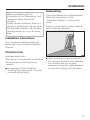
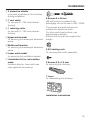
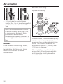
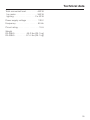
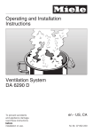
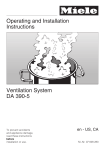
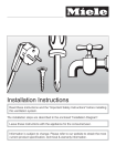
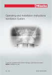
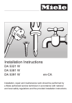
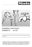
Installation Instructions
DA398-5
DA399-5
en-CA
Installation, repair and maintenance work should be performed by
a Miele authorized service technician in accordance with national
and local safety regulations and the provided installation instructions.
IMPORTANT SAFETY INSTRUCTIONS
READ AND SAVE THESE
INSTRUCTIONS
Keep these instructions in a safe
place and pass them on to any future
user.
Read these instructions carefully
before installing or using the
Ventilation System.
~ This appliance is intended for
residential use only. Use the appliance
only for its intended purpose.
~ This appliance complies with current
safety requirements. Improper use of
the appliance can lead to personal
injury and material damage.
,CAUTION
For General Ventilating Use
Only. Do Not Use To Exhaust
Hazardous Or Explosive
Materials And Vapors.
~
This appliance is designed to vent
cooking smoke and odors only.
~ This appliance is suitable for
installation above gas or electric
cooking surfaces.
~ This appliance is not designed for
maritime use or for use in mobile
installations such as recreational
vehicles or aircraft. However, under
certain conditions installation in these
applications may be possible. Please
contact your Miele dealer or the Miele
Technical Service Department with
specific requirements.
4
,WARNING
TO REDUCE THE RISK OF
FIRE, ELECTRIC SHOCK, OR
INJURY TO PERSONS,
OBSERVE THE FOLLOWING:
~ a) Use this appliance only in the
manner intended by the manufacturer.
If you have questions, contact Miele.
~ b) Before servicing or cleaning the
appliance, switch power off at the
service panel and lock the service
disconnecting means to prevent power
from being switched on accidentally. If
the service disconnecting means
cannot be locked, securely fasten a
prominent warning device, such as a
tag, to the service panel.
~ c) Be certain your appliance is
properly installed and grounded by a
qualified technician.
To guarantee the electrical safety of this
appliance, continuity must exist
between the appliance and an effective
grounding system. It is imperative that
this basic safety requirement be met. If
there is any doubt, have the electrical
system of the house checked by a
qualified electrician.
IMPORTANT SAFETY INSTRUCTIONS
~ d) Before connecting the appliance
to the power supply make sure that the
voltage and frequency listed on the
data plate correspond with the
household electrical supply.
This data must correspond to prevent
appliance damage. If in doubt consult a
qualified electrician.
~ e) Installation work and repairs
should only be performed by a qualified
technician in accordance with all
applicable codes and standards.
Repairs and other work by unqualified
persons could be dangerous.
~ f) Only open the housing as
described in the enclosed "Installation
diagram" and in the "Cleaning and care"
section of this manual. Under no
circumstances should any other parts
of the housing be opened. Tampering
with electrical connections or
components and mechanical parts is
highly dangerous to the user and can
cause operation faults.
~ g) Before discarding an old
appliance, disconnect it from the power
supply and remove the power cord to
prevent hazards.
Use
,WARNING
TO REDUCE THE RISK OF A
COOKTOP GREASE FIRE:
~ a) Never leave surface units
unattended at high settings. Boilovers
cause smoking and greasy spillovers
may ignite. Heat oils slowly on low or
medium settings.
~ b) Always turn the hood on when
cooking at a high heat.
~ c) Clean the ventilation hood
frequently. Grease should not be
allowed to accumulate on the fan or
filter.
~ d) Use the proper pan size. Always
use cookware appropriate for the size
of the cooking area.
~ e) Do not flambé or grill with an
open flame beneath the hood.
Flames could be drawn up into the
hood by the suction and the grease
filters may catch fire.
5
IMPORTANT SAFETY INSTRUCTIONS
,WARNING
TO REDUCE THE RISK OF
INJURY TO PERSONS IN THE
EVENT OF A COOKTOP
GREASE FIRE, OBSERVE THE
FOLLOWING*:
~ Do not allow children to play with or
~ a) SMOTHER FLAMES with a close
fitting lid, cookie sheet, or metal tray
then turn off the burner.
BE CAREFUL TO PREVENT BURNS.
If the flames do not go out immediately,
EVACUATE AND CALL THE FIRE
DEPARTMENT.
~ Never operate gas burners without
operate the appliance or its controls.
Supervise its use by the elderly or
infirm.
~ Always turn on the hood when using
the cooktop to prevent damage from
condensation.
PAN - You may be burned.
cookware. Turn the burner off when not
in use. Adjust the burner so that the
flames do not extend beneath the
cookware. Do not overheat the
cookware, e.g. when using a wok. The
hood can be damaged due to
excessive heat from the burners and
the cookware.
~ c) DO NOT USE WATER, including
~ Do not use the hood without the
~ b) NEVER PICK UP A FLAMING
wet dishcloths or towels - a violent
steam explosion will result.
~ d) Use a fire extinguisher ONLY if:
1) You have a class ABC
extinguisher, and you know how to
operate it.
2) The fire is small and contained in
the area where it started.
3) The fire department is being
called.
4)You can fight the fire with your
back to an exit.
*
6
Based on "Kitchen Firesafety Tips"
published by NAFTA
grease filters in place.
~ Do not use a steam cleaner to clean
the hood. Steam could penetrate
electrical components and cause a
short circuit.
IMPORTANT SAFETY INSTRUCTIONS
Installation
~ g) Do not install this hood over
cooktops that burn solid fuel.
,WARNING
TO REDUCE THE RISK OF
FIRE, ELECTRIC SHOCK, OR
INJURY TO PERSONS,
OBSERVE THE FOLLOWING:
~ a) Installation work and electrical
wiring must be done by qualified
person(s) in accordance with all
applicable codes and standards,
including fire-rated construction.
~ b) Sufficient air is needed for
combustion and exhausting of gases
through the flue (chimney of fuel
burning equipment to prevent back
drafting. Follow the heating equipment
manufacturer’s guideline and safety
standards such as those published by
the National Fire Protection Association
(NFPA) and the American Society for
Heating, Refrigeration and Air
Conditioning Engineers (ASHRAE), and
the local code authorities.
~ c) When cutting or drilling into the
wall or ceiling, do not damage electrical
wiring and other hidden utilities.
~ d) Ducted hoods must always be
vented to the outdoors.
~ e) Do not use this hood with any
solid-state speed control device.
~ h) Provided a larger distance is not
given by the manufacturer of the
cooktop, follow the minimum safety
distances between a cooktop and the
bottom of the hood given in the
"Appliance dimensions" section of this
manual.
If local building codes require a greater
safety distance, follow their
requirement.
If there is more than one appliance
beneath the hood and they have
different minimum safety distances
always select the greater distance.
~ i) Never connect an exhaust hood to
an active chimney, dryer vent, vent flue,
or room ventilating ductwork.
~ j) Seek professional advice before
connecting an exhaust hood vent to an
existing, inactive chimney or vent flue.
~ k) Any fittings, sealant, or materials
used to install the ductwork must be
made of approved non-flammable
materials.
,WARNING
TO REDUCE THE RISK OF
FIRE USE ONLY METAL
DUCTWORK.
~ f) Do not use an extension cord to
connect the appliance to electricity.
Extension cords do not guarantee the
required safety of the appliance,
(e.g. danger of overheating).
7
Appliance dimensions
Drawing is not to scale.
22
Appliance dimensions
a Ar extraction mode
b Recirculation mode
c Recirculation vent positioned at the
top (recirculation mode only)
d, e Installation area;
For recirculation mode only d.
Wall/ceiling area respectively for vent
hole and outlet installation.
For recirculation mode only the outlet
installation is required.
Connection for air extraction mode
6" (150 mm), with reducing collar
5" (125 mm).
23
Appliance dimensions
Distance between cooktop and hood (S)
Do not install this exhaust hood over cooktops burning solid fuel.
Provided a larger distance is not given by the manufacturer of the cooktop, follow
the minimum safety distances between a cooktop and the bottom of the hood:
Miele Cooktops
Non-Miele
Cooktops
Electric Cooktops
24" (610 mm)
Electric Barbeques and Fryers
26" (660 mm)
Multiburner Gas cooktops
< 43,000 BTU (12.6 KW)
and no burner > 15,000 BTU (4.5 KW)
26" (660 mm)
30" (760 mm)
Single burner (Wok) < 20,500 BTU (6 KW)
26" (660 mm)
30" (760 mm)
All other gas cooktops
30" (760 mm)
– If several gas surfaces are installed under the hood, the total output must be
considered when determining the minimum safety distance.
– Be sure to follow the minimum safety distances given by the gas cooktop
manufacturer to easily flammable materials e.g. upper cabinets.
– If local building codes require a greater safety distance, follow their requirement.
– If there is more than one appliance beneath the hood and they have different
minimum safety distances always select the greater distance.
See "Important Safety Instructions" for further information.
– To ensure free access to work under the ventilation hood, a distance of a
minimum of 26" (660 mm) above the electric cooktop is also recommended.
– Take the user's body height into consideration when selecting the installation
height. Adequate work space at the cooktop and optimal operation of the
ventilation system should be ensured.
– However, the greater the distance from the cooktop, the less effectively cooking
odors are drawn in.
– If the top of the hoods telescopic extension piece will be mounted flush to the
ceiling, regard the possible unit height when selecting the installation height.
24
Appliance dimensions
Drilling diagram
To prepare a backing plate, the
spacings for the 5 mm screws need to
be drilled as shown.
* The dimension between the ceiling
and the middle bracket may vary
depending on the position of the vent
cut-out and the power socket. It should
be installed as low as possible.
If the ventilation hood will be mounted
directly to the wall, follow the additional
instructions given in the included
"Installation diagram".
25
Plywood backing
The majority of the weight of the
installed ventilation system will be
supported by the lower retaining
plate. It must be firmly attached to
the stud framing behind the drywall.
If studs are not available in the
required locations, a plywood
backing (min. ½" (13 mm) thick)
spanning at least two studs must be
installed. Failure to adequately
support the weight as stated may
result in the ventilation system falling
off the wall, causing personal injury
and property damage.
(If plywood backing is not needed,
proceed to the included "Installation
diagram".)
To install a plywood backing
^ Determine and mark the location of
the retaining plate for the canopy as
outlined on the "Installation diagram".
^ Make a cutting line 3" (76 mm) above
and 3" (76 mm) below the outline of
the retaining plate.
26
^ Find the studs to the left and right of
the mounting location by tapping the
wall or using a stud finder.
^ Mark a vertical cutting line along the
center of each stud.
,CAUTION
When cutting or drilling into the wall
or ceiling, do not damage electrical
wiring and other hidden utilities.
^ Remove the drywall between the
cutting lines and replace it with
plywood of a matching thickness
(min. ½" (13 mm) thick). Tape the
joints and refinish the wall.
^ Proceed to the enclosed "Installation
diagram" to complete the installation.
Installation
Dismantling
Before installation read the
information in the "Dimensions" and
"Important Safety Instruction"
chapters.
Under certain conditions, there is a
danger of poisonous fumes by when
the ventilation system and a furnace
drawing interior air run at the same
time.
If the hood needs to be disassembled,
follow the instructions on the
"Installation diagram" in the reverse
order.
A lever is enclosed for easier removal
of the chimney extension.
Installation instructions
The individual installation steps are
described in the included Installation
diagram.
Protective film
(stainless steel units)
The casing is covered with a protective
film to prevent scratching during
transport.
^ Please peel off the film before
installing the casing parts. It can be
removed without tools.
^ After removing the two screws from
the chimney, slide the lever between
the chimney and the chimney
extension and gently apply pressure
to ease the chimney from its hooks.
27
Installation
Installation materials
28
Installation
a 3 protective shields
to prevent scratches to the chimney
during installation.
b 1 vent collar
for use with 6" (150 mm) exhaust
ducting.
6 Screws 5 x 40 mm
(S8 wall anchors included in the
packaging are not for use in USA / CDN)
c 1 reducing collar
for use with 5" (125 mm) exhaust
ducting.
The screws and wall anchors are
suitable for solid brick walls.
For other wall constructions, use
appropriate materials.
Ensure that the wall can support the
weight.
d Upper wall bracket
for securing the telescopic extension
piece
e Middle wall bracket
for securing the telescopic extension
piece
f Lower wall bracket
for securing the ventilation system
g Installation kit for recirculation
mode
contains diverter, hose and hose
clips (optional accessory).
2 M 6 locking nuts
for securing the motor assembly.
2 Screws 3.9 x 7.5 mm
for securing the chimney.
1 Lever
for dismantling the chimney.
Installation instructions
29
Electrical connection
,WARNING
TO REDUCE THE RISK OF
FIRE, ELECTRIC SHOCK, OR
INJURY TO PERSONS,
OBSERVE THE FOLLOWING:
All electrical work should be
performed by a qualified electrician
in strict accordance with national
regulations (for USA: ANSI-NFPA 70)
and local safety regulations.
Installation, repairs and other work
by unqualified persons could be
dangerous.
Ensure that power to the appliance
is off while installation or repair work
is performed.
^ Verify that the voltage, load and
circuit rating information found on the
data plate (located behind the
grease filters), match the household
electrical supply before installing the
hood.
^ Use only with ventilation hood
cord-connection kits that have been
investigated and found acceptable
for use with this model hood.
If there is any question concerning the
electrical connection of this appliance
to your power supply, please consult a
licensed electrician or contact Miele’s
Technical Service Department.
U
V
1-800-999-1360
1-800-565-6435
WARNING:
THIS APPLIANCE MUST BE
GROUNDED
30
Grounding Instructions
This appliance must be grounded. In
the event of an electrical short circuit,
grounding reduces the risk of electric
shock by providing a path of least
resistance. This appliance is equipped
with a cord having a grounding wire
with a grounding plug. The plug must
be plugged into an outlet that is
properly installed and grounded.
WARNING - Improper grounding can
result in a risk of electric shock.
If there is any doubt, have the electrical
system of the house checked by a
qualified electrician.
Do not use an extension cord. If the
power supply cord is too short, have a
qualified electrician install an outlet
near the appliance.
Important
The hood comes equipped with a 4 ft
(1.2 m) power cord with a NEMA 5-15
molded plug for connection to a 120 V,
60 Hz, 15 A power outlet.
Air extraction
,WARNING
Danger of toxic fumes.
Gas cooking appliances release
carbon monoxide that can be
harmful or fatal if inhaled.
To reduce the risk of fire and to
properly exhaust air, the exhaust
gases extracted by the hood
should be vented outside of the
building only.
Do not vent exhaust air into
spaces within walls or ceilings or
in attics, crawl spaces or garages.
To reduce the risk of fire, only use
metal ductwork.
Please read and follow the
"IMPORTANT SAFETY
INSTRUCTIONS" to reduce the risk of
personal injury. Follow all local building
codes when installing the hood.
Exhaust ducting and connections
Use smooth or flexible pipework made
from approved non-flammable
materials for exhaust ducting.
To achieve the most efficient air
extraction and quietest noise levels,
consider the following:
– The diameter of the ductwork should
not be less than 6" (150 mm).
– If flat ducting is used, the cross
section must not be smaller than the
cross section of the ventilation
exhaust.
– The ducting should be as short and
straight as possible.
– Use ductwork with a wide radius.
– The exhaust duct must not be bent
or compressed.
– Make sure all connections are
secure.
– Where the ductwork is horizontal, it
must slope away from the hood at
least 1/8" per foot (1 cm per meter) to
prevent condensation dripping into
the appliance.
– If the exhaust is ducted through an
outside wall, a Telescopic Wall Vent
can be used.
31
Air extraction
Condensate trap
optional accessory
– If the exhaust is ducted into an
inactive flue, the air must be expelled
parallel to the flow direction of the
flue.
Never connect an exhaust hood to
an active chimney, dryer vent, flue,
or room venting ductwork. Seek
professional advice before
connecting an exhaust hood vent to
an existing, inactive chimney or vent
flue.
Important
If the ductwork runs through rooms,
ceilings, garages, etc. where
temperature variations exist, it may
need to be insulated to reduce
condensation.
32
In some cases, a condensate trap may
also be required to collect and
evaporate any condensate which may
occur. This optional accessory is
available for ducts 5" (125 mm) and 6"
(150 mm) in diameter.
When installing a condensate trap,
ensure that it is positioned vertically
and if possible directly above the
exhaust outlet.
Technical data
Total connected load. . . . . . . . . . 450 W
fan motor . . . . . . . . . . . . . . . . . . 350 W
lighting . . . . . . . . . . . . . . . . . . 2 x 50 W
Power supply voltage . . . . . . . . . 120 V
Frequency . . . . . . . . . . . . . . . . . . 60 Hz
Circuit rating. . . . . . . . . . . . . . . . . . 15 A
Weight
DA 398-5 . . . . . . . . . . 55.2 lbs (25.1 kg)
DA 399-5 . . . . . . . . . 57.4 lbs (26.1 kg)
33
Alteration rights reserved / 1311
M.-Nr. 07 759 400 / 01
INFORMATION IS SUBJECT TO CHANGE. PLEASE REFER TO OUR WEBSITE TO OBTAIN THE MOST
CURRENT PRODUCT SPECIFICATIONS, TECHNICAL & WARRANTY INFORMATION.