1
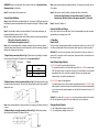
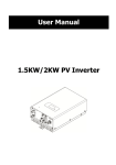
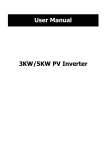
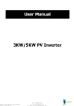
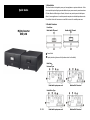
1. Introduction This robust inverter is designed to power your home appliances or precious electronics. It also Quick Guide can accept wide input voltage to generate stable and pure power source to power downstream AC loads. Based on different types of loads, this inverter can provide pure and stable power either to house appliances or to sensitive personal computers via selectable operation modes. It is a brilliant choice for home owners or small office users in the unstable power area. 2. Product Overview Front View: Mighty Inverter 850/1.5K Model with LED panel: Model with LCD panel: Power Switch Display indication (please see the Operation section for the details) Back View: Universal Type: Model with input power cord Model with AC terminal South Africa Type V. 2.1 Model with input power cord Model with AC terminal Personnel Precaution - Schuko Type Model with input power cord Input voltage range selector AC input Input breaker Model with AC terminal External battery connector Charge current selector (10A or 20A) Output receptacles CAUTION! Careful to reduce the risk or dropping a metal tool on the batteries. It could spark or short circuit the batteries and could cause an explosion. CAUTION! Remove personal metal items such as rings, bracelets, necklaces, and watches when working with batteries. Batteries can produce a short circuit current high enough to make metal melt, and could cause severe burns. CAUTION! Avoid touching eyes while working near batteries. CAUTION! Have plenty of fresh water and soap nearby in case battery acid contacts skin, clothing, or eyes. CAUTION! NEVER smoke or allow a spark or flame in vicinity of a battery. CAUTION! If a remote or automatic generator start system is used, disable the automatic starting circuit or disconnect the generator to prevent accident during servicing. 4. Specifications 3. Important Safety Warning (SAVE THESE INSTRUCTIONS) Before using the inverter, please read all instructions and cautionary markings on the unit, this manual and the batteries. General PrecautionConventions used: WARNING! Warnings identify conditions or practices that could result in personal injury; CAUTION! Caution identify conditions or practices that could result in damaged to the unit or other equipment connected. MODEL CAPACITY INPUT Voltage Voltage Range WARNING! It's very important for system safety and efficient operation to use appropriate OUTPUT Voltage Regulation (Batt. Mode) Transfer Time Waveform BATTERY Battery Voltage Floating Charge Voltage Maximum Charge Current Recommended Battery Capacity PHYSICAL Dimension (DxWxH) mm Net Weight (kgs) external battery cable. To reduce risk of injury, external battery cables should be UL certified and rated for 75° C or higher. And do not use copper cables less than 8AWG. 5. Installation CAUTION! The unit is designed for indoor use. Do not expose this unit to rain, snow or liquids of any type. CAUTION! To reduce risk of injury, only use qualified batteries from qualified distributors or manufacturers. Any unqualified batteries may cause damage and injury. Do NOT use old or overdue batteries. Please check the battery type and date code before installation to avoid damage and injury. WARNING! It's very important for system safety. AC input cable should be UL certified and rated for 105° C or higher. And do not use copper cables less than 18AWG. CAUTION! Do not disassemble the inverter. Contact with the qualified service center when service or repair is required. WARNING! Provide ventilation to outdoors from the battery compartment. The battery enclosure should be designed to prevent accumulation and concentration of hydrogen gas at the top of the compartment. CAUTION! Use insulated tools to reduce the chance of short-circuit when installing or working with the inverter, the batteries, or other equipments attached to this unit. CAUTION! For battery installation and maintenance, read the battery manufacturer's installation and maintenance instructions prior to operating. 850 850VA/600W 1.5K 1500VA/1050W 230VAC 180-260 VAC (For personal computer) 100-300 VAC (For home appliances) 230VAC ± 10 % 20 ms typical Simulated Sine Wave 12 VDC 13.7 VDC ± 2% 24 VDC 27.4 VDC ± 2% 10 A or 20 A 100 Ah – 200 Ah 289 x 290 x 127 9 12 NOTE: Before installation, please inspect the unit. Be sure that nothing inside the package is damaged. Assemble AC Input Cable (Only available for the unit with AC terminal) Step 1- Take away the cover of AC input connector. Step 2- Connect an input power cord to AC input terminal. Following AC input polarity (L, N, GND) guide printed near the terminal! (Refer to below chart) WARNING! Please use the appropriate AC input cable. Please refer to Important Safety Warnings Section for the details. Note: when connecting batteries in parallel connection, it’s necessary to use battery wires at #10 or above. Step 3- Screw tightly the AC input power cord. Step 3- Make sure to connect the polarity of battery side and the unit correctly. Positive pole (Red) of battery to the positive terminal (+)of the unit. Negative pole (Black) of battery to the negative terminal (-) of the unit. Connect External Battery Step 1- Install a DC Breaker in a positive battery line. The rating of the DC Breaker must be at least 60Amp to guarantee safe operation without interruption. Keep the DC breaker off. (see Fig. 1) Step 2- Connect battery cables to the external batteries. To have better performance, the recommended battery capacity is 100Ah – 200 Ah. Following battery polarity guide printed near the battery terminal to connect external batteries! RED cable to the positive terminal (+); BLACK cable to the negative terminal (-) Note: For the user operation safety, we strongly recommend that you should use tapes to isolate the battery terminals before you start to operate the unit. When connecting to external batteries, do not cause any short circuits. 1) Single battery connection (Refer to Fig. 1): When using a single battery, its voltage must be equal to the Nominal DC Voltage of the unit (see below Table 1). DC breaker Table 1 Model 850 1.5K Step 4- Take the DC breaker on. Connect to Utility and Charge Plug in the AC input cord to the wall outlet. The unit will automatically charge the connected external battery even though the unit is off. 6. Operation Power On/Off Once the inverter has been properly installed, press the power switch to turn on the unit. The unit will work automatically. When press the power switch again, the unit will be turned off. WARNING! The unit may have output power when connected to the utility, even though it is powered off. To completely cut off the output power, please switch off the unit and disconnect the unit from the utility. Input Voltage Range Selector Nominal Battery DC Voltage 12 VDC 24 VDC Fig. 1 2) Multiple batteries in series connection (Refer to Fig. 2): All batteries must be equal in voltage and amp hour capacity. The sum of their voltages must be equal to the nominal DC Voltage of the unit. Fig 2 Note: when connecting batteries in series connection, it’s necessary to use battery wires at #8 or above. 3) Multiple batteries in parallel connection (Refer to Fig. 3): Each battery's voltage must be equal to the Nominal DC Voltage of the unit. Fig 3 a). 180V-260V: setting for precious electronic devices If you select this mode, the unit's input utility range will be 180~260VAC as normal home UPS. If the utility is higher or lower than this range, the unit will transfer to inverter mode automatically. And you can connect the computer systems or other precision home equipment when you select this operation mode. b). 100V-300V: setting for home appliances If you select this mode, the unit's input utility range will be extended to 100~300VAC. If the utility is higher or lower than this range, the unit will transfer to inverter mode automatically. So, you can connect the home equipments, such as light bulb, fluorescent tube, fan, or TV on this mode. Caution!! If you select the home appliance mode and connect the computer to the output of the unit, the computer may reboot if the input voltage is too low to be accepted. Charging Current Selector a) b) High: setting battery charging current at 20A Low: setting battery charging current at 10A Model with LED Indicator & Audible Alarm There are three indicators (Green/Red/Yellow) in the front panel Status LED Indicator The unit is in Line mode. Green LED on. The unit is in Line mode and Green LED on and yellow LED charging battery. flashes every 3 seconds. Battery mode Yellow LED flashes every 10 seconds. Off-mode charging. Yellow LED flashes every 3 seconds. Overload warning Yellow LED flashes every 0.5 second Battery low warning Yellow LED flashes every 0.5 second Output is short circuited. Yellow LED and red LED are on. Overload fault Output voltage is too low or too high. Battery bad Red LED is on and Green LED flashes every 0.5 seconds. Battery is overcharging. Red LED and Green LED are on. Battery weak. Red LED flashes every 0.5 second. of the unit. Alarm Off 50%~75% 25%~50% Off Sounding every 0.5 second Sounding every second Continuously sounding. The unit will shut down after it’s in fault mode for 15 seconds. LCD Display Off and flashes Off Off-mode charging Battery weak at battery mode. 7. Trouble Shooting Use the table below to solve minor problems. Problem Possible Cause Solutions Utility power is normal AC input power cord is not Check AC input power connection. but the unit is in connected well. battery mode. Input breaker is activated. Reset the input breaker. When power fails, the The unit is overload. backup time is shorten. Battery voltage is too low. Alarm Battery mode The unit is overload. 0%~25% 12.5V (25V)> battery voltage ≥ 11.5V (23V) 11.5V (23V)> battery voltage ≥ 11.0V (22V) battery voltage < 11.0V (22V) Remove some non-critical loads. Charge the unit at least 8 hours. Battery capacity is not full Check the date code of the battery. If even after charge the unit for the batteries are too old, replace the at least 8 hours. batteries. Off Line mode with charging battery. Fault mode Battery capacity indicator: Display Battery Capacity battery voltage ≥ 12.5V (25V) Off Model with LCD Display & Audible Alarm Status Line mode Load level indicator: Display Load Level 75%~100% Off and flashes Fault code will be displayed. Output fault: F0 Overload: F1 Over-charging: F2 Battery bad: F3 High output voltage: F4 Low output voltage: F5 Battery weak: F6 The mark every second. The mark second. will flash will flash every Continuously sounding. The unit will shut down after it’s in fault mode for 15 seconds. Nothing display on the The unit is not turned on. Press power switch to turn on the front panel when the unit. utility power is Battery is not connected well. Check the external battery cable and normal. terminal. Make sure all the battery connections to the unit are all correct. Battery defect. Replace the batteries. Battery voltage is too low. The unit is in fault and The unit is overload. restart circularly. Charge the unit at least 8 hours. Verify that the load matches the capability specified in the specification. Output is short circuited. Check the loads and remove loads which cause short circuit. If there is any abnormal situations occur, which doesn't list above, please call the service people immediately for professional examine.