1
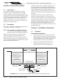
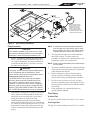
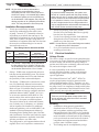
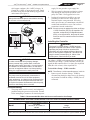
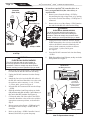
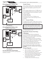
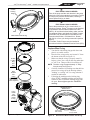
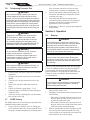
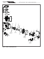
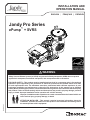
INSTALLATION AND
OPERATION MANUAL
ENGLISH | FRANÇAIS | ESPAÑOL
Jandy Pro Series
ePump™ + SVRS
WARNING
Safety Vacuum Release System (or SVRS) may prevent full body entrapment; SVRS does not protect
against hair entrapment, mechanical entrapment, limb entrapment and/or evisceration.
H0414300 Rev C
FOR YOUR SAFETY - This product must be installed and serviced by a contractor who is licensed and
qualified in pool equipment by the jurisdiction in which the product will be installed where such state
or local requirements exist. The maintainer must be a professional with sufficient experience in pool
equipment installation and maintenance so that all of the instructions in this manual can be followed
exactly. Before installing this product, read and follow all warning notices and instructions that accompany
this product. Failure to follow warning notices and instructions may result in property damage, personal
injury, or death. Improper installation and/or operation will void the warranty.
Improper installation and/or operation can create unwanted electrical hazard which can
cause serious injury, property damage, or death.
ATTENTION INSTALLER - This manual contains important information about the
installation, operation and safe use of this product. This information should be given to
the owner/operator of this equipment.
Page 2
ENGLISH
Jandy® Pro Series ePump™ + SVRS | Installation and Operation Manual
Table of Contents
Section 1. Important Safety Instructions.............. 3
1.1
1.2
Safety Instructions................................. 3
Pool Pump Suction Entrapment
Prevention Guidelines........................... 6
1.3 Virginia Graeme Baker Pool and Spa
Safety Act.............................................. 7
Section 2. General Description.............................. 8
2.1Introduction............................................ 8
2.2Description............................................. 8
Section 3. Installation Information........................ 8
3.1Plumbing................................................ 8
3.2 Electrical Installation.............................. 10
3.3 ePump Dip Switch Settings................... 13
3.4 Auxiliary Load Operation....................... 13
3.5 Pressure Testing.................................... 14
3.6 Conducting Pressure Test..................... 16
3.7 SVRS Testing........................................ 16
Section 4. Operation............................................... 16
4.1Start-up.................................................. 16
4.2 SVRS Tripping....................................... 17
Section 5. Service and Maintenance..................... 17
5.1 Routine Maintenance............................. 17
5.2 Winterizing the Pump............................ 17
Section 6. Troubleshooting and Repair................ 18
6.1 Service Technician Maintenance........... 18
6.2Troubleshooting..................................... 19
Section 7. Product Specifications and
Technical Data....................................... 21
7.1
7.2
7.3
Replacement Parts List and Exploded
View....................................................... 21
Performance Curves.............................. 23
Physical and Operational
Specifications........................................ 23
EQUIPMENT INFORMATION RECORD
DATE OF INSTALLATION
INSTALLER INFORMATION
INITIAL PRESSURE GAUGE READING (WITH CLEAN FILTER)
PUMP MODEL
NOTES:
HORSEPOWER
Jandy® Pro Series ePump™ + SVRS | Installation and Operation Manual
ENGLISH
Page 3
Section 1. IMPORTANT SAFETY INSTRUCTIONS
READ AND FOLLOW ALL INSTRUCTIONS
1.1
Safety Instructions
All electrical work must be performed by a licensed electrician and conform to all national, state, and local codes. When
installing and using this electrical equipment, basic safety precautions should always be followed, including the following:
WARNING
RISK OF SUCTION ENTRAPMENT HAZARD, WHICH, IF NOT AVOIDED, CAN
RESULT IN SERIOUS INJURY OR DEATH. Do not block pump suction, as this can
cause severe injury or death. Do not use this pump for wading pools, shallow pools,
or spas containing bottom drains, unless the pump is connected to at least two (2)
functioning suction outlets. Drain covers must be certified to the latest published
edition of ANSI®/ASME® A112.19.8 or its successor standard, ANSI/APSP-16. It is
absolutely critical that the suction plumbing be installed in accordance with the latest
national and local codes for swimming pools.
WARNING
A hydrostatic valve installed in the suction piping of the pool cirulation system can increase the time that
high vacuum is present at the suction outlet, even if an SVRS device is installed in the system.
IN ORDER TO PREVENT RISK OF SERIOUS INJURY OR DEATH. Do NOT use suction check valves
and/or hydrostatic valves with this pump.
• The SVRS feature of this pump may not operate effectively when the pump is installed more than 3
feet above or below the water level of the pool. Therefore, to reduce the risk of suction entrapment,
which can result in serious injury or death, DO NOT INSTALL THE PUMP MORE THAN 3 FEET
ABOVE OR 3 FEET BELOW the water level of the pool/spa.
WARNING
This pump has a motor equipped with a Safety Vacuum Release System (SVRS) that complies with
ANSI/ASME A112.19.17. SVRS helps prevent full-body entrapment on drains due to suction. In some
pools, if a person's body covers the suction outlet (drain), they can be trapped by suction. If this occurs,
a SVRS can act to release the suction to help prevent drowning.
SVRS does NOT protect against other suction-outlet (drain) hazards such as:
• Hair entanglement - hair tangled/caught in suction-outlet
• Mechanical Entrapment -- jewelery, swimsuits, fingers, etc... caught in suction outlet.
• Limb Entrapment - arms or legs trapped in uncovered or broken drains.
• Evisceration/Disembowelment - suction force at suction-outlet can pull lower intestine out of rectum,
causing irreversible damage.
WARNING
Properly designed and installed suction-outlet covers help protect against all of the above hazards. This
SVRS pump is NOT a substitute for a properly designed and installed suction-outlet cover. All suction
outlets must be equipped with their designated covers and the complete Suction Outlet Fitting Assembly
(SOFA) must be in good condition and must be certified and marked to indicate compliance with ANSI/
ASME A112.19.8, or its successor standard ANSI/APSP-16, the standard for Suction Fittings for use in
Swimming Pools, Wading Pools, Spas, and Hot Tubs.
WARNING
Prior to bather use, the ePump + SVRS should be tested for proper functionality in the following manner.
A ball, butterfly, or sliding gate valve shall be installed within 2 ft. (0.6m) upstream from the ePump +
SVRS (between the ePump + SVRS and the protected suction outlet), or a test mat shall be used to
cover the suction outlet to simulate an entrapment event. There shall be three simulated entrapment
tests conducted to verify proper adjustment and operation of the device.
Page 4
ENGLISH
Jandy® Pro Series ePump™ w/SVRS | Installation and Operation Manual
WARNING
The SVRS feature on this pump is inactive up to ten (10) minutes after power up. During this period,
the pump does not monitor blocked suction or discharge system condition. Keep bathers out of the pool
when SVRS is not active, such as during the first ten (10) minutes after power up.
WARNING
To reduce the risk of injury, do not permit children and/or adults not familiar and experienced with the
operation of swimming pool pumps to use this product unless they are closely supervised at all times.
WARNING
RISK OF ELECTRIC SHOCK, FIRE, PERSONAL INJURY, OR DEATH. Always disconnect power to
the pump at the circuit breaker and remove the RS-485 communication cable from the pump before
servicing the pump.
WARNING
To reduce the risk of property damage or injury, do not attempt to change the backwash (multiport, slide,
or full flow) valve position with the pump running.
WARNING
Zodiac Pumps are powered by a high-voltage electric motor and must be installed by a licensed or
certified electrician or a qualified swimming pool service technician.
®
WARNING
Due to the potential risk of fire, electric shock, or injuries to persons, Zodiac Pumps must be installed
in accordance with the National Electrical Code® (NEC®), all local electrical and safety codes, and the
Occupational Safety and Health Act (OSHA). Copies of the NEC may be ordered from the National Fire
Protection Association, 470 Atlantic Ave., Boston, MA 02210, or from your local government inspection agency.
WARNING
RISK OF ELECTRIC SHOCK, FIRE, PERSONAL INJURY, OR DEATH. Never open the drive motor
enclosure. Connect only to a branch circuit that is protected by a ground-fault circuit-interrupter (GFCI).
Contact a qualified electrician if you cannot verify that the circuit is protected by a GFCI. Make sure a
GFCI is be provided by the installer and is tested on a routine basis. To test the GFCI, push the test
button. The GFCI should interrupt power. Push the reset button. Power should be restored. If the GFCI
fails to operate in this manner, the GFCI is defective. If the GFCI interrupts power to the pump without
the test button being pushed, a ground current is flowing, indicating the possibility of electrical shock.
Do not use the device. Disconnect the device and have the problem corrected by a qualified service
representative before using.
WARNING
When installed in a location other than single-family dwellings, the National Electrical Code (NEC,
NFPA-70) requires the installation of a clearly labeled Emergency Shutoff Switch, which shall be readily
accessible to the occupants of the pool/spa. Such a switch shall be within sight but at least 5 feet
(1.52m) from the pool or spa.
WARNING
Incorrectly installed equipment may fail, causing severe injury or property damage.
WARNING
•• Do not connect system to an unregulated city water system or other external source of pressurized
water producing pressures greater than 35 PSI.
•• Trapped air in the system can cause the filter lid to be blown off, which can result in death, serious
personal injury, or property damage. Be sure all air is out of the system before operating.
Jandy® Pro Series ePump™ w/SVRS | Installation and Operation Manual
ENGLISH
Page 5
WARNING
The Jandy Pro Series ePump + SVRS is capable of generating system pressures up to 50 psi. Installers
must ensure that all system components are rated to withstand at least 50 psi. Over pressurizing the
system can result in catastrophic component failure or property damage.
WARNING
To minimize risk of severe injury or death, the filter and/or pump should not be subjected to the piping
system pressurization test.
Local codes may require the pool piping system to be subjected to a pressure test. These requirements
are generally not intended to apply to the pool equipment, such as filters or pumps.
Zodiac® pool equipment is pressure tested at the factory.
If, however, the WARNING cannot be followed and pressure testing of the piping system must include
the filter and/or pump, BE SURE TO COMPLY WITH THE FOLLOWING SAFETY INSTRUCTIONS:
•• Check all clamps, bolts, lids, lock rings, and system accessories to ensure they are properly installed
and secured before testing.
•• RELEASE ALL AIR in the system before testing.
•• Water pressure for test must NOT EXCEED 35 PSI.
•• Water temperature for test must NOT EXCEED 100°F (38°C).
•• Limit test to 24 hours. After test, visually check system to be sure it is ready for operation.
Notice: These parameters apply to Zodiac equipment only. For non-Zodiac equipment, consult the
equipment manufacturer.
WARNING
Chemical spills and fumes can weaken pool/spa equipment. Corrosion can cause filters and other
equipment to fail, resulting in severe injury or property damage. Do not store pool chemicals near your
equipment.
CAUTION
Do not start pump dry! Running the pump dry for any length of time will cause severe damage and will
void the warranty.
••
••
••
••
••
CAUTION
This pump is for use with permanently installed pools and may also be used with hot tubs and spas,
if so marked. Do not use with storable pools. A permanently installed pool is constructed in or on
the ground or in a building, such that it cannot be readily disassembled for storage. A storable pool
is constructed so that it may be readily disassembled for storage and reassembled to its original
integrity.
Do not install beneath the skirt of a hot tub. The pump requires adequate ventilation to maintain air
temperature at less than the maximum ambient temperature rating listed on the motor rating plate.
For Canadian installation, this pump carries a Type 3R enclosure rating and therefore is not intended
for installation in areas subjected to windblown dust.
Install the pump such that any disconnecting means and/or junction boxes for power connection are
within site of the pump and at least five (5) feet from the inside wall of the pool and spa. Canadian
installations require a minimum of three (3) meters from the pool water.
Refer to the "Bonding" instructions in section 3.2 of this manual and consult local & national
codes for using a No. 8 AWG or larger conductor to properly bond the pump motor to other metal
components and electrical equipment in the vicinity of the pool/spa.
Page 6
ENGLISH
Jandy® Pro Series ePump™ w/SVRS | Installation and Operation Manual
WARNING
The Jandy Pro Series ePump + SVRS has been designed to operate with Zodiac® control systems.
Operating the pump with other manufacturers' controllers may cause software failure of the pump, drive
or other system components. This failure can result in severe personal injury (i.e., failure of the SVRS
system, electrical shock) or death.
DANGER
Entrapment Avoidance Notice: Drain covers must be certified to the latest published edition
of ANSI®/ASME® A112.19.8 or its successor standard, ANSI/APSP-16. These covers should be
inspected regularly and replaced if cracked, broken or older than the design lifetime indicated on
them by the manufacturer. The maximum possible flow rate of this pump should be less than or equal
to the maximum approved flow rate indicated on the suction outlet cover by the manufacturer. THE
USE OF UNAPPROVED COVERS OR ALLOWING USE OF THE POOL OR SPA WHEN COVERS
ARE MISSING, CRACKED OR BROKEN CAN RESULT IN BODY OR LIMB ENTRAPMENT, HAIR
ENTANGLEMENT, EVISCERATION AND DEATH.
1.2
Pool Pump Suction Entrapment Prevention Guidelines
WARNING
SUCTION HAZARD. Can cause serious injury or death. Do not use this pump for wading
pools, shallow pools, or spas containing bottom drains, unless pump is connected to at
least two (2) functioning suction outlets.
WARNING
Pump suction is hazardous and can trap and drown or disembowel bathers. Do not use or operate
swimming pools, spas, or hot tubs if a suction outlet cover is missing, broken, or loose. The
following guidelines provide information for pump installation that minimizes risk of injury to users of
pools, spas, and hot tubs:
Entrapment Protection - The pump suction system must provide protection against the hazards of
suction entrapment.
Suction Outlet Covers - All suction outlets must have correctly installed, screw-fastened covers in place.
All suction outlet (drain) covers must be properly maintained. They must be replaced if cracked, broken,
or missing. Drain covers must be listed/certified to the latest published edition of ANSI/ASME A112.19.8
or its successor standard, ANSI/APSP-16. The pool must be shut down and bathers must be restricted
from entering the pool until any cracked, broken, or missing drain covers are replaced.
Number of Suction Outlets Per Pump - Provide at least two (2) hydraulically-balanced suction outlets,
with covers, as suction outlets for each circulating pump suction line. The centers of the suction outlets
(suction outlets) on any one (1) suction line must be at least three (3) feet apart, center to center. See
Figure 1.
The system must be built to include at least two (2) suction outlets (drains) connected to the pump
whenever the pump is running. However, if two (2) suction outlets run into a single suction line, the single
suction line may be equipped with a valve that will shut off both suction outlets from the pump. The
system shall be constructed such that it shall not allow for separate or independent shutoff or isolation of
each drain. See Figure 1.
Additional pumps can be connected to a single suction line as long as the requirements above are met.
SAVE THESE INSTRUCTIONS
Jandy® Pro Series ePump™ w/SVRS | Installation and Operation Manual
ENGLISH
Page 7
WARNING
Water Velocity - The maximum water velocity through the suction outlet assembly and its cover for any
suction outlet must not exceed the suction outlet assembly and its cover's maximum design flow rate.
The suction outlet (drain) assembly and its cover must comply with the latest version of ANSI®/ASME®
A112.19.8, the standard for Suction Fittings For Use in Swimming Pools, Wading Pools, Spas,and Hot
Tubs, or its successor standard, ANSI/ASME APSP-16.
Testing and Certification - Suction outlet covers must have been tested by a nationally recognized
testing laboratory and found to comply with the latest published edition of ANSI/ASME A112.19.8 or
its successor standard, ANSI/APSP-16, the standard for Suction Fittings For Use in Swimming pools,
Wading Pools, Spas, and Hot Tubs.
Fittings - Fittings restrict flow; for best efficiency use fewest possible fittings (but at least two (2) suction
outlets).
Avoid fittings that could cause an air trap.
Pool cleaner suction fittings must conform to applicable International Association of Plumbing and
Mechanical Officials (IAPMO) standards.
1.3 VIRGINIA GRAEME BAKER POOL AND SPA SAFETY ACT
The Virginia Graeme Baker Pool and Spa Safety Act raises certain new requirements on owners and
operators of public swimming pools and spas.
Public pools or spas constructed on or after December 20, 2008, shall utilize:
(A) No submerged suction outlets, a gravity drainage system with ASME/ANSI cover(s), one or
more unblockable outlets; or
(B) A multiple suction outlet system without isolation capability with suction outlet covers that
meet ASME/ANSI A112.19.8 Suction Fittings for Use in Swimming Pools, Wading Pools,
Spas, and Hot Tubs and either:
(i) A safety vacuum release system (SVRS) meeting ASME/ANSI A112.19.17 Manufactured
Safety Vacuum Release Systems (SVRS) for Residential and Commercial Swimming
Pool, Spa, Hot Tub, and Wading Pool Suction Systems and/or ASTM F2387 Standard
Specification for Manufactured Safety Vacuum Release Systems (SVRS) for Swimming
Pools, Spas and Hot Tubs or
(ii) A properly designed and tested suction-limiting vent system or
(iii) An automatic pump shut-off system.
Public pools and spas construction prior to December 20, 2008, with a single submerged suction outlet
shall use a suction outlet cover that meets ASME/ANSI A112.19.8 and either:
(A) A multiple suction outlet system without isolation capability, or
(B) A safety vacuum release system (SVRS) meeting ASME/ANSI A112.19.17 and/or ASTM
F2387, or
(C) A properly designed and tested suction-limiting vent system, or
(D) An automatic pump shut-off system, or
(E) Disabled submerged outlets, or
(F) Suction outlets shall be reconfigured into return inlets.
For more information about the Act, contact the Consumer Product Safety Commission at
301.504.7908 or visit www.cpsc.gov.
Page 8
ENGLISH
Jandy® Pro Series ePump™ w/SVRS | Installation and Operation Manual
Section 2.General Description
2.1Introduction
This manual contains information for the proper
installation, operation, and maintenance of Jandy
Pro Series ePump + SVRS (Safety Vacuum Release
System) Series variable-speed pump. Procedures in this
manual must be followed exactly. To obtain additional
copies of this manual, contact Zodiac® Technical
Support at 800.822.7933 or visit our website at www.
zodiacpoolsystems.com. For address information, see
the back cover of this manual.
2.2Description
The ePump + SVRS is a variable-speed pump that can
be run from 1050 RPM to 3450 RPM.
NOTE Some controllers may display speeds lower
than 1050 RPM even though the pump only
operates between 1050 RPM and 3450 RPM.
When connected to the ePump + SVRS controller
(JEP-R), up to eight (8) speed settings may be
programmed and recalled. This allows you to select
the most appropriate speed for your application. Even
more versatile programming is possible when you use a
Zodiac AquaLink® RS controller.
Jandy Pro Series ePump + SVRS is designed to meet
the needs of today’s more hydraulically demanding
pool equipment. The pump housing, backplate, diffuser,
impeller, and hair and lint pot (filter basket) are all
made from high quality thermoplastic materials. These
materials were chosen for their strength and corrosion
resistance.
The pump is driven by an electric motor directly
attached to the pump impeller. As the electric motor
turns, it causes the impeller to turn, which forces water
to flow through the pump. The water flows through the
pump inlet and then into the filter basket. The basket
assembly pre-strains/traps large particles. The water
then enters the center of the pump housing, flows
through the impeller into the diffuser, and flows out the
pump discharge port.
Section 3.Installation Information
3.1Plumbing
Preparation Information
1.
Upon receipt of the pump, check the carton for
damage. Open the carton and check the pump for
concealed damage, such as cracks, dents or a bent
base. If damage is found, contact the shipper or
distributor where the pump was purchased.
2.
Inspect the contents of the carton and verify
that all parts are included. See Section 7.1,
Replacement Parts List and Exploded View.
At Least
3 Feet
Listed/Certified to latest
published edition of
ANSI /ASME A112.19.8
or its successor standard, ANSI/APSP-16
Anti-entrapment
Cover/Grate or Suction
Fitting, Screw-fastened
to Main Drain Sump
®
®
No Valves between
Tee and Main Drains
Suction Outlet
(Main Drain)
Listed/Certified to latest
published edition of
ANSI/ASME A112.19.8
or its successor standard, ANSI/APSP-16
Anti-entrapment
Cover/Grate or Suction
Fitting, Screw-fastened
to Main Drain Sump
Suction Outlet
(Main Drain)
Valves OK between
Pump and Tee
Pump
WARNING: Suction check valves and hydrostatic valves should not be used with this pump.
Figure 1. Number of Suction Outlets Per Pump
ENGLISH
Jandy® Pro Series ePump™ + SVRS | Installation and Operation Manual
Page 9
AQUAPURE
MANUAL BY-PASS DETAIL
MANUAL BY-PASS IS USED
WHEN FILTRATION RATE
EXCEEDS 125 GPM FOR
ZODIAC HEATERS. REFER
TO THE MANUFACTURERS
RECOMMENDATIONS IF USING
A DIFFERENT BRAND HEATER.
Figure 2. Typical Piping Installation
Pump Location
CAUTION
For Canadian installation, this pump carries a Type
3R enclosure rating and therefore is not intended for
installation in areas subjected to windblown dust.
1.Zodiac® recommends installing the pump within
one (1) foot above water level. Refer to Figure 2
for a typical installation. The pump should not be
elevated more than three (3) feet above or below
the water level of the pool.
WARNING
This Safety Vacuum Release System (SVRS) device
is NOT compatible with the installation of check
valves. Suction check valves and hydrostatic valves
should not be used with this pump.
The SVRS feature of this pump may not operate
effectively when the pump is installed more than
3 feet above or below the water level of the pool.
Therefore, to reduce the risk of suction entrapment,
which can result in serious injury or death, DO NOT
INSTALL THE PUMP MORE THAN 3 FEET ABOVE
OR 3 FEET BELOW the water level of the pool/spa.
2.
3.
If the pump is located below water level, isolation
valves must be installed on both the suction and
return lines to prevent back flow of pool water
during any routine or required servicing.
Install the pump such that any disconnecting
means and/or junction boxes for power connection
are within site of the pump and at least five (5) feet
horizontally from the edge of the pool and/or spa.
Choose a location that will minimize turns in the
piping.
NOTE In Canada the minimum distance maintained
from the edge of the pool and/or spa as noted
above must be 3m (10 feet), as required by the
Canadian Electrical Code (CEC, CSA C22.1).
4.
The pump must be placed on a solid foundation
that will not vibrate. To further reduce the
possibility of vibration noise, bolt the pump to the
foundation, or place it on a rubber mat.
NOTE Zodiac recommends bolting the pump directly to
the foundation.
5. The pump foundation must have adequate drainage
to prevent the motor from getting wet. Protect the
pump from the rain and sun.
6. Proper ventilation is required for the pump to
operate normally. All motors generate heat that
must be removed by providing proper ventilation.
7. Provide access for future services by leaving a
clear area around the pump. Allow plenty of space
above the pump to remove the lid and filter basket
for cleaning.
8. If the equipment is in a potentially dark area,
provide adequate lighting.
Pipe Sizing
Suction Pipe
The pipe size on the suction side will be 2.5 to 3 inches.
Discharge Pipe
The pipe size on the discharge side will be 2 to 3 inches.
Page 10
ENGLISH
Jandy® Pro Series ePump™ + SVRS | Installation and Operation Manual
NOTE All pipe sizes are able to withstand the
pressures the pump will deliver, but not
necessarily the flow. If the suction pipe is too
small for the pump, or is elevated above water,
the maximum gallons per minute (GPM) may
not be delivered. If this happens, the pump will
develop a pocket of air (cavitation) that makes
noise. This may shorten the life of the pump.
Installation Recommendations
1.
To help prevent difficulty in priming, install the
suction pipe without high points (above inlet
of pump - inverted “U”s, commonly referred to
in plumbing as an airlock) that can trap air. For
installations of equipment up to 100 feet from the
water, refer to Table 1, the pipe sizing chart. For
installations of equipment more than 100 feet from
the water, the recommended pipe size must be
increased to the next size.
Table 1.
Pipe Sizing Chart for Schedule 40 PVC
Pipe
Size
Maximum Flow
Suction
(6 feet per second)
Maximum Flow
Discharge
(8 feet per second)
2"
62 GPM (235 LPM)
85 GPM (322 LPM)
2½"
88 GPM (333 LPM)
120 GPM (454 LPM)
NOTE The ePump + SVRS shall only be operated in
the flow range of 27 to 155gpm. The pipe size
on the discharge side will be 2 to 3 inches and
on the suction side it will be 2.5 to 3 inches.
2.
3.
4.
ePump + SVRS comes equipped with unions on
both the suction and discharge ports. This feature
simplifies installation and service and eliminates
the possibility of leaks at threaded adapters.
The ePump + SVRS must be connected to at least
two (2) hydraulically-balanced suction outlets
(suction outlets) for each pool pump suction line.
Refer to Figure 2. Each drain must be provided
with covers that are listed or certified to the latest
published edition of ANSI®/ASME® A112.19.8
or its successor standard, ANSI/APSP-16. The
suction outlets of the suction outlets must be at
least three (3) feet apart or at different planes.
The suction outlets can be a drain and skimmer,
two (2) drains, two (2) skimmers, or a skimmer
with an equalizer line installed. For additional
details and guidelines, refer to ANSI/APSP 7, the
standard for Suction Entrapment Avoidance in
Swimming Pools, Wading Pools, Spas, Hot Tubs,
and Catch Basins. Check the local codes for proper
installation requirements. Applicable local codes
will take precedence over other codes.
The piping must be well supported and not forced
together where it will experience constant stress.
WARNING
To prevent full-body entrapment, the system must
be built so it cannot operate with the pump drawing
water from only one (1) suction outlet. At least two (2)
suction outlets must be connected to the pump when
it is in operation. However, if two (2) suction outlets
run into a single suction line, the single suction line
may be equipped with a valve that will simultaneously
shut off both suction outlets from the pump.
5.
6.
Always use properly sized valves. Zodiac®
Diverter Valves and Zodiac Ball Valves typically
have the best flow capabilities.
Use the fewest fittings possible. Each additional
fitting has the effect of moving the equipment
farther away from the water.
NOTE If more than ten (10) suction fittings are needed,
the pipe size must be increased.
7.
Every new installation must be pressure tested
according to local codes.
3.2 Electrical Installation
Voltage Checks
The correct voltage, as specified on the pump data plate,
is necessary for proper performance and long motor life.
Incorrect voltage will decrease the pump’s ability to
perform and could cause overheating, reduce the motor
life, and result in higher electric bills.
It is the responsibility of the electrical installer to
provide data plate operating voltage to the pump by
ensuring proper circuit sizes and wire sizes for this
specific application.
The National Electrical Code® (NEC®, NFPA-70)
requires all pool pump circuits be protected with a
Ground Fault Interrupter (GFCI). Therefore, it is also
the responsibility of the electrical installer to ensure that
the pump circuit is in compliance with this and all other
applicable requirements of the National Electrical Code
(NEC) and any other aplicable installation codes.
CAUTION
Failure to provide data plate voltage (within 10%)
during operation will cause the motor to overheat
and void the warranty.
Bonding
1.
2.
In addition to being properly grounded as
described below in Electrical Wiring section,
and in accordance with the requirements of the
National Electrical Code (NEC), or in Canada the
Canadian Electrical Code (CEC), the pump motor
must be bonded to all metal parts of the swimming
pool, spa or hot tub structure and to all electrical
components and equipment associated with the
pool/spa water circulation system.
The bonding must be accomplished by using a
ENGLISH
Jandy® Pro Series ePump™ + SVRS | Installation and Operation Manual
solid copper conductro, No. 8 AWG or larger. In
Canada No. 6 AWG or larger must be used. Bond
the motor using the external bonding lug provided
on the motor (See figure 3).
WARNING
Always disconnect the power source before working
on a motor or its connected load.
supply. Do not ground to a gas supply line.
2.
3.
Bonding Lug
Wire size must be adequate to minimize voltage
drop during the start-up and operation of the
pump. See Table 2 for suggested wire sizes.
Insulate all connections carefully to prevent
grounding or short-circuits. Sharp edges on
terminals require extra protection. For safety,
and to prevent entry of contaminants, reinstall all
conduit and terminal box covers. Do not force
connections into the conduit box.
NOTE Since the pump is operated by either an ePump
+ SVRS controller (JEP-R), an AquaLink® RS
controller, an AquaLink Pool Digital Assistant
(PDA), or an AquaLink Z4, the pump will not be
turned on until it is turned on with one of these
controllers.
Breaker Panel
GROUND
NEUTRAL
L1
L2
Installing the Controller
Terminal Block
Circuit
Breaker
Variable-Speed
Pump (230 VAC)
Figure 3.
Page 11
Bonding the Motor
WARNING
In order to avoid the risk of property damage,
severe personal injury, and/or death, make sure
that the control switch, time clock, or control system
is installed in an accessible location, so that in the
event of an equipment failure or a loose plumbing
fitting, the equipment can be easily turned off.
CAUTION
The pump must be permanently connected to a
dedicated electrical circuit. No other equipment,
lights, appliances, or outlets may be connected to the
pump circuit, with the exception of devices that may
be required to operate simultaneously with the pump,
such as a chlorinating device or heater.
WARNING
The Jandy Pro Series ePump + SVRS has been
designed to operate with Zodiac® control systems.
Operating the pump with other manufacturers'
controllers may cause software failure of the pump,
drive or other system components. This failure can
result in severe personal injury (ie. failure of the
SVRS system, electrical shock) or death.
The ePump + SVRS can be operated by one of four (4)
controllers: the ePump + SVRS controller (JEP-R), the
AquaLink RS controller (Rev O or later), the AquaLink
PDA (Rev 4.0 or later), or the AquaLink Z4.
To install the ePump + SVRS controller:
NOTE The ePump + SVRS controller part no. is JEP-R.
1.
Remove power from the ePump + SVRS by
disconnecting the high voltage lines or by opening
any breaker to which the ePump + SVRS power is
connected.
Electrical Wiring
1.
The pump motor must be securely and adequately
grounded using the green screw provided. Ground
before attempting to connect to an electrical power
Table 2. Recommended Wire Size and Overcurrent Protection for ePumps
MINIMUM WIRE SIZE AND OVERCURRENT PROTECTION FOR ePUMP SERIES PUMPS*
Distance from Sub-panel
Model
JEP2.0SVRS
0 - 150 Feet (0-45 meters)
Inverse - Time Circuit Breaker or Branch
Fuse AMPS
Class:CC, G, H, J, K, RK, or T
230 VAC
20A Max
Voltage
208-230 VAC
#12 solid copper minimum
*Assumes three (3) copper conductors in a buried conduit and 3% maximum voltage loss in branch circuit. All National Electrical Code®
(NEC®) and local codes must be followed. Table shows minimum wire size and branch fuse recommendations for typical installation per NEC.
Page 12
ENGLISH
Jandy® Pro Series ePump™ + SVRS | Installation and Operation Manual
RS485
4 3 2 1
INPUT 3
INPUT 4
COMMON
INPUT 2
INPUT 1
BLACK
RED
YELLOW
GREEN
RED
BLACK
YELLOW
GREEN
Controller
(Rear View)
5 4 3 2 1
REMOTE CONTROL
RS485
Cable
Grounding Lug
To install an AquaLink® RS controller (Rev O or
later), an AquaLink PDA (Rev 4.0 or later), or
AquaLink Z4:
1. Remove power from the ePump + SVRS by
disconnecting the high voltage lines or by opening
any breaker to which the ePump + SVRS power is
connected.
2.
Remove the cover of the ePump + SVRS junction
box and feed the RS-485 cable into the fitting.
WARNING
ELECTRICAL SHOCK HAZARD
Turn off all switches and the main breaker in
the ePump electrical circuit before starting the
procedure. Failure to comply may cause a shock
hazard, resulting in severe personal injury or death.
4.
Insert the RS-485 connector back into the ePump
+ SVRS.
ePump + SVRS
5. Slide dip switches 1 and 2 down, so they are in the
OFF position. See Figure 5.
Turn off all switches and the main breaker in
the ePump electrical circuit before starting the
procedure. Failure to comply may cause a shock
hazard, resulting in severe personal injury or death.
10 9 8 7 6 5 4 3 2 1
RS6 & RS8 ONLY
RS8 ONLY
POOL MODE
6
7
5
X
X
X
AU
SPA MODE
AU
2
4
AU
X
AU
1
X
X
PU
X
ER
LT
FI
3
P
M
AUTO
SERVICE
6 5 4 3 2 1
4 3 2 1
RESET
AU
4 3 2 1
S1
AU
2.
HEATER
SOLAR
SPA DRAIN
SPA FILL
TIME OUT
RED
BLACK
YELLOW
GREEN
GREEN
S2
4 3 2 1
Connect to
AquaLink RS
RS-485 Connector
(or Multiplexer
Interface Board)
RS485
Cable
Remove the cover of the ePump + SVRS junction
box and feed the RS-485 cable into the fitting.
3. Unplug the RS-485 connector from the ePump +
SVRS.
4. Attach the four (4) wires in the RS-485 cable to
the RS-485 connector. Match the wire colors with
the positions on the connector: 1- red, 2- black,
3- yellow, and 4- green. See Figure 4.
5. Insert the RS-485 connector back into the ePump
+ SVRS.
6. Slide dip switches 1 and 2 up, so they are in the
ON position, and slide switches 3 and 4 down, so
they are in the OFF position. See Figures 4.
7. Connect the other end of the cable to the JEP-R
controller. Match the colors of the wires with the
appropriate connector positions, as described in
Step 4.
8. Restore power to the ePump + SVRS and verify
the operation of the ePump + SVRS (JEP-R)
controller.
9. Refer to the ePump + SVRS Controller Owner’s
Manual, H0412200, to operate the pump.
AquaLink RS
RS-485 Connectors
AU
WARNING
ELECTRICAL SHOCK HAZARD
RED
Wiring ePump + SVRS Controller (JEP-R)
to ePump
YELLOW
Figure 4.
Unplug the RS-485 connector from the ePump +
SVRS and attach the four (4) wires in the RS-485
cable to the RS-485 connector. Match the wire
colors with the connector positions as follows:
1-red, 2-black, 3-yellow, and 4-green.
See Figure 5.
BLACK
4-Position
DIP Switch
3.
4-Position
DIP Switch
Figure 5.
ePump + SVRS
Wiring AquaLink RS Controller, AquaLink
PDA or AquaLink Z4 to ePump
ENGLISH
Jandy® Pro Series ePump™ + SVRS | Installation and Operation Manual
Select the desired address(es) for the ePump +
SVRS(s) by setting dip switches 3 and/or 4, as
shown in Section 3.3, ePump + SVRS Dip Switch
Settings.
7.
Connect the other end of the cable to an RS485 connector on the AquaLink (or multiplexer
interface board), matching wire colors with
connector positions, as described in Step 3.
8.
Restore power to the ePump + SVRS and verify
the operation of the controller.
Refer to the appropriate control manual to operate
the pump. ePump + SVRS Controller Owner’s
manual (H0412200), AquaLink® RS Owner’s
Manual (6593), AquaLink PDA Owner’s Manual
(H0572300), or AquaLink Z4 Owner's Manual
(H0386600).
9.
3.3 ePump + SVRS Dip Switch Settings
As shown in Figures 4 and 5, the 4-position dip switch
is located at the rear of the ePump + SVRS. This dip
switch serves two (2) functions: it selects the pump
address, and it determines what type of controller will
be used with the pump. The tables below show the dip
switch settings.
Switch 1
Switch 2
Controller
OFF
OFF
AquaLink RS, AquaLink PDA
or AquaLink Z4
ON
ON
ePump + SVRS Controller
(JEP-R)
Switch 3
Switch 4 Pump Address
OFF
OFF
PUMP 1
ON
OFF
PUMP 2
OFF
ON
PUMP 3
ON
ON
PUMP 4
3.4
Aux Load Connection Requirements
WARNING
ELECTRICAL SHOCK HAZARD
Due to the potential risk of fire, electric shock, or
injuries to persons, Zodiac® Pumps must be installed
in accordance with the National Electrical Code®
(NEC®), all local electrical and safety codes, and
the occupational Safety and Health Act (OSHA).
Copies of the NEC may be ordered from the National
Protection Association, 470 Atlantic Ave., Boston,
MA 02210, or from your local government inspection
agency.
In Canada, Zodiac Pumps must be installed in
accordance with the Canadian Electrical Code
(CEC).
Note: The Auxiliary Load relay contacts are rated at
230V/11A RMS. Please ensure the requirements of the
equipment to be connected to the Auxiliary Load do not
exceed this rating.
Wiring Diagram for 230V Aux Load, Shared
Power Source
Note: In this configuration, it is important to verify
the shared power source is adequately rated
to service both the pump and the auxiliary
equipment.
1
F1015
TP133
See Figures 6,7 and 8 for compartment’s location
details. An access cover with Phillips-head screw must
be removed before proceeding.
L2 L1
F1014
L1
(Black)
L2
(Red)
TP130
/100
230V
Power
Source
TP127
Earth
Auxiliary (Aux) Load Operation
The Jandy Pro Series ePump + SVRS is equipped with
a terminal bar that provides user access to a built-in
Auxiliary Load relay contact. This normally-open, dry
contact is activated under certain operating conditions
and is primarily intended to be used to control external
devices that require system water flow for proper
functioning, such as heaters, booster pumps, salt water
chlorinators, etc.
2
For
Controller
6.
Page 13
L2
(Red)
Earth
230V
Auxiliary
Load
Figure 6. 230V Aux Load, Shared Power Source
Wiring Diagram
Page 14
ENGLISH
Jandy® Pro Series ePump™ + SVRS | Installation and Operation Manual
Wiring Diagram for 115V Aux Load,
Separate Power Sources
1
From a stopped condition, there is a three-minute delay
before the Aux Load contact is closed when the motor
speed reaches and maintains a speed of at least 1725
RPM.
2
L2 L1
F1014
For
Controller
F1015
TP133
Contact Closure
L1
(Black)
L2
(Red)
TP130
/100
230V
Power
Source
TP127
Earth
Contact Opening
Line
(Black)
115V
Power
Source
Neutral
(White)
Earth
If the pump speed is below 1725 RPM, the Aux
Load contact is opened. Contact openings are always
immediate.
Line
(Black)
115V
Auxiliary
Load
3.5
Wiring Diagram for 230V Aux Load,
Separate Power Source
1
For
Controller
L2 L1
F1014
L1
(Black)
L2
(Red)
TP130
/100
230V
Power
Source
TP127
Earth
230V
Power
Source
L1
(Black)
L2
(Red)
Earth
CAUTION
Do not open the pump lid before pressure testing,
because the blue pressure test o-ring may fall out. If
this happens, you will need to place it back on the lid.
If you have not opened the pump lid, skip to Section
3.6, Conducting Pressure Test.
2
F1015
Pressure Testing
All Jandy Pro Series ePump + SVRS pumps come with
an additional disposable o-ring for pressure testing. This
is the blue pressure test o-ring. See Figures 9 and 10.
Figure 7. 115V Aux Load, Separate Power Sources
Wiring Diagram
TP133
From a running condition at below 1725 RPM, there is a
five-second delay before the Aux Load contact is closed
when the motor speed reaches and maintains a speed of
at least 1725 RPM.
Line
(Black)
230V
Auxiliary
Load
Figure 8. 230V Aux Load, Separate Power Sources
Wiring Diagram
Replace Blue Pressure Test O-ring
if Necessary
If you open the pump lid before conducting the
pressure test, the blue o-ring will probably fall out. If
this happens, you will need to install it on the lid again
before conducting pressure testing.
There is a risk of damage to the blue o-ring during reinstallation. If you damage it when trying to re-install
it, you will need to order a new blue pressure test o-ring
before you begin conducting the pressure test.
These instructions describe the proper procedures for
replacing, using, and disposing of the blue o-ring.
These instructions must be followed exactly. Read
through the instructions completely before starting the
procedure.
Remove Pump Lid
Aux Load Operation Characteristics
1.
2.
Aux Load relay contact activation is speed-dependent,
and behaves as follows:
3.
4.
5.
Make sure that the pump is turned off.
Make sure that the switch to the circuit breaker
that powers the pump motor is turned off.
Make sure all necessary isolation valves are closed
to prevent pool water from reaching the pump.
Following the markings on the locking ring, turn
the ring counter-clockwise until the ‘START’
markings align with the ports.
Carefully remove the lid with locking ring.
ENGLISH
Jandy® Pro Series ePump™ + SVRS | Installation and Operation Manual
Page 15
WARNING
Lid with
Locking
Ring
ELECTRICAL SHOCK HAZARD
Turn off the pump and the main breaker in the pump
electrical circuit before starting the procedure. Failure
to comply may cause a shock hazard, resulting in
severe personal injury or death.
WARNING
Seal
Blue Pressure Test O-ring
Figure 9.
Blue Pressure Test O-ring in Lid Assembly
ELECTRICAL SHOCK HAZARD
Due to the potential risk of fire, electric shock, or
injuries to persons, Zodiac® Pumps must be installed
in accordance with the National Electrical Code®
(NEC®), all local electrical and safety codes, and the
occupational Safety and Health Act (OSHA). Copies
of the NEC may be ordered from the National Fire
Protection Association, 470 Atlantic Ave., Boston,
MA 02210, or from your local government inspection
agency.
In Canada, Zodiac Pumps must be installed in
accordance with the Canadian Electrical Code (CEC).
Replace Blue O-ring
1.
2.
Lid with
Locking
Ring
and
Seal
3.
NOTE The blue o-ring sits approximately ¼" away
from the seal. See Figure 11.
4.
Blue
Pressure
Test
O-ring
(Note: Discard
after pressure
test is complete.)
Turn the lid with locking ring upside down and
place it on a stable surface.
Place the blue o-ring on the step located ¼" from
the bottom of the lid. See Figure 11.
Make sure that the o-ring is properly seated. It
helps to “place” the o-ring on the step rather than
to “roll” it on. That prevents it from rolling off.
5.
Carefully install the lid, making sure that the blue
pressure test o-ring sits in the housing without
“binding” or “rolling” off. Use soapy solution if
needed for lubrication.
Following the markings on the locking ring,
align ‘START’ markings with the ports and turn
clockwise until ‘LOCKED’ markings align with
the ports. Do not tighten past the ‘LOCKED’
marking.
Upside Down View of
Bottom of Lid
Pump
Debris
Trap
Basket
(Inside
Pump)
Groove where
Seal is Seated
Figure 10. Exploded View of Pump
Step where
O-ring is Seated
Figure 11. Placement of Blue Pressure Test O-ring
Page 16
3.6
ENGLISH
Jandy® Pro Series ePump™ + SVRS | Installation and Operation Manual
Conducting Pressure Test
WARNING
When pressure testing a system with water, air
is often trapped in the system during the filling
process. This air will compress when the system is
pressurized. Should the system fail, this trapped air
can propel debris at a high speed and cause injury.
Every effort to remove trapped air must be taken,
including opening the bleed valve on the filter and
loosening the pump filter basket lid while filling the
pump.
WARNING
Trapped air in the system can cause the filter
lid to be blown off, which can result in death,
serious injury, or property damage. Be sure all
air is properly purged out of the system before
operating. DO NOT USE COMPRESSED AIR TO
PRESSURE TEST OR CHECK FOR LEAKS.
2.
3.
4.
Section 4. Operation
4.1Start-up
WARNING
The SVRS feature on this pump is inactive up to
ten (10) minutes after power up. During this period,
the pump does not monitor blocked suction or
discharge system condition. Keep bathers out of
the pool when SVRS is not active, such as during
the first ten (10) minutes after power up.
WARNING
Do not pressure test above 35 PSI. Pressure
testing must be done by a trained pool
professional. Circulation equipment that is not
tested properly might fail, which could result in
severe injury or property damage.
CAUTION
Never run the pump without water. Running the
pump “dry” for any length of time can cause severe
damage to both the pump and motor and will void
the warranty.
WARNING
When pressure testing the system with water, it is
very important to make sure that the pump filter
basket lid is completely secure.
1.
2.
3.
4.
5.
6.
3.7
Fill the system with water, using care to eliminate
trapped air.
Pressurize the system with water to no more than
35 PSI.
Close the valve to trap pressurized water in the
system.
Observe the system for leaks and/or pressure
decay.
If there are lid leaks, repeat Steps 1-3. For
technical support, call Zodiac® Technical Support
at 800.822.7933.
After successfully completing the test, discard the
blue pressure test o-ring.
SVRS Testing
The SVRS unit must be tested for proper operation after
installation and monthly, thereafter.
1. Using a ball valve, butterfly valve or sliding gate
valve installed within 2 feet (0.6m) upstream from
the pump, simulate entrapment by restricting water
flow. A test mat can also be used to cover the
suction outlet to simulate an entrapment event.
After an entrapment is detected, the pump will
shut down, automatically releasing the vacuum
created by the pump.
After the pump shuts down, reopen/remove
restriction to pump suction line. The pump will
attempt to restart after a shutdown period of
approximately four (4) minutes.
Repeat three (3) times to verify proper adjustment
and operation.
If this is a new pool installation, make sure all piping
is clear of construction debris and has been properly
pressure tested. The filter should be checked for
proper installation, verifying that all connections and
clamps are secure according to the manufacturer’s
recommendations.
WARNING
To avoid risk of property damage, severe personal
injury or death, verify that all power is turned off
before starting this procedure.
1.
Release all pressure from the system and open the
filter pressure release valve.
2. Depending on the location of the pump, do one of
the following:
- If the pump is located below the water level of
the pool, open the filter pressure release valve
to prime the pump with water.
- If the pump is located above the water level of
the pool, remove the lid and fill the filter basket
with water before starting the pump.
3. Prior to replacing the lid, check for debris around
the lid o-ring seat. Debris around the lid o-ring
seat will cause air to leak into the system and will
make it difficult to prime the pump.
ENGLISH
Jandy® Pro Series ePump™ + SVRS | Installation and Operation Manual
NOTE Do not use petroleum based lubricants or
sealants on the lid o-ring.
4.
5.
6.
7.
8.
9.
4.2
Hand-tighten the lid to make an air tight seal. Do
not use any tools to tighten the lid: hand-tighten
only. Make sure all valves are open and the unions
are tight.
Restore power to the pump. Then turn on the pump
by following the instructions in the appropriate
manual: ePump + SVRS Controller Owner’s
manual, H0412200, AquaLink® RS Owner’s
Manual, 6593, AquaLink PDA Owner’s Manual,
H0572300, or AquaLink Z4 Owner's Manual,
H0386600.
Once all the air has left the filter, close the
pressure release valve.
The pump should prime. The time it takes to prime
will depend on the elevation and length of pipe
used on the suction supply pipe. See Installation
Recommendations in Section 3 for proper
elevation and pipe size.
If the pump does not prime and all the instructions
to this point have been followed, check for a
suction leak. If there is no leak, repeat Steps 2
through 7.
For technical assistance, call Zodiac® Technical
Support at 800.822.7933.
SVRS Tripping
SVRS functionality of the variable speed pump detects
full-body entrapment events by electrically monitoring
the change of the load on the pump. If an entrapment
event is detected, the motor shuts down, eliminating
the vacuum created by the pump. Once an entrapment
is sensed the motor goes into the fault state and stays
there for 4 minutes. After 4 minutes, the fault is cleared
automatically, and the motor is ready to run again.
Section 5.Service and Maintenance
5.1
Routine Maintenance
Inspect the pump filter basket for debris by looking
through the clear pump lid. Remove any debris, because
as debris accumulates, it will begin to block the flow of
water through the pump. Keep the filter basket clean to
improve the performance of the pump.
1. Turn off the power to the pump. If the pump is
located below the water level, close the isolation
valves on the suction and discharge sides of the
pump to prevent backflow of water.
2. Turn the lid's locking ring counter-clockwise until
'START' aligns with the ports. Carefully remove
the lid. (You may use a tool for leverage.)
Page 17
CAUTION
A misaligned filter basket will cause the lid to be
improperly seated, allowing an air leak, which could
result in pump damage.
3.
4.
Lift the filter basket out of the pump.
Dispose of the debris and thoroughly clean the
filter basket, making sure all the holes are open.
Using a garden hose, spray the filter basket from
the outside to help clear the holes. Remove any
remaining debris by hand.
5. Replace the filter basket in the pump by aligning
the opening with the suction pipe. If aligned
properly, the filter basket will drop easily into
place. Do not force it into place.
6. Remove the lid seal and remove debris around the
lid seal seat, as this can allow air to leak into the
system. Clean the lid seal and place it on the lid.
7. Replace the lid with locking ring. Hand-tighten
the lid to make an air-tight seal. Do not use any
tools to tighten the lid: hand-tighten only.
8. Verify that all valves have been returned to the
proper position for normal operation.
9. Open the pressure release valve on the filter, and
make sure it is clean and ready for operation.
10. Turn on the power to the pump. Once all the
air has been evacuated from the filter, close the
pressure release valve.
5.2
Winterizing the Pump
CAUTION
The pump must be protected when freezing
temperatures are expected. Allowing the pump
to freeze will cause severe damage and void the
warranty.
CAUTION
Do not use antifreeze solutions in the pool,
spa, or hot tub systems! Antifreeze is highly toxic
and may damage the circulation system. The only
exception to this is Propylene Glycol. For more
information, see your local pool/spa supply store or
contact a qualified swimming pool service company.
1.Drain all water from the pump, system equipment,
and piping.
2. Remove the two (2) drain plugs. Store the drain
plugs in a safe location and reinstall them when
the cold weather season is over. Do not lose
the o-rings.
Page 18
3.
ENGLISH
Jandy® Pro Series ePump™ + SVRS | Installation and Operation Manual
Keep the motor covered and dry. Do not cover
the pump with plastic, because this will create
condensation that will damage the pump.
NOTE Zodiac Pool Systems, Inc. recommends
having a qualified service technician or electrician
properly disconnect the electrical wiring at
the switch or junction box. Once the power is
removed, loosen the two (2) unions and store the
pump indoors. For safety, and to prevent entry of
contaminants, reinstall all conduit and terminal box
covers.
4.
5.
6.
When the system is reopened for operation,
have a qualified technician or electrician make
sure all piping, valves, wiring and equipment
are in accordance with the manufacturer’s
recommendations. Pay close attention to the filter
and electrical connections. Inspect all suction
outlet fittings and covers and ensure they are not
broken and are properly installed and secured.
The pump must be primed prior to starting. Refer
to Section 4.1, Start-up.
The SVRS unit must be tested for proper
operation. See section 3.7 for instructions.
Section 6. Troubleshooting and
Repair
To order or purchase parts for Zodiac® pumps, contact
your nearest Zodiac dealer. If the Zodiac dealer cannot
supply you with what you need, contact Zodiac
Technical Support at 1.800.822.7933, or send an e-mail
message to [email protected].
6.1
Service Technician Maintenance
WARNING
This pump must be serviced by a professional
service technician qualified in pool/spa installation.
The following procedures must be followed exactly.
Improper installation and/or operation can create
dangerous electrical hazards, which can cause
high voltages to run through the electrical system.
This can cause property damage, serious personal
injury, and/or death. Improper installation and/or
operation will void the warranty.
WARNING
Before servicing the pump, switch off the circuit
breakers at the power source. Severe personal
injury or death may occur if the pump starts while
your hand is inside the pump.
Blocked Impeller
1.
Turn off the pump. Switch off the circuit breaker to
the pump motor.
2.
Remove the lid and filter basket.
3.
Look inside the pump for debris. Remove any
debris found inside.
4.
Replace the filter basket and lid.
5.
Switch on the circuit breaker to the pump motor.
6.
Turn on the pump, and see if the problem is
solved.
7.
If the impeller is still blocked with debris and it
is not possible to remove the debris using Steps 2
through 4, the pump will need to be disassembled
in order to access the inlet and outlet of the
impeller.
ENGLISH
Jandy® Pro Series ePump™ + SVRS | Installation and Operation Manual
Page 19
6.2Troubleshooting
Symptom
The cleaning/circulating system is
not operating correctly.
Possible Cause/Solution
Verify that skimmer baskets, pump filter basket and other screens are clean. Clean as
necessary.
Check filter and clean as necessary.
Check any valve setting positions. Adjust as necessary.
NOTE Multiple pieces of equipment operating at one time (for example, waterfalls, spa
jets, and surface returns) will affect the proper operation of the cleaning system.
Check the cleaning system manual to ensure that the system is adjusted according to the
manufacturer's recommendations.
Bubbles are present in the pump
filter basket.
Air is in the system. Check the pool or spa water level to ensure that it is at the proper level
and air is not being drawn into the suction piping. If the water is at the normal level, turn off
the pump. Turn the lid's locking ring counter-clockwise until 'START' aligns with the ports.
Remove the lid and check for debris around the lid seal seat OR improper installation of
the lid seal, as either condition will allow air to leak into the system. Clean the lid seal and
replace it on the lid. Replace the lid on the pump housing. Align 'START' with the ports and
turn the locking ring clockwise until 'LOCKED' aligns with the ports. Hand-tighten the lid to
make an air-tight seal. Do not use any tools to tighten the lid. Turn the pump back on.
Air leaks are still present.
Check the suction side piping union. While the pump is running, try to tighten the union. If
this does not stop the air leak, turn off the pump. Loosen both unions and slide the pump
out of the way. Remove, clean, and re-install both union o-rings.
Reposition the pump next to the piping and secure the union nuts to the pump. With clean
union o-rings, hand-tightening of the unions should create a seal. If the unions still do not
seal, gently tighten with a large pair of tongue-and-groove pliers.
Do not over-tighten.
There is no air in the system, but
the pressure is still low.
It is possible that debris is caught in the pump impeller. The pump impeller moves the
water, and the vanes in the impeller can become blocked with debris. See Section 6.2,
Service Technician Maintenance.
There is no debris blocking the
impeller and the pressure is still
low.
The pump impeller and diffuser are showing signs of normal wear. Have a qualified service
technician check the impeller and diffuser and replace as necessary.
If the pump is part of a relatively new installation, it could be an electrical problem. Contact
a qualified service technician. Have the technician check for loose electrical connections
and check the voltage at the pump motor while it is in operation. The voltage must be within
10% of the motor's data plate rating. If the voltage is not within 10%, contact a qualified
electrician and/or the local power service provider.
Pump seal is leaking air. Have a qualified service technician replace the seal.
The pump is leaking water between This is caused by a damaged or failed mechanical seal. This is a two-part replacement
the motor and pump body.
process. The mechanical seal must be replaced as a set with the Mechanical Seal
Replacement Kit. (R0479400)
The pump gets hot and shuts off
periodically.
Make sure that there is adequate room around the motor to circulate air and keep the
motor cool. Have a qualified electrician check for loose connections and check the voltage
at the pump motor while it is in operation. The voltage must be within 10% of the motor's
data plate rating. If the voltage is not within 10%, contact a qualified electrician and/or the
local power service provider.
Page 20
ENGLISH
Jandy® Pro Series ePump™ + SVRS | Installation and Operation Manual
Symptom
Pump will not start.
Possible Cause/Solution
No power to pump.
Make sure pump is properly connected to high voltage. See Section 3.2, Electrical
Installation, in this manual.
Improper low-voltage wiring.
Check low-voltage wiring between pump and controller. Correct if necessary. See Section
3.2, Electrical Installation, in this manual.
Improper pump address setting.
Make sure that ePump + SVRS dip switches 3 and 4 are set properly for the installation.
Both should be OFF for use with ePump + SVRS JEP-R controller or set to the proper
address when connected to an AquaLink® RS controller, an AquaLink PDA or an AquaLink
Z4.
See Section 3.3, ePump + SVRS Dip Switch Settings, in this manual.
Fault condition exists.
View fault message on controller and correct fault before proceeding. If unsure how to
correct fault, contact Zodiac® Technical Support at 800.822.7933.
ePump + SVRS controller LCD is
not displaying information
Incorrect dip switch setting.
Make sure ePump + SVRS dip switches 1 and 2 are both ON. See Section 3.3, ePump +
SVRS Dip Switch Settings, in this manual.
Improper low-voltage wiring.
Check low-voltage wiring between pump and controller. Correct if necessary. See Section
3.2, Electrical Installation, in this manual.
Controller displays "Pump not
connected".
Improper low-voltage wiring.
Check low-voltage wiring between pump and controller. Correct if necessary. See Section
3.2, Electrical Installation, in this manual.
Improper pump address set.
Ensure ePump + SVRS dip switches 3 and 4 are set properly for the installation. Both
should be OFF for use with ePump + SVRS JEP-R controller or set to the proper address
when connected to an AquaLink RS controller, an AquaLink PDA or an AquaLink Z4.
See Section 3.3, ePump + SVRS Dip Switch Settings, in this manual.
Fault message appears on
controller display.
Fault condition exists.
Pump Shutdown
Depending on the individual pool installation, it is possible to experience SVRS-related shut
off of the Jandy ePump + SVRS pump, resulting from events other than SVRS blockages.
Some sources of shut offs may include:
1. Air entrainment in the suction flow, even for a few seconds. Air entrainment may result
from a suction cleaner breaking the pool surface, a whirlpool in a skimmer, or any other
condition that allows air to be drawn into the suction flow.
2. Attachment or disconnection of a pool vacuum hose, while the pump is running. If this
occurs, attach the pool vacuum hose with the pump off.
3. Inability of the pump to achieve normal flow during priming. Upon start, if the pump
does not sense normal flow, the pump will remain in a priming condition for
approximately 10 minutes, and will then shut off. The pump will remain off for
approximately 10 minutes, and attempt a restart. While in priming condition, SVRS
functions will be disabled. After the pump senses a normal flow condition, SVRS
functions are enabled.
View fault message on controller and correct fault before proceeding. If unsure how to
correct fault, contact Zodiac Technical Support at 800.822.7933.
Jandy® Pro Series ePump™ + SVRS | Installation and Operation Manual
ENGLISH
Page 21
Section 7.Product Specifications and Technical Data
7.1
Replacement Parts List and Exploded View
To order or purchase parts for Jandy Pro Series pumps, contact your nearest Zodiac® dealer. You can also contact
Zodiac Technical Support at 800.822.7933.
Key No.
1
2
Description
Part No.
3
Motor w/Drive, ePump + SVRS Series
Backplate, Pump, SHP, PHP/MHP/JEP
Impeller, Assembly, SHP, PHP, JEP
R0562205
R0445200
R0445305
4
5
6
7
8
9
10
11
12
13
14
15
16
17
18
19
20
21
22
23
24
25
Diffuser with O-ring and Hardware
Mechanical Seals (Carbon and Ceramic)
Body, Pump
Motor Mounting Foot Assembly, SHP
Locking Ring (With Lid and O-ring)
Filter Basket
Plug, Drain (Set of 2)
Tail Piece (2" by 2½") with Union Nut and O-ring (Set of 2)
Seal, Lid
Blue Pressure Test O-ring
O-ring, Backplate
O-ring, Tail Piece (Set of 2)
Diffuser/Impeller Hardware Set
Backplate Hardware with Set of 8 Bolts and Washers
Motor Hardware with Set of 4 Bolts and Washers
Screws, Motor Mounting Foot (Set of 2)
Cover, Fan, w/Hardware, JEP Series (Gen II)
Connector, Speed Drive, ePump (4-Pin Connector) (Not Shown)
Data Cable Bulkhead Fitting
Screw, Electrical Box (Set of 2)
Screw with O-ring, Self-Sealing
Cable, RS485, Replacement Kit
R0445400
R0479400
R0445601
R0445700
R0445800
R0445900
R0446000
R0446101
R0446200
R0479000
R0446300
R0446400
R0446500
R0446600
R0446700
R0446800
R0562400
R0660900
R0501100
R0562600
R0515400
R0535100
Page 22
ENGLISH
Jandy® Pro Series ePump™ + SVRS | Installation and Operation Manual
12
8
13
9
11
15
4
4, 16
3
2, 5
2
22
10 (Qty 2)
6
1
4 (Qty 2)
16 (Qty 2)
23
25
3, 16, 24
2, 14
11
15
2 (Qty 8)
17 (Qty 8)
7
18 (Qty 4)
7
7 (Qty 2)
1 9 (Qty 2)
Figure 9. ePump + SVRS Exploded View
20
ENGLISH
Jandy® Pro Series ePump™ + SVRS | Installation and Operation Manual
7.2
Page 23
Performance Curves
ePump + SVRS Pump Curves
Total Dynamic Head
(Feet of Water)
Pounds Per Square Inch
(PSI)
120
50
110
45
100
40
90
80
35
70
30
60
25
50
3450 RPM
20
40
15
30
3000 RPM
10
20
2400 RPM
1500 RPM
5
10
0
0
10
20
30
40
50
60
70
80
90
100
110
120
130
140
150
160
170
180
190
200
210
220
230
240
Flow Rated, Gallons Per Minute (GPM)
7.3
Physical and Operational Specifications
Specifications
Model No.
JEP2.0SVRS
HP
Voltage
Watts
Pipe Size
Carton Weight
Overall Length
0.25 - 2.7
230 VAC
2,400 W
2½ - 3"
71.5 lbs.
33½"
Dimensions
33 1/2"
16 1/8"
11 5/8"
15 1/4"
10 3/8"
9"
13 3/4"
32 5/8"
NOTE When installing a pump, leave a minimum of 2 feet of clearance above the pump for removal of the filter basket.
0
250
Page 24
ENGLISH
Zodiac Pool Systems, Inc.
2620 Commerce Way, Vista, CA 92081
1.800.822.7933 | www.ZodiacPoolSystems.com
Zodiac Pool Systems Canada, Inc.
2115 South Service Road West, Unit 3 Oakville (ON) L6L 5W2
+ 1 (888) 647-4004 | www.ZodiacPoolSystems.ca
ZODIAC ® is a registered trademark of Zodiac International, S.A.S.U., used under license.
All trademarks referenced herein are the property of their respective owners.
©2013 Zodiac Pool Systems, Inc. H0414300 Rev C
Jandy® Pro Series ePump™ w/SVRS | Installation and Operation Manual
ETL LISTED
CONFORMS TO
UL STD 1081
Certified to
CAN/CSA C22.2
No. 108
Certified to
NSF/ANSI Standard 50