1
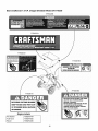
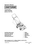
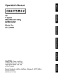
Operator's Manual
n
7.5 Horse Power
CHIPPER SHREDDER
Model No. 247.776350
CAUTION: Before
using this product,
read this manual and
follow all safety rules
and operating
instructions.
•
•
•
•
•
Safety
Operation
Maintenance
Storage
Espa5ol, p. 29
For answers to your questions about this product, call:
1-800-659-5917
Sears Craftsman Help Line
(5 am. - 5 pro., Mon. - Sat.)
Sears, Roebuck And Co., Hoffman Estates, IL 60179 U.S.A.
Visit our website: www.sears.com/craftsman
Printed in U.S.A.
FORM NO. 769-00831
(7/2003)
Content
Page
Content
Page
Warranty
2
Service and Adjustments
15
Safety
3
Storage
17
Assembly
6
Troubleshooting
18
Operation
8
Parts List
20
Maintenance
13
Limited Warranty on Craftsman
Chipper Shredder
For one (1) year from the date of purchase, if this Craftsman Equipment is maintained, lubricated, and tuned up
according to the instructions to the operator's manual, Sears will repair or replace free of charge any parts found to
be defective in material or workmanship. Warranty service is available free of charge by returning Craftsman
equipment to your nearest Sears Service Center. In-home warranty service is available but a trip charge will apply.
This Warranty applies only while this product is in the United States.
This Warranty does not cover:
Expendable items which become worn during normal use, such as spark plugs, air cleaners, belts, and oil
filters.
Tire replacement or repair caused by punctures from outside objects, such as nails, thorns, stumps, or glass.
Repairs necessary because of operator abuse, including but not limited to, damage caused by objects, such as
stones or metal debris, oversized stock, impacting objects that bend the frame or crankshaft, or over-speeding
the engine.
Repairs necessary because of operator negligence, including but not limited to, electrical and mechanical
damage caused by improper storage, failure to use the proper grade and amount of engine oil, or failure to
maintain the equipment according to the instructions contained in the operator's manual.
Engine (fuel system) cleaning or repairs caused by fuel determine to be contaminated or oxidized (stale). In
general, fuel should be used within 30 days of its purchase date.
Equipment used for commercial or rental purposes.
TO LOCATE THE NEAREST SEARS SERVICE CENTER OR TO SCHEDULE SERVICE, CONTACT SEARS AT
1-800-4-MY-HOME®.
This warranty gives you specific legal rights and you may also have other rights, which vary from state to state.
PRODUCT SPECIFICATION
Horsepower:
7.5 Horse Power
Model Number ....... ,2..4_,_
.7._-6.3-5Q...........................
Engine Oil Type
SAE 30
20 Ounces
Serial Number ...........................................................
3 Quarts
Date of Purchase ......................................................
Engine Oil Capacity
Fuel Capacity:
Spark Plug
Spark Plug Gap
Champion QC-12YC
.030"
Record both serial number and date of purchase and
keep in a safe place for future reference.
WARNING:
This symbol points out important safety instructionswhich, if not followed, could
endanger the personal safety and/or property of yourself and others. Read and follow all instructions in
this manual before attempting to operate this machine. Failure to comply with these instructions may
result in personal injury. When you see this symbol - heed its warning.
WARNING: Engine Exhaust, some of its constituents, and certain vehicle
components contain or emit chemicals known to State of California to cause cancer
and birth defects or other reproductive harm.
DANGER:
This machine was built to be operated according to the rules for safe operation in this
manual. As with any type of power equipment, carelessness or error on the part of the operator can
result in serious injury. This machine is capable of amputating hands and feet and throwing objects.
Failure to observe the following safety instructions could result in serious injury or death.
TRAINING
PREPARATION
1.
1.
2.
3.
4.
5.
6.
7.
8.
Read, understand, and follow all instructionson the
machine and in the manual(s) before attempting to
assemble and operate. Keep this manual in a safe
place for future and regular reference and for
ordering replacement parts.
Be familiar with all controls and their proper
operation. Know how to stop the machine and
disengage them quickly.
Never allow children under 16 years old to operate
this machine. Children 16 years old and over
should read and understand the operation
instructions and safety rules in this manual and
should be trained and supervised by a parent.
Never allow adults to operate this machine without
proper instruction.
Keep bystanders, helpers, pets, and children at
least 75 feet from the machine while it is in
operation. Stop machine if anyone enters the area.
Never run an engine indoors or in a poorly
ventilated area. Engine exhaust contains carbon
monoxide, an odorless and deadly gas.
Do not put hands and feet near rotating parts or in
the feeding chambers and discharge opening.
Contact with the rotating impeller can amputate
fingers, hands, and feet.
Never attempt to unclog the chipper chute or
discharge opening, remove or empty bag, or
inspect and repair the machine while the engine is
running. Shut the engine off and wait until all
moving parts have come to a complete stop.
Disconnect spark plug wire and keep away from
spark plug.
2.
3.
4.
5.
Thoroughly inspect the area where the equipment
is to be used. Remove all rocks, bottles, cans, or
other foreign objects which could be picked up or
thrown and cause personal injury or damage to the
machine.
Always wear safety glasses or safety goggles
during operation or while performing an adjustment
or repair, to protect eyes. Thrown objects which
ricochet can cause serious injury to the eyes.
Wear sturdy, rough-soled work shoes and closefitting slacks and shirts. Loose fitting clothes or
jewelry can be caught in movable parts. Never
operate this machine in bare feet or sandals. Wear
leather work gloves when feeding material in the
chipper chute.
Before starting, check all bolts and screws for
proper tightness to be sure the machine is in safe
working condition. Also, visually inspect machine
for any damage at frequent intervals.
To avoid personal injury or property damage use
extreme care in handling gasoline. Gasoline is
extremely flammable and the vapors are explosive.
Serious personal injury can occur when gasoline is
spilled on yourself or your clothes which can ignite.
Wash your skin and change clothes immediately.
a. Use only an approved gasoline container.
b. Extinguish all cigarettes, cigars, pipes, and
other sources of ignition.
c. Never fuel machine indoors.
d. Never remove gas cap or add fuel while the
engine is hot or running.
e. Allow engine to cool at least two minutes
before refueling.
f. Never over fill fuel tank. Fill tank to no more
than 1/2 inch below bottom of filler neck to
provide space for fuel expansion.
g. Replace
gasolinecapandtightensecurely.
h. If gasolineisspilled,wipeitofftheengine
andequipment.
Movemachine
toanother
area.Wait5 minutesbeforestartingthe
engine.
i. Neverstorethemachineorfuelcontainer
insidewherethereis anopenflame,spark,
orpilotlight(e.g.furnace,waterheater,
spaceheater,clothesdryer,etc.)
j. Toreduceafirehazard,keepmachine
free
ofgrass,leaves,orotherdebrisbuild-up.
Cleanupoilorfuelspillageandremoveany
fuelsoakeddebris.
k. Allowmachine
tocootatleast5minutes
beforestoring.
9.
10.
11.
12.
13.
14.
15.
OPERATION
1.
2.
3.
4.
5.
6.
7.
8.
Do not put hands and feet near rotating parts or in
the feeding chambers and discharge opening.
Contact with the rotating impeller can amputate
fingers, hands, and feet.
Before starting the machine, make sure the chipper
chute, feed intake, and cutting chamber are empty
and free of all debris.
Thoroughly inspect all material to be shredded and
remove any metal, rocks, bottles, cans, or other
foreign objects which could cause personal injury
or damage to the machine.
If it becomes necessary to push material through
the shredder hopper, use a small diameter stick. Do
not use your hands or feet.
If the impeller strikes a foreign object or if your
machine should start making an unusual noise or
vibration, immediately shut the engine off. Allow the
impeller to come to a complete stop. Disconnect
spark plug wire and keep away from spark plug.
Perform the following steps:
a. Inspect for damage.
b. Repair or replace any damaged parts.
c. Check for any loose parts and tighten to
assure continued safe operation.
Do not allow an accumulation of processed
material to build up in the reduction chamber. This
can prevent proper discharge and result in kickback
of material through the feed opening.
Do not attempt to shred or chip material larger than
specified on the machine or in this manual.
Personal injury or machine damage could result.
Never attempt to unclog the chipper chute or
discharge opening while the engine is running.
Shut the engine off, wait until all moving parts have
stopped, disconnect spark plug wire and keep
away from spark plug before clearing debris.
WARNING:
16.
Never operate without the shredder hopper,
chipper chute, or discharge chute properly attached
to the machine. Neverinstalt or remove debris
collection bag while the engine is running.
Keep all guards, deflectors and safety devices in
place and operating properly.
Keep your face and body back and to the side of
the chipper chute while feeding material into the
machine to avoid accidental kickback injuries.
Never operate this machine without good visibility
or light.
Do not operate this machine on a paved, gravel or
non-level surface.
Do not operate this machine while under the
influence of alcohol or drugs.
Muffler and engine become hot and can cause a
burn. Do not touch.
Never pick up or carry machine while the engine is
running.
MAINTENANCE
AND STORAGE
1.
Never tamper with safety devices. Check their
proper operation regularly.
2. Check bolts and screws for proper tightness at
frequent intervals to keep the machine in safe
working condition. Also, visually inspect machine
for any damage and repair, if needed.
3. Before cleaning, repairing, or inspecting, stop the
engine and make certain the impeller and all
moving parts have stopped. Disconnect spark plug
wire and keep away from spark plug to prevent
unintended starting.
4. Do not change the engine governor settings or
overspeed the engine. The governor controls the
maximum safe operating speed of the engine.
5. Maintain or replace safety and instruction labels, as
necessary.
6. Follow this manual for safe loading, unloading,
transporting, and storage of this machine.
7. Never store the machine or fuel container inside
where there is an open flame, spark or pilot light
such as a water heater, furnace, clothes dryer, etc.
8. Always refer to the operator's manual for proper
instructions on off-season storage.
9. If the fuel tank has to be drained, do this outdoors.
10. Observe proper disposal laws and regulations for
gas, oil, etc. to protect the environment.
- YOUR RESPONSIBILITY: Restrict the use of this power machine to persons who read,
understand and follow the warnings and instructions in this manual and on the machine.
Look For Relevant Emissions Durability Period and
Air Index Information On Your Engine Emissions Label
Engines that are certified to meet the California Air Resources Board (CARB) Tier 2 Emission Standards must
display information regarding the Emissions Durability Period and the Air Index. Sears, Roebuck and Co., U.S.A.
makes this information available to the consumer on our emission labels.
The Emissions Durability Period describes the number of hours of actual running time for which the engine is certified to
be emissions compliant, assuming proper maintenance in accordance with the Operating & Maintenance Instructions.
The following categories are used:
Moderate:Engine
Intermediate:Engine
Extended:Engine
is certified to be emission compliant for 125 hours of actual engine running time.
is certified to be emission compliant for 250 hours of actual engine running time.
is certified to be emission compliant for 500 hours of actual engine running time.
For example, a typical walk-behind lawn mower is used 20 to 25 hours per year. Therefore, the Emissions
Period of an engine with an intermediate
rating would equate to 10 to 12 years.
Durability
The Air Index is a calculated number describing the relative level of emissions for a specific engine family. The lower the
Air Index, the cleaner the engine. This information is displayed in graphical form on the emissions label.
After July 1, 2000, Look For Emissions Compliance
Engine Emissions Compliance
Label
Period On
After July 1, 2000 certain Sears, Roebuck and Co., U.S.A. engines will be certified to meet the United States
Environmental Protection Agency (USEPA) Phase 2 emission standards. For Phase 2 certified engines, the Emissions
Compliance Period referred to on the Emissions Compliance label indicates the number of operating hours for which the
engine has been shown to meet Federal emission requirements. For engines less than 225 cc displacement, Category C
= 125 hours, B = 250 hours and A = 500 hours. For engines of 225 cc or more, Category C = 250 hours, B = 500 hours and
A = 1000 hours.
The displacement
engines of Model Series 120000 is 206 cc.
This is a generic representation of the emission label typically found on a certified engine.
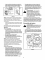
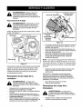
IMPORTANT:This unit is shipped without gasoline or
oil in the engine, After assembly, see OPERATION
section of this manual for proper fuel and engine oil fillup.
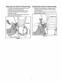
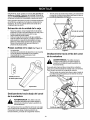
Pull the spring latch upward and gently pivot the
chipper chute down until it clicks into the lock rod.
See Figure 2.
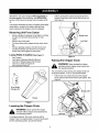
This Chipper Shredder has been completely assembled
at the factory, except for the debris collection bag,
which is stowed in the chipper chute for shipping.
Removing Unit From Carton
Remove staples, break glue on top flaps or cut tape
at carton end and peel along top flap to open
carton.
Remove any loose parts.
Cut down along carton edges and lay carton down
flat.
Remove packing material. Lift unit from the rear
and discard bottom pad. Roll unit out of carton.
Check carton thoroughly for loose parts.
Loose Parts In Carton (SeeFigure1)
One
One
One
One
One
Tamper
Debris Collection Bag (Not Shown)
Pair of Safety Glasses (Not Shown)
20-oz. Bottle of Engine Oil
Operator's Manual
Figure 2
Raising the Chipper
Chute
shredder
without
chipper
chutethe
lowered
WARNING:
Never
operate
chipperinto
the operating position.
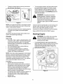
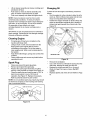
For convenience when storing, the chipper chute can
be pivoted upward. To do so, proceed as follows:
Pull the lock rod outward and pivot the chipper
chute upward until it clicks into the spring latch. See
Figure 3.
20-oz. Bottle
of Engine Oil
Latch
Tamper
Figure 1
Lowering the Chipper Chute
shredder without
chipper
chutethe
lowered
WARNING:
Never
operate
chipperinto
the operating position.
For shipping reasons, the unit is cartoned with its
chipper chute in a raised position.To pivot it downward,
into the operating position, proceed as follows:
Lock Rod"
Figure 3
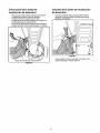
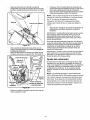
Attaching The Debris Collection Bag
To attach the bag, place the opening of the bag
completely over the discharge chute.
Position the bag so that the wing knobs which
secure the discharge chute to the housing are
completely covered.
Pull on the drawstrap until the bag is tight around
discharge chute. See Figure 4.
Emptying the Debris Collection
Bag
Squeeze the locking buckle to release the bag's
drawstrap before loosening it from the discharge
chute. See Figure 5
Empty the bag and reattach to the discharge chute
opening. Refer to Figure 4.
Locking Buckle
J
4ousing
Figure 5
Debris Collection Bag
Figure 4
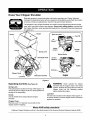
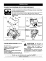
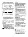
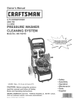
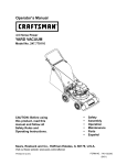
Know Your Chipper Shredder
Read this operator's manual and safety rules before operating your Chipper Shredder.
Compare the illustrations below with your equipment to familiarize yourself with the location
of various controls and adjustments. Save this manual for future reference.
The operation of any Chipper Shredder can result in foreign objects being thrown into the
eyes, which can result in severe eye damage. Always wear safety glasses, provided with
the Chipper Shredder, while operating this equipment or while performing any adjustments
or repairs on it.
Hopper
Handle
Spark Plug Wire
Air
Cleaner
Chok_
Control
Tamper
Throffie
Lever
Spring Latch
Starter Handle
Discharge Chute
Oil Fill /
Muffler
Oil Drain
Chipper Chute
Lock Rod
Reduction Chamber
Engine
j,
Figure 6
Operating
Controls
WARNING:
Never operate the chipper
shredder with the chipper chute in the raised
position. Release the spring latch to lower the
chipper chute into the operating position
before starting the engine.
(See Figure 6)
Spring Latch
The spring latch is located on the top of the hopper. It is
used to secure the chipper chute in a raised position for
storage or for transporting.
Lock Rod
The lock rod is located on the chipper chute support. It
is used to release or lock the chipper chute in a lowered
position for operation.
Handle
Use the handle when transporting the chipper
shredder.
Chipper Chute
Branches up to 3" in diameter may be fed into the
chipper chute for chipping.
Meets ANSI safety standards
Craftsman Chipper Shredders conform to the safety standard of the American National Standards Institute (ANSi).
8
WARNING:
Use the tamper
Tamper
to assist in feeding branches into the
,_
When moving throttle control
lever, be careful of heated surfaces on muffler
guard.
A
,_.
CAUTION:
chipper chute.
Hopper
Leaves, twigs and branches up to 1/2-inch in
diameter may be placed into the hopper for shredding.
IMPORTANT: Never place branches with a diameter
greater than 1/2-inch in the hopper. Doing so can result
in serious damage to your unit's shredder blade, flails
or impeller.
Never stop the engine by
moving the choke lever into the CHOKE
position. Backfire, fire or engine damage
could result.
Gas And Oil Fill-up
Engine
Oil (one 20-oz. bottle included)
NOTE: In the state of California, the 110000 series
engines covered in this manual are certified by the
California Air Resources Board to meet emissions
standards for 250 hours. Such certification does not
IMPORTANT:The chipper shredder is shipped without
oil in the engine.
grant the purchaser, owner or operator of this engine
any additional warranties with respect to the
performance or operational life of this engine. This
engine is warranted solely according to the product and
emissions warranties stated elsewhere in this manual.
Bore
2-11/16 in. (68 mm)
Stroke
2-13/64 in. (56 mm)
Displacement
12.48cu. in.(206cc)
IMPORTANT:For practical operation, the horsepower
loading should not exceed 85% of rated horsepower.
Engine power will decrease 3-1/2% for each 1,000 feet
(300 meters) above sea level and 1% for each 10° F
(5.6 ° C) above 77 ° F (25 ° C). Engine will operate
satisfactorily at an angle up to 15 degrees.
Throttle Lever
Type of Oil
1. Refer to the chart below for proper grade of oil.
2. Use a high quality detergent oil classified "For
service SF, SG,SH, SJ" or higher.
3. Do not use special additives.
Synthetic off meeting ILSAC GF-2, API certification and
API service symbol with "SJ/CF Energy Conserving" or
higher is an acceptable oil at all temperatures. Use of
synthetic oil does not alter required oil change intervals.
SAE Viscosity Grades
30
_5W-30,
i
L
10W-30
I
°F -20"
O°'
20"
40°'
60°'
80°'
100°'
Starting temperature rangeanticipated before next oil change
The throttle lever controls the engine speed and stop
function.
Choke Control
The choke control closes the choke plate on the
carburetor and aids in starting a cold engine.
Starter Handle
The starter handle is located on the engine. Pull the
starter handle to start engine.
Stopping Engine
Move throttle control lever to STOP position. See
Figure 7.
* CAUTION: Air cooled engines run hotter than automotive
engines. The use of non-synthetic multi-viscosity oils (5W30, 10W-30 etc.) in temperatures above 40°F will result in
higher than normal oil consumption. When using a multiviscosity oil, check oil level more frequently.
** CAUTION: SAE 30 oil, if used below 40°F, will result in
hard starting and possible engine bore damage due to
inadequate lubrication.
Remove oil fill dipstick.
With the Chipper Shredder on level ground, use a
funnel to fill engine with oil to FULL mark on
dipstick. Capacity is 20 oz. (0.6 liter). Be careful
not to overfill. Overfilling will cause the engine to
smoke profusely and will result in poor engine
performance. The oil bottle packaged with your
Chipper Shredder contains 20 oz. of oil.
Before operating the chipper shredder, check the
oil level as follows:
Wipe the dipstick with a clean cloth and reinsert it in
the oil fill tube.
Figure 7
Tighten the dipstick before removing it and check
the oil fill level. See Figure 8.
To avoid engine problems, the fuel system should
be emptied before storage for 30 days or longer.
Drain the gas tank, start the engine and let it run
until the fuel lines and carburetor are empty. Use
fresh fuel next season. See STORAGE section for
additional information.
Full
WARNING:
Figure 8
NOTE: Do not allow the dipstick to rub along the inside
walls of the oil fill tube when removing it. Doing somay
result in a false dipstick reading.
Check oil level three times prior to starting engine to
be certain you've gotten an accurate dipstick
reading.
IMPORTANT:Running the engine with too little oil can
result in permanent engine damage.
Use extreme care when
handling gasoline. Gasoline is extremely
flammable and the vapors are explosive.
Never fuel machine indoors or while the
engine is hot or running. Extinguish
cigarettes, cigars, pipes, and other sources of
ignition.
Check the fuel level periodically to avoid running out of
gasoline while operating the chipper shredder. If the
unit runs out of gas while operating, it may be
necessary to unclog the unit before it can be restarted.
Refer to SERVICE AND ADJUSTMENT section.
Starting Engine
WARNING:
The muffler and surrounding
area will be hot if the engine has been
running. Use caution and protect your hands if
working near the muffler.
Gasoline
Type of Fuel
Use clean, fresh, regular unleaded gasoline with
a minimum of 85 octane. Fresh fuel prevents gum
from forming in the fuel system or on essential
carburetor parts. Purchase fuel in quantity that can
be used within 30 days.
Do not use gasoline which contains Methanol.
Do not mix oil with gasoline.
Your chipper shredder's engine is certified to
operate on gasoline. Exhaust Emission Control
System: EM (Engine Modifications).
If not already attached, attach spark plug wire to
spark plug. Make certain the rubber boot on the end
of the spark plug is snapped securely over the
metal tip on the spark plug. Refer to Figure 9 for
spark plug wire location.
Spark Plug Wire
NOTE: Some fuels, called oxygenated or reformulated
gasoline, are gasoline blended with alcohols or ethers.
Excessive amounts of these blends can damage the
fuel system or cause performance problems. If any
undesirable operating symptoms occur, use gasoline
with a lower percentage of alcohol or ether.
Fuel Fill-up
Remove fuel cap from the fuel tank.
Make sure the container from which you will pour
the gasoline is clean and free from rust or foreign
particles. Never use gasoline that may be stale
from long periods of storage in itscontainer.
Gasoline that has been sitting for any period longer
than four weeks is considered stale.
Figure 9
The fuel tank has a capacity of three (3) quarts. Fill
fuel tank with clean, fresh, unleaded regular,
unleaded premium or reformulated automotive
gasoline only.
Replace fuel cap.
10
MovechokelevertoCHOKEposition.(Awarm
enginemaynotrequirechoking).
SeeFigure10.
Avoid shredding fibrous plants such as tomato
vines until they are thoroughly dried out. Fresh
vines do not shred well and tend to wrap
themselves around the impeller and flails.
Place reasonable amounts of debris into the hopper
at a time. Do not overload the hopper.
Allow the material in the hopper to be drawn into the
blades and shredded before adding additional
debris to the hopper. Failure to due so may result in
a clogged hopper, clogged discharge chute or a
stalled engine.
Avoid placing twigs longer than 24 inches into the
hopper. Twigs longer than 24 inches may result in a
clogged hopper.
CHOKE
Figure 10
Move throttle control lever to FAST (rabbit) position.
See Figure 11.
IMPORTANT:Never place branches with a diameter
greater than 1/2-inch in the hopper. Doing so can result
in serious damage to your unit's shredder blade, flails or
impeller.
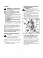
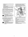
Clearing
the Hopper
Should the hopper become clogged with debris during
operation, proceed as follows:
Grasp the handle with both hands and gently
agitate the chipper shredder to help loosen debris,
drawing it into the impeller.
If the clog does not clear, proceed as follows:
Figure 11
Grasp the starter handle and pull the rope out
slowly until resistance is felt. When it becomes
slightly harder to pull the rope, slowly allow the rope
to recoil. Then pull rope with a rapid, continuous,
full arm stroke. Keep a firm grip on starter handle.
Repeat the previous steps until engine starts. When
engine starts, move choke control gradually toward
the RUN position until the engine is running
smoothly.
Stop engine.
Use your hands to remove any debris found near
the top of the hopper.
Use a branch (or other available device, i.e.
broomstick) to dislodge debris located toward the
base of the hopper.
Restart engine.
NOTE: If you're unable to pull the starter rope as a
result of accumulated debris near the impeller, follow
instructions under the heading Cleaning the
Reduction Chamber.
NOTE: A "clanky" noise may be heard when pulling
the starter rope. It is completely normal and does NOT
indicate a malfunction of any kind. The noise is caused
by the flails (part of the shredding mechanism) pivoting
on the chipper shredder's impeller as it rotates.
Allow the rope to recoil slowly.
WARNING:
Never run the engine indoors
or in a poorly ventilated area. Engine exhaust
contains carbon monoxide, an odorless and
deadly gas.
Shredding
Yard waste such as leaves and pine needles can be
placed in the hopper for shredding. After material has
been processed by the shredder blade and flails, it will
be forced out of the discharge chute, and, if attached,
into a debris collection bag. Observe the following
guidelines when shredding yard debris:
Never attempt to shred material other than normal
yard debris (leaves, twigs, pine cones, etc.).
11
Chipping
dl_
Disconnect spark plug wire and keep away from
spark plug. Refer to Page 15.
WARNING:
The muffler and surrounding
area will be hot if the engine has been
running. Use caution and protect your hands if
working near the muffler.
shredder
without
chipper
chutethe
lowered
WARNING:
Never
operate
chipperinto
the operating position.
Branches up to 3" in diameter can be fed into the
chipper chute. See Figure 6.Observe the following
guidelines when chipping branches:
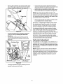
Remove the two wing knobs on either side of the
discharge chute and pivot the discharge chute
upward. See Figure 12.
Remove the hairpin clip from the clevis pin which
extends through the housing and shredder screen.
See Figure 12. Retain the clevis pin and hairpin
clip.
Keep both hands firmly on the branch as you feed it
into the chipper chute.
Never feed more than one branch into the chipper
chute at a time.
Never feed anything other than branches (or wood)
into the chipper chute.
Use the tamper to assist in feeding branches into
the chipper chute.
Apply intermittent pressure (force, in short pulses)
while feeding larger (2- 3-inch diameter) branches
into the chipper chute, to avoid bogging or stalling
the engine.
Discharge
Chute
Shredder
Screen
Housing
IMPORTANT: Never feed branches with a diameter
greater than three (3) inches into the chipper chute.
Doing so can result in serious damage to your unit's
chipper blades, flails or impeller.
NOTE: For best performance, always operate the unit
with sharp chipper blades. If a noticeable loss in
performance is encountered while chipping branches,
the chipper blades should be replaced.
Chamber
Cleaning
the Reduction Chamber
Figure 12
WARNING:
The impetler's shredder blade
and chipper blades are sharp. Wear leather
work gloves to protect your hands when
cleaning out the reduction chamber.
Pivot the shredder screen upward and clean the
surrounding area by scraping away debris.
Confirm that the spark plug wire is disconnected
and away from spark plug.
Pull on the starter rope two-to-three times to purge
any remaining debris from the reduction chamber
When the area is cleaned, pivot the shredder
screen downward and re-secure with the clevis pin
and hairpin clip removed earlier.
Reattach the debris collection bag to the discharge
chute, if desired.
If the reduction chamber becomes clogged with debris,
the shredder screen can be pivoted upward so that you
can clean the surrounding area. To do so, proceed as
follows:
Stop the engine and wait untill all moving parts
have come to a complete stop.
12
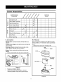
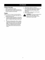
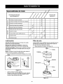
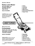
CustomerResponsibilities
MAINTENANCE
_
SCHEDULE
no
,_
,,o
,b
_,_
._e6 _e.A ._e6
_
_
_
me
oe
o_
_
SERVICE
_o<
DATES
,_
Lube Spring Latch
a
O
Lube Chipper Chute Hinge
,q_
Lube DischargeChute
q_
Inspect Chipper Blades
_
Inspect Shredder Blade
,:_
Check Oil Level
Wz
Change Oil
_
Clean Air Filter Precleaner
_/7
Clean Engine
,q_
,_
<_
Check Spark Plug
4_
_
d
Lubrication
Air Cleaner
Spring Latch: Lubricate the latch with light oil once a
season
Clean air cleaner's precteaner every 25 hours under
normal conditions. To remove air cleaner, proceed as
follows:
Chipper Chute Hinge: Lubricate the hinge with light oil
once a season.
Remove knob and cover. See Figure 14.
Discharge Chute: Lubricate the pivot points on the
chute deflector with light oil once a season.
I_'_"
Engine: Check engine oil level before each use as
follows:
Remove the dipstick and wipe with a clean cloth.
Full
Knob
i
4b
Cover_
_
Cartridge
Pre-cleaner
Air Cleaner
Stud
Figure 13
Replace and tighten dipstick.
Remove and check the oil fill level. Add oil if
necessary (Refer to Page 9 for proper oil type).
Base
Figure 14
13
Changing
Lift air cleaner assembly (air cleaner cartridge and
precleaner) off stud.
Push clean (or new) air cleaner assembly onto
stud. Air cleaner must fit securely on base.
Push cover squarely onto base and tighten knob.
Oil
To drain oil from the engine's crankcase, proceed as
follows:
Run the engine for a few minutes to allow the oil to
warm up. Warm oil flows more easily and will carry
away more impurities when draining oil.
Position the chipper shredder on level surface and
place an appropriate receptacle with a capacity of
at least one quart beneath the oil drain tube. See
Figure 16.
NOTE: Clean pre-cleaner every few hours under
extremely dusty conditions. To clean pro-cleaner,
separate it from cartridge and wash in liquid detergent
and water. Air dry thoroughly. Do not oil pro-cleaner.
Re-assemble dry pre-cleaner onto clean
cartridge.Replace
the air cleaner cartridge once a
season.
IMPORTANT:Do not use pressurized air or solvents to
clean cartridge. Pressurized air can damage cartridge.
Solvents will dissolve cartridge.
Cleaning
Engine
Promptly wipe off any fuel or oil spilled on the
machine with clean cloth.
Using a brush or cloth, remove debris from the
finger guard on the engine daily to prevent
overheating of the engine. Do not use water to
clean engine parts. Water could contaminate the
fuel system.
Keep the throttle linkage, springs and controls free
of debris.
Clean muffler area and remove any debris before
operating the unit.
Oil Drain Tube
Figure 16
Remove the oil dipstick.
Use a 3/8" wrench to unthread the oil plug from the
drain tube, allowing the used oil to flow out.
Replace the oil plug and add 20 oz. of new oil
(Refer to Page 9 for proper oil type). Do NOT
overfill.
Spark Plug
Clean area around the spark plug base.
Remove and inspect the spark plug.
Replace the spark plug if electrodes are pitted,
burned, or the porcelain is cracked. See Figure 15.
Clean the spark plug and reset the gap to .030" at
least once a season or every 100 hours of
operation. See Figure 15. Replace if necessary.
Refer to parts list section for part number.
Replace dipstick and check oil level (Refer to Page
9).
NOTE: Do not sandblast spark plug. Spark plug shou/d
be cleaned by scraping or wire brushing and washing
with a commercial solvent.
,030" (0,76 mm)
Figure 15
14
WARNING:
Always stop engine,
disconnect spark plug wire and keep away
from spark plug, before performing any
service or adjustments on your machine.
Disconnecting
Chipper Blade
Lock Washer & Nut
Spark Plug
WARNING:
The muffler and surrounding
area wilt be hot if the engine has been
running. Use caution and protect your hands if
working near the muffler.
Locate the spark plug wire between the muffler and air
cleaner. See Figure 17.
Muffler
Impeller
Spark Plug Wire
Hex Bolts & .__t
Saddle Washers
_
Screw
Figure 18
Remove the chipper chute by removing three hex
nuts and washers which secure it to the impeller
housing. See Figure 18.
Rotate the impeller by hand until one of the two
chipper blades is visible through the impeller
housing opening.
Remove the blade by removing the internal hex
screws, lock washers and hex nuts which secure it
to the impeller. Retain the hardware.
Air Cleaner
NOTE: Use a 3/16" hex key (Allen) wrench on the
outside of the blade and a I/2" box (or socket) wrench
on the inside of the impeller. See Figure 18. Hold the
Allen wrench stationary and rotate the box (or socket)
wrench to loosen the nut.
Figure 17
Disconnect the spark plug wire by gently pulling the
rubber boot from the spark plug. Keep the wire away
from spark plug while servicing your chipper shredder
to prevent accidental starting of the engine.
Replacing the Chipper
,_
Install a replacement blade (Part No. 742-0544)
with the hardware removed earlier.
IMPORTANT:Make certain blades are reassembled with
the sharp edge outward (toward the chipper chute).
Torque hardware to between 20 ft-lbs and 25 ft-lbs.
Blades
are
sharp. WearThe
leather
work gloves
WARNING:
impetler's
chipper toblades
protect your hands.
To replace the other blade, rotate the impeller to
expose the second blade and repeat the steps
above.
Stop the engine and make certain the chipper
shredder has come to a complete stop.
Disconnect spark plug wire and keep away from
spark plug.
Pivot the shredder screen upward as instructed
under the heading Cleaning the Reduction
Chamber.
Remove the chipper chute support brace from the
frame by removing the two hex bolts and saddle
washers which secure it. See Figure 18.
Replacing the Shredder Blade
,_
are
sharp. WearThe
leather
work gloves
WARNING:
impeller's
chipper toblades
protect your hands.
Stop the engine and make certain that all moving
parts have come to a complete stop.
15
Remove the two flange nuts (and hex bolts) which
secure the hopper support bracket to the impeller
housing. Retain the hardware. See Figure 19.
Insert a piece of wood into the discharge chute
opening to stabilize the impeller and prevent it from
rotating when removing the shredder blade.
Remove the two internal hex screws which secure
the shredder blade to the impeller. See Figure 20.
NOTE: Use a 3/16" hex key (Allen) wrench on the
outside of the shredder blade and a 1/2" box (or socket)
wrench on the inside of the shredder blade. See Figure
20. Hold the Allen wrench stationary and rotate the box
(or socket) wrench to loosen the nut.
Suppo_
Bracket_
Remove the hex bolt, lock washer, and flat washer
to completely free the shredder blade.
IMPORTANT: If sharpening the blade for reuse, follow
the original angle of grind as a guide. It is extremely
important that each cutting edge receives an equal
amount of grinding to prevent an unbalanced blade.
An unbalanced blade will cause excessive vibration
when rotating at high speeds and may cause damage
to the unit. The blade can be tested for balance by
inserting a screwdriver through its center hole. Remove
metal from the heavy side until it is balanced evenly.
Figure 19
Pivot the shredder screen upward as instructed
under the heading Cleaning the Reduction
Chamber.
Remove the six flange nuts which secure the
hopper inlet guide to the impeller housing. See
Figure 20.
IMPORTANT: When reassembling the blade, tighten
center bolt to between 45 ft-lbs and 60 ft-lbs and the two
out bolts to between 20 ft-tbs and 25 ft-tbs.
Carburetor
Adjustment
The carburetor on this engine is low emission. It is
equipped with a non-adjustable idle mixture valve and
governed idle. Governed idle and top speed have been
set at the factory. If adjustment is required, see a Sears
Service Center.
Chute
NOTE: Engines operated at about 3000 to 5000 feet
(900 to 1500 meters) above sea level may require a
high altitude carburetor nozzle. If erratic performance is
observed, contact a Sears Service Center for cost to
install/purchase a high altitude carburetor nozzle, if
available.
Nuts
nlet
Guide
iHex Bolt, Lock Washer
& Flat Washer
Figure 20
Carefully separate the hopper assembly from the
impeller housing and set it aside.
16
Chipper
Shredder
Clean the equipment thoroughly.
Wipe equipment with an oiled rag to prevent rust.
Store unit in a clean, dry area. Do not store next to
corrosive materials such as fertilizer.
Engine
a.
4.
5.
Clean engine of surface debris, chaff or grass.
Store in a clean, dry area.
Do not store in same area as a
stove, furnace, water heater, or other
appliance that uses a pilot light or has a
device that can create a spark.
To prevent gum from forming in fuel system or on
essential carburetor parts:
if fuel tank contains oxygenated or reformulated
gasoline (gasoline blended with an alcohol or an
ether), run engine until it stops from lack of fuel,
or
b.
While engine is still warm, change oil.
Remove spark plug and pour about one (1) oz. (30
ml.) of engine oil into spark plug hole. Replace
spark plug and slowly pull the starter rope to
distribute oil.
WARNING:
Engines stored over 30 days need special attention.
1.
2.
3.
if fuel tank contains gasoline, either run engine
until it stops from lack of fuel, or add a gasoline
additive to the gas in the tank. If you use a gas
additive, run the engine for several minutes to
circulate the additive through the carburetor.
Then, engine and fuel can be stored up to 24
months.
17
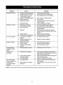
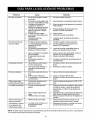
Problem
Engine fails to start
Engine runs erratic
Cause
1.
, 2.
3.
Remedy
Spark plug wire disconnected.
Fuel tank empty or stale fuel.
Throttle control lever not in
correct starting position.
1.
2.
3.
Connect wire to spark plug.
Fill tank with clean, fresh gasoline.
Move throttle lever to FAST position.
4.
5.
6.
Choke not in CHOKE position.
Engine not primed.
BIocked fuel system.
4.
5.
6.
7.
Faulty spark plug.
7.
Move choke to CHOKE position.
Prime engine.
See Sears Service Center to have fuel
system cleaned.
Clean, adjust gap, or replace.
1.
2.
3.
Spark plug wire loose.
Unit running on CHOKE.
Dirt in fuel system
1.
2.
Connect and tighten spark plug wire.
Move choke lever to OFF position.
3.
4.
Stale fuel.
4.
5.
6.
Dirty air cleaner.
Carburetor out of adjustment.
5.
6.
See Sears Service Center to have fuel
system cleaned.
See Sears Service Center to have fuel
system cleaned. Fill tank with clean, fresh
gasoline.
Clean or replace air cleaner.
See authorized service dealer.
1.
Loose parts or damaged
impeller.
Blade(s) damaged or not
properly sharpened.
1.
See Sears Service Center.
2.
Replace or sharpen blade(s).
,
Too much vibration
2.
Engine overheats
1.
2.
3.
Engine oil level low.
Dirty air cleaner.
Carburetor not adjusted
properly.
1.
2.
3.
Fill crankcase with proper oil.
Clean or replace air cleaner.
See Sears Service Center.
Occasional skip
(hesitates) at high
speed
1.
Spark plug gap too narrow.
1.
Adjust gap to.030" (0.76 mm)
Unit does not
discharge
1.
D!scharge chute clogged.
1.
2.
2.
3.
Foreign object lodged in
reduction chamber.
Lowengine RPM.
Stop engine immediately and disconnect
spark plug wire. Clean shredder screen and
inside of discharge opening.
Stop engine and disconnect spark plug wire.
Remove lodged object.
Always run engine at full throttle.
1.
Lowengine RPM.
1.
2.
Chipper blades or shredder
blade dull.
2.
Rate of discharge
slows considerably or
composition of
discharged material
changes.
3.
Always run engine with the throttle in the
FAST position.
Replace blades or see your Sears Service
Center.
NOTE: For repairs beyond the minor adjustments listed above, please contact your local Sears Service Center.
18
(Thispageapplicable
inthe U.S.A.andCanada
only.)
Sears, Roebuck and Co., U,S,A. (Sears), the California Air Resources Board (GARB)
and the United States Environmental Protection Agency (U.S. EPA)
Emission Control System Warranty Statement (Owner's Defect Warranty Rights and Obligations)
EMISSION
CONTROL
WARRANTY
COVERAGE
IS APPLICABLE
TO
CERTIFIED
CERTIFIED ENGINES PURCHASED IN CALIFORNIA
IN 1995 AND
THEREAFTER,
WHICH
ARE USED
IN CALIFORNIA,
AND TO
California
and United
States
MODEL YEAR 1997 AND LATER ENGINES
PURCHASED AND USED ELSEWHERE
AFTER JANUARYI,200f
IN CANADA).
Emission
Control
The California Air Resources Board (CARB), U.S. EPA and Sears are
pleased to explain the Emission Control System Warranty on your model
year 2000 and later small off*road engine (SORE). In California, new small
off-road engines must be designed, built and equipped to meet the State's
stringent anti-smog standards. Elsewhere in the United States, new nonroad, spark-ignition engines certified for model year 1997 and later must
meet similar standards set forth by the U.S. EPA. Sears must warrant the
Defects
Warranty
WHICH ARE
IN THE UNITED STATES (AND
Statement
emission control system on your engine for the periods of time listed below,
provided there has been no abuse, neglect or improper maintenance of
your small off-road engine, Your emission control system includes parts
such as the carburetor, air cleaner, ignition system, muffler and catalytic
converter, Also included may be connectors and other emission related
assemblies, Where a warrantable condition exists, Sears will repair your
small off*road engine at no cost to you including diagnosis, parts and labor.
Sears Emission Control Defects Warranty Coverage
Small off-road engines are warrantedrelative to emissioncontrol
below, If any covered part on your engine is defective, the part will be
parts defects for a pedod of two years, subject to provisions set forth
repaired or replaced by Sears,
Owner's Warranty Responsibilities
As the small off-road engine owner, you are responsible for the
performance of the required maintenance listed in your Operating and
Maintenance Instructions. Sears recommends that you retain all your
receipts covering maintenance on your small off-road engine, but Sears
cannot deny warranty solely for the lack of receipts or for your failure to
ensure the performance of all scheduled maintenance. As the small offroad engine owner, you should however be aware that Sears may deny
you warranty coverage if your small off-road engine or a part has failed due
to abuse, neglect, improper maintenance or unapproved modifications.
You are responsible for presenting your small off*road engine to an
Authorized Sears Service Dealer as soon as a problem exists. The
undisputed warranty repairs should be completed in a reasonable amount
of time, not to exceed 30 daysJf you have any questions regarding your
warranty rights and responsibilities, you should contact a Sears Service
Representative at 1--800--469--4663. The emission warranty is a defects
warranty. Defects are judged on normal engine performance. The warranty
is not related to an in-use emission test.
Sears Emission Control Defects Warranty Provisions
The following are specific provisions relative to your EmissionControl Defects Warranty Coverage. It is in addition to the Sears engine warranty for non*
regulated engines found in the Operating and Maintenance Instructions.
1.
Warranted Parts
Coverage under this warranty extends only to the parts listed below
(the emission control systems pads) to the extent these parts were
present on the engine purchased.
a. Fuel Metering System
• Cold stad enrichment system
3.
• Carburetor and internal parts
• Fuel Pump
b.
4.
Air Induction System
• Air cleaner
• Intake manifold
c.
Ignition System
• Spark plug(s)
d.
Catalyst System
• Catalytic conveder
• Magneto ignition system
5.
• Exhaust manifold
• Air injection system or pulse valve
e.
Miscellaneous Items Used in Above Systems
• Vacuum, temperature, posifion, time sensitive valves
and switches
• Connectors and assemblies
2.
Length of Coverage
Sears warrants to the initial owner and each subsequent purchaser
that the Warranted Parts shall be free from defects in materials and
workmanship which caused the failure of the Warranted Parts for a
period of two years from the date the engine is delivered to a retail
purchaser.
In the USA and Canada, a 24 hour hot line, 1-800-469--4663,
6.
NO Charge
Repair or replacement of any Warranted Part will be performed at no
charge to the owner, including diagnostic labor which leads to the
determination that a Warranted Part is defective, if the diagnostic
work is performed at an Authorized Sears Service Dealer. For
emissions warranty service contact your nearest Authorized Sears
Service Dealer as listed in the "Yellow Pages" under "Engines,
Gasoline," "Gasoline Engines," "Lawn Mowers," or similar category.
Claims and Coverage Exclusions
Warranty claims shall be filed in accordance with the provisions of the
Sears Engine Warranty Policy. Warranty coverage shall be excluded
for failures of Warranted Parts which are not original Sears parts or
because of abuse, neglect or improper maintenance as set forth in the
Sears Engine Warranty Policy. Sears is not liable to cover failures of
Warranted Parts caused by the use of add-on, non-original, or
modified pads.
Maintenance
Any Warranted Part which is not scheduled for replacement as
required maintenance or which is scheduled only for regular
inspection to the effect of "repair or replace as necessary" shall be
warranted as to defects for the warranty period. Any Warranted Part
which is scheduled for replacement as required maintenance shall be
warranted as to defects only for the period of time up to the first
scheduled replacement for that part. Any replacement part that is
equivalent in performance and durability may be used in the
performance of any maintenance or repairs. The owner is responsible
for the performance of all required maintenance, as defined in the
Sears Operating and Maintenance Instructions.
Consequential Coverage
Coverage hereunder shall extend to the failure of any engine
components caused by the failure of any Warranted Part still under
warranty.
has a menu of pre_recorded messages offering you engine maintenance information.
19
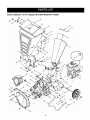
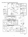
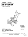
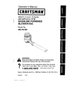
Sears Craftsman
7.5 H.P. Chipper Shredder
Model 247.776350
23
25
6
17
19
J
8
27
/
22
45
44
22
32
12
47_.
56
34
55
,\
,\
52
20
20
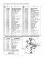
Sears Craftsman
Ref.
No.
Part No,
1,
2.
681-04006
681-04007
7.5 H.P. Chipper Shredder
Model 247.776350
Ref.
No.
Part Description
Upper Chipper Chute Assembly
Upper Chipper Chute Assembly
Hex Cap Screw, 1/4-20 x 1.25
Part No.
Part Description
30,
31.
32.
33_
34.
781-04027
781-04033
Hopper Support Bracket
Inlet Guide
681-0117
Inner Flail Housing Assembly
681-0184A
681-04002
Frame Assembly
35.
710-0157
Outer Flail Housing Assembly
Hex Cap Screw, 5/16-24 x .75
3.
710-0106
4.
5.
710-3013
712-3010
6.
712-3027
Hex Cap Screw, 1/4-20 x .5
Hex Nut, 5/16-18
Hex Lock Nut 1/4-20
7.
714-0104
Cotter Pin
36.
710-0502A
Hex Sems Screw, 3/8-16 x 1.25
8.
728-0175
Pop Rivet
732-0306A
735-0249
11.
736-0117
12.
13.
736-0242
736-0451
Compression Spring, .531 x 1.75
Chute Flap
Flat Washer
Bell Washer.340 ID x.872 OD
710-0825
710-3008
726-0211
Hex Cap Screw, 1/4-20 x 3.75
9.
10.
37.
38.
39.
40.
41.
736-0119
736-0170
42.
750-0793
Special Lock Washer, 5/16
Hinge Spacer, .265 x .380 x 1.66
14.
15.
747-04163
749-1004
Washer,.320 ID x.93 OD
Lock Rod
43_
681-0048
Knob, 5/16-18
Chipper Chute Support
44.
681-0094
Discharge Chute Assembly
16.
17.
78%04032
781-0633
Chipper Chute Hinge
45.
46.
711-0835
714-0149B
Clevis Pin, .50 x 4.62
internal Cotter Pin
18.
681-04011
47.
719-04070
Shredder Screen
19.
20.
710-0606
710-0805
48.
726-0214
Push Cap, 5/8
Oil Drain Tube
21.
22.
712-0431
712-3004A
49.
50.
737-0195
23.
24.
732-04167
736-0182
25.
"
Chute Flap Strip
Shredder Hopper Assembly
Hex Cap Screw, 1/4-20 x 1.5
Hex Cap Screw, 5/16-18 x 1.50
Flange Lock Nut, 3/8-16
,,
736-0366
738-0814
734-1600
Flange Lock Nut, 5/16-18
51.
Torsion Spring
52.
736-0326
Spring Washer, .50 x 1.0 x .022
Flat Washer, .50 x 1.0 x _0125
53.
54.
26.
738-0430
Shoulder Screw, 3/8-16, .50 x .685
55.
710-1254
736-0217
736-0247
27.
28.
749-04103
749-04104
Hopper Handle
56.
681-04009
29.
781-04007
Tube Support
Shredder Plate
Hex Cap Screw, 5/16-18 x.75
U-Nut, 5/16-18
Lock Washer, 5/16
Flat Washer, .625 x 1.0
Axle, 21.21"
Wheel, 10 x 2.5
Hex Cap Screw, 3/8-24 x 2.25
Lock Washer, 3/8
Flat Washer, .406 x 1.25
Impeller Assembly
(See below for Impeller Parts)
664-04023
Debris Collection Bag (Not Shown)
Ref.
No.
1.
681-0029
2.
3.
710-1054
711-0833B
4.
5.
712-0411
715-0166
6.
719-0329
7.
736-0119
8.
742-04050
Lock Washer, 5/16
Shredder Blade
9.
742-0544
Chipper Blade
10.
781-0735
Retainer Clip
Impeller Weldment
Machine Screw, 5/16-24 x 1.0
Clevis Pin, .496
Hex Lock Nut, 5/16-24
Spiral Pin, .156 x 1.0
Flail
2
NOTE: When ordering replacement painted parts,
add the applicable color code to the part number.
Sears Red:
0721
Oyster Grey:
0662
Powder Black: 0637
21
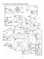
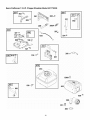
Sears Craftsman
7.5 H.P. Chipper Shredder
Model 247.776350
10
619 _
7
383
306
307
552
24
89 @
718
22
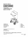
Sears Craftsman
7.5 H.P. Chipper Shredder
Model 247.776350
1091
365_
633A
D
633
163
137
276
127 _
130 %5
_
. _
977 CARBURETOR
GASKET
51 _
276Q
SET
163
968
467
633 O
121 CARBURETOR
OVERHAUL
633 G
KIT
967
633A G
104 °
127_
276
163
358 ENGINE GASKET
SET
717
961
971A_
12
_=_
163_
1022
868_
971 _
23
Sears Craftsman
2271
7.5 H.P. Chipper Shredder
Model 247.776350
562
_f
5z31
505
842
524 _
621 _
356
334
851
836A
190
832
836 %
24
Sears Craftsman
7.5 H.P. Chipper Shredder
Model 247.776350
597 _
456 _
689 _
/j.
_
i
65_
455
332 C
1070 _@
305
1095 VALVE GASKET
993
I 1320
RE,',_ACEMENT
ENGINE
I
I 1330
REPA,
RMANOA, 1
[ 48S.ORT
BLOCK
]
GASKET
_o
\
868
25
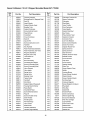
Sears Craftsman
Refi
No.
Part No.
1
2
699508
399269
3
299819
5
7
699486
698210
11
12
7.5 H.P. Chipper Shredder
Model 247.776350
Part Description
Ref.
No.
Part No.
Cylinder Assembly
Bushing/Seal Kit (Magneto Side)
Seal-Oil
121
122
125
696998
693749
698475
Carburetor Overhaul Kit
Head-Cylinder
127
691739
130
133
691181
398187
Plug-Welch
Valve-Throttle
693647
Gasket-Cylinder Head
Breather Tube
699485
Gasket-Crankcase
134
398188
Valve-Needle
13
699482
Screw (Cylinder Head)
137
693981
Gasket-Float Bowl
15
16
691686
699452
Plug-Oil Drain
Crankshaft
146
155
690979
698214
Part Description
Spacer-Carburetor
Carburetor
Float-Carburetor
18
699596
Cover-Crankcase
163
696979
Key-Timing
Plate-Cylinder Head
Gasket-Air Cleaner
20
21
692550
281658
Seal-Oil
186
692317
Connector-Hose
Cap-Oil Fill
187
693401
Line-Fuel (Molded)
22
699478
Screw (Crankcase Cover)
188
699479
Screw (Control Bracket)
23
699488
Flywheel
190
699220
Screw (Fuel Tank)
24
25
222698
499627
Key-Flywheel
192
694543
Adjustor-Rocker Arm
209
209A
692571
691278
692789
Piston Assembly (Standard)
Piston Assembly (.020" O/S)
26
499631
Ring Set (Standard)
219
693578
Spring-Governor
Spring-Governor
Gear-Governor
27
692786
691866
Ring Set (.020" O/S)
Lock-Piston Pin
220
222
691724
699589
Washer (Governor Gear)
Bracket-Control
28
499423
Pin-Piston
227
692573
Lever-Governor
29
690124
Rod-Connecting
238
691300
30
32
692562
691664
Connecting Rod Dipper
Screw (Connecting Rod)
271
276
694256
271716
Cap-Valve
Lever-Control
32A
695759
33
499642
Screw (Connecting Rod)
Valve-Exhaust
281
287
699639
699629
34
35
499641
691304
Valve-Intake
300
693593
36
691304
692194
304
305
306
699598
699480
693610
Housing-Blower
Screw (Blower Housing)
40
Spring-Valve
Spring-Valve
Retainer-Valve
45
46
690977
696813
Tappet-Valve
Camshaft
307
332
699483
699359
Screw (Cylinder Shield)
Nut (Flywheel)
48
699581
Short Block
333
695711
Armature-Magneto
51
55
692555
691422
Gasket-intake (2 Required)
Housing-Rewind Starter
334
337
699477
691043
Screw (Magneto Armature)
Plug-Spark
58
693389
Rope-Starter
356
695814
60
691951
Grip-Starter Rope
358
699638
Wire-Stop
Gasket Set
65
699228
Screw (Rewind Starter)
363
19069
89
95
691682
691636
690024
365
383
427
692568
19374
694255
Screw (Carburetor)
Wrench-Spark Plug
97
Plug-Oil
Screw (Throttle Valve)
Shaft-Throttle
98
104
398185
691242
108
692567
Kit-idle Speed
Pin-Float Hinge
Valve-Choke
445
455
456
697029
692591
692299
Filter A/C Cartridge
Cup-Flywheel
Pawl Friction Plate
109
693628
Shaft-Choke
459
281505
Ratchet Pawl
117
118
698344
694176
Jet-Main (Standard)
Jet-Main (High Altitude)
467
504
691668
694254
Knob-Air Cleaner
Washer Set
26
Washer-Sealing
Plate-Trim
Screw (Dipstick Tube)
Muffler
Shield-Cylinder
Flywheel Puller
Nut (Control Bracket)
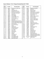
Sears Craftsman
Refi
No.
Part No.
595
523
691251
693618
524
552
562
597
7.5 H.P. Chipper Shredder
Model 247.776350
Ref.
No.
Part No.
Nut (Governor Control Lever)
847
693617
281379
Dipstick
Seal-Dipstick Tube
868
875
692044
697030
692346
Bushing-Governor
883
691893
Gasket-Exhaust
691112
691696
Bolt (Governor Control Lever)
Screw (Pawl Friction Plate)
914
914A
699481
692557
Screw (Rocker Cover) (Bottom)
Screw (Rocker Cover) (Top)
601
95162
693394
Clamp-Hose
Rewind Starter
914B
957
697551
694261
Screw (Rocker Cover)
608
613
615
699209
692576
Screw (Muffler)
Governor Shaft Retainer
961
967
698304
273356
Screw (Air Cleaner Bracket)
Filter-Pre Cleaner
616
692547
Crank-Governor
968
693460
Cover-Air Cleaner
619
621
699230
692310
Screw (Cylinder Head)
632
693408
Part Description
Crank
Switch-Stop
Part Description
Dipstick/Tube Assembly
Seal-Valve
Base-Air Cleaner
Cap-Fuel Tank
971
690349
Screw (Air Cleaner Base)
971A
94929
972
975
694260
493640
Screw (Air Cleaner Base)
Tank-Fuel
633
693867
Spring/Link Mechanical Governor
Choke/Throttle Shaft Seal (Throttle)
633A
691321
Choke/Throttle Shaft Seal (Choke)
977
697001
Gasket Set-Carburetor
635
663
805529
699206
Boot-Spark Plug
Screw (Control Panel)
993
1005
694088
692592
668
694257
Spacer
1019
690035
Gasket-Cylinder
Fan-Flywheel
Label Kit
689
692
691855
690572
693462
1022
1023
1026
691890
499924
693517
Gasket-Rocker Cover
Cover-Rocker
717
Spring-Friction
Spring-Detent (Choke)
Air Cleaner Bracket
718
690959
Pin-Locating
1029
691230
Rocker Arm
741
742
695087
692564
Gear-Timing
1095
698215
692566
1034
1036
691343
697004
Gasket Set-Valve
Push Rod Guide
746
Ring-Retaining
Gear-Idler
773
694258
Retainer
1070
699201
Screw (Flywheel Fan)
830
832
694544
693583
Stud-Rocker Arm
Guard-Muffler
1210
1211
498144
498144
Pulley/Spring Assembly (Pulley)
Pulley/Spring Assembly (Spring)
836
699203
Screw (Muffler Guard)
1329
121312-0145
836A
699632
Screw (Muffler Guard)
1330
272147
851
493880
Spark Plug Terminal
27
Bowl-Float
Head Plate
Rod-Push
Emission Label
Replacement Engine
Repair Manual
Sears Craftsman
7.5 H.P. Chipper Shredder
Model 247.776350
777S32258
[]
777D07574
/
777S32272
777S30189
ASSEMBLECHUTE DEFLECTOR
TO THiS UNiT
BEFOREOPEHATiMUMACHINE.
/
/
/
/
/
777S30180
777S30181
• ROTATING CuI"rlNG BLADES. KEEP HANDS
AND FEET OUT OF OPENING WHILE
MACHINE IS RUNNING.
= DO NOT OPERATE THIS MACHINE UNLESS
THE CHUI1E DEFLECTOR HAS BEEN
PROPERLY INSTALLED AND IS SECURED
WITH THE HAND KNOBS.
Engine
Labels
Air Cleaner
751B275754
FuelTank
Reco
751B274030
751B274350
28
Contenido
Pagina
Garantia
Contenido
Pagina
29
Servicio y ajustes
42
Seguridad
30
Almacenamiento
44
Montaje
33
Guia Para La Soluci6n De Problemas
45
Funcionamiento
35
Acuerdo De Protecci6n Para Reparaciones
47
Mantenimiento
40
Garantia
limitada
de la cortadora
trituradora
Craftsman
Por el periodo de un (1) a_o a partir de la fecha de compra, siempre que a este equipo Craftsman se le reatice el
servicio de mantenimiento, lubdcaci6n y sintonizaci6n de acuerdo alas instrucciones del manual del operador,
Sears reparara o reempiazara sin cargo todas las piezas que presenten defectos de materiaies o mano de obra. El
servicio de garantia est& disponible sin cargo si lteva su equipo Craftsman al Centro de Servicio T6cnico de Sears
mas cercano. El servicio de garantia a domicilio est& disponible pero se aplicara un cargo de traslado. Esta
garantia es v_lida t_nicamente mientras el producto se encuentre dentro de los Estados Unidos.
Esta garantia no cubre:
Articulos de duraci6n limitada que sufren desgaste bajo condiciones normales de uso, tales como bujias, filtros de aire,
correas y filtros de aceite.
Reemplazo o reparaciones de Ilantas causadas por pinchaduras con objetos exteriores como, por ejemplo, clavos, espinas,
palos o vidrios, etc.
Reparaciones necesarias debido a abuso del operador, incluyendo pero sin limitarse a los dafos causados por objetos,
tales como piedras o desechos de metal, troncos de un tamafo demasiado grande, objetos que hacen impacto que pueden
doblar la estructura o el carter o pueden sobreacelerar el motor.
Reparaciones necesarias debido a negligencia del operador, incluyendo entre otros, dafos mec_nico y electdco
ocasionados por un almacenamiento no apropiado, falla por el uso de aceite de grado y/o cantidad no apropiada o falla por
no dar mantenimiento al equipo de acuerdo con las instrucciones contenidas en el manual del operador.
Limpieza o reparaciones al motor (sistema de combustible) provocadas por un combustible contaminado u oxidado (viejo).
En general, el combustible debe utilizarse en un periodo no mayor de 30 dias a partir de la fecha de su adquisici6n..
Equipos utilizados para fines comerciales o de alquiler.
PARA UBICAR EL CENTRO DE SERVICIO TI_CNICO SEARS MAS CERCANO O PARA PROGRAMAR EL
SERVICIO TI_CNICO, SIMPLEMENTE COMUNfQUESE CON SEARS AL TELC:FONO 1-800-4-MY-HOME
Esta garantia le otorga derechos legales especificos y usted podria gozar de otros derechos que varian de un
estado a otro..
ESPECIFICIFICACIONES
Caballaje:
DEL PRODUCTO
NQmero de Modelo.2..4..7.:7...7..6.3.5..
0............................
Tipo de aceite para motor
7.5 Cabaltaje
SAE 30
Capacidad de aceite para moto
20 onzas
Capacidad de combustible:
3 cuartos
Bujia
Champion QC-12YC
.030"
Separaci6n de la bujia
NQmero de Serie ......................................................
Fecha de compra ......................................................
29
Registre el nQmero de serie y la fecha de compra y
conserve en un sitio seguro para referencia futura.
ADVERTENCIA:
seguridad
personas.
maquina.
encuentre
La presencia de este simbolo indica que se trata de instrucciones importantes de
que debe respetar para evitar poner en riesgo su seguridad personal y / o matedal y de otras
Lea y siga todas las instrucciones en este manual antes de iniciar la operaci6n de esta
En caso de no seguir estas instrucciones podria provocar lesiones personales. Cuando
este simbolo - respete la adverl:encia que aparece a continuacibn del mismo.
ADVERTENClA
El escape del motor de este producto, algunos de sus componentes
y algunos componentes del vehiculo contienen o emiten productos quimicos que el
estado de California considera que pueden producir cancer, defectos de nacimiento u
otros problemas reproductivos.
PELIGRO:
Esta mbquina est_ diseSada para ser utilizada respetando las reglas de seguridad
contenidas en este manual. AI igual que con cualquier tipo de equipo et6ctrico, un descuido o error de
parte del operador puede producir lesiones graves. Esta mbquina es capaz de amputar manos y pies y
de arrojar objetos con gran fuerza. De no respetar las instrucciones de seguridad siguientes se pueden producir
lesiones graves o la muerte.
CAPACITACION
PREPARACION
1.
1.
2.
3.
4.
5.
6.
7.
8.
Lea, entienda y siga todas las instrucciones
incluidas en la m&quina yen el / los manual/es
antes de armada y operarla. Guarde este manual
en un lugar seguro para referencias futuras y
regulares y para solicitar repuestos.
Familiaricese con todos los controles y su
operaci6n apropiada. Sepa c6mo detener la
m&quina y c6mo desengranar los controles
r&pidamente.
No permita nunca que los niSos menores de 16
aSos operen esta maquina. Los niSos de 16 aSos y
m&s deben leer y comprender las instrucciones de
operaci6n y las reglas de seguridad contenidas en
este manual y deben ser capacitados y
supervisados por uno de los padres.
Nunca permita que los adultos operen esta
m&quina sin recibir antes instrucci6n apropiada.
Mantenga a los observadores, ayudantes,
mascotas y a los niSos por lo menos a 75 pies de la
m&quina mientras la misma esta en
funcionamiento. Detenga la m_quina si alguien
entra en la zona.
Nunca encienda un motor en espacios cerrados o
en una zona con poca ventitaci6n. El escape del
motor contiene mon6xido de carbono, un gas
inodoro y letal.
No ponga las manos o los pies cerca de las piezas
rotatorias o en las camaras de alimentaci6n ni en la
abertura de descarga. El contacto con el motor
rotatorio puede producir la amputaci6n de dedos,
manos o pies.
No intente nunca destapar el canal de la cortadora
o la abertura de descarga, nitrate de sacar o vaciar
la bolsa vacia ni de revisar y reparar la m&quina
mientras el motor esta en marcha. Apague el motor
y espere hasta que todas las piezas m6viles se
hayan detenido por completo. Desconecte el cable
de la bujia y mantengalo alejado de la misma.
2.
3.
4.
5.
Inspeccione minuciosamente el &tea en donde
utilizar_ el equipo. Retire todas las piedras,
botellas, latas u otros objetos extraSos que puedan
ser levantados o arrojados causando lesiones
personales o daSos a la maquina.
Para protegerse los ojos utilice siempre anteojos o
antiparras de seguridad mientras opera la m_quina
o mientras la ajusta o repara. Los objetos arrojados
que rebotan pueden lesionar gravemente la vista.
Utilice zapatos de trabajo resistentes, de suela
fuerte y pantalones y camisas ajustados. Las
prendas suettas o las alhajas pueden quedar
atrapadas en las piezas movibtes. Nunca opere
esta m&quina estando descalzo o con sandalias.
Utilice guantes de trabajo de cuero cuando
alimente material por et canal de la cortadora.
Antes de encender la m&quina controle que todos
los pernos y tornillos est6n bien ajustados para
comprobar que la maquina se encuentra en
condiciones seguras de operaci6n Adem_s realice
una inspecci6n visual de ta m&quina a intervalos
frecuentes para controlar si la misma est_ daSada.
Para evitar lesiones o daSos sea sumamente
cuidadoso al manipular ta gasolina. La gasolina es
altamente inflamable y los vapores son explosivos.
Se puede lesionar gravemente si derrama gasolina
sobre usted o sobre la ropa ya que se puede
encender. Lavese la piel y cambiese de ropa de
inmediato.
a. Utilice s61o recipientes para gasolina
autorizados.
b.
Apague todos los cigarrillos, cigarros, pipas y
otras fuentes de combusti6n.
c.
Nunca cargue combustible en la maquina en
un espacio cerrado.
Nunca saque la tapa del gas ni agregue
combustible mientras el motor esta caliente o
en marcha.
d.
3O
e. Dejequeel motorseenfrieporlomenosdos
minutosantesdevolvera cargar
combustible.
f. Nuncarecargueeltanquedecombustible.
Lleneeltanquenom_sde 1/2pulgadapor
debajodela basedetcuellodelfiltropara
dejarespacioparaladilataci6ndel
combustible.
g. Vuetvaa colocarlatapadelagasolinay
ajt_stela
bien.
h. Limpielagasotina
derramada
sobreelmotor
yelequipo.Trasladelam_quina
a otrazona.
6.
7.
8.
9.
Espere 5 minutos antes de encender el
motor.
i.
j.
k.
Nunca almacene la m&quina o el recipiente
de combustible en un espacio cerrado donde
haya fuego, chispas o luz pitoto (por ejemplo,
homos, calentadores de agua, calefactores,
secadores de ropa, etc.)
Para reducir el riesgo de incendio mantenga
la m&quina limpia de pasto, hojas y de
acumulaci6n de otros desechos. Limpie los
derrames de aceite o combustible y saque
todos los desechos embebidos con
combustible.
10.
11.
12.
13.
Deje que la m&quina se enfrie por Io menos
5 minutos antes de guardarla.
14.
No permita que se acumule material procesado en
la c_mara de reducci6n. El mismo puede
obstaculizar la descarga adecuada y provocar el
retorno del material a traves de la abertura de
alimentaci6n.
No intente triturar ni picar material de mayor
tamaSo al especificado en la maquina o en este
manual. Se podrian producir lesiones o daSos.
No intente nunca destapar el canal de la cortadora
o la abertura de descarga mientras el motor est_ en
marcha. Apague el motor y espere hasta que
todas las piezas m6viles se hayan detenido,
desconecte el cable de la bujia y mant6ngalo
alejado de la misma antes de sacar los desechos.
Nunca opere la maquina sin que la tolva de la
trituradora, el canal de la cortadora o el canal de
descarga esten conectados a la m&quina como
corresponde. Nunca coloque ni extraiga la bolsa de
recolecci6n de desechos mientras el motor esta en
marcha.
Mantenga todos los protectores, desviadores y
dispositivos de seguridad en su lugar yen buenas
condiciones.
Mientras atimenta material dentro de la m&quina
mantenga su rostro y su cuerpo detras y hacia un
costado del canal de la cortadora para evitar
lesiones por retrocesos accidentales.
Nunca opere esta maquina sin buena visibilidad o
iluminaci6n.
No opere esta m&quina en superficies
pavimentadas, con grava o desniveladas.
No opere esta m&quina estando bajo los efectos
det alcohol o de drogas.
El silenciador y el motor se calientan y pueden
producir quemaduras. No los toque.
Nunca levante o transporte la m_quina cuando el
motor esta encendido.
FUNCIONAMIENTO
15.
1.
No ponga las manos o los pies cerca de las piezas
rotatorias o en las camaras de alimentaci6n ni en la
16.
abertura de descarga. El contacto con el motor
rotatorio puede producir la amputaci6n de dedos,
manos o pies.
Antes de encender la m&quina compruebe que el
canal de la cortadora, la toma de alimentaci6n y la
camara de corte estan vacias y sin desechos.
Inspeccione minuciosamente todo el material que
desea triturar y saque los objetos metalicos,
piedras, botellas, latas u otros objetos extraSos que
pueden ocasionar lesiones o daSar la m&quina.
Si es necesario empujar el material por la toIva de
la trituradora use un palo de poco di_metro. No
utilice las manos ni los pies.
Si el motor golpea un objeto extraSo o si ta
m&quina empieza a producir un sonido poco
comQn o una vibraci6n, apague el motor de
inmediato. Deje que el motor se detenga por
completo. Desconecte el cable de la bujia y
mantengalo atejado de ta misma. Siga estos pasos:
a. Inspeccione la m_quina para versi est_
daSada.
MANTENIMIENTO Y
ALMACENAMIENTO
2.
3.
4.
5.
b.
c.
1.
Nunca manipule los dispositivos de seguridad de
manera imprudente. Controle peri6dicamente que
funcionen de forma adecuada.
2.
Controle frecuentemente que todos los pernos y
tornillos est6n bien ajustados para comprobar que
la m_quina se encuentra en condiciones seguras
de operaci6n. Ademas realice una inspecci6n
visual de la m&quina para controtar si la misma
est& daSada y repareta de ser necesario.
Antes de limpiar, reparar o inspeccionar la
m&quina, detenga el motor y compruebe que el
mismo y que todas las piezas m6viles se hallan
detenido. Desconecte el cable de ta bujia y
mantengalo alejado de la misma para evitar que se
encienda de manera accidental.
No cambie la configuraci6n del regulador del motor
ni acelere demasiado el mismo. El regulador
controla la velocidad maxima segura de operaci6n
det motor.
Mantenga o reemplace las etiquetas de seguridad
e instrucciones segt)n sea necesario.
Siga las instrucciones de este manual para cargar,
descargar, transportar y almacenar de manera
segura esta maquina.
3.
4.
Repare o reemplace las piezas daSadas.
Controte si hay piezas flojas y ajQstelas para
asegurar que la maquina funcione de
manera segura y continua.
5.
6.
31
7.
8.
Nunca almacene la m&quina o el recipiente de
combustible en un espacio cerrado donde haya
fuego, chispas o luz piloto como por ejemplo,
calentadores de agua, hornos, secadores de ropa,
etc.
Consulte siempre el manual de operaci6n para las
instrucciones adecuadas para el almacenamiento
fuera de temporada.
Si debe vaciar el tanque de combustible, hagalo al
aire libre.
10. Respete las normas referentes a la disposici6n
correcta y las reglamentaciones sobre gas,
combustible, etc. para proteger el medio ambiente.
9.
personas
que lean, comprendan
y respeten las advertencias
las instrucciones
que aparecen
ADVERTENCIA:
- SU RESPONSABILIDAD:
$61o permitay que
usen esta maquina
el6ctrica en
laseste
manual yen la m_quina.
Busque el periodo de duracibn de emisiones importantes y
la informacibn de clasificacibn de aire en la etiqueta de emisiones de su
motor
Los motores cuyo cumplimiento con los est&ndares de emisi6n Tier 2 de la Mesa de Recurso Ambientales de California
(CARB) est6 certificado deben exhibir la informaci6n relacionada con el periodo de duraci6n de las emisiones y la
clasificaci6n de aire, Sears, Roebuck and Co,, de los Estados Unidos ponen esta informaci6n a disposici6n del
consumidor en nuestras etiquetas de emisiones,
El periodo de duracibn de las emisiones describe el nQmero de horas de tiempo real de funcionamiento para el cual se
certifica que el motor cumple con las reglas de emisi6n, descontando el mantenimiento adecuado del mismo segQn las
instrucciones de operaci6n y mantenimiento. Se utilizan las siguientes categorias:
Moderado:Se certifica que el motor cumple con las reglas de emisi6n durante 125 horas de tiempo real de
funcionamiento del motor.
Inmediato:Se certifica que el motor cumple con las reglas de emisi6n durante 250 horas de tiempo real de
funcionamiento del motor.
Extendido:Se certifica que el motor cumple con las reglas de emisi6n durante 500 horas de tiempo real de
funcionamiento del motor.
Por ejemplo, una cortadora de cesped que se empuja se usa entre 20 y 25 horas por aSo. Por Io tanto, el periodo de
duracibn de emisiones de un motor con una calificacibn intermedia daria como resultado 10 a 12 aSos.
La clasificacibn de aire es un nQmero calculado que describe el nivel relativo de emisiones para una familia de motores
especifica. Cuanto menor sea la clasificacibn de aire, mayor es la limpieza del motor. La informaci6n se presenta de
forma grafica en la etiqueta de emisiones.
Despu_s del 1 de julio de 2000, busque el periodo de cumplimiento de las
reglas de emisiones en
la etiqueta de cumplimiento de las reglas de emisiones del motor
Despu_s del 1 de julio de 2000 se certificar& que determinados motores Sears, Roebuck and Co., de los Estados Unidos
cumplen con los estandares de emisiones de la fase 2 de la Agencia de Protecci6n Ambiental de los Estados Unidos
(USEPA). Para los motores certificados para la etapa 2, el perido de cumplimiento con las reglas de emisiones al cual se
hace referencia en la etiqueta de cumplimiento con las reglas de emisiones indica el nQmero de horas de funcionamiento
para el cual se ha demostrado que el motor cumple con los requerimientos federales de emisi6n. Para los motores con
desplazamiento inferior a 225 cc, Categoria C = 125 horas, B = 250 horas y A = 500 horas. Para los motores con
desplazamiento de 225 cc o mas, Categoria C = 250 horas, B = 500 horas y A = 1000 horas.
El desplazamiento de los motores de la serie modelo 120000 es 206 cc.
La presentees unarepresentaci6n
gen_ricade la etiquetade emisi6nque
se encuentrageneralmenteen un
motorcertificado.
32
IMPORTANTE:Esta unidad es enviada sin gasolina ni
aceite erl el motor. Despues del montaje, consulte la
secci6n FUNCIONAMIENTO del presente manual para
el llenado correcto de combustible y aceite del motor.
Esta cortadora trituradora ha sido montada totalmente
en la f_ibrica, excepto por la bolsa de recotecci6n de
desechos, la cual se guarda dentro del canal de la
cortadora para su envio.
Extraccibn
Tire del cerrojo de resorte hacia arriba y gire suavemente
el canal de la cortdora hacia abajo hasta que se trabe en
la varilla de seguridad. Ver Figura 2.
de la unidad de la caja
Saque las grapas, rompa el pegamento de las aletas
superiores o corte la cinta del extremo de la caja y tire a
Io largo de la aleta superior para abrir la caja.
Saque todas las piezas sueltas.
Corte a Io largo de los bordes de la caja y aplanela.
Quite el material de empaque. Levante la unidad de la
parte posterior y deseche la almohadilla de la base.
Deslice la unidad hasta sacarla de la caja de cart6n.
Revise minuciosamente la caja para detectar la
presencia de piezas sueltas.
Piezas sueltas en la caja (VerFigura1)
Un apisonador
Una bolsa de recolecci6n de desechos (no se muestra)
Un par de gafas de seguridad (no se muestran)
Una botella de 20 oz. de aceite para motor
Un Manual del operador
Figura z
Deslizamiento hacia arriba del canal
de la cortadora
ADVERTENCIA:
No utilice nunca la
cortadora trituradora sin haber bajado el
canal de la cortadora hasta la posici6n de
funcionamiento.
Se puede girar hacia arriba el canal de la cortadora
para que su almacenamiento resulte m_s conveniente.
Para hacerlo proceda de la siguiente manera:
Tire del cerrojo de resorte hacia afuera y gire el canal de
la cortdora hacia arriba hasta que se trabe en el cerrojo
de resorte. Ver Figura 3.
Botella de 20 oz.
de aceite para motor
Apisonador
I-igura 1
Deslizamiento hacia abajo del canal
de la cortadora
ADVERTENCIA:
No utilice nunca la
cortadora trituradora sin haber bajado el
canal de la cortadora hasta la posici6n de
funcionamiento.
Por razones de envio, la unidad se envia en una caja
con el canal de la cortadora en una posici6n etevada.
Para girarla hacia abajo, hasta la posici6n de
funcionamiento, proceda de la siguiente manera:
Varina dl
Pigura 3
33
Colocacibn de la bolsa de
recoleccibn de desechos
Vaciado de la bolsa de recoleccibn
de desechos
Para colocar la bolsa ponga la abertura de la misma
completamente sobre el canal de descarga.
Coloque la bolsa de manera que se cubra
completamente las pedllas mariposa que aseguran el
canal de descarga a la caja del motor.
Tire de la tira de extracci6n hasta que la bolsa quede
ajustada alrededor del canal de descarga. Ver Figura 4.
Oprima la hebilla de seguridad para soltar la tira de
extracci6n de la bolsa antes de soltada del canal de
descarga. Ver Figura 5.
Hebina de seguric
,/
Pigura 5
Vacfe la bolsay vuelvaa colocarlaen la aberturadel
canalde descarga. Consulte Figura4.
Bolsa de recolecci6n de desechos
I-igura 4
34
Conozca las propiedades de la cortadora trituradora
Lea este manual del operador y las reglas de seguridad antes de porter la cortadora
trituradora en funcionamiento. Compare las ilustraciones que aparecen a continuaci6n con
su equipo para familiarizarse con ta ubicaci6n de los distintos controles y ajustes. Guarde
este manual para referencias futuras.
AI operar todo tipo de cortadora trituradora puede ser que objetos extraSos sean arrojados
a los ojos Io cual puede daSarlos gravemente. UtUice siempre los anteojos de
seguridad, provistos con la cortadora trituradora mientras opera este equipo o mientras 1o
ajusta o Io repara.
Tolva
Manija
"_ Cable de la bu
de combustibl_e
Filtro
de aire
de
combustible
Apisonador
de resorte
Obturacibn
Control
Estrangulador
Palanca
Manija del arrancador
Llenado de aceite /
Canal de descarga
Canal de la cortadora
Cbmara de reduccibn
Motor
Varilla de seguridad
Figura 6
Controles de funcionamiento (vetFigura
6)
ADVERTENCIA:
NO opere nunca la
cortadora trituradora con el canal de la
cortadora en la posici6n elevada. Suelte el
cerrojo a resorte para bajar el canal de la
cortadora
hasta
la
posici6n
de
funcionamiento antes de encender el motor.
Cerrojo de resorte
El cerrojo de resorte esta ubicado en la parte superior
de la tolva. Se usa para asegurar el canal de la
cortadora en una posici6n etevada para su
almacenamiento o transporte.
VarUla de seguridad
La varilla de seguridad est& ubicada en el soporte det
canal de la cortadora. Se usa para soltar o asegurar el
canal de la cortadora en una posici6n inferior para el
funcionamiento.
Manija
Use la manija cuando transporte la cortadora trituradora.
Canal de la cortadora
Se puede permitir el ingreso de ramas de hasta 3" de
di_metro en el canal de la cortadora para ser cortadas.
Cumple con los estbndares de seguridad de ANSI
Las cortadoras trituradoras de Craftsman cumplen con los est_ndares de seguridad del instituto estadounidense de
estandares nacionales (ANSI).
35
Apisonador
Use el apisonador para ayudar a ingresar ramas dentro
del canal de la cortadora.
palanca
det control delCuando
regulador
tenga
ADVERTENCIA:
mueva
la
cuidado con las superficies calientes de la
protecci6n del silenciador.
Tolva
Las hojas, ramas peque_as y ramas de hasta 1/2
pulgada de di&metro se pueden colocar dentro de la
tolva para su trituraci6n.
motor
moviendo la NO
palanca
de obturaci6n
PRECAUCI(_N:
detenga
nunca el
hasta la posici6n CHOKE (obturaci6n). Se
pueden producir explosiones al carburador,
incendios o daSos al motor.
IMPORTANTE: No coloque nunca en la totva ramas con
un diametro superior a 1/2 pulgadas. De hacerlo se
puede daSar gravemente ta hoja de trituraci6n, el
desgranado o el motor de la unidad.
Motor
Carga de gas y aceite
NOTA: En el estado de California, los motores de la
serie 110000 cubiertos en este manual est4n
Aceite (se envia una botella de 20
onzasjunto con la unidad)
certificados por la Mesa de Recursos Ambientales de
California que cumplen con los est4ndares de emisiSn
para 250 horas. Dicha certificaciSn no otorga al
comprador, propietario u operador de este motor,
ninguna garantia adicional con respecto al rendimiento
o vida Qtil de este motor. Este motoresta garantizado
Qnicamente de acuerdo con las garantias de producto y
de emisiones indicadas en la secciSn correspondiente
en este manual
Tipo de aceite
1. Consulte la tabla a continuaci6n para conocer et
grado apropiado de aceite.
2. Use un aceite detergente de alta calidad clasificado
"Para servicio SF, SG, Sh, SJ" o superior.
3. No use aditivos especiales.
El aceite sint6tico que cumple con la certificaci6n
ILSAC GF-2, API y con el simbolo API de servicio con
"Conservaci6n de energia SJ/CF" o superior es un
lubricante aceptable a cualquier temperatura El uso de
aceite sint_tico no modifica los intervalos de cambio de
aceite.
Di_metro 2-11/16 pulg. (68 mm)
Carrera
2-13/64 pulg. (56 mm)
Desplazamiento 12.48 pulg. cub. (206 cc)
Grado de viscosidad SAE
IMPORTANTE:Para una operaci6n practica, la carga no
debera exceder el 85% del caballaje especificado. La
potencia del motor se reducir& 3-1/2% por cada 1.000
pies (300 metros) sobre el nivel del mar y 1% por cada
10° F (5.6 ° C) sobre 77 ° F (25 ° C). El motor operara
satisfactoriamente en un angulo de hasta 15 grados.
L_
30
...,=5W-30, 10W-30
Palanca del regulador
La palanca del regulador controta la velocidad del
motor y la funci6n de detenci6n.
Control de obturaci6n
Rangede temperatura de arranque esperado antes del siguiente
cambio de aceite
El control de obturaci6n cierra la ptaca de obturaci6n
del carburador y ayuda a encender el motor cuando
esta frio.
* PRECAUCION: Los motores enfriados por aire se
calientan con mayor facilidad que los motores de
autom6viles. El uso de lubricantes no sint6ticos de
Manija del arrancador
La manija del arrancador esta ubicada sobre el motor.
Tire de la manija del arrancador para encender el
motor.
viscosidad mQItiple (5W-30, 10W-30, etc.) a temperaturas
superiores a los 40°F har_ que se incremente el consumo
normal de aceite. Cuando utilice un lubricante de viscosidad
mO]tiple, revise el nivel con mayor frecuencia..
°F -20"
0"
20°'
40 °'
60°'
80°'
100°'
** PRECAUCION:EI aceite SAE 30, si se usa por debajo de
los 40°F. dar_ como resultado un arranque dificil y posibles
daSos a los cilindros de] motor debido a una lubricaci6n
inadecuada.
Detencibn del motor
Mueva la palanca de control del regulador a la posici6n
STOP (detenci6n). Ver Figura 7.
Saque la varilla del nivel de aceite.
Con la Cortadora trituradora ubicada en suelo parejo,
use un embudo para Ilenar el motor con aceite hasta la
marca FULL (lleno) de la varilla del nivel de aceite. La
capacidad es de 20 onzas (0.6 litros). Tenga cuidado de
no Ilenar en exceso. El Ilenado en exceso hace que el
motor emane mucho humo y que el rendimiento del
mismo no sea bueno. La botella de aceite embalada con
la cortadora trituradora contiene 20 onzas de aceite.
Antes de poneren funcionamiento la cortadora
trituradora, verifique el nivel de aceite de la siguiente
manera:
)
I-_gura /
36
Limpie
lavarilladelniveldeaceite
conunatelalimpia
y
vuelva
ainsertada
eneltubodeIlenado
deaceite.
Ajuste
lavarillademedici6n
delniveldeaceite antes de
Para evitar problemas con el motor, el sistema del
combustible debe ser vaciado antes de almacenar la
maquina durante 30 dias o m_s. Vacie el tanque de
nafta, encienda el motor y dejelo funcionar hasta que las
Iineas de combustible y el carburador esten vacios. La
siguiente temporada use combustible fresco. Consulte la
secci6n de almacenamiento si desea informaci6n
adicional.
sacada y verifique el nivel del mismo. Ver Figura 8.
Lleno
ADVERTENCIA:
Sea sumamente
cuidadoso al manipuiar la gasolina. La
gasolina es aitamente inflamabie y los
vapores son exptosivos. Nunca cargue
combustible en la maquina en un espacio
cerrado o cuando el motor est_ caiiente o en
marcha. Apague cigarrillos, cigarros, pipas y
otras fuentes de ignici6n.
P|gura 8
NOTA: Cuando saque la varilla del nivel de aceite no
permita que la misma roce las paredes interiores del
tubo de Ilenado de aceite. De hacerlo se puede
producir una lectura falsa de la varilla de medici6n del
nivel de aceite.
Verifique el nivel del aceite tres veces antes de encender
el motor para asegurarse de que la lectura de la vadlla es
correcta.
IMPORTANTE:Verifique peri6dicamente el nivel de
combustible para evitar quedarse sin gasolina mientras
esta operando la cortadora trituradora. Si la unidad se
queda sin nafta mientras est_ en funcionamiento puede
resuitar necesario destaparla antes de poder votver a
encenderla. Consulte la secci6n de servicio y ajustes.
Encendido del motor
ADVERTENCIA:
El silenciador y la zona
circundante estan calientes si el motor ha
estado en funcionamiento. Sea precavido y
prot6jase las manos si trabaja cerca del
silenciador.
IMPORTANTE:Si pone el motor en marcha con muy
poco aceite le puede causar daSos permanentes.
Gasolina
Tipo de combustible
Use gasolina limpia, fresca, regular, sin plomo con un
octanaje minimo de 85. El combustible fresco impide
que se acumulen residuos en el sistema de combustible
o en las piezas fundamentales del carburador. Compre el
combustible en la cantidad que podria utilizar en un plazo
de hasta 30 dias.
No use gasolina que contenga metanol.
No mezcle el aceite con la gasolina.
Se certifica que el motor de la cortadora trituradora
funciona a gasolina. Sistema de control de emisiones del
escape: EM (modificaciones del motor).
Conecte el cable de la bujia a la misma si todavia no Io
hizo. Compruebe que el capuch6n de goma del extremo
de la bujia este bien cerrado sobre la punta metalica de la
bujia. Consulte Figura 9 por la ubicaci6n del cable de la
bujia.
Cable de la bujia
NOTA: Algunos combustibles, Ilamados gasolina
oxigenada o reformulada est#n compuestos por
gasolina mezclada con alcohol o 6ter. Las cantidades
excesivas de dichas mezclas pueden dafiar el sistema
de combustible o causar problemas de rendimiento. Si
se presentan sintomas de funcionamiento no
deseables use gasolina con un porcentaje bajo de
alcohol o 6ter.
Llenado de combustible
Saque la tapa del combustible del dep6sito del mismo.
Verifique que el recipiente del que va a verier la gasolina
este limpio y libre de 6xido o de objetos extraSos. No use
nunca gasolina que pueda estar vieja por haber estado
almacenada en su recipiente por largos periodos. La
gasolina que ha estado estacionada por un periodo
superior a cuatro semanas se considera vieja.
El dep6sito de combustible tiene una capacidad de tres
(3) cuartos. Llene el dep6sito de combustible Qnicamente
con gasolina para autos limpia, fresca, comQn sin plomo,
con alto octanaje sin plomo o reformulada.
Vuelva a colocar la tapa de combustible en su lugar.
Hgura u
37
Cambie
lapalanca
deobturaci6n
alaposici6n
CHOKE
(obturaci6n).
(Sielmotorest_tibiolaobturaci6n
puede
nosernecesaria).
VerFigura
10.
Trituracibn
El desecho que se acumula en los patios como por
ejemplo las hojas y las agujas de los pinos puede ser
colocado en la tolva para triturarlo. Despues de
procesar el material con la hoja de la trituradora y de
desgranar, es empujado fuera del canal de descarga y,
si est_ instalada, hacia el interior de la bolsa de
recotecci6n de desechos. Respete las siguientes
pautas cuando triture desechos que se acumulan en
los patios:
S61outilice la maquina para triturar el material que se
encuentra en un patio normal (hojas, ramas, piSasde los
pinos, etc.).
Evite la trituraci6n de plantas flbrosas como, porejemplo,
las de tomates hasta que esten totalmente secas. Las
plantas de tomates frescas no se trituran bien y tienden a
enroscarse alrededor del motor y del desgranado.
Coloque cantidades razonables de desechos en la tolva
por vez. No sobrecargue la tolva.
Permita que el material que se encuentra en la tolva sea
atraido hasta las hojas y triturado antes de agregar mas
desechos dentro de la misma. De no hacerlo se puede
tapar la tolva, el canal de descarga o detener el motor.
Evite colocar en la tolva ramas cuya Iongitud exceda las
24 pulgadas. Las ramas de m_s de 24 pulgadas de largo
pueden tapar la tolva.
CHOKE
PJgura lO
Mueva la palanca de control del regulador a la posici6n
FAST (rapido, representado por una liebre). Ver Figura
11.
IMPORTANTE:No cotoque nunca en la tolva ramas con
un diametro superior a 1/2 pulgadas. De hacerlo se
puede da5ar gravemente la hoja de trituraci6n, el
desgranado o el motor de la unidad.
_-=gura11
Tome la manija del arrancador y tire de la cuerda hacia
afuera lentamente hasta sentir resistencia. Cuando se
hace levemente mas dificil tirar de la cuerda, permita que
la misma retroceda lentamente. Despues tire de la
cuerda de manera r_pida y continua. Apriete bien la
manija del arrancador.
Limpieza
de la tolva
Si se tapa la totva con desechos durante el
funcionamiento, proceda de la siguiente manera:
Tome la manija con las dos manos y agite suavemente la
cortadora trituradora para ayudar a que se suelten los
desechos, atrayendolos hasta el interior del motor.
Si no se elimina el atascamiento proceda de la
siguiente manera:
Detenga el motor.
Use las manos para sacar los desechos que se
encuentran cerca de la parte superior de la tolva.
Use una rama (u otro dispositivo disponible, es decir, una
escoba) para sacar los desechos ubicados cerca de la
base de la tolva.
Vuelva a encender el motor.
NOTA: Es posible que se escuche un ruido "met41ico"
cuando tire de la cuerda de arranque. Es totalmente
normal y NO significa que exista ningQn tipo de
problema de funcionamiento. El ruido es causado por el
descebado
(pieza del mecanismo
de trituraci6n)
cuando gira sobre el motor de la cortadora trituradora a
medida que gira.
Apriete la manija del arrancador y permita que la cuerda
retroceda lentamente.
Repita los pasos anteriores hasta que el motor se
encienda. Una vez encendido el motor mueva el control
de obturaci6n gradualmente hasta la posici6n RUN (en
marcha) hasta que el motor funcione suavemente.
NOTA: Si no puede tirar de la cuerda de arranque por
los desechos acumulados cerca de/motor, siga las
instrucciones incluidas bajo el titulo Limpieza de la
c_mara de reduccibn.
ADVERTENCIA:
Nunca encienda el
motor en espacios cerrados o en una zona
poco ventilada. El escape del motor contiene
mon6xido de carbono, un gas inodoro y letal.
Corte
ADVERTENCIA:
NO utilice nunca la
cortadora trituradora sin haber bajado el
canal de la cortadora hasta la posici6n de
funcionamiento.
Se puede permitir el ingreso de ramas de hasta 3" de
all&metro en el canal de la cortadora. Ver Figura
6.Respete las siguientes pautas para el corte de las
ramas:
Mantenga ambas manos firmemente en la rama a
medida que la coloca dentro del canal de la cortadora.
38
Noponga
nuncam_sdeunaramadentro
delcanaldela
cortadora
porvez.
Enelcanaldelacortadora
s61o
sepuede
colocar
ramas
(demadera).
Useelapisonador
paraayudar
a colocar
ramas
dentro
delcanaldelacortadora.
Aplique
presi6n
intermitente
(fuerza,
enimpulsos
cortos)
cuando
coloque
ramas
m_slargas
(de2-3pulgadas
de
all,metro)
dentro
delcanaldelacortadora
paraevitar
inundar
oahogar
elmotor.
IMPORTANTE:
Nuncacoloqueramasconundiametro
superioratres(3)pulgadasdentrodelcanaldela
cortadora.
DehacerlosepuededaSargravemente
la
hojadecorte,eldesgranado
o etmotordelaunidad.
NOTA:Para mejores resultados, opere siempre la unidad
Saque las perillas a mariposa de ambos lados del canal
de descarga y girelo hacia arriba. Ver Figura 12.
Saque el broche de horquilla de la chaveta que se
extiende a traves de la caja del motor y de la pantalla de
la trituradora. Ver Figura 12. Retenga la chaveta de
horquilla y el broche de orquilla.
Canal de
Broche de
de
laPantalla
trituradora
con hojas afiladas de corte. Si se produce una reducciSn
apreciable en el rendimiento mientras se cortan ramas, se
debe reemplazar las hojas de la cortadora.
Chaveta de
Limpieza del canal de reduccibn
la horquilla
ADVERTENCIA:
Las hojas de trituraci6n
y de corte del motor estan afiladas. Use
guantes de trabajo de cuero para protegerse
las manos cuando limpie la c_mara de
reducci6n.
Pigura
12
Gire la pantalla de desgranado hacia arriba y limpie la
zona circundante sacando todos los desechos mediante
raspado.
Confirme que el cable de la bujia este desconectado y
lejos de la misma.
Tire de la cuerda del arrancador entre dos y tres veces
para purgar todos los desechos restantes de la c_mara
de reducci6n
Cuando la zona est_ limpia, gire la pantallade
desgranado hacia abajo y vuelva a ajustarla con la
chaveta de horquilla y el broche de horquilla que sac6
anteriormente.
Vuelva a colocar la bolsa de recolecci6n de desechos en
el canal de descarga, si Io desea.
Si la camara de reducci6n se tapa con desechos, la
pantalla de desgranado se puede girar hacia arriba
para que pueda limpiar la zona circundante. Para
hacerlo proceda de la siguiente manera:
Detenga el motor y espere hasta que todas las piezas
m6viles se hayan detenido por completo.
Desconecte el cable de la bujia y mantengalo alejado de
la misma. Consulte la pagina 42.
ADVERTENCIA:
El silenciador y la zona
circundante est&n calientes si el motor ha
estado en funcionamiento. Sea precavido y
prot6jase las manos si trabaja cerca del
silenciador.
39
/
Responsabilidades
delcliente
PROGRAMACION DEL
MANTENIMIENTO
_
_?
0
bebee q,,o'_°_o_'_°"_@_'_° vq°_ __
be
be
be
_
_
o_-
o_
_._
,?
d
d
d
,d
Lubrique el cerrojo de resorte
Lubrique la bisagra del canal de la cortadora
::3
r.,
0
o_
FECHAS DE
SERVICIO
Lubrique el canal de descarga
Revise las hojas de la cortadora
Revise la hoja de la trituradora
Verificaci6n del nivel de aceite
d
#7
Cambie el aceite
t-
o
Limpie el filtro previo del filtro de aire
Limpie el motor
d
d
d
d
d
Controle la bujia
d
Lubricacibn
Filtro de aire
Cerrojo de resorte Lubrique el cerrojo con aceite
liviano una vez por temporada.
Bisagra del canal de la cortadora: Lubrique la
bisagra con aceite liviano una vez por temporada.
Canal de descarga: Lubrique los los puntos cruciales
det desviador del canal con aceite liviano una vez por
temporada.
Limpie el filtro previo del filtro de aires cada 25 horas en
condiciones normales de uso. Para sacar el filtro de
aire proceda de la siguiente manera:
Saque la perilla y la cubierta. Ver Figura 14.
_1
"_
Perilla
i
Motor Verifique el nivel de aceite del motor antes de
cada uso como se indica a continuaci6n:
Saque la varilla del nivel del aceite y limpiela con una tela
limpia.
Lleno
Cartucho
Filtro previo
Pemo
I-igura
13
Vuelva a colocar la varilla y ajt_stela.
Saquela y revise el nivel de Ilenado del aceite. Agregue
aceite de ser necesado (Consulte la pagina36 para
conocer el tipo adecuado de aceite).
Base
Figura
40
14
Cambio de aceite
Levanteel montaje del filtro de aire (el cartucho y el
prefiltro) fuera del perno.
Empuje el montaje del filtro de aire limpio (o nuevo) sobre
el perno. El filtro de aire debe quedar bien ajustado sobre
la base.
Empuje la cubierta directamente sobre la base y ajuste la
perilla.
Para vaciar el aceite del carter del motor, proceda de la
siguiente manera:
Ponga el motor en marcha durante unos minutos para
permitir que el aceite se caliente. El aceite tibio fluye con
mas facilidad y se Ilevara consigo m_s impurezas cuando
sea eliminado.
Coloque la cortadora trituradora en una superficie pareja
y coloque un recipiente adecuado con capacidad para
por Io menos un cuarto debajo del tubo de drenaje del
aceite. Ver Figura 16.
NOTA: Limpie a intervalos de pocas horas cuando
haya mucho polvo. Para limpiar el filtro previo, sep4relo
del cartucho y 14velo en detergente liquido y agua.
S6quelo exhausfivamente por chorro de aire. No
lubrique el filtro previo. Vuelva a montar el filtro previo
seco en el cartucho limpio. Reemplace el cartucho del
filtro de aire una vez por temporada.
IMPORTANTE:No use aire presurizado ni solventes
para limpiar el cartucho. El aire presurizado puede
da5ar el cartucho. Los solventes disuelven el cartucho.
Limpieza del motor
Limpie de inmediatoel combustible o aceite derramados
en el motor con un trapo limpio.
Use un cepillo otrapo para retirar los desechos de la
cubierta en el motor diariamente para prevenir el
sobrecalentamiento del motor. No use agua para limpiar
las piezas del motor. El agua puedecontaminar el
sistema de combustible.
Mantenga el enlace del regulador, resortes y controles
libres de desechos.
Limpie la zona del silenciador y saque los desechos
antes de poner la unidad en funcionamiento.
Tubo de drenaje del aceite
Pigura
Bujia de encendido
Saque la varilla del nivel de aceite.
Use una Ilave de 3/8" para desenroscar el tap6n de
aceite del tubo de drenaje para permitirque fluya hacia
afuera el aceite usado.
Vuelva a colocar el tap6n de aceite y agregue 20 onzas
de aceite nuevo (Consulte la pagina 36 para conocer el
tipo adecuado de aceite). NO Ilene en exceso.
Vuelva a colocar la varilla del nivel de aceite en su lugar y
verifique el nivel de aceite (Consulte la pagina36).
Limpie el area alrededor de la base de la bujia.
Saque e inspeccionela bujia.
Cambie la bujia si los electrodos estan picados,
quemados o la porcelana est_ rota. Ver Figura 15.
Limpie la bujia y ajuste el espacio a 0.030" al menos una
vez por estaci6n o cada 1OOhoras de funcionamiento.
Ver Figura 15. Reemplace cuando sea necesado.
Consulte el nQmerode pieza en la secci6n del listado de
piezas.
NOTA: No lije la bujia. Se debe limpiarlas bujias
mediante raspado o tallado con cepillo de alambre y
lavado con un solvente comercial.
,030"(0,76
16
mm)
Figura 15
41
ADVERTENCIA:
Detenga siempre el
motor, desconecte el cable de la bujia y
mant6ngalo alejado de la misma antes de
realizar todo tipo de servicio o de ajustes en la
maquina.
Desconexibn
Arandela y tuerca
de seguridad
de la bujia
ADVERTENCIA:
El silenciador y la zona
circundante est&n calientes si el motor ha
estado en funcionamiento. Sea precavido y
prot6jase las manos si trabaja cerca del
silenciador.
Ubique el cable de la bujia entre el silenciador y el filtro
de aire. Ver Figura 17.
Silenciador
_
__
gonal
cbncavas
Figura 18
Para sacar el canal de la cortadora saque las tres tuercas
hexagonales y las arandelas que Io aseguran a la caja
del motor. Ver Figura 18.
Gire el montaje del motor manualmente hasta que una
de las dos hojas de la cortadora sea visible a traves de la
abertura de la caja del motor.
Para sacar la hoja saque los tomillos hexagonales
internos, las arandelas de seguridad y las tuercas
hexagonales que la sujetan al motor. Guarde los
elementos de ferreted&
Filtro deair_
NOTA: Use una Ilave hexagonal de 3/16" (Allen) en el
exterior de la hoja y una Ilave de tubo de 1/2" (o cubo)
en el interior del motor. Ver Figura 18. Sostenga la Ilave
Allen quieta y gire la Ilave de tubo (o cubo) para aflojar
la tuerca.
Figura 17
Desconecte el cable de la bujia tirando suavemente del
capuch6n de goma de la misma. Mantenga el cable
alejado de la bujia mientras realiza el servicio de la
cortadora trituradora para evitar que se encienda
accidentalmente el motor.
Reemplazo
cortadora
Coloque una hoja de repuesto (Nt_merode pieza 7420544) con los elementos de ferreteria que extrajo
anteriormente.
IMPORTANTE:Compruebe que las hojas esten
montadas nuevamente con el borde afitado hacia
afuera (hacia el canal de la cortadora). Apriete los
elementos de ferreteria con una presi6n de entre 20
pies/libras y 25 pies!libras.
de las hojas de la
ADVERTENCIA:
Las hojas de la
cortadora del motor est_n afiladas. Utitice
guantes de trabajo de cuero para protegerse
las manos.
Gire el motor para exponer la otra hoja.
Repita los pasos anteriores.
Reemplazo
trituradora
Detenga el motor y compruebe que la cortadora
trituradora se haya detenido por completo.
Desconecte el cable de la bujfa y mantengalo alejado de
la misma.
Gire la pantalla de desgranado hacia arriba como se
indica en las instrucciones bajo el titulo de Limpieza de
la camara de reduccibn.
Saque la traba de sosten del canal de la cortadora del
marco. Para ello saque los dos pernos hexagonales y las
arandelas c6ncavas que la aseguran. Vet Figura 18.
de la hoja de la
ADVERTENCIA:
Las hojas de la
cortadora del motor est_n afiladas. Utitice
guantes de trabajo de cuero para protegerse
las manos.
Detenga el motor y verifique que todas las piezas
m6viles se hayan detenido por completo.
42
Saque las dos tuercas con reborde (y los pemos
hexagonales) que sujetan el soporte de la tolva a la caja
del motor. Guarde los elernentos de ferreteria. Ver Figura
19.
Coloque un trozo de madera dentro de la abertura del
canal de descarga para estabilizar el motor y evitar que el
misrne gire cuando saque la hoja de la trituradora.
Saque los dos tomilles hexagonales internes que sujetan
la hoja de la trituradora al motor. Ver Figura 20.
NOTA: Use una /lave hexagonal de 3/16" (Allen) en el
exterior de la hoja de la trituradora y una Ilave de tubo
de 1!2" (o cubo) en el interior de la hoja de la
trituradora. Ver Figura 20. Sostenga la Ilave Allen
quieta y gire la Ilave de tubo (o cubo) para aflojar la
tuerca.
borde
Saque el pemo hexagonal, la arandela de seguridad y la
arandela plana para liberar totalrnente la hoja de la
trituradora.
IMPORTANTE: Cuando afile la hoja para votver a usaria,
siga el angulo original de molido como guia. Es de
suma importancia que cada extremo de corte sea
desbastado de igual manera para evitar que la hoja
quede desequilibrada.
Si la hoja est& desequilibrada producira una vibraci6n
excesiva cuando gire a alta velocidad y puede da5ar la
unidad. Se puede probar si la hoja est_ equilibrada
insertando un destornillador a traves de su orificio
central. Saque et metal del lado pesado hasta que
quede bien balanceada.
Pigura 19
Gire la pantalla de desgranado hacia arriba como se
indica en las instrucciones baje el titulo de Lirnpieza de
la camara de reduccibn.
Saque las seis tuercas con reborde que sujetan la guia
de ingreso de la tolva a la caja del motor. Vet Figura 20.
IMPORTANTE: Cuando vuelva a montar la hoja ajuste el
bul6n central con un par de torsi6n de entre 45 y 60
pies-libras y los dos bulones exteriores con un par de
torsi6n de entre 20 y 25 pies.-libras.
Canal de descarga
Ajuste del carburador
Hoja de la
El carburador de este motor es de baja emisiOn Est&
equipado con una valvula no ajustabte de mezcla al
vacio y con regulaci6n a marcha minima. La regulaci6n
a velocidad minima y la velocidad maxima han sido
configuradas en ta f&brica. Si es necesario realizar
ajustes, consulte un centre de servicios tecnicos de
Sears.
trituradora
"_--Tornillos
de
cabeza
T_uercas
con
reborde
NOTA: Los motores operados a aproximadamente
3000 a 5000 pies (900 a 1500 metros) sobre el nivel del
mar, podrian requerir una esprea de carburador para
gran altura. Si se observa un funcionamiento err_tico,
comuniquese con un centro de servicios t6cnicos de
Sears para conocer el costo de instalar / adquirir una
esprea de carburador para gran altura.
liade
ingreso
dela
,
soldadura
Perno hexagonal,
arandela de seguridad
y arandela plana
I-igura zo
Separe con cuidado el montaje de la tolva de la caja del
motor y p6ngalo a un lado.
43
Cortadora trituradora
Limpie el equipo por completo.
Limpie el equipo con un trapo con aceite para evitar que
se oxide.
Almacene la unidad en una zona limpia y seca. No la
almacene cerca de matedales corrosivos como por
ejemplo fertilizantes.
3.
4.
5.
Motor
Los motores que se almacenen por mas de 30 dias
necesitan de una atenci6n especial.
1. Para evitar que se acumulen residuos en el
sistema de combustible o en las piezas
fundamentales del carburador:
2.Cambie el aceite mientras el motor esta todavia
caliente.
Retire la bujia y vierta cerca de una (1) onza (30 ml)
de aceite para motor en el cilindro. Vuelva a
colocar la bujia y de marcha al motor lentamente
para distribuir el aceite.
Limpie el motor de desechos superficiales, grasa o
cesped.
Almac6nela en un area despejada y seca.
mismo
lugar donde seNOla
encuentren
estufas,
ADVERTENCIA:
almacene
en et
hornos, calentadores de agua u otros
aparatos que usen piloto u otro mecanismo
de producci6n de chispa.
,_
a.Si el tanque de combustible contiene gasolina
oxigenada o reformulada (gasolina mezclada con
alcohol o 6ter) ponga en marcha el motor hasta
que se detenga por falta de combustible o
b.si el dep6sito de combustible contiene gasolina,
haga funcionar el motor hasta que se detenga
por falta de combustible o agregue aditivo para
gasolina a la que se encuentra en el tanque. Si
usa un aditivo para gasolina, deje el motor en
marcha por varios minutos para hacer circular el
aditivo por el carburador. Luego, el motor y el
combustible se pueden almacenar por hasta 24
meses.
44
Problema
Causa
El motor no arranca
1.
2.
3.
4.
5.
6.
7.
El motor funciona de
manera erratica
1.
2.
3.
4.
5.
Remedio
Se ha desconectado el cable
de ta bujia.
El tanque de combustible esta
vacio o el combustible es viejo.
La patanca de control det
regulador no esta en ta
posici6n de arranque correcta.
La palanca de obturaci6n no
est& en la posici6n CHOKE
(obturaci6n).
El motor no esta cebado.
La Iinea del combustible est_
bloqueada.
La bujia nofunciona
correctamente,
1.
Conecte el cable a la bujia.
2.
Llene el tanque con gasotina timpia y fresca.
3.
Mueva la patanca del regulador a la posici6n
FAST (rapido).
4.
Ponga la palanca de obturaci6n en la
posici6n CHOKE (obturaci6n).
5.
6.
Cebe el motor.
Limpie lalinea det combustible.
7.
Limpiela, ajuste la distancia disruptiva o
c_mbiela.
El cable de la bujia est_ flojo.
1.
La unidad est_ funcionando en
2.
la posici6n CHOKE
,
(obturaci6n).
La linea del combustible est_
3.
tapada o el mismo es viejo.
'
Conecte y ajuste et cable de la bujia.
Cambie ta palanca de obturaci6n a la
posici6n OFF (apagado).
Agua o suciedad en el sistema
del combustible.
El depurador de aire esta
Vacie el tanque del combustible. Vuelva a
Ilenarlos con combustible timpio.
Limpie o cambie el filtro de aire.
4.
5.
Limpie la tinea det combustible; tlene el
tanque con gasolina timpia y fresca
'
sucio.
' 6.
Es necesario ajustar el
carburador,
6.
Consulte al distribuidor autorizado para el
mantenimiento.
1.
Hay pares que est&n flojas o
el motor esta daSado.
1.
Consulte al centro de servicios t6cnicos de
Sears
2.
La/s hoja/s est_n daSadas o
no estan adecuadamente
afiladas.
2.
Reemplace o afile la/s hoja/s.
1.
El nivel de aceite del motor es
1.
Llene el carter con aceite adecuado.
2.
3.
bajo.
El filtro de aire est_ sucio.
El carburador no est_ ajustado
correctamente.
2.
3.
Limpie o cambie el filtro de aire.
Consulte al centro de servicios t6cnicos de
Sears
Demasiada vibraci6n
El motor recalienta
Saltosocasionales
(duda) a atta velocidad
1.
Ladistanciadisruptivadela
bujia es muy poca.
1. Ajusteladistanciadisruptivaa0,030,(0,76
mm).
La unidad no descarga
1.
El canal de descarga est_
1.
tapad0.
2.
3.
Hay un objeto extrafio en el
motor.
RPM del motor son bajas.
1.
RPM del motor son bajas.
.
Tasa de descarga se
reduce de manera
considerable o cambia
la composici6n del
material descargado.
2.
Las hojas de la cortadora y la
de ta trituradora esta
desafiladas.
Detenga et motor de inmediato y desconecte
et cable de ta bujia. Limpie ta pantalla de
desgranado y el interior de ta abertura de
descarga.
2. Detenga el motor y desconecte el cable de ta
bujia. Saque el objeto extrafio del motor.
3. Siempre accione el motor con et regutador al
m_ximo.
1.
2.
Siempre haga funcionar et motor con el
regulador en la posici6n FAST (r&pido).
Reemplace las hojas o consulte a su centro
de servicios tecnicos de Sears.
NOTA: Si debe realizar reparaciones m_s importantes que las enunciadas anteriermente, por favor, comuniquese
con el centro local de servicios t_cnicos de Sears.
45
(Esta p_gina es aplicable _nicamente en Estados Unidos de America y Canada.)
Sears, Roebuck and Co., U.S.A. (Sears), Junta de Recursos Ambientales de California (CARB)
y Agencia de Proteccibn Ambiental de los Estados Unidos (U.S. EPA)
DeclaraciCn de la Garantia del Sistema de Control de Emisiones (Derechos y Obligaciones del Propietario de la Garantia de Defectos)
LA COBERTURA DE LA GARANTIA DEL CONTROL DE EMISIONES ES APLICABLE A
CALIFORNIA, Y PAPA LOSMOTORESCERTIFICADOS MODELOS 1997 EN ADELANTE
LOS MOTORES CERTiFiCADOS QUE HAYAN SIDO COMPPADOS EN CALIFORNIA A
QUE SEAN COMPPADOS Y USADOS EN OTRA PARTE DE LOS ESTADOS UNIDOS (Y
PARTiR DE 1995 Y DESPUES DE ESTA FECHA, LOS CUALES SEAN USADOS EN
A PARTIR DE ENERO 1 DE 2001 EN CANADA)
DeclaraciCn
La Junta de Recursos
Unidos US
deEmisiones
Ambientales
(CARB),
de la Garantia de Defectos det Sistema de Control
La Agencia de ProtecciCn Ambiental
EPA y Sears se complacen
en explicades
de su motor peque_o modelo 2000 en adelanto
de ios Estados
de Emisiones de California,
abaio, teniengo
laGarantia
del Sistema decontrol
para use en terrenos sin pavimento
Estados Unidos y Canadd
en cuenta que no hay8 habido abuse, negligenda
en su motor peque_o para us{) en terrer_os sin pavimento.
Su sistema de control de emisiones incluye pa_es tales
o mantenimiento
come el carburador,
no 8propiado
el flltro de aire, el
(SORE)¸ En California, los n_Jevos motares peque_os para Use en terteno$ sin pavimento deben
set gise_ados, fabricado$ y equipages pera cump_ir tos r_g_J
roses estandares anti-smog del Estado
sistema deencendido,
el mof_e y el convertidor catalitico
Co_untos relacionados
COnel $istema de emisiones
En cualquier otra parte de los Estados Unidos, los nuevo$ motores de encendido per chispa para no
use en carreteras
mo_e{os
1997 y posteriores,
deben cumplir est_ndares
similares a tos
Siempre que exista una condicJCn de garantta, Sears repara_
sumotor peque_o
para use en
terrenos sin pavimento sin ningCn costo par8 _Jsted incluyendo el diagnCs_co, las partes y la mane
de obra.
establecidos
per la Agenda de PrtaecciCn Ambiental de los Estados Unidos (US
EPA) Sears
debe garantizar el sistema de conb'ol de emisiones en su motor per los periodos de tiempo Iistagos
TambiCn puede induir conectores
y cites
Cobertura de la Garantia de Defectos del Sistema de Control de Emisiones Briggs & Stratton
Los rnotores pequehos para _so en terrenos sin pavimento se 9aranbzan relativea los defectes de
provisiones estabtecidas abajo Si alg_made las partes bajo cobertur8 en su motor se encuentra
las partes del sistema de control de emisiones d_rante _m pericdo de dos a_os, s_jeto alas
defectuosa, ia parte ser_ reparada o reemplazada per Sears.
Responsabilidades
det Propietario
de la Garantia
Come propietar$o de un motor peque/io para use en terrenos sin pavimento, ustad es responsabEe
de que se Ileve a cabo el mantenimiento
requerido el cual se iP_ica en sus Instrucoiones
de
negligen cta,ma nte nimie nto incorrecto o modificadones
no 8probadas
Ustod es responsable
de presentar su motor pegue_o para use en ter_enos sin pavimento
Mantonimiento
mantenimiento
Distribuidor
de Serwc_o Autodza_o
bajo garanti_ indisputables
deben
y Operaci6n
Sears le recomier_da gua_ar
redes sus recibos que cubran el
en $u motor pequef_o par8 use en tarrenos sin pavimento, pero Sears no solo puede
negar la garantia per la talta de recJbos sine pot su omis_n
mantenimiento
programado
al asegurar
ta realizaci6n
NO obstante, come propietario de un motor pequel_o par8 [Is{) en terreno$
t_ene que garse cuenta q_Je Sears puede negarle 18cober tufa de la ga_ntia
par8
us{)
en ter_enos
sin
pavimento
o
una
de
sus
partes
ha
de todo el
excega
de 30 dias
Si usted tiene _lgunas preguntas
relacionad_$
con los derechos
y
responsabilidades
de la g_rantia, debe COntactar a _Jn Representante
de Servicio Seats m_rcando
el telefono: 1_414-259_5262
La garanb8 ge emisione$ es _Jnagaranba de defecto$. Los defectos son juzgados en el desempe_o
sin pavimento, ustad
$i su motor peque_o
tallado
gebido
a
a _Jn
Sears tan pronto se presente el problem&
Las reparaciones
COmplet_rse en un periogo de tiempo razonable que no se
abuse,
normal de un motor¸ La garan_ia no est_ _elacionada
con una prdeba de emisiones
en us{)¸
Provisiones de la Garantia de Defectos del Sistema de Control de Emisiones Briggs & Stratton
LaSsig=_ientesson provisionesespecificas relativas _ I_Cobert=_ra
deGarantia de Defectos del Sistema deCent'el deEmisiones Es una adici_n de ta garant{a del motor Sears para losmotores no-regulados
encontrados en las Instrucciones
t
Partes Garantizadas
y OperadTn
3
Sin Costo
La reparaddn o cambio ge cualq=_ier Parte Garantizada se Ilevara a cabo sin costo alguno
para el propietado, incluyendo I_ labor ge diagn_stiCO ta cual conduce a 18detarminaci6n
de
presentadas en el motor comprado.
a
Sistema de Medici6n de Combustible
que esa Pa_e Garantizada e$ defectuosa, si el trabajo de diagn6stiCO es realizado en _Jn
Cen_'o de Servicio A_Jtodzado Sears¸ P_
servicio de ga_ntta
de emisiones contacte su
Cen[_o de Set vic_o Autodzado Sears m_s cercano lista_o en las "P_jinas
Amarillas" ba_o
•
•
•
b
C
d
e
Duraci_n
Sistema de Enriguecimiento
de Arranque
(estrangul_c_n
suave)
C_rbura_or y Pa_es Intemas
Bomba de Combusable
en Fdo
"Motores,
similar
4
Sistema de _nducci6n de Aire
• Filtro de Aire
• M_ltiple de Admisi6n
Sistema de Encendido
• B_jia(s)
• Sistama de Encendido
Sistema Catalizador
• Convertidor Catalitico
• Mt)itJple de Escape
Vacio, Temperatura,
S_iches
• Conectores
ge ta Cobertura
Gasolin8 _, "Motores
a Gaso_ina",
Recl_mos y Exclusiones de I_ Cobertur_
Los reclamos de la g_rantia se completar_n
"M_quinas
de acuerdo
Cortac_sped"
o en una categorta
con las provi$iones
de ta P6tiza de
Garanti_ del Motor Sears¸ L_ cobertur8 de la garantia estar_ exduida para falla$ de las
Par ta$ Garantizad_$
las cuales no sean par ta$ odginales Sears o pot abuse, negligenc_a o
con Magneto
5
PositiOn,
mantenimiento
incortecto seg_n se establece en la P61_za ge Garantia del Motor Sears¸
Sears no se hace responsable de cubr_r fall,s de Parte$ Garantizadas
ocasionadas
per el
use de adici0n ge partes, partes no-originales o pattes modificadas
Mantenimiento
Cualquier
patte ga_ntizada
ta cu_l no est_ programada
para cambio
al realizar el
mantenimiento
_equer_do o la cual est_ programada
per el efecto de "repare o cambie si es necesari_'
• Sistama de _nyecdCn de Aire o Valvula de Pulsaci0n
Items Varies Usados en los Sistemas
Antedores
•
2
de Mantenimiento
La cobertor8 bajo esta ga_ntia
se extiende _nic_mente alas pastes Iistad_s abajo (partes
ge tos sistemas de contro_ ge emisiones) hasta ta extensi6n que estas partes fueron
_nicamente para Un_ inspecci6n regular
se garanfiz_ta per gefectos d_Jranta el
periogo de la garantia C_Jalquier Parte Garanlizada ta c_Jal esta programada
para cambio
per el m_ntenimiento
_equer_do se garantizata _nicamente per defectas d_Jrante el periodo
V_lw_las Sensit_vas de Tiempo y
de bempo hasta et primer cambio programado para esa parte Cualquier repuesto gue sea
equivalente en desempe_o
y durabilida_
puede set usado 81 llevar a cabo ted8 tarea de
mantenimiento
o reparaci6n. El p_opietario es respons<3ble de 18 realizac_6n de todo el
y Coniuntos
Sears garanbza al propietado inicial y a cada COmprador subsec_ente
que las Partes
Garantizadas
estatan
libres de defectos
enmatedales
y mane de obra ta cual baya
ocasionado fallas de las Par tas Garantizad_s per an per tado de dos aiios a partir de 18fecha
en que es entregado el motor a un complador detallista
6
mantenimiento
_equeddo, seg_n se define en tas tnstrdcciones
de Manterdmiento
y
Operaci0n Seats.
Cobertura Consecuente
La cobertura aqui establecida se extendera b_sta la falla de cualquiera de los componentes
gel motor ocasionad8
garantia
Busque el Periodo de Durabilidad
per 18fall8 de cualquier
Parte Garantizada
que a_n se encuentre
ba_o
de Emisiones y la Informacibn del {ndice de Aire Pertinentes en su Etiqueta de
Emisiones del Motor
Los motores que son certificados p_ra cumplir con las Normas de Emisiones Etapa 2 de la Junta de Recursos Ambientaies de Calitomia (CARB) deben mostrar iainformaci0n
leferentea_Per tadode D_rabilidadde
Emisiones y 81 indice de Aire Sears, RoebL_ck and Co., US.A n hace q_Jeesta informaci6n esta disponible par8 el consumidor en n_Jestras etiquetas de emisiones La etiqueta del motor indicar_ la informaci6n de
ce_ficac_n.
EIPe riododeDu rabilidad d eEmisio nes describe el nt)mero de horas del t_empore_l de operaci6n para el cu_l est_ certificado el motor per cumplir con las emisiones, asumiendo un manterdmiento
apropiado de
8c_Jer_o con tas Instr_cciones ge Mantenimiento y Operac_6n Se utilizan las siguientes categoria$:
Moderado: El motor es certificate
_ra cumplir con las emisione$ durante t 25 herbs del tiempo _eal de operaci0n del motor¸
Intermedio:
El motor es certificado para cumplir con las emisiones gurante 250 betas del f_empo real de operaci6n gel motor¸
Protongado: El motor es certiticago para cumplir con las emi$iones durante 500 horas del tiempo real de operaci6n del motor¸
Per e_emplo, una m_quina cortac_sped de arrastrar tipica es usad8 de 20 a 25 herbs per afro Per Io tanto, el Per tado de Durabgidad deEmisiones
de un motor con una clasificaci0n intermedia
se ig_J81aria de 10
8 12 a_o$.
El indice deAire es un nt)mero calcuIado que describe el nivel relative de emisiones par8 una familia espec_fica de motores Mienf_asm_s ba_o sea et Indice deAire,m_s
Iimpio ser_ elmotor. Esta informaci0n es
mostrada
en form8 gr_c8
en ta etigueta
Despuds
de emisiones
de
Julio
1,2000,
Busque
el Per|ode
de
Conformidad
Emisiones
de
del
Emisiones
en
la
Etiqueta
de
Conformidad
de
Motor
Despu¢s de JuIio 1,2000 ciertosmotores
Sears, Roebuck and Co, USA. estaran cen3ficados per cumpiir con las normas de emisiones Fase 2 de laAgencia deProtecciSn Ambientai de ies Estados Unidos
(USEPA)
Pa_ los moto_es certif_cadosFase 2, el Periodo de Conformidad de Emisiones al cual se refiere laEtiqueta deConformidag
de Emisiones indic_ el nt)mero de ho_$ de operaci0n para las cuales el motor
ha demostrado que cumple COn _os requerimientosFegerales
de emi$iones P_ramotores con un desplazamiento
inferior a 225 cc,Categor taC = t25 horas,B= 250 horas yA = 500 herbs Par8 motores con un
desplazamiento
de 225 cc o superior, CategoriaC = 250 betas, B = 500 horas y A = t 000 herbs.
BdesplazamientogetosmotoresModelosSerie210000es344cc
Esta es una representacibn
El desplazamiento
de tes motores Modeles
BdesplazamientodetosmotoresModelosSerie
Serie 280000
es 465 cc
310000es501
co
Qen_rica
de
una
etiaueta
de
emisiones tipicamente
encontrada en UR motor
certificado.
46
Repair Protection
Agreements
Acuerdo
Congratulations on making a smart purchase.Your new
Craftsman® product is designed and manufactured for
years of dependable operation. But like all products, it
may require repair from time to time. That's when
having a Repair Protection Agreement can save you
money and aggravation.
Here's what's included in the Agreement:
service by our 12,000 professional
repair
specialists
,_
,_
Servicio experto prestado por nuestros 12.000
especialistas en reparaciones profesionales
Unlimited service and no charge for parts and
labor on all covered repairs
Product replacement
can't be fixed
Para Reparaciones
productos a veces puede requerir de reparaciones. Es
en ese momento cuando el disponer de un Acuerdo de
protecci6n para reparaciones le puede ahorrar dinero y
problemas. Adquiera ahora un Acuerdo de protecci6n
para reparaciones y prot6jase de problemas y gastos
inesperados. A continuaci6n se detaltan los puntos
incluidos en el Acuerdo:
Purchase a Repair Protection Agreement now and
protect yourself from unexpected hassle and expense.
Expert
De Proteccibn
Felicitaciones por haber realizado una adquisici6n
inteligente. El producto Craftsman® que ha adquirido
esta diseSado y fabricado para brindar muchos aSos de
funcionamiento confiable. Pero como todos los
,_
if your covered product
Discount of 10% from regular price of service
and service-related parts not covered by the
agreement; also, 10% off regular price of
preventive maintenance check
Servicio ilimitado sin cargo para las piezas y
la mano de obra en todas las reparaciones
cubiertas
Reemplazo del producto isi no es posible
reparar el producto cubierto
Descuento de 10% del precio normal del
servicio y de las piezas relacionadas con el
mismo que no est6n cubiertas por el acuerdo;
ademas, 10% del precio normal de la
verificaci6n de mantenimiento preventivo
Fast help by phone - phone support from a
Sears technician on products requiring in-home repair,
plus convenient repair scheduling
Once you purchase the Agreement, a simple phone call
is all that it takes for you to schedule service. You can
call anytime day or night, or schedule a service
appointment online.
Ayuda r&pida por tel6fono- asistencia telef6nica a
cargo de un t6cnico de Sears para los productos que
requieren reparaci6n a domicilio adem&s de una
programaci6n conveniente para la reparaci6n
Sears has over 12,000 professional repair specialists,
who have access to over 4.5 million quality parts and
accessories. That's the kind of professionalism you can
count on to help prolong the life of your new purchase
for years to come. Purchase your Repair Protection
Agreement today!
Una vez adquirido el Acuerdo, puede programar el
servicio con tan s61o realizar una ltamada telef6nica.
Puede ltamar en cualquier momento del dia o de la
noche o programar un servicio en linea.
Sears dispone de m&s de 12.000 especialistas en
reparaciones profesionales que tienen acceso a m_s
de 4.5 miltones de piezas y accesorios de buena
calidad. Este es el tipo de profesionalismo en et que
puede confiar para que le ayude a protongar la vida Qtil
del producto recientemente adquirido en los aSos por
venir, iAdquiera hoy su acuerdo de protecci6n para
reparacionest
Some limitations and exclusions apply. For prices and
additional information call 1-800-827-6655.
Sears Installation Service
For Sears professional installation of home appliances,
garage door openers, water heaters, and other major
home items, in the U.S.A. call 1-8OO-4-MY-HOME®
Se aplican determinadas limitaciones y exclusiones.
Por precios e informaci6n adicional llame al 1-800-8276655. Sears Installation Service (servicio de
instalaciones de Sears). Si desea solicitar la instalaci6n
profesional de Sears de aparatos domesticos,
dispositivos para abrir portones, calentadores de agua
y otros articulos domesticos importantes, en los
Estados Unidos ltame al 1-8OO-4-MY-HOME®
47
Your
Home
For repair-in
your home-of all major brand appliances,
lawn and garden equipment, or heating and cooling systems,
no matter who made it, no matter who sold it!
For the replacement parts, accessories and
owner's manuals that you need to do-it-yourself.
For Sears professional installation of home appliances
and items like garage door openers and water heaters.
1-800-4-MY-HOME
Call anytime,
® (1-800-469-4663)
day or night (U.S.A. and Canada)
www.sears.com
www.sears.ca
Our Home
For repair of carry-in items like vacuums, lawn equipment,
and electronics, call or go on-line for the location of your nearest
Sears Parts & Repair Center.
1-800-488-1222
Call anytime,
day or night (U.S.A. only)
www.sears.com
To purchase a protection agreement (U.S.A.)
or maintenance agreement (Canada) on a product serviced by Sears:
1-800-827-6655
Para pedir servicio
a domicilio,
(U.S.A.)
de reparaci6n
y para ordenar
1-888-SU-HOGAR
(1-888-784-6427)
piezas:
sM
1-800-361-6665
(Canada)
Au Canada pour service
en fran_:ais:
1-800-LE-FOYER Mc
(1-800-533-6937)
www.sears.ca
® Registered Trademark / TM Trademark / SM Service Mark of Sears, Roebuck and Co.
TM
SM
® Marca Registrada /
Marca de F_brica /
Marca de Servicio de Sears, Roebuck and Co.
MC
MD
Marque de commerce /
Marque d_pos6e de Sears, Roebuck and Co.
@ Sears, Roebuck and Co.