1
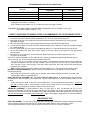
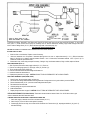
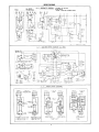
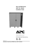
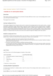
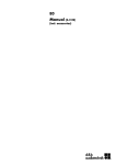
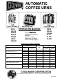
AUTOMATIC
COFFEE URNS
OPERATION MANUAL
FE75
FE100
FE200
FE250
FE300
INS75
INS100
Contents
Specifications
Unpacking and Inspection
Installation
Brewing Instructions
Maintenance Tips Repair
Parts List Wiring Diagrams
CRS3
CRS33
CRS66
CL75
CL100
CL200
ELECTRICAL SPECIFICATIONS
Kilowatts
Model No.
FE75, INS75, CRS3, CL75
FE100, INS100, CRS33
Amps
Volts
1 Phase
(3 wire)
3 Phase
(4 wire)
6
120/240
29
15
5.3
4.5
120/208
26
12
8
8
120/240
34
20
6
6
120/208
29
17
7
8
120/240
29
20
5.3
6
120/208
26
17
10
10
120/240
42
24
7.5
7.5
120/208
38
22
—
15
120/240
—
37
—
11.3
120/208
—
33
1 Phase
3 Phase
7
CL100
FE200, FE250, CRS66, CL200
FE300
CECILWARE CORPORATION
43-05 20th AVENUE, LONG ISLAND CITY, N.Y. 11105 • 718-932-1414 • FAX 718-932-7860
N059A-8/99
** UNPACKING AND INSPECTION **
UNPACKING INSTRUCTIONS: Carefully unpack urn and inspect immediately for shipping damage. Your automatic coffee urn was shipped in
a carton designed to give it maximum protection in normal handling. It was thoroughly inspected before leaving the factory and the carrier
accepted and signed for it. File any claims for shipping damage or irregularities directly with the carrier, not with the company.
ASSEMBLY ( SEE Illustration 3): The four legs (38), faucets (36), vent cap drain (2) and water strainer assembly (23,24) are packed separately
with urn. Install legs by tilting urn on its side and screwing legs into urn leg supports until hand tight. Carefully right unit and install in its
permanent location, being sure to leave at least 6" on right side of urn for access to controls. Level urn by adjusting legs. Then attach faucets
and install vent cap drain. Cover(s) (3) are shipped with knob(s) on inside to prevent damage. Simply unscrew and reverse knob(s) and
hardware. Your urn comes with one brew basket (11) and an introductory filter pack. Additional Cecilware filters are available from your dealer.
** INSTALLATION INSTRUCTIONS **
FOR QUALIFIED SERVICE PERSONS ONLY
CAUTION: DO NOT TURN THERMOSTAT ON UNTIL ALL INSTALLATION INSTRUCTIONS HAVE BEEN FOLLOWED.
WATER HOOK-UP (See Illustration 3): Your urn comes supplied with a water strainer assembly (23,24). Connect copper tubing (24) to elbow
(22) at lower back of side box; then connect other end of water strainer to a suitable length of 1 /4" tubing with shut-off valve (plumber
supplied), connected to cold water supply.
The National Sanitation Foundation also requires an approved flowback prevention device such as a double check valve to be installed
between urn and water supply. Adjust water pressure to 20 p.s.i. for proper operation.
STEAM URNS
Steam Inlet Pressure
Steam Requirement
Plumbing Connection
Electrical Connection
Input Power
SPECIFICATIONS
15-30 p.s.i.
7-21 Ibs./hr.
1/2n.p.t.
Plug line cord into any convenient 120V outlet
120 VAC, 6A, 50/60 HZ
TO PRIME: CAUTION: THERMOSTAT MUST BE IN THE "OFF position. Turn on water supply and electrical power to urn and wait until water
is visible in center gauge glass (left-hand gauge glass on 3-gallon single urns). Priming can be accelerated by manual filling through vent cap
opening in top of urn, using a water hose. Then turn thermostat knob (33, III. 3) to 10; thermostat pilot light shows heater is on. Urn jacket will
continue to fill automatically until water reaches the proper level. When indicator on dial thermometer (32) approaches the "W" in BREW zone,
197°-205°F (92°-96°C), urn is ready to brew coffee. In high altitude locations (at least 5000 ft. above sea level), thermostat may have to be
lowered to prevent boiling.
NOTE: FOLLOW THE ABOVE INSTRUCTIONS FOR INITIAL PRIMING AND AFTER DRAINING URN FOR SERVICING.
TO BREW COFFEE: Follow instructions on front of urn.
ELECTRIC URNS
All electric urns come wired single (1) or three (3) phase, except for the FE300 which is 3 phase only. See wiring diagrams,
Illustration 6.
1 Phase Hookup. Remove screws and lift off side box door. Terminal block (20, III. 3) is located on rear wall of side box. Install a
suitable conduit through knockout in rear of side box and connect No. 14 neutral wire to the center connection of terminal block
(20). Then connect the remaining 2 wires to terminals L1 and L2. 3 Phase Hookup. 3 phase units have a 4-wire terminal block.
Connect No. 14 neutral wire to end terminal marked NEUT and connect remaining wires to terminal L1, L2 and L3.
2
RECOMMENDED WIRE SIZE FOR FIELD-WIRING URNS
Wire Size
Model No.
Single Phase
Three Phase
FE75, CL75, CL100, CRS3, INS75
(2) 10 AWG
(3) 10 AWG
FE100, CRS33, INS100
FE200, FE250, CL200, CRS66
(2) 8AWG
(2) 6AWG
(3) 10 AWG
(3) 8AWG
FE300
—
(3) 8AWG
Neutral (N) and Ground Wires—14 AWG min.
NOTE: Field wiring must be suitable for 75° C. Use copper wire only for power supply connections.
GROUNDING: ON ALL URNS, CONNECT A GROUND WIRE TO GROUNDING LUG (19) TO COMPLY WITH LOCAL
ELECTRICAL CODES (14 AWG min. - 75°C)
** CORRECT PROCEDURES FOR BREWING COFFEE AS RECOMMENDED BY THE COFFEE BREWING CENTER **
1. Use fresh urn grind or drip grind coffee . . . spread evenly on filter for proper extraction.
2. Urn should be connected to cold water supply and water heated to 197°-205°F (92°-96°C) before brewing coffee.
3. While brewing, leave cover on urn to preserve aroma and prevent excessive steaming. Total contact time for urn grind should be
approximately 4-6 minutes.
4. Remove grounds and filter as soon as coffee has dripped through. Never pour coffee back through spent grounds.
5a. Urns with automatic agitator (FE and INS series) blend coffee automatically at end of brewing cycle. Press and hold agitator ON switch
(31) for additional blending.
b. If urn has a manual agitator (CL series), press and hold agitator ON switch (31) for 15 seconds after brewing cycle to blend coffee.
c. On urns without agitator (CRS series), blend coffee by drawing off about half of batch and pouring back into brew (after removing
grounds and filter).
6. Hold coffee at 185°-190°F (85°-88°C) (about 8 on thermostat). Brewed coffee should not be held for longer than one (1) hour
and should never be reheated.
SOLID-STATE TIMER ADJUSTMENT (ALL FE's, INS's and CRS's): A factory pre-set electronic solid-state timer controls the volume of
water for each brew cycle. If more or less water is desired, follow these instructions:
Turn knob of timer (18, III.3) clockwise to increase volume of water or counterclockwise to decrease it. Run through a complete brew
cycle after each adjustment. Since timer cannot be readjusted in mid-cycle, simply push cycle stop switch (25) at bottom right of side
box if water gets too high. If maximum setting of timer fails to deliver enough water, check water pump and spray head and follow
instructions under maintenance.
NDTE: The FE200 features a dual timer. The upper knob is factory-adjusted for a 11b. brew, the lower knob for the full 2 Ib. brew.
MECHANICAL TIMER ADJUSTMENT (ALL CL's): The factory pre-set mechanical timer can be adjusted for more or less water by
following these instructions:
Remove timer knob and loosen lock nut holding stop pin. To increase volume of water, rotate stop pin clockwise. To decrease, rotate
counterclockwise. Tighten lock nut and replace knob.
SPRAY ARM BY-PASS ADJUSTMENT (ALL FE's, INS's, CL2DD and CRS661 (See III. 2).: Adjustable bypass allows proper brew
extraction even with variations caused by soft or treated water. If bypass requires adjustment to correct for local water conditions, proceed
as follows:
Position spray head over center of coffee liner and press BREW switch. Turn by-pass adjustment screw clockwise to decrease bypass flow (for stronger coffee) or counter-clockwise to increase it (for less strong coffee). At end of brewing cycle, note volume of
water in coffee liner. Readjust timer if necessary to obtain the correct volume of water.
THERMOSTAT ADJUSTMENT: To adjust temperature of water in urn jacket (205°F or 96°C), turn thermostat knob (33, III. 3) to 10
(maximum clockwise position). Pull off knob and insert a small screwdriver into adjusting screw in center of shaft when temperature on dial
thermometer (32) approaches the "W" in the word BREW. Slowly rotate screw clockwise until thermostat pilot light goes out. Turning screw
clockwise lowers temperature and turning counter-clockwise raises it. Apply a sealer (glyptol or fingernail polish) to screw after adjustment
has been made.
** MAINTENANCE TIPS **
SPRAY ARM ASSEMBLY: The new improved spray head system was designed to facilitate easier cleaning and maintenance. The swivel
valve has a larger flow opening and the spray head cap is equipped with a stainless steel disc, used to control the flow of water.
When ordering replacement parts, be sure to order the correct disc and spray cap for each urn, as shown in Illustration 2.
3
To prevent lime buildup, especially in hard water areas, remove and clean spray head cap and spray head disc frequently. To clean swivel
valve (see III. 2) loosen nut and remove spray arm assembly from urn. Remove sediment by inserting a pipe cleaner through small hole in
valve. If maximum setting of timer (18. III. 3) fails to deliver enough water, check water pump (28).
FOR QUALIFIED SERVICE PERSONS ONLY
CAUTION: DISCONNECT POWER BEFORE ATTEMPTING ANY ELECTRICAL REPAIRS.
IF WATER FAILS TO HEAT:
1. Check line fuse or circuit breaker. Replace or reset if necessary.
2. Make sure thermostat is in ON position. If thermostat pilot light does not come on, replace thermostat (21, III. 3). (Refer to instructions
below.) If pilot light is on, measure continuity between terminals 1 and 2 of thermostat, and between terminals 3 and 4. (See III. 6) If a
resistance Is measured, replace thermostat.
3. If thermostat is okay, check wiring and repair if necessary; if wiring is okay, check heater resistance; if high or infinite, replace as follows:
REPLACING HEATER (See III. 3):
1.
2.
3.
4.
5.
6.
Shut off power and disconnect water supply at elbow (22,111.3). Drain urn.
Remove one coffee gauge glass (37), faucet (36), shank (37), and liner (12).
Tilt urn and disconnect wires to heater (34).
Remove socket head screw and heater flange and lift heater out.
Install new heater and reassemble urn.
Repeat priming instructions on page 2. CAUTION: DO NOT TURN ON THERMOSTAT UNTIL URN IS PRIMED.
REPLACING THERMOSTAT (FE200, FE250, FE300):
1.
2.
3.
4.
5.
6.
7.
Shut off power, disconnect water supply, and drain urn.
Tilt urn and check wiring underneath before removing thermostat. If wiring seems to be in good condition, proceed as follows:
Remove thermostat knob (33, III. 3) and two screws holding thermostat in place.
Disconnect wires from thermostat.
Unscrew packing nut and pull out thermostat bulb.
Install new thermostat.
Repeat priming instructions on page 2. CAUTION: DO NOT TURN ON THERMOSTAT UNTIL URN IS PRIMED.
REPLACING THERMOSTAT (All Other Models): Thermostat is located in side box instead of skirt of urn. Lift off side box door to gain
access to thermostat; then follow instructions above.
IF WATER FROM COLD WATER SUPPLY LINE DOES NOT ENTER URN:
1. Check water supply to external shut-off valve and water strainer (23, III. 3).
2. Check fuse (30) on front of side box and replace if necessary.
3. If water supply and fuse are okay, remove fuse and lift off side box door. Remove timer (18), exposing terminal block (16) (see III. 5)
and electrical wiring.
4
4.
Place wire jumper across terminals 8 and 9 of terminal block (III. 5). Reinstall fuse. If water enters urn, replace float switch (3), as
explained below. If no water enters urn, solenoid (27) or small relay (14) is not functioning. To check solenoid, remove fuse and
disconnect leads from coil; then reinstall fuse. If solenoid makes buzzing sound, replace relay. If no sound, replace solenoid.
REPLACING SOLENOID (27. III. 3):
1.
2.
3.
4.
Shut off water supply, remove fuse (30), and lift off side box door.
Disconnect wires from solenoid; then remove flare nut and unscrew solenoid valve from bracket.
Install new solenoid and reinstall fuse and side box door.
If necessary, follow priming instructions on page 2.
REPLACING FLOAT SWITCH (17, III. 3):
1.
2.
3.
4.
Remove fuse (30), lift off side box door, and remove timer (18) from bracket, exposing terminal block (16) and electrical wiring.
Disconnect float switch wires from terminals 8 and 9 on terminal block (see III. 5).
Unscrew packing nut from bottom of float can (13) and remove float switch (17) by pulling on wires.
Replace with new float switch and reassemble unit in reverse order.
CLEANING FLOAT CAN ASSEMBLY (13, III. 3): Periodically it may become necessary to clean float can (13, III. 3) to keep float switch (17)
operating properly.
1. Remove float can cover (10) and lift float (9) from stem.
2. Clean container and float, replace float on stem and reinstall cover.
IF WATER RUNS OUT AT OVERFLOW DRAIN (40. III. 3):
1. Make sure urn is level and overflow tube (45) is vertical.
2. Remove fuse (30) from front of side box. If water stops, replace float switch (instructions above).
3. If water continues to flow, solenoid valve is dirty or not seating properly. Replace solenoid as described above.
NO WATER FROM SPRAY HEAD (1, III. 3):
1. Check fuse (30) first.
2a. For all urns except CL's: Depress BREW switch (29) and release. If switch remains lit, water pump (28) is probably not operating. Lift
off side box door and check if fan on water pump is rotating. If not, replace pump as described below.
b. For CL urns: Turn brew timer knob clockwise. Replace timer if it does not go on. If timer goes on but pump doesn't, replace pump.
(See bottom left box of III. 5.)
REPLACING WATER PUMP (28. III. 3);
1.
2.
3.
4.
Shut off water supply and remove fuse (30). Drain urn to level of water faucet.
Lift off side box door and disconnect the two pump wires (see III. 5).
Loosen union fittings on pump and remove pump from urn.
Replace pump and follow priming instructions on page 2.
CHECKING SOLID-STATE TIMER (18. III. 3) (ALL URNS EXCEPT CL's): Press and hold BREW switch (29) for 10 seconds. Brew cycle should
start. If water stops coming from spray head as soon as BREW switch is released, timer is not operating. Replace it. (Instructions below.)
If no water comes from spray head when BREW switch is pressed, replace switch.
NOTE: To check mechanical timer on CL urns. refer to NO WATER FROM SPRAY HEAD, (see para. 2b above).
REPLACING SOLID-STATE TIMER (See III. 5):
1. Remove fuse (30, III. 3), lift off side box door. and remove timer from bracket.
2. Carefully note locations of colored wires on timer board, then remove wires.
3. Replace timer and reassemble unit in reverse order.
AGITATOR - AUTOMATIC TYPE (ALL FE AND INS URNS]:
OPERATION:
The agitator pump circuit is programmed to operate immediately after brewing cycle. The circuit pumps air through the coffee gauge
glass(es) into the coffee liner(s). The complete cycle takes about 20 seconds. For additional blending, simply press the agitator ON
switch (31, III. 3).
MAINTENANCE:
If agitation is not sufficient to blend coffee, check flexible tubing (6 and 44), and glasses and fittings, for possible air leaks. Replace
as necessary.
If agitator pump (5) does not operate immediately after brewing cycle or when agitator ON switch (31) is pressed, replace agitator
pump or solid state agitator timer (8).
If agitator pump comes on immediately after brewing cycle, but does not operate when agitator ON switch is pressed, replace
agitator ON switch.
5
AGITATOR • MANUAL TYPE (CL URNS)
OPERATION:
Immediately after brewing cycle, depress agitator ON switch and hold for about 20 seconds. Your coffee will be completely
blended and ready to serve.
MAINTENANCE:
If agitator pump does not operate when agitator ON switch is pressed, replace switch. If pump still does not operate,
replace pump.
ITEM NO.
1
1
1
1
2
2
3
3
3
4
4
5
6
7
7
7
8
9
10
11
11
11
11
12
12
12
12
12
13
14
15
16
17
18
18
18
18
18
19
19
20
20
21
22
23
24
25
25
26
27
27
27
27
27
27
27
27
28
28
28
28
28
29
30
30
31
31
32
32
33
34
33
34
34
34
34
34
STOCK NO.
E045A
E011A
E038A
E039A
U019A
E072A
Q024A
0011 A
Q092A
E023A
E036A
C511A
H050A
U152A
L249A
L251A
L238A
E040A
U022A
V002A
V003A
V081A
V113A
00820
Q094Q
0095Q
Q096Q
Q097Q
U023Q
L018A
C008A
B034A
L019A
L205A
L210A
L214A
L216A
L154A
B039A
C034A
BOOOA
B017A
L029A
K028A
E002A
H016Q
C396A
C142A
L017A
L022A
L010A
L080A
X008A
X033A
X035A
X036A
X038A
EOOOA
EOOOT
U070A
E069A
X032A
L012A
C395A
C141A
L236A
L052A
L007A
L323A
M008A
Q013A
G031A
G011A
G026A
G024A
G018A
G040A
REPAIR PARTS LIST
(See Illustration 3)
DESCRIPTION
Complete spray arm assm. w/bypass
Complete spray arm assembly
Complete spray arm assm. w/bypass
Complete spray arm assm. w/bypass
Vent cap drain
Vent cap drain
Cover with knob
Cover with knob
Cover with knob
3" Nipple union assembly
3" Nipple union assembly
Agitator pump assembly
9 ½” Agitator tubing
Agitator box cover
Agitator assm. (solid state aut.)
Agitator assembly (manual)
Solid state agitator timer
Float
Float can cover
Brew basket (s/s)
Brew basket (s/s0
Brew basket (s/s)
Brew basket (polypropylene)
Liner - 3 gallon
Left liner - 9 gallon
Right liner - 9 gallon
Left liner - 6 gallon
Right liner - 6 gallon
Float can assembly
Relay
Capacitor & resistor assm.
Terminal block
Float switch
Solid state timer 120V
Solid state timer 220V
Dual solid state timer 120V
Dual solid state timer 220V
Mechanical timer (Not shown)
Grounding lug
Contactor (Not shown)
Terminal block
Terminal block
Thermostat
Elbow
Water strainer
19" Copper tubing
Fuse holder, SC -6 type
Fuse holder, FN type (Canadian)
Cycle stop switch
Solenoid .28 GPM
Solenoid .50 GPM
Solenoid .75 GPM
Solenoid coil
Solenoid diaphragm repair kit
Solenoid flow washer (Not shown)
.28
Solenoid
flow washer (Not shown) .5
Solenoid flow washer (Not shown)
.75
G-water
pump
Rebuilt G-water pump
G-water pump fan
H-water pump
Seal kit for G-water pump
BREW switch
Fuse 6A SC -6
Fuse, 5AFN (Canadian)
Agitator
Agitator
Dial thermometer
Dial thermometer
Thermostat knob
Water heater 8kw-240V-1Ph
Water heater 7kw-240V-1Ph
Water heater 5kw-240V-1Ph
Water heater 8kw-240V-3Ph
Water heater 6kw-240V-3Ph
Water heater 5kw-240V-3Ph
Water heater 5kw-480V-3Ph
6
MODEL NO.
FE/INS/CL75, 100
CRS3, 33
FE/CL200: FE250: CRS66
FE300
All (except INS's)
All INS's
FE/INS/CL75, 100; CRS3. 33
FE/CL200: FE250: CRS66
FE300
All (except FE300)
FE300
All (except CRS's)
All (except CRS's)
All (except CRS's)
All FE's and INS's
All CL's
All (except CRS's)
All
All
FE/INS75, 100; CRS3, 33
FE/CL200; FE250: CRS66
FE300
CL75, 100
FE/INS/CL75, 100:CRS3, 33
FE300
FE300
FE/CL200; FE250; CRS66
FE/CL200; FE250; CRS66
All
All
All
All
All
All (except FE200 and CL's)
All (except FE200 and CL's)
FE200
FE200
All CL'S
All
FE300
All single phase
All three phase
All
All
All
All
All
All
All (except CL's)
FE/INS/CL75, 100; CRS3, 33
FE/CL200; FE250; CRS66
FE300
All
All
FE/INS/CL75, 100; CRS3, 33
FE/CL200; FE250; CRS66
FE300
All
All
All
All
All
All (except CL's)
All
All
All (except CRS's and CL's)
All CL's
Alt (except INS's)
All INS's
All
FE/INS100; CRS33
FE/INS/CL75; CRS3; CL100
FE/CL200; FE250; CRS66; FE300
FE/INS/CL100; CRS33
FE/INS/CL75; CRS3
FE/CL200; FE250; CRS66
FE/CL200; CRS66; FE250, 300
ITEM NO.
34
35
35
36
37
37
37
38
38
39
40
40
41
41
41
42
42
42
43
43
43
44
45
46
7
STOCK NO.
G043A
D021A
D045A
D017A
X005A
X004A
X044A
M005S
M172S
D022A
E009A
E071A
X006A
X030A
X043A
D024A
D001A
D032A
D001A
D020A
D031A
H051A
H0250
K108A
718
820
923
923
DESCRIPTION
Water heater 8kw -480V-3Ph
Shank for coffee gauge
Shank for gauges
Water and coffee faucet
Coffee gauge glass
Coffee gauge glass
Coffee gauge glass
Legs, chrome
Legs, black
Shank for water gauge
Overflow drain
Overflow drain
Water gauge glass
Water gauge glass
Water gauge glass
8" or 81/2" Water gauge shield
9" Water gauge shield
12" Water gauge shield
9" Coffee gauge shield
10-%" Coffee gauge shield
14%" Coffee gauge shield
5" Agitator Tubing
Overflow tube
Vent cap assembly
Filter pack (Not shown)
Filter pack (Not shown)
Filter Pack (Not Shown)
Filter pack (Not shown)
MODEL NO.
FE/INS/CL75, 100; CRS3, 33
All (except INS's)
All INS's
All
FE/INS/CL75, 100: CRS3, 33
FE/CL200; FE250; CRS66
FE300
All (except CL's)
All CL's
All (except INS's)
All (except INS's)
All INS's
FE/INS/CL75, 100; CRS3, 33
FE/CL200; FE250; CRS66
FE300
FE/INS/CL75, 100; CRS3, 33
FE7CL200; FE250; CRS66
FE300
FE/INS/CL75, 100; CRS3, 33
FE/CL200; FE250; CRS66
FE300
All (except CRS's)
All
All (except CRS's)
FE/INS/CL75, 100; CRS3, 33
FE/CL200; FE250; CRS66
FE300
FE300
8