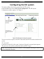
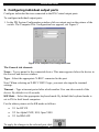
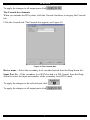
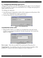
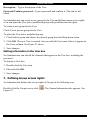
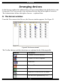
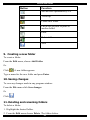
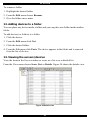
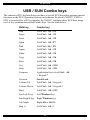
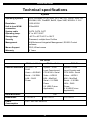
1
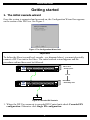
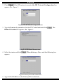
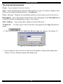
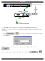
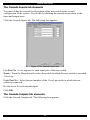
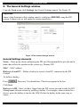
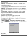
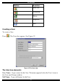
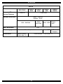
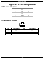
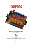
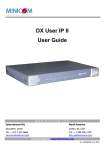
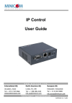
DX System
Operating Guide
Supported by:
®
Rackit ® Technology Corporation
274 Madison Avenue, New York, NY 10016
Tel: (212) 679-0050 • Fax: (212) 679-0040
Technology Corporation
International HQ
Jerusalem, Israel
Tel: + 972 2 535 9666
[email protected]
www.minicom.com
North American HQ
Linden, New Jersey
Tel: + 1 908 4862100
[email protected]
1 . 8 0 0 . 6 3 6 . 3 4 3 4
European HQ
Dübendorf, Switzerland
Tel: + 41 1 823 8000
[email protected]
Italy
Rome
Tel: + 39 06 8209 7902
[email protected]
Customer support - [email protected]
© Copyright Minicom Advanced Systems Ltd.
5UM20121 V1.3 9/04
w
DX SYSTEM
Table of Contents
Getting started .............................................................................. 2
1.
2.
The initial cascade wizard..................................................................... 2
Logging in .............................................................................................. 4
Configuring the DX system .......................................................... 5
3.
4.
Configuring individual output ports..................................................... 6
Configuring individual input ports ....................................................... 8
Cascading the DX system ............................................................ 9
5.
6.
Adding / editing secondary level KVM devices................................... 9
The General Settings window............................................................. 14
Creating Users and Groups ....................................................... 16
7.
Defining Group access rights............................................................. 18
Arranging devices ...................................................................... 21
8.
9.
10.
11.
12.
13.
The Servers window ............................................................................ 21
Creating a new folder .......................................................................... 22
Saving changes ................................................................................... 22
Deleting and renaming folders ........................................................... 22
Adding devices to a folder .................................................................. 23
Viewing the servers/devices ............................................................... 23
Operating the DX system ........................................................... 24
14.
15.
16.
17.
18.
Viewing devices ................................................................................... 24
Adjusting the picture quality .............................................................. 24
Power on/off reboot............................................................................. 24
Connect - Private ................................................................................. 25
Disconnect User .................................................................................. 25
Updating the DX Central............................................................. 26
19.
20.
21.
22.
23.
24.
25.
System requirements for the DX Central Update software .............. 26
Running the DX Central Update software.......................................... 26
Updating the DX User unit and X-RICCS ........................................... 27
Verifying the X-RICC version numbers.............................................. 28
Updating the firmware......................................................................... 29
Viewing the log .................................................................................... 29
Resetting the DX Central..................................................................... 30
USB / SUN Combo keys ............................................................. 31
Technical specifications ............................................................ 32
Appendix A: Pin assignments ................................................... 34
1
OPERATING GUIDE
Getting started
1. The initial cascade wizard
Once the system is connected and powered on, the Configuration Wizard box appears
on the screen of the DX User. See Figure 1.
Figure 1 The Configuration Wizard box
Important!
To define the Slave (second level cascade – see diagram below), you must physically
connect a DX User unit to the Slave. The initial cascade wizard appears and the
procedure outlined here must be followed.
www.minicom.com
I
0
POWER
100-250 VAC 50/60 Hz
5
6
7
8
17
18
19
20
21
22
23
24
25
26
27
28
29
30
31
32
1
2 USER 3
4
1
2
3
4
5
6
7
8
9
10
11
12
13
14
15
16
DX Central
- Primary level
SERVICE
SERVER
ETHERNET
SERIAL
Cascade
www.minicom.com
I
0
POWER
100-250 VAC 50/60 Hz
5
6
7
8
17
18
19
20
21
22
23
24
25
26
27
28
29
30
31
32
1
2 USER 3
4
1
2
3
4
5
6
7
8
9
10
11
12
13
14
15
16
DX Central
- Secondary level
SERVICE
SERVER
ETHERNET
SERIAL
Server
Figure 2 Cascaded DX Centrals
1. Where the DX User connects to cascaded DX Central units check Cascaded DX
configuration. Otherwise click Single DX configuration.
2
DX SYSTEM
2. Click
. If the DX system is cascaded the DX Network Configuration box
appears. See Figure 3.
Figure 3 The DX Network Configuration box
3. Type in the network parameters for this DX Central unit and click
Define DX status box appears. See Figure 4.
. The
Figure 4 The Define DX status box
4. Select the status and click
appears.
. When defining a Slave unit the following box
Figure 5 Primary DX unit IP address box
5. Type in the IP address of the Primary DX Central unit.
3
OPERATING GUIDE
6. Click
. The Login screen appears see below.
2. Logging in
Once the system is connected and powered on, the Login screen appears on the monitor
of each DX User. See Figure 6.
Figure 6 The Login screen
Type the default username ‘admin’ and password ‘admin’. The Main screen appears.
See Figure 7. The screen initially shows no devices. The system must be configured.
Toolbar icons
Created folders
appear here
Devices
appear
here
Figure 7 The Main screen
4
DX SYSTEM
Configuring the DX system
You must configure the devices connected to the DX system.
From the View menu choose DX System Configuration. The DX System
Configuration window appears. See Figure 8.
Input ports from DX Users
Output ports to devices
List of DX Central
units and KVM
switches
Information of
currently selected
unit
Figure 8 The DX System Configuration window
You can view the rear ports of the DX Central units and KVM switches attached to the
system.
To view a unit:
From the list on the left, click a unit. A picture of the unit’s rear panel ports appears.
The ports are color coded as outlined by the list of RICC Types.
Note! Place the mouse cursor over a button. A tool tip appears showing the name of the
device connected to that port.
5
OPERATING GUIDE
3. Configuring individual output ports
Configure individual devices connected to the DX Central output ports.
To configure individual output ports:
1. In the DX System Configuration window click an output port on the picture of the
switch. The Computer Port Configuration box appears, see Figure 9.
Figure 9 The Computer Port Configuration box
The General tab elements
Name – Type a name for the connected device. This name appears below the device in
the Servers and devices window.
Type – Select the appropriate X-RICC connected to the port.
Note! When selecting an X-RICC RS232 type, you must also input the terminal
settings.
Timeout – Type a timeout period after which another User can take control of the
device. By default it is 60 seconds.
KB Mode – Select the appropriate keyboard mode. By default the keyboard mode is
set to PS for Intel based computers.
For the other systems set the KB mode as follows:
•
U1 for HP UX
•
U2 for Alpha UNIX, SGI, Open VMS
•
U3 for IBM AIX
To apply the changes to the selected port click
6
.
DX SYSTEM
To apply the changes to all output ports click
.
The Cascade box elements
When you cascade the DX system, click the Cascade checkbox to un-gray the Cascade
tab.
Click the Cascade tab. The Cascade box appears see Figure 10.
Figure 10 The Cascade box
Device name – Select the secondary level cascaded switch from the Drop-down list.
Input Port No – If the secondary level KVM switch is a DX Central, from the Dropdown list select the input port number of the secondary level DX Central.
To apply the changes to the selected port click
To apply the changes to all output ports click
7
.
.
OPERATING GUIDE
4. Configuring individual input ports
Although the input ports in the DX Management console appear to be un-configured,
the DX system does recognize the connected DX Users. Configure the input ports to
display the DX User icon.
To configure the input ports:
1. In the DX System Configuration window click an input port on the picture of the
switch. The Configuration box appears see Figure 11.
2. From the Drop-down box choose the DX User unit.
Figure 11 The Configuration box
Cascaded DX Central units
3. When the DX Central is a secondary level cascaded unit, click the Cascade
checkbox to un-gray the Cascade tab. Click the Cascade tab. The Cascade box
appears see Figure 12,
Figure 12 Cascade box
Device name – Select the cascaded KVM switch from the Drop-down list.
Output Port No - From the Drop-down list select the output port number of the
primary DX Central to which the secondary level unit is connected.
8
DX SYSTEM
Cascading the DX system
When cascading DX Central units or other KVM switches, you must configure them in
the DX System Configuration window – see Figure 8. Where the switch is not
cascaded you can ignore this section and go to page 14.
5. Adding / editing secondary level KVM devices
The table below explains the DX Management console Toolbar buttons.
Button
Function
Add unit
Delete unit
Edit unit
To add a new KVM switch:
Click
. The Add New KVM Device box appears. See Figure 13.
Figure 13 The Add New KVM Device box
9
OPERATING GUIDE
The General tab elements
Name – Type a name for the new device.
Type – From the Drop-down list select the new device type. If it doesn’t appear in the
list, it can be added (explained below - To add new…).
Users / Servers – Displays the maximum number of users and servers for the device
Description – type a description of the device. This will appear in the Description box
in the DX System Configuration window. See Figure 8.
MAC Address – Type in the MAC address of the KVM device.
To add new…- To add a type of device that does not appear in the Type Drop-down
menu:
1. Click
. The Add New Device Type box appears. See Figure 14.
Figure 14 The Add New Device Type box
2. Type a name for the new device and select the number of input and output ports.
Figure 15 below illustrates input and output ports.
10
DX SYSTEM
www.minicom.com
I
0
POWER
100-250 VAC 50/60 Hz
5
6
7
8
17
18
19
20
21
22
23
24
25
26
27
28
29
30
31
32
1
2 USER 3
4
1
2
3
4
5
6
7
8
9
10
11
12
13
14
15
16
DX Central - Primary level
SERVICE
SERVER
ETHERNET
SERIAL
Cascade
Input port
X-RICC
New KVM switch Secondary level
Output port
Connects to
server - 1 level
down
To Server
Figure 15 Input and output ports
3. Click OK. The new device type is added to the Type Drop-down menu.
To edit…_ To remove a device or change the number of input and output ports for a
device type:
1. Click
See Figure 16.
or
. The currently selected device Properties box opens.
Figure 16 The Properties box
2. Choose the number of input and output ports (see Figure 15) and click
.
To remove the device type from the Drop –down list, click
11
or
.
OPERATING GUIDE
The Cascade Inputs tab elements
You must define the cascade level position of the new switch in the overall
configuration of the system. You do this by defining the cascade connections to the
input and output ports.
Click the Cascade Inputs tab. The following box appears.
Figure 17 The Cascade Inputs box
Left Port No. A row appears for each input port of the new switch.
Name – From the Drop-down list select the switch to which the new switch is cascaded
1 level up.
Right Port No – Select the port number of the 1 level up switch to which the new
switch is connected.
Do the above for each cascaded port.
Click OK.
The Cascade Outputs tab elements
Click the Cascade Outputs tab. The following box appears.
12
DX SYSTEM
Figure 18 The Cascade Outputs box
Left Port No. A row appears for each output port of the new switch.
Name - From the Drop-down list select the device to which the new switch is
connected 1 level down.
Right Port No – Select the port number of the 1 level down device to which the new
switch is connected.
Do the above for each cascaded port.
Click OK.
Note! Once you have manually input the cascaded ports at one level you do not have to
repeat the process at the levels above or below.
Configuring individual output and input ports
Configure the individual output and input ports of cascaded units as explained in
sections 3 and 4 on pages 6 and 8 above.
Note! When configuring the output ports of a non-DX switch you must define the
hotkey to access the device. See the switch’s User guide for the correct hotkey.
To input the hotkey:
1. Click
. The HotKey box opens.
2. Press the hotkey keys on your physical keyboard. The keys appear in the HotKey
box.
3. Click Assign. The hotkey is assigned.
13
OPERATING GUIDE
6. The General Settings window
From the Tools menu click Settings, the General Settings appear. See Figure 19.
Important!
Some of the elements in this window must be configured BEFORE using the DX
system. Failure to do so will make the system inoperative.
Figure 19 The General Settings window
General Settings elements
Name – Name given when configuring the DX unit. Recommended to give the unit a
name that reflects its position in the system e.g. Primary DX.
MAC – MAC address
Hotkey to Local PC – Define a hotkey to access a local PC connected to the DX
Central.
To define a hotkey:
Press
. Press any 2 keyboard-keys. These keys appear in the box.
Click Save.
Hotkey to AIM – Once you have logged into the DX system you can invoke the DX
Management software screen by pressing a hotkey. For example, when switched to a
device, press the hotkey to invoke the AIM. Define the hotkey in the same way as
above.
14
DX SYSTEM
Security elements
Security Off – When checked, there is no login screen. ALL Users have access to
control and power devices.
To again display the login screen:
From the File menu choose Log off. The Login screen appears and the Administrator
can enter his password.
Security On – When checked security access levels are as set by the Administrator
Security High – When checked Users must login every time they exit and re-enter the
AIM.
Lock configuration – When checked, the system will only recognize the current
devices configured. Any changes in the devices physically connected will not be
recognized by the system.
IP/Cascade Settings elements
IP Address – Type a Static IP address in the usual dot notation.
Subnet mask – Type the net mask of the local network.
Default Gateway – Type a Default Gateway address. Where the DX system is
accessible from networks other than the local one, this IP address must be set to the
local network router's IP address.
Configure cascade options – When you want to change cascade status of the DX
system click
change.
. The Cascade configuration box appears. Make the desired
Figure 20 Cascade configuration box
Time Settings
Set the time and date.
15
OPERATING GUIDE
Creating Users and Groups
From the View menu choose Users and Groups.
The Users and Groups window appears. See Figure 21.
Figure 21 Users and Groups window
By default there are 3 Groups in the Groups column. Each Group has specific access
rights that cannot be altered.
The 3 default groups are:
Group
Access rights
Administrators
Full access and power management of all computers.
Plus all DX Functions:
Adding and removing devices
Creating Users and Groups.
Setting time date and IP address.
Power Users
Full access and power management of all computers
Users
Full access to all computers
An Administrator can create new Groups with different access rights.
When a Group is highlighted all the Users in the group appear in the Users column. In
the Administrators Group there is 1 default Administrator (admin).
The table below explains the functions of the Toolbar buttons.
16
DX SYSTEM
Button
Function
Add User
Add group
Delete
Properties
Save
Creating a User
To create a User:
Press
. The Users box appears. See Figure 22.
Figure 22 The Users box
The User box elements
User Name – Type a name for the User. This name appears below the User’s icon in
the Users and Groups window.
Full Name - Type a full name for the User.
17
OPERATING GUIDE
Description – Type a description of the User.
Password/Confirm password – Type a password and confirm it. This can be left
blank.
An Administrator can create a new group for the User and define unique access rights
or he can place the User into a predefined group with predefined access rights.
To create a new group for the User:
Check Create private group for the User.
To place the User into a predefined group:
1. Check Select group and choose the desired group from the Drop-down menu.
2. Click OK. The new User is created. An icon with the User name below it appears in
the Users column. See Figure 21 above.
3. Save changes.
Editing information in the User box
An Administrator can edit all the elements that appear in the User box, including the
password.
To display a User box:
1. Double-click the User icon.
2. Edit and click OK.
3. Save changes.
7. Defining Group access rights
An Administrator defines the access rights of Groups in the following way.
Double-click the Group icon or click
Figure 23.
. The General information box appears. See
18
DX SYSTEM
Figure 23 The General information box
The General information box elements
Group name – Edit the Group name here
Timeout – After a period of non-activity the system automatically logs out. Type a
timeout period in seconds in this box. Once Timeout activates click anywhere on the
screen to display the Login box.
By default the Timeout value is 60 meaning there is a Timeout period of 1 minute.
Private connection – When checked, it gives the User the option to prevent other
Users from viewing computers accessed by members of this group.
Description – type a description of the group
The Access box
Click the Access tab, the Access box appears. See Figure 24
List of
devices
Figure 24 The Access box
Here the Administrator defines the access rights for each connected device.
19
OPERATING GUIDE
The Access box elements
Denied – By default access is denied to all devices.
View – Check to allow viewing access only.
Control - Check to allow controlling (and viewing) of the device.
Power - Check to allow powering the device on and off (as well as controlling and
viewing of the device).
1. Go through each device defining the access rights.
2. Click OK.
3. Save changes.
Defining the same access rights for all devices
To give every device the same access right, click the desired option button at the top of
the column. E.g. to give the group, viewing access to every device, click
and confirm.
20
DX SYSTEM
Arranging devices
In the Servers window the Administrator or User creates folders into which devices can
be inserted. The User can only view and insert devices that he has rights of access to.
The Administrator defines the rights of access – explained later.
8. The Servers window
From the View menu select Servers, the Servers window appears. See Figure 25.
Figure 25 The Servers window
The Toolbar buttons and their functions are explained in the following table.
Button
Function
Connect to server/devices
Connect to local computer
Power on
Power off
Reboot
Search for folder/device by name
Sort devices alphabetically A-Z
21
OPERATING GUIDE
Button
Function
Sort devices alphabetically Z-A
1 level up
Create new folder
Cut device to paste to paste to
another folder
Paste
Delete folder
Save
9. Creating a new folder
To create a folder:
From the Edit menu, choose Add Folder
Or.
Click
. A new folder appears.
Type a name for the new folder and press Enter.
10. Saving changes
To save any changes made in any program window:
From the File menu click Save changes.
Or
Click
.
11. Deleting and renaming folders
To delete a folder:
1. Highlight the desired folder.
2. From the Edit menu choose Delete. The folder deletes.
22
DX SYSTEM
To rename a folder:
1. Highlight the desired folder.
2. From the Edit menu choose Rename.
3. Give the folder a new name.
12. Adding devices to a folder
You can place any device inside a folder and you can place one folder inside another
folder.
To add devices (or folders) to a folder:
1. Click the device.
2. From the Edit menu click Cut.
3. Click the desired folder.
4. From the Edit menu click Paste. The device appears in the folder and is removed
from the list of devices.
13. Viewing the servers/devices
View the items in the Server window as icons, as a list or as a detailed list.
From the View menu choose Icons, List or Details. Figure 26 shows the details view.
Figure 26 Details view
23
OPERATING GUIDE
Operating the DX system
14. Viewing devices
To view a device:
From the Servers window double-click a device. Or select the device and click
The devices screen appears.
To return to the DX window:
Press right Ctrl, F12. This hotkey can be changed in the Tools/Options window.
15. Adjusting the picture quality
You can adjust the picture quality of each computer.
To do so:
1. In Servers window, click once on the desired computer’s icon.
2. From the Action menu select Video Tuning. The selected computer’s screen
appears.
3. Use the keyboard Up, Down and Left, Right Arrow keys to adjust the picture.
4. When the picture is satisfactory, press Esc. The Servers window reappears.
5. Save the changes.
16. Power on/off reboot
These power options are available to Administrators and to Users with Power
management rights.
To perform these functions:
1. Select the desired device.
2. Select the desired function from the Toolbar buttons or the Action menu.
24
.
DX SYSTEM
17. Connect - Private
This option appears in the Action menu and is available to Administrators and to Users
with private connection rights. See page 19.
To activate Connect - Private:
1. Select the desired device.
2. From the Action menu select Connect - Private. Other Users are prevented from
viewing the selected computer.
18. Disconnect User
The Administrator can remove a User from any device.
To remove a User:
1. Select the desired device.
2. From the Action menu select Disconnect User. The User is removed from the
device.
25
OPERATING GUIDE
Updating the DX Central
The Update Utility program is located on the Minicom Flash USB key.
19. System requirements for the DX Central Update software
•
Pentium 166 or higher with 16 MB RAM and 10 MB free Hard Drive space.
•
Free Serial port.
•
Windows 98 and later.
20. Running the DX Central Update software
1. Install the program on any Windows-based computer connected to the DX network.
A shortcut icon appears on the desktop
.
2. Double-click the icon. The Update Utility program appears.
3. Click Next. The IP address box appears. See Figure 27.
Figure 27 The IP address box
4. You must input the IP address of the DX Central unit. The default IP address is
shown, if the IP address is different, type in the new IP address and click Next. The
Update Options screen appears.
Figure 28 The Update Options screen
26
DX SYSTEM
5. Choose one of the following:
•
Upgrade the Central unit’s firmware
•
Backup the database
•
Load a saved database
•
Restore factory defaults – thereby erasing the data base
To do any of the above, check the desired option and click Next.
6. To upgrade the firmware or load a database, locate the file and click Open.
To backup the database, save the current database to the Hard drive.
To restore factory defaults, press OK.
21. Updating the DX User unit and X-RICCS
With the DX system you can update the firmware for the:
•
DX User unit
•
X-RICCs – PS2, RS232, SUN and USB
DX Update enables you to add new features and fix bugs in a quick and efficient
manner.
To update the firmware the DX system must be connected and switched on.
To obtain the latest firmware for your system go to www.minicom.com .
1. Download the latest firmware to the Minicom Flash USB key.
2. Insert the key into the USB port of a DX User. The firmware file appears in the
Files in USB column.
3. From the DX program, choose Tools/Update. The Update window appears, see
Figure 29.
27
OPERATING GUIDE
Figure 29 The Update window
4. In the DX System box select the desired component to update. The device name,
version and date appear. In the Files in USB column the update firmware appears.
The table below explains the functions of the buttons and boxes in the DX Switch
Update window.
Button or Box
Function
Starts firmware download
Selects all X-RICCs
Unselects selected X-RICCs
Displays the firmware version number
Displays the hardware version number
Press to display general information
about the firmware file on the USB
key
22. Verifying the X-RICC version numbers
Before upgrading the firmware, you can verify which firmware and hardware versions
the X-RICCs currently have.
To verify the X-RICC version number:
1.
In the DX System box click the Checkbox of the desired X-RICC type.
28
DX SYSTEM
2.
Click
number.
. The firmware version number appears after the X-RICC
3.
Click
RICC number.
. The hardware version number appears after the X-
When “Not responding” appears, there is no computer connected, or it is switched off.
23. Updating the firmware
Warning!
Never switch off any computer connected to the system during the updating process.
To update the firmware:
1.
In the DX Switch Update window, check the appropriate option - the DX User or
the desired X-RICC .
2.
. The DX Switch Update flashes the firmware. On
Click
completion the firmware version number appears.
3.
Check that the updated version number is correct by pressing
.
Firmware Update generates one log file per session that displays a chronological list of
actions. You can read the log file in any ASCII text editor. The log file is located in the
Windows directory.
24. Viewing the log
View a log of all the activities that have occurred during the latest session. See the
exact time, source, User and the event that occurred.
To view the log:
From the View menu, click Log. The Log window appears see Figure 30.
29
OPERATING GUIDE
Figure 30 The Log window
25. Resetting the DX Central
To reset the DX Central, press the Reset button on the rear panel. The X-RICCs are
unaffected by this reset.
30
DX SYSTEM
USB / SUN Combo keys
The connected PS/2 keyboard does not have a special SUN keypad to perform special
functions in the SUN Operating System environment. So when a X-RICC USB or
SUN is connected to a SUN computer, the X-RICC emulates these SUN keys using
a set of key combinations called Combo keys. See the table below.
SUN key
Combo key
Stop
Left Ctrl + Alt + F1
Props
Left Ctrl + Alt + F3
Front
Left Ctrl + Alt + F5
Open
Left Ctrl + Alt +F7
Find
Left Ctrl +Alt + F9
Again
Left Ctrl + Alt + F2
Undo
Left Ctrl + Alt + F4
Copy
Left Ctrl + Alt + F6
Paste
Left Ctrl + Alt + F8
Cut
Left Ctrl + Alt + F10
Help
Left Ctrl + Alt + F11
Compose
Application key or Left Ctrl + Alt
+ Keypad *
Crescent
Scroll Lock
Volume Up
Left Ctrl + Alt + Keypad –
Volume Down
Left Ctrl + Alt + Keypad +
Mute
Left Ctrl + Alt + F12
Sun Left ◊ key
Left Windows key
Sun Right ◊ key
Right Windows key
Alt-Graph
Right Alt or Alt Gr
Stop A
Left Ctrl + Alt +1
31
OPERATING GUIDE
Technical specifications
System
Operating systems
DOS, Windows (3x, 9x, 2000, NT4, ME, XP), LINUX, UNIX, HP
UX QNX, SGI, FreeBSD, BeOS, Open VMS, NOVELL 3.12-6
Resolution
1600 X1200
Unit to local KVM
connection
200m/660ft
System cable
CAT5, CAT6, CAT7
Operating temp.
0° to 40°C/104°F
Storage temp.
-40°C to 40°C/-40°F to 104°F
Security
Password, multiple User Profiles
Management
AIM Advanced Integrated Management, RS-232 Control
software
Mouse Support
PS/2, Wheel mouse
Warranty
3 Years
DX units
DX Central Unit
Cables/Connectors
Out Port – 32
RJ45
Users – 4/8 RJ45
Serial – 2 X DB9
LAN – RJ45
Power
DX User Unit
System – RJ45
Local Console and
CPU KVM + Serial
Video – HDD15
K/M – MiniDin6
Serial – 2 X DB9
Power
2 X USB (Future
Application)
Rack Mountable
DXU IP
System – RJ45
Local Console and
CPU KVM + Serial
Video – HDD15
K/M – MiniDin6
Serial – 2 X DB9
LAN – RJ45
Power
2 X USB (Future
Application)
Yes
Dimensions
17X11X1.6”
Power
Consumption
100 – 250 VAC 50/60 Hz
8.5X11X1.6”
32
17X11X1.6”
DX SYSTEM
RICCS
RICC PS/2
Server to DX
Central Distance
X-RICC
PS/2
X-RICC
SUN
10m/33ft
Video – HDD15
System - RJ45
K/M –
MiniDin8
K/M - MiniDin6
Rack Mountable
Dimensions
X-RICC
RS232
100m/330ft
Cables/Connectors
Power supply
X-RICC
USB
K/M - USB
Power Jack
Yes
From Keyboard
24x91x41mm /
0.94x3.58x1.61”
From USB
Power
Adapter
26x91x45mm / 1.05x3.58x1.77”
33
OPERATING GUIDE
Appendix A: Pin assignments
RS232 Serial cable pin-out
RJ11 Service
1
2
3
4
5
6
Signal
N/C
TXD
RXD
N/C
GND
N/C
DB9
2
3
5
-
RJ 45 Connector Ethernet
8
1
Pin
Assignment
Pin
Assignment
1
2
3
4
TX +
TX RX +
Not connected
5
6
7
8
Not connected
RX Not connected
Not connected
34
DX SYSTEM
35