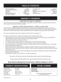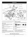
1
Operator's
Manual
CRRFr MRN
30" SNOW THROWER
Model No. 247.883960
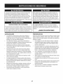
,, SAFETY
o ASSEMBLY
OPERATION
MAINTENANCE
PARTS LIST
o ESPANOL
CAUTION" Before using this
product, read this manual and
follow all safety rules and operating
instructions.
Sears Brands
Management
Corporation,
Visit our website:
Hoffman
www.craftsman.com
Estates,
IL 60179, U.S.A.
FormNo. 769-08184B
(July 18,2012)
Warranty
Statement....................
SafeOperationPractices..............
Assembly.........................
Operation........................
Service&Maintenance
..............
Off-Season
Storage...................
Page2
Pages3-6
Pages8-12
Pages13-17
Pages18-23
Page24
Troubleshooting
......................
Page25
PartsList.........................
Pages26-41
RepairProtection
Agreement
............
Page45
Espadol
.............................
Page46
ServiceNumbers...................
BackPage
CRAFTSMAN
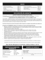
TWOYEARFULLWARRANTY
FOR
TWOYEARS
fromthedateofpurchase,
thisproduct
iswarranted
against
anydefects
inmaterial
orworkmanship.
Defective
product
will
receive
freerepair
orfreereplacement
ifrepair
isunavailable.
ADDiTiONAL LiFETiME LiMiTED WARRANTY on UPPER and LOWER CHUTE
FORAS LONGAS IT IS USEDbythe originalownerafter the secondyear fromthe dateof purchase,theupperand lowerchuteof this snow
throwerare warrantedagainstany defectsin materialor workmanshipas verifiedby a Searsauthorizedserviceprovider.With proofof purchase,
youwill receivea newchutefree of charge.Youare responsiblefor the laborcost of installationand any costincurredto verify thedefect.
Forwarrantycoveragedetailsto obtainrepairor replacement,visitthe web site:www.craftsman.com
This warrantycoversONLYdefectsin materialand workmanship.Warrantycoveragedoes NOTinclude:
•
Expendableitemsthat can wearoutfrom normalusewithin thewarrantyperiod,includingbut not limitedto augers,auger paddles,drift
cutters,skid shoes,shaveplate, shearpins, spark plug,air cleaner,belts,and oil filter.
•
Standardmaintenanceservicing,oil changes,or tune-ups.
Tire replacementor repaircausedby puncturesfrom outsideobjects,such as nails,thorns,stumps,or glass.
•
Tireor wheelreplacementor repairresultingfrom normalwear,accident,or improperoperationor maintenance.
Repairsnecessarybecauseof operatorabuse, includingbutnot limitedto damagecausedby over-speedingthe engine,or from impacting
objectsthat bendthe frame,auger shaft,etc.
Repairsnecessarybecauseof operatornegligence,includingbut not limitedto, electricaland mechanicaldamagecausedby improper
storage,failureto usethe propergradeand amountof engineoil, or failureto maintainthe equipmentaccordingto the instructionscontained
in the operator'smanual.
•
•
Engine(fuelsystem)cleaningor repairscausedbyfuel determinedto be contaminatedor oxidized(stale).in general,fuel shouldbe used
within30 daysof its purchasedate.
Normaldeteriorationand wearof the exteriorfinishes,or productlabel replacement.
This warrantyis void if this productis ever usedwhileprovidingcommercialservicesor if rentedto anotherperson.
This warrantygivesyou specificlegal rights,and you mayalso haveotherrightswhich vary from stateto state.
Sears Brands
Management
EngineOil Type:
EngineOil Capacity:
SAE5W-30
37 ounces
FuelCapacity:
SparkPlug:
Approx.5 Quarts
F6RTC(951-10292)
SparkPlug Gap:
.020"to .030"
Corporation,
Hoffman
Estates,
IL 60179
Model Number.................................................................
Serial Number .................................................................
Dateof Purchase.............................................................
Recordthe modelnumber,serialnumber
and dateof purchaseabove
© Sears Brands,LLC
2
This machinewas builtto be operatedaccordingto the safeoperation practicesin this manual.As with anytype of powerequipment,
carelessnessor error on the partof the operatorcan resultin serious
injury.This machineis capableof amputatingfingers,hands,toes
and feet and throwingdebris.Failureto observethe followingsafety
instructionscouldresultin seriousinjuryor death.
This symbolpointsout importantsafetyinstructionswhich,if not
followed,couldendangerthepersonalsafetyand/orpropertyof
yourselfand others. Readand followall instructionsin this manual
beforeattemptingto operatethis machine.Failureto complywith
these instructionsmay resultin personalinjury.Whenyou seethis
symbol,HEEDITS WARNING!
CALIFORNIA
PROPOSITION
65
Your Responsibility--Restrict the use of this powermachineto
personswho read,understandand follow thewarningsand instructions in this manualand on the machine,
EngineExhaust,someof its constituents,and certainvehicle
componentscontainor emit chemicalsknownto Stateof California
to cause cancerand birthdefects or otherreproductiveharm,
SAVE THESE INSTRUCTIONS!
TRAiNiNG
PREPARATION
•
Thoroughlyinspectthearea wherethe equipmentisto be used.
Removeall doormats,newspapers,sleds,boards,wires and other
foreignobjects,whichcouldbe trippedoveror thrownby the auger/
impeller.
•
Alwayswear safetyglassesor eyeshieldsduringoperationand
while performingan adjustmentor repairto protectyoureyes.
Thrownobjectswhich ricochetcancause seriousinjuryto the
eyes.
Donot operatewithoutwearingadequatewinteroutergarments.
Donot wearjewelry,long scarvesor otherlooseclothing,which
could becomeentangledin movingparts.Wearfootwearwhich
will improvefooting on slipperysurfaces.
Usea groundedthree-wireextensioncordand receptaclefor all
machineswith electricstartengines.
•
•
Read,understand,and followall instructions
on the machineand
in themanual(s)beforeattemptingto assembleand operate.
Failureto do socan resultin serious injuryto the operatorand/
or bystanders.Keepthis manualin a safe placeforfuture and
regularreferenceand for orderingreplacementparts.
Be familiarwith all controlsand their properoperation.Knowhow
to stop the machineand disengagethemquickly.
Neverallowchildrenunder 14 yearsof age to operatethis
machine.Children14and over shouldreadand understandthe
instructionsand safe operationpracticesin this manualand on
the machineand be trainedand supervisedby an adult.
Neverallowadultsto operatethis machinewithoutproper
instruction.
•
•
Thrownobjectscan causeseriouspersonalinjury. Planyour
snow-throwingpatternto avoiddischargeof materialtoward
roads,bystandersand the like.
Keepbystanders,pets and childrenat least75 feet from the
machinewhile it is in operation.Stopmachineif anyoneenters
the area.
Disengageall controlleversbeforestartingthe engine.
Adjust collectorhousingheightto cleargravelor crushedrock
surfaces.
•
Exercisecautionto avoidslippingor falling,especiallywhen
operatingin reverse.
3
Neverattemptto make anyadjustmentswhileengineis running,
exceptwherespecificallyrecommendedin the operator'smanual.
Letengineand machineadjustto outdoortemperaturebefore
startingto clearsnow.
Safe Handling of Gasoline
Toavoidpersonalinjuryor propertydamageuseextremecare in
handlinggasoline.Gasolineis extremelyflammableand the vaporsare
explosive.Seriouspersonalinjurycan occurwhengasolineis spilled
on yourselfor yourclotheswhichcan ignite. Washyour skin and
changeclothesimmediately.
•
•
•
Neverremovegas capor add fuel whilethe engineis hot or
running.
•
•
Allowengineto coolat leasttwo minutesbeforerefueling.
Neveroverfill fueltank. Fill tankto no morethan1/2inchbelow
bottomof filler neck to providespace forfuel expansion.
Replacegasolinecapand tighten securely.
Exerciseextremecautionwhenoperatingon or crossinggravel
surfaces.Stay alertfor hidden hazardsor traffic.
Exercisecautionwhenchangingdirectionand whileoperatingon
slopes.Do notoperateon steep slopes.
Planyoursnow-throwingpatternto avoiddischargetowards
windows,walls,cars etc. Thus,avoidingpossibleproperty
damageor personalinjurycausedby a ricochet.
Neverdirect dischargeat children,bystandersand petsor allow
anyonein front of the machine.
Use onlyan approvedgasolinecontainer.
Extinguishall cigarettes,cigars,pipesand other sourcesof
ignition.
Neverfuel machineindoors.
•
•
•
Donot overloadmachinecapacityby attemptingto clearsnowat
too fastof a rate.
Neveroperatethis machinewithoutgoodvisibility or light. Always
be sureof yourfootingand keepa firm hold on the handles.Walk,
neverrun.
Disengagepowerto theauger/impellerwhentransportingor not
in use.
If gasolineis spilled,wipe it off theengineand equipment.Move
machineto anotherarea.Wait5 minutesbeforestartingthe
engine.
Neverstorethe machineor fuel containerinsidewherethereis an
openflame,spark or pilotlight(e.g. furnace,waterheater,space
heater,clothesdryeretc.).
Neveroperatemachineat high transportspeedson slippery
surfaces.Lookdownand behindand usecare whenbackingup.
If the machineshouldstart to vibrateabnormally,stop the engine,
disconnectthe spark plugwire and groundit againstthe engine.
Inspectthoroughlyfor damage.Repairanydamagebefore
startingand operating.
•
•
Allowmachineto cool at least 5 minutesbeforestoring.
Neverfill containersinsidea vehicleor on a truckor trailerbed
with a plasticliner.Alwaysplacecontainerson the groundaway
fromyour vehiclebeforefilling.
•
If possible,removegas-poweredequipmentfrom the truckor
trailerand refuelit on the ground.If this is not possible,then refuel
such equipmenton a trailerwith a portablecontainer,ratherthan
froma gasolinedispensernozzle.
Keepthe nozzlein contactwith the rimof the fuel tank or
containeropeningat all times untilfuelingis complete.Do not use
a nozzlelock-opendevice.
Disengageall controlleversand stop enginebeforeyouleave
the operatingposition(behindthe handles).Wait untilthe auger/
impellercomesto a completestop beforeuncloggingthechute
assembly,makingany adjustments,or inspections.
Neverput yourhand in the dischargeor collectoropenings.Do
not unclogchuteassemblywhileengineis running.Shutoff
engineand remainbehindhandlesuntilall movingparts have
stoppedbeforeunclogging.
•
•
•
Useonly attachmentsand accessoriesapprovedby the manufacturer (e.g.wheelweights,tire chains,cabsetc.). Forinformation
concerningthese items,call 1-800-469-4663.
Whenstartingengine,pull cord slowlyuntilresistanceis felt, then
pull rapidly.Rapidretractionof startercord(kickback)will pull
hand and armtowardenginefasterthan youcan let go. Broken
bones,fractures,bruisesor sprainscould result.
If situationsoccur whichare notcoveredin this manual,use care
and good judgment.
Toorder parts or scheduleservicefor this product,call 1-800469-4663.
OPERATION
•
Do not puthandsor feet near rotatingparts,in the auger/impeller
housingor chuteassembly.Contactwith the rotatingpartscan
amputatehandsand feet.
•
Theauger/impellercontrol leveris a safetydevice.Neverbypass
its operation.Doingso makesthe machineunsafeand may cause
personalinjury.
Thecontrol leversmustoperateeasilyin bothdirectionsand
automaticallyreturnto the disengagedpositionwhenreleased.
•
•
•
•
•
CLEARING
A CLOGGED
DISCHARGE
CHUTE
Handcontactwith the rotatingimpellerinsidethe dischargechute
is the mostcommoncauseof injuryassociatedwith snowthrowers.
Neveruse yourhand to cleanout thedischargechute.
Toclear thechute:
Neveroperatewith a missingor damagedchuteassembly.Keep
all safetydevicesin placeand working.
Neverrun an engine indoorsor in a poorlyventilatedarea. Engine
exhaustcontainscarbonmonoxide,an odorlessand deadlygas.
Do notoperatemachinewhileunder the influenceof alcoholor
drugs.
Mufflerand engine becomehotand can causea burn.Do not
touch.Keepchildrenaway.
1.
SHUTTHE ENGINEOFF!
2.
Wait 10secondsto be surethe impellerbladeshavestopped
rotating.
Alwaysusea clean-outtool, not yourhands.
3.
4
MAINTENANCE
& STORAGE
•
Nevertamperwith safetydevices.Checktheirproperoperation
regularly.Referto the maintenanceand adjustmentsectionsof
this manual.
•
Beforecleaning,repairing,or inspectingmachinedisengageall
controlleversand stop the engine.Wait untilthe auger/impeller
cometo a completestop.Disconnectthe sparkplug wireand
groundagainsttheengine to preventunintendedstarting.
Checkboltsand screwsfor propertightnessat frequentintervals
to keepthe machinein safe workingcondition.Also, visually
inspectmachinefor anydamage.
Do notchangetheengine governorsettingor over-speedthe
engine.Thegovernorcontrolsthe maximumsafeoperatingspeed
of the engine.
Snowthrowershaveplatesand skid shoesare subjectto wear
and damage.Foryoursafetyprotection,frequentlycheckall
componentsand replacewith originalequipmentmanufacturer's
(OEM)parts onlyas listed in the Partspagesof this operator's
manual.Useof parts which do not meetthe originalequipment
specificationsmay leadto improperperformanceand compromise safety!
Checkcontrolleversperiodicallyto verifythey engageand disengage properlyand adjust,if necessary.Referto the adjustment
sectioninthis operator'smanualfor instructions.
Maintainor replacesafetyand instruction
labels,as necessary.
Observeproperdisposallawsand regulationsfor gas, oil,etc. to
protectthe environment.
Priorto storing,run machinea few minutestoclear snowfrom
machineand preventfreezeup of auger/impeller.
Neverstorethe machineor fuel containerinsidewherethereisan
open flame,spark or pilot lightsuch as a waterheater,furnace,
clothesdryer etc.
Alwaysreferto the operator'smanualfor properinstructions
on
off-seasonstorage.
Checkfuelline,tank, cap,and fittings frequentlyfor cracksor
leaks.Replaceif necessary.
Do notcrank enginewith spark plug removed.
Accordingto the ConsumerProductsSafetyCommission(CPSC)
and the U.S.EnvironmentalProtectionAgency(EPA),this product
hasan AverageUsefulLifeof seven(7) years,or 60 hoursof
operation.At the end of theAverageUsefulLifehavethe machine
inspectedannuallybyan authorizedservicedealer to ensurethat
all mechanicaland safetysystemsare workingproperlyand not
wornexcessively.Failureto do so can resultin accidents,injuries
or death.
DO NOT MODIFY
ENGINE
Toavoidseriousinjuryor death,do not modifyengine in any way.
Tamperingwith the governorsettingcanlead to a runawayengineand
cause it to operateat unsafespeeds.Nevertamperwithfactory setting
of engine governor.
NOTICE
REGARDING
EMiSSiONS
Engineswhich are certifiedtocomplywith Californiaand federal
EPAemissionregulationsfor SORE(SmallOff RoadEquipment)are
certifiedto operateon regularunleadedgasoline,and mayinclude
the followingemissioncontrol systems:EngineModification(EM),
OxidizingCatalyst(OC), SecondaryAir Injection(SAI)and ThreeWay
Catalyst(TWO)if so equipped.
SPARK
ARRESTOR
This machineisequippedwith an internalcombustionengineand
shouldnotbe usedon or nearany unimprovedforest-covered,
brush-coveredor grass-coveredland unlessthe engine'sexhaust
systemisequippedwith a sparkarrestormeetingapplicablelocalor
statelaws (if any)
If a sparkarrestoris used, it shouldbe maintainedin effectiveworking
order by theoperator.Inthe State of Californiathe aboveis required
bylaw (Section4442 of the CaliforniaPublicResourcesCode). Other
statesmayhavesimilarlaws. Federallawsapplyon federallands.
A spark arrestorfor the muffleris availablethroughyournearestSears
Partsand RepairServiceCenter.
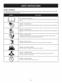
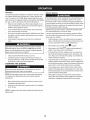
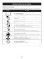
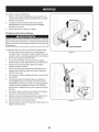
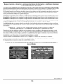
SAFETY
SYMBOLS
This pagedepictsand describessafetysymbolsthat mayappear on this product. Read,understand,and followall instructionson the machine
beforeattemptingto assembleand operate.
.i
+
i
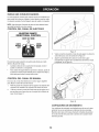
READ THE OPERATOR'S MANUAL(S)
Read, understand,
and follow
all instructions
in the manual(s) before
attempting
to assemble
and
operate
WARNING--
ROTATING BLADES
Keep hands out of inlet and discharge openings
inside
WARNING--
machine is running. There are rotating
blades
while
machine is running. There are rotating
blades
ROTATING BLADES
Keep hands out of inlet and discharge openings
inside
WARNING--
ROTATING AUGER
Do not put hands or feet near rotating
Contact
while
with the rotating
parts, in the auger/impeller
parts can amputate
housing
or chute assembly.
hands and feet.
"JIp
WARNING--THROWN
This machine
OBJECTS
may pick up and throw objects
WARNING--GASOLINE
WARNING--
injury.
before refueling.
CARBON MONOXIDE
Never run an engine indoors
monoxide,
can cause serious personal
IS FLAMMABLE
Allow the engine to cool at least two minutes
WARNING--
which
or in a poorly ventilated
an odorless and deadly gas+
ELECTRICAL SHOCK
Do not use the engine's
electric starter in the rain
6
area. Engine exhaust contains carbon
Thispageleftintentionally
blank.
7
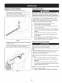
NOTE:Referencesto rightor left sideof the snowthrowerare
determinedfrom behindthe unit in the operatingposition(standing
directlybehindthe snow thrower,facingthe handlepanel).
REMOVING
1.
2.
3.
FROM CARTON
Cut the cornersof thecarton and lay the sidesflat on the ground.
Removeand discard all packinginserts.
Movethe snowthrowerout of thecarton.
Makecertainthe carton has beencompletelyemptiedbefore
discardingit.
ASSEMBLY
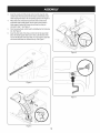
1.
Observethe lowerreararea of the snowthrowerto be sure both
cablesare alignedwith rollerguidesbeforepivotingthe handle
upward.
a.
b.
Placethe shiftleverin the F6position.
Pull up and back on upperhandleas shownin Figure1.As
youare raisingthe handleupward,make surethat bothends
of the centercableare positionedproperlyin the brackets.
See Figure2. Align upper handlewith the lowerhandle.
Figure2
c.
2.
Tightenhandknobs securingupper handleto lowerhandle.
Removeand discard any rubberbands,if present.Theyare
for packagingpurposesonly.
Removecotter pin,wingnut, and hexscrewfromchute control
headand clevis pin and bow-tiecotterpin from chutesupport
bracket.See Figure3.
Chute Control Head
Figure3
Figure1
8
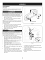
3.
4.
5.
6.
insert the roundend of the chute controlrod into inputof chute
controlhead.Pushrod as far intothe chutecontrol headas possible,keepingthe holesin the rod pointingupward.See Figure4.
Placechuteontochute baseand ensurechute control rodis
positionedunderhandle panel.Securechutecontrol headto
chutesupport bracketwith clevispin and bow-tiecotterpin
removedin step 1.See Figure5.
Finishsecuringchutecontrolhead by installinghex boltand wing
nut. See Figure6.
insert the otherend of the chutecontrol rod intothe inputshaft
belowthe handlepanel.Makesureto line up the flat end of the
rod and the fiat end of the input shaft.Youmay need to rotatethe
rod arounduntilthese two surfacesline up. See Figure7.
f
J
Figure6
,/
/
/
/
i'_.....................
......
i
,J
Figure4
Figure7
J
Figure5
9
7.
Pushthe chute controlrod towardthecontrol paneluntil the hole
in the rod lines up with the middlehole in the chutecontrol input
and insertthe cotterpin. See Figure8.
NOTE:Thereis a referencehole providedat rearend of controlrod to
help knowwhenholesare vertical.
NOTE:The holefurthestfrom the chutecontrol headis usedto
achievefurtherengagementof thechute controlrod intothe inputshaft
if required.Referto the Maintenance& Adjustmentssectionfor Chute
ControlRodadjustment.
The hole closestto the chutecontrol headis usedfor manual
movementof the chuteassemblyif required.Referto the Controls&
Featuressection.
8. Checkthat the cablesare properlyroutedthroughthecableguide
on topof the engine.See Figure9.
NOTE:For smoothestoperation,the cablesshouldall be to the left of
the chute controlrod.
9. The extensioncordfor the electricstarteris fastenedwith a cable
tie to the rearof the auger housingfor shippingpurposes.Cut the
cable tie and removecord beforeoperatingthe unit.
Figure9
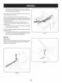
SET-UP
Shear
f
Pins
Holesare locatedin the handlepanelfor convenientshearpin storage.
See Figure10.Refertothe Operationsectionfor moreinformation
regardingshearpin replacement.
Figure10
J
Figure8
10
Chute
Clean-Out
Tool
f
A chute clean-outtool is fastenedto the top of theauger housing
with a mountingclip. See Figure11.Thetool is designedto cleara
chuteassemblyof iceand snow.This item is fastenedwith a cabletie
at the factory.Cut the cabletie beforeoperatingthe snowthrower.
Neveruseyourhandsto cleara cloggedchuteassembly.Shut
loft engineand remainbehindhandlesuntilall movingparts have
I stoppedbeforeusingtheclean-outtool to clearthe chuteassembly.
Drift
1.
2.
3.
Cutters
Removethetwo screwsand wing knobsthat secureeachdrift
cutter,and removethem from the sidesof the auger housing.
Turnthe drift cutters aroundand positionthemas shownin Figure
12to theoutside of the augerhousing.
Attachthedrift cutterswith the screwsand wingknobs removed
earlier.See Figure13.
/
/
J
Figure12
Tire Pressure
Underanycircumstancedo notexceedmanufacturer'srecommendedpsi. Equaltire pressureshouldbe maintainedat all times.
Excessivepressurewhenseatingbeadsmay causetire/rim
assemblyto burstwith force sufficientto causeseriousinjury. Refer
to sidewallof tirefor recommendedpressure.
Thetires are over-inflatedfor shippingpurposes.Checkthe tire
pressurebeforeoperatingthe snow thrower.Referto the tire sidewall
for tire manufacturer'srecommendedpsi and deflate(or inflate)the
tires as necessary.
NOTE:Equaltire pressureis to be maintainedatall timesfor performancepurposes.
Figure13
Figure11
11
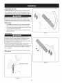
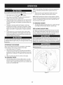
ADJUSTMENTS
Skid Shoes
The snowthrowerskid shoesare adjustedupwardat thefactory for
shippingpurposes.Adjustthemdownward,if desired,priorto operatin the snowthrower.
you operate
snow
on
Smooth
Surface
Uneven
Surface
gravel
as itcan easilypick up and throw loosegravel,causingpersonal
lit is not recommendedthat
this
thrower
injuryor damageto the snowthrowerand surroundingproperty.
•
Forclose snow removalon a smoothsurface,raiseskid shoes
higheron the auger housing.
•
Use a middleor lowerpositionwhenthearea to be clearedis
uneven,such as a graveldriveway.
NOTE:If youchooseto operatethe snowthroweron a gravelsurface,
keepthe skid shoesin positionfor maximumclearancebetweenthe
groundand the shaveplate.
Toadjustthe skid shoes:
1.
2.
3.
Figure14
Loosenthe four hexnuts (two on each side)and carriagebolts.
Moveskid shoesto desiredposition.See Figure14.
Makecertainthe entirebottomsurfaceof skid shoeis againstthe
groundto avoidunevenwearon the skid shoes.
Retightennuts and boltssecurely.
Auger Control
Priorto operatingyoursnow thrower,carefullyread and followall
instructionsbelow.Performall adjustmentsto verifyyoursnow
throweris operatingsafelyand properly.
Checkthe adjustmentof the augercontrolas follows:
1. Theauger controlis locatedon the left handle.See Figure15
inset.Whentheauger controlis releasedand in the disengaged
"up"position,the cableshouldhavevery little slack. It should
NOTbe tight.
2.
3.
4.
5.
6.
In a well-ventilatedarea,start the snowthrowerengine.Referto
Startingthe Enginein the Operationsection.
Whilestandingin the operator'sposition(behindthesnow
thrower),engagethe augers.
Allowthe augersto remainengagedfor approximatelyten (10)
secondsbeforereleasingthe auger control.Repeatthis several
times.
7.
Withthe auger controlin the disengaged"up" position,walkto the
frontof the machine.
8.
Figure15
To readjustthe controlcable,loosenthe upper hexbolton the
augercable bracket.See Figure15.
Positionthe bracketupwardto providemoreslack(or downward
to increasecabletension).
9. Retightenthe upperhex bolt.
10. Repeatsteps2-6 aboveto verifyproperadjustmenthas been
achieved.
Confirmthat the augershavecompletelystoppedrotatingand
show NOsigns of motion.If anyauger showsANYsign of
rotating,immediatelyreturnto the operator'spositionand shutoff
theengine.Waitfor ALL movingparts to stop beforeadjustingthe
augercontrol.
12
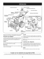
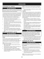
f
Shift Lever
Drive Control
Electric Chute Control
(Joystick)
Headlight
Auger Control
\\
Manual
Gas Cap \
ChuteAssembly
\
ChuteControl\
\.
Wheel Steering Control
\
Drift Cutter
Recoil Starter
Oil Fill
Handle
Clean Out
Tool
\
Auger
Housing
Skid Shoe
Oil Drain
J
Figure16
THROTTLE
Nowthat you haveset up your snowthrower,it'simportantto become
acquaintedwith its controlsand features.Referto Figure16.
SHIFT
LEVER
6
Theshift leveris locatedon the rightsideof the handlepanel.
5
Placethe shiftleverintoany of eight positionsto control the
directionof traveland groundspeed,
Forward
4
PRIMER
Depressingthe primerforcesfueldirectlyintothe engine'scarburetor
to aid in cold-weatherstarting.
R1
OIL FILL
R2
CHOKE
The throttlecontrol is locatedon the rear of the engine.It regulatesthe
speedof the engineand will shut off the enginewhen movedinto the
STOPposition.
3
Yoursnowthrowerhas six forward(F) speeds.Positionone (1)is t 2
the slowestand positionsix (6) is thefastest.
F1
Reverse
Yoursnowthrowerhastwo reverse(R) speeds,One (1) is the
slowerand two (2) is the faster.
CONTROL
Engineoil levelcan be checkedand oil addedthroughthe oil fill.
CONTROL
ELECTRIC
Thechokecontrol is foundon the rear of the engineand is activated
by turningthe rotarychoke knobto the CHOKEposition.Activating
the chokecontrolclosesthe chokeplateon the carburetorand aids in
startingthe engine.
STARTER
BUTTON
Pressingtheelectricstarterbuttonengagesthe engine'selectric
starterwhenpluggedintoa 120Vpowersource.
Meets ANSi Safety Standards
CraftsmanSnowThrowersconformtothe safetystandardof the AmericanNationalStandardsInstitute(ANSI).
13
ELECTRIC STARTER OUTLET
DRIVE CONTROL/AUGER
Requiresthe useof a three-prongoutdoorextensioncord(included)
and a 120Vpowersource/walloutlet.
f
CONTROL
LOCK
DRIVE
CONTROL
KEY
The keyisa safety device.It mustbe fully insertedin orderfor the
engineto start. Removethe keywhenthe snowthroweris notin use.
NOTE:Do notturn the key in an attemptto startthe engine.Doingso
may causeit to break.
.
AUGERS
Whenengaged,the auger bladesrotateand draw snowinto theauger
housing.
Positionthe skid shoes basedon surfaceconditions.Adjust upward
for hard-packedsnow.Adjustdownwardwhenoperatingon gravelor
crushedrock surfaces.
DRIFT CUTTERS
NOTE:Alwaysreleasethedrivecontrol beforechangingspeeds.
Failureto do so will resultin increasedwearon your machine'sdrive
system.
Thedrift cuttersare designedfor use in deep snow.Theiruse is
optionalfor normalsnowconditions.Maneuverthe snowthrowerso
that the cutterspenetratea high standingsnow drift to assist snow
fallingintothe augersfor throwing.
ELECTRIC
f
HEADLIGHT
The headlightis on whenevertheengine is running.
STEERING
.
The drivecontrolis locatedon the righthandle.Squeezethe control
grip againstthe handleto engagethe wheeldrive.Releaseto stop.
The drivecontrolalso lockstheauger controlso youcan operate
the chutedirectionalcontrolwithoutinterruptingthe snowthrowing
process.If theauger controlis engagedsimultaneouslywith thedrive
control,theoperatorcan releasethe augercontrol (on the left handle)
and the augerswill remainengaged.Releasebothcontrolsto stop the
augersand wheeldrive.
SKiD SHOES
WHEEL
@
CHUTE CONTROL
ELECTRIC
DiRECTiONAL
CHUTE
CONTROL
CONTROLS
The left and rightwheelsteeringcontrolsare locatedon the underside
of the handles.Squeezethe rightcontrolto turn right; squeezethe left
controlto turn left.
CHUTE
ROTATE
LEFT
NOTE:Operatethe snowthrowerin open areasuntilyou are familiar
with thesecontrols.
CHUTE
ROTATE
RIGHT
AUGER CONTROL
f
The electricchutecontrol(Joystick)is locatedon the rightside of the
handle panel.
*
*
Theauger controlis locatedon the left handle.Squeezethecontrol
grip againstthe handleto engagetheauger and start snowthrowing
action.Releaseto stop.
14
Tochangethe directionin which snowis thrown,movethe
joystickto the rightor tothe left.
Tochangethe angle/distancewhich snowis thrown,pivotthe
joystickforwardto tilt the chutedownand backwardto tilt the
chute up.
MANUAL CHUTE CONTROL
CLEAN-OUT
TOOL
Proceedas followsto utilizethe manualchutecontrol:
1.
Removethecotterpin fromeitherof the holesfurthestfrom the
chuteassemblyon the chutecontrol head.
2.
Pushin the chute controlrod untilthe holein it lines up with the
thirdhole in thechute controlhead. See Figure17.
Neveruse yourhandsto cleara cloggedchute assembly.Shut
Ioff engine and remainbehindhandlesuntilall movingparts have
[stoppedbeforeusingthe clean-outtoolto clearthe chute assembly.
f
The chuteclean-outtool is convenientlyfastenedto the rearof the
auger housingwith a mountingclip. Shouldsnowand ice become
lodgedin the chute assemblyduringoperation,proceedas followsto
safelycleanthe chuteassemblyand chuteopening:
1. Releaseboththe AugerControland the Drive Control.
2.
3.
4.
5.
/
,/
......
.........
/
i
/
6.
Stoptheengine by removingthe ignitionkey.
Removethe clean-outtool from the clipwhich securesit to the
rearof the auger housing.
Usethe shovel-shapedend of the clean-outtoolto dislodgeand
scoopanysnow and ice whichhas formedin and nearthe chute
assembly.
Refastenthe clean-outtoolto the mountingclip on the rearof
the auger housing,reinsertthe ignitionkeyand startthe snow
thrower'sengine.
Whilestandingin theoperator'sposition(behindthe snow
thrower),engagethe augercontrolfor a few secondsto clearany
remainingsnowand icefrom the chuteassembly.
Figure17
3.
Reinsertthe cotterpin throughthis hole and thechute controlrod
as shownin Figure17.
4.
Graspthe indentedportionof the chute controlrod and manually
rotatethe chuteto the rightor to the left. See Figure18.
BEFORE
STARTING
ENGINE
Read,understand,and followall instructionsand warningson the
machineand in this manualbeforeoperating.
Oil
The unit was shippedwith oil in the engine.Checkoil levelbefore
eachoperationto ensureadequateoil in theengine.Forfurther
instructions,referto the stepson page 18.
/
/
/
NOTE:Be sureto checkthe engineon a levelsurfacewith theengine
stopped.
1. Removethe oil filler cap/dipstickand wipe thedipstickclean.
2. insertthe cap/dipstickintothe oil filler neck,and tightenthe cap
untilseated.
/
i/
i//'
I
3.
Removethe oil filler cap/dipstick,ifthe levelislow,slowlyadd
oil (5W-30,with a minimumclassificationof SF/SG)untiloil level
registersbetweenhigh (H) and low(L).
NOTE:Donot overfill.Overfillingwith oil may resultin enginesmoking,
hardstartingor sparkplug fouling.
4. Replaceand tightencap/dipstickfirmly beforestartingengine.
Figure18
15
Gasoline
Electric
Use automotivegasoline(unleadedor low leadedto minimizecombustionchamberdeposits)with a minimumof 87 octane.Gasolinewith
up to 10%ethanolor 15%MTBE(MethylTertiaryButyl Ether)canbe
used. Neverusean oil/gasolinemixtureor dirty gasoline.Avoidgetting
dirt, dust,or waterin thefuel tank. DO NOTuse E85gasoline.
•
Refuelin a well-ventilatedareawith the engine stopped.Donot
smokeor allowflamesor sparksin the area wheretheengine is
refueledor wheregasolineisstored.
Do notoverfillthe fuel tank.After refueling,makesurethe tank
cap is closedproperlyand securely.
Be carefulnot to spillfuel when refueling.Spilledfuelor fuelvapor
may ignite.If any fuel isspilled,makesurethe area isdry before
startingtheengine.
•
•
•
Avoidrepeatedor prolongedcontactwith skin or breathingof
vapor.
Useextremecare whenhandlinggasoline.Gasolineis extremely
flammableand the vaporsare explosive.Neverfuelthe machine
indoorsor while theengine ishotor running.Extinguishcigarettes,
cigars,pipesand other sourcesof ignition.
1.
Cleanaroundfuelfill beforeremovingcap to fuel.
2.
A fuel levelindicatorislocatedinthe fuel tank.See Figure15
inset.Be carefulnot to overfill.Filltank untilfuel reachesthe fuel
The optionalelectricstarteris equippedwith a groundedthree-wire
powercordand plug,and is designedto operateon 120volt AC
householdcurrent.It mustbe usedwith a properlygroundedthreeprong receptacleat all timesto avoidthe possibilityof electricshock.
Followall instructionscarefullyprior to operatingtheelectricstarter.
DONOTuse electricstarterin the rain.
Determinethat yourhome'swiringis a three-wiregroundedsystem.
Ask a licensedelectricianif you are notcertain.
If you havea groundedthree-prongreceptacle,proceedas follows.
If you do not havethe properhousewiring, DONOT usethe electric
starterunder anyconditions.
1. Plugthe extensioncord intothe outlet locatedon the engine's
surface.Plug the otherend of extensioncord intoa three-prong
120-volt,grounded,AC outlet in a well-ventilatedarea.
2.
Movethrottlecontrolto FAST(rabbit)_
3.
Movechoketo the CHOKEI,'1¢1position(coldengine start). If
engine is warm,placechoke in RUNposition.
4.
Pushprimerthree(3) times,makingsureto cover vent hole in
primerbulb whenpushing.If engine is warm,pushprimeronly
once. Alwayscovervent hole whenpushing.Cool weathermay
requireprimingto be repeated.
Pushstarterbuttonto startengine.Oncetheengine starts,immediatelyreleasestarterbutton.Electricstarteris equippedwith
thermaloverloadprotection;systemwill temporarilyshut-downto
allow starterto cool if electricstarterbecomesoverloaded.
5.
levelindicator
to allow spacefor fuelexpansion.
STARTING
THE ENGINE
6.
>ressurized
startingfluid. Vaporsare flammable.
NOTE:Allowtheengineto warmup for a few minutesafter starting.
Theenginewill not developfull poweruntil it reachesoperating
temperatures.
1.
2.
7.
Makecertain boththe augercontroland drivecontrolare in the
disengaged(released)position.
Insertkey into slot.Makesureit snapsinto place.Do notattempt
to turnthe key.
NOTE:The enginecannotstart withoutthe key fully insertedintothe
ignitionswitch.
16
Starter
position.
As the enginewarms,slowlyrotatethechoke controlto RUN
position.If the enginefalters, restartengineand runwith choke
at half-chokepositionfor a shortperiod of time,and thenslowly
rotatethe choke intoRUNposition.
After engineis running,disconnectpowercord fromelectric
starter.Whendisconnecting,alwaysunplugthe end at the wall
outlet beforeunpluggingthe oppositeend fromthe engine.
Recoil Starter
NOTE: When selectinga DriveSpeed,use the slowerspeedsuntil
you are comfortableand familiarwiththe operationof the snow
thrower.
2. Squeezethe drivecontrolagainstthe handleand the snow
throwerwill move.Releaseitand drive motionwill stop.
Do notpull the starterhandlewhilethe engine running.
1.
Movethrottlecontrolto FAST(rabbit)d_J_ position.
2.
Movechoketo the CHOKE I#1 position(coldenginestart). If
engineis warm,placechokein RUNposition.
3.
Pushprimerthree (3) times, makingsureto covervent hole when
pushing.If engine iswarm,push primeronlyonce. Alwayscover
vent holewhen pushing.Coolweathermay requireprimingto be
repeated.
Pull gentlyon the starterhandleuntil itbeginsto resist,then
pull quicklyand forcefullyto overcomethe compression.Engine
shouldstart. Donot releasethe handleand allow itto snapback.
Returnrope SLOWLYto originalposition.If required,repeatthis
step.
4.
5.
NOTE:NEVERrepositionthe shiftlever(changespeedsor direction
of travel)withoutfirst releasingthe drivecontrol and bringingthe snow
throwerto a completestop.Doingsowill resultin prematurewearto
the snow thrower'sdrivesystem.
TO ENGAGE
1.
THE ENGINE
Alwaysturn off thesnow thrower'sengineand removethe key priorto
replacingshearpins.
Removethekey.Removingthe key will reducethe possibilityof
unauthorizedstartingof the enginewhileequipmentis notin use.
Keepthe key in a safe place.The enginecannotstart withoutthe
key.
Wipeany moistureawayfrom the controlson theengine.
TO ENGAGE
1.
PINS
NEVERreplacethe augershearpinswith anythingotherthan Sears
SKU#88389/0EM PartNo. 738-04124Areplacementshearpins.
Anydamageto theauger gearboxor other componentsas a resultof
failingto do sowill NOTbe coveredbyyour snowthrower'swarranty.
After youhavefinishedsnow-throwing,run enginefora few minutes
beforestoppingto help dry off any moistureon the engine.
1. Movethrottlecontrolto OFF position.
3.
SHEAR
The augersare securedto the spiralshaftwith shearpins and cotter
pins.If the augersshouldstrikea foreignobject or ice jam,the snow
throweris designedso that the pins mayshear.If theaugerswill not
turn, checkto see if the pins havesheared.See Figure19.
To avoidunsupervisedengineoperation,neverleavethe machine
unattendedwith the engine running.Turnthe engineoff after use and
removekey.
2.
Toengagethe augerand startthrowingsnow,squeezethe auger
controlagainstthe left handle.Releaseto stopthe auger.
REPLACING
As theenginewarms,slowlyrotatethe chokecontrol to RUN
position.If the enginefalters,restartengineand run with choke
at half-chokepositionfor a short periodof time,and then slowly
rotatethe chokeintoRUNposition.
STOPPING
AUGER
DRIVE
With thethrottlecontrolin the Fast(rabbit)position,moveshift
leverintoone of the six forward(F) positionsor two reverse(R)
positions.Select a speedappropriatefor the snowconditionsand
a paceyou'recomfortablewith.
J
Figure19
17
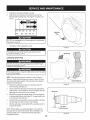
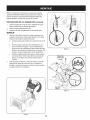
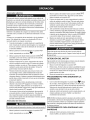
MAINTENANCE
Beforeperforminganytype ofmaintenance/service,
disengageall
controlsand stoptheengine.Waituntilall movingpartshavecometo
a completestop.Disconnectsparkplugwireandgroundit againstthe
enginetopreventunintendedstarting.Alwayswearsafetyglassesduring
operationor whileperforminganyadjustmentsor repairs.
EachUseand every 5
hours
1st5 hours
SCHEDULE
Followthe maintenanceschedulegiven below.This chart describes
serviceguidelinesonly. Usethe ServiceLog columnto keeptrackof
completedmaintenancetasks.To locate the nearest Sears Service
Centeror to scheduleservice,simplycontactSearsat
1-800-4-MY-HOME®.
1.
Check
Unit and engine.
2.
3.
Tightenor replace
Clean
1.
Engineoil
1.
Change
1.
2.
Engineoil level
Looseor missinghardware
3.
1.
Sparkplug
1.
Check
2.
3.
Controllinkagesand pivots
Wheels
2.
3.
Lubewith light oil
Lubewith multipurposeautogrease
4.
Gear shaftand Augershaft
4.
Lubewith light oil
Annuallyor 50 hours
1.
Engineoil
1.
Change
Annuallyor 100 hours
1.
Sparkplug
1.
Change
BeforeStorage
1.
Fuelsystem
1.
Runengineuntilit stopsfrom lack
d fuel
Annuallyor 25 hours
ENGINE
Checking
MAINTENANCE
Engine
Oil
Beforelubricating,repairing,or inspecting,disengageall controls
Iand stop engine.Wait untilall movingpartshavecometo a complete
_stop.
NOTE: Checktheoil levelbeforeeachuseto be surecorrectoil level
is maintained.
Whenaddingoil to the engine,referto viscositychart below.Engine
oil capacityis 1100ml (approx.37 oz.). Donot over-fill.Usea 4-stroke,
or an equivalenthighdetergent,premiumquality motoroil certified
to meet or exceedU.S.automobilemanufacturer'srequirementsfor
serviceclassificationSG, SR MotoroilsclassifiedSG, SFwill show
this designationon the container.
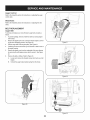
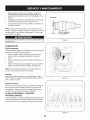
1. Removethe oil fillercap/dipstickand wipethe dipstickclean.
2.
3.
4.
Insertthe cap/dipstickintothe oil filler neck,and tightenthe cap
until seated.
J
Removethe oil fillercap/dipstick.If levelis low, slowlyadd oil until
oil levelregistersbetweenhigh (H) and low (L). See Figure20.
Replaceand tighten cap/dipstickfirmlybeforestartingengine.
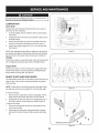
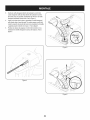
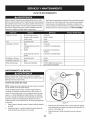
Changing
Engine
Oil
NOTE:Changethe engineoil after the first5 hoursof operationand
oncea seasonor every 50 hoursthereafter.
1. Drainfuelfrom tank by runningengineuntilthe fuel tank is empty.
Be surefuel fill cap is secure.
18
Figure20
2.
3.
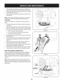
Placesuitableoil collectioncontainerunderoil drain plug.
Removeoil drain plug.See Figure21 on next page.
4.
Tip unit to drainoil intothe container.Usedoil mustbe disposed
of at a propercollectioncenter.
Usedoil is a hazardouswasteproduct.Disposeof usedoil properly.
IDo notdiscardwith householdwaste.Checkwith your localauthorilties or SearsService Centerfor safe disposal/recyclingfacilities.
.
6.
Reinstallthe drain plugand tightenit securely.
Refillwith the recommendedoil and checkthe oil level.See
RecommendedOil Usagechart.Theengine'soil capacityis 37
ounces.
i
u
[
(%-40 °-20 o 0o 200 400
("c)
Oil Drain
Plug
-300 -200 -10° 0°
DO NOTuse nondetergentoil or 2-strokeengineoil. It could shorten
the engine'sservicelife.
7.
Reinstallthe oil fillercap/dipsticksecurely.
Figure21
Thoroughlywashyour handswith soap andwater as soonas
possibleafter handling usedoil.
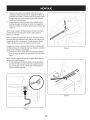
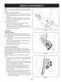
Checking
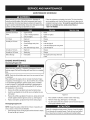
Spark
Spark Plug
Plug
O
DO NOTcheckfor sparkwith spark plug removed.DO NOTcrank
engine with sparkplug removed.
If the enginehas been running,the mufflerwill be very hot. Be careful
notto touch the muffler.
NOTE: Checkthe sparkplug oncea seasonor every 25 hoursof
operation.Changethe sparkplug oncea seasonor every 100hours.
Toensureproperengine operation,the sparkplug mustbe properly
gappedand freeof deposits.
1.
2.
3.
4.
5.
J
Figure22
Removethespark plug bootand use a sparkplug wrenchto
removethe plug.See Figure22.
Visuallyinspectthe spark plug.Discardthe spark plug if thereis
apparentwear,or if the insulatoris crackedor chipped.Cleanthe
sparkplug with a wirebrush if it is to be reused.
Electrode
Measurethe plug gap with a feelergauge.Correctas necessary
by bendingsideelectrode.See Figure23. Thegap shouldbe set
to .02-.03inches(0.60-0.80ram).
Checkthatthe sparkplug washeris in good conditionand thread
the sparkplug in by handto preventcross-threading.
After thespark plug is seated,tightenwith a spark plugwrenchto
compressthe washer.
NOTE:Wheninstallinga newsparkplug,tighten 1/2-turnafter the
sparkplug seatsto compressthe washer.Whenreinstallinga used
sparkplug,tighten 1/8-to 1/4-turnafter the sparkplug seatsto
compressthe washer.
.02-.03 in.
{0.60-0.80 ram)
Figure23
19
hotandcan
ine.
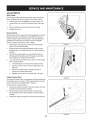
LUBRICATION
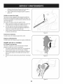
Gear Shaft
Thegear (hex)shaft shouldbe lubricatedat least oncea seasonor
afterevery 25 hoursof operation.
1. Topreventspillage,removeall fuel fromtank by runningengine
until it stops.
2.
3.
4.
Carefullypivotthe snowthrowerup and forwardso that it restson
theauger housing.
Removethe lowerframecover fromthe undersideof the snow
throwerby removingthe self-tappingscrewswhich secureit.
Applya lightcoatingof engineoil (or 3-in-1oil) to the hexshaft.
See Figure24.
)
//
{;:7/
Figure24
f
At least oncea season,removebothwheels.Cleanand coat theaxles
with a multipurposeautomotivegreasebeforereinstallingwheels.
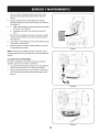
Auger Shaft
At least oncea season,removethe shearpinson augershaft. Spray
lubricantinsideshaft,and aroundthe spacersand flangebearings
foundat eitherend of the shaft. See Figure25.
PLATE AND SKID SHOES
The shaveplateand skid shoeson the bottomof the snowthrowerare
subjectto wear.They shouldbe checkedperiodicallyand replaced
whennecessary.
NOTE:Theskid shoeson this machinehavetwo wearedges.When
one sidewears out, theycan be rotated1800to usethe otheredge.
Figure25
f
To removeskid shoes:
1.
Removethe two carriagebolts,washers(if equipped),and hex
flangenutsthat secureeach skid shoeto the snowthrower.
2.
Reassemblenew skid shoeswith the fourcarriagebolts (two on
eachside), washers,and hex flangenuts.Referto Figure26.
To removeshaveplate:
1.
2.
"?X
)
7/' ................
NOTE:Whenlubricatingthe hexshaft, be carefulnotto get any oil on
thealuminumdriveplateor rubberfrictionwheel. Doingsowill hinder
the snowthrower'sdrive system.Wipeoff anyexcessor spilledoil.
Wheels
SHAVE
/ ....
Removethe carriageboltsand hexnuts whichattachit to the
snowthrowerhousing.
Reassemblenew shaveplate,makingsureheadsof carriage
bolts are to the insideof housing.Tightensecurely.See Figure
26.
Figure26
2O
ADJUSTMENTS
Shift Cable
If thefull rangeof speeds(forwardand reverse)cannotbe achieved,
referto the figureto the rightand adjustthe shift cableas follows:
1. Placethe shiftleverin thefastest forward speedposition(F6).
2. Loosenthe hex nuton the shiftcable indexbracket.See Figure
27.
3.
4.
Pivotthe bracketdownwardto take up slack in the cable.
Retightenthehex nut.
Drive
Control
Whenthedrivecontrol is releasedand in thedisengaged"up"position,
the cableshouldhavevery little slack.It shouldNOTbe tight. Also,
if thereis excessiveslackin thedrive cableor if the unitexperiences
intermittentdrivewhileusing,the cable mayneed to be adjusted.
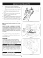
Checktheadjustmentof the drivecontrolas follows:
1. With thedrivecontrol released,pushthe snowthrowergently
forward.The unitshouldroll freely.
2.
3.
4.
J
Figure27
f
Engagethe drivecontroland gently attemptto pushthe snow
throwerforward.Thewheelsshouldnotturn. The unitshouldnot
roll freely.
With thedrivecontrol released,movethe shift leverbackand
forth betweenthe R2positionand the F6 positionseveraltimes.
Thereshouldbe no resistancein the shiftlever.
If anyof the abovetests failed,the drivecable is in needof adjustment.Proceedas follows:
a.
b.
Shutoff theengineas instructedin the Operationsection.
Loosenthe lowerhexbolt on the drivecable bracket.See
Figure28.
c.
Positionthe bracketupwardto providemoreslack(or
downwardto increasecabletension).
Retightenthe lowerhex boltand repeatsteps1 through4.
d.
Chute
Control
.........
Rod
Figure28
Toachievemorechutecontrolrod engagementin the input shaftunder
the handlepanelshownin Figure7 in the Assemblysection,the chute
controlrod will haveto be adjusted.Referto Figure29.
Toadjustthis rod,proceedas follows:
5.
6.
Removethecotterpin fromeitherof the holesclosestto thechute
assemblyon thechute rotationassembly.
Pull outthe chute controlrod untilthe holein it lines up with
the hole furthestfromthe chute assemblyon the chute rotation
assembly.
7.
Reinsertthe cotterpin throughthis hole and thechute controlrod.
21
.......
,f
Figure29
Auger Control
Referto the Assemblysectionfor instructions
on adjustingtheauger
controlcable.
f
;....
"_
Skid Shoes
Referto the Assemblysectionfor instructions
on adjustingthe skid
shoes.
BELT REPLACEMENT
Auger Belt
To removeand replaceyoursnow thrower'sauger belt, proceedas
follows:
1.
Topreventspillage,removeall fuel fromtank by runningengine
until itstops.
2.
Removethe plasticbelt coveron the front of the engineby removingthe two self-tappingscrews.See Figure30.
Rollthe auger beltoff theengine pulley.See Figure31.
3.
4.
5.
6.
J
Figure31
J
Carefullypivotthe snowthrowerup and forwardso that itrestson
theauger housing.
Removethe frame coverfrom the undersideof the snow thrower
by removingthe self-tappingscrewswhich secureit. See Figure
32.
Removethe beltas follows.Referto Figure33.
A. Loosenand removethe shoulderscrewwhich actsas a belt
B.
keeper.
Unhookthe auger brakebracketspringfrom the frame.
f
Figure32
f
Figure30
J
Figure33
22
7. Remove
thebeltfromaround
theauger
pulley,
andslipthebelt
between
thesupport
bracket
andtheauger
pulley.
SeeFigure
34.
8. Reassemble
auger
beltbyfollowing
these
instructions
inopposite
order
andmanner
ofremoval.
9. Perform
theAuger
Control
testoutlined
intheAssembly
section
ofthismanual.
iO
i
NOTE:
DoNOT
forget
toreinstall
theshoulder
screw
andreconnect
thespring
totheframe
afterinstalling
areplacement
auger
belt.
Drive Belt
Toremoveand replaceyoursnow thrower'sdrivebelt, proceedas
follows:
1.
Topreventspillage,removeall fuel fromtank by runningengine
untilit stops.
2.
Removetheplasticbelt coveron the front of the engineby removingthe two self-tappingscrews.See Figure30 on previouspage.
Removethebelt from enginepulleyas follows. Referto Figure35.
3.
A.
B.
4.
5.
6.
7.
8.
Figure34
Rollthe auger beltoff theengine pulley.
Use a wrenchto pivotthe idlerpulleytowardthe right.
C. Lift the drivebelt off engine pulley.
Carefullypivotthe snowthrowerup and forwardsothat itrestson
the augerhousing.
Removetheframe coverfrom the undersideof the snowthrower
by removingthe self-tappingscrewswhich secureit. Referto
Figure32.
///
Back outthe stop bolt to increasethe clearancebetweenthe
frictionwheeldisc and frictionwheel.See Figure36.
Slip the drivebelt off the frictionwheeldisc and betweenfriction
wheeland frictionwheeldisc.See Figure36.
Reassembledrive beltby followingthese instructions
in opposite
orderand mannerof removal.Be sureto reinstallthe stop bolt.
FRICTION
WHEEL
INSPECTION
If the snowthrowerfails to drivewith thedrivecontrolengaged,and
performingthe DriveControlCableAdjustmentfails to correctthe
problem,the frictionwheelmay needto be replaced.Examinethe
frictionwheelrubberfor signsof wearor crackingand replacewheelif
necessary.
J
Figure35
f
NOTE:Severalcomponentsmustbe removedand specialtools are
requiredin order to replacethis snowthrower'sfrictionwheel. If your
frictionwheelneedsto be replaced,contactthe nearestSearsParts&
RepairCenter.
Frictio_
Friction
Wheel Disc
Stop
Figure36
23
If the snowthrowerwillnot be usedfor30 daysor longer,or if it is the end of the snowseasonwhenthe last possibilityof snowis gone,the
equipmentneedsto be storedproperly.Followstorageinstructionsbelowto ensuretop performancefrom the snowthrowerfor manymoreyears.
PREPARING
PREPARING
ENGINE
Whenstoringthe snowthrowerin an unventilatedor metal storage shed,careshouldbe taken to rustprooftheequipment.Using
a light oil or silicone,coat theequipment,especiallyanychains,
springs,bearingsand cables.
Enginesstoredover30 days need to be drainedof fuel to prevent
deteriorationand gumfrom formingin fuel systemor on essential
carburetorparts.If thegasolinein yourenginedeterioratesduring
storage,youmay needto havethe carburetor,and otherfuel system
components,servicedor replaced.
1.
2.
3.
Removeall fuel fromtank by runningengineuntil it stops. Donot
attemptto pourfuel from the engine.
Changethe engineoil.
Removesparkplug and pour approximately1 oz. (30 rnl) of clean
engineoil intothe cylinder.Pullthe recoilstarterseveraltimesto
distributetheoil, and reinstallthe spark plug.
4.
Cleandebrisfrom aroundengine,and under,around,and behind
muffler.Applya lightfilm of oil on anyareasthat are susceptible
to rust.
•
Storein a clean,dry and wellventilatedarea awayfrom anyappliancethat operateswith a flame or pilotlight, such as a furnace,
waterheater,or clothesdryer.Avoidany areawith a spark
producingelectricmotor,or wherepowertools are operated.
Neverstoresnow throwerwith fuel in tank indoorsor in poorlyventilatedareas,wherefuel fumesmay reachan openflame,spark or pilol
lightas on a furnace,water heater,clothesdryer or gas appliance.
•
•
SNOW THROWER
If possible,avoidstorageareaswith high humidity.
Keepthe enginelevelin storage.Tiltingcan causefuel or oil
leakage.
24
•
•
Removeall dirt fromexteriorof engineand equipment.
Followlubricationrecommendations.
•
•
Storeequipmentin a clean,dry area.
Inflatethe tiresto the maximumPSi. Referto tiresidewall.
Enginefails to start
1.
2.
Chokecontrolnot in CHOKEposition.
Sparkplugwire disconnected.
1.
2.
Movechokecontrolto CHOKEposition.
Connectwireto sparkplug.
3.
4.
5.
Faultysparkplug.
Fueltank emptyor stalefuel.
Enginenot primed.
3.
4.
5.
Clean,adjustgap,or replace.
Filltank with clean,freshgasoline.
Primeengineas instructedin the OperationSection.
6.
7.
Keynot inserted.
Extensioncordnot connected(when
usingelectricstartbutton,on modelsso
equipped).
6.
7.
Insertkeyfully intothe switch.
Connectone end of the extensioncordto the electric
starteroutletand the otherend to a three-prong
120-volt,grounded,ACoutlet.
Enginerunningerratically/
inconsistentRPM(huntingor
1.
2.
Enginerunningon CHOKE.
Stalefuel.
1.
Movechokecontrolto RUNposition.
surging)
3.
Wateror dirt in fuel system.
2.
3.
Filltank with clean,freshgasoline.
Drainfueltank by runningengineuntil it stops. Refill
with freshfuel.
4.
Over-governedengine.
4.
ContactyourSearsParts & RepairCenter.
Excessivevibration
1.
Loosepartsor damagedauger.
1.
Stopengineimmediatelyand disconnectsparkplug
wire.Tightenall boltsand nuts.If vibrationcontinues,
haveunit servicedbya SearsParts& RepairCenter.
Lossof power
1.
2.
Sparkplugwire loose.
Gascap vent hole plugged.
1.
2.
Connectand tightenspark plugwire.
Removeiceand snowfrom gascap. Be certainvent
hole is clear.
Unitfails to propel itself
1.
Drivecable in need of adjustment.
1.
Adjustdrivecontrolcable. Referto Serviceand
Maintenancesection.
2.
Drivebelt looseor damaged.
2.
Replacedrive belt. Referto Serviceand Maintenancesection.
3.
Wornfrictionwheel.
3.
Havefrictionwheelreplacedat a SearsParts &
RepairCenter.
1.
Chuteassemblyclogged.
1.
2.
Foreignobject lodgedin auger.
2.
Stopengineimmediatelyand disconnectsparkplug
wire.Cleanchute assemblyand insideof auger
housingwith clean-outtoolor a stick.
Stopengineimmediatelyand disconnectsparkplug
wire. Removeobjectfrom augerwith clean-outtool
or a stick.
3.
Augercablein needof adjustment.
3.
Adjustaugercontrolcable. Referto Assembly
section.
4.
Augerbelt looseordamaged.
4.
Replaceauger belt. Referto Serviceand Maintenancesection.
5.
Shearpin(s) sheared.
5.
Replacewith newshearpin(s).
Chuteassembledincorrectly.
1.
Disassemblechute controland reassembleas
directedin the Assemblysection.
Unitfails to dischargesnow
Chutefails to easily rotate 180 1.
degrees
NEED HORE HELP?
Yot,Fttfind. th_
answer
a!ld mo_e on ma_age_y_ifeocom
Find this and att your other product manua[s ontine.
Get answers from our team of home experts.
Get a personalized maintenance
Find information
p[an for your home.
and tools to he[p with home projects.
managemylife
b_e'_g_t_/_eyeu by Sea_s
25
_ for
free]
Craftsman
Snow Thrower
Model 247.883960
/
/
/
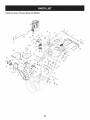
26
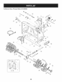
Craftsman
Snow Thrower
IViodel 247.883960
D =
731-2635
2.
0
0
D =
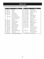
SnowRemovalToolMount
684-04057A-0637 ImpellerAssembly,12"Dia.
L Hex Screw,3/8-16, 1.75,Gr5
O
O
731-04870
Spacer,1.25OD x .75ID x 1.00
32.
736-0188
Washer,Flat,.76x 1.49x .06
33.
741-0493A
Bushing,Flange,.80ID x .91OD
3.
L710-0347
4.
710-0451
Bolt, Carriage,5/16-18,.750Grl
34.
790-00087A-0637 Housing,1"Hex Bearing
5.
710-04484
Screw, 5/16-18,0.750
35.
790-00119-0691
ShavePlate,2.25 x 29.66
731-05984A
Slide Shoe
6.
710-0703
Screw,Carriage,1/4-20,.750,Gr5
36.
7.
712-04063
Nut, FlangeLock,5/16-18,Nylon
37.
918-0123A
Housing,Auger,RH Reduced
8.
712-04064
Nut, FlangeLock,1/4-20,Nylon
38.
918-0124A
Housing,Auger,LH Reduced
9.
712-04065
Nut, FlangeLock,3/8-16,Nylon
39.
921-0338
Seal,Oil, .750x 1.00x .125
10.
714-04040
CotterPin,Bow-tie
40.
741-0662
Bearing,Flange,.75x 1.0x .59
41.
710-0642
Screw,Self-tapping,1/4-20,0.750
11. J 725-0157
l Cable,Tie, 3/16x .05x 7.4
12.
926-04012
Nut, Push-on,.25 Dia
42.
711-04282
Axle, Auger,30"
13.
731-07525
Chute,Adapter5" Dia
43.
914-0161
Key,Hi-pro3/16x 5/8
14.
732-04460
Spring,Extension,.38OD x 4.59
44.
715-04021
Pin, Dowel,.25 ODx 1.2
15.
736-0174
Washer,Wave,.625x .885x .015
45.
917-04126
Shaft,Worm .75OD
16.
736-0242
Washer,Bell, .340x .872x .060
46.
917-0528A
Gear,Worm20T
17.
946-04230A
ClutchCable,Auger,47.23"
47.
718-04071
Collar,Thrust
18.
931-2643
SnowRemovalTool
48.
721-0325
Plug, 1/4x .437
19.
738-0143
Screw,Shoulder,.498x .34,3/8-16
49.
721-0327
Seal,Oil, .75x 1 x .131
20.
938-0281
Screw,Shoulder,.625x .17,3/8-16
50.
936-0351
Washer,Flat,.760ID x 1.50D
21.
738-04124A
ShearPin, .25x 1.50
51.
736-3084
Washer,Flat,.51x 1.12
22.
941-0245
Bearing,Hex Flangex .75ID
52.
741-0663
Bearing,Flange,.75x 1.0x .925
23.
941-0309
Bearing,Ball,.75 ID x 1.85OD
53.
741-0661A
Bearing,Flange,.75x 1.00x .975
24.
756-04224
Flat Pulley,Idler, 2.75OD
54.
929-0071A
ExtensionCord, 110V
25.
790-00075
Housing,Bearing,1.85ID
55.
790-00181-0637
Drift Cutter
26.
790-00080B
Bracket,Auger Idlerw/Brake
56.
731-04871
Spacer,1.25OD x .75ID x 3/16
27.
918-04165A
GearboxAssembly,Auger,30"
57.
920-0284
Wing Nut
28.
684-04267-0691
HousingAssembly,Auger30"
58.
936-0159
Washer,Fiat,.349x .879x .063
29.
684-04107-4028
SpiralAssembly,LH
59.
710-0276
Scr.,Crg.,5/16-18x 1.00
30.
684-04108-4028
SpiralAssembly,RH
L
27
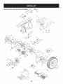
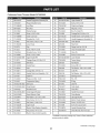
Craftsman
Snow Thrower
Model
247.883960
_o_19_.
_i/.o_
/
42i
28
D_
i
B
O ¸
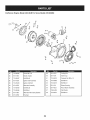
710-1652
AB Screw,1/4-20x 0.625
2.
731-06401
BeltCover
3.
735-04099
4.
711-1268B
5.
m _
O
684-04159
FrictionWheelAssembly
43.
716-0136
RetainerRing
Plug,3/8 ID
44.
726-0221
Speed Nut
ActuatorShaft
45.
790-00183B-0637 WheelDrive Frame
946-04229B
DriveClutchCable
46.
756-04109
Auger Pulley
6.
732-04345
ExtensionSpring
47.
736-0505
FiatWasher
7.
790-002070
DriveClutchCableGuideBracket
48.
738-04439
ShoulderScrew
8.
684-04156A
Shift RodAssembly
49.
936-0119
LockWasher
9.
750-04474
AxleSupportTube
50.
684-04169
IdlerPulleyAssembly
10.
914-0126
Hi Pro Key
51.
790-00332-0637
Pit.,Cvr.
11.
735-04100
Plug,1/2 ID
52.
750-04571
Spacer
12.
917-04210
Gear,56T
53.
732-04308B
TorsionSpring
13.
941-0245
Hex FlangeBearing
54.
710-0672
HexScrew,5/16-24x 1.25
14.
790-00206A-0637 AugerClutchCableGuideBracket
55.
756-04252
PulleyHalf
15.
756-0625
CableRoller
56.
954-04201A
Belt,WheelDrive
16.
738-0924A
C Screw,1/4-28x 0.375
57.
710-0809
TT Screw,1/4-20x 1.25
618-04288
DoggAssembly- LH
58.
790-002080
DriveClutchIdlerBracket
17.
618-04287
DoggAssembly- RH
59.
748-04112B
ShoulderSpacer
18.
926-04012
Push-onNut
60.
932-0264
ExtensionSpring
19.
750-04477A
Spacer
61.
712-0417A
FlangeNut,5/8-18
20.
936-3015
Washer,Fiat
62.
750-04303
Spacer
21.
732-04311A
TorsionSpring,.7501Dx .968 Lg.
63.
756-04113
PulleyHalf
22.
731-05297
Spacer
64.
736-0247
FiatWasher
23.
916-0104
E Ring
65.
710-0191
HexBolt, 3/8-24x 1.25
24.
736-0188
FiatWasher,.76x 1.49x .06
66.
748-04053A
PulleyAdapter
25.
736-0626
FiatWasher
67.
946-0956B
SteeringCable
26.
741-04076
Ball Bearing
68.
790-00186-0691 Shaft Retainer- RH
27.
938-04180
Axle
69.
750-0767
Axle Spacer
28.
731-04873
Spacer
70.
712-04065
FlangeLock Nut,3/8-16
29.
710-0654A
TT SeresScrew,3/8-16x 1.0
71.
954-04195
V-Belt,.500x 37.00Lg
30.
710-0788
TT Screw,1/4-20x 1.0
72.
710-0751
HexScrew,1/4-20x .620
31.
790-00185-0691
Shaft Retainer- LH
73.
790-00217A-0637 SpeedSelectorPivot Bracket
32.
634-04136-0911
WheelComplete-LH
74.
790-00218A-0637 SpeedSelectorShift Bracket
634-04137-0911
WheelComplete-RH
75.
712-04063
FlangeLock Nut,5/16-18
33.
736-0242
Bell Washer
76.
712-04064
FlangeLock Nut, 1/4-20
34.
710-0627
Hex Bolt,5/16-24x 0.75
77.
618-0063A
FrictionWheelBearingAssembly
35.
684-04154B-0637
FrictionWheelSupportBrkt.Assy.
78.
935-04054
FrictionWheel
36.
790-00096-0637
AugerCableGuide Bracket
79.
790-00174
FrictionPlate
Spacer
ShoulderScrew
80.
710-0599
Screw,1/4-20x .500
81.
936-0329
LockWasher
37.
38.
L7480190
738-04184A
39.
790-00316-0637
FrameCover
82.
736-0320
Washer,Fiat,.38x 1.38x .125
40.
656-04055
FrictionWheelDiscAssembly
83.
710-1245B
HexBolt, 5/16-24x 0.875
41.
918-04322A
DriveShaft Assembly
84.
952Z483-SUB
ReplacementEngine
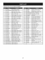
Craftsman
Snow Thrower
Model
247.883960
[]
/
i
/
3O
/
Craftsman
Snow Thrower
IViodel 247.883960
D =
O
684-04112C
HandleEngagementAssemblyRH
2.
738-04367
FlangeShoulderScrew
38.
710-04326
Screw,#8-16x 0.50
3.
731-04894D
LockPlate
39.
732-04219C
ClutchLock Spring
4.
684-04250
PivotRod
40.
712-3087
Wing Nut, 1/4-20
RubberBumper
41.
714-04040
BowTie CotterPin
5.
935-0199A
O
749-04191A-0691 UpperHandleLH
_ Screw,1/4-20x .500
42.
710-0262
CarriageBolt,5/16-18x 1.50
7.
731-04896B
ClutchLock Cam
43.
631-04133A
HandleClutchLockAssembly- LH
8.
712-04081A
ShoulderNut, 1/4-20
44.
684-04111B
HandleEngagementAssemblyLH
9.
710-0627
HexScrew,5/16-24x .750
45.
784-5594-0637
Cable Bracket
10.
731-06440A
LowerChute
46.
920-0284
Wing Knob
11.
720-0274
Grip
47.
712-04063
FlangeLock Nut,5/16-18
12.
710-1233
Screw,#10-24x 0.375
48.
731-06451
ChuteTilt CableGuide
13.
738-04348
ShoulderScrew,1/4-20
49.
711-04469A
ClevisPin
14.
710-04586
Screw,1/4-20x 1.625
50.
710-04484
Screw,5/16-18x 0.75
15.
749-04190A-0691 UpperHandleRH
51.
749-04138A-0691 LowerHandle
16.
710-0572
CarriageScrew,5/16-18x 2.25
52.
732-04238
TorsionSpring
17.
720-04039
Shift Knob
53.
936-0267
FiatWasher
18.
931-04187A
HandlePanel
54.
710-04022
Screw,M8-1.25
19.
731-05324
Lens
55.
936-0264
FiatWasher,.330x .630x .0635
914-0101
Cotter Pin
6.
L710-3069
20.
710-04071
CarriageBolt,5/16-18x 1.0
56.
21.
631-04653
HandleClutchLockAssembly- RH
57.
936-0159
FiatWasher,.349x .879x .063
22.
725-0157
CableTie
58.
731-06113
SteeringControl
23.
712-04064
FlangeLock Nut, 1/4-20
59.
738-04126
Pin,3/16
24.
732-0193
CompressionSpring
60.
716-04036
E-Ring
25.
790-00311A-0637 Shift Lever
61.
914-0145
Click Pin
26.
790-00248C-0637 PanelBracket
62.
732-04677
CableGuide
27.
738-04125
63.
747-05721
Chute Rod
28.
684-04310A-0637 ChuteSupportBracket
64.
731-08947
HandlePanelCover
29.
946-04396A
65.
790-00503
Chute Bracket
66.
925-05239
LEDLightSocket
ShoulderScrew
SpeedSelectorCable
30.
.736-04446
Flat Washer,.25x .630x .0515
31.
710-0895
Hi-LoScrew,1/4-15x .75
67.
725-05463
ElectricChuteHarness
32.
710-04370
HexScrew,1/4-20x 3.00
68.
710-04329
Screw,.159ODx .610
33.
L731-04427A
69.
710-0599
Screw (Forgroundwire)
34.
618-04932A
ElectricChuteGearboxAssembly
70.
731-08876
JoystickHousingCover
35.
710-04187
Hi-LoScrew,1/4-15x 0.5
--
753-08018¢
Chute Kit (Incl.Ref.#10 & 33)
36.
684-04404
ElectricChuteControlAssembly
LUpperChute
t- Availablefor warrantycoverageonly.Contacta Searsauthorized
serviceproviderfor details.
Continuedon next page
31
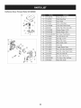
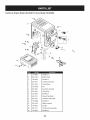
Craftsman
Snow Thrower
IViodel 247.883960
[]
D =
i
7
0
0
710-04373A
Screw,#12-16x .75
72.
711-05752
Shaft,WormDrive
73.
717-04973
Gear,Helical
74.
717-05019
Worm,2-Start Nylon
75.
731-07529A
Cover,Gear,ChuteControl
76.
936-0272
Wash.,Flat,.510x 1.00x .060
77.
741-04388A
Bearing,Flange,1.00ID
78.
741-04453A
Bearing,Flange,.50 ID
79.
790-00342B-0637 Brkt., Gear,ChuteRotation
80.
710-04509
Scr.,AB, #10-16x 1.25
81.
712-04063
Nut, Flgik.,5/16-18
82.
724-04145
Motor,Pitch,Chute
83.
724-04146
Motor,Rotate,Chute
84.
731-07868
Clip, Cable
85.
731-08795
Coupler,ElectricChute
86.
731-08845
Hsg., LH,4-Way,ChuteControl
87.
731-08846
Hsg., RH,4-Way,Chute Control
88.
731-1313C
Gde.,Cbl.,ChuteTilt
89.
938-0849
Scr.,Hex,5/16-18x .75
90.
946-04528B
Cbl.,Snow,4-Way,TallChute
91.
748-04297
Adpt.,Pitch,Chute
¸ • _
32
Craftsman
Engine
Model
483=SUB
For Snow Model
247.883960
m
D =
I!
II
1
710-04915
Bolt M6x12
2
951-11339
MufflerShield
3
710-04915
Bolt M6x12
4
951-10757
ThrottleControlKnob
5
951-11595
ControlPanel
7
731-05632
Key
8
951-10637
KeySwitchAssembly
9
951-11302
ChokeKnob
10
710-04914
Bolt M6xlO
11
951-11181
ExhaustPipe Shield
12
951-11321
CarburetorHeatShield
13
710-04968
Bolt M6x16
14
951-11338
MufflerAssembly
15
712-05015
Nut, M8
38
951-11311
ThrottleControlAssembly
39
710-04915
Bolt M6x12
33
Craftsman
Engine
Model
483-SUB
For Snow Model
247.883960
a
h
i
o
I
--134
m
x
m
m
D =
O
e
129
710-05392
StudM6-8x100
h
n/a
ThrottleShaft Cover
130
710-05056
StudM6-8x118
I
n/a
IdleJet Rivet
131
951-11315
CarburetorIntakeGasket
J
n/a
IdleJet Assembly
132
951-11316
CarburetorInsulator
k
n/a
IdleSpeedAdjustingScrew
133
951-11223
CarburetorGasket
I
n/a
PrimerPipe
134
951-14023A
CarburetorAssembly
m
751-11991
PrimerHose
135
951-10639A
PrimerAssembly
n
951-11906
PrimerHoseClamp
135
951-11824
PrimerBulb
0
n/a
CarburetorBody
136
951-11304
HeaterBox
P
n/a
FloatPin
137
951-11192
ChokeAssembly
q
n/a
EmulsionTube
138
736-04477
LockWasher
r
n/a
NickelPlatedBrassNeedleValve
139
712-05015
Nut M6
s
n/a
MainJet
147
951-12760A
CarburetorRebuildKit
t
n/a
NeedleValveSpring
(Inc.i,j,p,q,r,s,t,u,v,x,z)
U
n/a
Float
a
n/a
ChokeShaft
V
951-11970
FuelBowlGasket
b
736-04638
ChokeControlLeverWasher
W
n/a
FuelBowl
C
710-05469
FuelShutoffLeverScrew
X
951-11348
FuelBowlGasket
d
n/a
ChokePlate
Y
710-04945
FuelBowlMountingBolt
e
n/a
ThrottleShaft
Z
951-11349
FuelDrainPlugGasket
f
n/a
ThrottlePlate
aa
710-04938
FuelDrainPlug
g
n/a
Gasket
34
Craftsman
Engine
IViodel 483-SUB
For Snow IViodel 247.883960
4O
I
42
44
43
42
61
141
140
144- GasketKit-Complete
145-GasketKit-External
146-CompleteEngine
49
35
Craftsman
Engine
IViodel 483=SUB
m
For Snow IViodel 247.883960
m =
O
m
Q
D =
W
O
4O
951-11951
ConnectingRodAssembly
68
710-06063
Bolt M8x35
41
951-11952
Piston
69
710-04968
Bolt M6x16
42
951-11953
PistonPin Snap Ring
7O
951-11320
Oil TubeSupportBracket
43
951-11954
PistonPin
71
710-05349
Bolt M6x8
44
951-12579
PistonRingSet
73
951-11381
Oil FillTubeO-Ring
48
951-11956
GovernorGear/ShaftAssembly
74
951-12073
Oil FillTubeAssembly
49
951-11373
RadialBall Bearing
75
951-11904
DipstickO-Ring
5O
736-04453
Flat Washer
76
951-11971A
DipstickAssembly
51
714-04077
GovernorShaftClip
77
951-11341A
CrankcaseKit
52
951-11958
GovernorSeal
53
951-11365
GovernorArm Shaft
54
951-11342
CrankshaftKit
(Inc.40-44,48-68,77-81,
(Inc.49,54,55,65,81)
102,105,106,108,110,111,
55
951-10307
WoodruffKey
56
715-04102
DowelPin 9 X 12
78
951-11350
Oil DrainPipe
57
715-04092
DowelPin 7 X 14
79
736-04440
DrainPipeWasher 10X16X1.5
58
951-11959
CamshaftAssembly
8O
710-04906
Oil DrainPlug Bolt
59
951-11376
CrankcaseCoverGasket
81
951-11499
Oil Seal
60
736-04545
Washer
140
951-11968
BalanceGearAssembly
61
951-11283
Oil FillPlug Assembly
141
951-11969
Bearing
62
951-11577
O-Ring
143
951-10641
Oil DrainAsm
64
951-14220
CrankcaseCover
144
951-11330A
GasketKit- Complete
951-11340
CrankcaseCoverKit
(Inc.52,59,65,79,81,106,
(Inc.49,59,60,64-68)
108,125,131-133)
65
951-11375
Oil Seal
66
710-06061
Bolt M8x38
67
710-06062
Bolt M8x45
(Inc.49,52,77,81)
951-11328B
ShortBlockAssembly
125,131,132,140,141)
145
951-11331
GasketKit- External
(Inc.79,108,125,131-133)
146
36
952Z483-SUB
CompleteEngine
Craftsman
Engine
Model
483=SUB
For Snow Model
247.883960
142
123
123
123
145- GasketKit- I:xternal
123
146- Complete[ngine
37
Craftsman
Engine
IViodel 483-SUB
m
For Snow IViodel 247.883960
D =
O
m
0
D =
O
O
1CO 951-11337
ValveKit
116
951-12081
ExhaustLashCap
101
951-11337
ValveKit
117
951-11965
PushRodGuide
102
951-11962
Tappet
118
951-11981
RockerArmAssembly
103
951-11335
PushRodKit
119
710-04962
Bolt, Pivot
104
951-12555
CylinderHeadKit
120
951-11966
RockerArm
(Inc.106,110-112,125)
121
751-11123
AdjustingNut ,Valve
CylinderHeadAssembly
122
751-11124
PivotLockingNut
(Inc.100,101,104,106,108-112,
123
710-05054
ValveCoverBolt
114-122,125,129
-133)
124
951-11220
ValveCover
951-11967
ValveCoverGasket
951-11329B
105
715-04097
DowelPin
125
106
951-11963
CylinderHeadGasket
126a 731-07059
BreatherHose
SparkPlug/F6Rtc
126b 726-04101
BreatherHoseClamp
MufflerGasket
127
951-11317
CylinderBaffle
710-04915
BoltM6x12
107
108
951-10292
951-11212
109
710-04964
ExhaustStudM8x48.5
128
109
951-11207
MufflerStudAssembly
142
951-11333
ValveCoverKit
110
710-06064
BoltM10x1.25x87
144
951-11330A
GasketKit- Complete
111
710-06065
BoltM10x1.25x65
(Inc.52,59,65,79,81,106,
112
951-11964
IntakeValveSeal
108,125,131-133)
113
951-12077
IntakeValveSpringRetainer
114
951-12078
ValveSpring
115
951-12080
ExhaustValveSpring Retainer
145
951-11331
GasketKit- External
(Inc.79,108,125,131-133)
146
38
952Z483-SUB
CompleteEngine
Craftsman
Engine
Model 483-SUB
For Snow Model 247.883960
87
84
85
82
85
88
91
89
97
98
m
D =
m
O
D =
O
45
710-04965
Screw M4X 55
89
951-11313
CoolingFan
46
951-11196
ElectricStarter
90
951-11314
StarterCup
47
710-04967
Bolt M8x55
91
712-04220
FlywheelNut, M14x1.5
82
951-11305
IgnitionCoilAssembly
92
710-04968
Bolt M6x16
83
710-05350
IgnitionCoil Bolt
93
710-04915
Bolt M6x12
84
951-12553
AlternatorAssembly
95
951-11211
BlowerHousing
85
710-04969
Bolt M6x30
96
951-14223
Recoil StarterAssembly
86
710-04966
Bolt M6x8
97
736-04455
Flat Washer
87
951-11186
AlternatorWireClamp Bracket
98
710-04974
Bolt M6xlO
88
951-12556
Flywheel
39
Craftsman
Engine
IViodel 483=SUB
For Snow IViodel 247.883960
27
I
/.-25
%
26/
:}4 32
m
D =
16
951-12533
17
951-11933
18
m
O
m =
O
O
FuelCap Assembly
27
951-11336
FuelLine Kit
FuelLevelIndicator
28
951-11700
FuelHose Clamp
710-04970
BoltM8x20
29
710-04921
Bolt M8x14
19
750-05312
Bushing,Slot
30
951-11182
FuelTankMountingBracket
2O
750-05313
Bushing,Rnd
32
712-04212
FlangeNut M6
21
951-11201
FuelTankAssembly
33
710-04908
GovernorArm Bolt M6X21
22
951-11319
FuelTankShroud
34
951-11307
GovernorArm
23
951-11318
FuelTankMountingBracket
35
951-11306
GovernorSpring
24
951-11351
EngineShroud
36
951-11203
ThrottleReturnSpring
25
710-04968
BoltM6x16
37
951-11309
GovernorRod
26
736-04452
Bush
4O
Craftsman
Snow Thrower
IViodel 247.883960
777S32636
777125002
1001 IIIO-NV]10
"IVI1NVIA]
S,EIO/VEI3dO
QV]EI"_
"S3OV:IEInS
13AVEI9NO9NILVEI]d0
N3H_NOIlnV3VULX3
3sn'SEI3ONVIS,_9
lV39EIVHOSI(]
103EIIO
U3A3N'S31EIAPNI
$103r80 NMOEIItlQIOAVO1"1_
'3NIHOVW9NIOIAEI3S
EIO9NIOgO13NI1
3EIOd38O3ddOJ.S
3AVHSIUVd9NIAOW]IV lllNn $31QNVH
ONIH38NIVW3EI
ONV'3FIION3
d01S'SU3A31FI011110
39VgN3SIO
"_
"31fill0:I_EIVHOSIO
901ONAO/1001 .LAO-NV313
3Sn"_
"133:10NV
SONVFI
3].V±Ad_VNV0EI38AVEIOEI3il3dl_lH±IM
13VJ.NO0
"EI38flV
ONVEI31"13dl_l
9NIJ.VIOEI
WOEI:I
,WNWd3:Dt"L
777S32236
777D16350
ELECTRIC CHUTE
DIRECTIONAL CONTROL
777D16340
777122363
777D16338
777X43688
777122340
/
•
;" USEE85ORFUEL'
CONTAINING
MORE
THAN10% ETHANOL
777D18036
41
MTD CONSUMER GROUP INC (MTD), the California Air Resources Board (CARB)
and the United States Environment Protection Agency (U. S. EPA)
Emission
(Owner's
Control System Warranty
Defect Warranty
Statement
Rights and Obligations)
EMISSIONCONTROLSYSTEMCOVERAGEIS APPLICABLETOCERTIFIEDENGINESPURCHASEDIN CALIFORNIAIN 2005 ANDTHEREAFTER,WHICHARE USEDIN CALIFORNIA,ANDTO CERTIFIEDMODELYEAR2005 AND LATERENGINESWHICHARE PURCHASEDAND
USEDELSEWHEREIN THE UNITEDSTATES.
Californiaand elsewherein the UnitedStatesEmissionControlDefectsWarrantyCoverage
The CaliforniaAir ResourcesBoard(CARB),U. S. EPAand MTDare pleasedto explaintheemissionscontrol systemwarrantyon your modelyear
2006 and latersmalloff-roadengine.In California,new smalloff-roadenginesmustbe designed,builtand equippedto meet theStatesanti-smog
standards.Elsewherein the UnitedStates,newnon-road,spark-ignitionenginescertifiedfor model2005and later,mustmeet similarstandardsset
forth by the U. S. EPA.MTDmustwarrantythe emissioncontrolsystemon yourenginefor the periodof time listed below,providedtherehasbeen
no abuse,neglector impropermaintenanceof your smalloff-roadengine.
Youremissioncontrolsystemmay includepartssuch as the carburetor,fuel-injectionsystem,the ignitionsystem,and catalyticconverter,fueltanks,
fuel lines,fuel caps,valves,canisters,filters,vaporhoses,clamps,connectors,and otherassociatedemission-relatedcomponents.
Wherea warrantableconditionexists,MTDwill repairyoursmall off-roadengineat no cost to yourincludingdiagnosis,partsand labor.
MANUFACTURER'S WARRANTY COVERAGE:
This emissionscontrolsystemis warrantedfor two years.If anyemission-relatedpart on yourengine is defective,the part will be repairedor
replacedby MTD.
OWNER'S WARRANTY RESPONSIBILITIES:
As the smalloff-roadengineowner,youare responsibleforthe performanceof the requiredmaintenancelisted in your Owner'sManual.MTD
recommendsthat you retainall yourreceiptscoveringmaintenanceson yoursmalloff-roadengine,but MTDcan not denywarrantysolelyfor the
lack of receiptsor foryour failureto ensurethe performanceto all scheduledmaintenance.
As the smalloff-roadengineowner,youshouldhoweverbe awarethat MTDmaydenyyour warrantycoverageif yoursmall off-roadengine or part
hasfaileddue toabuse, neglect,impropermaintenanceor unapprovedmodifications.
Youare responsiblefor presentingyour smalloff-roadengineto an AuthorizedMTDServiceDealeras soonas a problemexists.Thewarranted
repairsshouldbe completedin a reasonableamountof time,notto exceed30 days.
If you haveanyquestionsregardingyourwarrantyrightsand responsibilities,you shouldcontacta MTDService Representativeat 1-800-800-7310
and addressis MTDCONSUMERGROUP,RO. Box361131,ClevelandOH,44136-0019.
DEFECTS WARRANTY REQUIREMENTS FOR 1995 AND LATER SMALL OFF-ROAD ENGINES:
This sectionappliesto 1995and later smalloff-roadengines.The warrantyperiodbeginson the datethe engineor equipmentis deliveredto an
ultimatepurchaser.
(a) GeneralEmissionsWarrantyCoverage_
MTDmustwarrantto the ultimatepurchaserand eachsubsequentpurchaserthat the engineis:
(1) Designed,built,and equippedsoas to conformwith all applicableregulationsadoptedby the Air ResourcesBoardpursuantto its authorityin
Chapters1 and 2,Part 5, Division26 of the Healthand SafetyCode; and
(2) Freefrom defectsin materialsand workmanshipthat causethe failureof a warrantedpart to be identicalin all materialrespectsto the partas
describedin theengine manufacturer'sapplicationfor certificationfora periodof two years.
.(b)The warrantyon emissions-relatedpartswill be interpretedas follows:
(1) Anywarrantedpart that is not scheduledfor replacementas requiredmaintenancein the writteninstructionsrequiredby Subsection(c)
mustbe warrantedfor the warrantyperioddefinedin Subsection(a)(2). If any such partfails duringthe periodof warrantycoverage,it mustbe
repairedor replacedby MTDaccordingto Subsection(4) below.Anysuch part repairedor replacedunder thewarrantymustbe warrantedfor
the remainingwarrantyperiod.
(2) Any warrantedpartthat is scheduledonlyfor regularinspectionin the writteninstructionsrequiredby Subsection(c) must be warrantedfor
thewarrantyperioddefinedin Subsection(a)(2).A statementin such writteninstructionsto the effectof "repairor replaceas necessary"will
not reducethe periodof warrantycoverage.Anysuch part repairedor replacedunderwarrantymustbe warrantedforthe remainingwarranty
period.
(3) Anywarrantedpartthat whichis scheduledfor replacementas requiredmaintenancein the writteninstructionsrequiredby Subsection(c)
mustbe warrantedfor the periodof time prior to the first scheduledreplacementpointforthat part. If the part fails priorto thefirst scheduled
replacement,the part mustbe repairedor replacedby MTDaccordingto Subsection(4) below.Any suchpart repairedor replacedunder
warrantymustbe warrantedfor the remainderof the period priorto the first scheduledreplacementpointfor the part.
(4) Repairor replacementof any warrantedpartunder thewarrantyprovisionsof this article mustbe performedat no chargeto the ownerat a
warrantystation.
(5) Notwithstandingthe provisionsof Subsection(4) above,warrantyservicesor repairsmustbe providedat all MTDdistributioncentersthat
are franchisedto servicethe subjectengines.
(6)Theowner
must
notbecharged
fordiagnostic
laborthatleads
tothedetermination
thatawarranted
partisinfactdefective,
provided
that
suchdiagnostic
workisperformed
atawarranty
station.
(7)Theengine
manufacturer
isliable
fordamages
toother
engine
components
proximately
caused
byafailure
under
warranty
ofanywarranted
part.
(8)Throughout
theengine's
warranty
period
defined
inSubsection
(a)(2),
MTD
willmaintain
a supply
ofwarranted
partssufficient
tomeet
the
expected
demand
forsuchparts.
(9)Anyreplacement
partmaybeused
intheperformance
ofanywarranty
maintenance
orrepairs
andmust
beprovided
without
charge
tothe
owner.
Suchusewillnotreduce
thewarranty
obligations
ofMTD.
(10)Add-on
ormodified
partsthatarenotexempted
bytheAirResources
Board
maynotbeused.
Theuseofanynon-exempted
add-on
or
modified
parts
shallbegrounds
fordisallowing
awarranty
claim
made
inaccordance
withthisarticle.
Theengine
manufacturer
shallnotbe
liable
under
thisarticle
towarrant
failures
ofwarranted
partscaused
bytheuseofnon-exempted
add-on
ormodified
part.
(c) MTDwill includea copy of the followingemissionwarrantyparts list with each newengine,usingthose portionsof the list applicableto the
e__&gine.
(1) FuelMeteringSystem
• Coldstart enrichmentsystem(soft choke)
,,Carburetor
andinternalparts
• Fuel Pump
• FuelTank
(2) Air InductionSystem
• Air cleaner
• Intakemanifold
(3) IgnitionSystem
• Sparkplug(s)
• MagnetoIgnitionSystem
(4) ExhaustSystem
Catalyticconverter
• SAI (Reedvalve)
(5) MiscellaneousItemsUsedin AboveSystem
Vacuum,temperature, position,time sensitivevalvesand switches
Connectorsand assemblies
(6) Evaporativecontrol
• Fuel Hosecertifiedfor ARBevaporativeemissionof 2006.
• Fuel HoseClamps
Tetheredfuel cap
Carboncanister
• Vaporlines
GD0C-100174Rev.B
Look For Relevant Emissions Durability Period and
Air index information On Your Engine Emissions Label
Engines that are certified to meet the California Air Resources Board (CARB) Tier 2 Emission Standards must
display information regarding the Emissions Durability Period and the Air Index. Sears Brands Management
Corporation makes this information available to the consumer on our emission labels.
The Emissions Durability Period describes the number of hours of actual running time for which the engine is
certified to be emissions compliant, assuming proper maintenance in accordance with the Operating & Maintenance Instructions. The following categories are used:
Moderate:
Engine is certified
to be emission compliant
for 125 hours of actual engine running time.
Intermediate:
Engine is certified
to be emission compliant
for 250 hours of actual engine running time.
Extended:
Engine is certified
to be emission compliant
for 500 hours of actual engine running time.
For example, a typical walk-behind lawn mower is used 20 to 25 hours per year. Therefore, the Emissions
Durability Period of an engine with an intermediate rating would equate to 10 to 12 years.
The Air index is a calculated number describing the relative level of emissions for a specific engine family. The
lower the Air Index, the cleaner the engine. This information is displayed in graphical form on the emissions label.
After
July 1,2000, Look For Emissions
Compliance
On Engine Emissions
Compliance
Label
Period
After July 1, 2000 certain Sears Brands Management Corporation engines will be certified to meet the United
States Environmental Protection Agency (USEPA) Phase 2 emission standards. For Phase 2 certified engines, the
Emissions Compliance Period referred to on the Emissions Compliance label indicates the number of operating
hours for which the engine has been shown to meet Federal emission requirements.
For engines less than 225 cc displacement,
For engines of 225 cc or more, Category
Category
C = 125 hours, B = 250 hours and A = 500 hours.
C = 250 hours, B = 500 hours and A = 1000 hours.
This is a generic representation of the emission label typically found on a certified engine.
FAMILY YBSXS.3192VA
274812
GDOC-100182
Rev.B
44
Congratulations
on making a smart purchase.
Your new Craftsman®
product is designed and
manufactured
for years of dependable operation. But like all products, it may require repair
from time to time. That's when having a Repair Protection Agreement can save you money and
aggravation.
Here's
[]
[]
[]
[]
[]
what
the
Repair
Protection
Agreement*
includes:
Expert service by our 10,000 professional repair specialists
Unlimited
service and no charge for parts and labor on all covered repairs
Product replacement
up to $1500 if your covered product can't be fixed
Discount
of 25% from regular price of service and related installed parts not covered by the
agreement; also, 25% off regular price of preventive maintenance check
Fast help by phone - we call it Rapid Resolution - phone support from a Sears representative.
Think of us as a "talking owner's manual."
Once you purchase the Repair Protection
to schedule service. You can call anytime
Agreement, a simple phone call is all that it takes for you
day or night, or schedule a service appointment
online.
The Repair Protection Agreement is a risk-free purchase. If you cancel for any reason during the
product warranty period, we will provide a full refund. Or, a prorated refund anytime after the
product warranty period expires. Purchase your Repair Protection Agreement today!
Some limitations
and exclusions
call 1=800=827=6655.
*Coverage
6665.
in Canada
Sears Installation
apply.
varies on some
For prices and additional
items. For full details
information
call Sears Canada
in the U.S.A.
at 1=800=361=
Service
For Sears professional
installation
of home appliances, garage door openers,
other major home items, in the U.S.A. or Canada call 1=800=4=MY=HOME®.
45
water heaters,
and
Declaraci6n de garantia ............................ Pagina
Practicas operaci6n seguras ..................... Pagina
Montaje ......................................................
Pagina
Operaci6n ..................................................
Pagina
Servicio y Mantenimiento .......................... Pagina
Almacenamiento fuera de temporada ....... Pagina
46
47
51
57
62
69
Soluci6n
Acuerdo
Lista de
NOmero
GARANTJA COMPLETA CRAFTSMAN
de problemas .............................. Pagina 70
de protecci6n para reparaciones .... Pagina 75
piezas ........................................... Pagina 26
de servicio ................................... Cubierta
posterior
POR DOS ANOS
PORDOSANOSa partir de la fechade la cornpra,este productoest_ garantizadopor defectosen los rnaterialesy la rnanode obra.
Los productosdefectuososser&nreparadossin costoo reemplazadossin costosi la reparaci6nno est&disponible.
GARANTJA DE POR VlDA LIMITADA ADIClONAL en la tolva de UPPER y LOWER
PARASIEMPREY CUANDOSE UTILIZApor el propietariooriginaldespu6sdel segundoaSodesdela fecha de compra,el conductosuperiore
inferiorde estequitanievesest_n garantizadoscontracualquierdefectode rnaterialeso rnanode obra debe serverificadopor un proveedorde
servicioautorizadoSears.Con el cornprobantede cornpra,usted recibir_una rarnpanuevade forrnagratuita.Ustedes responsablepor el costo
de la rnanode obra de instalaci6ny otros gastosocasionadosparaverificarel defecto.
Paraobtener inforrnaci6nsobreel alcance de la garantiay solicitarla reparaci6no el reernplazo,visiteel sitioWeb: www.craftsrnan.corn
Esta garantiacubre0NICAMENTElos defectos en los materiales yen la rnano de obra. Esta garantiaNOcubre:
•
Elernentosno renovablesque puedendesgastarsepor el uso normal,duranteel plazode la garantia,incluyendo
entreotros,las barrenas,
las paletasde las barrenas,los cortadoresde desplazarniento,laszapatasantideslizantes,la placade raspado,lospasadoresde cuchilla,
la bujia,el filtro de aire,las correasy el filtro de aceite.
•
Serviciosde rnantenirnientoestandar,carnbiosde aceiteo afinaci6n.
•
Carnbiode neurnAticoso reparacionespor pinchadurascon objetosexternoscornoclavos,espinas,toconeso vidrios.
•
Reernplazoo reparaci6nde neurn_ticoso ruedascornoresultadodel desgastenormal,un accidente,o funcionarniento
o rnantenirnientoincorrectos.
•
•
•
•
Reparacionesrequeridascornoresultadodel uso inadecuado
por partedel operador,incluyendo
entreotros el da_oocasionadopor objetos
que irnpactan
la rnaquinay que tuercenel bastidor,el eje de la barrena,etc., o debido a que el motorfueaceleradoen exceso.
Reparacionesnecesariasdebidoa negligenciadel operador,incluyendo
entre otros,da_osrnec_nicoy el6ctricoocasionadopor
un almacenarnientono apropiado,fallapor el uso de aceitede gradoy/o cantidadno apropiadoso falla por no dar rnantenirniento
al equipo de acuerdocon las instrucciones
contenidasen el manualdel operador.
Lirnpiezao reparacionesdel motor(sistemade combustible)debidasa combustibleque se deterrninaestAcontarninadou oxidado(viejo).
En general,el combustibledebe utilizarseen un periodono mayorde 30 dias a partirde su adquisici6n.
El deterioroy desgastenormalde losacabadosexteriores,o reernplazode la etiquetadel producto.
La presentegaranfiase anula si se utilizaeste productoalgunavez para prestarservicioscornercialeso si se Ioalquilaa otra persona.
Estagaranfiale otorgaderechoslegalesespecificos,pero ustedpodria gozarde otros derechosen raz6nde su lugarde residencia.
Sears Brands
Management
Corporation,
Hoffman
Estates,
IL 60179
37 onzas
N_mero de modelo ..........................................................
N_mero de serie ..............................................................
Aprox. 5 cuartos
Fechade compra .............................................................
F6RTC (951-10292)
.020" a .030"
Registrearriba el nOrnerodel rnodelo,el nOrnerode seriey la fecha
de cornpra
Tipode aceitedel motor:
Capacidadde aceitedel motor:
Capacidadde combustible:
SAE 5W-30
Bujfas:
Separaci6nde lasbujias:
© Sears Brands,LLC
46
Esta rn_.quina
rue construidapara seroperadade acuerdocon
las reglasde seguridadcontenidasen este manual.AI igualque
concualquiertipo de equipo rnotorizado,un descuidoo error por
partedel operadorpuedeproducirlesionesgraves.Esta rn_.quina
es capazde arnputarrnanosy piesy de arrojarobjetoscon gran
fuerza.Deno respetarlas instruccionesde seguridadsiguientesse
puedenproducirlesionesgraveso la rnuerte.
La presenciade este sfrnboloindicaque setrata de instrucciones
irnportantesde seguridadque se deben respetarpara evitar
poner en peligrosu seguridadpersonaly/o materialy la de otras
personas.Lea y siga todaslas instruccionesde este manualantes
de poneren funcionarnientoesta rn_.quina.Si no respetaestas
instruccionespodrfaprovocarlesionespersonales.Cuandoveaeste
sfrnbolo,i presteatenci6na la advertencia!
PROPOSICION
65 DE CALIFORNIA
Su responsabilidad--Restrinja
el usode esta rn_.quina
rnotorizadaalas personasque lean,cornprendany respetenlas
advertenciase instruccionesque aparecenen este manualyen la
rn_.quina.
El escapedel motorde este producto,algunosde suscornponentes
y algunoscornponentesdel vehfculocontieneno liberan sustancias
qufrnicasque el estado de Californiaconsideraque puedenproducir
c_.ncer,defectosde nacirnientou otros problernasreproductivos.
iGUARDE
ESTAS
INSTRUCCIONES!
CAPACITACI6N
PR E PA RATIVO S
•
Inspeccionerninuciosarnenteel _.readondeutilizar_,el equipo.Saque
todos los felpudos,peri6dicos,trineos,tablas,cablesy otros objetos
extra_oscon los que podrfatropezaro que podrfanser arrojadospor
la barrena/irnpulsor.
•
Paraprotegerselosojos utilice siernpreanteojoso antiparras
de seguridadrnientrasopera la rn_.quina
o rnientrasla ajusta
o repara.Losobjetosarrojadosque rebotanpuedenproducir
lesionesocularesgraves.
•
•
•
•
•
•
•
Lea,entienday curnplatodas las instruccionesincluidasen
la rn_.quina
y en los rnanualesantes de rnontarlay utiNzarla.
Guardeeste manualen un lugarseguroparaconsultasfuturasy
peri6dicas,asf cornopara solicitarrepuestos.
Lea el Manualdel Operadory sigatodas las advertenciase
instrucciones
de seguridad.Elfracasode hacerasf puedecausar
la heridaseriaal operadory/o personaspresentes.
Farniliarfcesecontodos los controlesy con el usoadecuado
de los rnisrnos.Sepa c6rnodetenerla rn_.quinay desactivarlos
controlesr_.pidarnente.
No perrnitanuncaque los ni_osrnenoresde 14a_osutilicen
esta rn_.quina.Los ni_osde 14a_osen adelantedeben leer y
entenderlas instruccionesde operaci6ny norrnasde seguridad
contenidasen este manual,yen la rn_.quina
ydebenser entrenadosy supervisadospor un adulto.
Nuncaperrnitaque los adultosoperenesta rn_.quinasin recibir
antesla instrucci6napropiada.
Losobjetosarrojadospor la rn_.quinapuedenproducirlesiones
graves.Planifiqueel patr6nen el que va air arrojandonievepara
evitarque la descargade materialse realicehacialos carninos,
los observadores,etc.
Mantengaa losobservadores,ayudantes,rnascotasy ni_ospor
Io rnenosa 75 piesde la rn_.quina
rnientrasla rnisrnaest,.en
funcionarniento.Detengala rn_.quinasi alguienseacerca.
•
•
•
•
Sea precavidopara evitarpatinarseo caerseespecialrnente
cuandoopera la rn_.quina
en reversa.
4.7
Noopere la rn_.quinasin la vestirnentaadecuadaparaestar al
aire libre en invierno.No utilicealhajas,bufandaslargasu otras
prendassueltasque podrfanenredarseen las partes rn6viles.
UtiNceun calzadoespecialpara superficiesresbaladizas.
Useun prolongadory un tornacorrientede tres cables con
conexi6na tierraparatodas las rn_.quinascon rnotoresde
encendidoel_ctrico.
Ajuste la alturade la caja del tornacorrientepara Nrnpiarla grava
o las superficiescon piedrastrituradas.
Desengranetodaslas palancasde controlantesde arrancarel
motor.
•
Nuncaintenterealizarajustesrnientrasel motorest,. en rnarcha
exceptoen los casosespecfficarnenterecornendadosen el
manualdel operador.
•
Dejeque el motor y la rn_.quinase adaptena la ternperatura
exteriorantesde cornenzara sacarla nieve.
Manejo seguro de la gasolina
Paraevitar lesionespersonales0 daSosrnaterialestengarnucho
cuidadocuandotrabajecon gasolina.La gasolinaes surnarnente
inflarnabley sus vaporespuedencausarexplosiones.Si se derrarna
gasolinaencirna0 sobrela ropa se puedelesionargravernenteya que
se puedeincendiar. L&vesela piel y c&rnbiesede ropade inrnediato.
•
•
•
Utilices610los recipientespara gasolinaautorizados.
Apaguetodos los cigarrillos,cigarros,pipasy otras fuentesde
cornbusfi6n.
•
•
Noutilice la rn_.quina
bajo la influenciadel alcoholo las drogas.
El silenciadory el motorse calientany puedencausarquernaduras. Nolos toque. Mantengaa los niSosalejados.
•
•
Nuncacarguecombustibleen la rn&quinaen un espaciocerrado.
Nuncasaquela tapadel combustibleni agreguecombustible
rnientrasel motorest&caliente0 en rnarcha.
•
•
Dejeque el motorse enfriepor I0 rnenosdos rninutosantesde
volvera cargarcombustible.
Nuncallene en excesoel dep6sitode combustible.Lleneel
tanquea no rn&sde 1/2pulgadapor debajode la basedel cuello
de Ilenadodejandoespaciopara la dilataci6ndeIcombustible.
Vuelvaa colocarla tapade la gasoiinay aj_stelabien.
•
Sea surnarnenteprecavidocuandoopere la rn_.quinasobreuna
superficiecon gravao cuandola cruce.Mant_ngasealerta por si
se presentanpeligrosocultoso tr_.nsito.
Tengacuidadocuandocarnbiede direcci6no cuandoopere
la rn_.quinaen pendientes.Nouse la rn_.quina
en pendientes
pronunciadas.
•
•
•
•
•
•
•
•
•
•
Lirnpieel combustibleque se hayaderrarnadosobreel motory el
equipo.Trasladela rn&quinaa otra zona. Espere5 rninutosantes
de encenderel motor.
•
•
Nuncaalrnacenela rn&quina0 el recipientede combustibleen
un espaciocerradodonde hayafuego,chispas0 luz piloto(por
ejernplo,hornos,calentadoresde agua,calefactores,secadores
de ropa,etc.).
•
Dejeque la rn_.quinase enfriepor Io rnenos5 rninutosantesde
guardarla.
NuncaIlenelos recipientesen el interiorde un vehiculoo carni6n
o caja de rernolquecon recubrirnientospl_.sticos.Coloque
siernprelos recipientesen el pisoy lejosdel vehiculoantesde
Ilenarlos.
•
•
•
Si es posible,retireel equipoa gasolinadel carni6no rernolque
y II_neloen el suelo.Si esto no es posible,Ileneel equipoen un
rernolquecon contenedorport_.til,en vez de desdeuna boquilla
dispensadorade gasolina.
Mantengala boquilladispensadoraen contactocon el hordedel
dep6sitode combustibleo con la aberturadel recipienteen todo
rnornento,hastaterrninarla carga. No utiliceun dispositivode
apertura/cierrede boquilla.
•
FUNCIONANIIENTO
•
No pongalas rnanoso los piescerca de las piezasrotatorias,
en la cajade la barrena/ irnpulsoro en el rnontajedel canalde
descarga.Hacercontactocon piezasgiratoriaspuederesultaren
la arnputaci6nde rnanoso pies.
•
La palancade controlde la barrena/ irnpulsores un dispositivo
de seguridad.Nuncaevite su funcionarniento.De hacerlola
operaci6nde la rn_.quinaes riesgosay puedeocasionarlesiones.
Las palancasde control debenfuncionarbien en arnbasdireccionesy regresarautorn_.ticarnente
a la posici6nde desengrane
cuandose lassuelta.
•
•
48
•
Nuncaoperela rn_.quinasi falta un rnontajedel canalo si el
rnisrnoest,. daSado.Mantengatodos losdispositivosde seguridad en su lugaryen funcionarniento.
Nuncaenciendael motor en espacioscerradoso en una zona
con pocaventilaci6n.El escapedel motorcontienernon6xidode
carbono,un gas inodoroy letal.
Planifiqueel patr6nen el que va air arrojandonieveparaevitar
que la descargade materialse produzcahacialas ventanas,
las paredes,losautorn6viles,etc.y evitarasi posiblesdaSos
rnaterialeso lesionesproducidaspor los rebotes.
Nuncadirija la descargahacialos niSos,los observadoreso las
rnascotasni deje que nadiese pare delantede la rn_.quina.
Nosobrecarguela capacidadde la rn_.quina
tratandode sacarla
nievernuyr_.pidarnente.
Nuncaopereesta rn_.quinasin buenavisibilidado ilurninaci6n.
Siernpredebe estar segurode que est,. bien afirrnadoy sujetandofirrnernentelas rnanijas.Carnine,nuncacorra.
Corte la corrientea la barrena/ irnpulsorcuandotransportela
rn_.quinao cuandola rnisrnano est,. en uso.
Nuncaoperela rn_.quinaa alta velocidadde desplazarniento
sobresuperficiesresbaladizas.Mirehaciaabajoy haciaatr_.sy
tengacuidadocuandovaya rnarchaatr_.s.
Si la rn_.quinacornenzaraa vibrarde rnaneraanorrnal,detengael
motor,desconecteel cablede la bujia y p6ngalade rnaneraque
haga rnasacontra el motor.Inspeccionela rn_.quinarninuciosarnenteparaver si est,. daSada.Reparetodos los daSosantesde
encendery operar la rn_.quina.
Desengranetodas las palancasde controly detengael motor
antes de dejar la posici6nde operaci6n(detr_.sde las rnanijas).
Esperea que la barrena/ irnpulsorse detengapor cornpleto
antes de destaparel rnontajedel canalo realizarajustese
inspecciones.
Nuncapongalas rnanosen las aberturasde descargao de
recolecci6n.Utilicesiernprela herrarnientade lirnpiezaque se
adjuntaparadestaparla aberturade descarga.Nodestapeel
rnontajedel canal rnientrasel motorest,. en funcionarniento.
Antesde destaparlo,apagueel motory perrnanezcadetr_.sde las
rnanijashastaque todaslas partes rn6vilesse hayandetenido.
Uses61ounionesy accesoriosaprobadospot el fabricante(por
ejernplo,pesaspara las ruedas,cadenaspara los neurn_.ticos,
cabinas,etc.). Paraobtenerrn_.sinforrnaci6nacercade estos
ternas,Ilarneal 1-800-469-4663.
•
•
•
Paraencenderel motor,jale de la cuerdalentarnentehasta que
sienta resistencia,luegojale r_.pidarnente.
El replieguer_.pidode
la cuerdade arranque(tensi6nde retroceso)le jalar_,la rnanoy
el brazohaciael motor rn_.sr_.pidode Io que usted puedesoltar.
El resultadopuedenserhuesosrotos,fracturas,hernatornaso
esguinces.
Si se presentansituacionesque no est_.nprevistasen este
manual,seacuidadosoy use el sentidocornOn.
•
•
•
•
•
•
SegOnla Cornisi6nde Seguridadde Productosparael Consurnidor de los EstadosUnidos(CPSC)y la Agenciade Protecci6n
Arnbientalde los EstadosUnidos(EPA),este productotieneuna
vida Qtilmediade siete (7) a_os, 6 60 horasde funcionarniento.
AI finalizarla vida Otilmedia,adquierauna rn_.quinanuevao
hagainspeccionaranualrnente_sta por un distribuidorde servicio
autorizadopara cerciorarsede que todoslos sisternasrnec_.nicos
y de seguridadfuncionancorrectarnentey no tienenexcesivo
desgaste.Si no Iohace, puedenproducirseaccidentes,lesiones
o rnuerte
•
Nuncaalrnacenela rn_.quina
o el recipientede combustibleen un
espaciocerradodondehayafuego,chispaso luz pilotocornopor
ejernplo,calentadoresde agua,hornos,secadoresde ropa,etc.
•
Consultesiernpreel manualdel operadorparaobtener
instruccionesadecuadaspara el alrnacenarnientofuerade
ternporadaVerifique
frecuenternentela Ifneade combustible,el
tanque,el tap6n,y losaccesoriosbuscandorajaduraso perdidas.
Reernplacede ser necesario.
Nod_ arranqueal motorsi no est,. la bujia de encendido.
Para pedirrepuestoso serviciohorariopara este producto,Ilarne
a 1-800-469-4663.
MANTENIMIENTO
•
•
Y ALMACENAMIENTO
Nuncaalterelos dispositivosde seguridad.Controleperi6dicarnenteque funcionencorrectarnente.Rernitasealas secciones
de mantenirnientoy ajustede este manual.
Antesde realizarla lirnpieza,repararo revisarla rn_.quina,
desengranetodas laspalancasde controly detengael motor.
Esperea que la barrena/ irnpulsorse detengapor cornpleto.
Desconecteel cablede la bujfay p6ngalohaciendornasacontra
el motorpara evitarque se enciendaaccidentalrnente.
Controlefrecuenternenteque todos lospernosy tornillosest_n
bien ajustadosparacornprobarque la rn_.quinase encuentra
en condicionessegurasde funcionarniento.Adern_.s,haga una
inspecci6nvisual de la rn_.quinapara verificarsi est,. da_ada.
No carnbiela configuraci6ndel reguladordel motorni acelere
dernasiadoel rnisrno.El reguladordel motorcontrolala velocidad
rn_.xirnasegurade funcionarnientodel motor.
•
NO MODIFIQUE
EL MOTOR
Paraevitarlesionesgraveso la rnuerte,no rnodifiqueel motorbajo
ningunacircunstancia.Si carnbiala configuraci6ndel reguladorel
motorpuededescontrolarsey operara velocidadesinseguras.Nunca
carnbiela configuraci6nde f_.bricadel reguladordel motor.
AVISO REFERIDO
A EMISIONES
Losrnotoresque est&ncertificadosy curnplencon las regulaciones
Las placasde raspadoy las zapatasantideslizantesque se
de ernisionesfederalesEPAy de Californiapara SORE(Equipos
usancon la rn_.quina
quitanievese desgastany se da_an.
peque_ostodoterreno)est_.ncertificadosparaoperarcon gasolina
Para protegersu seguridad,verifiquefrecuenternentetodos los
cornOnsinplornoy puedenincluirlossiguientessisternasde control
cornponentesy reernpl_.celos
s61ocon partesde los fabricantes
de ernisiones:Modificaci6nde motor(EM) y catalizadorde tres vias
de equiposoriginales(OEM). iEI usode piezasque no curnplen
(TWO)si est_.nequipadosde esa rnanera.
con lasespecificacionesdel equipooriginalpuede resultaren
GUARDACHISPAS
rendirnientoinadecuadoadern_.sde poneren riesgola seguridad!
Reviselas palancasde controlperi6dicarnentepara verificar
que engraneny desengranenadecuadarnentey ajOstelossi es
Esta rn&quinaest,. equipadacon un motorde cornbusti6ninternay
necesario.Consultela secci6nde ajustesde este manualdel
no debe ser utilizadaen o cercade un terrenoagrestecubiertopor
operadorpara obtenerinstrucciones.
bosque,rnalezaso hierba exceptosi el sisternade escapedel motor
Mantengao reernplacelasetiquetasde seguridade instrucciones est,. equipadocon un arnortiguadorde chispasque curnplaconlas
leyeslocaleso estatalescorrespondientes,en caso de haberlas.
segQnseanecesario.
•
Respetelas norrnasreferentesa la disposici6ncorrectay las
reglarnentacionessobregasolina,aceite,etc. para protegerel
medic arnbiente.
•
Antesde alrnacenarla rn_.quinaenci_ndalaunosrninutospara
sacarla nieveque hayaquedadoen la rnisrnay paraevitarasi
que se congelela barrena/irnpulsor.
Si se utilizaun arnortiguadorde chispasel operadorIo debe rnantener
en condicionesde usoadecuadas.Enel Estadode Californialas
rnedidasanteriorrnenternencionadassonexigidaspor ley (Arficulo
4442 del C6digode RecursosPOblicosde California).Es posible
que existanleyessirnilaresen otros estados.Lasleyesfederalesse
aplicanen territoriosfederales.
Puedeconseguirel arnortiguadorde chispasparael silenciadora
travesde sudistribuidorautorizadode rnotoreso poni_ndoseen
contactocon el departarnentode servicios.
49
SiMBOLOS
DE SEGURIDAD
Esta p_ginadescribelossirnbolosy figurasde seguridadinternacionalesque puedenapareceren este producto.Lea el manualdel operador
)araobtenerla inforrnaci6nterrninadasobreseguridad,reunirse,operaci6ny rnantenimientoy reparaci6n.
i
LEA ELMANUAL DELOPERADOR(S)
Lea,entienda, y siga todas lasinstrucciones en el manual (es)antes de intentar reunirse y funcionar.
i
LA ADVERTENCIA --
PLATOS ROTATORIOS
Guarde manos de entrada y aperturas
de la descarga mientras
la m_iquina corre. Alli ellos hacen para
girar platos dentro.
LA ADVERTENCIA-
LAMINAS ROTATIVAS
Guarde manos de entrada y aperturas
dentro.
de descarga mientras
la m_iquina corre. Alli hacen girar I_iminas
LA ADVERTENCIA -- TALADRO ROTATIVO
No ponga manos o pies cerca del giro de partes, en el alojamiento
tolva. Contacto
con las partes rotativas
OBJETOS LANZADOS
Esta m_iquina
puede amputar
de taladro/aspa
o asamblea
de
manos y pies.
POR ADVERTENClA
puede recoger y lanzar objetos
que pueden
causar la herida personal
seria.
GASOLINA DE ADVERTENClA ESINFLAMABLE
Permita que el motor se enfrie al menos dos minutos
ADVERTENCIA
--
MONOXIDO
Nunca dirijas un motor dentro
contienen
el mon6xido
antes del reabastecimiento
DE CARBONO
o en un _irea mal ventilada.
de carbono, un gas inodoro
Los gases de combusti6n
y mortal.
ADVERTENCIA -- ELECTROCHOQUE
No use eljuez de salida el6ctrico del motor en la Iluvia.
5O
de combustible.
de motor
NOTA:Las referenciasal lado derechoo y ciertosde la rn_.quina
quitanievese deterrninandesdela parteposteriorde la unidaden
posici6nde operaci6n(perrnaneciendodirectarnentedetr_.sde la
rn_.quinaquitanieve,rnirandohaciael panelde la rnanija).
EXTRACCION
1.
DE LA UNIDAD
DE LA CAJA
2.
Corte lasesquinasde la cajade cart6ny exti_ndalaen el piso
Quitey descartetodoslos insertosde ernpaque.
Saquela rn_.quinaquitanievede la caja.
3.
AsegQresede vaciarcornpletarnentela cajaantesde tirarla.
MONTAJE
1.
Observeel _.reainferiortraserade la rn_.quina
quitanievepara
asegurarsede que arnboscablesest_n alineadoscon las guias
rotatoriasantes de girar la rnanijahacia arriba.
a.
Coloquela palancade carnbiosen la posici6nde avance(F)
6.
b.
2.
Tirehaciaarriba y haciaatr_.sde la rnanijasuperior,tal y
cornose rnuestraen la figura1.Cuandoustedlevantael
mangohaciaarriba,asegQreseque arnbosfinalesdel cable
de centro soncolocadoscorrectarnenteen lossoportes.Vea
la figura2. Alinee la rnanijasuperiorcon la rnanijainferior.
c. Aprietelas perillasrnanualesque sujetanla rnanijasuperior
a la rnanijainferior.Retirey descartetodos las bandasde
pl_.stico,si Las hubiera.0nicarnentese utilizanpara el
ernpaque.
Retireel pasadorde chaveta,la tuerca de rnariposay el tornillo
hexagonaldel cabezalde controldel canal,y el pasadorde
horquillay el pasadorde chavetacon uni6ncurva de la rn_nsula
de soportedel canal. Vea la figura3.
Figura2
Ca'bezal de
Control
del
Canal
Misrno
Figura3
Figura1
3. Inserte
lavarilla
hexagonal
dentro
delcabezal
decontrol
del
canal.
Empuje
lavarilla
tanlejosdentro
delcabezal
decontrol
delcanal
como
seaposible,
manteniendo
elorificio
enlavarilla
hexagonal
seSalando
hacia
arriba.
VealaFigura
4.
4. Lugar
enlatolvatolvadebase
ygarantizar
lavarilla
hexagonal
est,.situado
bajoelasadelpanel.
Lacabeza
seguro
control
del
canal
desoporte
desoporte
delcanal
conelpasador
dehorquilla
ypajarita
pasador
extrafdo
enelpaso1.Vealafigura
5.
5. Finalizar
lacabeza
deasegurar
elcontrol
delconducto
conla
instalaci6n
detornillo
hexagonal
ytuerca
demariposa.
Veala
figura
6.
f
Figura5
f
/!
//
/
/
/
Figura4
Figura6
52
6.
7.
Insertarel otroextrernode la varillade controldel canal en el
acopladorpor debajodel panel de asa. AsegQresede alinearla
parteplana de la varillay el extrernopianodel acoplador.Puede
que tengaque girar la barra en tornoa estasIfneashasta dos
superficies.Consultela figura7.
Ernpujela barrade controldel canal haciael panel de control
hastaque el agujeroen las Ifneasde varillacon el agujerodel
medic en la entradade controldel canale insertela chaveta.Vet
la figura8.
NOTA:Existeun agujerode referenciaproporcionadoen el extrerno
posteriorde la barrade control paraayudara sabercuandolos
agujerossonverticales.
NOTA:El agujerorn_.salejadode la cabezade control tolvase utiliza
para Iograruna mayorirnplicaci6nde la varillade controldel canalen
el engranajede pifi6n si es necesario.Consultela secci6nMantenirnientoy Ajustespara el ajustede varillade controldel canal.
El agujerorn_.scercanoa la cabezade controltolva seutiliza parael
rnovirnientomanualdel rnontajedel canalsi es necesario.Consultela
secci6nde los controlesy caracterfsticas.
8. Controleque todos los cablesest_nadecuadarnentedirigidosa
travesde la guia de cablesde la partesuperiordel motor.Veala
figura9.
Figura8
NOTA:Pararn_.ssuavefuncionarniento,loscables debenestar a la
izquierdade la varillahexagonal.
9. El prolongadorpara el arrancadorel_ctricose ajustarnediante
una uni6nde cablea la parteposteriorde la caja de la barrena
para el ernbarque.Corte la uni6n de cabley refirelaantes de
operarla rn_.quinaquitanieve.
f
Figura 9
J
Figura7
53
CONFIGURACI6N
Pasador
de cuchilla
En el panelde instrurnentos
de pl_sticohay orificiospara el almacenarnientoconvenientedel pasadorde cuchilla.Veala figura10.
Consultela secionde servicioy rnantenirnientopararn_.sinforrnaci6n
en cuantoel reernplazodel pasadorde cuchiNa.
Herramienta
de Limpieza
del Canal
Hay una herrarnientade Nrnpiezadel canal iajustadaa la parte
superiorde la caja de la barrenacon un pasadorde ensarnblado.Vea
la figura 11.La herrarnientaest,. dise_adaparaNrnpiarel hieloy la
nievedel rnontajede un canal.Este productose sujeta rnedianteuna
uni6nde cableen la f_.brica.Corte la uni6n de cableantes de operar
la rn_.quina
quitanieve.
Nuncausesus rnanospara liberar un rnontajede canaltapado.
Apagueel motory perrnanezcadetr_.sde lasrnanijashasta que todas
las partes rn6vilesse hayandetenidoantesde utiNzarla herrarnienta
de NrnpiezaparaNrnpiarel rnontajedel canal.
.J
Figura10
f
Herramienta de
Limpieza del Canal
J
Figura11
54
Cortadores
de desplazamiento
1.
Retirelosdostornillosy pornosde rnariposade seguridadque
sujetancadacortadorde desplazarnientode nievey refirelosde
los ladosde la cajade la barrena.
2.
Gire loscortadoresde desplazarnientode nievey posici6nelos
segQnse rnuestraen la Figura12 haciael exteriorde la caja de
[a barrena.
3.
Acopleloscortadoresde desplazarnientode nievecon los
tornillosy los pornosde rnariposade seguridadque se retiraron
antes.Vea [a Figura13.
Presi6n
f
de nieve
/
' i
\
de los neumaticos
Losneurn_.ticossondernasiadoinfladospara prop6sitosde envio.
Revise[a presi6nde los neurn_.ticos
antes de [a nievelanzador.Se
refierena [a paredlateralde[ neurn_.tico
para e[ fabricantede neurn_.ticos recornendadopsi y desinfiar(o inflar)los neurn_.ticos,
segQnsea
necesario.
/
Figura12
Bajoningunacircunstanciano excedandel fabricanterecornienda
psi. La igualdadde la presi6nde los neurn_.ticos
deben rnantenerse
en todomornento.Cuando[a presi6nexcesivapuedecausarasientos
bolasneurn_.tico
/ liantade rnontajepara reventarcon[a fuerza
suficienteparacausar un daSograve.Se refierena losfiancosde los
neurn_.ticos
de la presi6nrecornendada.
NOTA:La igualdadde la presi6nde los neurn_.ticos
debe set mantenidaen todo rnornentopara los efectosde [a performance.
AJUSTES
Zapatas
antideslizantes
Laszapatasantideslizantesde la rn_.quinaquitanieveseajustanpara
arribaen f_.bricapara el envio. Si Io desea,puedeajustarlashacia
abajoantes de hacerfuncionarla rn_.quinaquitanieve.
Nose recorniendaque opereesta rn_.quinaquitanievesobregrava,
ya que es posibleque la rn_.quina
quitanievetome la gravasueltay
la barrenala expulse,Io cual podriacausarlesionespersonaleso
daSarla rn_.quina
quitanieve.
Figura13
•
•
Si deseaquitarnieveal rasdel suelo,elevern_.slaszapatas
antideslizantesen la cajade la barrena.
Use las posicionesmediao baja cuandola superficieque desee
lirnpiarseadespareja,cornoun carninode grava.
NOTA:Si tieneque usarla rn_.quina
quitanievesobregrava,rnantenga
la zapataantideslizanteen la posici6nrn_.selevadapara Iograruna
separaci6nrn_.xirnaentreel pisoy la placade raspado.
55
Paraajustar laszapatasantideslizantes:
1. Aflojelas cuatrostuercashexagonales(dosen cada lado)y los
pernosdel carro. Muevalas zapatasantideslizantesa la posici6n
deseada.Vea la figura 14.
2.
3.
f
Superficie
lisa
Cornpruebeque toda la superficieinferiorde laszapatas
antideslizantesest_contra el sueloparaevitar un desgaste
desparejode los rnisrnos.
Vuelvaa ajustarbien lastuercasy lospernos.
Prueba
de control
de la barrena
Antesde operarsu rn_.quinaquitanieve,lea atentarnentey curnplato-I
das las instruccionesque aparecena continuaci6n.Realicetodos losI
ajustesparaverificarque la rn_.quinaest,. operandocon seguridady I
correctarnente.
]
Superficie
clesigual
Cornpruebeel ajustedel controlde la barrenade la siguienteforrna:
1.
2.
3.
4.
5.
6.
El controlde la barrenaseencuentraen el mangoizquierdo.
Consultela Figura11el recuadro.Cuandose sueltael controlde
la barrenay est,.en posici6ndesengranadaarriba,el cable debe
tenerrnuypocojuego.NOdebe estar tenso.
En un _.reabien ventilada,arranqueel motorde la rn_.quina
quitanievesegQnse indicaanteriorrnenteen esta rnisrnasecci6n.
Paradoen la posici6ndel operador(detr_.sde la rn_.quina
quitanieve),engranela barrena.
Dejela barrenaengranadaduranteaproxirnadarnente
diez (10)
segundosantesde soltarel controlde la barrena.Repitaesta
operaci6nvarias veces.
Con la barrenaen posici6ndesengranadaarriba,carnineal frente
de la rn_.quina.
Confirrneque la barrenaha dejado de girar por cornpletoy no
rnuestraNINGONsignode rnovirniento.Si la barrenarnuestra
CUALQUIERsignode rotaci6n,vuelvaa la posici6ndel operador
y apagueel motorinrnediatarnente.Esperea que TODASlas
partesrn6vilessedetenganantesde volvera ajustarel controlde
la barrena.
7.
Paravolvera ajustarel cablede control,aflojela tuercahexagonal superioren la rn_nsuladel cablede la barrena.
8.
Ubiquela rn_nsulahaciaarribapara brindarrn_.sjuego (o hacia
abajo paraaurnentarla tensi6ndel cable).Vea la figura15.
Vuelvaa apretarla tuercahexagonalsuperior.
9.
Figura14
/_/Control
Figura15
10. Repitala pruebade controlde la barrenapara verificarque se ha
Iogradoel ajuste adecuado.
56
de la\
Control
Palanca de Cambios
de Transmisi6n
del canal de El_ctrico
Fa ro
\
\
Tapdn de
combustible
de la Barrena
\
Control del canal
de Manual
_
Rueda que Conduce Mando
canal
Cortadores
de Montaj
eled
Movimiento
Manija
;ilenciado\r
Herramienta
de limpieza del _
canal \
\
del arrancador
de retroceso
Llendo de
aceite
\
Cebador
Cajade la
barrena
Control
del
cebador
Control
d¢
regulador
Barrenas
Zapatas
antideslizantes
Llene del
eldctrico
J
Figura16
Ahoraque ya ha ajustadosu la rn_.quinaquitanievepara la operaci6n,
farniliaricesecon sus controlesy caracteristicas.Vea la Figura16.
PALANCA
DE CAIVlBIOS
La palancade carnbiosest,. ubicadaen el lado derechodel panel
de mango.SitQela palancade carnbiosen cualquierade lasocho
posicionesparacontrolarla direcci6ndel desplazarnientoy la
velocidadde piso.
Avance
6
La Ilavees un dispositivode seguridad.Debeestarcompletarnente
insertadaparaque el motorarranque.Retirela Ilavecuandono use la
5
rn_.quina
quitanieve.
4
NOTE:Nogire la Ilavepara intentararrancarel motor.AI hacerlo
podriarornperla.
3
CONTROL
Hay cincoposicionesde avance(F). La poslci6nuno (1) es la rn_.st 2
lenta,y la posici6nseis (6) es la rn_.sr_.pida.
F1
Retroceso
LLAVE
R1
Hay dosvelocidadesde retroceso(R). La uno (1) es la rn_.slenta,
y la dos (2) es larn_.sr_.pida.
B2
DEL CEBADOR
El controldel cebadorseencuentraen la parteposteriordel motor,
y se activahaciendogirar el controlde obturaci6na posici6nde
OBTURACION.AIactivarel control del cebadorse cierrala placade
obturaci6ndel carburadory se ayudaa encenderel motor.
FARO
El farose encuentraen cadavez que el motorest_en rnarcha.
Cumple con los estandares
de seguridad
de ANSi
Lasrn_.quinas
quitanievede Craftsmancurnplencon losest_.ndares
de seguridaddel institutoestadounidense
de est_.ndares
nacionales(ANSI).
57
CONTROL
DEL REGULADOR
ZAPATAS
ANTIDESLIZANTES
Ubiquelas zapatasantideslizantesen funci6nde las condicionesde
la superficie.Ajuste haciaarriba si la nieveest,. rnuycornpactada.
AjQstelashaciaabajo si usa la rn_.quinaen gravaso superficiescon
piedrastrituradas.
El controldel reguladorest,. ubicadoen la partetraseradel motor.
Regulala velocidaddel motor,y Io apagacuandose Iocolocaen la
posici6nSTOP(detenci6n).
MANIJA
DEL ARRANCADOR
CONTROL
f
DE LA BARRENA
CONTROL
DE
LA BARRIENA
DE RETRO-
CESO
Esta rnanijase utiliza paraarrancarel motorrnanualrnente.
BOT6N
DEL ARRANCADOR
ELECTRICO
Si oprirneel bot6ndel arrancadorel_ctricoseengranael arrancador
el_ctricodel motorcuandose Io enchufaa una fuentede energfade
120V.
SALIDA
DEL ARRANCADOR
ELI_CTRICO
El controlde la barrenaest,. ubicadoen la rnanijaizquierda.Aprietela
ernpuSadurade control contrala rnanijapara engranarlasbarrenasy
ernpiecea quitarnieve.Sueltepara que se detenga.
Es necesariousarun cord6nprolongadorpara exterioresde tres
espigasy una fuentede energfa/ tornacorrientede paredde 120V.
CONTROL
BARRENAS
DE LA BARRENA
Cuandoest_.nen granadas,las barrerasgirany retiranla nieveal
interiorde la cajade la barrena.
MONTAJE
DE LA TRANSMISI6N/CONTROL
DE CERRADURA
CONTROL DE LA
TRANSMISIbN
DEL CANAL
La nieveretiradaal interiorde la cajade la barrenase descargaen el
rnontajedel canal.
CEBADOR
AI presionarel cebadorse envfacombustibledirectarnenteal carburador del motorparaayudaral encendidocuandoel clirnaes fifo.
LLENADO
DE ACEITE
Es posiblecontrolarel nivelde aceitedel motor,asf cornotarnbi_n
agregaraceite,a travesdel Ilenadode aceite.
TAPON
DE COMBUSTIBLE
Desenrosqueel tap6nde combustiblepara agregargasolinaal tanque
de combustible.
El controlde transrnisi6nest,. ubicadoen la rnanijaderecha.Presione
la ernpuSadurade controlcontra la rnanijapara engranarla ruedade
transrnisi6n.Sueltepara que se detenga.
El controlde la transrnisi6ntarnbi_nbloqueael controlde la barrena
de rnaneraque puedeoperarel controldireccionaldel canalsin
interrurnpirel procesode quitarla nieve.Si el controlde la barrenase
engranasirnult_.nearnente
con el controlde transrnisi6n,el operador
puede soltarel controlde la barrena(en la rnanijaizquierda)y lasbarrenascontinuar_.nengranadas.Sueltearnboscontrolesparadetener
tanto las barrenascornola transrnisi6nde las ruedas.
NOTA:Sueltesiernpreel controlde la transrnisi6nantesde carnbiar
de velocidad.Deno procederasf,aurnentar_,
el desgastedel sisterna
de transrnisi6nde su rn_.quina.
58
RUEDA QUECONDUCE
f
MANDOS
%
s_
La ruedaizquierday derechaque conducernandoses Iocalizadaen la
parteocultade los mangos.Aprieteel controlderechoparadar vuelta
a la derecha;aprieteel control izquierdopara dar vuelta a la izquierda.
NOTA:Hagafuncionaral lanzadorde nieveen _.reasabiertashasta
que usted seafamiliarconestosrnandos.
CONTROL
DEL CANAL
ELECTRIC
DiRECTiONAL
CHUTE
ROTATE
LEFT
DE EL¢:CTRICO
/
CHUTE
CONTROL
CHUTE
ROTATE
RIGHT
Figura17
.
4.
El controldel canalde el_ctrico(Joystick)est,. ubicadaen el lado
derechodel panel de mango.
*
Carnbiarla direcci6nen la cualla nievees lanzada,moverel
joysticka la derechao a la izquierda.
*
Paracarnbiarel _.ngulo/distancia
que nievees lanzada,pivotede
la palancade rnandohaciaadelantepara la rarnpahaciaabajo y
haciaatr_.sparainclinarla rarnpahaciaarriba.
CONTROL
DEL CANAL
Vuelvaa insertarel pasadora travesde este agujeroy la barrade
controldel canal,cornose rnuestraen la Figura17.
Agarrela partedentadade la barrade controltolvay girar
rnanualrnente
el conjuntode la canaletahaciala derechao hacia
la izquierda.Vet la Figura18.
!
DE MANUAL
En el casode un rnalchuteel_ctricosde control,haga Iosiguiente
para utilizarel control del canalde manual:
1. Retireel pasadorde cualquierade losagujerosrn_.salejadosdel
conjuntode la canaletaen el conjuntode la rotaci6nde canal.
2. Pulseen la barra de controldel canal hastaque el agujeroen el
que se alineecon el tercer hoyoen el conjuntode la rotaci6nde
canal.Vet la Figura17.
Figura18
CORTADORES
DE MOVIMIENTO
Loscortadoresde movirnientosondise_adospara el usoen la nieve
profunda.Su usoes opcionalparacondicionesde nievenorrnales.
Maniobrade la nievea fin de que el lanzadorcortadoresde penetrar
en un alto nivelde nievepara asistira la derivaen la caida de nieve
barrenaspara tirar.
59
HERRAIVllENTA DE LIMPIEZA
NOTA:No Io Ileneen exceso.El Ilenadoexcesivode aceite puede
hacerque el motorgenerehurno,que cuestearrancarloo fallas en la
bujia.
4. Vuelvaa colocarel tap6n/la varillade aceitey ajuste confirrneza
antes de arrancarel motor.
de destaparlo,apagueel
motory
perrnanezca
detr_sde
lasrnanijas II
lNunca
usesus rnanospara
liberar
un rnontajede
canaltapado.Antes
hasta que todas laspartes rn6vilesse hayandetenido,
j
Gasolina
Utilicegasolinaparaautorn6viles(sinplornoo conbajo contenidode
plornopara
rninirnizarlosdep6sitosen la c_rnarade cornbusti6n)con
La herrarnientade lirnpiezadel canalest_ ajustadaconvenienternente
un
octanajerninirno
de 87.Se puede usargasolinacon hastaun 10%
a la parteposteriorde la caja de la barrenaconun pasadorde ensarnde
etanolo
un
15%de
MTBE(eterrnefilicoterciario-bufilico).Nunca
blado.Si se acurnulannievey hieloen el canalde descargadurante
use
una
rnezclade
aceitey
gasolinani gasolinasucia.Eviteque se
la operaci6n,procedacornose indicaa continuaci6npara lirnpiarde
introduzca
s
uciedad,polvoo
agua en el tanquede combustible.NO
rnanerasegurael rnontajedel canaly la aberturadel canal:
utilice
gasolinaE85.
1. Suelteel controlde la barrenay el controlde la transrnisi6n.
•
Carguecombustibleen un _rea bien ventiladay con el motor
2. Paradetenerel motor saquela Ilavede encendido.
apagado.No fume ni perrnitallamaso chispasen el lugardonde
3. Saquela herrarnientade lirnpiezadel pasadorque la ajusta a la
se cargacombustibleo se encuentrael dep6sitode combustible
parteposteriorde la cajade la barrena.
del motor.
4. Use el extrernocon forrnade pala de la herrarnientade lirnpieza
•
NoIleneen excesoel tanquede combustible.Despu_sde cargar
paradesplazary recogerla nievey el hielo que se forrnaroncerca
combustible,asegOresede que el tap6ndel tanqueest_ bien
del conjuntodel canal.
cerradoy asegurado.
5. Vuelvaa ajustarla herrarnientade lirnpiezaal pasadorde ens•
Tengacuidadode no derrarnarcombustibleal realizarla recarga.
arnbladoubicadoen la parteposteriorde la caja de la barrena,
El combustiblederrarnadoo susvaporesse puedenincendiar.
insertede nuevola Ilavede encendidoy enciendael motorde la
Si se derrarnacombustible,asegOresede que el _reaest_ seca
rn_.quinaquitanieve.
antes de arrancarel motor.
6. Paradoen la posici6ndel operador(detrAsde la rn_quinaquita•
Eviteel contactorepetidoo prolongadocon la piel o inhalarlos
nieve),engraneel controlde la barrenaduranteunossegundospara
vapores.
elirninarla nieveo el hieloquehayanquedadoen el conjuntodel
canal.
ANTES
DE ENCENDER
EL MOTOR
Tengaextrernocuidadocuandornanipulegasolina.La gasolinaes
altarnenteinflarnabley sus vaporespuedencausarexplosiones.
Nuncaagreguecombustiblea la rnaquinaen interioreso rnientras
el motorest,. calienteo en funcionarniento.Apaguelos cigarrillos,
cigarros,pipasy otras fuentesde cornbusti6n.
Lea,cornprenday sigatodas las instrucciones
y advertenciasque
aparecenen la rn_quinayen este manualantesde operarla.
Aceite
El motorseenvi6con aceiteen el motor.Controleel nivelde aceite
antesde cadaoperaci6nparaasegurarsede que hayaaceite
suficienteen el motor.Paraobtenerrn_sinstrucciones,rernitasea los
pasosque aparecenen la secci6nde Servicioy Mantenirniento.
Antesde sacar la tapa paracargarcombustible,lirnpiealrededor.
2.
Enel tanquede combustiblehay un indicadorde nivel. Lleneel
tanquehasta Ilegaral nivelde combustibledel indicador.Vea la
Figura15.Tengacuidadoparano Ilenarel dep6sitoen exceso.
ENCENDIDO
NOTA:AsegQresede cornprobarel motorsobreuna superficie
niveladay con el motorapagado.
1. Retireel tap6nde Ilenado/la varillade rnedici6nde nivelde
aceitey lirnpiela varilla.
2. Introduzcael tap6n/la varillade rnedici6nde aceitedentrodel
cuellode Ilenadode aceitepero no los atornille.
3.
1.
DEL MOTOR
Siernprernantengalas rnanosy los piesalejadosde las partes
rn6viles.Noutilice fluidoscornprirnidosparaarrancar.Losvapores
son infiarnables.
Extraigael tap6nde llenado/ la varillade nivelde aceite.Si
el niveles bajo,agregueaceite (5W-30,con una clasificaci6n
minimade SF/SG)lentarnentehastaque el registromarqueentre
nivelalto (H) y bajo (L).
NOTA:Dejeque el motorse calienteduranteunosrninutostras el
arranque.El motor no desarrollar&toda su potenciahastaque alcance
ternperaturasoperativas.
1. AsegOresede que el controlde la barrenay el controlde la
transrnisi6nest_nen posici6ndesengranada(sin presionar).
2.
Insertela Ilaveen la ranura.AsegQresede que entrea presi6nen
su lugar.No intentegirar la Ilave.
NOTA: El motorno puedearrancarsi la Ilaveno est,.cornpletarnente
insertadaen el interruptorde encendido.
6O
Arrancador
el_ctrico
2.
El arrancadorel_ctricoopcionalest&equipadocon un cable de alirnentaci6ny un enchufede tres terrninalesconectadosa tierray est,.
dise_adoparaoperarcon corrientedorn_sticade 120voltios.Debe
set utilizadocon un recept_.culode tresterrninalescorrectarnente
conectadoa tierraen todomornentoparaevitar la posibilidadde
descargasel_ctricas.Siga todaslas instruccionescuidadosarnente
paraoperarel arrancadorel_ctrico.
3.
4.
Determinesi el cableadode su hogares un sisternade tres cables
conectadoa tierra. Consultecon un electricistarnatriculadosi no est,.
seguro.
Si cuenta conun recept_.culode tres terrninales,siga lossiguientes
5.
pasos.Si el cableadode su hogar no es el adecuado,NOuse el
arrancadorel_ctricoen ningunacircunstancia.
1. Conecteel prolongadora la salidasituadaen la superficiedel
motor.Conecteel otto extrernodel prolongadoren un recept_.culo
de CA conconexi6na tierrade tres terrninalesde 120voltios,en
un _.reabien ventilada.
2.
Muevala palancade controldel reguladora la posici6n FAST
4.
5.
Muevala palancadel cebadorhasta la posici6nCHOKEIJl
(encendidocon el motoren fifo). Si el motorya est,. caliente,
ubiqueel cebadoren la posici6nOFR
Mientrasse calientael motor,gire lentarnenteel controldel
obturadora la posici6nOFF (apagado).Si el motorse detiene,
vuelvaa encenderlo,h_.galofuncionarcon el cebadoren su
posici6nmediaduranteun lapsobrevey luegogire lentarnenteel
cebadorhastala posici6nOFF (apagado).
DETENCI6N
DEL MOTOR
Dejeencendidoel motordurantealgunosrninutosantesde detenerlo
paraperrnitirque se sequela hurnedaden el rnisrno.
Presioneel cebadortres (3) veces,asegur_.ndose
de cubrirel
orificiode ventilaci6ncuandoIohaga.Si el motorest,. caliente,
presioneel cebadoruna solavez.Cubrasiernpreel orificio de
ventilaci6ncuandooprirnael bot6ndel cebador.Si hacefifo
puede resultarnecesariorepetirel cebado.
Presioneel bot6ndel arrancadorpara arrancarel motor.Una
vez encendidoel motor,suelte inrnediatarnente
el bot6ndel
arrancador.El arrancadorel_ctricotiene una protecci6ncontra
sobrecargat_rrnica;el sisternase apagar_,transitoriarnentepara
perrnitirque se enfrfeel arrancadoren caso que se sobrecargue
el arrancadorel_ctrico.
1.
2.
3.
Muevael controldel reguladora la posici6nOFR
Retirela Ilave.AI retirarla Navese reducela posibilidadde que el
motorseapuestoen rnarchasinautorizaci6nrnientrasel equipo
no est,. en uso. Guardela Naveen un lugarseguro.El motor no
puedearrancarsin la Ilave.
Elirninela hurnedadde loscontrolesdel motor.
PROCEDIMIENTO
TRANSMISI6N
6.
Mientrasse calientael motor,gire lentarnenteel controldel
obturadora la posici6nOFF (apagado).Si el motorse detiene,
vuelvaa encenderlo,h_.galofuncionarconel cebadoren su
posici6nmediaduranteun lapsobrevey luego gire lentarnenteel
cebadorhasta la posici6nOFF (apagado).
7. Unavez que el motorest_ en funcionarniento,desconectedel
arrancadorel_ctricoel cablede alirnentaci6n.Para desconectarlo,desenchufesiernpreel extrernoque est,. enchufadoal
tornacorrientede paredantes de desenchufarel extrernoopuesto
que est,. conectadoal motor.
Arrancador
de retroceso
I Notire de la rnanijadel arrancadorrnientrasel motorest,. en rnarcha.I
1.
(encendidoconel motoren fifo). Si el motorya est,. caliente,
ubiqueel cebadoren la posici6nOFR
Presioneel cebadortres (3) veces,asegur_.ndose
de cubrirel
orificio de ventilaci6ncuandoIo haga.Si el motorest,. caliente,
presioneel cebadoruna solavez.Cubrasiernpreel orificiode
ventilaci6ncuandooprirnael bot6ndel cebador.Si hacefifo
puederesultarnecesariorepetirel cebado.
Jale suavernentela rnanijadel arrancadorhastaque cornience
a ofrecer resistencia,luegoj_.lelar_.pidarnente
y con fuerzapara
superarla cornpresi6n.Motordebe cornenzar.No sueltela rnanija
ni perrnitaque se desenganche.Vuelvala cuerdaLENTAMENTE
a su posici6noriginal.Deser necesario,repitaeste paso.
Para evitarque el motorfuncionesincontrol,nuncaIodeje sin
vigilanciarnientrasest,.en rnarcha.Apagueel motorluegode usarlo
y saquela Nave.
(r_.pido,representadapor una liebre).d_ !
3.
Muevala palancadel cebadorhastala posici6nCHOKE I,'q¢l
Muevala palancade controldel reguladora la posici6n FAST
1.
2.
61
LA
Conel control del estranguladoren posici6nr&pida_
(dibujo
de un conejo), rnuevala palancade carnbiosa una de las seis
posicionesde avance(F) o de lasdos posicionesde reversa(R).
Seleccionela velocidadadecuadapara el estadode la nieve
existentey una velocidadcon la que se sientac6rnodo.
Aprieteel controlde la transrnisi6ncontrala rnanijaderecha,y la
rn_.quina
quitanievese rnover_..Su_lteloy sedetendr_,el
rnovirnientode la transrnisi6n.
NOTA:NUNCAcarnbiela posici6nde la palancade carnbios(carnbio
de velocidadeso de direcci6nde desplazarniento)sin soltarprirneroel
controlde transrnisi6ny detenerpot cornpletola rn_.quinaquitanieve.
Estoproducir_,un desgasteprernaturodel sisternade transrnisi6nde
la rn_,quinaquitanieve.
PROCEDIMIENTO
BARRENAS
1.
(r_.pido,representadapor una liebreqJ_! ).
PARA ENGRANAR
PARA ENGRANAR
LAS
Aprieteel control de la barrenacontrala rnanijay lasbarrenas
rotar_.n.Su_ltelay lasbarrenasse detendr_.n.
LISTA DE iVlANTENIIVllENTO
Antesde realizarcualquiertipodel rnantenirniento/servicio,
suelte
todoslos rnandosy pareel motor.Esperehasta que todaslas partes
de rnovirnientohayanvenidoa una paradacornpleta.Desconecteel
alarnbrede bujiay b_.selocontra el motor para prevenirel cornienzo
involuntario.
SiernpreIlevepuestoscristalesinastillables
durantela
operaci6no realizandocualquierajusteo reparaciones.
Siga la listade rnantenirnientodada abajo.Estacarta describepautas
de servicios61o.Use la colurnnade Troncode Serviciopara guardar
la pistade tareasde rnantenirnientocornpletadas.Localizarel rn_.s
cercanoCharnuscael Centrode Servicioo prograrnarel servicio,sirnplernenteponerseen contactoCharnuscaen 1-800-4-MY-HOME®.
1.
Niveldel aceitede motor
2.
Hardwaresueltooausente
1.
2.
Cornprobar
Aprieteo sustituir
3.
Unidadymotor
3.
Lirnpio
los 5
1.
El aceitede motor
1.
Carnbio
Anualrnente o 25 horas
1.
2.
Bujfa
1.
Encadenarnientos
de control 2.
y pivotes
Ruedas
3.
Cornprobar
Lubricaci6nconpetr61eoligero
4.
Ejede engranajey eje de la
barrena
4.
Lubricaci6nconpetr61eoligero
Anualrnenteo50 horas
1.
El aceitede motor
1.
Carnbio
Anualrnenteo100 horas
1.
Bujfa
1.
Carnbio
Antesde Alrnacenaje
1.
Sisternade combustible
1.
El motordirigido hastaque esto se
pare a falta del combustible
CadaUsoy 5 horas
3.
iVlANTENIlVlIENTO
Lubricaci6nconautornotores
rnultiusos
f
DE MOTOR
Antesde realizartareasde lubricaci6n,reparaci6no inspecci6n,
desengranetodos loscontrolesy detengael motor.Esperea que se
detengantodas las piezasrn6viles.
Control
del aceite
del motor
NOTA: Verifiqueel nivelde aceite antesde cadauso paracerciorarse
que se rnantieneel nivelde aceite indicado.
Cuandole agregueaceiteal motor,consultela siguientetabla de
viscosidad.La capacidadde aceite del motores 600 rnl (aprox.37
onzas).NoIleneexcesivarnente.Useun aceitepara motorde cuatro
tiernpos,o un aceitedetergentede calidadPremiumconcertificado
que cubrao excedalasexigenciasde los fabricantesde autorn6viles
arnericanosrespectode la clasificaci6nde servicioSG y SE Los
aceitespara motorcon la clasificaci6nSG,SF tienenest,. designaci6n
en el envase.
1.
Retireel tap6nde Ilenadode aceitey lirnpiela varillade rnedici6n
de aceite.
2.
Introduzcael tap6n/la varillade rnedici6nde aceitedentrodel
cuellode Ilenadode aceitepero no los atornille.
62
J
Figura19
3.
Retireel tap6nde Ilenadode aceite.Si el nivelest,. bajo,agregue
aceite lentarnentehasta registrosde niveldel aceiteentre alto(H)
y bajo (L).Vea la Figura19.
4.
Ajustefirrnernentela varillade rnedici6nantesde arrancarel
motor.
Cambio
de aceite
del motor
NOTA:Carnbieel aceitedespu_sde las 5 prirnerashorasde
operaci6ny despu_sde cada50 horasde operaci6no una vez por
ternporada.
1. Vacfeel combustibledel tanquehaciendofuncionarel motor
hastaque el tanquede combustibleest_ vacfo.Cerci6resede
que la tapadel combustibleest,. asegurada.
2. Coloqueun recipienteadecuadopara recolectarel aceitebajo el
tap6nde drenajede aceite.
3. Retireel tap6nde drenajede aceite.Vea la Figura20.
4. Inclinela unidadpara drenarel aceite en el recipiente.El aceite
usadose debedescartaren un centrode recolecci6nadecuado.
Tap6n de Drenaje
de Aceite
El aceiteusado es un residuo peligroso.Elimineel aceiteusado
adecuadamente.No Ioarroje juntocon los residuosdomiciliarios.Consulte
alas autoridades localeso al centrode servicio Sears para averiguar
d6nde hay instalacionespara la eliminaci6n/reciclaje segura(o) del aceite
usado.
.
6.
Figura20
Vuelvaa colocarel tap6nde drenajedeaceitey ajOstelobien.
Relleneel motorcon el petr61eorecornendado.Ver la carta de
Uso del Aceite Recornendada.La capacidaddel aceitedel motor
es 37 onzas.
j.-
.........
(%-40 ° -20 o 0 o 200 400
(oc)
-300 -200 -100 0o
NOutiliceaceitessin detergenteo para motorde dostiernpos.Podrfa
acortarla vida Otildel motor.
7.
Vuelvaa colocary ajustarel tap6nde Ilenado/lavarillade nivel
de aceite.
Figura21
L_.vesebien las rnanoscon aguay jab6n inrnediatarnente
despu_s
de tocaraceite usado.
Control
de la bujia
NOTA:Controlela bujfaanualrnenteo cada 25 horasde operaci6n.
Carnbiela bujfaanualrnenteo cada 100horas.
Paraasegurarsede que el motorfuncionebien.la bujfadebetenet
una separaci6ncorrectay no tenet sedirnentos.
1. Retirela fundade la bujfay utilice unaNavepara bujfaspara
extraerla.Vea la Figura21.
NO pruebela chispa si no est,. la bujfade encendido.NOd_
arranqueal motorsi no est,. la bujfade encendido.
2.
Si el motor ha estadofuncionando,el silenciadorestar_,rnuy
caliente.Tengacuidadode no tocar el silenciador.
63
Inspeccionevisualrnentela bujfa. Descartela bujfasi presenta
rnuchodesgaste,o siel aisianteest,. agrietadoo astillado.Lirnpie
la bujfacon un cepillode alarnbresi lava a volvera utilizar.
3.
4.
5.
f
Midala separaci6nde bujia con un calibrador.Corrijade ser
necesariotorciendoel electrodolateral.Vea la Figura22. La
separaci6ndebe establecerseentre0,02y 0,03 pulgadas(0,600,80ram).
Verifiqueque la arandelade la bujia est_en buenascondiciones
y enr6squelamanualmenteparano estropearla rosca.
Electrodo
Unavez que la bujfaest_ colocada,apri_telacon una Ilavepara
comprimirla arandela.
NOTA:Cuandoinstaieuna bujia nueva,una vez colocadala bujia
apriete1/2vuelta paracomprimir[aarandela.Cuandovuelvaa co[ocar
una bujfausada,una vez colocadala bujia apriete1/8- 1/4de vuelta
paracomprimirla arandela.
0,02- 0,03 puigadas
{0,60-0,80 ram)
J
Figura 22
da_ar el motor.
LUBRICACION
Eje de engranaje
El eje de engranaje(hexagonal)se debe lubricaral menosuna vez por
temporadao tras cada25 horasde operaci6n.
1.
Gire concuidadola m_.quinaquitanievehaciaarribay hacia
delantede maneraque quedeapoyadasobrela cajade la
barrena.
2.
Retirela cubiertadel marcoinferiorquitandolos tornillosque la
aseguran.
Apliqueal eje hexagonaluna capaligera de una grasa multiusos
aptapara [email protected] la figura23.
3.
NOTA:Evitelos derramesde aceite sobrela ruedade fricci6nde
cauchoy sobrela placade transmisi6nde aluminio.
Ruedas
Retireambas ruedasal menosuna vezcada temporada.Limpiey
recubralos ejescon una grasapara automotoresmultiusosantesde
volvera instalarlas ruedas.
Figura23
f
Eje de la barrena
AI menosuna vez por temporada,quitelos pasadoresde cuchilladel
eje de la barrena.Rode lubricanteal interiordel eje,alrededorde
los separadores.Asimismo,lubriquelos cojinetesbridadosque se
encuentranen ambosextremosdel eje.Vea la figura24.
PLACA
DE RASPADO
Y ZAPATAS
ANTIDESLIZANTES
La placade raspadoy laszapatasantideslizantesubicadasen la base
de la m_.quinaquitanieveest_.nsujetasa desgaste.Peri6dicamente
deberiacontrolarlos pernosy reemplazarloscuandosea necesario.
J
Figura24
64
NOTA:Laszapatasde esta m_.quinatienendos bordesde desgaste.
Cuandoun lado se desgasta,se las puede rotar 1800para usarel otro
horde.
Para retirarlas zapatasantideslizantes:
1. Quitelos cuatropernosdel carro,arandelas(si corresponde),y
las tuercasde brida hexagonalesque losasegurana la m_.quina
quitanieve.
2.
Montelas nuevaszapatasantideslizantescon cuatrospernos
de carro (dosen cada lado),arandelas,y las tuercasde brida
hexagonales.Consultela figura25.
Para retirarla placade raspado:
1.
2.
Quitelos pernosde carroy las tuercashexagonalesque la
sujetana la caja de la rn_.quinaquitanieve.
Montela placade raspadonueva,asegur_.ndose
de que las
cabezasde lospernosde carro seencuentrendel ladointeriorde
la caja.Ajuste bien.Veala figura25.
NOTA:Lasbarrenasnose muestranparamayorclaridad.
Figura25
AJUSTES
Cable
de cambios
Si no se puedeIogrartodala gamade velocidades(avancey retroceso),consultela figurade la izquierday ajusteel cablede cambios
de la siguienteforma:
1. Coloquela palancade cambiosen la terceraposici6nm_.sr_.pida
de avance(F6).
2.
3.
Aflojela tuerca hexagonaldel soportede posicionamientodel
cablede cambios.Vea la figura26.
Gire el soportehaciaabajo para reducirel juegodel cable.
4.
Vuelvaa apretarla tuercahexagonal.
Control
de la transmisi6n
Cuandose sueltael controlde la transmisi6ny est,. en posici6n
desenganchadaarriba,el cabledebetenet muypocojuego. NOdebe
estartenso.Tambi_n,si hay excesivoflojoen el cable de paseoo si
la unidadexperimentael paseointermitenteusando,el cable puede
tenet que ser ajustado
Compruebeel ajustedel controlde la transmisi6nde la siguiente
forma:
Figura26
f
1.
Cuandosuelteel controlde la transmisi6n,empujesuavemente
la m_.quinaquitanievehaciadelante.La unidaddeberia avanzar
libremente.
2.
Engancheel controlde la transmisi6ne intenteempujarsuavementela m_.quinaquitanievehaciadelante.Las ruedasno deben
girar.La unidadno debe avanzarlibremente.
Conel controlde la transmisi6nsuelto,muevala palancade
cambioshaciaatr_.sy haciadelanteentre la posici6nR2 y la
posici6nF5varias veces.Nodeberia haberresistenciaen la
palancade cambios.
3.
4.
Si falla cualquierade las pruebasanteriores,es necesarioajustar
el cablede la transmisi6n.Procedade la siguientemanera:
a. Apagueel motor comose indicaen la secci6nde Operaci6n.
b.
Aflojela tuerca hexagonalinferiordel soportedel cablede la
transmisi6n.Veala figura27.
Figura27
65
c.
d.
Varilla
Ubiquela rn_nsulahaciaarribapara brindarrn_.sjuego (o
haciaabajo paraaurnentarla tensi6ndel cable).
Vuelvaa apretarla tuercahexagonalsuperiory repetirlos
pasos 1 a 4.
de control
del canal
ParaIograruna mayorengagrnentvarillahexagonalen el pi56nde
artes en el marcodel panel de rnanejarse rnuestraen la Figura7 en
la secci6nde ensarnblaje,es necesarioajustar la varillade control del
canal.Vea la figura28.
/
//
Paraajustareste varilla,procedade la siguienternanera:
5. Retireel pasadorde cualquierade los agujerosrn_.scercanosal
rnontajedel canalen el conjuntode la rotaci6nde canal.
6.
7.
Tirede la varillade controldel canalhasta que el agujeroen
el que se alineeconel agujerorn_.salejadodel conjuntode la
canaletaen el conjuntode la rotaci6nde canal.
Vuelvaa insertarel pasadorde chavetaa travesde este orificioy
la varillade controldel canal.
Figura28
Control
de la barrena
Consultela secionde rnontajepara ajustardichocontrol.
Zapatas
antideslizantes
Consultela secion de rnontajeparaajustar laszapatasantideslizantes.
REENIPLAZO
La Correa
DE LA CORREA
de la barrena
Para retirary reernplazarla correade la barrenade su rn_.quina
quitanieve,procedacornose indicaa continuaci6n:
1. Paraprevenirel derramarniento,elirninetodo el combustibledel
tanquehaciendofuncionarel motorhastaque se detenga.
2.
3.
Saquela cubiertapl_.sticade la correaubicadaen el frentedel
motor.Paraello saquelos dos tornillosautorroscantes.Veala
figura29.
Saquela correade la barrenade la poleadel motor.Vea la figura
30.
Figura 29
/
Figura30
66
4.
Gire concuidadola m_.quinaquitanievehaciaarribay hacia
delantede maneraque quedeapoyadasobrela cajade la
barrena.
5.
Saquela cubiertadel marcodesdedebajode la m_.quina
quitanieveretirandolostornillosautorroscantesque la aseguran.
Veala figura31.
6.
A.
B.
7.
8.
9.
f J
Aflojey retireel tornillocon rebordeque actQacomoguarda
de la correa.Vea la figura32.
Desengancheel resortede la m_nsulade soportedel
marco.
Retirela correade alrededorde la poleade la barrenay deslice
la mismaentre la m_nsulade soportey la polea de la barrena.
Vea la figura33.
Pararealizarel reensambladode la correade la barrenasiga las
instruccionesen orden inverso.
Realicela pruebade Controlde Taladroperfiladaen la secci6n
de Asambleade este manual.
Figura31
NOTA:NOolvidevolvera instalarel tornillocon rebordey volvera
conectarel resorteal marcotras instalaruna correade la barrenade
repuesto.
La correa
E
de la transrnisi6n
Para retirary reemplazarla correade la barrenade su m_.quina
quitanieve,procedacomo se indicaa continuaci6n:
1.
2.
Para prevenirel derramamiento,eliminetodoel combustibledel
tanquehaciendofuncionarel motorhastaque sedetenga.
Saquela cubiertapl_.sticade la correaubicadaen el frentedel
motor.Paraello saquelosdos tornillosautorroscantes.Veala
figura29.
,J
Figura32
F
Figura33
3. A. Saque
lacorrea
delabarrena
delapolea
delmotor.
B. Tome
lapolea
Iocaygirela
hacia
laderecha.
Vealafigura
34.
C. Levante
lacorrea
delabarrena
parasacarla
delapolea
del
motor.
4. Gireconcuidado
larn_.quina
quitanieve
hacia
arriba
yhacia
delante
dernanera
quequede
apoyada
sobre
lacajadela
barrena.
5. Saque
lacubierta
delmarco
desde
debajo
delarn_.quina
quita
nieve
retirando
lostornillos
autorroscantes
quela
aseguran.
Vealafigura
31.
6. Detr_.s
laparada
seescapa
para
aurnentar
laautorizaci6n
entre
el
disco
derueda
defricci6n
yrueda
defricci6n.
Vealafigura
35.
7. Deslice
lacorrea
delatransrnisi6n
fuera
delapolea
ydeentre
la
rueda
defricci6n
yeldisco
delarueda
defricci6n.
Vealafigura
35.
8. Retire
yreernplace
lacorrea
enelorden
inverso.
AsegQrese
de
volver
ainstalar
elperno
deparada.
NOTA:
Engranando
elcontrol
delatransrnisi6n
sefacilita
elrnontaje
delacorrea.
INSPE¢CION
Figura34
/-
DE LA RUEDA DE FRI¢¢ION
Si la rn_.quinaquitanieveno se accionacuandoel controlde la transrnisi6nest,. engranado,y si al realizarel ajustedel cablede controlde
la transrnisi6nque apareceel problernano se corrige,tal vez sedeba
reernplazarla ruedade fricci6n.Examinela gornade su ruedade
fricci6nen buscade signosde desgasteo grietasy reernplacerueda
sies necesario.
Rueclad@
fricci6n
Disco de la
ruecla
fricci6n
NOTA:Paracarnbiarla ruedade fricci6nde la rn_.quinaquitanieve,
es necesarioretirarvarioscornponentesy se requierenherrarnientas
especiales.Si necesitareernplazarla ruedade fricci6n,contacte
con el centrode partes y reparaci6nSearsrn_.scercanosegQnlas
instruccionesde la p_.gina2.
Perno
parada
Figura35
BARRENAS
Lasbarrenasest_.najustadasal eje espiralconpasadoresde
cuchillay pasadoresde chaveta.Si la barrenagolpea un objeto
extra_oo una barrade hielo,la rn_.quinaquitanieveest,. dise_adade
rnaneraque los pasadoressepuedencortar.Si las barrenasno giran,
verifiquesi los pasadoresse cortaron.Veala figura36.
NUNCAcarnbielos pasadoresde cuchillade las barrenaspor otra
cosa que los pasadoresde cuchillade repuestodel fabricantede
Sears,NOde pieza88389 Cualquierda_o que sufrael engranaje
de la barrenao cualquierotro cornponentepor dejar de hacerloIo
anterior,NO estate,cubiertopor la garanfiade su rn_.quina
quitanieve
Siernpredebeapagarel motorde la rn_.quina
quitanievey retirarla
Ilaveantesde carnbiarlos pasadoresde cuchilla.
Figura36
68
Si no sevaa utilizael equipodurante30 dfaso rn_.s,o sies el finalde la ternporadade nievey ya noexisteposibilidaddeque nieve,es necesario
alrnacenarel equipode rnaneraadecuada.Sigalasinstrucciones
de alrnacenarniento
quese indicana continuaci6n
paragarantizarel rendirniento
rn_.xirno
de la rn_.quina
quitanieveduranternuchosa_os.
PREPARACI6N
PREPARACI6N
DEL MOTOR
1.
Losrnotoresque se alrnacenandurantern&sde 30 dfas necesitan
serdrenadosde combustiblepara evitarque se deterioreny se forrne
gornaen el sisternade combustibleo en las piezasprincipalesdel
carburador.Si la gasoNnade su motorse deterioraduranteel alrnacenarniento,es posibleque deba repararo reernplazarel carburadory
otroscornponentesdel sisternade combustible.
1. Elirninetodoel combustibledel tanquehaciendofuncionarel
motorhastaque se detenga.No intentede combustibleparael
motor.
2. Carnbieel aceitedel motor.
3.
Extraigala bujfade encendidoy viertaen el cilindroaproxirnadarnente1 onza(30 rnl)de aceitepara motorNrnpio.Tire varias
vecesdel arrancadorde retrocesopara distribuirel aceite y
reinstalela bujfa.
4.
Lirnpielos residuosde alrededordel motor,y debajo,alrededor,
y detr_.sdel silenciador.ApNqueunacapa delgadade aceiteen
todaslas _.reasque puedenNegara oxidarse.
Alrnaceneen un sectorlirnpio,secoy bienventilado,lejosde
cualquierartefactoque funcioneconuna Narnao luz pilotocorno
un homo,calentadorde aguao secadorde ropa.Evitecualquier
sectorcon un motorel_ctricoque produzcachispaso dondese
utilicenherrarnientasel_ctricas.
•
2.
Nuncaalrnacenela rn_.quinaquitanieveconcombustibleen el
tanqueen un espaciocerradoo en _.reascon pocaventilaci6n,
donde losgases del combustiblepuedanalcanzarel fuego,chispas
o una luz pilotocornola que tienenalgunoshornos,calentadoresde
agua,secadoresde ropa o algQnotto dispositivoa gas.
•
Si es posible,evite sectoresde alrnacenarnientocon rnucha
hurnedad.
•
Mantengael motorniveladoen el alrnac_n.La inclinaci6ndel
motorpuedecausarperdidasde combustibleo aceite.
69
DE LA NIAQUINA QUITANIEVE
Cuandoalrnacenela rn&quinaquitanieveen un galp6nde
dep6sitornet_.licoo con pocaventilaci6n,tengaespecialcuidado
de realizarleun tratarnientoanti- oxidanteal equipo.Useaceite
ligero o silic6npara recubrirel equipo,especialrnentelas
cadenas,los resortes,loscojinetesy loscables.
Elirninetodo el polvodel exteriordel motory del equipo.
3.
Siga las recornendacionesde lubricaci6nen la secci6nde
rnantenirnientode este manual.
4.
AIrnaceneel equipoen un _.readespejaday seca.
5.
Inflarlos neurn_.ticos
a la presi6nde psi rn_.xirna.
Consulteel
costadodel neurn_.tico.
El motorno arranca
1.
2.
Pongael interruptoren la posici6nCHOKE(obturaci6n).
Conecteel cablea la bujfa.
La bujia nofunciona correctamente
El tanquede combustibleest,. vado o el
combustibleesviejo
El motorno est,. cebado
3.
4.
Limpie,ajustela distanciadisruptivao cambie.
Lleneel tanquecongasolinalimpiay fresca.
5.
Cebeel motortal y como se indicaen la secci6nde
operaci6n.
6.
La Ilaveno se encuentraen el encendido
del motor
6.
Insertela Ilavetotalmentedentrodel interruptor.
7.
Cablede extensi6nno conectado(cuando
se usael bot6nde arranqueel@trico,en
los modelosequipados).
7.
Conecteun extremodel cablede extensi6na la
salidade arranqueel@tricoy el otro extremoa un
triplede 120-voltios,de tierra, tomade CA.
1.
La unidadest,. funcionandoen la posici6n
CHOKE(obturaci6n)
1.
Cambiela palancade obturaci6na la posici6nOFF
(apagado).
2.
3.
EIcombustibleesviejo
2.
Aguao suciedaden el sistemadel combus- 3.
tible
4.
M_.sgobernadosmotor
Lbne el tanquecongasolinalimpiay fresca.
Drenarel tanquede combustibleen el motoren
marchahastaque sedetenga.Vuelvaa Ilenarlocon
combustiblelimpio.
Contactecon su centrode partesy reparaciones
Sears.
2.
3.
4.
5.
El motorfuncionade manera
err_.tica
La palancade obturaci6nno est,. en la
posici6nON (encendido)
Se ha desconectadoel cablede la bujia
1.
4.
zNECESITA MAS AYUDA?
_!ncor_V:r_r5 b I_e i_uu v:_y m_
En linea podr3
encontrar
Sus preguntas
ser_n respondidas
Obtenga
Encuentre
pot nuestro
un plan de rnantenimiento
informaciOn
en managemylife.com
este manual y los manuales
y herramientas
_ isin cargo!
de todos los otros productos
que posea,
equipo de especialistas,
personalizado
para su hogar,
que Io ayudar_n
managemyHfe
70
con los proyectos
de su hogar,
Dernasiadavibraci6n
1.
Hay piezasque est_.nfiojas o la barrena
est,. dafiada
1.
Detengael motorde inrnediatoy desconecteel
cablede la bujia.Ajuste todoslos pernosy las
tuercas.Si la vibraci6ncontinQa.Ilevela unidada
reparara un centrode partesy reparaci6nSears.
Perdidade potencia
1.
2.
El cable de la bujfaest,. flojo
El orificio de ventilaci6ndel tap6nde
Ilenadodel combustibleest,. obstruido
1.
2.
Conectey ajusteel cablede la bujfa.
Retireel hieloy la nievedel tap6nde Ilenadodel
combustible.Cornpruebeque el orificiode ventilaci6nno est_ obstruido.
La unidadno seautopropulsa
1.
El cable del controlde transrnisi6nnecesita
1.
2.
un ajuste
La correade transrnisi6nest,. floja o
da_ada
2.
3.
Ruedade fricci6nIlevadapuesta.
3.
Ajusteel cabledel controlde transrnisi6n.Consulte
la secci6nde Servicioy Mantenirniento.
Reernplacela correade la transrnisi6n.Consultela
secci6nde Servicioy Mantenirniento.
Ha reernplazadola ruedade fricci6nde piezasen un
Centrode Servicio Sears.
1.
El rnontajedel canalest,. tapado
1.
Detengael motorde inrnediatoy desconecteel
cablede la bujia.Lirnpieel rnontajedel canaly el
interiorde la cajade la barrenacon la herrarnienta
de lirnpiezao una varilla.
2.
Hay un objetoextra_oen la barrena
2.
3.
El cable del controlde la barrenanecesita
un ajuste
3.
Detengael motorde inrnediatoy desconecteel
cablede la bujia.Retireel objetode la barrenacon
la herrarnientade lirnpiezao una varilla.
Ajusteel cabledel controlde la barrena.Consultela
secci6nde rnontaje.
4.
5.
La correade la barrenaest,. flojao da_ada
El/los pasador/esde cuchillaest_.n
cortados
4.
Chuternontadosincorrectarnente.
1.
La unidadno descargala
nieve
Chute no girar 180grados
1.
71
5.
Reernplacela correade la barrena Consultela
secci6nde Servicioy Mantenirniento.
Reernplacecon nuevo(s)pasador(es)de cuchilla.
Unassernbletolva de controly volvera cornose
indicaen la Asarnbleasecci6n.
MTD CONSUMER GROUP, iNC. (MTD), el Bordo de Recursos de Aire de California (CARB)
y la Agencia de Protecci6n Medioambiental de Estados Unidos (U. S. EPA)
Declaraci6n
de Garantia del Sistema de Control de Emisiones
(Derechos y obligaciones del propietario seg_n la garantia contra defectos)
LA COBERTURADESISTEMADECONTROLDEEMISIONES APLICABLEA MOTORESCERTIFICADOSCOMPRADOSENCALIFORNIA
EN2005 Y A PARTIRDE ENTONCES,QUESON USADOSEN CALIFORNIA,Y HASTAANO2005 DE MODELOCERTIFICADOY MOTORES
POSTERIORESQUESON COMPRADOSY USADOSENOTRAPARTEEN LOSESTADOSUNIDOS.
Californiayen otraparteen la Coberturade Garantiade Defectosde Controlde Emisi6nde los EstadosUnidos
El Bordode Recursosde Aire de California(CARB),la U. S. EPAy MTDsecomplacenen explicarla garantiadel sistemade controlde emisiones
de su motorparaequipotodo terreno,modelo,aSo2005 y versionesposteriores.En California,los nuevosmotorespequeSospara equipotodo
terrenose debendise5ar,fabricary equiparparacumplir conest_.ndaresde antinieblat6xicade estados.En otraparteen los EstadosUnidos,
el nuevono camino,motoresde ignici6nde chispacertificadospara el modelo2005 y m_.starde,debe encontrarel juego de est_.ndaressimilar
adelantepor los EstadosUnidos.EPA.MTDdebe garantizarel sistemade controlde emisionesde su motorpor el periodode tiempoindicadom&s
abajo,siemprey cuandono hayaexistidousoincorrecto,negligenciani mantenimientoinadecuadode su motorpequeBoparaequipo todoterreno.
El sistemade controlde emisionespuedeincluirpiezascomo,por ejemplo,el carburador,sistemade inyecci6nde combustible,el sistemade
encendido,el catalizador,losdep6sitosde combustible,abastecede combustiblelineas, gorrasde combustible,v&lvulas,latas,filtros,mangueras
de vapor,abrazaderas,conectoresy otroscomponentesrelacionadosconlas emisiones.
Dondeexistauna condici6ncubiertapor la garantia,MTDreparar&su motor pequeBopara equipotodoterrenosincostoalguno incluyendoel
diagn6stico,laspiezasy la manode obra.
COBERTURA
DE LA GARANTJA DEL FABRICANTE:
Este sistemade controlde emisionesse garantizapor el t@rminode dos a5os.Si algunapiezade su motorrelacionadacon lasemisioneses
defectuosa,MTD reparar&o sustituir&dichapieza.
RESPONSABJLIDADES
DEL PROPIETARIO
SEGUN LA GARANTJA:
Comopropietariode un motorpequeSode equipotodoterreno,ustedes responsablede realizarel mantenimientonecesarioquefigura en el
manualdel propietario. MTDle recomiendaque conservetodos los recibosque cubrenlos serviciosde mantenimientodel motorpeque5opara
equipotodoterreno,no obstanteIo cual MTDno podr&denegarel cumplimientode la garantiaQnicamentepor la falta de reciboso por su imposibilidadde asegurarque se realizar_.ntodos los serviciosde mantenimientoprogramado.
Comopropietariodel motorpeque5oparaequipotodo terreno,sinembargo,ustedtambi@ndebesaberque MTDpuede denegarla coberturade la
garantiasi su motorpeque5opara equipotodoterrenoo una piezadel mismofallandebido a usoincorrecto,negligencia,mantenimientoindebido
o a modificacionesno aprobadas.
Ustedes responsablede presentarla cortadorade cespedal centrode distribuci6no de mantenimientode MTDCONSUMERGROUP,INC. tan
prontocomo aparecierael problem& Lasreparacionescubiertaspor la garantfasedeben Ilevara cabo en un lapsorazonableque no excedade
30 dias. Si desearealizaralgunaconsultacon respectoa la coberturade la garantia,debe ponerseen contactocon su distribuidorlocalde MTD.
Paracomunicarseconla Linea de Asistenciaal Clientede Distribuidoresde MTD,Ilameal nQmero(877)282-8684.
REQUERJMJENTOS DE GARANTJA SOBRE DEFECTOS PARA MOTORES PEQUENOS DE EQUJPO TODO TERRENO
DE 1995YVERSJONES POSTERJORES:
Esta secci6nse aplicaa motorespeque5osde equipotodo terrenode 1995y versionesposteriores.El periodode garantiacomienzaa partirde la
fechaen que el motoro el equipo seentreganal compradorfinal.
(a) Coberturade la garantiacontraemisionesgenerales
MTDgarantizaal compradorfinaly a cada compradorsubsiguienteque el motor:
(1) ha sido diseSado,construidoy equipadode maneraque cumplacontodas las regulacionesvigentesadoptadaspor el Departamentode los
Recursosde Aire en virtud a suautoridadconferidaen los capitulos1 y 2, Parte5, Divisi6n26 del C6digode Saludy Seguridad;y
(2) est,. librede defectosen los materialesy en la manode obra que causenla falla de una piezabajo garantiaque seaid@nticaen todos los
aspectosmaterialesa la piezacomo aparecedescriptaen la aplicaci6ndel fabricantedel motorpara certificaci6npor un periodode dos a5os.
Lb/La garantiasobre piezasrelacJonadas
conemisJonesse interpretar_,
de la sJguientemanera:
(1) Cualquierpiezacubierta por garantiaque no est@programadapara su reemplazosegQnel mantenimientorequeridoen las instrucciones
escritasde la Subsecci6n(c) debe estar garantizadapor un periodode garantiadefinidoen la Subsecci6n(a) (2). Si la piezafalladurante
el periodode coberturade la garantia,la mismaser_.reparadao reemplazadapor MTD de acuerdocon la Subsecci6n(4) a continuaci6n.
Cualquierpiezareparadao reemplazadasegQnla garantiasegarantizarB,
por el resto del periodode garantia.
(2) Cualquierpiezacubiertapor garantiaque est@programadasolopara inspecci6nregularen las instruccionesescritasde la Subsecci6n
(c) debe estargarantizadapor un periodode garantiadefinidoen la Subsecci6n(a) (2). Unadeclaraci6nen dichasinstruccionespor escrito
al efectode "reparaci6no reemplazosegQnseanecesario"no reducir_,el periodode coberturade la garantia.Cualquierpiezareparadao
reemplazadasegQnla garantiase garantizar_,por el restodel periodode garantia.
(3) Cualquier
pieza
garantizada
queest_prograrnada
parareernplazo
segQn
elrnantenirniento
requerido
deconforrnidad
conlasinstrucclones
escritas
delaSubsecci6n
(c)segarantiza
porelperiodo
detiernpo
anterior
alaprirnera
fecha
dereernplazo
prograrnada
para
esa
pieza.
Silapieza
fallaantes
delprimer
reernplazo
programatic,
larnisrna
ser_.
reparada
oreernplazada
porMTD
deacuerdo
conlaSubsecci6n
(4)acontinuaci6n.
Cualquier
pieza
reparada
oreernplazada
bajogaranfia
segarantizar_,
porelresto
delperiodo
anterior
alprimer
reernplazo
programatic
puntual
paraesapieza.
(4)Lareparaci6n
oelreernplazo
decualquier
pieza
garantizada
deconforrnidad
conlasdisposiciones
delagaranfia
queaquiseestipula
se
deberealizar
enuncentro
degaranfia
sincosto
alguno
para
elpropietario.
(5)Sinperjuicio
delasdisposiciones
delaSubsecci6n
(4)anterior,
losservicios
o reparaciones
cubiertos
porlagaranfia
deben
sersurninistrados
portodos
loscentros
dedistribuci6n
deMTDquetengan
lafranquicia
pararealizar
reparaciones
yrnantenirniento
alosrnotores
en
cuesti6n.
(6)Elpropietario
nodebeafrontar
ningQn
cargo
para
trabajos
dediagn6stico
queIleven
a laconclusi6n
dequeunapieza
bajogaranfia
presenta
efectivarnente
defectos,
siernpre
ycuando
dichodiagn6stico
seaIlevado
acabo
enuncentro
cubierto
porlagarantia.
(7)Elfabricante
delmotor
esresponsable
pordaSos
causados
aotros
cornponentes
dernotores
derivados
delafallabajogaranfia
decualquier
pieza
garantizada.
(8)Durante
todoelperiodo
degaranfia
delmotor
definido
enlaSubsecci6n
(a)(2),MTDrnantendr_,
unsurninistro
depiezas
cubiertas
por
garantia
suficiente
para
satisfacer
ladernanda
esperada
paratalespiezas.
(9)Cualquier
pieza
dereernplazo
sepodr_,
usarpara
elcurnplirniento
delrnantenirniento
o reparaciones
bajogaranfia,
ysesurninistrar_,
sin
cargo
alpropietario.
Dicho
usonoreducir_,
lasobligaciones
degarantia
deMTD.
(10)Nosepodr_.n
usarpiezas
adicionales
nirnodificadas
quenoest_n
exentas
deacuerdo
conelDepartarnento
delosRecursos
delAire(Air
Resources
Board).
Elusodepiezas
adicionales
ornodificadas
noexentas
ser_.
causa
suficiente
para
anular
unreclarno
bajogaranfia
realizado
deacuerdo
conestearticulo.
Elfabricante
delmotor
notendr_,
responsabilidad,
enconforrnidad
conestearticulo,
degarantizar
fallas
depiezas
garantizadas
quefueren
causadas
porelusodeunapieza
noexenta
adicional
ornodificada.
.(c) MTDincluir_,una copiade la siguientelistade piezasbajo garantiacontra ernisionescon cadanuevomotor,utilizandolas partesde la lista
a_plicables
al motor.
(1) Sisternade rnedici6nde combustible
• Sisternade rnejorapara inicioen frio (cebadosuave)
• Carburadory cornponentesinternos
• Bornbade combustible
• Dep6sitode combustible
(2) Sisternade inducci6nde aire
• Filtrode aire
• Colectorde entrada
(3) Sisternade encendido
• Bujia(s)
• Sisternade encendidopor magneto
(4) Sisternade escape
• Catalizador
• SAI (v_Jvulade CaSa)
(5) Cornponentesvarios utilizadosen el sisternaanterior
• V_Jvulase interruptoresde vado, ternperatura,posici6nsensiblesal tiernpo
• Conectoresy rnontajes
(6) Controlde Evaporative
• Manguerade CombustiblecertificadaparaARB evaporativeernisi6nde 2006.
• Abrazaderasde Manguerade Combustible
• Gorrade combustibleatada
• Latade carb6n
• Lineasde vapor
GD0C-100174Rev.B
Busque
el periodo
de duraci6n
de emisiones importantes
yla informaci6n
la etiqueta de emisiones de su motor
de clasificaci6n
de aire en
Los motores cuyo cumpiimiento con los estAndares de emisi6n Tier 2 de la Comisi6n de Recursos Ambientales de California (CARB)
est6 certificado deben exhibir la informaci6n relacionada con el periodo de duraci6n de ias emisiones y la clasificaci6n de aire. Sears
Brands Management Corporation ponen esta informaci6n a disposici6n del consumidor en nuestras etiquetas de emisiones.
Ei Periodo de Duraci6n de las Emisiones describe el nQmero de horas de tiempo real de funcionamiento para el cuai se certifica que
el motor cumpie con ias reglas de emisi6n, descontando el mantenimiento adecuado del mismo segQn las instrucciones de operaci6n y mantenimiento. Se utilizan las siguientes categonas:
Moderado:Se certifica que el motor cumpie con las reglas de emisi6n durante 125 horas de tiempo real de funcionamiento
del motor.
Inmediato:Se
certifica que el motor cumpie con las reglas de emisi6n durante 250 horas de tiempo real de funcionamiento
del motor.
Extendido:Se certifica que el motor cumpie con las reglas de emisi6n durante 500 horas de tiempo real de funcionamiento
del motor.
Por ejemplo, una cortadora de c6sped tJpica que se empuja desde arras se usa entre 20 y 25 horas por aSo. Por Io tanto, el Periodo
de Duraci6n de Emisiones de un motor con una clasificaci6n
intermedia sena equivaiente a entre 10 y 12 aSos.
Laciasificaci6n de aire es un nQmero calculado para describir el nivel relativo de emisiones para un grupo de motores en particular.
Cuanto menor sea la clasificaci6n de aire, mayor es la limpieza del motor. La informaci6n se presenta de forma grAfica en la etiqueta
de emisiones.
Despu_s del 1 de julio de 2000, busque el periodo de cumplimiento
de las reglas de
emisiones en la etiqueta de cumplimiento
de las reglas de emisiones del motor
Despu6s del 1 de julio de 2000 se certificarA que determinados
motores Sears Brands Management Corporation cumplen
con los estAndares de emisiones de la fase 2 de la Agencia de Protecci6n Ambientai de los Estados Unidos (USEPA). Para
los motores certificados
para la etapa 2, el periodo de cumplimiento
con ias reglas de emisiones al cual se hace referencia
en la etiqueta de cumplimiento
con las reglas de emisiones indica el nQmero de horas de funcionamiento
para el cual se ha
demostrado que el motor cumple con los requerimientos
federales de emisi6n.
Para los motores
con desplazamiento
inferior a 225 cc, Categoria
Para los motores
con desplazamiento
de 225 cc o mAs, Categoria
El desplazamiento
de los motores
C = 125 horas, B = 250 horas y A = 500 horas.
C = 250 horas, B = 500 horas y A = 1000 horas.
de la serie modelo 150112 es 249 cc.
La presente es una representaci6n gen_rica de la etiqueta de emisi6n que se encuentra generaimente en un
motor certificado.
FAMILYYBSXS.3192VA
274812
GDOC-100182Rev.A
74
Felicitaciones
por haber realizado una adquisici6n
inteligente.
El producto Craftsman®
que ha
adquirido esta diseSado y fabricado para brindar muchos aSos de funcionamiento
confiable. Pero
como todos los productos a veces puede requerir de reparaciones.
Es en ese momento cuando el
disponer de un Acuerdo de protecci6n para reparaciones
le puede ahorrar dinero y problemas.
A continuaci6n se detallan los puntos incluidos en el Acuerdo:
[] Servicio experto prestado por nuestros 10,000 especialistas en reparaciones profesionales
[]
[]
Servicio ilirnitado sin cargo para las piezas y la mano de obra en todas las reparacionescubiertas
Reernplazo del producto hasta 1500 d61aressi no es posible reparar el producto cubierto
[]
Descuento de 25% del precio normal del servicio y de las piezas relacionadas con el mismo que no esten cubiertas
por el acuerdo; ademas, 25% del precio normal de la verificaci6n de mantenimientopreventivo
[]
Ayuda r_pida pot tel_fono - Io IlamamosResoluci6n RApida- el apoyo telef6nico de un Chamusca al representante.
Piense en nosotros como el manual "de un dueSo hablador."
Una vez adquirido el Acuerdo, puede programar el servicio con tan s61orealizar una Ilamadatelef6nica. Puede Ilamar en
cualquier momento del dia o de la noche o programar un servicio en linea.
El Acuerdo de Protecci6nde Reparaci6nes una compra sin riesgo. Si usted anula por alguna raz6n durante el periodo de
garantia de producto, proporcionaremos un reembolso Ileno.O, un reembolso prorrateado en cualquier momento despues
del periodo de garantia de producto expira, iAdquiera hoy su acuerdode protecci6n para reparaciones!
Se aplican determinadas limitaciones y exclusiones. Para obtener informaciTn adicional y precios en los Estados
Unidos Ilame al 1-800-827-6655.
El *Coverage en Canad_ivaria en algunos articulos. Para detalles Ilenos la Ilamada Chamusca Canad_ien 1-800361-8885.
Servicio de instalaci6n de Sears
Si desea solicitar la instalaci6n profesional de Sears de aparatos domesticos, dispositivos paraabrir portones, calentadores de agua y otros articulos domesticos importantes, en los Estados Unidos o Canada flame al 1-800-4-MY-HOME®.
75
Your Home
For troubleshooting,
product manuals and expert advice:
managernylife
www.managemylife.com
For repair - in your home - of all major brand appliances,
lawn and garden equipment, or heating and cooling systems,
no matter who made it, no matter who sold it!
For the replacement parts, accessories and
owner's manuals that you need to do-it-yourself.
For Sears professional installation of home appliances
and items like garage door openers and water heaters.
1-800-4-MY-HOME
®
(1-800-469-4663)
Call anytime, day or night (U.S.A. and Canada)
www.sears.com
www.sears.ca
Our Home
For repair of carry-in items like vacuums, lawn equipment,
and electronics, call anytime for the location of your nearest
Sears Parts & Repair Service Center
1-800-488-1222
(U.S.A.)
www.sears.com
To purchase a protection
1-800-827-6655
agreement
Para pedir servicio de reparaci6n
a domicilio, y para ordenar piezas:
(1-888-784-6427)
www.sears.com
®
(Canada)
www.sears.ca
(U.S.A.)
1-888-SU-HOGAR
1-800-469-4663
on a product serviced
by Sears:
1-800-361-6665
(Canada)
Au Canada pour service
en frangais:
1-800-LE-FOYER
Mc
(1-800-533-6937)
www.sears.ca
® Registered Trademark / TMTrademark of KCD IP, LLC in the United States, or Sears Brands, LLC in other countries
® Marca Registrada ! TMMarca de Fabrica de KCD IP, LLC en Estados Unidos, o Sears Brands, LLC in otros paises
MCMarque de commerce ! MDMarque deposee de Sears Brands, LLC