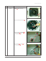
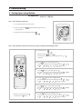
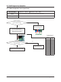
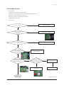
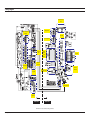
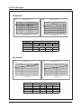
1
SYSTEM AIR CONDITIONER Model : JH035EAV Series JH026EAV Series UH035EAV Series UH026EAV Series Model Code : JH035EAV1 JH026EAV1 UH035EAV1 UH026EAV1 AIR CONDITIONER CONTENTS 1. Precautions 2. Product Specifications 3. Disassembly and Reassembly 4. Troubleshooting 5. Exploded Views and Parts List JH026EAV1 JH035EAV1 6. PCB Diagram and Parts List 7. Wiring Diagram 8. Schematic Diagram UH026EAV1 UH035EAV1 9. Reference Sheet Refer to the service manual in the GSPN(see the rear cover) for the more information. Operating Instructions and Installation Contents 11. Precautions ........................................................................................................................................ 1-1 1-1 Precautions for the Service ............................................................................................................. 1-1 1-2 Precautions for the Static Electricity and PL ................................................................................ 1-1 1-3 Precautions for the Safety ............................................................................................................... 1-1 12. Product Specifications ............................................................................................................... 2-1 .................................................................................................................... 2-1 ................................................................................................................ 2-2 2-3 Accessory and Option Specifications ........................................................................................................ 2-3 2-1 The Feature of Product 2-2 Specifications of Product 13. Disassembly and Reassembly .............................................................................................. 3-1 3-1 Indoor Unit ......................................................................................................................................... 3-2 3-2 Outdoor Unit 3-7 ..................................................................................................................................... 14. Troubleshooting ............................................................................................................................ 4-1 ....................................................................................................... 4-1 4-2 Things to check before diagnosis .................................................................................................. 4-4 ................................................................................................................ 4-4 4-1 Setting Option Setup Method 4-2-1 Display Error Mode .......................................................................................................................... 4-2-2 Outdoor Unit 4-6 4-2-3 Wired remote controller ....................................................................................................... 4-9 4-3 Fault Diagnosis by Symptom ......................................................................................................... 4-10 4-3-1 Indoor temperature sensor (open/short) .......................................................................... 4-12 ............................................. 4-13 ..................................................................................................................... 4-14 4-3-2 Indoor Heat Exchange temperature sensor (open/short) 4-3-3 Indoor Fan error ....................................................... 4-15 .................................................................................................. 4-16 ............................................................................................. ....................................................................... 4-17 4-18 ................................................................................ 4-19 ................................................................................................... 4-20 4-3-4 Communication error after completion of tracking 4-3-5 EEPROM circuit Part defect 4-3-6 MPI (micom plasmalon error) 4-3-7 When outdoor units cannot be turned on 4-3-8 DC link and over/lower voltage error 4-3-9 IPM and over current error 4-3-10 Compressor starting error, compressor locking error, compressor revolving error ............. 4-22 4-3-11 Outdoor temperature sensor error .................................................................................. 4-23 4-3-12 Emission temperature sensor error .................................................................................. 4-24 ........................................................................................ 4-25 ................................... 4-26 ................................................................................................................ 4-27 4-3-13 Cond temperature sensor error 4-3-14 Communication error between indoor/outdoor units (1min.) 4-3-15 Outdoor fan error ........................................................... 4-29 ................................................................................................................. 4-30 ...................................................................................................................................... 4-31 4-3-16 Discharge current error/ PFC over-current error 4-3-17 Gas leakage error 4-3-18 Other Samsung Electronics 1 Operating Instructions and Installation Contents 15. Exploded Views and Parts List 5-1 Indoor Unit ............................................................................................. 5-1 ........................................................................................................................................ 5-1 ..................................................................................................................................... 5-3 .............................................................................................................................. 5-5 5-2 Outdoor Unit 5-3 Ass’y Control Out 16. PCB Diagram and Parts List ................................................................................................... 6-1 ..................................................................................................................................... 6-1 6-1-1 Indoor Unit .............................................................................................................................. 6-1 6-1-2 Display PCB ............................................................................................................................. 6-2 6-1-3 Damper PBA............................................................................................................................. 6-2 6-1-4 Outdoor Unit .......................................................................................................................... 6-2 Parts List ............................................................................................................................................. 6-3 6-6 .............................................................................................................................. 6-7 .......................................................................................................................... 6-14 .............................................................................................................................. 7-1 6-1 PCB Diagram 6-2-1 Indoor Unit 6-2-2 Outdoor Unit 17. Wiring Diagram 18. Schematic Diagram ...................................................................................................................... 8-1 8-1 Indoor Unit ........................................................................................................................................ 8-1 ................................................................................................................................ 8-1 .................................................................................................................................... 8-2 .............................................................................................................................. 8-3 ..................................................................................................................................... 8-4 8-1-1 MAIN PCB 8-1-2 Damper 8-1-3 Pcb Display 8-2 Outdoor Unit 1 9. Reference Sheet .............................................................................................................................. 9-1 .................................................................................................................... 9-1 .......................................................................................................... 9-2 9-3 Pressure Graph .................................................................................................................................. 9-3 9-1 Index for Model Name 9-2 Refrigerating Cycle Diagram 2 Samsung Electronics 1. Precautions 1-1 Precautions for the Service Use the standard parts when replacing the electric parts. – Confirm the model name, rated voltage, rated current of the electric parts. Repair the disconnection of HARNESS securely when repairing the break down. – If there is any connection error, it causes an abnormal noise and incorrect operation. In case that you assemble or disassemble the products with laying it on the side, do work on the work cloth. – If not, the exterior of products can be scratched. Remove dust and foreign materials from harness, connection part, and inspection part thoroughly when repairing the break down. – It protects the danger of fire such as tracking and short. Tighten tightly the service valve of outdoor unit and the cap of charging valve with a monkey spanner. Check the assembly status of parts after repairing the break down. – It should be same as the status before repairing. 1-2 Precautions for the Static Electricity and PL As the PCB power terminal has a weakness for the static electricity, pay attention to it during the repair and measurement. – Work with insulation gloves during the repair and measurement of PCB. Check the distance between the product and the other electronic appliances such as TV, video, and audio. It should be over 2m. – If not, it causes a bad picture quality or a noise. Repairing the products by consumer should be strictly prohibited. – There is a danger of electric shock or fire due to incorrect disassembly. 1-3 Precautions for the Safety Do not pull any electric wires and do not touch an auxiliary power switch with a wet hand. – There is a danger of electric shock or fire. In case any wire or power plug has been damaged, replace it to eliminate any possible danger. Do not bend the power cord by force and do not put any heavy object on the power cord. – There is a danger of electric shock or fire. Do not use multi socket. – There is a danger of electric shock or fire. Ground the product if necessary. – Be sure to ground the product if there is any danger of electric leakage due to water or moisture. Be sure to turn off the auxiliary power switch or pull out the power plug during replacement or repair of electric parts. – There is a danger of electric shock. In case the product will not be in use for a long time, the battery of remote control should be kept separately. – Leakage of inside fluid can cause break down of remote control. Samsung Electronics 1-1 2. Product Specifications 2-1 The Feature of Product What is a Console type Air Conditioner? Floor standing type Air Conditioner, Powerful on floor heating & cooling. MPI Zone (Air cleaning solution) Samsung’s Micro Plasma Ion Zone is a technology that generates activated hydrogen and oxygen ions, which exterminates viruses and allergy-causing microbes in the air by neutralizing them and turning into water. Special Filter Allergy Filter, Deodorizing Filter and Anti-bacteria Filter will make air so pure. Flexible Pipe Installation Anywhere it can be installed by 6way piping. Elegance Design Slim Design(199mm), Clean Front Panel, Luxurious Wide Display Mirror & Lamp 2-1 Samsung Electronics Product Specifications 2-2 The Specifications of Product Item Model Name JH026EAV 1 JH035EAV 1 UH026EAV1 UH035EAV1 Indoor Unit Design Outdoor Unit Remote Control Power specifications Single phase, 220~240V, 50Hz Indoor W×H×D mm 720X620X199 Outdoor W×H×D mm 790X548X285 Indoor Unit kg 15.2 Outdoor Unit kg 35.5 Cooling(Min/Nor/Max) w 980/2,600/3,500 990/3,500/4,100 Heating(Min/Nor/Max) w 950/3,500/4,600 990/4,000/4,900 Cooling(Min/Nor/Max) w 230/670/1,040 250/1,030/1,340 Heating(Min/Nor/Max) w 210/970/1,250 210/1,105/1,350 Cooling(Min/Nor/Max) A 1.5/3.3/4.9 1.7/4.9/6.2 Heating(Min/Nor/Max) A 1.4/4.7/6.2 1.4/5.3/6.5 Size Weight Capacity Power consumption Running current g 950 High pressure side 1/4" Low pressure side 3/8" Additional amount of refrigerant(per 1m) g chargeless Basic pipe length m 5 Max. allowable pipe length m 20 Max. allowable head drop for outside pipe m 15 Amount of basic refrigerant(NET) Connecting pipes Option code Samsung Electronics 087777-1380B6 087777-1580D8 2-2 2-3 Accessory and Option Specifications Accessories Item 2-3 Descriptions Code-No. Q'TY User’s manual DB98-29147A 1 Installation manual DB98-29148A 1 Insulation install out B62-05580V 1 Insulation Install SVC DB62-05691C 1 Cable-tie DB65-10088C 4 Wireless remote control DB93-06280F 1 Battery DB47-90024A 2 Remark Basic/ Indoor Samsung Electronics Product Specifications Wired Remote Controller ( option resource) Item Samsung Electronics Descriptions Code-No. Q'TY Wired remote controller DB93-01766H 1 Cable-tie DB65-10088B 2 Cable clamp DB65-10074E 5 M4x16 tapped screw 6002-000474 7 Indoor unit power drawing cable DB39-00221A 1 Communication cable of the wired remote controller DB39-00933A 1 Wire joint DB39-90020A 1 User manual DB98-15731A 1 Installation manual DB98-15770A 1 Remark 2-4 Product Specifications Centralized Controller Item Descriptions Code-No. Q'TY Centralized controller DB93-03425C 1 Cable-tie DB65-10088B 2 Cable clamp DB65-10074E 5 M4x16 tapped screw 6002-000474 7 User manual DB98-12721A 1 Installation manual DB98-25773A 1 Descriptions Code-No. Q'TY Function controller DB93-00757G 1 Cable-tie DB65-10088B 2 Cable clamp DB65-10074E 6 M4x16 tapped screw 6002-000474 7 User manual DB98-27317A 1 Installation manual DB98-27315A 1 Remark Function Controller Item 2-5 Remark Samsung Electronics Product Specifications Transmitter Item Samsung Electronics Descriptions Code-No. Q'TY Transmitter DB93-03374C 1 Transmitter power cable DB39-00378D 1 Transmitter communication cable DB39-00253D 1 Remark 2-6 3. Disassembly and Reassembly Necessary Tools Item Remark +SCREW DRIVER MONKEY SPANNER 3-1 Samsung Electronics 3-1 Indoor Unit No Parts 1 Cabi Parts Procedure 1) Remark Open the Panel Front( ). Remove the Clip Wire( ). 2) Release 4 screws on the Body Front(©). © 3) Open the Body Front(©) by pulling from bottom of the part. © Samsung Electronics 3-2 Disassembly and Reassembly No Parts 2 Electrical Parts Procedure Remark 1) Open the cover of Control Box ). 2) Pull the PBA out along the slide guide. 3-3 3) Cut the Cable tie. 4) Pull all wires out from the PBA. Samsung Electronics Disassembly and Reassembly No Parts Procedure Remark 5) Release the 2 screws. (one is top of the C-Box, the other is left of it) 6) Release 2 Hold Wires and pull all wires out from it . 3 Blowing 1) Pull the Bracket Pipe( )out. & Evap Part 2) Release 2 screws and pull Top Discharge Kit( ) out. Samsung Electronics 3-4 Disassembly and Reassembly No Parts Procedure Remark 3) Release 2 screws and pull Bottom Discharge Kit( ) out. 4) Disconect the Step Motor wire( ) from the conect wire . This part is right side of the Bottom Discharge Kit( ). 5) Pull Bottom Discharge Kit( ) Out from the bottom of it. 6) Release 3 screws and pull the Evap out from top to bottom direction. 3-5 Samsung Electronics Disassembly and Reassembly No Parts 4 Fan Part Procedure Remark 1) Release 1 screw and pull the Bell Mouth ( ) out. 2) Release the Nut and pull Fan Turbo( )out. 3) Release 6 screw on the Body Back( ). Pull the Cap MPI( ), Bracket Wire( ) and Bracket Motor( ) out. 4) Pull the MPI Kit( ) and Motor( ) out from the Body Back( ). Samsung Electronics 3-6 3-2 Outdoor Unit No Parts 1 Common Work Procedure Remark Before disassembly, please make sure to shut off the power. 1) Separate fixing screw in the Cover Side. (Use +Screw Driver.) 2) Undo the 4 fixing screws on the left and right cabinet Side Edges then undo the screws on the lower front to separate the Cabinet Front. (Use +Screw Driver.) 3) Separate the Cabinet Front as shown on the right picture. 4) Undo fixing screw to remove Plate Control Out on the Cabinet Side RH. (Use +Screw Driver.) 3-7 Samsung Electronics Disassembly and Reassembly No Parts Procedure Remark 5) Undo 2 fixing screws on the backside of the Cabinet Side RH. (Use +Screw Driver.) 6) Undo 3 fixing screws to assemble Bracket Valve on the Cabinet Side RH. (Use +Screw Driver.) 7) Undo 2 fixing screws on the Cabinet Side LF. (Use +Screw Driver.) Samsung Electronics 3-8 Disassembly and Reassembly No Parts 2 Ass'y Control Out Procedure Remark 1) Separate the Motor wire from the PCB of the Ass’y Control Out. 2) Separate several Connectors from the PCB of the Ass’y Control Out. 3) Separate 2 Connect Wires from the Reactor. 4) Undo a fixing screw to assemble the Ass’y Control Out on the Partition. (Use +Screw Driver.) 3-9 Samsung Electronics Disassembly and Reassembly No Parts Procedure 3 Fan & Motor 1) Release refrigerant first. 2) Undo the fixing screw. (Use +Screw Driver.) 3) Separate the induction and outlet pipes with a Welding Torch. (Use Monkey Spanner.) 4) Separate the Fan and Motor. 4 Heat Exchanger Remark 1) Undo 2 fixing screws. (Use +Screw Driver.) 2) Separate the induction and outlet pipes with a Welding Torch. 3) Separate the Heat Exchanger. Please wear gloves when working as there is a possibility of cutting your hand. 5 Ass'y Valve 4 way & Ass'y Valve EEV 1) Undo 4 fixing bolts to assemble a Valve Service on the Bracket Valve as shown in the right picture. (Use Monkey Spanner.) When separating Compressor, Heat Exchanger and pipes please ensure that Compressor is completely free from any remaining refrigerant then separate all pipes with welding torch. Ass'y Valve 4 Way 1) Separate 3 welded parts. Samsung Electronics 3-10 Disassembly and Reassembly No Parts Procedure Remark Ass'y Valve EEV 1) Separate 1 welded parts. 6 3-11 Compressor 1) Undo nuts on the Terminal Cover. 2) Separate the Terminal Cover and then Connect Wires from the Compressor. 3) Separate the Felt Comp Sound. 4) Undo 3 bolts on the flow of the Compressor as shown in the right-hand picture. (Use Monkey Spanner.) Samsung Electronics 4. Troubleshooting 4-1 Setting Option Setup Method ex) Option No. : Step 1 : Enter the Option Setup mode. 1st Take out the batteries of remote control. 2nd Press the temperature the battery again. button simultaneously and insert 3rd Make sure the remocon display shown as . Step 2 : Enter the Option Setup mode and select your option according to the following procedure. 1 The default value is . button to . Otherwise, push the Every time you push the button, the display panel reads or repeatedly. 2 3 1 button to set the display panel to . Push the 10 Every time you push the button, the display panel reads Push the button to set the display panel to . Every time you push the button, the display panel reads button to set the display panel to . Push the Every time you push the button, the display panel reads Push the button to set the display panel to . Every time you push the button, the display panel reads . . . repeatedly. 2 3 4 Silence 5 Push the button to set the display panel to . Every time you push the button, the display panel reads . . . repeatedly. 6 4 . . . repeatedly. 5 . . . repeatedly. Setting is not required if you must a value which has a Samsung Electronics default. 6 . . . repeatedly. 4-1 Troubleshooting 7 1 Press button, then the default value is . 8 9 Push the button to set the display panel to . Every time you push the button, the display panel reads button to set the display panel to . Push the Every time you push the button, the display panel reads button to set the display panel to . Push the Every time you push the button, the display panel reads Push the button to set the display panel to . Every time you push the button, the display panel reads button to set the display panel to . Push the Every time you push the button, the display panel reads . . . repeatedly. 8 9 7 10 Silence 11 . . . repeatedly. 12 10 . . . repeatedly. 11 . . . repeatedly. 12 Setting is not required if you must a value which has a default. . . . repeatedly. Step 3 : Upon completion of the selection, check you made right selections. Press the Mode Selection key, to set the display part to The display part shows . Press the Mode Selection key, to set the display part to The display part shows . and check the display part. and check the display part. Step 4 : Pressing the ON/OFF button ( ) When pressing the operation ON/OFF key with the direction of remote control for unit, the sound ’’Ding’’ or ’’Diriring’’ is heard and the OPERATION ICON( ) lamp of the display is flickering at the same time, then the input of option is completed. (If the diriring sound isn’t heard, try again pressing the ON/OFF button.) Step 5 : Unit operation test-run First, Remove the battery from the remote control. Second, Re-insert the battery into the remote control. Third, Press ON/OFF key with the direction of remote control for set. • Error Mode 1st 2nd 4-2 If all lamps of indoor unit are flickering, Plug out, plug in power plug again and press ON/OFF key to retry. If the unit is not working properly or all lamps are continuously flickering after setting the option code, see if the correct option code is set up for its model. Samsung Electronics Troubleshooting Option Items SEGMENT SEG1 SEG2 SEG3 SEG4 SEG5 SEG6 SEG7 SEG8 SEG9 JH026EAV1 0 8 7 7 7 7 1 3 8 0 B 6 JH035EAV1 0 8 7 7 7 7 1 5 8 0 D 8 MODEL Samsung Electronics SEG10 SEG11 SEG12 4-3 4-2 Things to check before diagnosis If an error occurs during the operation, one or more LED flickers and the operation is stopped except the LED. If you re-operate the air conditioner, it operates normally at first, then detect an error again. 4-2-1 Display Error mode LED lamp display White Abnormal conditions X Power reset Error of temperature sensor in the indoor unit (Open/Short) X Error of heat exchanger sensor in the indoor unit X Remarks X X X X X X X X Error of the outdoor temperature sensor X Error of the condensor temperature sensor X X Error of the discharge temperature sensor 1. Indoor and outdoor unit time out 2. Abnormal data reception more than 60 packet 3. Indoor unit is not connected 4. Communication error between the outdoor unit Main-Inverter Micom(After 1 minute of MainInverter detection) On Flickering X X X 1. Indoor unit error (Display is unrelated with operation) 2. Outdoor unit error (Display is unrelated with operation) X Off If you turn off the air conditioner when the LED is flickering, the LED is also turned off. 4-4 Samsung Electronics Troubleshooting Display Error mode(Cont.) LED lamp display White Abnormal conditions Remarks X X X X Detection of the float switch X X X Error of setting option switches for optional accessories X X X Communication error between indoor units [Self diagnosis]Power voltage detection between indoor and outdoor unit communication cable [Self diagnosis]Outdoor unit refrigerant leakage(Gas leak) [Self diagnosis]Outdoor fan restriction error [Inverter]Inverter compressor operation failure [Inverter] DC peak error [Inverter]DC Link voltage 150V or less, 410V or more X [Inverter] Compressor rotation error [Inverter]Electric current error [Inverter]DC Link sensor error [Inverter]EEPROM READ/WRITE error [Inverter]Inverter zerocrossing error Setting the outdoor unit capacity option error X EEPROM error X EEPROM option error X MPI no feedback Error On Flickering X X X X Off If you turn off the air conditioner when the LED is flickering, the LED is also turned off. Samsung Electronics 4-5 Troubleshooting 4-2-2 Outdoor Unit SUB PCB 7-Segment Diplay Product operation status in case of error Content Measures Number of Times Outdoor unit compressor/ outdoor unit fan Indoor unit communication error(1min.) • Check the communication line for indoor units • Check the power supply of the communication phase(DC) 1 Time Operation-off Communication time-out error(2min.) • Check the communication line for indoor units • Check the power supply of the communication phase(DC) 1 Time Operation-off Indoor temperature sensor • Check the temp. sensor of the indoor unit room • Check the indoor PCB connector 1 Time Operation-off Indoor unit EVA IN sensor • Check the indoor unit drainage pipe sensor • Check the indoor PCB connector 1 Time Operation-off Indoor unit EVA OUT sensor • Check the indoor unit drainage pipe sensor • Check the indoor PCB connector 1 Time Operation-off Dismount of indoor unit EVA IN sensor • Check the drainage pipe has been dismounted 1 Time Operation-off Dismount of indoor unit EVA OUT sensor • Check the drainage pipe has been dismounted 1 Time Operation-off Secondary detection of indoor floating switch • Check the indoor unit's float sensor • Check the indoor PCB connector 1 Time Operation-off Indoor fan error • Check the indoor PCB connector 1 Time Operation-off Indoor eeprom error • Check the EEPROM data • Check the indoor's option 1 Time Operation-off Indoor eeprom option error • Check the EEPROM data • Check the indoor's option 1 Time Operation-off :OFF 4-6 :ON◎:BLINK Samsung Electronics Operating Instructions and Installation Outdoor Unit(cont.) Product operation status in case of error SUB PCB 7-Segment Diplay Content Indoor unit not connected 1min. Time out Comm. (Display Board : Onboard : Indoor ↔ Outdoor) Measures Number of Times Outdoor unit compressor/ outdoor unit fan • Check the indoor unit connection • Check the indoor unit number(multi only) 1 Time Operation-off • Check the indoor unit connection • Check the indoor unit option 1 Time Operation-off Abnormal Serial communication(Display Board: - - Indoor ↔ Outdoor) - - Outdoor temp sensor error (Dual/Single) • Check the connection status of the sensor • Check the sensor location • Check the risistance values of sensor 1 Time Operation-off Cond temp sensor error (Dual/Single) • Check the connection status of the sensor • Check the sensor location • Check the risistance values of sensor 1 Time Operation-off Discharge temp sensor error (Dual/Single) • Check the connection status of the sensor • Check the sensor location • Check the risistance values of sensor 1 Time Operation-off Discharge over temperature (Dual/Single) - 3 Times Operation-off • Check the operation status of operation mode • Check the temp. sensor 1 Time Operation-off Fan error • Check the input power connection status • Check the connection status between the motor and PCB in outdoor unit • Check the fuse of indoor/outdoor units 1 Time Operation-off Comp Starting error • Check the connection status of the compressor • Check the resistand between different phases in compressor 5 Times Operation-off I_Trip error / PFC Over current • Check the input power • Check the refrigerant is filled • Check the outdoor fan operation normally 3 Times Operation-off IPM Over Current(O.C) • Check the refrigerant is filled • Check the connection status of compressor and if it operates normally • Check for any obstacles around indoor/outdoor units 9 Times Operation-off - Operation condition secession(HEATING) Operation condition secession(COOLING) :OFF Samsung Electronics :ON◎:BLINK 4-7 Operating Instructions and Installation Outdoor Unit(cont.) Product operation status in case of error SUB PCB 7-Segment Diplay Content Measures Number of Times Outdoor unit compressor/ outdoor unit fan 9 Times Operation-off - Restart(after 3min.) Comp Vlimit error • Check the connection status of compressor • Check the resistance between different phases in compressor DC-Link voltage under/ over error • Check the connection of input power Comp rotation error • Check the connection status of the compressor • Check the resistance between different phases in compressor 3 Times Operation-off Current sensor error • Check the PCB operates normally 1 Time Operation-off DC-Link valtage sensor error • Check the connection of input power 1 Time Operation-off OTP error • Check the PCB operates normally 1 Time Operation-off AC Line Zero Cross Signal out • Check the connection of input power 1 Time Operation-off Comp Lock error • Check the connection status of the compressor • Check the resistance between different phases in compressor 3 Times Operation-off Fan error(two fan outdoor) • Check the input power connection status • Check the connection status between the motor and PCB in outdoor unit • Check the fuse of indoor/outdoor units 1 Time Operation-off GAS Leak error(Dual/Single) • Check refrigerant is filled • Check the indoor EVA sensor 3 Times Operation-off Capacity miss match • Check the indoor unit's option code • Check the capacity of indoor unit's and outdoor unit's 1 Time Operation-off :OFF 4-8 :ON◎:BLINK Samsung Electronics Troubleshooting 4-2-3 Wired remote controller(Option resource) - If an error occurs is displayed on the wired remote controller. - To see an error code, please press the test button. Error mode Content Measures Product operation status in case of error Outdoor unit compressor/ outdoor unit fan Error type Indoor unit communication error Check the communication line for indoor units, check the power supply of the communication phase (DC) Operation-off Communication error Communication time-out error between indoor/outdoor unit 6-packet over error Check the communication line for indoor units, check the power supply of the communication phase (DC) Operation-off Communication error Indoor temperature sensor (open/short error) Check the temp. sensor of the indoor unit room. Check the indoor PCB connector CN21(white) Operation-off Indoor sensor error Indoor unit Eva In sensor (open/short) Check the indoor unit drainage pipe sensor Check the indoor PCB connector CN21 (white) Operation-off Indoor sensor error Dismount of indoor unit Eva In sensor Check the drainage pipe has been dismounted Operation-off Indoor sensor error Secondary detection of indoor floating switch Check the indoor unit’s float sensor Check the indoor PCB connector CN51 (black) Operation-off Self-diagnosis error Indoor unit not connected Check the indoor unit connection Check the indoor unit option Operation-off Communication error - Communication error Check the connection status of the sensor Outdoor temperature sensor error Check the sensor location Check the resistance values of sensor Operation-off Outdoor sensor error Cond. temperature sensor error Check the connection status of the sensor Check the sensor location Check the resistance values of sensor Operation-off Outdoor sensor error [inverter] Emission temperature sensor error Check the connection status of the sensor Check the sensor location Check the resistance values of sensor Operation-off Outdoor sensor error Excessive temperature emission Not an error (discharge temp. control) - Outdoor unit protection control error Power cable connection error Check the status of power connection Operation-off Outdoor sensor error Communication error between Check the Main MICOM indoor/outdoor unit INV and Main Check the inverter MICOM Micom (1 min.) Samsung Electronics 4-9 Operating Instructions and Installation Troubleshooting Wired remote controller (cont.) - If an error occurs is displayed on the wired remote controller. - To see an error code, please press the test button. Error mode 4-10 Content Measures Product operation status in case of error Outdoor unit compressor/ outdoor unit fan Error type Non-connection error of indoor and outdoor Communication wire (connected to the power terminal) Check the status of power connection Check the connection status of the communication line Operation-off Self-diagnosis error Outdoor fan 1 error Check the input power connection status Check the connection status between the motor and PCB in outdoor unit Check the fuse of indoor/outdoor units Operation-off Self-diagnosis error [inverter] Compressor operation error Check the connection status of the compressor Check the resistance between different phases in compressor Operation-off Outdoor unit protection control error Discharge current error/ PFC over-current error Check the input power Check refrigerant is filled Check outdoor fan operates normally Operation-off Outdoor unit protection control error [inverter] IPM over current error Check refrigerant is filled Check the connection status of compressor and if it operates normally Check for any obstacles around indoor/ outdoor units Operation-off Outdoor unit protection control error [inverter] Compressor rotation error Check the connection status of the compressor Check the resistance between different phases in compressor Operation-off Outdoor unit protection control error [inverter] Current sensor error Check PCB operates normally Operation-off Outdoor unit protection control error [inverter] DC link voltage sensor error Check the connection of input power Check the status of RY21 and R2000 of Inverter PCB Operation-off Outdoor unit protection control error [inverter] OTP error Check PCB operates normally Operation-off Outdoor unit protection control error Outdoor fan 2 error Check the connection status of input power Check the connection status of motor and outdoor PCB Check the fuse of indoor/outdoor unit Operation-off Self-diagnosis error Gas leakage error Check refrigerant is filled Check the indoor EVA sensor Operation-off Self-diagnosis error Inconsistent volume Check the indoor unit’s option code Operation-off Outdoor unit protection control error Samsung Electronics Operating InstructionsTroubleshooting and Installation Wired remote controller (cont.) - If an error occurs is displayed on the wired remote controller. - To see an error code, please press the test button. Error mode Content Measures Product operation status in case of error Outdoor unit compressor/ outdoor unit fan Error type Communication error between indoor unit and wired remote controller Check the connection wire linking indoor unit and wired remote controller Normal operation Wired remote controller control error Communication error between master and slave wired remote controller Check the option switch that distinguishes master and slave (Available only for 1 master unit and 1 slave unit) Normal operation Wired remote controller control error Cross installation error of COM1/ COM2 Check the connection of outdoor unit and wired remote controller is linked to Com2 terminal of the indoor unit Normal operation Wired remote controller control error Wired remote controller COM2 setting option error Check the Dip switch for Com1 and Com2 is set to Com2 Normal operation Wired remote controller control error Samsung Electronics 4-11 4-3 Fault Diagnosis by Symptom 4-3-1 Indoor temperature sensor (open/short) Indoor unit display Criteria X(Operation) X(Defrost) (Reservation) X(Fan) X(MPI) In case of disconnection or short-circuit of the indoor temperature sensors Cause of problem Disconnection or short-circuit of the relevant sensors Is indoor temp. sensor connector disconnected? Yes Resume operation after connecting to the connector PCB No Disconnect the PCB from the connector of the internal temp. sensor and then measure the resistance between the two terminals. ex) Room temperature 26°C~ resistance 09.26KΩ At that time, does the resistance value deviate from the temp. table beside? No Resume operation after replacing PCB 4-12 <Temperature sensor resistance values> Yes Indoor temp. sensor self-defect (replacement) Current Temp. (°C) Resistance (KΩ) 40 5.800 35 6.900 30 8.300 25 10.00 20 12.10 15 14.70 10 18.00 5 22.00 0 28.30 -5 33.90 -10 42.30 Samsung Electronics Operating InstructionsTroubleshooting and Installation 4-3-2 Indoor Heat Exchange temperature sensor (open/short) Indoor unit display Criteria X(Operation) X(Defrost) (Reservation) X(Fan) (MPI) In case of disconnection or short-circuit of the heat exchanger of indoor temperature Cause of problem Disconnection or short-circuit of the relevant sensors Is indoor Heat Exchange temp. sensor connector disconnected? Yes Resume operation after connecting to the connector PCB No Disconnect the PCB from the connector of the internal temp. sensor and then measure the resistance between the two terminals. ex) Room temperature 24°C~ resistance 10.93KΩ At that time, does the resistance value deviate from the temperature table beside? No Resume operation after replacing PCB Samsung Electronics <Temperature sensor resistance values> Yes Indoor Heat Exchange temp. sensor self-defect (replacement) Current Temp. (°C) Resistance (KΩ) 40 5.800 35 6.900 30 8.300 25 10.00 20 12.10 15 14.70 10 18.00 5 22.00 0 28.30 -5 33.90 -10 42.30 4-13 Operating Instructions and Installation Troubleshooting 4-3-3 Indoor Fan error Indoor unit display Criteria X(Operation) (Defrost) Reservation) X(Fan) X(MPI) Indoor fan being non-operative/ stop after excessive high speed Cause of problem Check for motor connector disconnect/ check motor fan fastening Is Motor connector disconnected from the PCB? Yes Resume operation after connecting to the connector PCB No Is there any clogging (binding) of foreign substances in the MotorFan? No Yes Resume operation after removing the foreign substances. Resume operation after replacing PCB 4-14 Samsung Electronics Operating InstructionsTroubleshooting and Installation 4-3-4 Communication error after completion of tracking Indoor unit display (Operation) Criteria Defrost) (Reservation) X(Fan) X(MPI) If communication between indoor and outdoor units has been blocked for 2 minutes during operation Cause of problem Communication error between indoor and outdoor unit Replace PCB of indoor unit after checking out the communication line After removing the communication line that links outdoor to indoor units measure 2 lines of the outdoor unit with scope. At this time, the voltage between lines is a square wave that is above DC±0.7V as shown in the picture below No Replace PCB after checking the communication line of the outdoor unit PCB and connector Yes After reconnecting the communication line that links outdoor and indoor units, remove communication connector in the indoor PCB. If communication does not work during operation, replace PCB of the indoor unit. Good defect +0.7V -0.7V Samsung Electronics 4-15 Operating Instructions and Installation Troubleshooting 4-3-5 EEPROM circuit part defect Indoor unit display Criteria (Operation) X(Defrost) (Reservation) (Fan) X(Filter) EEPROM circuit part defect Cause of problem EEPROM component defect/ necessary component missing in EEPROM circuit part/ damage/ soldering If the circuit part of the EEPROM is okay (necessary component missing in EEPROM circuit part/ damage/ soldering defect) No Yes Resume operation after repairing it according to P8-2 circuit diagram’s EEPROM part, P6~6-10 component list. If problem occurs during re-operation, replace PCB Resume operation after replacing PCB 4-16 Samsung Electronics Operating InstructionsTroubleshooting and Installation 4-3-6MPI(Micro PlasmaIon) error Indoor unit display (MPI) X(Fan) X(Reservation) X(Defrost) X(Operation) Criteria On MPI non-operation Cause of problem Flickering Check for MPI connector disconnect X Off Is MPI Connector disconnected from the PCB? Yes Resume operation using ion counter after connecting to the connector PCB No Measure the amount of Ion with tester. MPI Kit Tester: ITC201A Yes THE NUMBER OF MEASURED ION IS MORE THAN 100,000. Normal operation Change the MPI Kit (it’s out of the work) Samsung Electronics 4-17 Operating Instructions and Installation 4-3-7When outdoor units cannot be turned on 1. Cause of the breakdown 1) Is power voltage 220V? 2) Is AC power properly connected? 3) Are the LEDs of Main PCB and inverter PCB of the outdoor unit on? 4) Is the power supply of the outdoor unit 220V? 2. Inspection order Switch off the main power (breaker or power outlet) then turn on again after 30 seconds. Is the voltage of N-L of the outdoor unit’s PCB AC187V~AC253V? Check and replace the wire that connects the outdoor terminal block to outdoor unit’s PCB (contact point, short-circuit) No Yes Is the voltage of the both side of BD01, “~” and “~” of the outdoor unit’s Main PCB AC187V~AC253V? Yes Is the resistance value of R001 180Ω~220Ω? No R001 Resistance replacement Yes Is the voltage of C101 chemical condenser of the outdoor units’ Main PCB DC265V~DC357V? No Bridge 10de replacement (DB300) Yes Is reactor 1 and 2 (reactor connection wire) properly connected to the reactor? No Connect the connection wire of the reactor Yes Yes Replace outdoor unit PCB for Outdoor MICOM defect. Power ok? No Yes Finish 4-18 Samsung Electronics Operating Instructions and Installation 4-3-8 DC link and over/lower voltage error 1. Inspection items 1) Is compressor operating properly? 2) Is there a connection between input power and power? 2. Inspection order Is EMI PCB and Inverter PCB connected properly? No Turn off the power then reconnect Yes Replace PCB Samsung Electronics 4-19 Operating Instructions and Installation Troubleshooting 4-3-9 IPM and over current error 1. Inspection items 1) Is refrigerant filled? 2) Is the compressor operating without a problem? 3) Is the compressor connected properly? 4) Are there any obstacles around the indoor/outdoor units? 2. Inspection order Are outdoor/indoor units installed correctly? No Reinstall after removing obstacles Yes Are screws fasten in PBA? (IPM, DIODE, B/D, IGBT) No Tighten the screws firmly Yes Is service valve completely opened? No Open valves Yes Is the compressor connection line properly connected to the compressor? No Check the connection status of the compressor Yes Are the values for current sensing resistance within R418-19mΩ-21mΩ No Resistance replacement Yes Is resistance value of the different compressor phases (UV, V W, W U) less than 2Ω? No Compressor replacement Yes Continue (continued on the back) 4-20 Samsung Electronics Operating InstructionsTroubleshooting and Installation IPM and over current error (cont.) Continued Is the resistance between the Compressor body and chassis Maga Ω? No Replace compressor Yes Are the location of the temperature sensor and measurement value normal? No Turn off the power then reconnect the cable No Turn off the power then correct the sensor location or replace it Yes Is the connection cable between the compressor and PCB properly connected? Yes Replace PCB Samsung Electronics 4-21 Operating Instructions and Installation Troubleshooting 4-3-10 Compressor starting error, compressor locking error, compressor revolving error 1. Inspection items 1) Is the connection line between power and the compressor properly connected? 2) Is the resistance between different compressor phases normal? 2. Inspection order Restart after turning off the power Did error occur? No Terminate the service Yes Is resistance value of the different Compressor phases (UV, V W, W U) less than 2Ω? No Replace the Compressor Yes Is the resistance between the Compressor body and chassis Maga Ω? No Replace the Compressor Yes Is the Compressor connection line properly connected to the Compressor? No Check the connection line Yes Replace the outdoor unit’s PCB 4-22 Samsung Electronics Operating InstructionsTroubleshooting and Installation 4-3-11 Outdoor temperature sensor error 1. Inspection items 1) Are the sensors connected properly? 2) Are the sensors located properly? 3) Do the resistance values of the sensors satisfy each temperature? 2. Inspection order Power off Are connectors properly connected to the relevant colors? No Reconnect the temperature sensor connector No Reconnect the temperature sensor connector Yes Are temperature sensors connected without separation? Yes When measuring the resistance of both sides with a single temperature sensor, does it indicate 10KΩ at room temperature of 25°C? Yes Power on Yes After assembling the temperature sensors on PCB check the voltage of both sides. Do they indicate DC1V~DC4V? No Replace temperature sensor <Temperature sensor resistance values> Current Current Resistance Resistance temperature temperature (KΩ) (KΩ) (°C) (°C) 70 4 20 12 60 5 10 20 50 6 0 30 40 7 -10 40 30 8 No ex) Room temperature 24°C ~ resistance 10.28kΩ Replace PCB after turning off the power Yes Is there a short circuit or defective contact in the sensor wires? No Replace temperature sensor after turning off the power Yes Replace PCB after turning off the power Samsung Electronics 4-23 Operating Instructions and Installation Troubleshooting 4-3-12 Emission temperature sensor error 1. Inspection items 1) Are the sensors connected properly? 2) Are the sensors located properly? 3) Do the resistance values of the sensors satisfy each temperature? 2. Inspection order Power off Are connectors properly connected to the relevant colors? No Reconnect the temperature sensor connector No Reconnect the temperature sensor connector Yes Are temperature sensors connected without separation? Yes When measuring the resistance of both sides with a single temperature sensor, does it indicate 200KΩ at room temperature of 25°C? Yes Power on Yes After assembling the temperature sensors on PCB check the voltage of both sides. Do they indicate DC1V~DC4V? No Replace temperature sensor <Temperature sensor resistance values> Current Current Resistance Resistance temperature temperature (KΩ) (KΩ) (°C) (°C) 80 40 30 180 70 50 20 220 60 60 10 320 50 90 0 550 40 110 No ex) Room temperature 23°C ~ resistance 205.4kΩ Replace PCB after turning off the power Yes Is there a short circuit or defective contact in the sensor wires? No Replace temperature sensor after turning off the power Yes Replace PCB after turning off the power 4-24 Samsung Electronics Operating InstructionsTroubleshooting and Installation 4-3-13 Cond temperature sensor error 1. Inspection items 1) Are the sensors connected properly? 2) Are the sensors located properly? 3) Do the resistance values of the sensors satisfy each temperature? 2. Inspection order Power off Are connectors properly connected to the relevant colors? No Reconnect the temperature sensor connector No Reconnect the temperature sensor connector Yes Are temperature sensors connected without separation? Yes When measuring the resistance of both sides with a single temperature sensor, does it indicate 10KΩ at room temperature of 25°C? Yes Power on Yes After assembling the temperature sensors on PCB check the voltage of both sides. Do they indicate DC1V~DC4V? No Replace temperature sensor <Temperature sensor resistance values> Current Current Resistance Resistance temperature temperature (KΩ) (KΩ) (°C) (°C) 70 4 20 60 5 10 20 50 6 0 30 40 7 -10 40 30 8 No ex) Room temperature 24.5°C ~ resistance 10.17kΩ 12 Replace PCB after turning off the power Yes Is there a short circuit or defective contact in the sensor wires? No Replace temperature sensor after turning off the power Yes Replace PCB after turning off the power Samsung Electronics 4-25 Operating Instructions and Installation Troubleshooting 4-3-14 Communication error between indoor/outdoor units (1min.) 1. Inspection items 1) Is the communication line between indoor and outdoor units connected properly? 2) Is there a communication connection between power line and communication line? 2. Inspection order Restart after turning off the power Is there a communication error? No Terminate service Yes Is there a communication connection between power line and communication line? No Connection line checkup Yes Is the outdoor terminal block F1–F2, less than DC5V? No Replace PCB of the outdoor unit after turning off. Yes When measuring F1–F2, the outdoor terminal block, if the voltage varies (communicates) below DC5V, the connection status of the connection line is normal. 4-26 Samsung Electronics Operating InstructionsTroubleshooting and Installation 4-3-15 Outdoor fan error 1. Inspection items 1) Is input power and power connected properly? 2) Is motor connection line properly connected to the PCB of the outdoor unit? 3) Is the fuse for indoor/outdoor unit connected? 4) Are there any obstacles around Motor or Propeller? 5) Is Motor Driver out of order? 2. Inspection order No Check fan is locked Remove the Fan lock Yes No Is the connection between Fan and PCB proper? Reconnect the connector Yes No Replace the Fan Does the color of fire wire match? Yes Is the voltage of the No.1 and No. 3 pin of the CN71 between 250V~350V? No Check if the outdoor unit’s power supply is defective Yes Is the voltage of the No.1 and No. 3 pin of the CN01 between 1V~5V? Is there any change in the voltage of the no.13 pin of the IC01 (MICOM)? No Replace the main PCB of the outdoor unit Yes Yes Replace the main PCB of the outdoor unit Defective MICOM Continue (continued on the back) Samsung Electronics 4-27 Operating Instructions and Installation Troubleshooting Outdoor fan error (cont.) Continued Is there any change in the voltage of the no 3 pin and no.6 pin of the IC01 (MICOM)? Yes No 30 seconds after turning off the power, separate BLDC Fan connector CN71 Is there any change in the voltage of the no.13 pin of the IC01 (MICOM)? No Replace the main PCB of the outdoor unit Yes Replace the main PCB of the outdoor unit 4-28 Replace BLDC fan motor Samsung Electronics Operating InstructionsTroubleshooting and Installation 4-3-16 Discharge current error/ PFC over-current error 1. Inspection items 1) Is input power correct? 2) Is refrigerant filled? 3) Is the outdoor fan spinning correctly? 4) Are there any obstacles around indoor/outdoor units? 2. Inspection order Is the outdoor unit installed correctly? No Reinstall after removing obstacle Yes Is indoor unit installed correctly? No Reinstall after removing obstacle Yes Is the compressor operating normally? No Replace the compressor Yes Is the service valve open completely? No Open valves Yes Replace PCB Samsung Electronics 4-29 Operating Instructions and Installation Troubleshooting 4-3-17 Gas leakage error 1. Inspection items 1) Is refrigerant filled? 2) Is the indoor EVA sensor connected properly? 2. Inspection order Restart after turning off the power Did error occur? No Terminate the service Yes Is resistance value of the different Compressor phases (UV, V W, W U) less than 2Ω? No Replace the compressor Yes No Is the service valve open completely? Open valves Yes Is the indoor EVA sensor connected properly? No Reconnect the sensor connector Yes No Is refrigerant filled? ace th Yes Replace the outdoor unit’s PCB 4-30 Samsung Electronics Operating InstructionsTroubleshooting and Installation 4-3-18 Other 1. Current sensor error Check PCB operates normally then replace the PCB 2. Compressor V limit error Check the compressor operates normally then replace the compressor. If an error still occurs after the replacement of the compressor, replace the PCB 3. OTP error Check PCB operates normally then replace the PCB 4. DC link Voltage Sensor Error Check the connection between input power and the power is okay then replace the PCB 5. AC zero Crossing signal out error Check the connection between input power and the power is okay then replace the PCB 6. Inconsistent volume Check the option code of the indoor unit. Samsung Electronics 4-31 5. Exploded Views and Parts List 5-1 Indoor Unit JH026/035EAV1 �� �� � �� �� �� �� �� �� �� � � �� �� � �� � �� � �� �� �� � �� �� �� �� �� � �� ���� �� ����� ���� ����� �� ���� ����� ���� ���� ���� ����� ���� � ���� ���� �� �� 5-1 Samsung Electronics Parts List Exploded Views and Parts List No. Code Q’TY SA/SNA 1 DB61-03545A Body Front Description HIPS, T2.5 Specification 1 SA 2 DB61-03547A Body Back HIPS, T2.5 1 SA 3 DB67-00899A Cap MPI HIPS, T1.8 1 SA 4 DB64-02060A Panel Front HIPS, T2.5 1 SA 5 DB67-00898A Cap Magnet PC,T1.0 3 SA 6 DB61-03544A Body Top Discharge HIPS, T2.5 1 SA 7 DB66-01282A Blade Top H HIPS, T2.5 1 SA 8 DB66-01281A Blade Top V LF PP, T2.7 1 SA 9 DB66-01280A Blade Top V RH PP, T2.7 1 SA 10 DB61-03543A Case Display PCB PP,T1.0 1 SA 11 DB90-03848A Assy Case Display PCB Assy 1 SA 12 DB61-03546A Body Bottom Discharge HIPS, T2.5 1 SA 13 DB66-01284A Blade Bottom H HIPS, T2.5 1 SA 14 DB66-01286A Link Bottom Blade LF POM 1 SA 15 DB66-01285A Link Bottom Blade RH POM 1 SA 16 DB61-03553A Case Motor Step ABS V0, T2.5 1 SA 17 DB67-00897A Cap Motor Step ABS V0, T2.5 1 SA 18 DB66-01283A Blade Bottom V PP, T2.7 2 SA 19 DB61-03559A Body Bell Mouth HIPS, T2.5 1 SA 20 DB63-01998A Filter Air PP, T2.5 1 SA 21 DB61-03551A Bracket Wire Mold HIPS, T1.8 1 SA 22 DB31-00371A Motor Step ABS V0, T2.5 1 SA 23 DB31-00370A Motor Step ABS V0, T2.5 1 SA 24 DB90-03823A Assy Half Mirror Display PMMA, T2.0, 594X17 1 SA 25 DB61-01477A Magnet 20x10x3, Gauss 2,400 ~ 2,600 1 SA 26 DB93-04230A Compact MPI - 1 SA 27 DB96-09024A Assy Evap Assy 1 SA 28 DB61-03542A Bracket Pipe PP, T2.5 1 SA 29 DB31-00507A Fan Turbo SAN GF20%, Φ410, H76 1 SA 30 DB70-00923A Plate Steel SGCC-M, T0.8 1 SA 31 DB63-01999A Guard Top Outlet HSWR, Φ1.5 1 SA 32 DB61-03554A Bracket Motor SGCC-M, T2.0 1 SA 33 DB70-00921A Plate Motor SGCC-M, T1.0 1 SA 34 DB31-00331A Motor Fan SIC-55CV-F137-1, SIBAURA 1 SA 35 DB93-06165A Assy Control In Assy 1 SNA 35-1 DB90-03842A Assy Case Control PD Assy 1 SA 35-2 DB61-03540A Slider Case PCB A ABS V0, T2.5 1 SA 35-3 DB61-03541A Slider Case PCB B ABS V0, T2.5 1 SA 35-4 DB61-03537A Case PCB Main ABS V0, T2.5 1 SA 35-5 DB67-00896A Cap Switch ABS V0, T2.0 1 SA 35-6 DB93-06169A Assy PCB Sub Switch PBA 1 SA 35-7 DB61-03549A Case PCB Switch ABS V0, T2.5 1 SA 35-8 DB93-06164A Assy PCB Main In PBA 1 SA 35-9 DB65-00004U Terminal Block 4P 1 SNA 35-10 DB61-40291C Holder Wire - 1 SA 35-11 DB63-02001A Cover Control SGCC-M, T0.5 1 SA 35-12 DB61-03550A Case PCB Address ABS V0, T2.5 1 SA 35-13 DB93-04640c PCB Address PBA 1 SA Samsung Electronics 5-2 5-2 Outdoor Unit UH026/035EAV1 31 14 12 11 10 9 29-1 5 7 29 30-2 13 27 28 30-1 30 19 22 15 8 6 17-2 26 23 25 17-1 18 20 4 17 16 21 3 24 2 5-3 1 Samsung Electronics Exploded Views and Parts List Parts List No. Code No. Description Q'TY Specification UH026EAV1 SA/SNA UH035EAV1 1 DB90-01711F ASS'Y CABI FRONT ASS'Y 1 1 SA 2 DB63-00847A GUARD FAN PP 1 1 SA 3 DB90-01681E ASS'Y BASE OUT ASS'Y 1 1 SA 4 DB61-02068B BRACKET-VALVE PSECC-P,T1.6 1 1 SA 5 DB31-00431A MOTOR FAN-BLDC BLDC,8P,25W,710RPM,E CLASS 1 1 SA 6 DB67-00397A FAN-PROPELLER AS+GF20%,Φ400 1 1 SA 7 DB60-00150A SCREW SPECIAL M4,L26 4 4 SA 8 DB60-30004A SCREW-MACHINE M6,ZPC(WHT) 1 1 SA 9 DB61-01644A BRACKET MOTOR SGCC-M 1 1 SA 10 DB97-02225D ASS'Y-SUPPORT PLATE B/M ASS'Y 1 1 SA 11 DB94-01327A ASS'Y-PARTITION ASS'Y 1 1 SA 12 DB27-00041A COIL CHOKE-REACTOR 5mH,10%,-,120mOHM,10A 1 1 SA 13 DB96-08373A ASS'Y COND ASS'Y 1 1 SA 14 DB64-02028A SCREEN-COND BAR HSWR 1 1 SA 15 DB90-04025A ASS'Y CABINET-SIDE RH ASS'Y 1 1 SA 16 DB90-03653A ASS'Y COVER CONTROL ASS'Y 1 1 SA 17 DB90-01713A ASS'Y-CABI SIDE LF ASS'Y 1 1 SA 17-1 DB64-00982A CABINET-SIDE LF SECC-P 1 1 SA 17-2 DB64-00992A HANDLE-LF PP 1 1 SA 18 G4C090LUDER COMPRESSOR ROTARY 1 1 SA 19 6021-001142 NUT-HEXAGON FLANGE M5,ZPC(YEL) 1 1 SA 20 DB60-30028A SCREW-HEX M8,ZPC(WHT) 3 3 SA 21 DB99-00987A ASS'Y GROMMET ASS'Y 3 3 SA 22 DB63-00816A COVER TERMINAL NORYL 1 1 SA 23 DB63-00817A GASKET EPDM RUBBER 1 1 SA 24 DB63-01958A FELT-COMP BOTTOM FELT+PVC 1 1 SA 25 DB63-01647A FELT-COMP SIDE FELT+PVC 1 1 SA 26 DB63-01934A FELT-COMP SIDE OUT FELT+PVC 1 1 SA 27 DB63-02034A FELT-COMP UPPER FELT+PVC 1 1 SA 28 DB63-01710B FELT-COMP UPPER FELT+PVC 1 1 SA 29 DB96-08389A ASS'Y-VALVE 4WAY ASS'Y 1 1 SA 29-1 DB33-00002C SOLENOID-ASS'Y ASS'Y 1 1 SA 30 DB96-08390A ASS'Y-VALVE EEV ASS'Y 1 1 SA 30-1 DB62-03916A VALVE-EXPANSION BODY FUJIKOKI,Φ1.4 1 1 SNA 30-2 DB62-03964A VALVE EXPAN-COIL FUJIKOKI,Φ1.4 1 1 SNA 31 DB93-05837B ASS'Y CONTROL OUT ASS'Y,UH026EAV1 1 - SA DB93-05837A ASS'Y CONTROL OUT ASS'Y,UH026EAV1 - 1 SA Samsung Electronics 5-4 5-3 Ass'y Control Out 1 2 3 4 5 9 11 6 7 8 12 10 Parts List No. 5-5 Code No. Description Q'TY Specification SA/SNA UH026EAV1 UH035EAV1 1 1 SA 1 DB61-02249A CASE CONTROL-COVER ABSV0,2.0 2 DB93-05834A ASS’Y PCB MAIN-INVERTER ASS’Y, UH035EAV1 - 1 SA DB93-05834B ASS’Y PCB MAIN-INVERTER ASS’Y, UH026EAV1 1 - SA 3 DB62-03155A HEAT SINK KFR-35(25)GW/GPI,AL,2,50,140 1 1 SA 4 DB93-05836A ASS’Y PCB SUB-EMI ASS’Y 1 1 SA 5 DB93-06291B ASS’Y PCB MAIN-OUT ASS’Y 1 1 SA 6 DB61-02250A CASE CONTROL-BASE ABSV0,2.0 1 1 SA 7 DB70-00728A PLATE-CONTROL OUT UPPER SGCC-M,T0.6,W140,L130 1 1 SA 8 DB70-00727A PLATE-CONTROL OUT MAIN SGCC-M,T0.6,W52.4,L131.4 1 1 SA 9 DB95-01101H ASS’Y-TERMINAL BLOCK 300V, 25A, 4P 1 1 SA 10 DB95-01180A ASS’Y-TERMINAL BLOCK 250V,25A,2P 1 1 SA 11 DB93-05955A ASS’Y PCB SUB-DISPLAY ASS’Y 1 1 SA 12 DB61-01097A HOLDER-WIRE CLAMP ABS,BLK 2 2 SA Samsung Electronics 6. PCB Diagram and Parts List 6-1 PCB Diagram 6-1-1 Indoor Unit MAIN PCB � � � � � � � � � �� �� �� �� �� �� �� �� ��� � � � � � � � � � �� �� �� �� �� �� �� �� �� �� AC Power ① CN70-GND or Motor Power Connector 2 CN100-AC Power Inpu ��� ③ CN75-VENTILATOR Output ④ CN73-Fan Motor Output(BLDC) #1. DC 300V #2. No use #3. DGND #4. DC 15V #5. PC501 Output #6. RPM Output ⑤ CN86-SUB PBA #1~#10 Address/Option S/W Control #11~#14. GND #15. External Control On/Off #17, #19. DC 12V ⑥ CN42-EVA OUT #1. GND #2. EVA OUT Temp Sensor ⑦ CN41-Indoor Temp Sensor #1. ROOM Temp Sensor #2. GND #3. EVA-IN Temp Sensor #4. GND ⑧ CN45-MPI #1. MPI(-) ON/OFF Control(DC 12V) #2. MPI(+) ON/OFF Control(DC 12V) #3. DC 12V #4. MPI Feedback ⑨ CN87-DAMPER S/W #1. DC 5V #2. GND ⑩ CN84-Electric Expansion Valve(EEV) ⑪ ⑫ #1~#4. Control Signal #5. DC 12V #1. DC 12V #2. GND #1, #2, #3, #4, #5> DISPLAY LED #6. TOUCH S/W Reset(DC 5V) #7. TOUCH S/W Out(DC 5V) #8. REMOCON SIGNAL Receive #9. GND #10. VCC(DC 5V) ⑬ CN82-DAMPER MOTOR ⑮ CN84-LOUVER MOTOR 16 #1. DC 12V #2~#5. Control SIGNAL ⑭ CN31-COM1 Communication (Indoor-Outdoor Communication) #1.Communication Signal F1 #2.Communication Signal F2 17 18 CN32-DC 12V Output DC connection Connector CN20-MICOM Download2 > For Developer,Not for field > 7pin Downloader Samsung Electronics #1. DC 12V #2~#5.Communication Signal CN83-PANEL DISPLAY CN33-COM2 Communication (Indoor-Wired Remote Controller) #1. Communication Signal F1 #2. Communication Signal F2 CN10-MICOM Download1 >For Developer, Not for field >10pin Downloader 6-1 6-1-2 Display PCB � DC connecting connector ① CN01-PANEL DISPLAY #1, #2, #3, #4, #5. >DISPLAY LED Control #6. TOUCH S/W Reset(DC 5V) #7. TOUCH S/W Out(DC 5V) #8. REMOCON SIGNAL Receive #9. GND #10. VCC(DC 5V) 6-1-3 DAMPER PBA � DC connecting connector 6-2 ① CN01-DAMPER S/W #1. DC 5V #2. GND Samsung Electronics PCB Diagram and Parts List 6-1-4 Outdoor Unit INVERTER PCB 3 ① CN01 (7PIN/WHT) : BLDC Fan #1 : DC link voltage #2 : Not used #3 : GND #4 : 16V #5 : Detect FAN RPM #6 : FAN FG #7 : Detect fan counter rotation Samsung Electronics 1 2 ② RY503 : Power Relay # Upper Pin : Power Input # Lower pin : Send power to the circuit ③ CN55(7PIN/WHT) : Main PCB #1 : TXD_Main #2 : RXD_Main #3 : GND #4 : DC5V #5 : 12V #6 : Fan relay #7 : 4 way relay 6-3 PCB Diagram and Parts List Outdoor Unit (cont.) MAIN PCB 1 6-4 2 4 3 5 6 ① CN61(5PIN/WHT) : Display #1~2 : Display the operation status on LED #3 : Transmit the S/W inputs to MAIN #4~5 : Transmit signals to the display ② CN51(4PIN/RED) : Temperature Sensor #1 : Transmit detected temperature outside #3 : Transmit detected discharge temperature #2, 4 : GND ③ CN50(4PIN/WHT) : Temperature Sensor #1~2 : Not used #3 : Transmit detected COND temperature #4 : GND ④ CN03(7PIN/WHT) : Inverter PCB #1 : TXD_MAIN #2 : RXD_MAIN #3 : GND #4 : DC5V #5 : 12V #6 : Fan relay #7 : 4 way relay ⑤ CN30(6PIN/WHT) : EEV #1~4 : Teceive EEV motion signal #5~6 : 12V ⑥ CN01(2PIN/BLU) : Transmitter #1 : 12V #2 : GND Samsung Electronics PCB Diagram and Parts List Outdoor Unit (cont.) Address PCB � ① CN83: TO EXTERNAL #1,2 : EXTERNAL CONTROL SIGNAL � ② CN61: TO MAIN PCB CONTROLCN83O #1: DYNAMIC_DATA4/ #2: DYNAMIC_DATA5 #3: DYNAMIC_DATA6/ #4: DYNAMIC_DATA7 #5: GRID0/ #6: GRID1 #7: GRID2 /#8: GRID3 #9: GRID4 / #10: GRID5 #14: EXTERNAL CONTROL SIGNAL #15: EXTERNAL CONTROL SIGNAL/ #17 DC12V #19 DC12V /#20 GRID6 #11,12,13,16,18: Not used Samsung Electronics 6-5 PCB Diagram and Parts List Outdoor Unit (cont.) Display PCB 2 1 ① CN952(4PIN/WHT) : Display #1~4 : Receive signals from the Main 6-6 ② CN951(10PIN/WHT) : Display #1~7 : 7-SEGMENT signal #8~10 : Receive KEY operation signals from the Main Samsung Electronics 6-2 Parts List 6-2-1 Indoor Unit MAIN PCB : DB93-06164A Location No. D205 ZD200 ZD20 Q121 Q601 Q603 Q602 Q821 Q822 Q831 Q832 LED302 NTC100 NTC200. VA100 VA101 VA102 R211 R212 R609 R289 R234 R235 R227 R129 R202 R249 R301 R302 R303 R304 R306 R307 R308 R309 R412 R601 R603 R605 R701 R706 R831 R861 R862 R863 R864 R865 R702 R130 R131 R203 R305 R602 R604 Code No. 0402-000137 0403-000252 0403-000344 0501-000534 0501-000534 0501-000534 0501-002296 0504-000001 0504-000001 0504-000001 0504-001064 0601-001954 1404-001316 1404-001316 1405-000154 1405-000154 1405-000154 2002-001104 2002-001104 2007-000030 2007-000078 2007-000090 2007-000090 2007-000116 2007-000300 2007-000300 2007-000300 2007-000300 2007-000300 2007-000300 2007-000300 2007-000300 2007-000300 2007-000300 2007-000300 2007-000300 2007-000300 2007-000300 2007-000300 2007-000300 2007-000300 2007-000300 2007-000300 2007-000300 2007-000300 2007-000300 2007-000300 2007-000355 2007-000468 2007-000468 2007-000468 2007-000468 2007-000468 2007-000468 Samsung Electronics Description DIODE-RECTIFIER DIODE-ZENER DIODE-ZENER TR-SMALL SIGNAL TR-SMALL SIGNAL TR-SMALL SIGNAL TR-SMALL SIGNAL TR-DIGITAL TR-DIGITAL TR-DIGITAL TR-DIGITAL LED THERMISTOR-NTC THERMISTOR-NTC VARISTOR VARISTOR VARISTOR R-COMPOSITION R-COMPOSITION R-CHIP R-CHIP R-CHIP R-CHIP R-CHIP R-CHIP R-CHIP R-CHIP R-CHIP R-CHIP R-CHIP R-CHIP R-CHIP R-CHIP R-CHIP R-CHIP R-CHIP R-CHIP R-CHIP R-CHIP R-CHIP R-CHIP R-CHIP R-CHIP R-CHIP R-CHIP R-CHIP R-CHIP R-CHIP R-CHIP R-CHIP R-CHIP R-CHIP R-CHIP R-CHIP Specification Q'TY 1N4007,1KV,1A,DO-41,TP BZX84C3V6,3.4-3.8V,350MW,SOT-23,TP UZ3.9B,3.7-4.1V,500MW,DO-35,TP 2SC2412K,NPN,200MW,SOT-23,TP,1802SC2412K,NPN,200MW,SOT-23,TP,1802SC2412K,NPN,200MW,SOT-23,TP,180MMST2907A,PNP,200MW,SMT3,TP,100-3 DTA114EKA,PNP,200MW,10K/10K,SOT-23,TP DTA114EKA,PNP,200MW,10K/10K,SOT-23,TP DTA114EKA,PNP,200MW,10K/10K,SOT-23,TP DTC114EKA,NPN,200MW,10K/10K,SOT-23,TP SMD,YEL,1.6X0.8X0.8MM,587NM 18OHM,1.7A,3100K,14.5MW/C,0UF,13.5, 18OHM,1.7A,3100K,14.5MW/C,0UF,13.5, 460VDC,2500A,17.5X7.5MM,TP 460VDC,2500A,17.5X7.5MM,TP 460VDC,2500A,17.5X7.5MM,TP 12MOHM,5%,1/2W,AA,TP,3.4X9MM 12MOHM,5%,1/2W,AA,TP,3.4X9MM 560OHM,5%,1/8W,TP,2012 1KOHM,5%,1/10W,TP,1608 10KOHM,5%,1/10W,TP,1608 10KOHM,5%,1/10W,TP,1608 120OHM,5%,1/10W,TP,1608 10KOHM,5%,1/8W,TP,2012 10KOHM,5%,1/8W,TP,2012 10KOHM,5%,1/8W,TP,2012 10KOHM,5%,1/8W,TP,2012 10KOHM,5%,1/8W,TP,2012 10KOHM,5%,1/8W,TP,2012 10KOHM,5%,1/8W,TP,2012 10KOHM,5%,1/8W,TP,2012 10KOHM,5%,1/8W,TP,2012 10KOHM,5%,1/8W,TP,2012 10KOHM,5%,1/8W,TP,2012 10KOHM,5%,1/8W,TP,2012 10KOHM,5%,1/8W,TP,2012 10KOHM,5%,1/8W,TP,2012 10KOHM,5%,1/8W,TP,2012 10KOHM,5%,1/8W,TP,2012 10KOHM,5%,1/8W,TP,2012 10KOHM,5%,1/8W,TP,2012 10KOHM,5%,1/8W,TP,2012 10KOHM,5%,1/8W,TP,2012 10KOHM,5%,1/8W,TP,2012 10KOHM,5%,1/8W,TP,2012 10KOHM,5%,1/8W,TP,2012 12KOHM,5%,1/8W,TP,2012 1KOHM,5%,1/8W,TP,2012 1KOHM,5%,1/8W,TP,2012 1KOHM,5%,1/8W,TP,2012 1KOHM,5%,1/8W,TP,2012 1KOHM,5%,1/8W,TP,2012 1KOHM,5%,1/8W,TP,2012 1 1 1 1 1 1 1 1 1 1 1 1 1 1 1 1 1 1 1 1 1 1 1 1 1 1 1 1 1 1 1 1 1 1 1 1 1 1 1 1 1 1 1 1 1 1 1 1 1 1 1 1 1 1 SA/SNA Remark SNA SNA SNA SNA SNA SNA SNA SNA SNA SNA SNA SNA SNA SNA SNA SNA SNA SNA SNA SNA SNA SNA SNA SNA SNA SNA SNA SNA SNA SNA SNA SNA SNA SNA SNA SNA SNA SNA SNA SNA SNA SNA SNA SNA SNA SNA SNA SNA SNA SNA SNA SNA SNA SNA 6-7 PCB Diagram and Parts List MAIN PCB : DB93-06164A (cont.) Location No. R610 R703 R705 R832 R294 R704 R206 R248 R405 R406 R407 R866 R410 R606 R841 R842 R607 R608 R216 R217 R205 R121 R122 R123 R124 R125 R126 R127 R128 R401 R402 R403 C212 C211 C211-1 C203 C204 C213 C228 C230 C233 C302 C303 C311 C313 C121 C201 C202 C207 C208 C210 C304 C305 C306 C307 6-8 Code No. 2007-000468 2007-000468 2007-000468 2007-000468 2007-000477 2007-000493 2007-000766 2007-000766 2007-000766 2007-000766 2007-000766 2007-000766 2007-000872 2007-000872 2007-000872 2007-000872 2007-000931 2007-000931 2007-000938 2007-000938 2007-000947 2007-001041 2007-001041 2007-001041 2007-001041 2007-001041 2007-001041 2007-001041 2007-001041 2007-001067 2007-001067 2007-001067 2201-000983 2201-000987 2201-000987 2201-002193 2201-002193 2202-000109 2203-000189 2203-000189 2203-000189 2203-000189 2203-000189 2203-000189 2203-000189 2203-000192 2203-000192 2203-000192 2203-000192 2203-000192 2203-000192 2203-000192 2203-000192 2203-000192 2203-000192 Description R-CHIP R-CHIP R-CHIP R-CHIP R-CHIP R-CHIP R-CHIP R-CHIP R-CHIP R-CHIP R-CHIP R-CHIP R-CHIP R-CHIP R-CHIP R-CHIP R-CHIP R-CHIP R-CHIP R-CHIP R-CHIP R-CHIP R-CHIP R-CHIP R-CHIP R-CHIP R-CHIP R-CHIP R-CHIP R-CHIP R-CHIP R-CHIP C-CERAMIC,DISC C-CERAMIC,DISC C-CERAMIC,DISC C-CERAMIC,DISC C-CERAMIC,DISC C-CERAMIC,MLC-AXIAL C-CER,CHIP C-CER,CHIP C-CER,CHIP C-CER,CHIP C-CER,CHIP C-CER,CHIP C-CER,CHIP C-CER,CHIP C-CER,CHIP C-CER,CHIP C-CER,CHIP C-CER,CHIP C-CER,CHIP C-CER,CHIP C-CER,CHIP C-CER,CHIP C-CER,CHIP Specification 1KOHM,5%,1/8W,TP,2012 1KOHM,5%,1/8W,TP,2012 1KOHM,5%,1/8W,TP,2012 1KOHM,5%,1/8W,TP,2012 1MOHM,5%,1/8W,TP,2012 2.2KOHM,5%,1/8W,TP,2012 330OHM,5%,1/8W,TP,2012 330OHM,5%,1/8W,TP,2012 330OHM,5%,1/8W,TP,2012 330OHM,5%,1/8W,TP,2012 330OHM,5%,1/8W,TP,2012 330OHM,5%,1/8W,TP,2012 4.7KOHM,5%,1/8W,TP,2012 4.7KOHM,5%,1/8W,TP,2012 4.7KOHM,5%,1/8W,TP,2012 4.7KOHM,5%,1/8W,TP,2012 470OHM,5%,1/8W,TP,2012 470OHM,5%,1/8W,TP,2012 47KOHM,1%,1/8W,TP,2012 47KOHM,1%,1/8W,TP,2012 47OHM,5%,1/8W,TP,2012 56KOHM,5%,1/4W,TP,3216 56KOHM,5%,1/4W,TP,3216 56KOHM,5%,1/4W,TP,3216 56KOHM,5%,1/4W,TP,3216 56KOHM,5%,1/4W,TP,3216 56KOHM,5%,1/4W,TP,3216 56KOHM,5%,1/4W,TP,3216 56KOHM,5%,1/4W,TP,3216 6.8KOHM,1%,1/8W,TP,2012 6.8KOHM,1%,1/8W,TP,2012 6.8KOHM,1%,1/8W,TP,2012 1NF,10%,2KV,Y5P,TP,9X5MM,7.5 2.2NF,20%,400V,Y5U,BK,12.5X6MM,10 2.2NF,20%,400V,Y5U,BK,12.5X6MM,10 0.082NF, 10%,3000V,SL,-,8.5 X 3,5 0.082NF, 10%,3000V,SL,-,8.5 X 3,5 100NF,+80-20%,50V,Y5V,TP,1.9X 100NF,+80-20%,25V,Y5V,TP,1608, 100NF,+80-20%,25V,Y5V,TP,1608, 100NF,+80-20%,25V,Y5V,TP,1608, 100NF,+80-20%,25V,Y5V,TP,1608, 100NF,+80-20%,25V,Y5V,TP,1608, 100NF,+80-20%,25V,Y5V,TP,1608, 100NF,+80-20%,25V,Y5V,TP,1608, 100NF,+80-20%,50V,Y5V,TP,2012, 100NF,+80-20%,50V,Y5V,TP,2012, 100NF,+80-20%,50V,Y5V,TP,2012, 100NF,+80-20%,50V,Y5V,TP,2012, 100NF,+80-20%,50V,Y5V,TP,2012, 100NF,+80-20%,50V,Y5V,TP,2012, 100NF,+80-20%,50V,Y5V,TP,2012, 100NF,+80-20%,50V,Y5V,TP,2012, 100NF,+80-20%,50V,Y5V,TP,2012, 100NF,+80-20%,50V,Y5V,TP,2012, Q'TY 1 1 1 1 1 1 1 1 1 1 1 1 1 1 1 1 1 1 1 1 1 1 1 1 1 1 1 1 1 1 1 1 1 1 1 1 1 1 1 1 1 1 1 1 1 1 1 1 1 1 1 1 1 1 1 SA/SNA Remark SNA SNA SNA SNA SNA SNA SNA SNA SNA SNA SNA SNA SNA SNA SNA SNA SNA SNA SNA SNA SNA SNA SNA SNA SNA SNA SNA SNA SNA SNA SNA SNA SNA SNA SNA SNA SNA SNA SNA SNA SNA SNA SNA SNA SNA SNA SNA SNA SNA SNA SNA SNA SNA SNA SNA Samsung Electronics PCB Diagram and Parts List MAIN PCB : DB93-06164A (cont.) Location No. C308 C309 C310 C801 C802 C803 C804 C805 C410 C301 C312 C861 C862 C863 C864 C296 C501 C831 C832 C122 C123 C702 C227 C247 C286 C289 C401 C402 C403 C411 C500 C865 CX101 CX100 C701 C209 C206 C200 C214 C205 C601 X301 BZ601 RY701 F101-1 F200 LED301 T200 L100 PCB-BOARD CY100 CY101 D201 BD200 D203 D204 Code No. 2203-000192 2203-000192 2203-000192 2203-000192 2203-000192 2203-000192 2203-000192 2203-000192 2203-000206 2203-000257 2203-000257 2203-000257 2203-000257 2203-000257 2203-000257 2203-000440 2203-000440 2203-000440 2203-000440 2203-001562 2203-001562 2203-001562 2203-005249 2203-005249 2203-005249 2203-005249 2203-005249 2203-005249 2203-005249 2203-005249 2203-005249 2203-005249 2301-001220 2301-001439 2401-000027 2401-000037 2401-000038 2401-000345 2401-000480 2401-001428 2401-002300 2802-001179 3002-001139 3501-001154 3601-000248 3601-001308 0601-002345 DB26-00077A DB27-00019A DB41-00687A 2201-000158 2201-000158 0402-001194 0402-001227 0402-001377 0402-001427 Samsung Electronics Description C-CER,CHIP C-CER,CHIP C-CER,CHIP C-CER,CHIP C-CER,CHIP C-CER,CHIP C-CER,CHIP C-CER,CHIP C-CER,CHIP C-CER,CHIP C-CER,CHIP C-CER,CHIP C-CER,CHIP C-CER,CHIP C-CER,CHIP C-CER,CHIP C-CER,CHIP C-CER,CHIP C-CER,CHIP C-CER,CHIP C-CER,CHIP C-CER,CHIP C-CER,CHIP C-CER,CHIP C-CER,CHIP C-CER,CHIP C-CER,CHIP C-CER,CHIP C-CER,CHIP C-CER,CHIP C-CER,CHIP C-CER,CHIP C-FILM,LEAD-PPF C-FILM,LEAD-PEF C-AL C-AL C-AL C-AL C-AL C-AL C-AL RESONATOR-CERAMIC BUZZER-PIEZO RELAY-MINIATURE FUSE-CARTRIDGE FUSE LED TRANS SWITCHING COIL CHOKE PCB-BOARD C-CER,DISC C-CER,DISC DIODE-RECTIFIER DIODE-BRIDGE DIODE-RECTIFIER DIODE-RECTIFIER Specification 100NF,+80-20%,50V,Y5V,TP,2012, 100NF,+80-20%,50V,Y5V,TP,2012, 100NF,+80-20%,50V,Y5V,TP,2012, 100NF,+80-20%,50V,Y5V,TP,2012, 100NF,+80-20%,50V,Y5V,TP,2012, 100NF,+80-20%,50V,Y5V,TP,2012, 100NF,+80-20%,50V,Y5V,TP,2012, 100NF,+80-20%,50V,Y5V,TP,2012, 100NF,10%,50V,X7R,2012 10NF,10%,50V,X7R,TP,1608 10NF,10%,50V,X7R,TP,1608 10NF,10%,50V,X7R,TP,1608 10NF,10%,50V,X7R,TP,1608 10NF,10%,50V,X7R,TP,1608 10NF,10%,50V,X7R,TP,1608 1NF,10%,50V,X7R,TP,1608,1NF,10%,50V,X7R,TP,1608,1NF,10%,50V,X7R,TP,1608,1NF,10%,50V,X7R,TP,1608,10NF,+80-20%,50V,Y5V,TP,2012 10NF,+80-20%,50V,Y5V,TP,2012 10NF,+80-20%,50V,Y5V,TP,2012 100NF,10%,50V,X7R,TP,1608,100NF,10%,50V,X7R,TP,1608,100NF,10%,50V,X7R,TP,1608,100NF,10%,50V,X7R,TP,1608,100NF,10%,50V,X7R,TP,1608,100NF,10%,50V,X7R,TP,1608,100NF,10%,50V,X7R,TP,1608,100NF,10%,50V,X7R,TP,1608,100NF,10%,50V,X7R,TP,1608,100NF,10%,50V,X7R,TP,1608,100NF,10%,275V,BK,18*6*12 220NF,10%,275V,BK,18X10X15.8MM 4.7UF,20%,50V,GP,TP,5X11,5 470UF,20%,16V,GP,TP,8X11.5,5,-40TO+85C 470UF,20%,25V,GP,TP,10X12.5MM, 100UF,20%,450V,GP,TP,25X31,10M 10UF,20%,50V,GP,TP,5X11,5 470UF,20%,50V,GP,TP,10X20,5 47UF,20%,50V,GP,TP,6.3X11,5 4MHZ,0.5%,BK,8X3X5.5MM 80DB,9V ,-,2.0KHZ,12VDC,200MW,3000MA,1FORMA,10MS,10M 250V,2A,TIME-LAG,GLASS,5X20MM 250V,1.6A,TIME-LAG,PLASTIC,8.4X7.6MM SMD,RED,1.6X0.8X0.55MM,660NM,1.6X0.8X0.55MM 15W268P,HP-C180V,310V,200~260V,PLSSC1905200B,LINE FILTER,20MH,+50%,-30% 190*90,FR-4,T1.6 10NF,+80-20%,3KV,Y5V,TBK,10MM 10NF,+80-20%,3KV,Y5V,TBK,10MM UG2D,200V,2A,-,TP D3SBA60,600V,2.3A,SIP-4,BK UG4D,200V,4A,TO-220F,TP ES1D,200V,1A,DO-214AC,TP Q'TY 1 1 1 1 1 1 1 1 1 1 1 1 1 1 1 1 1 1 1 1 1 1 1 1 1 1 1 1 1 1 1 1 1 1 1 1 1 1 1 1 1 1 1 1 1 1 1 1 1 1 1 1 1 1 1 1 SA/SNA Remark SNA SNA SNA SNA SNA SNA SNA SNA SNA SNA SNA SNA SNA SNA SNA SNA SNA SNA SNA SNA SNA SNA SNA SNA SNA SNA SNA SNA SNA SNA SNA SNA SNA SNA SNA SNA SNA SNA SNA SNA SNA SNA SNA SNA SNA SNA SNA SNA SNA SNA SNA SNA SNA SNA SNA SNA 6-9 Operating PCB Diagram Instructions and Partsand List Installation MAIN PCB : DB93-06164A (cont.) Location No. Code No. CD219 CD286 CD500 CD501 CD802 CD301 CD334 IC801 IC802 IC804 IC805 PC410 PC121 IC200 PC501 PC502 IC303 IC803 IC301 IC302 IC202 TNY200 R209 R210 R200 R207 RY301 CN42 CN33 CN31 CN32 CN73 CN70 CN41 CN45 CN82 CN85 CN86 0406-001163 0406-001163 0406-001163 0406-001163 0406-001163 0406-001204 0406-001204 0506-000175 0506-000175 0506-000175 0506-000175 0604-001002 0604-001003 0604-001038 0604-001038 0604-001038 0801-000393 1003-001462 1006-001371 1006-001371 1103-001175 1203-002662 2001-000020 2001-000020 2003-000141 2003-000448 3501-001248 3711-000015 3711-000176 3711-000177 3711-000178 3711-000296 3711-000744 3711-000940 3711-000941 3711-000998 3711-000997 3711-002001 CN20 CN10 CN83 CN81 CN100 CN75 CN87 DS101 IC104 3711-003873 3711-005716 3711-004182 3711-004484 3711-006053 3711-006056 3711-006095 4715-001093 DB91-00597A DB09-00535A DB61-00924A F100 6-10 Description Specification Q'TY DIODE-TVS DIODE-TVS DIODE-TVS DIODE-TVS DIODE-TVS DIODE-TVS DIODE-TVS TR-ARRAY TR-ARRAY TR-ARRAY TR-ARRAY PHOTO-COUPLER PHOTO-COUPLER PHOTO-COUPLER PHOTO-COUPLER PHOTO-COUPLER IC-CMOS LOGIC IC-SOURCE DRIVER IC-BUS TRANSCEIVER IC-BUS TRANSCEIVER IC-EEPROM IC-PWM CONTROLLER R-CARBON(S) R-CARBON(S) R-METAL OXIDE R-METAL OXIDE(S) RELAY-MINIATURE CONNECTOR-HEADER HEADER-BOARD TO CABLE CONNECTOR-HEADER CONNECTOR-HEADER CONNECTOR-HEADER CONNECTOR-HEADER HEADER-BOARD TO CABLE HEADER-BOARD TO CABLE CONNECTOR-HEADER CONNECTOR-HEADER BOX,10P,1R,2MM,STRAIGHT,SN,B LK CONNECTOR-HEADER CONNECTOR-HEADER CONNECTOR-HEADER CONNECTOR-HEADER HEADER-BOARD TO BOARD HEADER-BOARD TO BOARD CONNECTOR-HEADER SURGE ABSORBER CDS3C05GTA,6.4V/-/-,-,SMD CDS3C05GTA,6.4V/-/-,-,SMD CDS3C05GTA,6.4V/-/-,-,SMD CDS3C05GTA,6.4V/-/-,-,SMD CDS3C05GTA,6.4V/-/-,-,SMD SMBJ5.0CA,6.4/-/7.07V,600W,SMB SMBJ5.0CA,6.4/-/7.07V,600W,SMB 2003,NPN,7,1W,SOP-16,ST,1000 2003,NPN,7,1W,SOP-16,ST,1000 2003,NPN,7,1W,SOP-16,ST,1000 2003,NPN,7,1W,SOP-16,ST,1000 TR,100-600%,200MW,SOP-4,TP TR,50-150%,200MW,DIP-4,ST TR,130-260%,200MW,DIP-4,ST TR,130-260%,200MW,DIP-4,ST TR,130-260%,200MW,DIP-4,ST 74HC86,OR GATE,SOP,14P,150MIL,QUAD,S TD62783AFW,SOL,18P,-,8,-500MA,TP 1487,SO,8P,4.9X3.8 MM,SINGLE,S 1487,SO,8P,4.9X3.8 MM,SINGLE,S 93LC56,128X16,SOP,8P,5X4MM,2.5/6.0V,-40T TNY268P,DIP,8P,9.65X6.35MM,PLAS 22OHM,5%,1/2W,AA,TP,2.4X6.4MM 22OHM,5%,1/2W,AA,TP,2.4X6.4MM 100KOHM,5%,1W,AA,TP,4.3X12MM 100KOHM,5%,2W,AA,TP,4X12MM 12V,-,11.7MA,DPDT,4MS,4MS BOX,2P,1R,2.5MM,STRAIGHT,SN,WHT 1WALL,2P,1R,3.96MM,STRAIGHT 1WALL,2P,1R,3.96MM,STRAIGHT,SN 1WALL,2P,1R,3.96MM,STRAIGHT,SN,W 1WALL,6P,1R,3.96MM,STRAIGHT,SN BOX,1P,1R,8MM,STRAIGHT,NI,WHT BOX,4P,1R,2.5MM,STRAIGHT,SN BOX,4P,1R,2.5MM,STRAIGHT,SN BOX,5P,1R,2.5MM,STRAIGHT,SN, RED BOX,5P,1R,2.5MM,STRAIGHT,SN,BLU 1 1 1 1 1 1 1 1 1 1 1 1 1 1 1 1 1 1 1 1 1 1 1 1 1 1 1 1 1 1 1 1 1 1 1 1 1 1 SNA SNA SNA SNA SNA SNA SNA SNA SNA SNA SNA SNA SNA SNA SNA SNA SNA SNA SNA SNA SNA SNA SNA SNA SNA SNA SNA SNA SNA SNA SNA SNA SNA SNA SNA SNA SNA SNA BOX,7P,1R,2MM,STRAIGHT,SN BOX,10P,1R,2MM,STRAIGHT,SN,BLK BOX,10P,1R,2MM,STRAIGHT,SN,NTR BOX,5P,1R,2MM,STRAIGHT,SN BOX,2P,1R,7.92MM,STRAIGHT,S BOX,2P,1R,7.92MM,STRAIGHT,S BOX,2P,1R,2MM,STRAIGHT,SN,BLU 3600V,20%,2000A,-,AXIAL QFP-MICOM 1 1 1 1 1 1 1 1 1 1 1 SNA SNA SNA SNA SNA SNA SNA SNA SNA SNA SNA S3F4A1H FH-51B SA/SNA Remark Samsung Electronics Operating Instructions PCB Diagram and and Installation Parts List Damper PCB : DB93-06169A Location No. Code No. Description PCB BOARD DB41-00685A PCB-BOARD SW01 3408-000341 SLIDE Switch CN01 3711-000056 HEADER-BOARD TO CABLE Samsung Electronics Specification T1.6,FR-1 BOX,2P,1R,2.5mm,ANGLE,SN Q'TY SA/SNA Remark 1 SNA 1 SNA 1 SNA 6-11 PCB Diagram and Parts List PCB SUB ADDRESS: DB93-04640C Location No. D900,D901,D902, D903,D904,D905, D906,D907,D908, D909,D910,D911, D912,D913,D914, D915,D916,D917, D918,D919,D920, D921,D922,D923, D924,D925,D926, D927 Code No. Description Q'TY SA/SNA Remark RLS4148,75V,150mA,LL-34,TP(DB93-04640C) 28 SNA SW05,SW06,SW07 3407-000121 SWITCH-DIP 24V,300mA,SLIDE,STANDARD 3 SNA CN61 3711-000760 HEADER-BOARD TO CABLE BOX,20P,2R,2MM,ANGLE,SN,BLK 1 SNA SW04 DB34-00009A SWITCH-DIGITAL PT65 103,ROTARY DIP,-,DC24V Max,0.4VA,50mOhm Max,,BULK,10mm*10mm,straight,-,-,- 1 SNA SW02 DB34-00010A SWITCH-DIGITAL PT65 503,ROTARY DIP,DC24V Max,0.4VA,50mO hm,MAX,BULK,10mm*10mm,straight 1 SNA PCB DB41-00566A PCB SUB FJM-VIVACE,FR-4,2,1.0,T1.6,50*35,Q,21,-,- 1 SNA CN83 DB93-06766A ASSY C/W ** 1 SNA 6-12 0401-000133 DIODE-SWITCHING Specification Samsung Electronics PCB Diagram and Parts List Display PCB : DB93-06168A Location No. D01 Code No. 0401-000005 Description Q'TY SA/SNA Remark LD101,LD201,L 0601-001736 D301,LD401,LD 501 LED DIODE-SWITCHING;1N4148,75V,150MA,DO1 35,TP LED;ROUND,WHITE,5X8.5MM,470NM,5X8.5MM 5 MODULE R01,R02,R03 R04 C03 C02 C01 J01,J02,J03 PCB BOARD AD01,AD02, AD03,AD04 0609-001204 2007-000931 2007-000947 2203-000192 2203-000444 2401-003107 3812-001283 DB41-00684A 0406-001163 MODULE REMOCON R-CHIP R-CHIP C-CER,CHIP C-CER,CHIP C-AL JUMPER DIODE-TVS MODULE REMOCON;HORIZONTAL,6.5MM,TR R-CHIP;470OHM,5%,1/8W,TP,2012 R-CHIP;47OHM,5%,1/8W,TP,2012 100NF,+80-20%,50V,Y5V,2012 C-CER,CHIP,1NF,10%,50V,X7R,2012 C-AL;47UF,20%,16V,GP,TP,5X7,5 TCWA,300V,52MM(TAPPING),1/0.6MM PCB-BOARD;20.2*240,T1.6,FR-1 DIODE-TVS;CDS3C05GTA,6.4V/-/-,-,SMD 1 3 1 1 1 1 3 1 4 SNA SNA SNA SNA SNA SNA SNA SNA SNA CN01 3711-004531 SMAW200-10 SNA T_SW DB95-00898A TOUCH_SENSOR HEADER-BOARD TO CABLE;BOX,10P,1R,2MM,A 1 NGLE,SN,WHT ASSY-TOUCH SENSOR MODULE;CRYSTAL1 PJT,TOUCH SENSOR Samsung Electronics 1N4148 Specification SNA SNA SNA 6-13 Operating PCB Diagram Instructions and Partsand List Installation 6-2-2 Outdoor Unit INVERTER PCB : DB93-05834B(UH026EAV1), DB93-05834A(UH035EAV1) Location No. AC_L Code No. Description Specification Q'TY SA/SNA Remark 3712-001139 CONNECTOR-TERMINAL TAB,MALE,-,6.35x0.8mm 1 SNA AC_N 3712-001139 CONNECTOR-TERMINAL TAB,MALE,-,6.35x0.8mm 1 SNA BD01 DB98-16586A ASS’Y-DIODE -,-,-,-,-,-,-,-,-,-,-,-,-,-,-,-,-,-,-,-,-,-,-,-,-,-,-,-,-,-,-,-,-,-,-,-,-,-,-,-, 1 SNA C001 2301-000141 C-FILM,LEAD-PEF 10nF,10%,630V,TP,16x11x7.5mm,5 1 SNA C101 DB98-21655A ASS’Y-CAP KFR-35(25)GW,KMH400VS470 1 SNA C102 DB98-21655A ASS’Y-CAP KFR-35(25)GW,KMH400VS470 1 SNA C103 DB98-21655A ASS’Y-CAP KFR-35(25)GW,KMH400VS470 1 SNA C104 2401-000470 C-AL 10uF,20%,450V,GP,TP,13x20mm,5m 1 SNA C105 2201-000322 C-CERAMIC,DISC 2.2nF,10%,2kV,Y5P,TP,13x5mm,10 1 SNA C106 2201-000322 C-CERAMIC,DISC 2.2nF,10%,2kV,Y5P,TP,13x5mm,10 1 SNA SNA C107 2401-001552 C-AL 47uF,20%,35V,GP,TP,6.3x11,2.5 1 C108 2203-001414 C-CER,CHIP 330nF,10%,50V,X7R,2012 1 SNA C109 2203-000192 C-CER,CHIP 100nF,+80-20%,50V,Y5V,2012 1 SNA C110 2401-000832 C-AL 220uF,20%,25V,GP,TP,8x11.5,5 1 SNA C112 2203-000192 C-CER,CHIP 100nF,+80-20%,50V,Y5V,2012 1 SNA C113 2203-005261 C-CER,CHIP 1000nF,10%,25V,X7R,3216 1 SNA C114 2401-000832 C-AL 220uF,20%,25V,GP,TP,8x11.5,5 1 SNA C116 2203-000192 C-CER,CHIP 100nF,+80-20%,50V,Y5V,2012 1 SNA C118 2401-002300 C-AL 47μF,20%,50V,GP,TP,6.3x11,5mm 1 SNA C119 2401-000832 C-AL 220uF,20%,25V,GP,TP,8x11.5,5 1 SNA C121 2203-000192 C-CER,CHIP 100nF,+80-20%,50V,Y5V,2012 1 SNA C122 2203-000477 C-CER,CHIP 1000nF,+80-20%,16V,Y5V,TP,2012 1 SNA C123 2401-000303 C-AL 100uF,20%,25V,GP,TP,6.3x11,5 1 SNA C201 2203-000257 C-CER,CHIP 10nF,10%,50V,X7R,TP,1608 1 SNA C202 2203-000189 C-CER,CHIP 100nF,+80-20%,25V,Y5V,1608 1 SNA C203 2203-000257 C-CER,CHIP 10nF,10%,50V,X7R,TP,1608 1 SNA C204 2203-000257 C-CER,CHIP 10nF,10%,50V,X7R,TP,1608 1 SNA C205 2203-000192 C-CER,CHIP 100nF,+80-20%,50V,Y5V,2012 1 SNA C206 2203-000192 C-CER,CHIP 100nF,+80-20%,50V,Y5V,2012 1 SNA C301 2203-002002 C-CER,CHIP 33pF,5%,50V,NPO,BK,1608,- 1 SNA C318 2203-002002 C-CER,CHIP 33pF,5%,50V,NPO,BK,1608,- 1 SNA C319 2203-002002 C-CER,CHIP 33pF,5%,50V,NPO,BK,1608,- 1 SNA C320 2203-002002 C-CER,CHIP 33pF,5%,50V,NPO,BK,1608,- 1 SNA C321 2203-002002 C-CER,CHIP 33pF,5%,50V,NPO,BK,1608,- 1 SNA C401 2203-000236 C-CER,CHIP 0.1nF,5%,50V,C0G,1608 1 SNA C402 2203-000236 C-CER,CHIP 0.1nF,5%,50V,C0G,1608 1 SNA C403 2203-000236 C-CER,CHIP 0.1nF,5%,50V,C0G,1608 1 SNA C404 2203-000236 C-CER,CHIP 0.1nF,5%,50V,C0G,1608 1 SNA C405 2203-000236 C-CER,CHIP 0.1nF,5%,50V,C0G,1608 1 SNA C406 2203-000236 C-CER,CHIP 0.1nF,5%,50V,C0G,1608 1 SNA 6-14 Samsung Electronics PCB Diagram and Parts List Outdoor Unit (cont.) INVERTER PCB : DB93-05834B(UH026EAV1), DB93-05834A(UH035EAV1) (cont.) Location No. Code No. Description C407 2203-000440 C-CER,CHIP C408 2203-000189 C409 2401-002300 C410 Specification Q'TY SA/SNA Remark 1nF,10%,50V,X7R,1608 1 SNA C-CER,CHIP 100nF,+80-20%,25V,Y5V,1608 1 SNA C-AL 47μF,20%,50V,GP,TP,6.3x11,5mm 1 SNA 2401-002300 C-AL 47μF,20%,50V,GP,TP,6.3x11,5mm 1 SNA C411 2401-002300 C-AL 47μF,20%,50V,GP,TP,6.3x11,5mm 1 SNA C412 2203-000189 C-CER,CHIP 100nF,+80-20%,25V,Y5V,1608 1 SNA C413 2203-000189 C-CER,CHIP 100nF,+80-20%,25V,Y5V,1608 1 SNA C414 2203-000189 C-CER,CHIP 100nF,+80-20%,25V,Y5V,1608 1 SNA C415 2203-000189 C-CER,CHIP 100nF,+80-20%,25V,Y5V,1608 1 SNA C416 2401-002598 C-AL 220uF,20%,50V,GP,TP,10x16,5 1 SNA C417 2203-000192 C-CER,CHIP 100nF,+80-20%,50V,Y5V,2012 1 SNA C418 2306-000123 C-FILM,LEAD-PPF 100nF,5%,630V,BK,26x16.5x8.5,2 1 SNA C419 2203-000192 C-CER,CHIP 100nF,+80-20%,50V,Y5V,2012 1 SNA C421 2203-000440 C-CER,CHIP 1nF,10%,50V,X7R,1608 1 SNA C451 2203-001562 C-CER,CHIP 10nF,+80-20%,50V,Y5V,2012 1 SNA C452 2203-001562 C-CER,CHIP 10nF,+80-20%,50V,Y5V,2012 1 SNA C453 2203-001562 C-CER,CHIP 10nF,+80-20%,50V,Y5V,2012 1 SNA C454 2203-001562 C-CER,CHIP 10nF,+80-20%,50V,Y5V,2012 1 SNA C501 2203-000192 C-CER,CHIP 100nF,+80-20%,50V,Y5V,2012 1 SNA C552 2401-000480 C-AL 10uF,20%,50V,GP,TP,5x11,5 1 SNA C553 2203-005249 C-CER,CHIP 100nF,10%,50V,X7R,1608 1 SNA C554 2203-000189 C-CER,CHIP 100nF,+80-20%,25V,Y5V,1608 1 SNA C555 2203-000257 C-CER,CHIP 10nF,10%,50V,X7R,TP,1608 1 SNA C556 2203-000257 C-CER,CHIP 10nF,10%,50V,X7R,TP,1608 1 SNA C559 2401-000480 C-AL 10uF,20%,50V,GP,TP,5x11,5 1 SNA C560 2203-005249 C-CER,CHIP 100nF,10%,50V,X7R,1608 1 SNA C561 2203-005249 C-CER,CHIP 100nF,10%,50V,X7R,1608 1 SNA C562 2401-000480 C-AL 10uF,20%,50V,GP,TP,5x11,5 1 SNA C563 2203-005249 C-CER,CHIP 100nF,10%,50V,X7R,1608 1 SNA C564 2401-000480 C-AL 10uF,20%,50V,GP,TP,5x11,5 1 SNA C565 2203-000189 C-CER,CHIP 100nF,+80-20%,25V,Y5V,1608 1 SNA C567 2203-000257 C-CER,CHIP 10nF,10%,50V,X7R,TP,1608 1 SNA C568 2203-005249 C-CER,CHIP 100nF,10%,50V,X7R,1608 1 SNA C569 2401-000480 C-AL 10uF,20%,50V,GP,TP,5x11,5 1 SNA C570 2203-000189 C-CER,CHIP 100nF,+80-20%,25V,Y5V,1608 1 SNA C574 2401-000480 C-AL 10uF,20%,50V,GP,TP,5x11,5 1 SNA C575 2203-005249 C-CER,CHIP 100nF,10%,50V,X7R,1608 1 SNA C576 2203-005249 C-CER,CHIP 100nF,10%,50V,X7R,1608 1 SNA C577 2401-000480 C-AL 10uF,20%,50V,GP,TP,5x11,5 1 SNA C602 2203-001562 C-CER,CHIP 10nF,+80-20%,50V,Y5V,2012 1 SNA Samsung Electronics 6-15 PCB Diagram and Parts List Outdoor Unit (cont.) INVERTER PCB : DB93-05834B(UH026EAV1), DB93-05834A(UH035EAV1) (cont.) Location No. Code No. Description Specification Q'TY SA/SNA Remark C603 2203-001562 C-CER,CHIP 10nF,+80-20%,50V,Y5V,2012 1 SNA C604 2203-000444 C-CER,CHIP 1nF,10%,50V,X7R,2012 1 SNA C802 2203-000609 C-CER,CHIP 22nF,10%,50V,X7R,TP,2012 1 SNA C803 2203-000192 C-CER,CHIP 100nF,+80-20%,50V,Y5V,2012 1 SNA C806 2203-000444 C-CER,CHIP 1nF,10%,50V,X7R,2012 1 SNA C900 2203-006104 C-CER,CHIP 1000nF,10%,50V,X7R,3225 1 SNA C901 2201-000322 C-CERAMIC,DISC 2.2nF,10%,2kV,Y5P,TP,13x5mm,10 1 SNA C902 2401-000480 C-AL 10uF,20%,50V,GP,TP,5x11,5 1 SNA C905 2401-002598 C-AL 220uF,20%,50V,GP,TP,10x16,5 1 SNA C906 2203-001562 C-CER,CHIP 10nF,+80-20%,50V,Y5V,2012 1 SNA C907 2203-000192 C-CER,CHIP 100nF,+80-20%,50V,Y5V,2012 1 SNA CN01 3711-005654 HEADER-BOARD TO CABLE 1WALL,7P,1R,3.96mm,ANGLE,SN,WHT 1 SNA CN15 3711-003843 HEADER-BOARD TO CABLE BOX,8P,1R,2mm,STRAIGHT,SN,WHT 1 SNA CN34 3711-004182 HEADER-BOARD TO CABLE BOX,10P,1R,2mm,STRAIGHT,SN,NTR 1 SNA D101 DB98-16591A ASS’Y-DIODE RECTIFIER -,-,-,-,-,-,-,-,-,-,-,-,-,-,-,-,-,-,-,-,-,-,-,-,-,-,-,-,-,-,-,-,-,-,-,-,-,-,-,-, 1 SNA D102 0402-000351 DIODE-RECTIFIER 1N4937,600V,1A,DO-41,TP 1 SNA D103 0402-001427 DIODE-RECTIFIER ES1D,200V,1A,DO-214AC,TP 1 SNA D104 0402-001427 DIODE-RECTIFIER ES1D,200V,1A,DO-214AC,TP 1 SNA D105 0402-001427 DIODE-RECTIFIER ES1D,200V,1A,DO-214AC,TP 1 SNA D106 0402-001427 DIODE-RECTIFIER ES1D,200V,1A,DO-214AC,TP 1 SNA D201 0407-000123 DIODE-ARRAY DAN202K,80V,100mA,CA2-3,SOT-23,TP 1 SNA D401 0402-000351 DIODE-RECTIFIER 1N4937,600V,1A,DO-41,TP 1 SNA D402 0402-000351 DIODE-RECTIFIER 1N4937,600V,1A,DO-41,TP 1 SNA D403 0402-000351 DIODE-RECTIFIER 1N4937,600V,1A,DO-41,TP 1 SNA D451 0401-000133 DIODE-SWITCHING RLS4148,75V,150mA,LL-34,TP 1 SNA D452 0401-000133 DIODE-SWITCHING RLS4148,75V,150mA,LL-34,TP 1 SNA D453 0401-000133 DIODE-SWITCHING RLS4148,75V,150mA,LL-34,TP 1 SNA D454 0401-000133 DIODE-SWITCHING RLS4148,75V,150mA,LL-34,TP 1 SNA IC01 DB91-00532A ASS’Y-MIC Montblanc1 OUTDOOR Inv Micom,MN103SFA7K, 1 SNA IC01 DB91-00532B IC MICOM MN103FA7K,-,80P,+5V,10 MHz,Flash Memory, 1 SNA 1 SNA 80P, ROM Size: 256K bytes ROM Size: 256K bytes,32 Bit,32 Bit,QFP,QFP,14x14 mm, 32 Bit,-40~+85 IC11 1203-003527 IC-PWM CONTROLLER TOP243,DIP,7P,9.83x6.6mm,PLASTIC,-0.3/700V, 25W,-40to+150C,1.44A,-,- IC12 0604-001172 PHOTO-COUPLER TR,100-300,200mW,SOP,TP 1 SA IC13 1203-002948 IC-POSI.ADJUST REG. TL431ACD,SOP,8P,4.9X3.9MM,PLASTIC,36V,1.5W, 1 SNA IC16 1203-000274 IC-POSI.FIXED REG. 7805,TO-220,3P,-,PLASTIC,4.8/5 1 SNA IC19 1203-000274 IC-POSI.FIXED REG. 7805,TO-220,3P,-,PLASTIC,4.8/5 1 SNA 0TO+70C,150mA,2.44/2.55V,TP 6-16 Samsung Electronics PCB Diagram and Parts List Outdoor Unit (cont.) INVERTER PCB : DB93-05834B(UH026EAV1), DB93-05834A(UH035EAV1) (cont.) Location No. Code No. Description Specification Q'TY SA/SNA Remark 1 SNA SNA IC21 1202-000104 IC-VOLTAGE COMP. 393,SOP,8P,150MIL,DUAL,36V,CMOS,PLASTIC, IC451 DB32-00173A SENSOR MAG-CT SENSOR ACS712,5HP INVERTER,-,-40~150,-,-,30A,8V,Sinusoidal 1 IC452 DB32-00173A SENSOR MAG-CT SENSOR ACS712,5HP INVERTER,-,-40~150,-,-,30A,8V,Sinusoidal 1 SNA IC55 0506-000175 TR-ARRAY 2003,NPN,7,1W,SOP-16,ST,1000 1 SNA IC61 0604-001172 PHOTO-COUPLER TR,100-300,200mW,SOP,TP 1 SA IC62 0604-001172 PHOTO-COUPLER TR,100-300,200mW,SOP,TP 1 SA IC701 DB91-00562A ASS’Y-EEPROM UH035EAV1,93LC66, SSEC 1 SNA IC701 DB91-00562B ASS’Y-EEPROM UH026EAV1 ,93LC66, SSEC 1 SNA IC701 1103-001038 IC-EEPROM 93LC66,4KBIT,256X16BIT,SOP,8P,5x4mm,-,2.5/5.5V, 1 SNA 18V,780mW,0to+70C,18V,5mV,250nA,50NA,30 -,-40TO+85C,1uA,TP IC81 DB98-20678A ASS’Y-PHOTOCOUPLER KFR-35(25)GW/GPI,TLP351 1 SNA IPM DB95-00599A ASS’Y-IPM KFR-35GW/GPI,INVERTER 1 SNA LED1 DB98-16601A ASS’Y-LED RED -,-,-,-,-,-,-,-,-,-,-,-,-,-,-,-,-,-,-,-,-,-,-,-,-,-,-,-,-,-,-,-,-,-,-,-,-,-,-,-, 1 SNA LED2 DB98-16600A ASS’Y-LED GREEN -,-,-,-,-,-,-,-,-,-,-,-,-,-,-,-,-,-,-,-,-,-,-,-,-,-,-,-,-,-,-,-,-,-,-,-,-,-,-,-, 1 SNA LED3 DB98-16602A ASS’Y-LED YEL -,-,-,-,-,-,-,-,-,-,-,-,-,-,-,-,-,-,-,-,-,-,-,-,-,-,-,-,-,-,-,-,-,-,-,-,-,-,-,-, 1 SNA PCB DB41-00652A PCB MAIN-INV MH040FXCA2A,CEM-3,2,V0.1,T1.6,16mmx14mm, 1 SNA 1 SNA -,1,PE50,-,SSEC PT02 DB26-00075A TRANS SWITCHING PT-50,AQV18FA,-,90~275V,FERRITE,-,EI2218,50/60Hz, UL,0.7mH,-,-,-,15V, 12V, 7.8V,- Q801 0504-000127 TR-DIGITAL FJV3102RMTF,NPN,200mW,10K/10K,SOT-23,TP 1 SNA Q803 0508-001132 TR-IGBT -,600V,40A,2.6V,1200UJ,160W,TO-3P 1 SNA Q901 DB13-00003A IC DRIVER GATE -,SOT-23,-,-,1P,1P,0.2mm,2.93x1.3mm 1 SNA Q902 0504-000127 TR-DIGITAL FJV3102RMTF,NPN,200mW,10K/10K,SOT-23,TP 1 SNA R001 2006-001080 R-CEMENT(S) 200ohm,5%,5W,CB,BK,13x9x25.5mm 1 SNA R101 2003-000855 R-METAL OXIDE(S) 47Kohm,5%,3W,AA,TP,6x16mm 1 SNA R102 2007-001074 R-CHIP 6.8ohm,5%,1/8W,TP,2012 1 SNA R103 2007-000468 R-CHIP 1Kohm,5%,1/8W,TP,2012 1 SNA R104 2007-000686 R-CHIP 3.3Kohm,5%,1/8W,TP,2012 1 SNA R105 2007-001222 R-CHIP 9.09Kohm,1%,1/8W,TP,2012 1 SNA R106 2007-000263 R-CHIP 1.82Kohm,1%,1/8W,TP,2012 1 SNA R107 2003-000708 R-METAL OXIDE(S) 47ohm,5%,1W,AA,TP,3.3x9mm 1 SNA R110 2007-008023 R-CHIP 100Kohm,5%,1W,TP,6432 1 SNA R111 2007-008023 R-CHIP 100Kohm,5%,1W,TP,6432 1 SNA R112 2007-008023 R-CHIP 100Kohm,5%,1W,TP,6432 1 SNA R113 2007-000924 R-CHIP 470Kohm,1%,1/4W,TP,3216 1 SNA R114 2007-000924 R-CHIP 470Kohm,1%,1/4W,TP,3216 1 SNA R115 2007-000924 R-CHIP 470Kohm,1%,1/4W,TP,3216 1 SNA R116 2007-000385 R-CHIP 14.3Kohm,1%,1/4W,TP,3216 1 SNA R201 2007-002667 R-CHIP 90.9Kohm,1%,1/4W,TP,3216 1 SNA Samsung Electronics 6-17 PCB Diagram and Parts List Outdoor Unit (cont.) INVERTER PCB : DB93-05834B(UH026EAV1), DB93-05834A(UH035EAV1) (cont.) Location No. Code No. Description Specification Q'TY SA/SNA Remark R202 2007-002667 R-CHIP 90.9Kohm,1%,1/4W,TP,3216 1 SNA R203 2007-002667 R-CHIP 90.9Kohm,1%,1/4W,TP,3216 1 SNA R204 2007-002667 R-CHIP 90.9Kohm,1%,1/4W,TP,3216 1 SNA R205 2007-000263 R-CHIP 1.82Kohm,1%,1/8W,TP,2012 1 SNA R206 2007-000263 R-CHIP 1.82Kohm,1%,1/8W,TP,2012 1 SNA R207 2007-000080 R-CHIP 2Kohm,5%,1/10W,TP,1608 1 SNA R208 2007-000080 R-CHIP 2Kohm,5%,1/10W,TP,1608 1 SNA R209 2007-000080 R-CHIP 2Kohm,5%,1/10W,TP,1608 1 SNA R315 2007-000084 R-CHIP 4.7Kohm,5%,1/10W,TP,1608 1 SNA R323 2007-000077 R-CHIP 470ohm,5%,1/10W,TP,1608 1 SNA R324 2007-000084 R-CHIP 4.7Kohm,5%,1/10W,TP,1608 1 SNA R325 2007-000084 R-CHIP 4.7Kohm,5%,1/10W,TP,1608 1 SNA R327 2007-000084 R-CHIP 4.7Kohm,5%,1/10W,TP,1608 1 SNA R328 2007-000084 R-CHIP 4.7Kohm,5%,1/10W,TP,1608 1 SNA R342 2007-000077 R-CHIP 470ohm,5%,1/10W,TP,1608 1 SNA R407 2007-000781 R-CHIP 33ohm,5%,1/8W,TP,2012 1 SNA R408 2007-000781 R-CHIP 33ohm,5%,1/8W,TP,2012 1 SNA R409 2007-000781 R-CHIP 33ohm,5%,1/8W,TP,2012 1 SNA R413 2007-000082 R-CHIP 3.3Kohm,5%,1/10W,TP,1608 1 SNA R415 2007-000084 R-CHIP 4.7Kohm,5%,1/10W,TP,1608 1 SNA R418 2006-001013 R-CEMENT 0.02ohm,5%,7W,CA,BK,35x9.5x9.5mm 1 SNA R419 2007-000074 R-CHIP 100ohm,5%,1/10W,TP,1608 1 SNA R420 2007-000074 R-CHIP 100ohm,5%,1/10W,TP,1608 1 SNA R421 2007-000074 R-CHIP 100ohm,5%,1/10W,TP,1608 1 SNA R422 2007-000074 R-CHIP 100ohm,5%,1/10W,TP,1608 1 SNA R423 2007-000074 R-CHIP 100ohm,5%,1/10W,TP,1608 1 SNA R424 2007-000074 R-CHIP 100ohm,5%,1/10W,TP,1608 1 SNA R425 2007-000074 R-CHIP 100ohm,5%,1/10W,TP,1608 1 SNA R462 2007-000986 R-CHIP 5.6ohm,5%,1/8W,TP,2012 1 SNA R463 2007-000986 R-CHIP 5.6ohm,5%,1/8W,TP,2012 1 SNA R464 2007-000986 R-CHIP 5.6ohm,5%,1/8W,TP,2012 1 SNA R539 2007-000493 R-CHIP 2.2Kohm,5%,1/8W,TP,2012 1 SNA R540 2007-000493 R-CHIP 2.2Kohm,5%,1/8W,TP,2012 1 SNA R541 2007-000493 R-CHIP 2.2Kohm,5%,1/8W,TP,2012 1 SNA R552 2007-000090 R-CHIP 10Kohm,5%,1/10W,TP,1608 1 SNA R553 2007-000076 R-CHIP 330ohm,5%,1/10W,TP,1608 1 SNA R554 2007-000090 R-CHIP 10Kohm,5%,1/10W,TP,1608 1 SNA R555 2007-000090 R-CHIP 10Kohm,5%,1/10W,TP,1608 1 SNA R556 2007-000090 R-CHIP 10Kohm,5%,1/10W,TP,1608 1 SNA 6-18 Samsung Electronics PCB Diagram and Parts List Outdoor Unit (cont.) INVERTER PCB : DB93-05834B(UH026EAV1), DB93-05834A(UH035EAV1) (cont.) Location No. Code No. Description Specification Q'TY SA/SNA Remark R558 2007-000090 R-CHIP 10Kohm,5%,1/10W,TP,1608 1 SNA R560 2007-000090 R-CHIP 10Kohm,5%,1/10W,TP,1608 1 SNA R561 2007-000090 R-CHIP 10Kohm,5%,1/10W,TP,1608 1 SNA R562 2007-000090 R-CHIP 10Kohm,5%,1/10W,TP,1608 1 SNA R563 2007-000090 R-CHIP 10Kohm,5%,1/10W,TP,1608 1 SNA R566 2007-000090 R-CHIP 10Kohm,5%,1/10W,TP,1608 1 SNA R567 2007-000090 R-CHIP 10Kohm,5%,1/10W,TP,1608 1 SNA R573 2007-000090 R-CHIP 10Kohm,5%,1/10W,TP,1608 1 SNA R574 2007-000090 R-CHIP 10Kohm,5%,1/10W,TP,1608 1 SNA R601 2007-000468 R-CHIP 1Kohm,5%,1/8W,TP,2012 1 SNA R602 2007-000766 R-CHIP 330ohm,5%,1/8W,TP,2012 1 SNA R603 2007-000766 R-CHIP 330ohm,5%,1/8W,TP,2012 1 SNA R604 2007-000468 R-CHIP 1Kohm,5%,1/8W,TP,2012 1 SNA R605 2007-000586 R-CHIP 22Kohm,5%,1/8W,TP,2012 1 SNA R606 2007-000586 R-CHIP 22Kohm,5%,1/8W,TP,2012 1 SNA R805 2007-000300 R-CHIP 10Kohm,5%,1/8W,TP,2012 1 SNA R806 2007-000950 R-CHIP 47ohm,5%,1/4W,TP,3216 1 SNA R807 2007-000553 R-CHIP 20ohm,5%,1/4W,TP,3216 1 SNA R808 2007-000931 R-CHIP 470ohm,5%,1/8W,TP,2012 1 SNA R901 2007-000300 R-CHIP 10Kohm,5%,1/8W,TP,2012 1 SNA R902 2007-000300 R-CHIP 10Kohm,5%,1/8W,TP,2012 1 SNA R906 2007-001071 R-CHIP 6.8Kohm,5%,1/8W,TP,2012 1 SNA R908 2007-000300 R-CHIP 10Kohm,5%,1/8W,TP,2012 1 SNA RY501 3501-001154 RELAY-MINIATURE 12Vdc,200mW,3000mA,1FormA,10mS,10mS 1 SNA RY503 3501-001272 RELAY-POWER 12VDC,-,25000mA,1FormA,20mS,10mS 1 SNA XTAL 2802-001198 RESONATOR-CERAMIC 10MHz,0.5%,BK,8x3x5.5mm 1 SNA ZD200 0403-000258 DIODE-ZENER BZX84C5V6,5.2-6V,225mW,SOT-23,TP 1 SNA ZD201 0403-000258 DIODE-ZENER BZX84C5V6,5.2-6V,225mW,SOT-23,TP 1 SNA ZD451 0403-000258 DIODE-ZENER BZX84C5V6,5.2-6V,225mW,SOT-23,TP 1 SNA ZD452 0403-000258 DIODE-ZENER BZX84C5V6,5.2-6V,225mW,SOT-23,TP 1 SNA ZD501 0403-000258 DIODE-ZENER BZX84C5V6,5.2-6V,225mW,SOT-23,TP 1 SNA ZD502 0403-000258 DIODE-ZENER BZX84C5V6,5.2-6V,225mW,SOT-23,TP 1 SNA - DB93-04334A ASS’Y CONNECTOR WIRE AQV24JAKCV,24K 1 SNA - DB93-04336A ASS’Y CONNECTOR WIRE AQV12JAKCV,12K 1 SNA - DB93-04349A ASS’Y CONNECTOR WIRE-4WAY AQV12JAKCV,12K_Out 1 SNA - DB93-04350A ASS’Y CONNECTOR WIRE AQV12JAKCV,12K_OUT 1 SNA Samsung Electronics 6-19 PCB Diagram and Parts List Outdoor Unit (cont.) MAIN PCB : DB93-06291B Location No. Code No. Description Specification Q'TY SA/SNA Remark C301 2203-001562 C-CER,CHIP 10nF,+80-20%,50V,Y5V,2012 1 SNA C302 2203-000192 C-CER,CHIP 100nF,+80-20%,50V,Y5V,2012 1 SNA C303 2203-000192 C-CER,CHIP 100nF,+80-20%,50V,Y5V,2012 1 SNA C304 2203-000192 C-CER,CHIP 100nF,+80-20%,50V,Y5V,2012 1 SNA C305 2203-000192 C-CER,CHIP 100nF,+80-20%,50V,Y5V,2012 1 SNA C306 2203-000192 C-CER,CHIP 100nF,+80-20%,50V,Y5V,2012 1 SNA C310 2201-000154 C-CERAMIC,DISC 10nF,+80-20%,2kV,Y5P,TP,20x5mm,7.5 1 SNA C311 2201-000154 C-CERAMIC,DISC 10nF,+80-20%,2kV,Y5P,TP,20x5mm,7.5 1 SNA C312 2201-000154 C-CERAMIC,DISC 10nF,+80-20%,2kV,Y5P,TP,20x5mm,7.5 1 SNA C313 2201-000154 C-CERAMIC,DISC 10nF,+80-20%,2kV,Y5P,TP,20x5mm,7.5 1 SNA C505 2203-000192 C-CER,CHIP 100nF,+80-20%,50V,Y5V,2012 1 SNA C510 2203-000192 C-CER,CHIP 100nF,+80-20%,50V,Y5V,2012 1 SNA C511 2203-000192 C-CER,CHIP 100nF,+80-20%,50V,Y5V,2012 1 SNA C512 2401-000287 C-AL 100uF,20%,16V,WT,TP,6.3x11,5 1 SNA C513 2203-000189 C-CER,CHIP 100nF,+80-20%,25V,Y5V,1608 1 SNA C514 2203-000189 C-CER,CHIP 100nF,+80-20%,25V,Y5V,1608 1 SNA C515 2203-000189 C-CER,CHIP 100nF,+80-20%,25V,Y5V,1608 1 SNA C516 2203-000189 C-CER,CHIP 100nF,+80-20%,25V,Y5V,1608 1 SNA C517 2203-000189 C-CER,CHIP 100nF,+80-20%,25V,Y5V,1608 1 SNA C518 2203-000189 C-CER,CHIP 100nF,+80-20%,25V,Y5V,1608 1 SNA C519 2203-000189 C-CER,CHIP 100nF,+80-20%,25V,Y5V,1608 1 SNA C520 2203-000189 C-CER,CHIP 100nF,+80-20%,25V,Y5V,1608 1 SNA C521 2203-000192 C-CER,CHIP 100nF,+80-20%,50V,Y5V,2012 1 SNA C527 2203-000192 C-CER,CHIP 100nF,+80-20%,50V,Y5V,2012 1 SNA C529 2203-000192 C-CER,CHIP 100nF,+80-20%,50V,Y5V,2012 1 SNA C530 2203-000192 C-CER,CHIP 100nF,+80-20%,50V,Y5V,2012 1 SNA C531 2203-000189 C-CER,CHIP 100nF,+80-20%,25V,Y5V,1608 1 SNA C600 2203-000192 C-CER,CHIP 100nF,+80-20%,50V,Y5V,2012 1 SNA C601 2203-000192 C-CER,CHIP 100nF,+80-20%,50V,Y5V,2012 1 SNA C620 2203-000192 C-CER,CHIP 100nF,+80-20%,50V,Y5V,2012 1 SNA C901 2203-001562 C-CER,CHIP 10nF,+80-20%,50V,Y5V,2012 1 SNA C902 2203-001562 C-CER,CHIP 10nF,+80-20%,50V,Y5V,2012 1 SNA C903 2203-001562 C-CER,CHIP 10nF,+80-20%,50V,Y5V,2012 1 SNA CD31 0406-001109 DIODE-TVS SAC5.0,7.6/-/-V,500W,DO-15 1 SNA CD32 0406-001109 DIODE-TVS SAC5.0,7.6/-/-V,500W,DO-15 1 SNA CD33 0406-001204 DIODE-TVS SMBJ5.0CA,6.4/-/7.07V,600W,SMB 1 SNA CD34 0406-001204 DIODE-TVS SMBJ5.0CA,6.4/-/7.07V,600W,SMB 1 SNA CN01 3711-000176 HEADER-BOARD TO CABLE 1WALL,2P,1R,3.96mm,STRAIGHT,SN,BLU 1 SNA CN03 3711-003873 HEADER-BOARD TO CABLE BOX,7P,1R,2mm,STRAIGHT,SN,NTR 1 SNA CN20 3711-004379 HEADER-BOARD TO CABLE BOX,4P,1R,2mm,STRAIGHT,SN,NTR 1 SNA 6-20 Samsung Electronics PCB Diagram and Parts List Outdoor Unit (cont.) MAIN PCB : DB93-06291B (cont.) Location No. Code No. Description Specification Q'TY 1 SA/SNA Remark CN21 3711-004182 HEADER-BOARD TO CABLE BOX,10P,1R,2mm,STRAIGHT,SN,NTR SNA CN30 DB98-24921A ASS’Y-HOOK WHT UH035EAV,SMAW250A-06 WHT 1 SNA CN50 DB98-22299A ASS’Y-HOOK WHT INVERTER,SMAW250A-04 WHT 1 SNA CN51 DB98-22298A ASS’Y-HOOK RED INVERTER,SMAW250A-O4 RED 1 SNA CN70 3711-003843 HEADER-BOARD TO CABLE BOX,8P,1R,2mm,STRAIGHT,SN,WHT 1 SNA IC20 1006-001371 IC-LINE TRANSCEIVER ISL3175EIBZ,SOIC,8P,6.2x5.0x1.75,1,REEL,PLASTIC, 1 SNA 1 SNA 3.3V,-40 to 85˚C,0.5W,1,1,0.3/7V,IC30 0801-000393 IC-CMOS LOGIC 74HC86,OR GATE,SOP,14P,150MIL,QUAD,ST,-, 2.0/6.0V,0.26V,-40to+85C,180mW,4.2V,1uA IC31 0604-001003 PHOTO-COUPLER TR,50-150%,200mW,DIP-4,ST 1 SNA IC50 DB91-00583B ASS’Y-MIC GAUDI INVETER OUT MAIN MICOM,STM-0761-OS, 1 SNA IC54 0506-000175 TR-ARRAY 2003,NPN,7,1W,SOP-16,ST,1000 1 SNA IC55 0506-000175 TR-ARRAY 2003,NPN,7,1W,SOP-16,ST,1000 1 SNA IC56 0506-000175 TR-ARRAY 2003,NPN,7,1W,SOP-16,ST,1000 1 SNA IC57 0506-000175 TR-ARRAY 2003,NPN,7,1W,SOP-16,ST,1000 1 SNA IC59 1203-003334 IC-RESET S-801,SOT-23,5P,2.9x1.6mm,PLASTIC,3.716/4.284V, 1 SNA PCB DB41-00644A PCB MAIN-OUT MH040FXCA2A,CEM-3,2,V0.1,T1.6,16mmx14mm, 1 SNA MB90F823 ,80QFP, ROM 128K bytes 256mW,-,2.5mA,-,TP -,1,PE50,-,SSEC Q901 0504-000001 TR-DIGITAL DTA114EKA,PNP,200mW,10K/10K,SOT-23,TP 1 SNA Q902 0504-000001 TR-DIGITAL DTA114EKA,PNP,200mW,10K/10K,SOT-23,TP 1 SNA Q903 0504-000001 TR-DIGITAL DTA114EKA,PNP,200mW,10K/10K,SOT-23,TP 1 SNA Q904 0504-000001 TR-DIGITAL DTA114EKA,PNP,200mW,10K/10K,SOT-23,TP 1 SNA R301 2007-000023 R-CHIP 120ohm,5%,1/8W,TP,2012 1 SNA R302 2007-000300 R-CHIP 10Kohm,5%,1/8W,TP,2012 1 SNA R303 2007-000300 R-CHIP 10Kohm,5%,1/8W,TP,2012 1 SNA R304 2007-000300 R-CHIP 10Kohm,5%,1/8W,TP,2012 1 SNA R306 2007-000300 R-CHIP 10Kohm,5%,1/8W,TP,2012 1 SNA R307 2007-000944 R-CHIP 47Kohm,5%,1/4W,TP,3216 1 SNA R308 2007-000944 R-CHIP 47Kohm,5%,1/4W,TP,3216 1 SNA R309 2007-000944 R-CHIP 47Kohm,5%,1/4W,TP,3216 1 SNA R310 2007-000944 R-CHIP 47Kohm,5%,1/4W,TP,3216 1 SNA R311 2007-000944 R-CHIP 47Kohm,5%,1/4W,TP,3216 1 SNA R312 2007-000944 R-CHIP 47Kohm,5%,1/4W,TP,3216 1 SNA R313 2007-000944 R-CHIP 47Kohm,5%,1/4W,TP,3216 1 SNA R314 2007-000944 R-CHIP 47Kohm,5%,1/4W,TP,3216 1 SNA R315 2007-000300 R-CHIP 10Kohm,5%,1/8W,TP,2012 1 SNA R414 2007-000455 R-CHIP 18Kohm,1%,1/10W,TP,1608 1 SNA R499 2007-000455 R-CHIP 18Kohm,1%,1/10W,TP,1608 1 SNA Samsung Electronics 6-21 PCB Diagram and Parts List Outdoor Unit (cont.) MAIN PCB : DB93-06291B (cont.) Location No. Code No. Description Specification Q'TY SA/SNA Remark R500 2007-000455 R-CHIP 18Kohm,1%,1/10W,TP,1608 1 SNA R501 2007-000455 R-CHIP 18Kohm,1%,1/10W,TP,1608 1 SNA R502 2007-000614 R-CHIP 24Kohm,1%,1/10W,TP,1608 1 SNA R503 2007-000614 R-CHIP 24Kohm,1%,1/10W,TP,1608 1 SNA R504 2007-000455 R-CHIP 18Kohm,1%,1/10W,TP,1608 1 SNA R505 2007-000076 R-CHIP 330ohm,5%,1/10W,TP,1608 1 SNA R506 2007-000076 R-CHIP 330ohm,5%,1/10W,TP,1608 1 SNA R507 2007-000076 R-CHIP 330ohm,5%,1/10W,TP,1608 1 SNA R508 2007-000076 R-CHIP 330ohm,5%,1/10W,TP,1608 1 SNA R509 2007-000763 R-CHIP 330ohm,1%,1/10W,TP,1608 1 SNA R510 2007-000763 R-CHIP 330ohm,1%,1/10W,TP,1608 1 SNA R511 2007-000964 R-CHIP 5.1Kohm,5%,1/8W,TP,2012 1 SNA R512 2007-000468 R-CHIP 1Kohm,5%,1/8W,TP,2012 1 SNA R513 2007-000455 R-CHIP 18Kohm,1%,1/10W,TP,1608 1 SNA R514 2007-000763 R-CHIP 330ohm,1%,1/10W,TP,1608 1 SNA R515 2007-000763 R-CHIP 330ohm,1%,1/10W,TP,1608 1 SNA R555 2007-000090 R-CHIP 10Kohm,5%,1/10W,TP,1608 1 SNA R556 2007-000109 R-CHIP 1Mohm,5%,1/10W,TP,1608 1 SNA R557 2007-000090 R-CHIP 10Kohm,5%,1/10W,TP,1608 1 SNA R560 2007-000090 R-CHIP 10Kohm,5%,1/10W,TP,1608 1 SNA R901 2007-001318 R-CHIP 1Kohm,5%,1/4W,TP,3216 1 SNA R902 2007-001318 R-CHIP 1Kohm,5%,1/4W,TP,3216 1 SNA R903 2007-001318 R-CHIP 1Kohm,5%,1/4W,TP,3216 1 SNA R904 2007-001318 R-CHIP 1Kohm,5%,1/4W,TP,3216 1 SNA R905 2007-001318 R-CHIP 1Kohm,5%,1/4W,TP,3216 1 SNA R906 2007-001318 R-CHIP 1Kohm,5%,1/4W,TP,3216 1 SNA R907 2007-001318 R-CHIP 1Kohm,5%,1/4W,TP,3216 1 SNA R908 2007-001177 R-CHIP 8.2Kohm,5%,1/8W,TP,2012 1 SNA R909 2007-001177 R-CHIP 8.2Kohm,5%,1/8W,TP,2012 1 SNA R910 2007-001177 R-CHIP 8.2Kohm,5%,1/8W,TP,2012 1 SNA R911 2007-000964 R-CHIP 5.1Kohm,5%,1/8W,TP,2012 1 SNA R912 2007-000964 R-CHIP 5.1Kohm,5%,1/8W,TP,2012 1 SNA R913 2007-000964 R-CHIP 5.1Kohm,5%,1/8W,TP,2012 1 SNA RY31 3501-001248 RELAY-MINIATURE 12V,-,11.7mA,DPDT,4mS,4mS 1 SNA XTAL51 2802-001179 RESONATOR-CERAMIC 4MHz,0.5%,BK,8x3x5.5mm 1 SNA - DB39-00514F CBF LEAD WIRE-EARTH -,KFR-35(25)GW/GPI,-,200,-,-,-,GRN/YEL,-,-,- 1 SNA - DB09-00338A IC MICOM MB90F823,-,80 P,5 V,24 MHz,Flash Memory,-,24, 1 SNA 1 SNA 16,QFP,QFP,14x20 mm,16,-40 ~ 85 - DB93-06571A ASS’Y CONNECTOR WIRE-COMMUNICATION UH035EAV1,SSEC,UL1007,AWG22,100÷10,RED, YH396-02VR,175024-1 6-22 Samsung Electronics PCB Diagram and Parts List Outdoor Unit (cont.) EMI PCB : DB93-05836A Location No. Code No. Description Specification 4.7nF,20%,2kV,Y5U,BK,12x5mm,10 Q'TY 1 SA/SNA Remark C001 2201-000540 C-CERAMIC,DISC SNA C002 2201-000540 C-CERAMIC,DISC 4.7nF,20%,2kV,Y5U,BK,12x5mm,10 1 SNA C003 2301-001285 C-FILM,LEAD-PPF 680nF,10%,275V,BK,31x11x21mm,27.5 1 SNA C004 2301-001285 C-FILM,LEAD-PPF 680nF,10%,275V,BK,31x11x21mm,27.5 1 SNA C010 2201-000540 C-CERAMIC,DISC 4.7nF,20%,2kV,Y5U,BK,12x5mm,10 1 SNA C011 2201-000540 C-CERAMIC,DISC 4.7nF,20%,2kV,Y5U,BK,12x5mm,10 1 SNA DSA DB47-00016A POSISTOR DSA-332mA,2pF MAX,100Mohm,ASM-3500 1 SNA FT00 DB98-17990A ASS’Y-EMI FILTER SH12BWH,LS615044 1 SNA FT01 DB98-17990A ASS’Y-EMI FILTER SH12BWH,LS615044 1 SNA FUSE 3601-001159 FUSE-CARTRIDGE 250V,20A,SLOW-BLOW,CERAMIC,31.8x6.35mm 1 SNA PCB DB41-00589A PCB-EMI MH040FXEA2A,FR-1,1,-,T1.6,-,-,-,-,SSEC 1 SNA VA04 1405-000154 VARISTOR 460Vdc,2500A,17.5x7.5mm,TP 1 SNA VA07 1405-000154 VARISTOR 460Vdc,2500A,17.5x7.5mm,TP 1 SNA VA08 1405-000154 VARISTOR 460Vdc,2500A,17.5x7.5mm,TP 1 SNA VA09 1405-000154 VARISTOR 460Vdc,2500A,17.5x7.5mm,TP 1 SNA - 3602-001038 FUSE-CLIP 250V,30A,10mohm 2 SNA - 6042-001009 EYELET ID1.8,OD2.2,L3,-,BRASS 8 SNA - 6042-001012 EYELET ID3,OD5,L4.3,YEL,Cu 4 SNA - DB39-00514F CBF LEAD WIRE-EARTH -,KFR-35(25)GW/GPI,-,200,-,-,-,GRN/YEL,-,-,- 1 SNA - DB39-00961T CBF LEAD WIRE -,SH12BWH,-,120,10A,230V/50Hz,-,BRW,-,-,INVERTER 1 SNA - DB39-00961U CBF LEAD WIRE -,SH12BWH,-,120,10A,230V/50Hz,-,BLU,-,-,INVERTER 1 SNA - DB93-04908A ASS’Y CONNECTOR WIRE-POWER MH040FXEA4A, FJM1,AWG14,UL1015,4,270/290, 1 SNA 270/290,YEL / WHT,16,ST730620-3,SIN-41T-2.4S, -,-,-,270/290,270/290,AWG14,UL10 Samsung Electronics 6-23 7. Wiring Diagram MicomDownload Part DamperMotor ElectronicExpansion ValvePart SMPSPart LouverStepMotor Temp.Sensor Part Wireless Remote control receive DipS/W BLDCFan MotorPart Display.Part Fanmotor BLDCPart Ventilator(option) 4way.Part Communication.Part Comp.Part Outdoor Unit Intdoor Unit This Document can not be used without Samsung’s authorization. Samsung Electronics 7-1 8. Schematic Diagram 8-1 Indoor Unit 8-1-1 MAIN PCB BLDC CONTROL Part MPI Part SENSOR Part E485 COMMUNICATION Part DOWNLOAD Part DAMPER Part DISPLAY Part ADDRESS CONTROL Part This Document can not be used without Samsung’s authorization. Samsung Electronics 8-1 Schematic Diagram 8-1-2 Damper This Document can not be used without Samsung’s authorization. 8-2 Samsung Electronics Schematic Diagram 8-1-3 PCB Display This Document can not be used without Samsung’s authorization. Samsung Electronics 8-3 8-2 Outdoor Unit INVERTER Fan Motor Drive Unit Inverter PFC SMPS Micom Communication OPTION This Document can not be used without Samsung’s authorization. Samsung Electronics 8-4 Schematic Diagram Schematic Diagram INVERTER (cont.) Temp. Sensor Part & EEV part 485 Communication Circuit Part This Document can not be used without Samsung’s authorization. Samsung Electronics 8-5 9. Reference Sheet 9-1 Index for Model Name Project model code for New Built-in Product. Model Code J H 0 3 5 E A V 1 / Buyer code Product Type(I) Indoor Unit & Outdoor Unit Product Type(ll) Capacity 1 way K BTU �wx10 Slim 1 way S 9K 2� Cassette 2 way � 12K 3� � way C 1�K �0 Universal (DPM) Mini � way T 18K �2 Inverter Silhouette D 21K �0 �SP � 2�K 70 LSP L 28K 82 Buint-in Duct B 32K 9� Ceiling - F 3�K 10� Console - J ��K 128 PAC - P �8K 1�0 Split - W �0K 17� U 72K 210 80K 230 9�K 280 Universal Outdoor Unit(DPM) Normal Plant Indoor A SEC None Outdoor X SSEC C Indoor M TSE T Outdoor M V Version Refrigerant R-22 Z R�07C C R�10A A Power Supply 9-1 Normal N 11�V,�0�z A � - 220V,�0�z B TB - Mode C/O C � 208~230V,�0�z C 200~220V,�0�z D - �/P 220~2�0V,�0�z E TE �/P+�eater E 220V,�0�z,3ø F TF C/O+�eater � 380~�1�V,�0�z,3ø � T� C/O+�ydronic N 127V, �0�z � - 220~2�0V,�0/�0�z,1ø M - 380V,�0�z,3ø � - Inverter 1ø V Inverter 3ø W Samsung Electronics 9-2 Refrigerating Cycle Diagram Indoor Unit Outdoor Unit Ø8 1ROW2�STA�ES 8�1L �-FIN1.3 Air Valve-�way DB9�-071��B Compressor ��C090LUBER 3/8" 1/�" EEV D1�S�-3R Cond S/S Condenser �as refrigerant discharged from the compressor is cooled down in the condenser of the outdoor unit by means of thermal emission and turned into a liquid refrigerant before being sent to the evaporator. Compressor It compresses the low-temperature, low-pressure refrigerant to let it flow to the Cycle. Evaporator As the liquid refrigerant that has been absorbed via capillary tubes evaporates (from liquid to gas), it absorbs heat from the surroundings, thereby cooling the indoor area. Service Valve Using a hex wrench, turn the needle valve countercloc�wise to open the valve. It is used for vacuuming, gas drain, refrigerant injection, refrigerant purge, and indoor-outdoor units connection. Accumulator It prevents liquid refrigerant from flowing into the compressor. (If liquid refrigerant enters the compressor, it becomes overloaded) Samsung Electronics 9-2 9-3 Pressure Graph JH026EAV1 Pressure ��gf/cm2�� Pressure ��gf/cm2�� Cooling Low Pressure 12 3� 10 30 �eating �igh Pressure 2� 8 20 � 1� � 10 2 � 0 0 -10 -� 0 � 10 1� 20 2� 30 3� �0 -1� �� -10 -� 0 Temperature�˚C� � 10 1� 20 2� Temperature�˚C� Cooling Temperature -10 21 35 43 Lowpressure 8.98 8.27 9.27 9.72 Temperature -15 2 7 24 Highpressure 23.8 27.0 25.0 30.3 Heating JH035EAV1 Pressure ��gf/cm2�� Pressure ��gf/cm2�� Cooling Low Pressure 10 �eating �igh Pressure �0 3� 8 30 2� � 20 � 1� 10 2 � 0 0 -10 -� 0 � 10 1� 20 2� 30 3� �0 -1� �� -10 -� Temperature�˚C� 0 � 10 1� 20 2� Temperature�˚C� Cooling Temperature -10 21 35 43 Lowpressure 8.65 8.19 8.83 9.70 Temperature -15 2 7 24 Highpressure 23.1 27.1 27.1 33.0 Heating 9-3 Samsung Electronics GSPN(Global Service Partner Network) Area Web Site North America http://service.samsungportal.com Latin America http://latin.samsungportal.com CIS http://cis.samsungportal.com Europe http://europe.samsungportal.com China http://china.samsungportal.com Asia http://asia.samsungportal.com Mideast & Africa http://mea.samsungportal.com This Service Manual is a property of Samsung Electronics Co., Ltd. Any unauthorized use of Manual can be punished under applicable International and/or domestic law. © Samsung Electronics Co., Ltd. Feb. 2008. Printed in China. Code No. DB98-29331A(1)