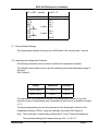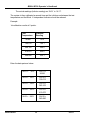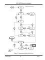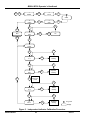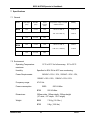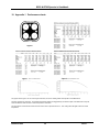
1
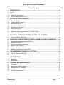
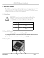
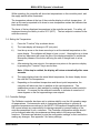
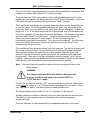
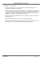
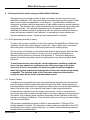
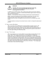
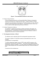
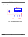
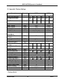
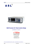
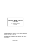
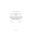
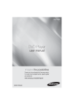
B550 & B700
Operators Manual
Isotech North America
158 Brentwood Drive, Unit 4
Colchester, VT 05446
Phone: (802) 863-8050
Fax:
(802) 863-8050
Email: [email protected]
Web: www.isotechna.com
B550 & B700 Operator’s Handbook
Table of Contents
1.
INTRODUCTION................................................................................................................. 3
2.
SAFETY .............................................................................................................................. 3
2.2
2.3
3.
3.1
3.2
3.3
3.4
3.5
3.6
3.7
3.8
3.9
4.
4.1
5.
5.1
5.2
5.3
5.4
5.5
5.6
6.
6.1
6.2
7.
7.1
7.2
8.
8.1
8.2
8.3
8.4
8.5
REMOVING THE INSERTS ..................................................................................................... 4
OVER TEMPERATURE CUT OUT ............................................................................................ 5
SETTING UP THE CALIBRATOR...................................................................................... 6
GETTING STARTED ............................................................................................................. 6
POWER ON/OFF SWITCH ................................................................................................... 6
OPERATING MODE ............................................................................................................. 6
SETTING THE TEMPERATURE ............................................................................................... 8
CONTROLLER SETTINGS ..................................................................................................... 8
PRE-TUNE FACILITY ......................................................................................................... 10
SELF-TUNE FACILITY ........................................................................................................ 10
CHANGING FROM CENTIGRADE TO FAHRENHEIT MODE......................................................... 10
CHANGING TO 0.1°C RESOLUTION .................................................................................... 12
THE SERIAL INTERFACE FOR THE CONTROLLER (IF FITTED) ................................ 13
FACTORY DEFAULT SETTINGS ........................................................................................... 13
ACHIEVING THE BEST RESULTS USING YOUR METAL BLOCK CALIBRATOR....... 14
PROBE POSITIONING AND USE OF INSERTS .......................................................................... 14
THERMAL CONTACT ......................................................................................................... 14
USE OF CUSTOM DRILLED BLOCKS ..................................................................................... 15
USE OF "TWIN" INSERTS ................................................................................................... 15
SUPPLY VOLTAGE VARIATIONS .......................................................................................... 16
AMBIENT TEMPERATURE VARIATIONS ................................................................................ 16
THE INDEPENDENT INDICATOR (IF FITTED) .............................................................. 16
FACTORY DEFAULT SETTINGS ........................................................................................... 17
LINEARISING THE INDEPENDENT INDICATOR ........................................................................ 17
SPECIFICATIONS ............................................................................................................ 21
GENERAL ........................................................................................................................ 21
ENVIRONMENT ................................................................................................................. 21
CLEANING AND MAINTAINANCE .................................................................................. 22
CLEANING ....................................................................................................................... 22
PREVENTATIVE MAINTENANCE .......................................................................................... 22
GENERAL SAFETY WARNING ............................................................................................. 22
INTERNAL FUSE REPLACEMENT .......................................................................................... 22
PERIODIC MAINTENANCE .................................................................................................. 23
B550-14-002
1
Issue 7
B550 & B700 Operator’s Handbook
9.
9.1
9.2
9.3
9.4
SERVICE AND WARRANTY............................................................................................ 23
TECHNICAL SUPPORT ....................................................................................................... 23
RETURNED INSTRUMENTS................................................................................................. 23
DOCUMENTATION............................................................................................................. 23
REPAIR QUOTATIONS ....................................................................................................... 24
10. APPENDIX 1 PERFORMANCE CHARTS...................................................................... 25
11. APPENDIX 2 WIRING CONNECTIONS FOR DIN CONNECTOR ................................. 26
12. APPENDIX 3 FACTORY SETTINGS ............................................................................... 27
B550-14-002
2
Issue 7
B550 & B700 Operator’s Handbook
1. Introduction
Automatic Systems Laboratories would like to thank you for purchasing this B series
Metal Block Calibrator. The Calibrator is supplied in a fully operational state, but ASL
strongly suggest that these brief operating instructions and guidelines be read before
starting to use the apparatus. Should you have any difficulty understanding the
instructions, or other questions regarding this Calibrator, please call our Customer
Support Group.
2. Safety
WARNING This apparatus is capable of reaching up to 700 °C
in normal operation. Burns to the skin can result through
careless or negligent use. The calibrator has been configured at
ASL, only change the configuration settings after reference to
this handbook. Please follow the guidelines below as a
minimum procedure for safe operation.
i)
Always handle the Calibrator as if the block is hot. Do not touch the top surface
of the block.
ii)
Position the Calibrator in such a way that it cannot be accidentally knocked from
the bench.
Pay careful attention to the positioning of the mains lead to avoid tripping.
iii)
Do not cover the Calibrator at any time, or leave flammable material close to the
Calibrator.
iv)
When removing hot probes from the block, always place them away from
flammable material and make sure that they will not be accidentally touched by
anyone.
v)
Keep all types of liquids away from the Calibrator when in operation.
B550-14-002
3
Issue 7
B550 & B700 Operator’s Handbook
Figure 1. Model B550 with Independent Indicator
vi)
Do not use any liquid in the probe holes of the block. (The use of a few drops of
demineralised water to improve probe/block contact when calibrating below 70°C
(94°F) is permissible with great care. Do not introduce water into the Calibrator
unless the block is cold, and the supply is disconnected. Drain the water by
inverting the Calibrator after use. Do not boil off remaining water. Care should be
taken to avoid any hot inserts falling out of the inverted block.)
vii)
The Calibrator may be switched off and disconnected from the supply without
harm even when at maximum temperature. However, the cooling of the block
will take considerably longer if this is done, and no temperature indication will be
present to warn others that the block may still be hot. The block will take several
hours to cool to ambient temperature if the fan is left running (approximately 5
hours to cool to ambient temperature from
550°C / 1022°F).
viii)
If any part of the Calibrator except the block should become hot during use,
suspend the operation and disconnect the supply.
2.2 Removing the inserts
i)
Use the wire tool to lift the insert. Only lift the insert to a level where you can
hold it using the pliers. Do not try to completely remove the insert using the
wire tool. The wire tool does not provide enough control to allow it to be used to
carry the insert.
ii)
Using the pliers, lift the insert clear of the block and put it in a safe place.
B550-14-002
4
Issue 7
B550 & B700 Operator’s Handbook
2.3 Over temperature cut out
ASL Metal Block Calibrators are fitted two independent over temperature cut outs which
are operated by:
a) Excessive block temperature
b) Fan failure
To reset the calibrator press the start switch. If the light does not go out the fault
condition still exists.
Allow the calibrator to cool before retrying.
WARNING
DO NOT hold your finger on the start switch for more than a few
seconds.
Pressing the start switch resets the thermal trip circuit and may
apply power to the heater.
If the cut out activates repeatedly check the controller settings, if these are correct the
calibrator has a fault. DO NOT USE the calibrator until the fault condition has been
removed.
See Section 8.5 for periodic maintenance.
B550-14-002
5
Issue 7
B550 & B700 Operator’s Handbook
3. Setting up the Calibrator
The Calibrator is designed to give the best performance when operated in a constant
temperature environment without draughts. The calibrator should therefore be
positioned away from air conditioners and direct sunlight. Please read Section 5 of this
manual to achieve the best results from the Calibrator.
3.1 Getting Started
WARNING: Ensure the correct line voltage fuse is fitted before
turning on. Plug in the mains lead and turn on the calibrator
using the green switch marked supply on the top panel. The
cooling fan will start and the controller will start its self check
procedure.
Voltage
Fuse
230V
F3.15A 250VAC (3.15 Amp Quick
blow)
115V
F6.3A
250VAC (6.3 Amp Quick
blow)
3.2 Power ON/OFF switch
I = Power ON
O = Power OFF
The power switch itself will be illuminated (green), when the Block Calibrator power is
switched ON.
Care should be taken not to limit access to the power ON/OFF switch.
3.3 Operating Mode
B550-14-002
6
Issue 7
B550 & B700 Operator’s Handbook
Auto/Manual Key
Low Key
High Key
Function Key
Figure 2. The Controller keys
B550-14-002
7
Issue 7
B550 & B700 Operator’s Handbook
Whilst operating, the controller will show two temperatures on the controller panel, and
the supply switch will be illuminated.
The temperature shown at the top of the controller display is a block temperature. At
start up this can be expected to be close to room temperature unless the calibrator has
been used recently.
The lower of the two displayed temperatures is the controller set point. For safety, all
equipment leaving the factory is set to 20°C (68°F). The last setpoint is retained in the
controller memory.
3.4 Setting the Temperature
i)
Press the "Function" Key as shown above.
ii)
The lower display will change to SP (set point).
iii)
Use the up arrow or the down arrow keys to set the desired temperature on the
upper display. The calibrator will begin to heat, or cool. Keeping the up or down
arrow key depressed will cause the rate of the displayed setpoint to accelerate.
Momentary release of the button will bring the rate of change back to a low
speed.
iv)
After entering the new set point, the operator may return to the previous display
by pressing the "Function" Key a second time.
Note: if this step is omitted, the display will return automatically after some
seconds.
v)
The upper display shows the actual block temperature, the lower display shows
the new Set Point temperature.
vi)
Depending on the ambient temperature and the set point temperature, the
controller will take some time to stabilise at the new temperature. The
stabilisation process is best watched by reading the reference probe inserted in
the block. It is normal for the calibrator controller to indicate an overshoot of
some degrees on the first approaching a new setpoint.
3.5 Controller Settings
The Calibrator controller has been set to optimise stability over the full operating range
of temperatures. Customers who wish to customise these settings to optimise a
particular temperature are referred to the WEST 6100 handbook supplied with the unit.
ASL cannot accept any responsibility for damage caused by incorrect setting of the
controller parameters by our customers. The Controller configuration settings should
not be changed under any circumstances as these relate to the range and alarm
functions. Customers are advised to note the configuration settings on their unit before
making any changes. See appendix 3 for factory settings.
B550-14-002
8
Issue 7
B550 & B700 Operator’s Handbook
The controller can be set to tune its own P.I.D parameters. This is not normally
necessary except when a greatly varying load (high thermal loss to the block) occurs
and the temperature stability of the block is affected.
B550-14-002
9
Issue 7
B550 & B700 Operator’s Handbook
There are two methods of tuning. Pre-tuning and self tuning, although the latter is not
recommended as it can affect the stability at the resolution we are looking for:3.6 Pre-Tune Facility
Pre-Tune may be activated as follows:i)
With the Controller showing its normal Operator Mode display, depress and hold
down simultaneously the Up and Down keys (whereupon the numeric displays
will start to flash) until AT indicator blinks once (after approximately three
seconds - numeric displays will become static).
ii)
Release the Up and Down keys and depress and hold down the "Scroll" key for
three seconds (approximately). If the process variable is greater that 5% of input
span from the setpoint, the AT indicator will then flash, indicating that the PreTune facility is engaged and operating.
If the process variable is within 5% of input span from the setpoint, or if an
erroneous key sequence is used, the Pre-Tune facility will not be engaged.
To disengage the Pre-Tune facility:iii)
Depress and hold down simultaneously the Up and Down keys (whereupon the
numeric displays will start to flash) until the AT indicator blinks once (after
approximately three seconds - numeric displays will become static).
iv)
Release the Up and Down keys and depress and hold down the "Scroll" Key for
three seconds (approximately). The AT indicator will then be continuously OFF,
indicating that the Pre-Tune facility is disengaged.
Note: Since the Pre-Tune facility is a single-shot operation, it will automatically
disengage itself once the operation is complete.
3.7 Self-Tune Facility
The self tune facility as opposed to the pre-tune method can be set on at anytime and
will attempt to modify the terms whilst controlling. We don't recommend that this feature
is left on permanently because it can affect the stability at the resolution we are looking
for.
The self tune facility is invoked by pressing and holding both up and down keys
simultaneously until the AT light blinks once. Then release the keys and press the
"hand" symbol key. The AT light will then illuminate permanently to show that self
tuning is in progress. To cancel, the same procedure is employed.
Note: The Self-Tune facility will not engage if the setpoint is currently ramping.
3.8 Changing from Centigrade to Fahrenheit mode
The Calibrator can operate in Centigrade or Fahrenheit mode.
B550-14-002
10
Issue 7
B550 & B700 Operator’s Handbook
Firstly the controller parameters need to be noted if they are different to the default ASL
settings (for example where different P.I.D terms are used).
To do this enter the "LOC" code (default 8 set by ASL)by pressing the "scroll" button
and the up arrow together, the display will show "ULOC" in the lower section. Enter the
LOC code using the up and down arrows and press "scroll" to accept.
The controller will now display the operating parameters which can be scrolled through
to note the values. Do this by repeatedly pressing the "scroll" key, when back at the
start press "scroll" and up together to exit, and the set LED will extinguish. To Alter the
range from °C to °F, the input range code has to be changed, a list of these codes can
be found in Appendix A of the West Instruments Site Manual. The relevant range codes
are listed under the title "For RTD Inputs". The default codes for units leaving the
factory are given in Appendix 3 of this manual. To enter the new range the
configuration mode has to be accessed. To do this turn the power off. Turn the power
back on and within 30 seconds of power-up, hold down the up and "scroll" keys
simultaneously for five seconds.
The controller will then show the current input code selected. This can be changed with
the up and down arrow keys. As soon as the value is changed the upper display will
flash indicating that the new value has yet to be confirmed, when the value is as
required it may be confirmed by pressing the "hand" key, whereupon the display will
become static. Next return from the configuration mode by pressing "scroll" and up
together. Having returned the display will show the temperature, but with all the decimal
points showing, indicating that the controller parameters need resetting.
Note: If the input code is changed the values in the set-up mode will return to the
default values.
WARNING
The setpoint maximum (SPhi) will default to the upper limit
of range, as will the high alarm, this would be 800°C or
1472°F with the 1° range.
To enter the set-up mode use the "LOC" code as above and re-enter the values noted
down except the values in °C or °F which will need changing to the new scale. This is
very important for safety. The alarm values will need particular care.
The default values can be found for °C or °F in Appendix 3 of this manual.
Another precaution would be to indicate on the front panel that the units are now set to
Fahrenheit in case someone assumes Centigrade and sets the temperature
dangerously high.
The block calibrator is further protected by an independent thermal cut out circuit.
B550-14-002
11
Issue 7
B550 & B700 Operator’s Handbook
3.9 Changing to 0.1°C Resolution
Operation to Change from 1°C resolution (700°C maximum temperature) to 0.1°C
resolution (537°C maximum temperature).
This is an operation virtually identical to changing from Centigrade to Fahrenheit where
a new range of temperature measurement is chosen. See Appendix 3 for the 4 ranges
suitable for the Calibrator. The controller parameters are cleared when the range is
changed, so if one range can be fixed upon all the better.
The code number for the Ambient to 537°C (0.1°C) range is 7222, the 1°C resolution
range code is 7220.
Now follow the procedure in section 4.9 to set in the new range code.
Note: The range code 7220 invokes a range with the controller of 0 to 800°C. It is for
this reason the P.I.D terms will change with this increased input range.
B550-14-002
12
Issue 7
B550 & B700 Operator’s Handbook
4.
The Serial Interface for the controller (if fitted)
The controller may be optionally fitted with an RS232 or an RS485 interface. Refer to
the WEST 6100 controller manual for instructions on using the RS232/RS485.
Connections for the interfaces are:
RS485
“A” or XMT + terminal
“B” or XMT - terminal
RS232
25 Way ‘D’ type socket
Pin 2
Pin 15
25 Way ‘D’ type socket
Pin 5
Pin 3
Pin 2
Pin 20
Pin 7
Pin 6
CTS
RxD
TxD
DTR
GND
DSR
4.1 Factory Default Settings
RS232:
Factory set to 4800 baud, even parity, 7 data bits and 1 stop bit.
RS485:
As above, Address 1.
B550-14-002
13
Issue 7
B550 & B700 Operator’s Handbook
5. Achieving the best results using your Metal Block Calibrator
This section of your manual is written to help you achieve the best results from your
Metal Block Calibrator. ASL has tested this product extensively and the results of these
tests can be found in the appendices of this manual. Your Metal Block Calibrator is
designed to provide a reference temperature of high stability under the correct operating
conditions. The absolute value of this temperature must be measured using a reference
temperature probe. The indicated temperature on the temperature controller is not
calibrated and cannot be used as a reference. ASL can provide a calibrated reference
probe and indicator installed in the Calibrator, or alternatively a more versatile and
accurate standalone system. Please ask your representative for details.
5.1 Probe positioning and use of inserts
To ensure the connect orientation of twin holes inserts in the Metal Block Calibrator the
Calibrator is fitted with location spigots in each well. When fitting inserts, ensure that
the locating hole in the bottom of the insert mates with the locating spigot.
The top surface of the block is not insulated and therefore has a greater heat loss than
the sides and bottom of the block. This gives rise to a variation in temperature at
different vertical positions in the block. (see Appendix 1). The block is designed to
achieve the minimum possible variation in temperature at any horizontal plane within
the block.
To avoid inaccuracies caused by the vertical temperature variations explained
above, the user should use a reference probe of the same type as the probe
under test. If this is not possible, the reference probe should be designed to
match the physical and thermal characteristics of the probe under test as closely
as possible. The insertion depth of the Test probe measure point should be
exactly the same as the reference probe measure point.
5.2 Thermal Contact
To achieve the best possible accuracy, all probes that are inserted in the block should
have the largest possible contact area with the metal of the block. Users operating at
low temperatures may benefit from improving contact by the use of a little demineralized
water in the block holes. In this case the few drops of water required should be
introduced into a cold block with the supply disconnected. Under no circumstances
should any other fluid be used as this will cause a build up of residue and may present a
fire hazard. Any remaining water should be removed from the Calibrator at the end of
the test by inverting the Calibrator. Care should be taken to avoid any hot inserts falling
out of the inverted block.
ASL provide a standard block which is drilled to accommodate 4 T100 type PRTs
directly inserted in the block. The dimensions of these holes are optimised for the T100,
and should not be used for other probe types. A further 4 Inserts (see below) are also
provided with the standard block.
B550-14-002
14
Issue 7
B550 & B700 Operator’s Handbook
WARNING:
Insertion of the incorrect probe type into these holes may
result in inaccurate measurements and/or the probe
becoming stuck in the block.
In addition to the predrilled holes, ASL provides inserts which can be factory drilled to
order, or drilled by our customers to accommodate different types of probe. As may be
seen from the test results in
Appendix 1, the temperature difference between inserts may be several tenths of a
degree. As previously observed for the probe/block contact area, the contact area
between the insert and the block may vary, and the inclusion of a second
metal/air/metal boundary will degrade the accuracy that can be obtained when using
inserts.
To obtain maximum accuracy, the customer has two routes to solving this measurement
problem.
5.3 Use of custom drilled blocks
ASL can provide custom drilled blocks to accommodate most types of probe. This
method insures the minimum number of metal/air/metal boundaries between the
reference probe and the probes under test, and is ideal for the customer who wishes to
qualify multiple probes simultaneously. (Remembering that the probes should all be of
the same type including the Reference probe).
5.4 Use of "Twin" Inserts
ASL recommends the use of inserts drilled to accommodate 2 probes within the same
insert. These "Twin" inserts may be factory or customer drilled, and allow the
qualification of up to 4 different probe types in one calibration run. (Each insert must
contain one reference probe and one probe under test.). ASL is happy to provide blank
inserts for our customers to drill themselves. Due to the possibility of inserts becoming
stuck in the block if incorrectly sized, we recommend the use of factory supplied blanks,
Twin inserts should be placed in the block as shown in the Fig.3 in order to ensure that
the probes under test are equi-distant from the centre of the block. The locating spigot
at the bottom of the well will then engage.
B550-14-002
15
Issue 7
B550 & B700 Operator’s Handbook
Figure 3. Recommended orientation for twin inserts.
5.5 Supply Voltage Variations
As with all electrical equipment, your B series Metal Block Calibrator is designed to
operate most efficiently on a stable electrical supply. Transient variations in supply
voltage will vary the quantity of heat output by the Heating element, and may adversely
affect the temperature stability of the Calibrator. Users should therefore make every
effort to ensure a stable supply during testing and calibration.
5.6 Ambient Temperature Variations
The Calibrator is unaffected by changes in ambient temperature taking place over
several hours. Sudden temperature changes will cause a temporary disturbance in
block temperature. For best results, we recommend that the Calibrator is used in a
draught free environment of constant temperature.
6. The Independent Indicator (if fitted)
The calibrator may be optionally fitted with an independent temperature monitor.
The monitor is linked to a 5 way DIN connector and terminal block on front of the
controller
(see Appendix 2 for wiring details).
To use the independent monitor connect a PRT to either the DIN connector or the
terminal block, insert the PRT into the block. The monitor will now display the block
temperature in degrees Centigrade. If you have ordered an Independent Indicator to be
set up in thermocouple mode, then a thermocouple needs to be connected instead of a
PRT.
Connections for the interfaces are:
RS485
“A” or XMT + terminal
B550-14-002
16
25 Way ‘D’ type socket
Pin 2
Issue 7
B550 & B700 Operator’s Handbook
“B” or XMT - terminal
RS232
TxD
RxD
GND
CTS
internally
RTS
DSR
internally
DTR
Pins 14, 15
25 Way ‘D’ type socket
Pin 2
Pin 3
Pin 7
Linked Pin 5
Pin 4
Linked Pin 6
Pin 20
6.1 Factory Default Settings
The Independent Indicator is factory set to 9600 baud, 8 bit, no parity and 1 stop bit.
6.2 Linearising the Independent Indicator
The following instructions tell you how to linearise the Independent Indicator.
The Indicator must initially be set to suit the reference probe and temperature range of
the block
(See Figure 4)
Range
Resolution
Accuracy
-200 to +850°C
0.1°C
± 0.5°C
-60 to +130°C
0.02°C
± 0.5°C
The reference Pt100 probe and block has to be calibrated as a system to give the
required number of ‘temperature pairs’ (expected and actual),up to a maximum number
of 17.
The above temperature pairs are then entered into the ‘linearisation’ feature of the
independent indicator (CSLin), using the calibration procedure (See Figure 5)
Note: The setup menu is selected by pressing the AL1 and F1 keys simultaneously.
The expected readings (test temperature) are ‘OU 1’ to ‘OU 17’.
B550-14-002
17
Issue 7
B550 & B700 Operator’s Handbook
The actual readings (Indictor reading) are ‘IN 01’ to ‘IN 17’.
The system is then calibrated a second time and the initial errors between the test
temperature and the Block -II Independent Indicator should be reduced.
Example:
1st calibration results at 5 points:
Test
Temperature
Indicator
Reading
49.861
50.2
100.012
100.1
249.102
249.2
419.875
420.2
549.890
550.1
Enter the data pairs as below:
IN 01 =
B550-14-002
50.2
OU 01 =
49.861
IN 02 = 100.1
OU 02 =
100.012
IN 03 = 249.2
OU 03 =
249.102
IN 04 = 420.2
OU 04 =
419.875
IN 05 = 550.1
OU 05 =
549.890
18
Issue 7
B550 & B700 Operator’s Handbook
AL1
1
SEtUP
F1
B550/700 Set-up Procedure
F2
2
InPUt
AL1
8
To next
section of
menu
F1
F2
3
tHEr
F2
F2
select
AL1
4
Type
F2
5
Pt100
F1
F1
F2
select
6
dEG
F2
7
0.1C
F1
End
AL1
9
dISPL
AL1
F2
F2
F1
10
dECPO
F2
11
1.9.9.9.9
select
dp
1999.9
Key press
Display
Figure 4. Independent Indicator initial set up.
B550-14-002
19
Issue 7
B550 & B700 Operator’s Handbook
AL1
F1
1
SEtUP
2
InPUt
F2
F1
3
dISPL
5
CSLIn
4
AdC
F1
F1
F2
F2
AL1
End
7
FUn
F2
On
F1
AL1
F1
9
POInt
F2
F2
10
In 1
F2
F1
F2
11
OU 1
AL1
F1
Actual
reading
F2
Expected
reading
to required
amount of
points
F2
12
In 17
F2
F1
Actual
reading
F2
13
OU 17
F2
Expected
reading
Key press
Display
Figure 5. Independent Indicator Calibration Procedure.
B550-14-002
20
Issue 7
B550 & B700 Operator’s Handbook
7. Specifications
7.1 General
Model
Well Depth
(mm)
Well Dia.
(mm)
Insert
Length
(mm)
Temperature range in normal
ambient of 22 °C
Stability
B550
155
2 x 19
150
+35 °C to +550 °C
±0.05 °C
+95 °F to +1022 °F)
±0.09 °F
+50 °C to +700 °C
±0.05°C
+122 °F to +1292 °F)
±0.09°F
B700
150
4 x 6.35
N/A
155
2 x 18
150
150
4 x 6.35
N/A
7.2 Environment
Operating Temperature:
maximum.
Humidity:
15°C to 25°C for full accuracy, 0°C to 50°C
Specified to 90% RH at 40°C non-condensing.
Power Requirements:
240VAC +10% /-15%, 220VAC +10% /-15%,
120VAC +10% /-15%, 100VAC +10% /-15%
Frequency range:
47-63 Hz.
Power consumption:
B550
B700
550 VA Max.
550 VA Max.
Dimensions:
305mm wide, 165mm depth, 325mm height
(12” wide, 6.5” depth, 12.8” height)
Weight:
B550
7.5 Kg ( 16.5 lbs )
B700
9 Kg ( 19.8 Ibs)
B550-14-002
21
Issue 7
B550 & B700 Operator’s Handbook
8. Cleaning and Maintainance
8.1 Cleaning
Make sure the Block Calibrator is turned off and unplug the mains supply cable.
Clean the outside of the instrument with a soft, clean cloth dampened with mild
detergent. Do not allow water to enter the instrument.
WARNING Never use alcohol or thinners as these will damage the
instrument.
Never use a hard or abrasive brush.
8.2 Preventative Maintenance
WARNING Regular inspection of the mains supply cable is required
to ensure that
the insulation is not damaged.
8.3 General safety Warning
WARNING If the Block Calibrator is used in a manner not specified
by ASL, then
the protection provided by the instrument may be
impaired.
8.4 Internal fuse replacement
WARNING The RS232 to RS485 converter (if fitted) is protected by
an internal fuse.
It is recommended that this is replaced by a competent
ASL trained
technician.
Fuse type:
B550-14-002
T200mA (250 VAC)
(200mA slow blow)
22
Issue 7
B550 & B700 Operator’s Handbook
8.5 Periodic Maintenance
WARNING The block calibrator should be checked every 2 years to
have the safety
cut out tested.
Consult your
ASL offer a comprehensive service for all its products.
distributor for details.
Alternatively, a technical procedure for verifying
operation of the cutout
is available from ASL’s customer
support group. This operation should
only be carried out
by a suitably qualified engineer.
9. Service and Warranty
Block Bath equipment and accessories, (unless stated otherwise), are covered by a 12
month warranty for parts and labor, but not including costs incurred in returning it to the
factory for repair, from the date of dispatch from Automatic Systems Laboratories.
9.1 Technical Support
For all technical support, repair, warranty and service inquiries please contact:
ASL Inc.,
Druck Incorporated
4 Dunham Drive
Fairfield
CT 06812
USA
Telephone:
Fax:
E-Mail
Web page:
978 658 0000
978 658 5444
[email protected]
www.aslinc.com
9.2 Returned Instruments
All returned goods should be sent carriage paid, insured and packed well, to the above
address.
9.3 Documentation
The shipment should include:
i)
Your goods return note, a delivery note or an export invoice stating clearly
GOODS RETURNED FOR REPAIR.
ii)
Your Company / Establishment order or contract reference number.
B550-14-002
23
Issue 7
B550 & B700 Operator’s Handbook
iii)
The name of your purchasing and technical contact.
iv)
A brief fault report.
9.4 Repair Quotations
We shall be pleased to advise estimated repair costs upon receipt and initial inspection
of returned goods.
B550-14-002
24
Issue 7
B550 & B700 Operator’s Handbook
10. Appendix 1 Performance charts
The graphs above, Figure 7 at 125°C and Figure 8 at 200°C, show the vertical gradient of temperature in the B550 block.
The PRT used was the T100-250. The resulting temperature gradient is exaggerated by the insertion depth of the PRT itself to the point
where the detector within the PRT is near the top surface of the block.
The stem losses of the PRT will increase as more surface area is expossed to the air. This cooling affect will again reduce the actual
temperature.
B550-14-002
25
Issue 7
B550 & B700 Operator’s Handbook
11. Appendix 2 Wiring connections for DIN connector
Figure 9. Wiring Diagram for Independent Indicator.
B550-14-002
26
Issue 7
B550 & B700 Operator’s Handbook
12. Appendix 3 Factory Settings
Description
Paramete
r
RESOLUTION REQUIRED
Configuration Mode
1
Deg
C
7220*
Setup Mode
Digital Filter Time
Constant
Process Variable Offset
Output Power
Proportional Band 1
Rate Integral Time
Constant
Rate Derivative Time
Constant
Manual Rest Bias
Set Point High Limit
Set Point Low Limit
Output 1 Power Limit
Output Cycle Time
Process Low Alarm 1
Process High Alarm 2
Loop Alarm Enable
Auto Pre Tune Enable
Manual Control Enable
Setpoint Ramp Enable
Setpoint Strategy
Communications Enable
Lock value
Ctrl
ALA1
ALA2
Inhi
USE2
Loc
rEU
P-Lo
P-hi
nonE
Or-r
8 (Initially 10)
Filt
0
0
OFFS
Out1
Pb1
rSEt
0.32
0
Fixed
1
0.46
0.32
0.46
0
Fixed
1
0.32
0.32
rAtE
0.08
0.11
0.11
0.08
biAS
SPhi
SPlo
OPhi
Ctl
l-A1
h-A2
LAEn
Apt
PoEn
rPEn
SPSt
CoEn
Loc
0.1
Deg
C
7222
1
Deg
F
7221
B700
1
1
Deg
Deg
C
F
7220 7221
*
rEU
P-Lo
P-hi
nonE
Or-r
8 (10)
Input Code
Output 1 Action
Alarm 1 Action
Alarm 2 Action
Alarm Inhibit
Output 2 Usage
Lock Code
B550
0.08
0.1
Deg
F
7223
25
550
25
532
1022 989
32
0
100
0.5
0
555
537
0.08
32
1031 999
0
0
0
0
1
0 (1 if RS485 fitted)
8
700
0
1292
32
100
0.5
0
32
705
1301
0
0
0
0
1
0 or 1 A/R
8
* Factory default
B550-14-002
27
Issue 7
B550 & B700 Operator’s Handbook
WARNING
Read section 3.5 before altering the controller’s parameters, in
particular the setpoint limits. Exceeding the maximum
temperature may cause permanent damage.
B550-14-002
28
Issue 7
B550 & B700 Operator’s Handbook
NOTES
B550-14-002
29
Issue 7