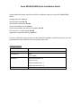
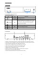
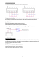
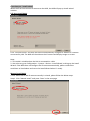
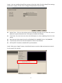
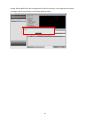
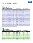
1
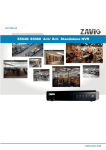
S5040/S5080 0 8608552000010 Zavio S5040/S5080 Quick Installation Guide Please follow the below instruction and the installation steps to set up your S5040/S5080 SNVR. Package Contents. See P.1 Physical Overview. See P.2 LED Indicator Definition. See P.2 I/O Terminal Block Circuit. See P.3 Install the hardware and connect all cables. See P.4 First-time use – install wizard. See P.6 Appendix: Compatible HDD list. See P.12 For more information, please check the User Manual available in the Software CD or you can download the latest software from http://www.zavio.com Package Contents Device S5040/S5080 Standalone Network Video Recorder Quick Installation Guide Brief product information and quick installation Software CD CMS User manual Accessory Alarm terminal block x 4 Rubber foot x 4 HDD mounting screw x 4 VGA connector screw x 2 Adaptor & Power Cord 12V, 5A 1 Physical Overview a. Front Panel 3 1. Power button: Power On/Off NVR 2. LED Indicator Definition LED Power 2 Color 1 Indication Flash Blue Booting up process Steady Blue Booting up competition System exception alert is detected, such as disk Warning full, disk error, no disk, network disconnect, illegal Red login, disk over temperature, fan fail, network fail, power loss and IP conflict. HD Blue System is accessing hard disk LAN Blue NVR is connecting to LAN port WAN Blue NVR is connecting to WAN port 3. USB port : USB port for connecting devices, such as USB mouse or USB flash device. b. Rear Panel 7 1 2 3 4 5 6 8 9 10 1. Audio In: Connect the microphone or camera audio output to the audio input connector. 2. Audio Out: Connect a speaker or other audio output device to the audio output connector. 3. VGA: Connect a VGA monitor to the VGA output connector. 4. HDMI: Connect a HDMI monitor to the HDMI output connector. 5. LAN: Connect hub with IP cameras via RJ-45 network cable. 6. WAN: Connect NVR to Internet via a RJ-45 network cable. 7. RS485 socket: For RS485 PTZ control. 8. Alarm In: Connect to 4 or 8 alarm inputs to the alarm input connectors. 9. Alarm Out: N.C or N.O type alarm signal out. 10. Power: Plug the DC12V power source into the power socket. 2 I/O Terminal Block Circuit The alarm input/output interface of the NVR is shown below. Connect the alarm inputs Configure the alarm inputs as N/O or N/C in the NVR UI system. Each (alarm) input line can be switched by a contact from external devices. Wire them as either Normally Open or Normally Closed. Specifications Alarm input impedance: Internal pull-up 10 K to +5 V Input voltage range: 0 VDC minimum to 12 VDC maximum Input voltage threshold: low voltage 0.5 V maximum, high voltage 2 V minimum Connect the alarm outputs Configure the alarm outputs as N/O or N/C in the NVR UI system. The 2 alarm output relays are responding to input alarms and triggers. Do not exceed 24 Vdc, 500 mA (continuous), or 10 VA on an alarm output relay's contacts. Specifications Switching current (resistive): 500 mA maximum Switching voltage (resistive): 24 VDC maximum Cable cross section: AWG 26-16 (0.13-1.5 mm2) 3 Install the HDD and connect all cables 1. Remove all the screws on the rear panel. 2. Slide out the top cover. 3.Slide in HDD. 4. Use the screws attached in accessory to mount HDD with the bracket. 5. Connect SATA connection cable & SATA power cable to HDD. For easier installing HDD, you may cut off the cable ties and connect SATA cables to the HDD number 1 first and then connect to the HDD number 2. 6. Slide in the top cover. 7. Fasten screws on the rear panel. VGA screws are attached in the accessory. Please fasten VGA screws before connecting the monitor to the VGA output 4 Connections: Note: 1. Monitor: Supporting display mode from 1024x768 up to 1920x1080 2. RS-485: Connect a pan/tilt/zoom control unit to the RS-485 port through the supplied terminal block. 5 First-time use – install wizard When the first time connect IP cameras to the NVR, the NVR will pop up install wizard window. Full Auto Install Mode Click “Full Auto Install” and then the NVR will automatically configure IP address of a camera connected by LAN. The NVR will then detect the IP camera and display image on screen. Note: 1. This mode is suitable when the LAN is connected to a hub. 2. User also can go to Configuration→System→Device→Install Wizard, to bring up the Install Wizard. If the NVR does not configure the IP camera automatically, please recheck the conditions as listed above and rerun the Install Wizard when it’s ready. Manual Install Mode If user would like to add IP camera manually in wizard, please follow the below steps. Step 1. Click “Manual Install” and press “Next’ to the next page. 6 Step 2. Device setting: Device name: User can change the device name. Language: User can select the desired display language. Enable authentication: User can select enable or not. Keep recorded data in hard disk: User can select to keep or not. After finish the device setting, please click “Next” to the next page. Step 3. User can configure network settings for WAN and LAN. The connection of the LAN port is for IP cameras. The connection of the WAN port is for the NVR to Internet. The NVR provides the options for user to access to the NVR through DHCP, Fixed IP or PPPoE. Select the option user would like to use to enable and configure the settings. When the LAN port of the NVR is connected to IP cameras via a hub, user can choose DHCP or Fixed IP to enable and configure the settings. After finish the network settings, please press “Next” to the next page. 7 Step 4. User can configure Date/Time settings of the NVR. After finish the Date/Time settings, please press “Apply” to save user’s changes and proceed to the next step. Adjust Time : Click on the column and the Calendar will pop up on screen for user to adjust the system date and time. Click Apply to enable the settings. Time Zone: Set the time zone that the NVR adjusts to when updating from the time server. Date Format: Select date format from DD/MM/YYYY, MM/DD/YYYY or YYYY/MM/DD. Time Format: Select time format between 12 Hours and 24 Hours. NTP On/Off: To enable or disable NTP synchronization. Step 5. After press “Apply” button, the NVR will start to scan the LAN environment to search for the specific IP cameras. 8 Step 6. After NVR gets the specific IP cameras, it will display the IP camera list. User can click “Add” button to add IP camera into desired channel. Step 7. After adding IP cameras into NVR, NVR will start to configure the parameters of the IP cameras. 9 Step 8. When NVR finish the configuration of the IP cameras, it will pop up the success message and IP camera also successfully add into NVR. 10 Appendix: Compatible HDD list HDD Manufacturer Model Capacity Seagate SV35 3TB Seagate SV35 2TB Seagate SV35 1TB WD AV-GP 4TB WD AV-GP 3TB WD AV-GP 2TB WD AV-GP 1TB WD WD4000FYYZ 4TB WD WD4000F9YZ 4TB WD WD3000F9YZ 3TB WD WD2000F9YZ 2TB WD WD30EURX 3TB TOSHIBA DT01ACA300 3TB TOSHIBA DT01ACA200 2TB TOSHIBA DT01ACA100 1TB TOSHIBA DT01ACA050 500GB TOSHIBA DT01ABA300V 3TB 11 Memo ………………………………………………………………………………….. ………………………………………………………………………………….. ………………………………………………………………………………….. ………………………………………………………………………………….. ………………………………………………………………………………….. ………………………………………………………………………………….. ………………………………………………………………………………….. ………………………………………………………………………………….. ………………………………………………………………………………….. ………………………………………………………………………………….. ………………………………………………………………………………….. ………………………………………………………………………………….. ………………………………………………………………………………….. ………………………………………………………………………………….. ………………………………………………………………………………….. ………………………………………………………………………………….. ………………………………………………………………………………….. ………………………………………………………………………………….. ………………………………………………………………………………….. ………………………………………………………………………………….. ………………………………………………………………………………….. ………………………………………………………………………………….. ………………………………………………………………………………….. ………………………………………………………………………………….. ………………………………………………………………………………….. 12 Memo ………………………………………………………………………………….. ………………………………………………………………………………….. ………………………………………………………………………………….. ………………………………………………………………………………….. ………………………………………………………………………………….. ………………………………………………………………………………….. ………………………………………………………………………………….. ………………………………………………………………………………….. ………………………………………………………………………………….. ………………………………………………………………………………….. ………………………………………………………………………………….. ………………………………………………………………………………….. ………………………………………………………………………………….. ………………………………………………………………………………….. ………………………………………………………………………………….. ………………………………………………………………………………….. ………………………………………………………………………………….. ………………………………………………………………………………….. ………………………………………………………………………………….. ………………………………………………………………………………….. ………………………………………………………………………………….. ………………………………………………………………………………….. ………………………………………………………………………………….. ………………………………………………………………………………….. ………………………………………………………………………………….. 13 Memo ………………………………………………………………………………….. ………………………………………………………………………………….. ………………………………………………………………………………….. ………………………………………………………………………………….. ………………………………………………………………………………….. ………………………………………………………………………………….. ………………………………………………………………………………….. ………………………………………………………………………………….. ………………………………………………………………………………….. ………………………………………………………………………………….. ………………………………………………………………………………….. ………………………………………………………………………………….. ………………………………………………………………………………….. ………………………………………………………………………………….. ………………………………………………………………………………….. ………………………………………………………………………………….. ………………………………………………………………………………….. ………………………………………………………………………………….. ………………………………………………………………………………….. ………………………………………………………………………………….. ………………………………………………………………………………….. ………………………………………………………………………………….. ………………………………………………………………………………….. ………………………………………………………………………………….. ………………………………………………………………………………….. 14 15