1
Operator's
Manual
CRnJ:rSMRH
2-Cycle
Electric Start Capable
HANDHELD BLOWER / VACUUM
Model No 316.794720
INCREDI.PULLX H
UNBELIEVABLE
STARTING
E A S E
• SAFETY
ASSEMBLY
OPERATION
MAINTENANCE
PARTS LIST
• ESPANOL, R 15
CAUTION: Before using this
product, read this manual and
understand all safety rules and
operating instructions.
Sears Brands
Management
Corporation,
Visit our website:
769-06510
P00
Hoffman
Estates, IL 60179 U.S.A.
www.craftsman.com
05/11
TABLE OF CONTENTS
Rules for Safe Operation .................................................................................
Warranty ..........................................................................................................
Know Your Unit ...............................................................................................
2
4
5
Assembly Instructions .....................................................................................
Oil and Fuel Information ..................................................................................
6
7
Starting/Stopping
Instructions ........................................................................
8
Operating Instructions ....................................................................................
9
Maintenance and Repair Instructions ...........................................................
10
Cleaning and Storage ...................................................................................
11
Speed Start TM Accessory ..............................................................................
11
Troubleshooting Chart ...................................................................................
12
Specifications ...............................................................................................
13
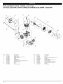
Parts List .......................................................................................................
30
Service Numbers ...........................................................................
Back Cover
The safety symbols, and their explanations, deserve your careful attention
and understanding. The safety warnings do not by themselves eliminate any
The instructions
or warnings
they your
give are
not substitutes
proper
I danger.
The purpose
of safety symbols
is to attract
attention
to possible for
dangers.
accident prevention
SYMBOL
SAFETYis ALERT:
danger,
warning
or caution.
Attention
required in Indicates
order to avoid
serious
personal
injury.
May be used in conjunction with other symbols or pictographs.
NOTE: Advises of information or instructions
maintenance of the equipment.
WARNING:
to yourself and
Failure
obey a
safetythewarning
can result in to
injury
others. to
Always
follow
safety precautions
reduce the risk of fire, electric shock and personal injury.
SPARK ARRESTOR NOTE
,, IMPORTANT
CAUTION:
Failure
to obey injury
a safety
warning or
may
property damage
or personal
to yourself
to result
others.in
Always follow the safety precautions to reduce the risk of fire,
electric shock and personal injury.
Read the Operator's Manual and follow all warnings and safety
instructions. Failure to do so can result in serious injury to the operator
and/or bystanders.
FOR QUESTIONS, CALL 1-800-4-MY-HOME®
SAFETY INSTRUCTIONS
SAFETY WARNINGS
,_
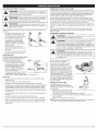
CALIFORNIA PROPOSITION 65
WARNING: Engine exhaust, some of its
constituents and
certain finished components contain or emit chemicals known to
the State of California to cause cancer and birth defects or other
reproductive
harm. Wash hands after handling.
READ ALL INSTRUCTIONS
BEFORE OPERATING
WARNING:
unit, all safety
must be
followed. PleaseWhen
read using
these the
instructions
beforerules
operating
the unit
in order to ensure the safety of the operator and any bystanders.
Please keep these instructions for later use.
carefully. Be familiar with the controls and proper
vital to the operation or
DANGER:
Failure
obey aAlways
safety follow
warningthewill
resultprecautions
in serious
injury
to yourself
or totoothers.
safety
to reduce the risk of fire, electric shock and personal injury.
All information, illustrations, and specifications in this manual are based on the
latest product information available at the time of printing. We reserve the right
to make changes at any time without notice.
NOTE: For users on U.S. Forest Land and in the states of California, Maine,
Oregon and Washington.
All U.S. Forest Land and the state of California
(Public Resources Codes 4442 and 4443), Oregon and Washington require, by
law that certain internal combustion engines operated on forest brush and/or
grass-covered areas be equipped with a spark arrestor, maintained in effective
working order, or the engine be constructed, equipped and maintained for the
prevention of fire. Check with your state or local authorities for regulations
pertaining to these requirements. Failure to follow these requirements could
subject you to liability or a fine. This unit is factory equipped with a spark
arrestor. If it requires replacement, ask your LOCAL SERVICE DEALER to
install the Accessory Part #753=06027 Muffler Assembly
measures.
MEANING
,,
FOR GAS UNITS
WARNING:
Gasoline
is
explode if ignited.
Take the
highly
flammable
and its vapors can
following
precautions:
•
Store fuel only in containers specifically
storage of such materials.
designed and approved for the
•
Always stop the engine and allow it to cool before filling the tank. Never
remove the fuel tank cap or add fuel when the engine is hot. Always
loosen the fuel tank cap slowly to relieve any pressure in the tank before
fueling. DO NOT smoke.
•
Always mix and add fuel in a clean, well-ventilated
there are no sparks or flames. DO NOT smoke.
•
Never operate the unit without the fuel cap securely in place.
•
outdoor area where
•
Read the instructions
use of the unit.
•
Do not operate this unit when tired, ill, or under the influence of alcohol,
drugs, or medication.
Avoid creating a source of ignition for spilled fuel. Wipe up any spilled
fuel from the unit immediately, before starting the unit. Move the unit at
least 30 ft. (9.1 m) from the fueling source and site before starting the
engine. DO NOT smoke.
•
Children and teens under the age of 15 must not use the unit, except for
teens guided by an adult.
Never start or run the unit inside a closed room or building. Breathing exhaust
fumes can kill. Operate this unit only in a well ventilated outdoor area.
•
All guards and safety attachments
operating the unit.
•
Inspect the unit before use. Replace damaged parts. Check for fuel
leaks. Make sure all fasteners are in place and secure. Replace parts that
are cracked, chipped, or damaged in any way. Do not operate the unit
with loose or damaged parts.
must be installed properly before
•
Carefully inspect the area before starting the unit. Remove all debris and
hard or sharp objects such as glass, wire, etc.
•
Clear the area of children, bystanders, and pets. At a minimum, keep all
children, bystanders, and pets outside a 50 feet (15 m) radius; there still
may be a risk to bystanders from thrown objects. Bystanders should be
encouraged to wear eye protection. If you are approached, stop the unit
immediately.
Squeeze the throttle control and check that it returns automatically to the
idle position. Make all adjustments or repairs before using unit.
•
WHILE OPERATING
•
Wear safety glasses or goggles that are marked as meeting ANSI
Z87.1-1989 standards and are marked as such.
•
Never run the unit without the proper equipment attached. Do not
operate the unit without the blower tubes or vacuum tubes and vacuum
bag attached. Make sure the vacuum bag is completely zipped closed.
To reduce the risk of hearing loss associated with sound level(s), always
wear ear/hearing protection when operating this unit.
•
•
Wear heavy long pants, boots, gloves, and a long sleeve shirt. Do not
wear loose clothing, jewelry, short pants, sandals or go barefoot. Secure
hair above shoulder level.
•
Use the unit only in daylight or good artificial light.
•
•
Keep outside surfaces free from oil and fuel.
Avoid accidental starting. Be in the starting position whenever pulling
the starter rope. The operator and unit must be in a stable position while
starting. Refer to Starting/Stopping Instructions.
•
Do not set unit on any surface except a clean, hard area while engine is
running. Debris such as gravel, sand, dust, grass, etc. could be picked
up by the air intake and thrown out by the discharge opening, damaging
unit, property, or causing serious injury to bystanders or operator.
OTHER SAFETY WARNINGS
Use
therighttool.Onlyusethistoolforitsintended
purpose.
Donotforceunit.Itwilldothejobbetter
andwithlesslikelihood
ofinjury
Always disconnect the spark plug before performing maintenance or
atarateforwhich
itwasdesigned.
accessing movable parts.
Donotoverreach
orusefromunstable
surfaces
such
asladders,
trees,
Never store the unit, with fuel in the tank, inside a building where fumes
steep
slopes,
rooftops,
etc.Always
keep
proper
footing
andbalance.
may reach an open flame (pilot lights, etc.) or sparks (switches, electrical
motors, etc.).
Always
holdtheunitwithafirmgripwhen
operating.
Allow the engine to cool before storing or transporting. Be sure to secure
Keep
hands,
face,
andfeetaway
from
allmoving
parts.
Donottouch
or
the unit while transporting.
trytostoptheimpeller
when
itisrotating.
Donotoperate
without
guards
Store the unit in a dry place, either locked up or up high to prevent
inplace.
Donotputanyobject
intoopenings.
Donotusewithanyopening
blocked; unauthorized use or damage. Keep out of the reach of children.
keep
freeofdirt,debris,
andanything
thatmayreduce
theairflow.
Never douse or squirt the unit with water or any other liquid. Keep
handles dry, clean, and free from debris. Clean after each use, see
Donottouch
theengine
ormuffler.
These
parts
getextremely
hotfrom
Cleaning and Storage instructions.
operation,
even
after
theunitisturned
off.
Keep these instructions. Refer to them often and use them to instruct other
Donotoperate
theengine
faster
thanthespeed
needed
todothejob.
users. If you loan this unit to others, also loan these instructions to them.
Donotruntheengine
athighspeed
when
notinuse.
NOTE: Exposure to vibrations through prolonged use of gasoline
Always
stoptheengine
when
operation
isdelayed
orwhen
walking
from SPECIAL
powered hand tools could cause blood vessel or nerve damage in the
onelocation
toanother.
fingers, hands, and joints of people prone to circulation disorders or
Stoptheengine
formaintenance,
repair,
toinstall
orremove
theblower
abnormal swelling. Prolonged use in cold weather has been linked to
tubes
orvacuum
attachments.
Theunitmust
bestopped
andthe
blood vessel damage in otherwise healthy people. If symptoms occur
impeller
nolonger
turning
toavoid
contact
withtherotating
blades.
such as numbness, pain, loss of strength, change in skin color or texture,
Ifyoustrike
orcome
intocontact
withaforeign
object,
stoptheengine
or loss of feeling in the fingers, hands or joints, discontinue use of this
immediately
andcheck
fordamage.
Donotoperate
before
repairing
tool and seek medical attention. An anti-vibration system does not
damage.
Donotoperate
theunitwithloose
ordamaged
parts.
guarantee avoidance of these problems. Users who operate power tools
Useonlygenuine
factory
replacement
parts
andaccessories
forthis
on a regular basis must closely monitor their physical condition and the
condition of this tool.
unit.These
areavailable
fromyourauthorized
service
dealer.
Useofany
unauthorized
parts
oraccessories
could
leadtoserious
injury
totheuser
ordamage
totheunit,andvoidyourwarranty.
Toreduce
firehazard,
replace
faulty
muffler
andspark
arrestor.
Keep
the
engine
andmuffler
freefromgrass,
leaves,
excessive
grease
orcarbon
SAVE THESE INSTRUCTIONS
buildup.
Never
usethisunitforspreading
chemicals,
fertilizers
orother
substances
which
maycontain
toxicmaterials.
Never
point
theblower
inthedirection
ofbystanders,
animals,
windows
orautomobiles.
Avoid
situations
thatcould
catch
thevacuum
bagonfire.Donotoperate
near
anopen
flame.
Donotvacuum
warm
ashfrom
fire-places,
barbecue
pits,brush
piles,
etc.Donotvacuum
discarded
cigars
orcigarettes
unless
thecinders
arecompletely
cool.
•
The unit is designed to pickup dry material such as leaves, grass, small
twigs, and bits of paper. Do not attempt to vacuum wet debris and/or
standing water as this may result in damage to the blower/vacuum. To avoid
severe damage to the impeller, do not vacuum metal, broken glass, etc.
,, SAFETY
& iNTERNATiONAL
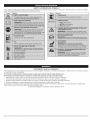
This operator's manual describes safety and international symbols and pictographs
safety, assembly, operating and maintenance and repair information.
SYMBOL
SYMBOLS
that may appear on this product.
MEANING
SYMBOL
CRAFTSMAN
2 YEAR
,,
FULL
This warranty
coverage
details to obtain free repair or replacement,
covers ONLY defects
in material
and workmanship.
manual for complete
MEANING
WARRANTY
FOR 2 YEARS from the date of purchase, this product is warranted against any defects in material or workmanship.
or replacement if repair is unavailable.
For warranty
Read the operator's
A defective product will receive free repair
visit the web site: www.craftsman.com
Warranty
coverage
does NOT include:
•
•
Expendable items that can wear out from normal use within the warranty period, such as air cleaner or spark plug.
Product damage resulting from user attempts at product modification or repair or caused by product accessories.
•
Repairs necessary because of accident or failure to operate or maintain the product according to all supplied instructions.
•
Preventive maintenance, or repairs necessary due to improper fuel mixture, contaminated or stale fuel.
This warranty is void if this product is ever used while providing commercial services or if rented to another person. This warranty gives you specific legal
rights, and you may also have other rights which vary from state to state.
Sears Brands Management
Corporation,
Hoffman Estates, IL 60179
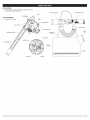
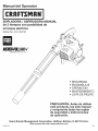
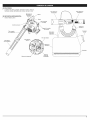
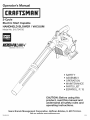
APPLiCATiONS
Cleaning yards, garages, driveways, porches, patios,
around walls, fences and more
Lower Vacuum Tube
On/Off
TOOLS REQUIRED:
Flathead Screwdriver
UpperVaeuum
Tube
Switch
X
Trigger
park Plug Boot
Starter Rope Grip
Cinch
Upper
Blower
Tube
Strap
Vacuum Bag
Strap
Primer Bulb
Air Filter Cover
Lower
Blower
\
Tube
\
Vacuum
Bag_
./ Zipper
.............
Choke
Lever
Fuel
Cap
.._.;:_:;;; ..........................
;_
J
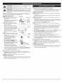
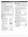
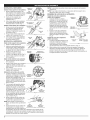
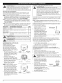
BLOWER ASSEMBLY
InstaUing the Upper Blower Tube
1.
Blower
Outlet
__
Align the bump on the end of the
upper blower tube with the bump
slot on the bottom end of the blower
outlet (Fig. 1).
2.
Insert the upper blower tube into the
blower outlet (Fig. 1).
3.
Twist the upper blower tube clockwise
until it locks into place (Fig. 1).
Installing the Lower Blower Tube
1. Align the bump slot on the top end of
the lower blower tube with the bump
on the end of the upper blower tube
(Fig. 2).
2. Place the lower blower tube onto the
upper blower tube (Fig. 2).
3. Twist the lower blower tube
clockwise until tight (Fig. 2).
1.
2.
3.
4.
the Upper Blower
Tube
2.
3.
2.
While holding the impeller door open,
align the upper vacuum tube's three
(3) slots with the impeller intake's
three (3) lock tabs (Fig. 5). Insert the
upper vacuum tube into the impeller
intake and twist the upper vacuum
tube clockwise with both hands until
the lock tabs snap into place (Fig. 6).
Align the arrow on the lower vacuum
tube with the arrow on the upper
vacuum tube (Fig. 7).
NOTE: The arrows must align properly to
install the vacuum tubes correctly.
4. Grasp the lower vacuum tube firmly
with both hands and push the lower
vacuum tube into the upper vacuum
tube. Turn the lower vacuum tube
clockwise until it snaps into place
and locks. The dot on the lower tube
aligns with the dot on the upper tube
when properly assembled.
NOTE: Use both hands during this
assembly to fit the parts together
tightly.
Lower
Blower
Tube
Bump
\
Bump Slot
Fig. 2
Tube Lock
\
Fig. 3
Impeller
Door
Door
Lock Tab
Fig. 4
impeller
@
Lock Tabs
Fig. 5
Upper
Vacuum
Tube
Fig. 6
Upper
Lower
Vacuum
Vacuum
Tube
Tube
Fig. 7
Elbow onto the
While facing the front of the unit,
hold the keyed end of the vacuum
elbow in your left hand and the flared
end in your right hand. Align the lock
tabs on the keyed end with the lock
tabs on the blower outlet. (Fig. 8)
Insert the vacuum elbow into the
blower and turn clockwise until it
locks into place. (Fig. 8)
Inserting the Vacuum Elbow into the
Bag
1. Locate the small opening in the
vacuum bag. Insert the flared end
of the vacuum elbow approximately
4 inches inside the small opening.
(Fig. 9)
2.
3.
NOTE: The flat area on the upper
vacuum tube should face the handle
when installed correctly.
the Vacuum
Upper Blower
Tube
Grasp the lower blower tube and
twist it counterclockwise
until the
lower blower tube unlocks from the
upper blower tube.
Remove the lower blower tube from
the upper blower tube.
InstalJing the Vacuum Tubes
1. Locate the hole in the impeller door.
The door lock tab is recessed in the
hole toward the front of the blower
(Fig. 4). Insert a flat head screwdriver,
into the hole and press the door lock
tab in and lift the door to release the
lock.
Installing
Blower
2.
Fig. 1
Hold the unit firmly.
Insert a flathead screwdriver into
the tube lock. Twist the screwdriver
counterclockwise
1/4 turn and hold
(Fig. 3).
Grasp the upper blower tube and
twist it counterclockwise
(Fig. 3).
Pull the upper blower tube from the
blower outlet.
Removing the Lower Blower Tube
1. Hold the upper blower tube firmly.
BAG ASSEMBLY
1.
VACUUM ASSEMBLY
Removing
VACUUM
Vacuum_
----,_______/
Elbow
Fig. 8
\
Elbow
Cinch
Strap
(10.2 cm)
Vacuum
Bag
Pull the end of the cinch strap to
Fig. 9
secure the small opening of the bag
around the vacuum elbow. Tighten the cinch strap so that the bag has
limited movement along the elbow, but will not slip off the flared end.
OiL AND FUEL MiXiNG iNSTRUCTiONS
FUELING THE UNiT
CAUTION:
For proper engine operation and maximum
reliability, pay strict attention to the oil and fuel mixing
instructions on the 2-cycle oil container. Using improperly
fuel can severely damage the engine.
mixed
Old and/or improperly mixed fuel are the main reasons for the unit not
running properly. Be sure to use fresh, clean unleaded fuel. Follow the
instructions carefully for the proper fuel/oil mixture.
Definition of Blended Fuels
1.
Remove the fuel cap (Fig. 10).
2.
Place the gas container's spout into
the fill hole on the fuel tank and fill.
NOTE: Do not overfill the tank.
3.
Wipe up any gasoline that may have
4.
spilled. the fuel cap.
Reinstall
5.
Move the unit at least 30 ft. (9.1
m) from the fueling source and site
before starting the engine.
Today's fuels are often a blend of gasoline and oxygenates such as ethanol,
methanol, or MTBE (ether). Alcohol-blended fuel absorbs water. As little as 1%
water in the fuel can make fuel and oil separate. It forms acids when stored.
When using alcohol-blended fuel, use fresh fuel (less than 30 days old).
Using Blended Fuels
If you choose to use a blended fuel, or its use is unavoidable,
recommended precautions:
Always use the fresh fuel mix explained in your operator's
f/)?/_\
S
rig. 1o
WARNING:
NOT
USE E85greater
FUEL
been proven thatDOfuel
containing
iN THIS
It has
than
10%UNIT.
ethanol
will
likely damage this engine and void the warranty.
follow
_:_
manual
Use the fuel additive STA-BIL® or an equivalent
Always agitate the fuel mix before fueling the unit
Drain the tank and run the engine dry before storing the unit
WARNING:
may explode.
Gasoline
extremely
Always
stopis the
engine flammable.
and allow itIgnited
to coolvapors
before
filling the fuel tank. Do not smoke while filling the tank. Keep
sparks and open flames at a distance from the area.
WARNING:
Remove
slowlythetofuel
avoid
from infuel
spray. Never operate
the fuel
unitcap
without
capinjury
securely
place.
Using Fuel Additives
The bottle of 2-cycle oil that came with your unit contains a fuel additive
which will help inhibit corrosion and minimize the formation of gum deposits.
It is recommended that you use our 2-cycle oil with this unit. If unavailable,
use a good 2-cycle oil designed for air-cooled engines along with a fuel
additive, such as STA-BIL® Gas Stabilizer or an equivalent. Add 0.8 oz. (23
ml) of fuel additive per gallon of fuel according to the instructions on the
container. NEVER add fuel additives directly to the unit's fuel tank.
Mixing The Fuel
Thoroughly mix the proper ratio of 2-cycle engine oil with unleaded gasoline
in a separate fuel can. Use a 40:1 fuel/oil ratio. Do not mix them directly in the
engine fuel tank. See the table below for specific gas and oil mixing ratios.
NOTE: One gallon (3.8 liters) of unleaded gasoline mixed with one 3.2 oz.
(95 ml) bottle of 2-cycle oil makes a 40:1 fuel/oil ratio. This unit comes
with a 3.2 oz. bottle of 2-cycle oil. Pour the entire bottle into one gallon of
unleaded gasoline to obtain the proper fuel mixture.
NOTE: Dispose of the old fuel/oil mix in accordance with federal, state and
local regulations.
UNLEADED
GAS*
1 GALLON
US
(3,8 MTERS)
1 MTER
MiXiNG
2-CYCLE
OiL
3,2 FL OZ,
(95 ML)
25 ML
RATIO - 40:1
outdoor area. Wipe up any spilled fuel immediately. Avoid creating
_
a source of ignition for spilled fuel. Do not start the engine until
WARNING:
Add fuel in a clean, level and well ventilated
fuel vapors dissipate.
WARNING:
Operate this unit only in a well-ventilated outdoor
area. Carbon monoxide exhaust fumes can be lethal in a
confined area.
ill
WARNING:
Avoid accidental starting. Make sure to be in the
starting position when pulling the starter rope (Fig. 13). To avoid
serious injury, the operator and unit must be in a stable position
while starting.
NOTE: This unit has the Incredi-Pull TM starting system, which significantly
reduces the effort required to pull the starter rope.
STARTING INSTRUCTIONS
NOTE: When starting the unit, make sure
it is not directed at bystanders or
loose debris.
On/Off Switch
1.
Mix gas with oil. Fill the fuel tank with
fresh fuel/oil mixture. See Oil and
Fuel Mixing Instructions.
NOTE: There is no need to turn the unit
on. The On/Off Switch is in the ON ( I )
position at all times.
2.
Fully press and release the primer
bulb 10 times, slowly. Some amount
of fuel should be visible in the primer
bulb (Fig. 12). If fuel cannot be seen
in the bulb, press and release the
bulb until fuel is visible.
Move the choke lever to Position 1
(Fig. 12).
NOTE: The unit should be started in idle.
Do not squeeze the trigger until step
7 (Fig. 11).
4. Do not squeeze the trigger. Crouch
in the starting position (Fig. 13).
Pull the starter rope 5 times in a
controlled motion.
6.
7.
8.
Fig. 11
Primer Bulb
_
Ifl
NH
_
Lever
Squeeze and hold the trigger, or
press down the cruise control (Fig.
11), and allow the engine to warm up for 30 to 60 seconds.
Continue to squeeze the trigger. Move the choke lever to Position 3 (Fig.
12) and continue warming the engine for an additional 60 seconds. The
unit may be used during this time.
iF,.. the engine does not start, go back to step 2.
iF,.. the engine fails to start after a few attempts, move the choke lever to
Position 3 and pull the starter rope 3-8 times in a controlled motion. The
engine should start. If not, repeat.
If the engine is already warm, go back to step 5.
STOPPING INSTRUCTIONS
1.
2.
NOTE: When starting the unit, make sure it is not directed at bystanders
loose debris.
Release your hand from the trigger. Allow the engine to cool down by idling.
Press and hold the On/Off switch in the OFF (O) position until the unit
comes to a complete stop (Fig. 11).
or
1.
Mix gas with oil. Fill the fuel tank with fresh fuel/oil mixture. See Oil and
Fuel Mixing Instructions.
NOTE: There is no need to turn the unit on. The On/Off Switch is in the ON ( I )
position at all times.
2. Fully press and release the primer bulb 10 times, slowly. Some amount of
fuel should be visible in the primer bulb (Fig. 12). If fuel cannot be seen in
the bulb, press and release the bulb until fuel is visible.
Move the choke lever to Position
1 (Fig. 12).
NOTE: The unit should be started in idle. Do not squeeze the trigger until
step 9 (Fig. 11).
4. Crouch in the starting position (Fig. 13). Insert the Speed Start TM accessory
into the Speed Start TM port on the side of the unit (Fig. 23). Refer to the
Operation section of the Speed Start TM accessory operator's manual.
5.
Do not squeeze
seconds.
the trigger.
Run the Speed Start
6.
Do not squeeze
the trigger.
Move the choke lever to Position
7.
Do not squeeze the trigger. Run the Speed Start TM accessory
intervals no longer than 2 seconds each until the unit starts.
8.
Remove the Speed Start
9.
Squeeze and hold the trigger, or press down the cruise control (Fig. 11),
and allow the engine to warm up for 30 to 60 seconds.
Fig. 12
Do not squeeze the trigger. Move
the choke lever to Position 2 (Fig. 12).
Do not squeeze the trigger. Pull the
starter rope 3-5 times in a controlled
motion to start the engine.
iF WARM...
STARTING INSTRUCTIONS
3.
3.
5.
NOTE: This unit can use a Speed Start TM Accessory!
Please refer to the Speed Start TM accessory operator's manual for proper
use of this feature. (Items Sold Separately! Refer to page 11 of this
manual for more information about these Speed Start TM accessories.)
TM
accessory
TM
accessory
for 2
2 (Fig. 12).
in
from the unit.
10. Continue to squeeze the trigger. Move the choke lever to Position 3 (Fig. 12)
and continue warming the engine for an additional 60 seconds. The unit may
be used during this time.
IF,..the engine does not start, go back to step 2.
IF,..the engine fails to start after a few attempts, move the choke lever to
Position 3 and squeeze the throttle control. Run the Speed Start TM
accessory in intervals no longer than 2 seconds each until the unit starts.
iF WARM... If the engine is already warm, go back to step 6.
STOPPING INSTRUCTIONS
1.
Release your hand from the trigger. Allow the engine to cool down by idling.
2.
Press and hold the On/Off switch in the OFF (O) position until the unit
comes to a complete stop (Fig. 11).
HOLDING THE BLOWER / VACUUM
_L,
OPERATING
WARNING:
Toall
avoid
personal injury,
wearWear
goggles
safety glasses at
timesserious
when operating
this unit.
a faceor
mask or dust mask in dusty locations.
WARNING
To prevent
serious
personal
injury tubes
or damage
to
the unit, make : sure
the blower
tubes,
or vacuum
and the
vacuum bag, are in place before you operate the unit.
WARNING:
After
startingit as
theshown
unit, always
the from
left
side
of the unit to
operate
in figurestand
14 toonkeep
blocking the air intake.
Before operating the unit, stand in the operating position and check for the
following:
The unit is in the right hand and on
the right side of the body. Do not
block the air intake which will affect
the unit's performance (Fig. 14).
The operator is wearing proper
clothing, such as boots, safety
glasses or goggles, ear/hearing
protection, gloves, long pants and
long sleeve shirt.
If the conditions are dusty, the
operator is wearing a dust mask or
face mask
Most dry blowing operations are better suited to low speeds, rather than
high. High speed blowing is a better way to move heavier items like large
debris or gravel.
OPERATING
never unzip the
WARNING:
As a vacuum, the unit is designed to pick up dry
material such as leaves, grass, small twigs and bits of paper.
To avoid serious personal injury, do not attempt to vacuum wet
debris and/or standing water as this may result in damage to the
blower/vacuum.
To avoid severe damage to the impeller, do not
vacuum metal, broken glass or similar items.
Fig.14
The unit is in good working condition.
WARNING:
The tubes are in place and secure.
bag on fire. Do not operate near an open flame. Do not vacuum
warm ash from fireplaces, barbecue pits, brush piles, etc. Do
not vacuum discarded cigars or cigarettes unless the cinders are
completely cool.
Using the Variable Speed Cruise Control
For longer periods of operation and to
eliminate possible finger fatigue.
2.
THE UNIT AS A VACUUM
WARNING:
To avoid
seriousthepersonal
vacuum bag without
stopping
unit first.injury,
OPERATING TIPS
1.
THE UNiT AS A BLOWER
Use the blower for trees, shrubs, flower beds and hard-to-clean areas. Also
use the unit around buildings, walls, overhangs, fences and screens, and for
other normal cleaning procedures. Conserve water by using power blowers
instead of hoses for many lawn and garden applications, including areas
such as gutters, screens, patios, grills, porches and gardens.
Hold the blower with the right hand. Do not stand on the right side of the
blower when operating the unit (Fig. 14). If you do, you will be blocking the
air intake and this will affect the unit's performance. Instead, be sure to stand
on the left side of the unit to maximize the unit's efficiency (Fig. 14).
Sweep from side to side with the nozzle several inches above the ground or
floor. Slowly advance the unit, keeping the accumulated pile of debris in front
of you.
Move the variable speed cruise
control toward the FAST position to
incrementally increase or maintain
the unit's engine speed (Fig. 15).
When the variable speed cruise
control is pressed, the trigger will
recede into the handle.
Cruise
coo
To decrease engine speed, move the
Fig. 15
variable speed cruise control to the
SLOW position and the trigger will return to idle (Fig. 15).
Other Tips
Assure the unit is not directed at anybody or any loose debris before
starting the unit.
Always use a firm grip when holding the unit.
To reduce the risk of hearing loss, hearing protection is required.
Operate power equipment only at reasonable hours when people might
not be disturbed. Comply with times listed in local ordinances. Usual
recommendations
are 9:00 am to 5:00 pm, Monday through Saturday.
To reduce noise levels, limit the number of pieces of equipment used at
any one time.
To reduce noise levels, operate the unit at the lowest possible speed to
do the job.
Use rakes and brooms to loosen debris before blowing.
In dusty conditions,
slightly dampen surfaces when water is available.
Watch for bystanders, open windows or cars; blow debris safely away.
Clean up after using blowers and other equipment. Dispose of debris
appropriately.
Avoid situations that could catch the vacuum
Use the unit for vacuuming up light
debris like leaves and paper.
Be sure the vacuum bag is zipped
closed before operating the unit.
Place the shoulder harness over your
head and onto your shoulder. Hold the
vacuum with both on hands on the
handle (Fig. 16), tilting the suction tube
slightly, and use a sweeping action to
collect light debris (Fig. 17). The debris
will flow into the vacuum bag. Things
such as small leaves and small twigs will
be mulched as they pass through the
fan housing, allowing the vacuum bag to
hold more debris.
Emptying
When the
noticeably
and allow
unzip the
Fig. 16
the Vacuum Bag
bag is full, suction will
decrease. Turn off the unit
the impeller to stop before you
bag.
Fig, 17
1.
While wearing eye protection and a
dust mask, unzip the vacuum bag
and empty the contents into a garbage bag or container.
2.
Turn the bag inside out after initial emptying
dust and debris.
3.
Zip close and reinstall the vacuum bag.
and vigorously
shake out
NOTE: Empty the bag after each use to avoid deterioration and obstructing
air flow, which will reduce the performance of the vacuum.
WARNING:
To prevent serious injury, never perform
maintenance or repairs with unit running. Always service and
repair a cool unit. Disconnect the spark plug wire to ensure that
the unit cannot start.
MAINTENANCE
iDLE SPEED ADJUSTMENT
,Rl
SCHEDULE
FREQUENCY
MAINTENANCE
REQUIRED
SEE
Before starting
the engine
Fill the fuel tank with fresh fuel mixture
p. 7
Every 10 hours
(every 5 hours in
vacuum mode)
Every 25 hours
Clean and re-oil the air filter
p. 10
The idle speed of the engine is adjustable. An idle adjustment screw is
between the air filter cover and the engine starter housing (Fig. 21).
NOTE: Careless adjustments can seriously damage to the unit. A Sears or
other qualified service dealer should make carburetor adjustments.
If, after checking the fuel and cleaning the air filter, the engine still will not
idle, adjust the idle speed screw as follows:
1.
Start the engine and warm up
according to the Starting/Stopping
Instructions.
Check the spark plug condition
WARNING:
A?J UreStw
merit
and gap
p. 10
Release the trigger and let the engine
idle. If the engine stops, insert a
small Phillips screwdriver in between
the air filter cover and the engine
cover (Fig. 21). Turn the idle speed
screw in, clockwise, 1/8 of a turn at
a time (as needed) until the engine
Fig. 21
idles smoothly.
Checking the fuel, cleaning the air filter, and adjusting the idle speed should
solve most engine problems. If not, and any of the following conditions are
true, take the unit to a Sears or other qualified service dealer:
the engine will not idle
the engine hesitates or stalls on acceleration
Wear gloves to prevent injury when handling unit.
there is a loss of engine power
AiR FILTER MAINTENANCE
REPLACING
Cleaning the Air Filter
Failure to maintain your air filter properly
can result in poor performance or can
cause permanent damage to your engine.
Engine failure due to improper air filter
maintenance is not covered by the
product warranty.
1. To open the air filter cover, push the
locking tab on the left side of the
cover inward and pull the air filter
cover slightly out and to the right
(Fig. 18).
2.
Remove the air filter (Fig. 19).
3.
Wash the filter in detergent and
water. Rinse the filter thoroughly
allow it to dry.
Lightly coat the filter with clean SAE
30 motor oil.
5.
Squeeze the filter to spread and
remove excess oil.
ltl
®
Locking
NH
® @
Tab
Stop the engine and allow it to cool.
Grasp the plug boot firmly and pull the cap from the spark plug.
3.
Clean dirt from around the spark plug. Remove the spark plug from the
cylinder head by turning a 5/8 in. socket counterclockwise.
Air Filter Cover
WARNING:
electrodes. Grit
Sl_
Replace cracked, fouled or dirty
spark plug. Set the spark gap at
0.025 in. (0.635 mm) using a feeler
gauge (Fig. 22).
5.
Install a correctly-gapped
spark plug
in the cylinder head. Turn the 5/8 in.
socket clockwise until snug.
slots
Air Filter
If using a torque wrench, torque to:
110-120 in.olb. (12.3-13.5 N_rn)
Back Plate
Fig. 19
6.
8.
Swing the cover to the left and press
closed so the air filter cover tab
snaps into the slot on the back plate
(Fig. 20).
I{I NH
® ® ®
LockingTab
Air Filter Cover
Fig. 20
Do
not engine
sand blast,
clean
spark plug
in the
could scrape
damageor the
cylinder.
4.
Replace the filter.
To reinstall the air filter cover, position
the hooks on the right side of the air
filter cover into the slots at the right
side of the back plate (Fig. 19).
spark plug
1.
2.
Fig. 18
NOTE: Operating the unit without the air
filter will VOID the warranty.
7.
THE SPARK PLUG
Use a replacement part number 753-06193 or Champion®
#RDJ7J. The correct spark gap is 0.025 in. (0.635 mm).
and
4.
10
Idle
2.
WARNING:
To itavoid
serious
always turnit. the
unit
off and allow
to cool
beforepersonal
cleaning injury,
or maintaining
6.
This unit will need to be running during idle speed
adjustment. Wear protective clothing and observe all safety
instructions to prevent serious personal injury.
Also, DO NOT set unit on any surface except a clean, hard area
while starting or performing any adjustments. Debris, such as
gravel, sand, dust, grass, etc., could be thrown by the blower
tube and damage property or cause serious injury to bystanders
or operator.
Perform these required maintenance procedures at the frequency stated in
the table. These procedures should also be a part of any seasonal tune-up.
NOTE: Some maintenance procedures may require special tools or skills. If
unsure about these procedures take the unit to Sears or other qualified
service dealer. Call 1-800-4-MY-HOME®
for more information.
NOTE: Maintenance, replacement, or repair of the emission control devices
and system may be performed by a Sears or other qualified service dealer.
Call 1-800-4-MY-HOME®
for more information.
NOTE: Please read the California/EPA statement that came with the unit for a
complete listing of terms and coverage for the emissions control devices,
such as the spark arrestor, muffler, carburetor, etc.
WARNING:
Do not overtighten.
Reinstall the spark plug boot.
Fig. 22
CLEANING
Use a small brush to clean off the outside of the unit. Do not use strong
detergents. Household cleaners that contain aromatic oils such as pine and
lemon, and solvents such as kerosene, can damage the plastic housing or
handle. Wipe off any moisture with a soft cloth.
STORAGE
This unit can be started with an optional
Speed Start TM accessory (items sold
separately). Please contact your local
Craftsman retailer, call 1=800-4-MYHOME _ or visit www.craftsman.com
for more information.
/
Speed
Start
TM
Port
Never store a fueled unit where fumes may reach an open flame or spark.
Allow the engine to cool before storing.
Store the unit locked up to prevent unauthorized
use or damage.
Store the unit in a dry, well-ventilated area.
Store the unit out of the reach of children.
Fig. 23
item No.
Description
Long Term Storage
316.85951
..............................
1.
316.85952
.................................
Remove the fuel cap, tip the unit and drain the fuel into an approved
container.
Plug-in
Power
Power
Start
Bit Start
NOTE: Do not use fuel that has been stored for more than 30 days. Dispose
of the old fuel/oil mix in accordance with federal, state and local
regulations.
2.
Start the engine and allow it to run until it stalls. This ensures that all fuel
has been drained from the carburetor.
3.
Allow the engine to cool. Remove the spark plug and put 5 drops of any
high quality motor oil or 2-cycle oil into the cylinder. Pull the starter rope
slowly to distribute the oil. Reinstall the spark plug.
NOTE: Remove the spark plug and drain all of the oil from the cylinder before
attempting to start the unit after storage.
4.
Thoroughly clean the unit and inspect it for any loose or damaged parts.
Repair or replace damaged parts and tighten loose screws, nuts or bolts.
The unit is ready for storage.
11
PROBLEM
SOLUTION
The primer bulb was not pressed enough
The fuel is old (over 30 days) and/or improperly
Press the primer bulb fully and slowly 10 times
mixed
Drain the fuel tank and add fresh, properly mixed fuel
The air filter is plugged
Clean or replace the air filter
ELP:
_ Find this
and all your other
o_Get answers
from our team
product
manuals
of home
experts.
online.
[iGeta personalized
maintenance
planforyourhome.
oFindinformation
and tools
to helpwithhome projects.
12
¸¸
[
Engine Type ..........................................................................................................................................................................................................
Air-Cooled, 2-Cycle
Displacement ..............................................................................................................................................................................................................................
27 cc
Operating RPM ........................................................................................................................................................................................................
7,000 - 8,000 rpm
Idle Speed RPM ......................................................................................................................................................................................................
3,200 - 4,400 rpm
Blower Velocity ............................................................................................................................................................................................
up to 150 mph (240 kmh)
Blower Air Output .......................................................................................................................................................................................
up to 450 cfm (12.7 cmm)
Mulching Ratio .....................................................................................................................................................................................................................
up to 10:1
Spark Plug Gap ................................................................................................................................................................................................
0.025 inch (0.635 mm)
Lubrication ..................................................................................................................................................................................................................
Fuel/Oil Mixture
Fuel/Oil Ratio ................................................................................................................................................................................................................................
40:1
Fuel Tank Capacity ........................................................................................................................................................................................................
Vacuum Bag Capacity ...................................................................................................................................................................................................
Approximate Unit Weight (No fuel) .............................................................................................................................................................................
*
All specifications
notice.
Repair
Protection
are based on the latest product information
14 oz (414 ml)
1 bushel (35 I)
12 Ibs. (5.44 kg)
available at the time of printing. We reserve the right to make changes at any time without
Agreements
Congratulations on making a smart purchase. Your new Craftsman C_product is designed and manufactured for years of dependable operation. But like all
products, it may require repair from time to time. That's when having a Repair Protection Agreement can save you money and aggravation.
Here's what the Repair Protection
Agreement*
by our 10,000 professional
includes:
[_
Expert service
[_
Unlimited
[_
Product
[_
Discount of 25% from regular price of service and related installed parts not covered by the agreement; also, 25% off regular price of preventive
maintenance check
[_
Fast help by phone - we call it Rapid Resolution - phone support from a Sears representative.
service
and no charge
replacement
repair specialists
for parts and labor on all covered repairs
up to $1500 if your covered product can't be fixed
Think of us as a "talking owner's manual."
Once you purchase the Repair Protection Agreement, a simple phone call is all that it takes for you to schedule service. You can call anytime day or night, or
schedule a service appointment online.
The Repair Protection Agreement is a risk-free purchase. If you cancel for any reason during the product warranty period, we will provide a full refund. Or, a
prorated refund anytime after the product warranty period expires. Purchase your Repair Protection Agreement today!
Some limitations and exclusions apply. For prices
*Coverage
Sears
and additional
in Canada varies on some items. For full details
Installation
For Sears professional
1-800-4-MY-HOME_L
information
in the U.S.A. call 1-800-827-6655.
call Sears Canada at 1-800-361-6665.
Service
instaflation of home appliances,
garage door openers, water heaters, and other major home items, in the U.S.A. or Canada call
13
14
Manual del Operador
CRnJ:[$MRH
SOPLADORA
de 2 tiempos
arranque
/ ASPIRADORA
con posibilidad
MANUAL
de
el6ctrico
Model No. 316.794720
INCREDI.PUL
L
TM
UNBELIEVABLE
STARTING
E A S E
•
•
•
•
SEGURIDAD
ENSAMBLAJE
OPERACION
MANTENIMIENTO
LISTA DE PIEZAS
PRECAUCION: Antes de utilizar
este producto, lea este manual
y comprenda todas las reglas
de seguridad e instrucciones
de operaci6n.
Sears Brands
Management
Visite
769-06510
P00
Corporation,
nuestro
sitio
web:
Hoffman
Estates, IL 60179 U.S.A.
www.craftsman.com
05/11
TABLA DE CONTENIDO
Normas para operarlo de manera segura .....................................................
Garantia ........................................................................................................
Conozca su unidad .......................................................................................
Instrucciones de ensamble ...........................................................................
16
18
19
20
Informaci6n del aceite y del combustible .....................................................
21
Instrucciones de arranque y apagado ..........................................................
22
Instrucciones de operaci6n ...........................................................................
23
Instrucciones de mantenimiento y reparaci6n ..............................................
24
Limpieza y almacenamiento .........................................................................
25
Accesorio Speed Start TM ..............................................................................
25
Tabla de Iocalizaci6n y soluci6n de problemas .............................................
26
Especificaciones ...........................................................................................
27
Lista de piezas ..............................................................................................
30
NOmeros de servicio .................................................................
Contraportada
El prop6sito de los simbolos de seguridad es Ilamar su atenci6n sobre
posibles peligros. Los simbolos de seguridad, y sus explicaciones, merecen I
toda su atenci6n y comprensi6n. Las advertencias de seguridad no eliminan
ningQn peligro pot si mismas. Las instrucciones o advertencias que ofrecen
no sust tuyen a as med das adecuadas de prevenc 6n de acc dentes.
SIMBOLO
ALERTA
SEGURIDAD:
peligro,
advertencia
o precauci6n.DE
Debe
prestar atenci6n Indica
para evitar
graves
lesiones
personales. Puede utilizarse junto a otros simbolos o pictografias.
NOTA: Indica informaci6n o instrucciones de vital importancia
operaci6n o el mantenimiento del equipo.
ADVERTENCIA:
El no
advertencia
seguridad puede resultar
enobedecer
que usteduna
u otras
personasde sufran
lesiones. Siga siempre las precauciones de seguridad para reducir
el riesgo de incendio, descarga electrica o lesiones personales.
NOTA SOBRE EL PARACHISPAS
• INSTRUCCIONES
PRECAUCIC)N:
El no en
obedecer
una
advertencia
de usted
seguridad puede resultar
daSo a la
propiedad
o a que
u otras personas sufran lesiones personales. Siga siempre las
precauciones de seguridad para reducir el riesgo de incendio,
descarga electrica o lesiones personales.
Lea el Manual del Operador y siga todas las advertencias
e
instrucciones de seguridad. De no hacerlo, el operador y/o las personas
que Io rodean pudieran sufrir graves lesiones. Sl TIENE PREGUNTAS,
LLAME AL 1=800=4=MY=HOME®
DE SEGURIDAD
PROPOSICI(DN 65 DEL ESTADO DE CALIFORNIA
•
ADVERTENClA:
Los gases de escape, algunos de sus
componentes y determinados productos terminados contienen
o emiten productos quimicos de los que el estado de California
tiene conocimiento provocan cancer, malformaciones cong_nitas
u otros daSos al sistema reproductor. Lavese las manos despu_s
de manipularlo.
LEA TODAS LAS INSTRUCCIONES
ANTES DE OPERAR LA UNIDAD
para la
PELIGRO:
no obedecer
una advertencia
de seguridad
puede
conducir a queElusted
u otras personas
sufran graves
lesiones.
Siga siempre las precauciones de seguridad para reducir el riesgo
de incendio, descarga electrica o lesiones personales.
Toda la informaci6n, las ilustraciones y especificaciones
que contiene este
manual se basan en la informaci6n mas reciente del producto, existente en
el momento de la impresi6n. Nos reservamos el derecho de hacer cambios
en cualquier momento sin previo aviso.
NOTA: Para usuarios de la Zona Forestal de EE. UU., y los estados de
California, Maine, Oreg6n y Washington. Todas las Zonas Forestales de
los EE.UU. y el estado de California (C6digos de Recursos POblicos 4442
y 4443), Oregon y Washington requieren, segOn la ley, que ciertos motores
de combusti6n interna que operen en el bosque y/o en zonas cubiertas de
hierba, se encuentren equipados con un parachispas, sean mantenidos en
buen estado de funcionamiento,
o que el motor sea construido, equipado
y mantenido, para prevenir incendios. Compruebe con sus autoridades
estatales o locales las regulaciones relacionadas con estos requisitos. Si no
cumple con estos requisitos podria estar sujeto a responsabilidad civil o a
una multa Esta unidad viene equipada de fabrica con un parachispas.
Si necesita reemplazarlo, pidale a su DISTRIBUIDOR DE SERVICIO LOCAL
instalarle la Pieza Accesorio #753=06027 del ensamblaje del silenciador.
SIGNIFICADO
IMPORTANTES
Aleje a los ni_os, personas presentes y animales domesticos. Mantenga
todos los ni_os, personas presentes y animales domesticos a un
radio de pot Io menos 50 pies (15 m); aun asi puede existir riesgo de
que vuelen objetos contra las personas presentes. Debe sugerir a los
presentes que usen protecci6n para los ojos. Si alguien se le acerca,
pare la unidad de inmediato.
•
Optima el control del regulador y compruebe que regresa
automaticamente a la posici6n de marcha en vacio. Haga todos los
ajustes o reparaciones antes de usar la unidad.
AVISOS DE SEGURIDAD PARA LAS UNIDADES QUE TRABAJAN CON
GASOMNA
ADVERTENClA:
Deben seguirse todas las normas de
seguridad cuando se opera la unidad. Lea estas instrucciones
antes de operar la unidad a fin de garantizar la seguridad del
operador y de cualquier otra persona presente. Guarde estas
instrucciones para poder usarlas m&s adelante.
•
Lea las instrucciones cuidadosamente.
el uso adecuado de la unidad.
Familiaricese con los controles y
•
No opere esta unidad siesta cansado,
alcohol, drogas o medicamentos.
enfermo, o bajo los efectos del
•
Los ni_os y los adolescentes menores de 15 a_os de edad no deben
usar la unidad. Los adolescentes pueden hacerlo bajo la supervisi6n de
un adulto.
•
Todos los dispositivos de protecci6n y los accesorios de seguridad
deben estar instalados adecuadamente antes de operar la unidad.
Inspeccione la unidad antes de usarla. Cambie las piezas da_adas.
Verifique que no haya fugas de combustible. AsegQrese de que todos los
sujetadores est_n colocados y asegurados. Cambie las piezas rajadas,
melladas o da_adas de cualquier forma. No opere la unidad si tiene
piezas flojas o da_adas.
•
•
16
Inspeccione cuidadosamente
Elimine todos los escombros
cristales, alambres, etc.
el area antes de encender la unidad.
y los objetos duros o filosos tales como
_lb
ADVERTENCIA:
es altamente
gases pueden explotar Lasigasolina
se encienden.
Tome
inflamable
las
siguientesy sus
precauciones.
•
Almacene el combustible solamente en recipientes dise_ados y
aprobados especificamente para el almacenamiento de dichos
materiales.
•
Pare siempre el
No quite nunca
cuando el motor
tapa lentamente
•
Siempre mezcle y agregue el combustible en un area exterior bien
ventilada, donde no haya chispas ni llamas. NO fume.
•
No opere nunca la unidad sin la tapa del combustible
firmemente en su lugar.
•
Evite el peligro de incendio debido a combustible derramado. Limpie
de inmediato todo combustible derramado de la unidad antes de
encenderla. Aleje siempre la unidad a pot Io menos 30 pies (9.1 m) de la
fuente y sitio del combustible antes de arrancar el motor. NO fume.
•
Nunca arranque ni opere la unidad dentro de una habitaci6n o edificio
cerrado. Respirar los vapores de escape puede ocasionarle la muerte.
Haga funcionar esta unidad solamente en un area exterior bien ventilada.
motor y deje que se enfrie antes de Ilenar el tanque.
la tapa del tanque de combustible ni eche combustible
est_ caliente. Antes de Ilenar el tanque, afloje siempre la
para disipar la presi6n del mismo. NO fume.
colocada
MIENTRAS
OPERA LA UNIDAD
No opere nunca la unidad sin haber conectado el equipo adecuado.
No utilice el equipo si los tubos de soplado, los tubos de succi6n o la
bolsa de la aspiradora no estan montados. Compruebe que la bolsa este
completamente cerrada con la cremallera.
Use Onicamente piezas de repuesto y accesorios del fabricante original
para esta unidad. Se encuentran disponibles en el distribuidor autorizado.
El uso de piezas o accesorios que no sean genuinos puede ocasionarle
lesiones graves al usuario o da_ar la unidad y anular la garantia.
Para evitar el peligro de incendio, reemplace el silenciador y parachispas
defectuosos. Mantenga el motor y el silenciador sin hierbas, hojas, grasa
excesiva, e incrustaciones de carb6n.
Para reducir el peligro de p_rdida de audici6n relacionada con nivel(es) de
ruido, use siempre protecci6n para las orejas u oidos al operar esta unidad.
No use nunca esta unidad para rociar productos quimicos,
otras sustancias que puedan contener materiales t6xicos.
Use pantalones largos y gruesos, betas, guantes y camisa de mangas
largas. No use ropa holgada, alhajas, pantalones cortos, sandalias, ni
permanezca descalzo. Asegure su cabello sobre el nivel de los hombres.
Use la unidad Onicamente con la luz del dia o con buena luz artificial.
No apunte nunca la sopladora hacia personas presentes, animales,
ventanas o autom6viles.
Use espejuelos o gafas de seguridad que indiquen que cumplen con las
normas ANSI Z87.1- 1989 y que esten marcados come tal.
Mantenga las superficies
exteriores
libres de aceite y combustible.
Evite los arranques accidentales. Debe estar en la posici6n de arranque
siempre que tire de la cuerda. El operador y la unidad deben estar en
una posici6n estable durante el arranque. Consulte las Instrucciones de
Arranque y Apagado.
Mientras el motor este funcionando, no coloque el equipo sobre ninguna
superficie, excepto sobre un area limpia y s61ida. La toma de aire
pudiera recoger residuos tales como gravilla, arena, polvo, hierba, etc.,
los que luego serian lanzados por la abertura de descarga, da_ando de
esta forma la unidad, la propiedad, u ocasionar lesiones graves a las
personas presentes o al operador.
Use la herramienta correcta.
prop6sito previsto.
Use esta herramienta solamente
para el
No fuerce el equipo. El equipo funcionar& mejor y con menos
probabilidad de accidentes a la velocidad para la que rue dise_ado.
No intente alcanzar demasiado lejos ni Io use desde superficies
inestables come escaleras, arboles, pendientes pronunciadas, techos,
etc. Mantenga siempre la posici6n y el equilibrio adecuados.
Sostenga
Mantenga
No toque
la unidad
siempre la unidad con firmeza cuando la est_ operando.
las manos, la cara y los pies lejos de todas las partes m6viles.
nitrate de detener el impelente cuando este girando. No opere
sin tener los protectores en su lugar.
No ponga ningOn objeto en las aberturas. No opere la unidad si alguna
de las aberturas esta obstruida; mant_ngala libre de mugre, residues y
cualquier otra cosa que pueda reducir el flujo de aire.
No toque el motor ni el silenciador. Estas partes se calientan mucho
durante el funcionamiento y se mantienen asi aun despues de apagarse
la unidad.
•
No opere el motor a una velocidad mayor que la necesaria para realizar el
trabajo. No ponga a funcionar el motor a alta velocidad si no Io est,. usando.
Apague siempre el motor cuando demore el corte o cuando camine de
un lugar a otro.
Apague el motor para dar mantenimiento, reparar, instalar o quitar los
tubos del soplador o los aditamentos de vacio. La unidad tiene que
detenerse y el impelente dejar de girar para evitar contacto con las hojas
que giran.
Si golpea o se enreda con un objeto extra,o, pare el motor de inmediato y
compruebe si ha habido algOn da_o. No ponga a funcionar el equipo antes
de reparar el da_o. No opere la unidad si tiene piezas fiojas o da_adas.
fertilizantes
ni
Evite situaciones que pudieran hacer que la bolsa de la aspiradora se
incendiara. No la haga funcionar cerca de una llama descubierta. No
aspire ceniza caliente de chimeneas, huecos de barbacoa, pilas de
malezas, etc. No aspire tabacos ni cigarrillos desechados.
La unidad est& dise_ada para recoger material seco como hojas, hierba,
peque_as ramas y pedazos de papel. No trate de aspirar residuos
mojados ni/o agua estancada ya que esto puede ocasionar da_o a la
sopladora/aspiradora.
Para evitar fuertes da_os al impelente, no recoja
metal, vidrios rotes, etc. con la aspiradora.
OTRAS ADVERTENOIAS
DE SEGURIDAD
Antes de Ilevar a cabo el mantenimiento
desconecte siempre la bujias.
o acceder alas piezas movibles,
No guarde nunca la unidad con combustible en el tanque, ni dentro de
un edificio donde las emanaciones puedan alcanzar una llama viva (luces
pilotos, etc.) o chispas (interruptores, motores electricos, etc.).
Espere a que el motor se enfrie antes de guardar o transportar la unidad.
Cerci6rese de que la unidad este segura al transportarla.
Guarde la unidad en un lugar seco, ya sea bajo Ilave o en un sitio alto,
a fin de evitar que sea utilizado por personas no autorizadas o que se
dane. Mantengala fuera del alcance de los ni_os.
No moje nunca ni rocie la unidad con agua ni con ningOn otro liquido.
Mantenga las manijas secas, limpias y sin residuos. Limpie la unidad
despu_s de cada uso, lea las Instrucciones de Limpieza y Almacenamiento.
Guarde estas instrucciones. ConsOltelas con frecuencia y utilicelas para
ense_ar a otros usuarios. Si le presta esta unidad a alguien, prestele
tambien estas instrucciones.
NOTA ESPECIAL: LA EXPOSICION ALAS VIBRACIONES POR EL USO
PROLONGADO DE HERRAMIENTAS MANUALES CON MOTORES DE
GASOLINA PODRiA OCASIONAR DANOS A LOS VASOS SANGUiNEOS
O NERVIOS DE LOS DEDOS, MANOS Y ARTICULACIONES DE
PERSONAS PROPENSAS A PROBLEMAS CIRCULATORIOS O
INFLAMACIONES ATiPICAS. Su uso prolongado en climas frios se ha
relacionado con da_os alas venas de otras personas por el contrario,
sanas. Si se presentan sintomas come entumecimiento,
dolor, perdida
de fuerza, cambios en el color o textura de la piel o perdida de
sensibilidad en los dedos, las manos o las articulaciones, suspenda
el use de la herramienta y busque atenci6n medica. Un sistema anti
vibratorio no garantizaria evitar estos problemas. Los usuarios que
operan habitualmente herramientas motorizadas deben monitorear de
cerca su estado de salud y las condiciones de la herramienta.
GUARDE
ESTAS INSTRUCCIONES
17
• SiMBOLOS
INTERNACIONALES
Y DE SEGURIDAD
•
Este manual del operador describe simbolos y pictografias internacionales y de seguridad que posiblemente aparezcan en este producto.
operador para obtener informaci6n completa acerca de la seguridad, el ensamblaje, la operaci6n, el mantenimiento y la reparaci6n.
SIMBOLO
SIGNIFICADO
SIMBOLO
GARANTiA
TOTAL
POR 2 ANOS
Lea el manual del
SIGNIFICADO
DE CRAFTSMAN
Este producto se garantiza POR 2 ANOS a partir de la fecha de compra, contra defectos en el material o en la mano de obra. Un producto defectuoso
reparara sin costo alguno o se remplazar& si no es posible repararlo.
Para conocer
los detalles
de la cobertura
de garantia para la reparaci6n
o reemplazo,
se
visite el sitio web: www.craftsman.com
Esta garantia cubre SOLAMENTE defectos en el material o mano de obra. La cobertura de la garantia NO incluye:
•
Los articulos consumibles que se desgasten debido al uso normal dentro del periodo de garantia, como filtros de aire o bujias.
•
Da_os que ocurran al producto como resultado de intentos de modificaci6n o reparaci6n por parte del usuario, o que sean causados por accesorios del producto.
•
•
Reparaciones necesarias debidas a accidente o falla en el funcionamiento, o por no mantener el producto de acuerdo con todas las instrucciones
El mantenimiento preventivo, o reparaciones necesarias debido a mezcla incorrecta de combustible, o a combustible viejo o contaminado.
provistas.
Esta garantia es nula si este producto se utiliza alguna vez durante la prestaci6n de servicios de tipo comercial o si se le alquila a otra persona. Esta garantia le
confiere a usted derechos legales especificos y usted puede tener otros derechos que varian de un estado a otro.
Sears Brands Management
18
Corporation,
Hoffman Estates, IL 60179
APLICAClONES
Limpieza de patios, garajes, entrada de autos, p6rticos,
terrazas, aceras, derredores de muros, cercas y otros
Tube
inferior
la aspiradora
SE NECESITAN
Destornillador
de
Tube superior de
la aspiradora
interrupter de
Encendido
y
Apagado
HERRAMIENTAS:
piano
Agarre
Pipa (capucha)
de la bujia
Cododela
aspiradora
de
de
la cuerda
arranque
Tube superior
de la sopladora
Correa
bolsa
Pera
Tapa
Tube
de
inferior
del
cebador
Correa de
cincha
de la
de la
\
\
del filtro
de aire
\
la sopladora
\\
Cremallera
Palanca
del
obturador
tanque
de
combustible
19
MONTAJE
DE LA SOPLADORA
Instalar el tube superior de la sopladora
1. Alinee el saliente del extreme del
tube superior de la sopladora con la
ranura de tope en el extreme inferior
de la salida de la sopladora (Fig. 1).
2.
Inserte el tube superior de la
sopladora en la salida de la
sopladora (Fig. 1).
3.
Gire el tube superior de la sopiadora
en el sentido de las agujas del reloj
hasta que trabe en su sitio (Fig. 1).
Instalar el tube inferior de
1. Alinee la ranura de tope
en el extreme de arriba
inferior de la sopladora
saliente al final del tube
la sopladora (Fig. 2).
la sopladora
que est&
del tube
con el
superior de
2.
Ponga el tube inferior sobre el tube
superior de la sopladora (Fig. 2).
3.
Gire el tube inferior de la sopladora
en el sentido de las agujas del reloj
hasta que apriete (Fig. 2).
MONTAJE
NOTA: AI ensamblar, use ambas manes para que el ajuste de las piezas
quede firme.
eep,o,or°
superior
de
_£_ _///_
//,._
NOTA: Si se instala correctamente, el area plana del tube superior de la
aspiradora debe mirar hacia la manija.
ENSAMBLE
///
////
Saiiente
Fig. 1
Tube superior
de
Tube inferior de
la
sopladora
\
SaEerlte
\
Ranura de
tope
Instaiar el code de la aspiradora
dentro de la sopladora
1. Colocado frente a la unidad,
sostenga con la mane izquierda el
extreme con chaveta del code de
la aspiradora y, con la derecha, el
extreme ensanchado. Alinee las
lengOetas de traba del extreme a
chaveta con las lengOetas de traba
de la salida de aire de la sopiadora.
(Fig. 8)
2.
Fig, 2
Trabadel
tube
1.
DE LA ASPIRADORA
Inserte un destornillador piano en el
cierre del tube. Gire el destornillador
1/4 de vuelta en sentido contrario a
las agujas del reloj y d_jelo ahi (Fig. 3).
3.
Sujete el tube superior de la
sopladora y girelo en sentido
contrario alas agujas del reloj (Fig. 3).
4.
Saque el tube superior de la saiida
de la sopladora.
2.
Fig. 3
Puerta
del
impelente
LengLieta de la
cerradura
de puerta
Quitar el tube inferior de la sopladora
1.
Sujete firmemente el tube superior
de la sopladora.
2.
Sujete el tube inferior de la sopladora
y girelo en sentido contrario alas
agujas del reloj hasta destrabario del
tube superior.
3.
Saque el tube inferior del tube
superior de la sopladora.
Instalacibn
1.
Fig. 4
de los tubes de succi6n
Localice el agujero en la puerta del
impelente. La lengQeta de traba esta
empotrada en el agujero en direcci6n
al frente de la sopladora (Fig. 4).
Inserte un destornillador piano en el
agujero, apriete la lengQeta de traba
hacia dentro y levante la puerta para
liberar el cierre.
Con la puerta del impelente abierta,
alinee las tres (3) ranuras del tube
superior de succi6n con las tres (3)
lengQetas de traba en la toma de aire
del impelente (Fig. 5). Inserte el tube
superior de succi6n en la toma de
aire del impelente y girelo en sentido
de las manecillas del reloj hasta que
las lengQetas de traba caigan en su
lugar y traben (Fig. 6).
3. Alinee la flecha del tube inferior de
la aspiradora con la flecha del tube
superior de la aspiradora (Fig. 7).
NOTA: Para instalar correctamente Io
tubes, las flechas tiene que alinearse
bien.
LengiJetas
de traba del
impelente
Fig. 5
2.
4.
20
Tube
superior
de la
aspiradora
Fig. 6
Tube
Inserte el code de la aspiradora
dentro de la sopladora y gire en
sentido de las maneciilas del reloj
hasta que caiga en su lugar y cierre.
(Fig. 8)
Instalar el code de la aspiradora
dentro de la bolsa
Quitar el tube superior de la sopladora
1. Sujete la unidad firmemente.
2.
DE LA BOLSA DE LA ASPIRADORA
Tube
superior
de
inferior de la
Sujete firmemente el tube inferior de
la aspiradora
aspiradora
la aspiradora con ambas manes y
Fig. 7
empQjelo dentro del tube superior de
la aspiradora. Gire el tube inferior de la aspiradora en el sentido de las
manecillas del reloj hasta que caiga en su lugar y trabe. Para estar bien
ensamblados, el punto en el tube inferior de la aspiradora debe quedar
alineado con el punto en el tube superior.
sopladora
Code
de la _
_-_
aspiradora
Fig,
8
\
Code de la
aspiradora
Correa
de
(4 pulg.)
Bolsa de la
Localice la pequeha abertura de la
cincha
aspiradora
bolsa de la aspiradora. Introduzca
el extreme a chaveta del code
Fig. 9
de la aspiradora unas 4 pulgadas
aproximadamente dentro de la pequeha abertura. (Fig. 9)
Hale el extreme de la correa de cincha para asegurar la pequeha
abertura de la bolsa alrededor del code de la aspiradora. Apriete al
correa de cincha de mode que la bolsa tenga un movimiento muy
limitado a Io largo del code, pete Io suficiente fuerte come para que no
se saiga del extreme ensanchado.
INSTRUCCIONES
PARA MEZCLAR
EL ACEITE Y EL COMBUSTIBLE
PRECAUClON:
Para el funcionamiento adecuado y maxima
confiabilidad del motor, hay que prestar rigurosa atenci6n alas
instrucciones para mezclar el aceite y el combustible que est&n
en el recipiente del aceite para motores de 2 tiempos. El uso de
un combustible mal mezclado puede daSar seriamente el motor.
Un combustible viejo y/o mal mezclado es la principal causa de que la
unidad no funcione bien. AsegQrese de usar un combustible fresco, limpio y
sin plomo. Siga atentamente las instrucciones para mezclar adecuadamente
el aceite/combustible.
Definici6n
de combustibles
mezclados
Los combustibles de hoy en dia son, por Io regular, una mezcla de gasolina
e hidrocarburos oxigenados como el etanol, metanol o MTBE (eter). La
gasolina mezclada con alcohol absorbe agua. Un 1% de agua es suficiente
para separar la mezcla de aceite y alcohol. AI guardarla, se forman acidos. Si
utiliza combustible mezclado con alcohol, Qselo siempre fresco (con menos
de 30 dias).
Uso de combustibles
rnezclados
Si opta por utilizar un combustible mezclado, o no puede utilizar otro, tenga
en cuenta las precauciones recomendadas:
Utilice siempre la mezcla fresca de combustible indicada en su manual
del operador
Use el aditivo especial de combustible STA-BIL® o uno similar
Agite siempre la mezcla de combustible
antes de abastecer
COMO ABASTECER DE
COMBUSTIBLE
A LA UNIDAD
1.
/'} y_
Y
Quite la tapa del tanque de
combustible (Fig. 10).
2.
Coloque la boquilla del dep6sito de
gasolina en el orificio de Ilenado en
el tanque de combustible, y Ilenelo.
NOTA: No rebose el tanque.
x
3.
Limpie toda la gasolina que pueda
haberse derramado.
4.
5.
Vuelva a colocar la tapa de la gasolina.
_
Fig.10
Aleje siempre la unidad a por Io menos 30 pies (9.1 m) de la fuente y sitio
de combustible antes de arrancar el motor.
ADVERTENCIA:
EN ESTA UNIDAD.
GASOLINA
E85
SeNO
ha UTILICE
demostrado
que el combustible
que
contiene mas de110% de etanol probablemente ocasionara
daSos al motor y anulara la garantia.
ADVERTENOIA:
La gasolina
Los gases pueden explotar
si se
es sumamente
inflamable.
encienden.
Detenga
siempre
el motor y deje que se enfrie antes de Ilenar el tanque de
combustible. No fume mientras Ilena el tanque. Mantenga
alejadas del area las chispas y llamas expuestas.
la unidad
Drene el tanque y eche a andar el motor en seco antes de guardar la unidad
Uso de aditivos al cornbustible
La botella de aceite para motor de 2 tiempos que vino con su unidad
contiene un aditivo que ayudara a inhibir la corrosi6n y minimizara la
formaci6n de dep6sitos de goma. Se le recomienda que use nuestro aceite
para motor de 2 tiempos en esta unidad. Si no es posible, utilice un buen
aceite para motores de 2 tiempos enfriados por aire elaborado con un aditivo
como el estabilizador de gasolina STA-BIL® o similar. Agregue 0.8 oz. (23 ml)
de aditivo por gal6n de combustible segQn las instrucciones del recipiente.
No aRada NUNCA los aditivos directamente en el tanque de combustible de
la unidad.
ADVERTENOIA:
fin de evitar lesiones
Quite
lentamente No
la tapa
combustible
por
salpicaduras.
operedenunca
la unidada
sin la tapa del combustible colocada firmemente en su lugar.
ADVERTENOIA:
EcheLimpie
el combustible
en
nivelada y bien ventilada.
de inmediato
un
areael exterior
todo
combustible derramado. Evite el peligro de incendio debido a
combustible derramado. No arranque el motor hasta que no se
hayan disipado los vapores de combustible.
Mezclar el combustible
Mezcle bien el aceite para motor de 2 tiempos con la gasolina sin plomo
en la proporci6n correcta, en una lata aparte para combustible. Use una
proporci6n de combustible/aceite
40:1 No los mezcle directamente en
el tanque de combustible del motor. Vea en la tabla a continuaci6n las
proporciones especificas de las mezclas de gasolina y aceite.
NOTA: Un gal6n (3.8 litros) de gasolina sin plomo mezclado con una botella
de 3.2 oz. (95 ml) de aceite para motores de 2 tiempos representa una
proporci6n de combustible/aceite
40:1. Esta unidad trae una botella
de 3.2 oz de aceite para motor de 2 tiempos. Para que la mezcla de
combustible sea la correcta, echele la botella completa de aceite a un
gal6n de gasolina sin plomo.
NOTA: Deseche la mezcla vieja de combustible/aceite
conforme alas
regulaciones federales, estatales y locales.
GASOLINA SIN
PLOMO*
ACEITE PARA
MOTOR DE 2
TIEMPOS
1 GALON EE. UU,
(3,8 UTROS)
1 GALON EE. UU,
(3,8 LITROS)
1 LITRO
PROPORCION
25 ML
- 40:1
21
ADVERTENClA:
Opere Las
esta emanaciones
unidad solamente
en un de
&rea exterior bien ventilada.
de escape
mon6xido de carbono pueden ser letales en un lugar cerrado.
_lb
NOTA: En esta unidad se puede usar un accesorio
ADVERTENCIA:
los arranques
accidentales.
Cerci6rese de estar enEvite
la posici6n
de arranque
al tirar de la
cuerda (Fig. 13). A fin de evitar lesiones graves, el operador y la
unidad deben estar en una posici6n estable durante el arranque.
NOTA: Esta unidad utiliza el sistema de
arranque Incredi-Pull TM, que reduce
notablemente el esfuerzo necesario
para arrancar el motor.
INSTRUCCIONES
Interruptor
E ....
de
Control
_yA_
....
de
eGr_t,,,o
DE ARRANQUE
NOTA: AI arrancar la unidad, asegOrese
de que no este dirigida hacia personas
presentes o residues sueltos.
1.
Mezcle la gasolina con el aceite.
Llene el tanque de combustible con la
mezcla de combustible/aceite fresca.
Consulte las Instrucciones para
mezclar el aceite y el combustible.
Fig. 11
Pera del
Oprima y suelte completamente
la pera del cebador 10 veces,
lentamente. Debera verse alguna
cantidad de combustible en la pera
del cebador (Fig. 12). Si no se ve
combustible en la pera, oprima la
pera hasta que se vea el combustible.
INSTRUCCIONES
4.
Ag&chese en la posici6n de arranque (Fig. 13). Inserte el accesorio
Speed Start TM en el puerto situado a uno de los lades de la unidad
(Fig. 23). Consulte la secci6n Operacidn del manual del operador del
accesorio Speed Start TM.
5.
No apriete
segundos.
6.
No apriete el gatillo. Coloque la palanca del obturador en la Posicibn 2
(Fig. 12).
No apriete el gatillo. Eche a andar el accesorio Speed Start TM por
intervalos no mayores de 2 segundos cada vez hasta que la unidad
arranque.
cebador
Palanca del
obturador
Fig, 12
Posici6n
7.
Coloque la palanca del obturador en
la Posicibn 1 (Fig. 12).
NOTA: La unidad debe arrancarse en
vacio. No apriete el gatillo hasta que
el paso 7 (Fig. 11).
No apriete el gatillo. Col6quese en
la posici6n de arranque (Fig. 13). Tire
de la cuerda de arranque 5 veces en
un movimiento controlado.
el gatillo.
8.
9.
que
Fig. 13
Coloque la palanca del obturador
No apriete
(Fig. 12).
6.
No apriete el gatillo. Tire de la cuerda de arranque 3 a 5 veces en un
movimiento controlado para arrancar el motor.
7.
Apriete y sostenga el gatillo, o presione el control de crucero (Fig. 11), y
permitir que el motor se caliente durante 30 a 60 segundos.
8.
Continuar oprime el gatillo. Mover la palanca del obturador a la Posicibn
3 (Fig. 12) y continuar el calentamiento del motor per un periodo
adicional de 60 segundos. La unidad se puede usar durante este tiempo.
en la Posici6n 2
Si... el motor no arranca, regrese al paso 2.
Si... el motor no arranca despues de unos cuantos intentos, coloque la
palanca del obturador en la Posici6n 3 y tire de la cuerda de arranque 3
a 8 veces en un movimiento controlado. El motor debe arrancar. Si no Io
hace, repita el procedimiento.
Sl ESTA CALIENTE... El motor ya esta caliente, regrese al paso 5.
DE PARADA
1.
Libere el gatillo. Deje que el motor se enfrie dej_.ndolo funcionar en minima.
2.
Oprima y mantenga oprimido el Control de encendido y apagado en la
posici6n APAGADO (O) hasta que el motor se detenga por completo
(Fig. 11).
22
el gatillo.
Eche a andar el accesorio
Speed Start
TM
per 2
Saque el accesorio Speed Start TM de la unidad.
Apriete y sostenga el gatillo, o presione el control de crucero (Fig. 11), y
permitir que el motor se caliente durante 30 a 60 segundos.
10. Continuar oprime el gatillo. Mover la palanca del obturador a la Posicibn
3 (Fig. 12) y continuar el calentamiento del motor per un periodo
adicional de 60 segundos. La unidad se puede usar durante este tiempo.
SL.. el motor no arranca, regrese al paso 2.
5.
INSTRUCCIONES
DE ARRANQUE
NOTA: AI arrancar la unidad, asegQrese de que no este dirigida hacia
personas presentes o residuos sueltos.
1. Mezcle la gasolina con el aceite. Llene el tanque de combustible con la
mezcla de combustible/aceite
fresca. Consulte las Instrucciones para
mezclar el aceite y el combustible.
NOTA" No hay necesidad de arrancar la unidad. El interruptor de Encendido
y Apagado est& en la posici6n ENCENDIDO (I) en todo momento.
2. Oprima y suelte completamente la pera del cebador 10 veces,
lentamente. Deber& verse alguna cantidad de combustible en la pera
del cebador (Fig. 12). Si no se ve combustible en la pera, oprima la pera
hasta que se vea el combustible.
3. Coloque la palanca del obturador en la Posici6n 1 (Fig. 12).
3.
4.
TM.
NOTA: La unidad debe arrancarse en vacio. No apriete el gatillo hasta que el
paso 9 (Fig. 11).
NOTA: No hay necesidad de arrancar la
unidad. El interrupter de Encendido
y Apagado esta en la posici6n
ENCENDIDO (I) en todo memento.
2.
Speed Start
Para utilizar correctamente este dispositivo, consulte el manual del
operador del accesorio Speed Start TM.
(iLos accesorios se venden
por separado! Para informarse m&s sobre la compra de los accesorios
Speed Start TM, vaya a la pagina 25 de este manual).
Si... el motor no arranca despues de unos cuantos intentos, coloque la
palanca del obturador en la Posici6n 3 y apriete el control del regulador.
Eche a andar el accesorio Speed Start TM por intervalos no mayores de 2
segundos cada vez hasta que la unidad arranque.
Sl ESTA CALIENTE... El motor ya esta caliente, regrese al paso 6.
INSTRUCCIONES
1.
2.
DE PARADA
Libere el gatillo. Deje que el motor se enfrie dej_.ndolo funcionar en minima.
Oprima y mantenga oprimido el Control de encendido y apagado en la
posici6n APAGADO (O) hasta que el motor se detenga por completo
(Fig. 11).
SOSTENIMIENTO
DE LA SOPLADORA
/ ASPIRADORA
OPERACION
ADVERTENClA:
Para evitar lesiones personales graves,
prot_jase los ojos y los oidos siempre que opere esta unidad. En
lugares polvorientos, use una mascara contra polvo.
ADVERTENOIA:
Dependiendo del modelo, asegOrese que
los tubes de soplado o de succi6n y la bolsa de recolecci6n
esten en su lugar antes de operar la unidad, para evitar causarse
lesiones personales graves o causarselas a otras personas, u
ocasionarle dares a la unidad.
ADVERTENOIA:
Despues de arrancar la unidad, para
operarla, parese siempre a la izquierda de la unidad como se
muestra en la figura 14 a fin de no bloquear la entrada de aire.
Antes de hacer funcionar la unidad, parese en la posici6n de funcionamiento
y compruebe que:
La unidad est_ en la mano derecha
yen el lado derecho del cuerpo. No
bloquee la admisi6n de aire, Io cual
puede afectar el rendimiento de la
unidad (Fig. 14).
El operador Ileva puesta ropa
adecuada como betas, espejuelos o
gafas de protecci6n, protecci6n para
los oidos, guantes, pantalones largos
y camisa de manga larga.
Utilice la sopladora para limpiar arboles, arbustos, canteros de flores y
areas dificiles. Use tambien la unidad en los alrededores de edificios, muros,
voladizos, cercas y mallas metalicas, asi como en otras labores normales
de limpieza. Ahorre agua utilizando las sopladoras potentes en lugar de
mangueras, en numerosas aplicaciones de cesped y jardin, incluyendo areas
come drenajes, mallas metalicas, terrazas, asadores, p6rticos y jardines.
Sujete la sopladora con la mane derecha. No se pare a la derecha de la
sopladora cuando est_ funcionando (Fig. 14). Si Io hace, bloqueara la
entrada de aire y ello afectara el funcionamiento de la unidad. En su lugar,
parese a la izquierda de la unidad para maximizar su eficiencia (Fig. 14).
Barra de lade a lade con la boquilla a varias pulgadas sobre el suelo o el
piso. Avance lentamente, manteniendo una pila de escombro acumulado
frente a usted.
La mayoria de las operaciones de soplado de aire se realizan mejor a una
velocidad baja que alta, mientras que la velocidad alta es mejor para mover
elementos mas pesados come escombros pesados y grava.
OPERACION DE LA UNIDAD COMO ASPIRADOR
ADVERTENCIA:
Para evitar graves lesiones personales,
nunca abra el cierre relampago de la bolsa sin detener primero
la unidad.
ADVERTENCIA:
Como aspirador, la unidad esta diseSada
para recoger material seco como hojas, c_sped, ramas
pequeSas y trocitos de papel. Para evitar graves lesiones
personales, no intente aspirar residuos hOmedos ni agua
estancada, ya que esto puede causar el daSo del Soplador /
Aspirador. Para evitar graves daSos en el propulsor, no aspire
metal, vidrios rotes, etc.
Fig.14
Si la operaci6n levanta polvo, el operador Ileva puesta una mascara
facial o mascara contra el polvo
La unidad este en buen estado de funcionamiento.
ADVERTENClA:
Los tubes estan en su sitio y asegurados.
RECOMENDACIONES
Uso
deJ controJ
Evite situa- clones que puedan causar que
la bolsa del aspirador se prenda fuego. No opere la unidad cerca
de una llama. No aspire cenizas calientes de hogares, loses de
parrillas, pilas de maleza, etc. No aspire cigarros ni cigarrillos
desechados a menos que las cenizas est_n completamente frias.
DE OPERACION
de crucero
de veJocidad
variabJe
Para periodos de funcionamiento
Control de
mas prolongados y para eliminar la
posibilidad de fatiga en los dedos.
1. Mueva el control de crucero de
velocidad variable hacia la posici6n
R_,PIDO para aumentar poco a poco
la velocidad del motor de la unidad,
o mantenerla (Fig. 15). Cuando
se oprima el control de crucero
de velocidad variable, el gatillo
Fig. 15
retrocedera hacia la manija.
2. Para disminuir la velocidad del motor, mueva el control de crucero de
velocidad variable hacia la posici6n LENTO y el gatillo regresara a la
posici6n de marcha en vacio (Fig. 15).
Otras recomendaciones
Antes de arrancar la unidad, compruebe que no este dirigida hacia
ninguna persona ni residuos sueltos.
Siempre sujete la unidad de manera firme.
Se requiere el use de protecci6n
perdida auditiva.
DE LA UNIDAD COMO SOPLADOR
auditiva para reducir el riesgo de
Use la unidad para aspirar suciedades
livianas come hojas y papeles.
Verifique que el cierre relampago de la
bolsa este cerrado antes de operar la
unidad.
Coloque el arnes para el hombre
por encima de su cabeza y sobre
su hombro. Sostenga la aspiradora
por la manija con ambas manos (Fig.
16), inclinando ligeramente el tube
de succi6n y use pases amplios para
recolectar los residues livianos (Fig. 17).
Los residuos pasaran a la bolsa de la
aspiradora. Las cosas como peque_as
hojas y ramas se limpiaran de tierra a
medida que pasen a traves de la caja del
ventilador permitiendo asi que la bolsa
de la aspiradora retenga mas residuos.
Fig. 16
Vaciar la boJsa de la aspiradora
Opere los equipos motorizados solamente durante horas razonables
cuando no moleste a las personas. Atengase a los horarios indicados
per los reglamentos de la Iocalidad. Usualmente se recomienda el
horario entre 9:00 am a 5:00 pm, de lunes a sabado.
Cuando se Ilene la bolsa, la succi6n
disminuira sensiblemente. Apague la
unidad y espere a que el impelente se
detenga antes de abrir la cremallera de la bolsa.
Para reducir los niveles de ruido, limite la cantidad de equipos
funcionando a la vez.
1.
Con la protecci6n de los ojos y la mascara contra el polvo puestas, abra
la cremallera de la bolsa de la aspiradora y vacie su contenido en una
bolsa de basura o en un contenedor.
2.
Vire la bolsa despues de vaciar el contenido y sacOdala con fuerza para
sacarle el polvo y la suciedad.
Para reducir los niveles de ruido, haga funcionar la unidad a la velocidad
mas baja posible a la que se pueda realizar el trabajo.
Utilice rastrillos y escobas para aflojar el mugre antes de comenzar a soplar.
En condiciones polvorientas, y siempre que haya agua cerca,
humedezca ligeramente las superficies.
Tenga cuidado con las personas presentes, ventanas o autom6viles
abiertos y sople los desechos en forma segura.
Limpie bien despues de usar las sopladoras
Elimine los residuos como se debe.
Fig, 17
3. Vuelva a subir la cremallera y reinstale la bolsa de la aspiradora.
NOTA: Vacie la bolsa del aspirador luego de cada uso para evitar el deterioro
y la obstrucci6n de la circulaci6n de aire, Io cual reducira el rendimiento
del aspirador.
y los demas equipos.
23
AJUSTE DE LA VELOCIDAD
ADVERTENClA:
Para evitar lesiones graves, no haga nunca
ningOn mantenimiento ni reparaci6n con la unidad funcionando.
Siempre que se le d_ servicio o se le haga una reparaci6n,
la unidad debe estar fria. Desconecte el cable de la bujia de
encendido para estar seguro de que la unidad no pueda arrancar.
PROGRAMA
NOTA: El mantenimiento, el reemplazo o la reparaci6n de los dispositivos
y del sistema de control de emisiones puede ser realizado per Sears o
por otra agencia de servicio calificada. Para mas informaci6n, Ilame al
1-800-4-MY=HOME®.
NOTA: Para ver la lista completa de t_rminos y la cobertura de los dispositivos
de control de emisiones come parachispas, silenciador, carburador, etc.,
lea la declaraci6n de California/EPA que viene junto con la unidad.
FRECUENCIA
MANTENIMIENTO
Antes de
arrancar el motor
Llenar el tanque de combustible
fresca
con mezcla
p. 21
Cada 10 horas
(every 5 hours in
vacuum mode)
Cada 25 horas
Limpiar y engrasar de nuevo el filtro de aire
p. 24
Comprobar
encendido
p. 24
_i_
NECESARHO
VER
ADVERTENCIA:
Para yevitar
lesiones
personales
graves,
apague siempre la unidad
deje que
se enfrie
antes de
limpiarla
o darle mantenimiento.
ADVERTENCIA:
Ileve puestos guantes. Para
MANTENIMIENTO
evitar lesiones al manipular la unidad,
NOTA: Los ajustes negligentes pueden da_ar seriamente la unidad. Un
distribuidor Sears u otro distribuidor de servicio calificado debe hacer los
ajustes del carburador.
Si luego de verificar el combustible y limpiar el filtro de aire, el motor aQn no
se mantiene en marcha en vacio, ajuste el tornillo de regulaci6n de marcha
en vacio de la siguiente manera:
1. Arranque el motor y calientelo de
acuerdo con las Instrucciones de
Arranque y Parada.
4.
Aplique aceite de motor SAE 30 limpio
para recubrir ligeramente el filtro.
5.
Apriete el filtro para esparcir y
eliminar el exceso de aceite.
6.
Vuelva a colocar el filtro.
8.
24
%
Fig, 21
hay una perdida de la potencia del motor, Ileve la unidad a un
distribuidor Sears o a un distribuidor de servicio calificado.
CAMBIO
DI IqH
® ® ®
Leng_eta
de traba
DE LA BUJIA DE ENCENDIDO
Use una bujia de encendido con el nOmero de pieza 753=06193 o una
bujia Champion®
#RDJ7J. La separaci6n correcta de la bujia es de 0.025
pulgadas (0.635 mm).
Tapa del filtro
de aire
Fig. 18
1. Detenga el motor y d_jelo enfriar.
2. Agarre firmemente la pipa (capucha) de la bujia y s&quela.
3.
Limpie la suciedad alrededor de la bujia. Saque la bujia de la culata
gir&ndola a la derecha con una Ilave de bujia de 5/8 pulgadas.
ADVERTENClA:
limpie
con
ni limpie los electrodes.NoLa
arenisca
chorro
de arena,
raspe el
en el motor
puedeni dafiar
cilindro.
Ranuras
Ran
Filtro de aire
Placa
4.
Reemplace la bujia siesta rajada,
corroida o sucia. Ajuste el espacio
de la bujia a 0.025 pulgada (0.635
mm) con la ayuda de un calibrador
de hoja (Fig. 22).
5.
Instale una bujia correctamente
0.025
espaciada en la culata del motor.
Dele vueltas con la Ilave de bujia de
5/8 pulgada hasta que ajuste.
Si usa una Ilave dinamometrica, use
un par de torsi6n de:
110-120 pulgada olibra (12.3-13.5 Nora)
No apriete demasiado.
posterior
Fig.19
Para volver a colocar la tapa del filtro
de aire, sitOe los ganchos del lado
derecho de la tapa del filtro de aire
en las ranuras que estan en el lado
derecho de la placa posterior (Fig. 19).
Gire la tapa hacia la izquierda y
cierrela haciendo presi6n de manera
que la lengOeta de la tapa del filtro
de aire caiga en la ranura de la placa
posterior (Fig. 20).
de marcha
Ittllt
el motor falla o se para al acelerar
NOTA: Si opera la unidad sin el filtro de
aire, la garantia ser& ANULADA.
7.
Suelte el gatillo y deje que el motor
se mantenga en marcha en vacio.
Si el motor se para, inserte un
destornillador Phillips pequefio entre
la tapa del filtro de aire y la tapa del
motor (Fig. 21). Gire el tornillo del
ralenti a la derecha d_.ndole 1/8 de
vuelta cada vez (segQn sea necesario)
hasta que el motor se mantenga en
ralenti sin inconvenientes.
Tornillo de regulaci6n
Comprobar el combustible, limpiar el filtro de aire y ajustar la marcha en
vacio, deberian resolver la mayoria de los problemas del motor. En case
contrario y de no cumplirse ninguna de las siguientes condiciones, Ileve la
unidad a Sears u otro distribuidor de servicio calificado.
el motor no funciona en marcha en vacio
DEL RLTRO DE AIRE
Lknpieza del filtro de aire
No darle mantenimiento al filtro de
aire correctamente puede hacer
que funcione mal o puede dafiar de
manera permanente a su motor. La
falla del motor debida al mantenimiento
inadecuado del filtro no esta cubierta per
la garantia del producto.
1. Para abrir la tapa del filtro de aire,
empuje la lengOeta de traba que esta
la izquierda, en su interior, y hale la
tapa ligeramente hacia afuera y a la
derecha (Fig. 18).
2. Quite el filtro de aire (Fig. 19).
3. Lave el filtro con detergente y agua.
Enjuague bien el filtro y dejelo secar.
Es necesario que esta unidad est_
funcionando durante el ajuste del ralenti (velocidad de marcha en
vacio). Use ropa de protecci6n y observe todas las instrucciones
de seguridad para evitar lesiones personales graves.
La velocidad de marcha en vacio del motor se puede ajustar. Hay un tornillo
de regulaci6n de marcha en vacio entre la tapa del filtro de aire y la tapa del
motor (Fig. 21).
2.
el estado y espacio de la bujia de
ADVERTENClA:
Adem&s, al arrancar la unidad o Ilevar a cabo cualquier ajuste,
NO la coloque sobre ninguna superficie que no este limpia y
dura. Los residuos como gravilla, arena, polvo, hierba, etc.,
podrian ser lanzados per el tubo de la sopladora y dafiar la
propiedad u ocasionar lesiones graves a las personas presentes
o al operador.
DE MANTENIMIENTO
Lleve a cabo estos procedimientos
necesarios de mantenimiento con la
frecuencia indicada en la tabla. Estos procedimientos deberian tambien
formar parte de cualquier afinaci6n temporal.
NOTA: Es posible que algunos procedimientos
de mantenimiento requieran
herramientas o habilidades especiales. Si no esta seguro sobre estos
procedimientos, Ileve la unidad a Sears o a otro proveedor de servicio
calificado. Para mas informaci6n, Ilame al 1-800-4-MY=HOME®.
_l_
,rot
DE MARCHA EN VACJO
DI NH
® ® ®
6.
LengLieta
de traba
Fig.20
Tapa del filtro
de aire
Vuelva a ponerle la pipa (capucha).
pulgadas
_
Fig. 22
LIMPIEZA
Use un cepillo peque_o para limpiar la parte exterior de la unidad. No
utilice detergentes fuertes. Los limpiadores caseros que contienen aceites
esenciales, por ejemplo, de pino y lim6n, y los solventes como el queroseno
pueden da_ar el cuerpo de plastico o la manija. Limpie la humedad con un
paso suave.
ALMAOENAMIENTO
Esta unidad se puede arrancar con un
accesorio opcional Speed Start TM (lOS
accesorios se venden per separado).
Para m&s informaci6n, comuniquese con
su distribuidor local Craftsman Ilamando
al 1-800-4-MY- HOME@ o visite www.
craftsman.com.
ii
PuertoSpeed
No guarde nunca la unidad con combustible en el tanque en un lugar
en el que las emanaciones puedan ponerse en contacto con una llama
expuesta o chispas.
Espere a que el motor se enfrie para guardar la unidad.
Guarde la unidad bajo Ilave a fin de evitar su uso no autorizado
Guarde la unidad en un lugar seco y bien ventilado.
Guarde la unidad fuera del alcance de los ni_os.
Fig. 23
N_mero
o da_o.
del articulo
316.85951
...................
316.85952
................
Descripci6n
Arrancador
Arrancador
de potencia
de potencia
electrico
para taladro
Airnacenarniento proJongado
1. Quite la tapa del tanque de combustible, voltee la unidad y vacie el
combustible en un contenedor aprobado.
NOTA: No use el combustible que Ileve almacenado m&s de 30 dias.
Deseche la mezcla vieja de combustible/aceite
conforme alas
regulaciones federales, estatales y locales.
2.
Arranque el motor y dejelo funcionar hasta que cale. Con esto se
asegura drenar todo el combustible del carburador.
3. Espere a que el motor se enfrie. Quitele la bujia y eche 5 gotas de
cualquier aceite de motor de 2 tiempos de alta calidad en el cilindro. Tire
lentamente de la cuerda de arranque para distribuir el aceite. Vuelva a
poner la bujia.
NOTA: Saque la bujia y drene todo el aceite del cilindro antes de intentar
arrancar de nuevo la unidad despues de estar almacenada.
4. Limpie bien la unidad y compruebe que no haya piezas sueltas o
daSadas. Repare o reemplace las piezas daSadas y apriete los tornillos,
tuercas o pernos sueltos. La unidad esta lista para guardarse.
25
PROBLEMA
La pera del cebador no se oprimi6 Io suficiente
Oprima lentamente
El combustible
Drene el tanque de combustible
adecuadamente
esta viejo (mas de 30 dias) y/o mal mezclado
El filtro de aire esta obstruido
26
SOLUCION
la pera del cebador por completo
Limpie o cambie el filtro de aire
y eche combustible
10 veces
fresco mezclado
Tipo de motor .....................................................................................................................................................................................
Enfriado por aire, de 2 tiempos
Cilindrada .....................................................................................................................................................................................................................................
27 cc
RPM de operaci6n ...................................................................................................................................................................................................
7,000 - 8,000 rpm
RPM de velocidad lenta ...........................................................................................................................................................................................
3,200 - 4,400 rpm
Velocidad del soplador ................................................................................................................................................................................
hasta 150 m/h (240 km/h)
Salida de aire del soplador .....................................................................................................................................................................
hasta 450 cfm (12.7 m3/min)
Proporci6n de triturado ........................................................................................................................................................................................................
hasta 10:1
Espacio de la bujia de encendido .............................................................................................................................................................
0.025 pulgadas (0.635 mm)
Lubricaci6n ...........................................................................................................................................................................................
Mezcla de aceite/combustible
Proporci6n de aceite/combustible
.................................................................................................................................................................................................
40:1
Capacidad del tanque de combustible .....................................................................................................................................................................
14 onzas (414 ml)
Capacidad de la bolsa de la aspiradora ........................................................................................................................................................................
1 fanega (35 I)
Peso aproximado de la unidad (sin combustible) .......................................................................................................................................................
12 Ibs. (5.44 kg)
*
Todas las especificaciones
se basan en la informaci6n del producto mas reciente disponible
hacer cambios en cualquier momento sin previo aviso.
Convenio
de Protecci6n
en el momento de la impresi6n. Nos reservamos el derecho de
de Reparaci6n
Felicidades por haber hecho una compra inteligente. Su nuevo producto Craftsman® fue dise_ado y fabricado con vista a una operaci6n fiable pot amos. Pero
como todos los productos, es posible que sea necesario repararlo alguna vez. Ahi es cuando tener un Convenio de Protecci6n de Reparaci6n puede ahorrarle
dinero y problemas.
Esto es Io qLle incluye el Convenio
de Proteccibn de Reparaci6n*:
Servicio de experto pot nuestros 10,000 profesionales,
especialistas
en reparaciones
Servicio ilimitado y sin costo alguno en piezas y mano de obra para todas las reparaciones
Reempiazo
del producto
pot otro que cueste hasta $1500 si el producto cubierto
cubiertas
no tiene reparaci6n
Descuento del 25% del precio normal pot el servicio y las piezas instaladas que no cubra el convenio;
mantenimiento preventivo
[_
Ayuda r_pida pot tel_fono
usuario parlante"
- la Ilamamos Soluci6n
asi como el 25% de descuento
pot el
Rapida - asistencia tecnica pot telefono de un representante de Sears. Consid_renos
Una vez que adquiera el Convenio de Protecci6n de Reparaci6n, todo Io que necesita es hacer una simple Ilamada para programar el servicio.
cualquier hora del dia o de la noche o programar el servicio pot Internet.
un "manual de
Puede Ilamar a
El Convenio de Protecci6n de Reparaci6n es una compra libre de riesgo. Si usted Io cancela pot cualquier motivo mientras dure la garantia del producto,
le haremos un reembolso completo. Si Io hace en cualquier momento despues de vencida la garantia, le haremos un reembolso prorrateado, iAdquiera hoy
mismo su Convenio de Protecci6n de Reparaci6n!
Se apliean algunas
lirnitaeiones y exclusiones.
Para preeios
e inforrnaci6n
*La cobertura en Canad_ varia en algunos articulos. Para todos
Servicio
de Instalaci6n
adieional
los detalles,
en Estados Unidos, llame al 1=800=827=6655.
Ilame a Sears de Canada al 1=800=361 =6665.
Sears
Para la instalacidn profesional de electrodomesticos,
1-800-4-MY-HOME®
en EE. UU. y Canada.
abrepuertas
de garajes, calentadores
de agua y otros productos
para el hogar pot Sears, Ilame al
27
28
29
REPLACEMENT
PARTS - MODEL 316,794720
2-CYCLE
ELECTRIC
START CAPABLE
HANDHELD
item
1
2
3
4
5
6
7
8
9
10
11
30
Part
No.
753-04620
753-06027
753-05946
753-05703
753-06193
753-06252
753-06687
753-06175
753-04833
753-05687
753-06443
Description
Muffler Screws
Muffler Assembly (includes 1 & 3)
Muffler Gasket
Screw
Spark Plug
Cylinder Gasket
Shortblock Assembly (includes 4-6 & 8-11)
Flywheel Assembly
Washer
Nut
Module Assembly
item
12
13
14
15
16
17
18
19
20
21
22
BLOWER
Part
No.
753-05949
753-04595
753-06720
791-182529
753-06185
753-06189
753-06253
753-06442
753-05725
791-181757
753-06709
/VACUUM
Description
Lead Wire
Screw
Fuel Tank Assembly (includes 13 & 15)
Fuel Cap
Insulator Gasket
Insulator Assembly (includes 16)
Carburetor Gasket
Carburetor Assembly (includes 18)
Aircleaner Assembly (includes 21)
Air Filter
Throttle Cable
2-CYCLE
item
1
2
3
4
5
6
7
8
9
10
11
12
13
14
15
16
Part
No.
753-05937
753-05936
753-04595
791-181862
753-06697
753-06698
753-05932
753-06693
753-06711
753-05924
753-05925
791-182405
753-05930
753-05928
753-05926
753-05939
ELECTRIC
Description
Lower Tube
Upper Tube
Screw
Screw
Engine Cover Assembly (includes 3 & 4)
Muffler Cover Assembly (includes 3)
Outer Trigger Lock
Impeller Housing
Handle Grips
Inner Trigger Lock
Wavey Washer
Switch
Throttle Trigger
Washer
Latch Tube
Latch Spring
REPLACEMENT
PARTS
START CAPABLE
HANDHELD
item
17
18
19
20
21
22
23
24
25
26
27
28
Part
No.
753-05929
753-06701
753-06679
753-06699
753-05918
753-06658
753-06659
753-06660
753-06661
753-06696
753-1202
753-06700
- MODEL
BLOWER
316.794720
/ VACUUM
Description
Impeller
Nut
Impeller Housing
Intake Cover
Spring
Elbow
Bag
Upper Vac Tube
Lower Vac Tube
Door Lock
Screw
Adapter
31
Your Home
For troubleshooting,
product
manuals and expert advice:
managernylife
www.rnanagernylife.corn
For repair - in your home - of all major brand appliances,
lawn and garden equipment, or heating and cooling systems,
no matter who made it, no matter who sold it!
For the replacement parts, accessories and
owner's manuals that you need to do-it-yourself.
For Sears professional installation of home appliances
and items like garage door openers and water heaters.
1-800-4-MY-HOME
Call anytime,
®
(1-8oo-469-4663)
day or night (U.S.A. and Canada)
www,sears,com
www,sears.ca
Our
Home
For repair of carry-in items like vacuums, lawn equipment,
and electronics, call anytime for the location of your nearest
Sears Parts & Repair Service
1-800-488-1222
(U.S.A.)
www.sears.corn
To purchase a protection
1 =800-827-6655
agreement
(U.S.A.)
Para pedir servicio de reparaci6n
a domicilio, y para ordenar piezas:
l=888=SU=HOGAR
®
(1-888-784-6427)
WWW.sears.com
Center
1-800-469-4663
(Canada)
www.sears.ca
on a product serviced
1 =800-361-6665
by Sears:
(Canada)
Au Canada pour service
en fran(;ais:
I=800=LE=FOYER Mc
(1-800-533-6937)
www. sears .ca
® Registered Trademark / TMTrademark of KCD IP, LLC in the United States, or Sears Brands, LLC in other countries
® Marca Registrada / TMMarca de Fabrica de KCD IP,en Estados Unidos, o Sears Brands, LLC in otros paises
MCMarque de commerce
/ MDMarque d_pos6e de Sears Brands, LLC