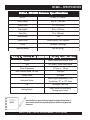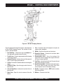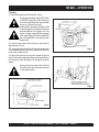
1
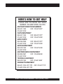
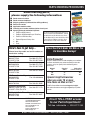
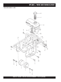
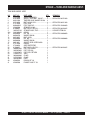
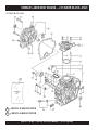
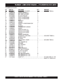
© COPYRIGHT 2004, MULTIQUIP INC.
PARTS AND OPERATION MANUAL
OPERATION AND PARTS MANUAL
Tamping Rammer
Model
MT-86D
(YANMAR L48EE-DRM ENGINE)
Revision #1 (08/19/04)
MULTIQUIP INC..
PARTS DEPARTMENT:
18910 WILMINGTON AVE.
800-427-1244
CARSON, CALIFORNIA 90746 FAX: 800-672-7877
SERVICE DEPARTMENT/TECHNICAL ASSISTANCE:
310-537-3700
800-421-1244
800-478-1244
FAX: 310-537-3927
FAX: 310-631-5032
E-mail:[email protected] • www:multiquip.com
Atlanta • Boise • Dallas • Houston • Newark
Montreal, Canada • Manchester, UK
Rio De Janiero, Brazil • Guadalajara, Mexico
PAGE 2 — MT-86D — PARTS & OPERATION MANUAL — REV. #1 (08/19/04)
HERE'S HOW TO GET HELP
PLEASE HAVE THE MODEL AND SERIAL
NUMBER ON-HAND WHEN CALLING
MULTIQUIP’S MAIN PHONE NUMBERS
800-421-1244
FAX: 310-537-3927
310-537-3700
PARTS DEPARTMENT
800-427-1244
FAX: 800-672-7877
310-537-3700
FAX: 310-637-3284
MAYCO PARTS
800-306-2926
FAX: 800-672-7877
310-537-3700
FAX: 310-637-3284
SERVICE DEPARTMENT
800-478-1244
FAX: 310-537-4259
310-537-3700
MQ POWER SERVICE DEPARTMENT
800-835-2551
FAX: 310-638-8046
310-537-3700
TECHNICAL ASSISTANCE
800-478-1244
FAX: 310-631-5032
WARRANTY DEPARTMENT
800-421-1244, EXT. 279 FAX: 310-537-1173
310-537-3700, EXT. 279
MT-86D — PARTS & OPERATION MANUAL — REV. #1 (08/19/04) — PAGE 3
MT-86D — TABLE OF CONTENTS
MIKASA MT-86D —
Tamping Rammer
YANMAR L48EE-DRM
ENGINE
Here's How To Get Help ............................................3
Table Of Contents .....................................................4
Parts Ordering Procedures .......................................5
Rules For safe Operation ..................................... 6-7
Operation and Safety Decals ....................................8
General Information ..................................................9
Specification ............................................................10
Controls and Components ......................................11
Operation .......................................................... 12-16
Troubleshooting Guide ............................................17
Explanation Of Codes In Remarks Column ............18
Suggested Spare Parts ...........................................19
Name Plate And Decals .................................... 20-21
Crankcase and Engine Assembly ..................... 22-24
Guide Cylinder and Foot Assembly .................. 26-27
Tank and Handle Assembly .............................. 28-29
Cylinder Block Assembly ................................... 30-31
Cylinder Head and Bonnet Assembly ............... 32-33
Crankshaft,Piston and Camshaft Assembly...... 34-35
Lub.,Oil Pump and Governor Assembly ............ 36-37
Cooling and Starting Assembly......................... 38-39
Fuel Injection Pump Assembly .......................... 40-41
Air Cleaner and Muffler Assembly .................... 42-43
Label and Gasket Set Assembly ....................... 44-45
Loose Parts Assembly ...................................... 46-47
NOTE
Terms and Condition Of Sale — Parts ....................48
Specification and part
number are subject to
change without notice.
PAGE 4 — MT-86D — PARTS & OPERATION MANUAL — REV. #1 (08/19/04)
PARTS ORDERING PROCEDURES
When ordering parts,
please supply the following information:
❒
❒
❒
❒
❒
❒
❒
Dealer account number
Dealer name and address
Shipping address (if different than billing address)
Return fax number
Applicable model number
Quantity, part number and description of each part
Specify preferred method of shipment:
Note: Unless otherwise indicated by customer, all
✓ FedEx or UPS Ground
orders are treated as “Standard Orders”, and will
✓ FedEx or UPS Second Day or Third Day
ship within 24 hours. We will make every effort to
✓ FedEx or UPS Next Day
ship “Air Shipments” the same day that the order is
✓ Federal Express Priority One
received, if prior to 2PM west coast time. “Stock
Orders” must be so noted on fax or web forms.
✓ DHL
✓
Truck
Here’s how to get help...
Please have the model and serial number on
hand when calling.
Parts Department
800-427-1244
310-537-3700
Fax: 800-672-7877
Fax: 310-637-3284
Mayco Parts
800-306-2926
310-537-3700
Fax: 800-672-7877
Fax: 310-637-3284
Service Department
800-478-1244
310-537-3700
Fax: 310-537-4259
MQ Power Service Department
800-835-2551
Fax: 310-638-8046
310-537-3700
Technical Assistance
800-478-1244
Fax: 310-631-5032
Warranty Department
800-421-1244, Ext. 279
310-537-3700, Ext. 279
Fax: 310-537-1173
Multiquip’s Main Phone Numbers
800-421-1244
Fax: 310-537-3927
310-537-3700
MULTIQUIP INC.
18910 WILMINGTON AVENUE
POST OFFICE BOX 6254
CARSON, CALIFORNIA 90749
310-537-3700 • 800-421-1244
FAX: 310-537-3927
E-MAIL: [email protected]
WWW: multiquip.com
Place Your Parts Order Via Web or Fax
For Even More Savings!
Extra Discounts!
All parts orders which include complete part numbers
and are received by our automated web parts order
system, or by fax qualify for the following extra
discounts:
Ordered
via
Fax
Standard
orders
3%
Web
5%
Stock orders
($750 list and above)
10%
10%
Special freight allowances
when you order 10 or more
line items via Web or Fax!**
FedEx Ground Service at no charge for freight
No other allowances on freight shipped by any other
carrier.
NOTE: DISCOUNTS ARE SUBJECT TO CHANGE
Direct TOLL-FREE access
to our Parts Department:
Toll-free nationwide — 800-427-1244
MT-86D — PARTS & OPERATION MANUAL — REV. #1 (08/19/04) — PAGE 5
MT-86D — RULES FOR SAFE OPERATION
CAUTION:
Failure to follow instructions in this manual
may lead to serious injury or even death! This
equipment is to be operated by trained and
qualified personnel only! This equipment is
for industrial use only.
The following safety guidelines should always be used when
operating the MT-86D Tamping Rammer:
GENERAL SAFETY
■ DO NOT operate or service this equipment before
reading this entire manual.
■ This equipment should not be operated by persons under 18
years of age.
■ NEVER operate this equipment without proper
protective clothing, shatterproof glasses,
steel-toed boots and other protective devices
required by the job.
■ NEVER operate this equipment when not
feeling well due to fatigue, illness or
taking medicine.
■ NEVER operate this equipment under the
influence or drugs or alcohol.
■ NEVER touch the hot exhaust
manifold, muffler or cylinder. Allow
these parts to cool before servicing
engine or rammer.
■ High Temperatures – Allow the engine to cool before adding
fuel or performing service and maintenance functions. Contact
with hot components can cause serious burns.
■ The engine section of this rammer requires an adequate free
flow of cooling air. Never operate the rammer in any enclosed
or narrow area where free flow of the air is restricted. If the air
flow is restricted it will
cause serious damage to
the rammer or engine and
may cause injury to
people. Remember the
rammer's engine gives off
DEADLY carbon monoxide
gas.
■ Always refuel in a well-ventilated area, away from sparks and
open flames.
■ Always use extreme caution when
working with flammable liquids. When
refueling, stop the engine and allow it
to cool. DO NOT smoke around or near
the machine. Fire or explosion could
result from fuel vapors, or if fuel is spilled
on a hot engine.
■ NEVER use accessories or attachments, which are not
recommended by Multiquip for this equipment. Damage to
the equipment and/or injury to user may result.
■ NEVER operate the rammer in an explosive atmosphere or
near combustible materials. An explosion or fire could result
causing severe bodily harm or even death.
■ Manufacture does not assume responsibility for any accident
due to equipment modifications.
■ Topping-off to filler port is dangerous, as it tends to spill fuel.
■ Whenever necessary, replace nameplate, operation and
safety decals when they become difficult read.
■ Always check the machine for loosened threads or bolts before
starting.
PAGE 6 — MT-86D — PARTS & OPERATION MANUAL — REV. #1 (08/19/04)
MT-86D — RULES FOR SAFE OPERATION
■ NEVER Run engine without air filter. Severe engine may occur.
■ Always service air cleaner frequently to prevent carburetor
malfunction.
■ Always be sure the operator is familiar with proper safety
precautions and operations techniques before using rammer.
■ Always store equipment properly when it is not being used.
Equipment should be stored in a clean, dry location out of the
reach of children.
■ NEVER use accessories or attachments, which are not
recommended by Multiquip for this equipment. Damage to the
equipment and/or injury to user may result.
■ NEVER Run engine without air cleaner. Severe engine damage
may occur.
■ Always read, understand, and follow procedures in Operator’s
Manual before attempting to operate equipment.
■ Always be sure the operator is familiar with proper safety
precautions and operations techniques before using pump.
■ Always store equipment properly when it is not being used.
Equipment should be stored in a clean, dry location out of the
reach of children.
■ Refer to the ROBIN Engine Owner's Manual for engine
technical questions or information recommended by Multiquip
for this equipment. Damage to the equipment and/or injury to
user may result.
Transporting
■ Always shutdown engine before transporting.
■ Tighten fuel tank cap securely and close fuel cock to prevent
fuel from spilling.
■ Drain fuel when transporting rammer over long distances
or bad roads.
■ When placing the rammer inside a truck-bed for transport,
always tie-down the rammer.
Emergencies
■ Always know the location of the nearest fire extinguisher
and first aid kit. Know the location of the nearest telephone.
Also know the phone numbers of the nearest ambulance,
doctor and fire department. This information will be
invaluable in the case of an emergency.
Maintenance Safety
■ NEVER lubricate components or attempt service on a
running machine.
■ Always allow the machine a proper amount of time to cool
before servicing.
■ Keep the machinery in proper running condition.
■ Fix damage to the machine immediately and always replace
broken parts.
■ Dispose of hazardous waste properly. Examples of
potentially hazardous waste are used motor oil, fuel and
fuel filters.
■ DO NOT use food or plastic containers to dispose of
hazardous waste.
MT-86D — PARTS & OPERATION MANUAL — REV. #1 (08/19/04) — PAGE 7
MT-86D — OPERATION AND SAFETY DECALS
PAGE 8 — MT-86D — PARTS & OPERATION MANUAL — REV. #1 (08/19/04)
MT-86D — GENERAL INFORMATION
Definition of Tamping Rammer
The Mikasa MT-86D tamping rammer is a powerful compacting
tool capable of applying a tremendous force in consecutive
impacts to a soil surface. Its applications include soil compacting
for road, embankments and reservoirs as well as backfilling for
gas pipelines, water pipelines and cable installation work.
The impact force of the MT-86D levels and uniformly compacts
voids between soil particles to increase dry density.
Circular motion is converted to create impact force. The MT-86D
tamping rammer develops a powerful compacting force at the
foot of the rammer. To maintain optimum performance, proper
operation and service are essential.
Construction of Tamping Rammer
The Mikasa MT-86D Tamping Rammer is equipped with an Robin
air cooled, four cycle gasoline engine. Transmission of the power
takes place by increasing the engine speed to engage the
centrifugal clutch.
Rammer Gearbox and Spring Cylinder
The Mikasa MT-86D uses an oil bath lubrication system. Always
check the oil level through the oil level sight glass at the rear of
the tamper foot.
Controls
Before starting the MT-86D Tamping Rammer, identify and
understand the function of the controls, see Figure 1 on page 11.
MT-86D — PARTS & OPERATION MANUAL — REV. #1 (08/19/04) — PAGE 9
MT-86D — SPECIFICATIONS
Table1. MT-86D Rammer Specifications
MODEL
MT-86D U.S. (metric)
Overall Height
39.4 in. (1,000 mm)
Overall Width
16.1 in (410 mm)
Over Length
28.3 in (720 mm)
Shoe Size
13 in. (330 mm)
Blows/minute
700
Impact Force
4,500 lbs./blow (2,041 kg/blow)
Clutch
Automatic Centrifugal
Operating Weight
202 lbs. (92 kg)
Table 2. Yanmar L-40 ADRM STD Engine Specifications
NOTE
MODEL
Yanmar L48EE-DRM ENGINE (EPA)
Type
Air-Cooled 4 Stroke Diesel Engine
Piston Displacement
12.14 cu. in. ( 199 cc)
Max. Governed Speed, No Load
3,300 rpm
Cooling System
Air-Cooled
Lubrication System
Diesel Engine Lububricating Oil API
Classification "CC" or "CD" Grade
Fu e l
Automotive Diesel Fuel
Star ting System
Recoil Star ter with Auto-Return
Decompression Device
Specifications are general and are subject to change without notice. If
exact measurements are required, equipment should be weighed and
measured.
PAGE 10 — MT-86D — PARTS & OPERATION MANUAL — REV. #1 (08/19/04)
MT-86D — CONTROLS AND COMPONENTS
Figure A. MT-86D Tamping Rammer
Figure A shows the location of the controls and components
for the MT-86D Tamping Rammer. The functions of each
control is described below:
1. Fuel Tank/Cap – Remove this cap to add diesel fuel.
Use high grade automotive diesel fuel only.
2. Throttle Lever – Controls engine speed and the tamping
action of the rammer.
3. Engine Oil Dipstick – Indicates the level of the engine oil
Use CC class or higer grade motor oil.
4. Oil filter – Prevents dirt and other debris from entering the
engine.
5. Oil Bath Fill Plug – Open this plug to add oil to the oil
bath reservoir.
6. Oil Level Sight Glass – Indicates the level of oil in the oil
bath reservoir.
7. Drain Valve – Open this valve to remove oil from the
bellows.
8.
9.
10.
11.
12.
13.
14.
15.
Foot– Laminated wood with tempered steel plate for
superior shock absorption.
Muffler– Used to reduce noise and emissions.
Engine Air Cleaner – Prevents dirt and other debris
from entering the engine.
Decompression Lever – Use in the starting of the
engine. Press lever to engage. After engine starts lever
will return to original position.
Fuel Filter – Located inside fuel tank. Prevents dirt and
debris from entering fuel system.
Recoil Starting Handle – Used when starting the engine.
Pull starter handle sharply and quickly, then return
starter handle to starter case before releasing.
Handle – To operate rammer GRIP handle assembly
firmly on both sides.
Bellows – Reservoir for oil bath.
MT-86D — PARTS & OPERATION MANUAL — REV. #1 (08/19/04) — PAGE 11
MT-86D — OPERATION
1. Definition of Tamping Rammer
The Mikasa MT-86D diesel rammer is a powerful compacting
tool capable of applying tremendous force in consecutive
impacts to a soil surface. The impact force of the MT-86D levels
and uniformly compacts voids between soil particles to increase
dry density. Its applications include soil compacting for road,
embankment and reservoirs as well as backfilling for gas
pipelines, water pipelines and cable installation work.
3-5. Clean dirt from the recoil starter and foot. Wipe entire unit
clean before operating.
3-6. Replace any missing or damaged Safety/Operation decals.
2. Construction of Tamping Rammer
The rammer is equipped with an air-cooled, four-stroke diesel
engine. Transmission of the power takes place by increasing
engine speed to engage a centrifugal clutch. Circular motion is
converted into vertical motion to create impact force.
3-2. Preparation Inspection:
Rammer Gearbox and Spring Cylinder. This unit uses an oil
bath lubrication system. Check oil level through oil level sight
glass at rear of tamper foot. If oil is not visible, add #10W-30
motor oil. Oil bath contains approx. 1.7 pt. (800cc) for MT-86D.
Fig. 2
3-3. Engine:
Use only automobile diesel fuel (Fig. 1). Check the engine oil
before starting operation and fill the oil regularly (Fig. 2). For
checking the oil level, move the engine to vertical position and
check that the oil is level with the oil inlet (about 700cc).
3-4. Check all nuts, bolts and fasteners for tightness. Retighten
as necessary.
Fig. 1
PAGE 12 — MT-86D — PARTS & OPERATION MANUAL — REV. #1 (08/19/04)
MT-86D — OPERATION
4. Starting
4-1. Move the throttle lever to IDLE position. (Fig. 3)
Throttle lever is used only at three (STOP, IDLE
& OPERATION) positions. When moving the
lever from stop to idle position, depress button
on lever at same time it is moved.
In cold weather, the engine should be started
at operating position or between the idle and
operation position of the throttle lever. Use
caution as higher engine RPM may engage
clutch, when engine starts. Return throttle lever
from starting position to idle position when
engine starts.
4-2. Grip the recoil starter handle and pull it until you feel a
slight resistance. (Fig. 4)
4-3. Press the decompression lever to release decompression.
The decompression lever will return automatically when the
recoil starter is pulled. (Fig. 5)
Fig. 4
4-4. Return the recoil starter, and pull the handle sharply and
quickly. Warm up the engine by running at low speed for three
to five minutes, while checking for fuel leakage or abnormal
sounds.
Do not pull the starter rope all the way to the
end and do not let the starter rope snap back
as damage may result.
Fig. 5
Fig. 3
MT-86D — PARTS & OPERATION MANUAL — REV. #1 (08/19/04) — PAGE 13
MT-86D — OPERATION
5. Operation
5-1. Move the throttle lever quickly from the IDLE to OPERATION
position to start tamping action. DO NOT move the throttle lever
slowly as this may cause damage to the clutch or spring box.
5-2. The tamping rammer is designed to tamp the ground 700
times per minute at an engine speed of 3,300 rpm. Increasing
the engine speed above the recommended rpm will not increase
the rammer effectiveness. Impact will actually decrease because
a resonance is created rather than a tamping effect, and damage
to the unit can result.
5-3. The rammer can be warmed by quickly moving the throttle
lever from the OPERATION to the IDLE position several times
until the rammer operates smoothly.
Fig. 6
5-4. The tamping rammer is designed to travel forward while
tamping. To increase travel speed, pull back slightly on the
handle so that the rear of the foot contacts the soil first.
5-5. To stop tamping, quickly move the throttle lever from the
OPERATION to IDLE position. Do not move the lever slowly as
irregular action and damage may result.
6. Stopping the Engine
6-1. Move throttle lever quickly from idle to STOP while pressing
the throttle lever button. Run the engine for three minutes at idle
speed to allow for proper cool down. Following the above
procedures will prevent improper cylinder lubrication caused
by a overheated engine. (Fig. 6)
Fig. 7
7. Service
CAUTION:
Flammable Liquid: When refueling, stop engine and allow it
to cool.. Do no smoke or allow work to be
performed in the immediate area. Fire or
explosion could result from flames or sparks,
or if fuel is spilled on a hot engine.
Moving Parts: Shut down the engine before
performing service or maintenance functions.
Contact with moving parts can cause serious injury.
High Temperatures: Allow machine and engine to cool before
performing service or maintenance functions. Contact with hot
components can cause serious burns.
PAGE 14 — MT-86D — PARTS & OPERATION MANUAL — REV. #1 (08/19/04)
Fig. 8
MT-86D — OPERATION
7-1. Daily
■ Thoroughly remove dirt and oil from the engine and control
area.
■ Clean or replaces air cleaner as necessary.
■ Check and retighten all fasteners as necessary.
■ Check spring box and bellows for oil leaks. Repair as
needed.
■ Remove element from pre-cleaner at the top of crankcase
(body side) and clean it by air.
7-2. WEEKLY (every 50 hours)
■ Remove the fuel filter cap and inspect for dirt in the fuel
tank. (Fig. 7)
Fig. 9
7-3. Replacement of Lubricant (BODY)
■ Remove the drain plug at the rear of tamper foot and drain
the dirty oil. Refill with clean oil to the middle of the sight
glass. Oil bath contains approx. 1.7 pt. (800 cc) for MT-86D.
INITIAL OIL CHANGE:
After 50 hours of operation
Temperature
20°C (+68°F) or over
10¨C (+14°F) to
0°C (+68°F)
Below 10° (+14°F)
Classification of Oil
SAE 30
CC class or higher
SAE 20
grade
SAE 10W-30
Fig. 10
SECOND OIL CHANGE AND/OR LATER
Every 200 hours of operation
7-4. Replacement of Lubricant (ENGINE)
7-4-1. While the engine is still warm, remove the drain plug. For
quick discharging, it is advisable to take off the oil gauge. Replace
drain plug and refill engine crankcase. (Fig. 8)
7-4-2. Refer to the following chart, for oil types
Inferior quality engine oil and/or lack of oil may cause engine
trouble or shorten engine life.
7-4-3. The interval of oil replacement
INITIAL OIL CHANGE:
After 20 hours of operation
SECOND OIL CHANGE AND/OR LATER:
Every 100 hours of operation
Fig. 11
MT-86D — PARTS & OPERATION MANUAL — REV. #1 (08/19/04) — PAGE 15
MT-86D — OPERATION
7-5. Cleaning the Air Cleaner
Cleaning the Air Cleaner (every 200-300 hours) (Fig. 9)
■ Remove element from pre-cleaner at the top of crankcase
(body side).
■ Wash the element (outside) in detergent solution.
■ Shake out excess moisture and dry the element.
■ Clean inside element with air from the inside of element.
7-6. Cleaning the Oil Filter
Drain oil filter every 100 hours of operation. Replace the oil filter
every 1,000 hours of operation. (Fig. 10)
7-7. Fuel Pipe & Oil Pipe
■
Check fuel line regularly for damage,
paying attention to clamps to assure
a tight fit.
■
Replace fuel line every two years to
maintain original performance.
7-8. Transportation
Maintain upright position of rammer at all times. Transport
rammer in upright position. If machine must be laid down for
transportation, drain the diesel fuel first and lay machine with
muffler side down (Fig. 11)
The fuel filter is installed at the bottom of fuel tank. Should the
rammer be laid on its side, dirt from the fuel filter may contaminate
the injection nozzle, causing damage to the fuel pump.
7-9. Storage
■ When storing the rammer for long periods of time,
thoroughly drain all fuel from line.
■ Clean exterior of rammer with an oil moistened cloth. Cover
and store in a clean, dry place.
PAGE 16 — MT-86D — PARTS & OPERATION MANUAL — REV. #1 (08/19/04)
MT-86D — TROUBLESHOOTING
Engine
A.
B.
Difficult to start
1
No diesel fuel
2
Throttle lever at wrong position (Stop position)
3
Excess engine oil
4
Injection nozzle clogged
5
Recoil starter not pulled with enough speed.
6
Air cleaner clogged
7
Clutch failure
8
Fuel line clogged
Operation not satisfactory
1
Engine speed improperly set.
2
Clutch slips
3
Excess lubricant oil causing irregular jumping or
protective sleeve is heated.
4
Lack of lubricant oil causing irregular jumping.
5
Spring failure
6
Spring cylinder locked
MT-86D — PARTS & OPERATION MANUAL — REV. #1 (08/19/04) — PAGE 17
MT-86D — TEXPLANATION OF CODE IN REMARKS COLUMN
How to read the marks and remarks used in this parts
book.
Items Found In the “Remarks” Column
Serial Numbers-Where indicated, this indicates a serial
number range (inclusive) where a particular part is used.
Model Number-Where indicated, this shows that the
corresponding part is utilized only with this specific model
number or model number variant.
NOTE
The contents of this catalog
are subject to change
without notice.
Items Found In the “Items Number” Column
All parts with same symbol in the number column, , #, +, %, or
>, belong to the same assembly or kit.
*
NOTE
If more than one of the same
reference number is listed,
the last one listed indicates
newest (or latest) part
avaliable.
PAGE 18 — MT-86D — PARTS & OPERATION MANUAL — REV. #1 (08/19/04)
MT-86D —SUGGESTED SPARE PARTS
MT-86D DIESEL RAMMER
1-3 UNITS
1 .... 956200040 ........... THROTTLE LEVER ASSY
1 .... 956108040 ........... THROTTLE WIRE
3 .... 371010060 ........... ELEMENT ASSY
2 .... 954405080 ........... STRAINER, FUEL TANK
3 .... 18325455120 ....... STRAINER ASSY, FUEL
1 .... 0430430015 ......... CAP, FUEL TANK
2 .... 11425035110 ....... STRAINER, OIL LUB.
1 .... 16026076630 ....... ROPE, RECOIL STARTER
NOTE
Part numbers on this Suggested
Spare Parts List may super cede/
replace the P/N shown in the text
pages of this book.
MT-86D — PARTS & OPERATION MANUAL — REV. #1 (08/19/04) — PAGE 19
MT-86D— NAME PLATE AND DECALS
NAME PLATE AND DECALS
PAGE 20 — MT-86D — PARTS & OPERATION MANUAL — REV. #1 (08/19/04)
MT-86D— NAMEPLATE/DECAL LOCATION
NAME PLATE AND DECALS
NO.
1
2
3
4
5
6
7
8
9
*
*
*
*
*
*
*
PART NO.
920101580
920205840
920203330
920205820
920203290
920201950
920205830
DCL86D/76D
PART NAME
QTY.
REMARKS
DECAL: MIKASA MARK
1
DECAL: FUEL DIESEL
1
NPA-584
DECAL: EAR PROTECTION
1
NAA-333
DECAL ENGINE R.P.M 3100-3300 1
DECAL: READ OWNER'S MANUAL 1
NPA-329
PLATE: SERIAL NO. MT-86D
1
ORDER FROM MQ SER. DEPT. W/MODEL & S/N
DECAL: MOTOR OIL
1
DECAL, AIR CLEANER
1
NPA-583
DECAL KIT, MT-86D/MT-76D ............. 1 ............INCLUDES ITEMS W/
*
FOR DECAL ILLUSTRATIONS SEE PAGE 8.
MT-86D — NAME PLATES AND DECALS
MT-86D — PARTS & OPERATION MANUAL — REV. #1 (08/19/04) — PAGE 21
MT-86D — CRANKCASE AND ENGINE ASSY.
CRANKCASE AND ENGINE ASSY.
42B
42C
42E
42A
42D
35-5
35-1
35-2
35-4
35-3
35-5
PAGE 22 — MT-86D — PARTS & OPERATION MANUAL — REV. #1 (08/19/04)
MT-86D — CRANKCASE AND ENGINE ASSY.
CRANKCASE AND ENGINE ASSY.
NO.
PART NO.
PART NAME
1
2
4
5
6
7
8
9
10
11
12
13
14
15
16
17
19
20
22
23
24
25
26
27
28
29
30
31
32
34
35
35-1
35-2
35-3
35-4
35-5
36
372113340
372335090
040006307
040006205
952400690
002219825
372447660
050300500
080100600
001210610
031106100
301300530
040006305
080100520
952400690
002210825
372447670
002210620
372447680
040006205
080200350
371449600
060404010
050101000
371447640
952405610
952405490
002210820
041006007
22512040120
371447630
943020060
943950120
943060070
943060080
943030060
301010210
CRANKCASE
1
CRANK GEAR
1
BEARING 6307
1
BEARING 6205
1
WASHER 9 X 35 X 4.5
1
BOLT 8X25H, SW ....................................... 1 ............. REPLACES 002210825
BEARING COVER
1
O-RING S-50
1
STOP RING R-60
2
BOLT 6X10H
1
WASHER M6
1
CONNECTING ROD
1
BEARING 6305
1
STOP RING R-62
1
WASHER 9304
1
BOLT 8X25H, SW ....................................... 1 ............. REPLACES 002210825
PACKING, FRONT COVER
1
BOLT 6X20H, SW ....................................... 9 ............. REPLACES 002210620
PINION
1
BEARING 6205
1
STOP RING S-35
1
SPACER ..................................................... 1 ............. REPLACES 371335280
OIL SEAL TC-40528
1
O-RING G-100
1
CLUTCH DRUM
1
KEY 5X5X19R
1
LOCK WASHER
1
BOLT 8X20H, SW
1
BEARING 6007Z
1
KEY 4X12
1
CLUTCH ASSY. .......................................... 1 ............. INCLS. ALL ITEMS W/
CLUTCH SHOE (4)
1
CLUTCH BOSS
1
CLUTCH GUIDE (A)
1
CLUTCH GUIDE (B)
1
CLUTCH SPRING ...................................... 2 ............. REPLACES 943030090
LOCK WASHER, CLUTCH
1
*
*
*
*
*
QTY.
REMARKS
*
MT-86D — PARTS & OPERATION MANUAL — REV. #1 (08/19/04) — PAGE 23
MT-86D — CRANKCASE AND ENGINE ASSY.
CRANKCASE AND ENGINE ASSY.
42B
42C
42E
42A
42D
35-5
35-1
35-2
35-4
35-3
35-5
PAGE 24 — MT-86D — PARTS & OPERATION MANUAL — REV. #1 (08/19/04)
MT-86D — CRANKCASE AND ENGINE ASSY.
CRANKCASE AND ENGINE ASSY.
NO.
37
38
41
42
42A#
42B#
42C#
42D#
42E#
43
44
45
46
47
48
49
50
52
53
54
56
57
58
59
60
65
71
72
73
74
75
76
77
78
79
80
81
PART NO.
371448260
022910170
371448220
371213392
371010060
371010030
371010040
371010050
371010070
002210820
371335110
371000010
371000020
371335270
11428412200
001200652
030206150
956200040
956108040
371448000
371448300
26226100402
020310080
030210250
002211050
372213560
914410008
371335100
001211040
020310080
030210250
031110160
371448021
001200630
001200635
030206150
16026078700
PART NAME
QTY.
REMARKS
SPACER 15X24X4
1
NUT M12
1
PACKING, AIR CLEANER
1
AIR CLEANER ASSY ........................... 1 ............INCLUDES ITEMS W/# REPLACES 371213390
ELEMENT ASSY
1
BODY ASSY
1
BACK PLATE
1
SEAT, AIR CLEANER
1
BOLT ASSY.
1
BOLT 8X20H, SW
4
INTAKE PIPE
1
HOSE BAND (B)
1
HOSE BAND (B)
1
INTAKE FLANGE
1
GASKET, AIR INTAKE
1
BOLT 6X60
2
WASHER SW M6
2
THROTTLE LEVER ASSY
1
THROTTLE WIRE
1
LEVER STAY
1
CLIP (M)
1
STUD M10X20 PLATED
2
NUT M10
2
WASHER SW M10
2
BOLT 10X50H, SW
2
FRONT COVER MQ
1
ENGINE ASSY L48EE-DRM
1
UNDER PROTECTOR
1
BOLT 10X40 H
2
NUT M10
2
WASHER SW M10
2
WASHER PW M10
1
LINK PROTECTOR
1
BOLT 6X30
1
BOLT 6X35
1
WASHER SW M6
2
CLAMP WIRE
2
MT-86D — PARTS & OPERATION MANUAL — REV. #1 (08/19/04) — PAGE 25
MT-86D — CYLINDER GUIDE AND FOOT ASSY.
CYLINDER GUIDE AND FOOT ASSY.
EXCLUDE 61, 62 AND 63
PAGE 26 — MT-86D — PARTS & OPERATION MANUAL — REV. #1 (08/19/04)
MT-86D — CYLINDER GUIDE AND FOOT ASSY.
CYLINDER GUIDE AND FOOT ASSY.
NO.
PART NO.
61
652423290
62
080100150
63
352210680
64
372427700
65
020118150
66
352431430
67
352437470
68
372335260
69
372213180
70
372213570
71
352110042
73
050100950
74
050101100
75
014210020
76
014210035
77
953405270
78
953405260
80
354446170
82
354212490
86
354010010
87
050931500
88-1
354910020
89
012710035
90
959010150
91
953404670
92
050201500
100
352910081
101# 352326620
102# 352326630
103
015112075
104# 001611259
105# 015110055
106
021112140
107
030212300
108# 021110120
109# 030210250
113-1# 354332070
114
352441730
115
354336352
115
354336352
116
354442340
117
011008040
118
020108060
*
*
*
*
PART NAME
QTY.
REMARKS
PISTON PIN ......................................... 1 ............REPLACES 352423290
STOP RING R-15
2
PISTON ROD
1
PISTON END
1
NUT M18, P1.5
1
STOPPER,UPPER
1
STOPPER,LOWER
1
MAIN SPRING
2
SPRING CYLINDER
1
FOOT PLATE
1
PROTECTION SLEEVE ...................... 1 ........... REPLACES 352110040
O-RING G-95
1
O-RING G-110
1
SOCKET HEAD BOLT 10X20 T .......... 4 ............REPLACES 001521020
SOCKET HEAD BOLT 10X35 T .......... 4 ............REPLACES 001521035
PLUG 1/4X14 13L
2
PACKING 1/4(CU)
2
PIN 6D-8.5L
2
GUIDE CYLINDER(L)
1
BELLOWS,ORANGE
1
REPLACES 354332780
O-RING JAS03150
2
BELLOWS CLAMP CP ........................ 2 ............INCLS. ALL ITEMS W/
BOLT 10X35 H,SW .............................. 4 ............REPLACES 002211035
LEVEL GAUGE,PLUG TYPE
1
COPPER PACKING 17X25.5X1
1
O-RING P-150
1
FOOT ASSY 330W-W/F.COVER ........ 1 ............INCLS. ALL ITEMS W/#
FOOT 330B-331L
1
METAL SHEET 330B
1
SUNK HEAD BOLT 12X80 H ............... 4 ............REPLACES 001611256
SUNK HEAD BOLT 12X100 H ............. 2 ............REPLACES 001611260
SUNK HEAD BOLT 10X55 H ............... 7 ............REPLACES 001611051
NYLON NUT M12 ................................ 4 ............REPLACES 022711214
WASHER SW M12
4
NYLON NUT M10 ................................ 7 ............REPLACES 022711012
WASHER SW M10
7
FOOT COVER
1
SPRING SEAT 80D-1.6T
1
BELLOWS CLAMP MT68, 7OV ........... 2 ............REPLACES 354329380
BELLOWS CLAMP (1.6T) 171D
2
BAND GUIDE,BELLOWS
2
BOLT 8X40H ........................................ 2 ............REPLACES 001210840
NUT M8 ................................................ 2 ............REPLACES 020308060
*
MT-86D — PARTS & OPERATION MANUAL — REV. #1 (08/19/04) — PAGE 27
MT-86D — TANK AND HANDLE ASSY.
TANK AND HANDLE ASSY.
9A
PAGE 28 — MT-86D — PARTS & OPERATION MANUAL — REV. #1 (08/19/04)
MT-86D — TANK AND HANDLE ASSY.
TANK AND HANDLE ASSY.
NO.
1
2
3
4
5
6
7
8
9
9A
10
11
12
13
14
15
21
22
23
26
27
28
29
30
31
32
40
41
*
PART NO.
351319900
014210020
033121009
012210020
371113650
0430430015
954405080
011808015
18325455120
24341000450
020106050
030206150
001210815
020108060
030208200
009110011
371113560
371448010
011808015
18366659330
18325059050
11435459070
11428459710
10699044660
12472259050
18325059040
953405810
953405800
PART NAME
QTY.
REMARKS
SHOCK ABSORBER
2
SOCKET HEAD BOLT 10X20T ........... 4 ............REPLACES 001521020
TOOTHED LOCK WASHER B M10 4
BOLT 10X20H, SW .............................. 4 ............REPLACES 002211020
FUEL TANK
1
FUEL TANK CAP .................................. 1 ............REPLACES 953404650
STRAINER (#100)
1
BOLT 8X15H, SW, PW ......................... 3 ............REPLACES 002410815
STRAINER ASSY, FUEL ...................... 1 ............INCLUDES ITEM W/
O-RING
1
NUT M6 ............................................... 3 ............REPLACES 020306050
WASHER SW M6
3
BOLT 8X15H
1
NUT M8 ................................................ 1 ............REPLACES 020308060
WASHER SW M8
2
SOCKET HEAD SCREW 8X20
1
HANDLE
1
SIDE PROTECTOR
1
BOLT 8X15H, SW, PW ......................... 3 ............REPLACES 002410815
PIPE, FUEL DRAIN
1
PIPE, FUEL OIL
1
PIPE, FUEL RETURN
1
JOINT
1
CLAMP
5
CLAMP
2
PIECE
1
PACKING PF 1/8
1
FLANGE PLUG PF 1/8
1
*
MT-86D — PARTS & OPERATION MANUAL — REV. #1 (08/19/04) — PAGE 29
YANMAR L48EE-DRM ENGINE — CYLINDER BLOCK ASSY.
CYLINDER BLOCK ASSY.
2 = SEE PG. 32 AND 33 FOR P/N
7 = SEE PG. 40 AND 41 FOR P/N
PAGE 30 — MT-86D — PARTS & OPERATION MANUAL — REV. #1 (08/19/04)
YANMAR L48EE-DRM ENGINE — CYLINDER BLOCK ASSY.
CYLINDER BLOCK ASSY.
NO
PART NO
1
71477101560
6
11435001700
7*
26106100122
8*
26106080352
9
22312040080
10
11425001200
11
11425001210
12
11425001221
13
11425001251
14
12495001250
15+
11477101330
21+
11465001380
22
11425001800
28
11425001830
11425001841
29+
30
11427001600
31
26226060182
32
26226060222
33
26366060002
34+
11425001412
35
11428401452
38%
11425002100
41
10542501690
42
11429901760
44#+ 11429901950
45+
22190160002
46
11429902030
47
11425002113
48
16011002220
49
16021002220
50
24162152112
51
26106080122
52
23876010000
53
11425035150
54
26106060252
55%
11425002200
56%
11425002210
57
71477192620
PART NAME
QTY.
REMARKS
BLOCK ASSY. CYLINDER ........................... 1 ....................INCLUDES ITEM W/
*
COVER, STARTER
1
BOLT M10X 12 PLATED
2
BOLT M 8X 35 PLATED
1
PIN 4X8, STRAIGHT
2
STUD, CYLINDER HEAD
2
STUD, CYLINDER HEAD
2
NUT 8
2
CAP NUT 8
2
WASHER
4
GASKET, CYLINDER HEAD CMP
1
O-RING
1
SHIM SET
1
COVER, INSPEC. WINDOW
1
GASKET
1
PARALLEL PIN 8 X 12
2
STUD M 6 X 18 PLATED
1
STUD M 6 X 22 PLATED
2
NUT M 6
3
GASKET CRANKCASE
1
COVER ASSY. CASE DRM .......................... 1 ....................INCLUDES ITEMS W/%
BEARING, MAIN
1
PLUG M16
2
CAP, W/LUB.OIL GAUGE ............................. 1 ....................INCLUDES ITEM W/#
O-RING
1
SEAL WASHER 16S
2
RETAINER
1
BALL BEARING
1
SEAL, OIL
1
SEAL, OIL
1
NEEDLE BEARING
1
BOLT M 8 X 12 PLATED
1
PLUG PTI/8, SCREW
1
PIPE, L.O. INLET
1
BOLT M 6 X 25 PLATED
14
MAIN BEARING US = 0.25
1
MAIN BEARING US = 0.50
1
GASKET KIT ....................................................... 1 ...................... INCLUDES ITEMS W/+. SEE
...................................................................................................... GASKET KIT PAGES 44-45
MT-86D — PARTS & OPERATION MANUAL — REV. #1 (08/19/04) — PAGE 31
YANMAR L48EE-DRM ENGINE — CYLINDER HEAD AND COVER ASSY.
CYLINDER HEAD AND COVER ASSY.
MT-86D — L40ADRM YANMAR ENGINE — CYLINDER HEAD AND BONNET
1 = SEE PG. 30 AND 31 FOR P/N
PAGE 32 — MT-86D — PARTS & OPERATION MANUAL — REV. #1 (08/19/04)
YANMAR L48EE-DRM ENGINE — CYLINDER HEAD AND COVER ASSY.
CYLINDER HEAD AND BONNET ASSY.
NO
PART
NO — L40ADRM
PART NAME
QTY.
REMARKS
MT-86D
YANMAR
ENGINE
—
CYLINDER
HEAD AND BONNET
1
11477111020
CYLINDER HEAD
1
6
11477111100
VALVE, SUCTION
1
7
11477111110
VALVE, EXHAUST
1
8
11425011120
SPRING, VALVE
2
9
11425011180
RETAINER, SPRING
2
10
71425011570
COTTER ASSY.
2
12
11477111250
SUPPORT CMP, ARM .............................. 1 ................. INCLUDES ITEM W/
*
13
11477111260
SUPPORT, ROCKER ARM
1
*
14
11477111650
ARM ASSY. INTAKE
1
16*
11425011240
SCREW, VALVE ADJUST
1
17
26856060002
LOCK NUT 6
1
18
11477111660
ARM ASSY., EXHAUST
1
20*
11425011240
SCREW, VALVE ADJUST
1
21
26856060002
LOCK NUT 6
1
22
22242000120
CIRCLIP 12
2
23*
+
11425011340
SEAL, VALVE STEM
2
24+
11477111461
GASKET, NOZZLE
1
25
11477111470
SPACER, NOZZLE
1
26
11425011600
WASHER
2
27
11926011370
CAP, VALVE
2
28
11425011901
RETAINER
1
29
22351040008
SPRING PIN 4 X 8
1
30
26106060452
BOLT M 6 X 45 PLATED
2
31
26226060652
STUD M 6 X 65 PLATED
2
32
26366060002
NUT M 6
2
33+
11477111310
GASKET, BONNET
1
34
11477111970
BONNET ASSY. HEAD ............................. 1 ................. INCLUDES ITEM W/#
36#
11428803580
SHAFT ASSY., DECOMP.
1
39#
11428803641
SPRING
1
40#
11428803950
PIN
1
46
26106060552
BOLT M 6 X 55 PLATED
3
57
71477192620
GASKET KIT .................................................... 1 ................... INCLUDES ITEMS W/+. SEE
................................................................................................ GASKET KIT PAGES 44-45
MT-86D — PARTS & OPERATION MANUAL — REV. #1 (08/19/04) — PAGE 33
YANMAR L48EE-DRM ENG. — CRANKSHAFT, PIS. & CAMSHAFT ASSY.
CRANKSHAFT, PISTON AND CAMSHAFT ASSY.
1 = SEE PG. 30 AND 31 FOR P/N
PAGE 34 — MT-86D — PARTS & OPERATION MANUAL — REV. #1 (08/19/04)
YANMAR L48EE-DRM ENG. — CRANKSHAFT, PIS. & CAMSHAFT ASSY.
CRANKSHAFT, PISTON AND CAMSHAFT ASSY.
NO
PART NO
PART NAME
QTY.
REMARKS
1
71477114580
CAMSHAFT ASSY., D
1
6
11425014200
TAPPET
2
7
11477114260
TAPPET, F.O.
1
8
11425014450
ROD, PUSH
2
12
71478121700
CRANKSHAFT ASSY.
1
18
10385401221
NUT, M16
1
19
11428821402
FLYWHEEL, DRM
1
21
11425021550
WASHER, FLYWHEEL
1
22
22512040120
KEY, 4 X 12
1
23
18325021350
SPACER
1
24
71477222720
PISTON, W/RINGS ................................... 1 ................. INCLUDES ITEM W/#
26#
71477022500
RING SET, PISTON
1
32
11429922300
PIN, PISTON
1
33
22252000190
CIRCLIP 19
2
34
71477023700
ROD ASSY., CONNECTING ..................... 1 ................. INCLUDES ITEM W/
*
37
11926523200
BOLT, ROD
1
*
38
11477023100
BUSH, PISTON PIN
2
39*
71477023600
BEARING, CRANKPIN
1
41*
71477022610
BEARING, PIN U.S=0.25
1
43*
71477023620
BEARING, PIN U.S=0.50
1
45*
22512040120
KEY 4 X 12
1
MT-86D — PARTS & OPERATION MANUAL — REV. #1 (08/19/04) — PAGE 35
YANMAR L48EE-DRM ENGINE —LUB. OIL PUMP AND GOVERNOR ASSY.
LUB. OIL PUMP AND GOVERNOR ASSY.
1 = SEE PG. 30 AND 31 FOR P/N
PAGE 36 — MT-86D — PARTS & OPERATION MANUAL — REV. #1 (08/19/04)
YANMAR L48EE-DRM ENGINE —LUB. OIL PUMP AND GOVERNOR ASSY.
LUB. OIL PUMP AND GOVERNOR ASSY.
NO
PART NO
PART NAME
QTY.
REMARKS
1
11465032010
PUMP ASSY. LUB. OIL
1
6
11425032070
COVER, LUB. OIL PUMP
1
7+
10333832570
O-RING
1
8
22312030160
PARALLEL PIN 3 X 16
1
9
26476060142
BOLT, M 6 X 14, TAPPING
3
10
11425035110
STRAINER, LUB. OIL ............................. 1.................... INCLUDES ITEM W/#
12#+ 24341000224
O-RING 1A S-22.4
1
13
26106060162
BOLT M 6 X 16 PLATED
1
14
71425061500
LEVER ASSY. GOVERNOR .................... 1.................... INCLUDES ITEM W/
*
19
22322030200
TAPER PIN 3 X 20
1
*
20
22322030200
TAPER PIN 3 X 20
1
21*
71477061100
GOVERNOR ASSY.
1
27
11477061190
WASHER
1
28
11477166050
HANDLE, REGULATOR
1
30
10210067080
BOLT, ADJUSTING
1
31
26117040088
BOLT M 4 X 8 PLATED
1
32
11477066010
SPRING, REGULATOR
1
33
11425066200
SPRING, RETURN
1
34
11477166550
TORQUE SPRING ASSY.
1
39
11477266100
BASE, HANDLE
1
40
266961000002
NUT M10
1
41
13521061090
LEAD
2
42
22451060000
WIRE 0.6
2
43
11425066440
BOLT, ADJUSTING
1
44
26757060002
NUT 6
1
45
26106060202
BOLT M 6 X 20 PLATED
1
46
26476060142
BOLT M 6 X 14 TAPPING
1
47
11477061520
BEARING, NEEDLE
2
48
11477061600
SEAL, OIL
1
49
11477061610
WASHER, THRUST
1
50
11425266252
SPRING, RETURN
1
57
71477192620
GASKET KIT ................................................. 1 ...................... INCLUDES ITEMS W/+. SEE
................................................................................................ GASKET KIT PAGES 44-45
MT-86D — PARTS & OPERATION MANUAL — REV. #1 (08/19/04) — PAGE 37
YANMAR L48EE-DRM ENGINE —COOLING AND STARTING ASSY.
COOLING AND STARTING ASSY.
1 = SEE PG. 30 AND 31 FOR P/N
2 = SEE PG. 32 AND 33 FOR P/N
PAGE 38 — MT-86D — PARTS & OPERATION MANUAL — REV. #1 (08/19/04)
YANMAR L48EE-DRM ENGINE —COOLING AND STARTING ASSY.
COOLING AND STARTING DEVICE ASSY.
NO
PART NO
PART NAME
QTY.
REMARKS
1
11429945210
COVER, CYLINDER
1
2
26106060122
BOLT M 6 X 12 PLATED
1
3
11477145110
CASE, COOLING FAN
1
4
11425045310
COLLAR
4
5
11425045330
SEAL, FAN CASE
1
6
11437045351
BOLT, FAN CASE
4
7
11426076051
RECOIL STARTER D ASSY. .................. 1.................... INCLUDES ITEM W/#
8
11426076251
RECOIL STARTER D ASSY. ................... 1.................... INCLUDES ITEM W/
*
9 #
11426076520
CASE D, W/NO LABEL
1
*
10 # 16026076520
REEL, RECOIL
1
11*# 16026076530
RATCHET
1
12*# 16026076540
SPRING, SPRIAL
1
13*# 16026076550
WASHER, THRUST
1
14*# 16026076560
SPRING, FRICTION
1
15*# 16029076570
SPRING, RETURN
1
16*# 16026076580
COVER, SPRING
1
17*# 16026076590
PLATE, FRICTION
1
18*# 16026076600
CIRCLIP, E
1
20*# 11425076620
KNOB, STARTER
1
21*# 16026076630
ROPE, STARTER
1
22#*
11425076590
PULLEY, STARTER
1
23
26106060082
BOLT M 6 X 8 PLATED
4
24
26106060122
BOLT M 6 X 12 PLATED
3
25
12910061850
PLUG, 12 BORE
1
26
11425045301
RUBBER, CUSHION
4
MT-86D — PARTS & OPERATION MANUAL — REV. #1 (08/19/04) — PAGE 39
YANMAR L48EE-DRM ENGINE —FUEL INJECTION PUMP ASSY.
FUEL INJECTION PUMP ASSY.
1 = SEE PG. 30 AND 31 FOR P/N
2 = SEE PG. 32 AND 33 FOR P/N
PAGE 40 — MT-86D — PARTS & OPERATION MANUAL — REV. #1 (08/19/04)
YANMAR L48EE-DRM ENGINE —FUEL INJECTION PUMP ASSY.
FUEL INJECTION PUMP ASSY.
NO
PART NO
PART NAME
QTY.
REMARKS
1
71435051200
PUMP ASSY., F. INJECT. ....................... 1.................... INCLUDES ITEM W/
*
2
10554651020
GASKET
1
*
3
11425051080
PLATE
1
4*
11425051160
SPRING
1
5*
11435051200
BODY, F.I. PUMP
1
11*
11425051300
VALVE ASSY., DELIVERY
1
14*
10554651330
SPRING, DELIVERY VALVE
1
15*
11425051340
HOLDER, F. I. P. DELIVERY
1
16*
12455051350
GASKET, DELIVERY
2
17*
11425051600
LEVER ASSY., CONTROL
1
18*
11425051640
SEAT A, SPRING
1
19*
11425051650
SEAT B, SPRING
1
20*
22351020006
SPRING PIN 2 X 6
2
21*
22351030008
SPRING PIN 3 X 8
2
22*
71477153100
VALVE ASSY., F. INJECT
1
23
11477153000
NOZZLE ASSY.
1
24
11959353080
NUT, NOZZLE CASE
1
25
11425053120
SPRING, NOZZLE
1
26
11959353130
RETAINER, SPRING
1
27
11477553140
SPACER, VALVE STOP
1
28
11477553210
PIN
2
29
11477553100
HOLDER ASSY.
1
32
11477553330
PIN
1
33
11425053400
SHIM PACK
1
45
11477159802
PIPE, FUEI INJECTION
1
MT-86D — PARTS & OPERATION MANUAL — REV. #1 (08/19/04) — PAGE 41
YANMAR L48EE-DRM ENGINE — AIR CLEANER AND MUFFLER ASSY.
AIR CLEANER AND MUFFLER ASSY.
2 = SEE PG. 28 AND 29 FOR P/N
PAGE 42 — MT-86D — PARTS & OPERATION MANUAL — REV. #1 (08/19/04)
YANMAR L48EE-DRM ENGINE — AIR CLEANER AND MUFFLER ASSY.
MUFFLER ASSY.
NO
PART NO
1
11477212010
2
11477112200
3
26106060252
4
26226060142
5
26226060552
6
11428413500
9
26106060182
10
11425013201
11
26106060142
12
26216080182
13
26366080002
14
11428412200
PART NAME
QTY.
REMARKS
PIPE, AIR INTAKE
1
GASKET, AIR INTAKE
1
BOLT M 6 X 25 PLATED
2
STUD M 6 X 14 PLATED
1
STUD M 6 X 55 PLATED
2
MUFFLER ASSY.
1
BOLT, M 6 X 18 PLATED
1
GASKET, NON-ASB.
1
STUD M 6 X 14 PLATED
1
STUD, M 8 X 18 PLATED
2
NUT, M 8
2
GASKET, AIR INTAKE .............................. 1 ................. SEE GASKET SET PAGES 44-45
MT-86D — PARTS & OPERATION MANUAL — REV. #1 (08/19/04) — PAGE 43
YANMAR L48EE-DRM ENGINE — LABEL AND GASKET SET ASSY.
LABEL AND GASKET SET ASSY.
PAGE 44 — MT-86D — PARTS & OPERATION MANUAL — REV. #1 (08/19/04)
YANMAR L48EE-DRM ENGINE — LABEL AND GASKET SET ASSY.
TOOL, LABEL AND GASKET SET ASSY.
NO
PART NO
PART NAME
QTY.
REMARKS
3
11425007111
LABEL, YANMAR
1
5
71477192620
GASKET SET ......................................... 1.................... INCLUDES ITEM W/
*
6
11477101330
GASKET, CYLINDER HEAD CMP.
1
7
11425001380
O-RING
1
8*
11425001412
GASKET, CRANKCASE
1
9*
11425001841
GASKET
1
10*
11425011340
SEAL, VALVE STEM
2
11*
11477111461
GASKET, NOZZLE
1
12*
11477112200
GASKET, AIR INTAKE
1
13*
11428412200
GASKET, AIR INTAKE
1
14*
11425013201
GASKET, NON-ASB
1
15*
11477111310
GASKET, BONNET
1
16*
11429901950
O-RING
1
17*
22190160002
SEAL WASHER 16S
2
18*
24341000224
O-RING 1A S-22.4
1
19*
10333832570
O-RING
1
20*
11426107350
LABEL
1
23
11425092101
F.W. LOCKING HANDLE
1
24
11425092130
REMOVER, FLYWHEEL
1
26
26116060454
BOLT M 6 X 45 PLATED
4
27
26116080454
BOLT M 8 X 45 PLATED
3
28
26716060002
NUT M 6
8
29
26716080002
NUT M 8
6
30
11425092301
GUIDE, OIL SEAL
1
31
11425092311
INSTALLING TOOL
1
32
11425092350
INSTALLING TOOL
1
MT-86D — PARTS & OPERATION MANUAL — REV. #1 (08/19/04) — PAGE 45
YANMAR L48EE-DRM ENGINE — LOOSE PARTS ASSY.
LOOSE PARTS ASSY.
PAGE 46 — MT-86D — PARTS & OPERATION MANUAL — REV. #1 (08/19/04)
YANMAR L48EE-DRM ENGINE — LOOSE PARTS ASSY.
LOOSE PARTS ASSY.
NO
PART NO
1
18325455120
2
24341000450
3*
1142845910
4#
12476659050
5#
10699044660
6#
18325059040
7#
18325059050
8#
12472259050
9#
11465459070
10#
18326659050
11#
11428459710
12
16071078710
13
26226100452
PART NAME
QTY.
REMARKS
STRAINER ASSY., FUEL ....................... 1.................... INCLUDES ITEM W/
*
O-RING 1A S-45.0
1
PIPE ASSY., FUEL OIL .......................... 1.................... INCLUDES ITEM W/#
CLAMP 12
2
CLIP, HOSE
2
PIECE
1
PIPE, FUEL OIL
1
CLAMP 9
2
PIPE, FUEL RETURN
1
HOSE, RUBBER
1
JOINT
1
CLAMP, WIRE
2
STUD M10X 45 PLATED
2
MT-86D — PARTS & OPERATION MANUAL — REV. #1 (08/19/04) — PAGE 47
Effective: October 1, 2002
PAYMENT TERMS
TERMS AND CONDITIONS OF SALE — PARTS
5.
Parts must be in new and resalable condition, in the original Multiquip package (if
any), and with Multiquip part numbers
clearly marked.
6.
The following items are not returnable:
Terms of payment for parts are net 10 days.
FREIGHT POLICY
All parts orders will be shipped collect or
prepaid with the charges added to the invoice.
All shipments are F.O.B. point of origin.
Multiquip’s responsibility ceases when a
signed manifest has been obtained from the
carrier, and any claim for shortage or damage
must be settled between the consignee and the
carrier.
a. Obsolete parts. (If an item is in the
price book and shows as being
replaced by another item, it is
obsolete.)
b. Any parts with a limited shelf life
(such as gaskets, seals, “O” rings,
and other rubber parts) that were
purchased more than six months prior
to the return date.
MINIMUM ORDER
The minimum charge for orders from Multiquip is $15.00 net. Customers will be asked
for instructions regarding handling of orders
not meeting this requirement.
c. Any line item with an extended dealer
net price of less than $5.00.
RETURNED GOODS POLICY
d. Special order items.
Return shipments will be accepted and credit
will be allowed, subject to the following provisions:
e. Electrical components.
1.
h. Items purchased in kits.
2.
A Returned Material Authorization must
be approved by Multiquip prior to shipment.
To obtain a Return Material Authorization, a list must be provided to Multiquip
Parts Sales that defines item numbers,
quantities, and descriptions of the items
to be returned.
a. The parts numbers and descriptions
must match the current parts price
list.
b. The list must be typed or computer
generated.
c. The list must state the reason(s) for
the return.
d. The list must reference the sales
order(s) or invoice(s) under which
the items were originally purchased.
e. The list must include the name and
phone number of the person requesting the RMA.
3.
A copy of the Return Material Authorization must accompany the return shipment.
4.
Freight is at the sender’s expense. All
parts must be returned freight prepaid to
Multiquip’s designated receiving point.
f. Paint, chemicals, and lubricants.
g. Decals and paper products.
7.
The sender will be notified of any
material received that is not acceptable.
8.
Such material will be held for five
working days from notification, pending
instructions. If a reply is not received
within five days, the material will be returned to the sender at his expense.
9.
Credit on returned parts will be issued at
dealer net price at time of the original
purchase, less a 15% restocking charge.
Multiquip reserves the right to quote and sell
direct to Government agencies, and to Original Equipment Manufacturer accounts who
use our products as integral parts of their own
products.
SPECIAL EXPEDITING SERVICE
A $35.00 surcharge will be added to the invoice
for special handling including bus shipments,
insured parcel post or in cases where Multiquip
must personally deliver the parts to the carrier.
LIMITATIONS OF SELLER’S LIABILITY
Multiquip shall not be liable here under for
damages in excess of the purchase price of the
item with respect to which damages are
claimed, and in no event shall Multiquip be
liable for loss of profit or good will or for any
other special, consequential or incidental damages.
LIMITATION OFWARRANTIES
No warranties, express or implied, are made
in connection with the sale of parts or trade
accessories nor as to any engine not manufactured by Multiquip. Such warranties made in
connection with the sale of new, complete units
are made exclusively by a statement of warranty packaged with such units, and Multiquip
neither assumes nor authorizes any person to
assume for it any other obligation or liability
whatever in connection with the sale of its
products. Apart from such written statement of
warranty, there are no warranties, express,
implied or statutory, which extend beyond the
description of the products on the face hereof.
10. In cases where an item is accepted, for
which the original purchase document
can not be determined, the price will be
based on the list price that was effective
twelve months prior to the RMA date.
11. Credit issued will be applied to future
purchases only.
PRICING AND REBATES
Prices are subject to change without prior
notice. Price changes are effective on a specific date and all orders received on or after that
date will be billed at the revised price. Rebates
for price declines and added charges for price
increases will not be made for stock on hand
at the time of any price change.
PAGE 48 — MT-86D — PARTS & OPERATION MANUAL — REV. #1 (08/19/04)
NOTE PAGE
MT-86D — PARTS & OPERATION MANUAL — REV. #1 (08/19/04) — PAGE 49
=== OPERATION
AND PARTS MANUAL
HERE'S HOW TO GET HELP
PLEASE HAVE THE MODEL AND SERIAL
NUMBER ON-HAND WHEN CALLING
MULTIQUIP’S MAIN PHONE NUMBERS
800-421-1244
FAX: 310-537-3927
310-537-3700
PARTS DEPARTMENT
800-427-1244
FAX: 800-672-7877
310-537-3700
FAX: 310-637-3284
MAYCO PARTS
800-306-2926
FAX: 800-672-7877
310-537-3700
FAX: 310-637-3284
SERVICE DEPARTMENT
800-478-1244
FAX: 310-537-4259
310-537-3700
MQ POWER SERVICE DEPARTMENT
800-835-2551
FAX: 310-638-8046
310-537-3700
TECHNICAL ASSISTANCE
800-478-1244
FAX: 310-631-5032
WARRANTY DEPARTMENT
800-421-1244, EXT. 279 FAX: 310-537-1173
310-537-3700, EXT. 279
MULTIQUIP INC.
POST OFFICE BOX 6254
CARSON, CA 90749
310-537-3700 • 800-421-1244
FAX: 310-537-3927
E-MAIL: [email protected]
WWW: multiquip.com
Atlanta • Boise • Dallas • Houston • Newark
Quebec, Canada • Manchester, UK • Rio De Janiero, BR • Guadalajara, MX
manufactured for Multiquip Inc.
by
MIKASA SANGYO CO., LTD. Tokyo, Japan