1
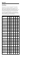
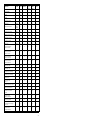
METROLOGIC INSTRUMENTS, INC.
MS6720 Hand-Held Laser Scanner
Installation and User’s Guide
MLPN 2368
Printed in USA
October 1998
Locations:
USA Corporate Headquarters
Metrologic Instruments, Inc.
90 Coles Road
Blackwood, NJ 08012
Customer Service: 1-800-ID-METRO
Tel: 609-228-8100
Fax: 609-228-6673
[email protected]
www.metrologic.com
Europe
Metrologic Instruments GmbH
Dornierstrasse 2
82178 Puchheim b.
Munich, Germany
Tel: 49-89-89018-0
Fax: 49-89-89019-200
[email protected]
ASIA
Metrologic Asia (PTE) Ltd.
31, Kaki Bukit Road 3
#05-08 Techlink
Singapore 417818
Tel: 65-842-7155
Fax: 65-842-7166
[email protected]
South America
Metrologic Instruments
Rua Flórida, 1.821-5°Andar-Brooklin
CEP 04571-090, São Paulo-SP, Brasil
Outside Brazil:
Tel: 55-11-5505-6568
Fax: 55-11-5505-1681
[email protected]
In Brazil:
Tel: 55-11-5505-2396
Fax: 55-11-5507-2301
[email protected]
Copyright
© 1998 by Metrologic® Instruments, Inc. All rights reserved. No part of this work may
be reproduced, transmitted, or stored in any form or by any means without prior written
consent, except by reviewer, who may quote brief passages in a review, or provided for
in the Copyright Act of 1976.
Products and brand names mentioned in this document are trademarks of their
respective companies.
Scope of this Manual
This manual contains all information about the basic operation and usage for the
MS6720.
Material in this document is presented in a user-friendly manner and should be easily
understood. However, it is helpful if the reader is familiar with the general
use and operation of a scanner.
ii
Table of Contents
Introduction . . . . . . . . . . . . . . . . . . . . . . . . . . . . . . . . . . . . . . . . . . . . . . . . . . . 1
Scanner and Accessories . . . . . . . . . . . . . . . . . . . . . . . . . . . . . . . . . . . . . . . . . 2
Quick Start . . . . . . . . . . . . . . . . . . . . . . . . . . . . . . . . . . . . . . . . . . . . . . . . . . . . 3
Operational Test . . . . . . . . . . . . . . . . . . . . . . . . . . . . . . . . . . . . . . . . . . . . . . . 4
Scanner Installation: Powered by External Power Supply . . . . . . . . . . . . . . . 5
Scanner Installation: Powered by the Host Device . . . . . . . . . . . . . . . . . . . . . 6
Scanner Installation: to the PC for the Scanner with Built-In
PC Keyboard Wedge Interface . . . . . . . . . . . . . . . . . . . . . . . . . . . . . . . . . . . . 7
The MS6720 Stand . . . . . . . . . . . . . . . . . . . . . . . . . . . . . . . . . . . . . . . . . . . . . 8
Scanner Parts . . . . . . . . . . . . . . . . . . . . . . . . . . . . . . . . . . . . . . . . . . . . . . . . . . 9
Audible Indicators . . . . . . . . . . . . . . . . . . . . . . . . . . . . . . . . . . . . . . . . . . . . 10
Failure Modes . . . . . . . . . . . . . . . . . . . . . . . . . . . . . . . . . . . . . . . . . 11
Visual Indicators . . . . . . . . . . . . . . . . . . . . . . . . . . . . . . . . . . . . . . . . . . . . . . 12
Label . . . . . . . . . . . . . . . . . . . . . . . . . . . . . . . . . . . . . . . . . . . . . . . . . . . . . . . 13
Depth of Field Specifications . . . . . . . . . . . . . . . . . . . . . . . . . . . . . . . . . . . . 14
Normal Depth of Field . . . . . . . . . . . . . . . . . . . . . . . . . . . . . . . . . . 14
Short Depth of Field . . . . . . . . . . . . . . . . . . . . . . . . . . . . . . . . . . . . 15
Extended Depth of Field . . . . . . . . . . . . . . . . . . . . . . . . . . . . . . . . . 16
Optional Depth of Field . . . . . . . . . . . . . . . . . . . . . . . . . . . . . . . . . 17
Automatic Turn-On Specifications . . . . . . . . . . . . . . . . . . . . . . . . . . . . . . . . 18
Normal Depth of Field . . . . . . . . . . . . . . . . . . . . . . . . . . . . . . . . . . 18
Short Depth of Field . . . . . . . . . . . . . . . . . . . . . . . . . . . . . . . . . . . . 18
Scan Pattern Specifics . . . . . . . . . . . . . . . . . . . . . . . . . . . . . . . . . . . . . . . . . . 19
Projection Axis . . . . . . . . . . . . . . . . . . . . . . . . . . . . . . . . . . . . . . . . 19
Omnidirectional Scan Volume . . . . . . . . . . . . . . . . . . . . . . . . . . . . 19
Cross-Sectional Scan Pattern . . . . . . . . . . . . . . . . . . . . . . . . . . . . . . . . . . . . 20
Maintenance . . . . . . . . . . . . . . . . . . . . . . . . . . . . . . . . . . . . . . . . . . . . . . . . . . 21
Troubleshooting Guide . . . . . . . . . . . . . . . . . . . . . . . . . . . . . . . . . . . . . 22 - 26
Application and Protocols . . . . . . . . . . . . . . . . . . . . . . . . . . . . . . . . . . . . . . . 27
iii
Appendix A
Design Specifications
28, 29
Appendix B
Default Settings 30 - 33
Appendix C
Pin Assignments 34 - 36
Appendix D
Warranty and Disclaimer
37, 38
Appendix E
Notices 39, 40
Appendix F
Patents 41
Index
42 - 44
iv
Introduction
The MS6720 is the first laser bar code scanner truly to bridge the gap between
omnidirectional fixed projection and hand-held scanners. It incorporates fixed
projection performance and our patented 20-line scan pattern into a
comfortable, ergonomic styling of our popular hand-helds. With this design,
Metrologic has engineered a scanner that transcends any other on the market
today.
The MS6720 utilizes a unique, patented infrared sensor and control scheme
for hands-free projection scanning and fatigue reduced hand-held operation.
Whether operators choose to present small items to the scanner or transport
the lightweight scanner to bulkier items, the compact size and comprehen-sive
scan pattern make the MS6720 the perfect choice for many applica-tions.
The superior performance and features the world has come to expect from
Metrologic were packaged into the comfortable case only after tests and
approvals by hands of all sizes. With 84 degrees rotation and 10 locking
positions through 45 degrees of tilt, the stand for the MS6720 is also ergonomically and application friendly. Mounting was designed to provide an
adequate distance for scanning between the scanner face and the counter top at
all times. When fully tilted, the face of the unit remains a full five inches from
the counter. In addition, the modular construction thoughtfully includes a
removable wall mount cap.
As with all Metrologic hand-held scanners, the MS6720 features both shortrange and long-range activation, user-friendly programming, reliability and
versatility. Operators are sure to appreciate the convenience and flexibility of
the MS6720, offered at an unbeatable price.
1
Scanner and Accessories
The following is a list of the parts included in the MS6720 kit.
!
MS6720 Hand-Held Laser Scanner - Refer to page 27 for
available communication protocols
!
Stand (MLPN 45967) - Refer to page 8 for available kits
!
Optional Power Transformer 120V or 220V or 240V (AC in)
5V (DC out) @300mA regulated (MLPN 46010/46009/46008)
for applications where host power is not available
!
Installation and User’s Guide (MLPN2368)
!
ScanSelect™ Scanner Programming Guide
(MLPN 2186)
RS-232, Light Pen, some OCIA and some 46xx scanners:
!
MCA (Metrologic Connector Adaptor) (MLPN MCA951)
!
For direct connect application (No Power Transformer)
4 position MCA ground jumper (MLPN 51191)
Keyboard Wedge Scanners:
!
Adaptor Cable with a 5-pin DIN male connector on one
end and a 6-pin mini DIN female connector on the other
(MLPN 19716)
!
For direct connect application (No Power Transformer)
4 position direct power jumper (MLPN 52332)
for host powered applications
Other items may be ordered for the specific protocol being used. To order
additional items, contact the dealer, distributor or call Metrologic’s
Customer Service Department at 1-800-ID-METRO or 1-800-436-3876.
2
Quick Start
1.) Plug in the scanner. Both LEDs come on
together along with the beep-the green LED
only flashes.
2.) The scanner is shipped from the factory
programmed with default settings.
To configure the MS6720 scanner to
meet the host system’s specific needs,
refer to the Programming Guide
(MLPN 2186) for instructions on how
to enter the program mode and to
select the appropriate bar codes.
Note:
Any time the Load Defaults bar code is scanned the MS6720
is configured for an RS-232 interface. If a RS-232 is not being
used, scan at least one other bar code to enable Keyboard
Wedge, OCIA, Light Pen or 46xx. Refer to sections B and F
in the ScanSelect Programming Guide (MLPN 2186).
3
Operational Test
If the scanner is to receive power from an external power supply, test the
scanner before it is connected to the host system.
Keyboard Wedge Scanners:
1.
Plug one end of the coil cable into the keyboard connector on the PC.
Then plug the keyboard connector into the other end of the coil cable.
Plug in the external transformer.
2.
Check the AC input requirements of the power supply to make sure the
voltage matches the AC outlet. Connect AC power to the transformer.
3.
Both LEDs come on together along with the beep-the green LED
only flashes.
RS-232, Light Pen, OCIA and 46xx scanners:
1.
Plug the scanner’s coil cable into the MCA (Metrologic Connector
Adaptor).
2.
Check the AC input requirements of the power supply to make sure the
voltage matches the AC outlet. Plug the power supply into the MCA and
the appropriate AC outlet. (the socket-outlet shall be installed near the
equipment and shall be easily accessible.)
3.
Both LEDs come on together along with the beep-the green LED
only flashes.
Note: Two methods that the scanner can be powered are as follows:
External Power Supply or Host Device ie the PC for the
MS6720 with a Built-in PC Keyboard Wedge interface.
4
Scanner Installation: Powered by External Power Supply
To maintain compliance with applicable standards, all circuits connected to the
scanner must meet the requirements for SELV (Safety Extra Low Voltage)
according to EN 60950.
1. Turn off the host system.
2. If using a communication cable, connect the cable to the correct port on
the host device and the MCA (Metrologic Connector Adaptor). If the
host device is an IBM compatible PC with a male 9-pin serial port,
connect the MCA to the port.
3. Plug the scanner’s coil cable into the MCA.
4. Check the AC input requirements of the power supply to make sure the
voltage matches the AC outlet. (the socket-outlet shall be installed near
the equipment and shall be easily accessible.) Plug the power supply
into the MCA and the AC outlet.
5. Turn on the host system.
Female
9-pin D
Note:
MCA
10 Position Modular Connector
at the end of the Coil Cable
a. When the scanner first receives power, both LEDs come on
together along with the beep-the green LED only flashes.
b. Plugging the scanner into the serial port of the PC does not
guarantee that scanned information will appear at the PC. A
software driver and correct configuration setting are also
required for proper communication to occur.
5
Scanner Installation: Powered by Host Device
If the host system supplies +5VDC power to the scanner, reposition the internal jumper
within the MCA (Metrologic Connector Adaptor) before connecting the scanner to the
host device. In addition, plug the 4 position ground jumper into the power supply
connector located on the side of the MCA.
1.
Make sure the MCA is not connected to the scanner,
communication cable or host and unfasten the case.
MCA
2.
Reposition the shunt on JP1 to pins 1 and 2 and
close the case.
Note: The factory setting of jumper 1 (JP1) is on pins 2
and 3. To direct power for the scanner from the
host device, position the jumper on pins 1 and 2.
3.
Plug the 4 position ground jumper into the power
supply connector.
4.
Turn off the host system.
5.
If using a communication cable, connect the
cable to the correct port on the host device
and the MCA. If the host device is an IBM
compatible with a male 9-pin serial port,
connect the MCA to the port. There is an
optional cable (MLPN 51236) that is available for IBM PC applications where the
MCA will not fit at the back of the computer.
6.
Plug the scanner’s coil cable into the MCA.
7.
Turn on the host system.
MS6720
6
coil cable
MCA
MCA
Female
9-pin D
host
Scanner Installation to the PC for the Scanner with Built-in
PC Keyboard Wedge Interface
To maintain compliance with applicable standards, all circuits connected to the
scanner must meet the requirements for SELV (Safety Extra Low Voltage)
according to EN 60950.
1. The “Y” coil cable is terminated with a 5-pin DIN female connector
on one end, and a 6-pin mini DIN male on the other. Also included
with the MS6720 is an adaptor cable with a 5-pin male DIN on one
end and a 6-pin female mini DIN on the other to mate to a specific
keyboard. According to the termination required, connect the appropriate end of the adaptor cable to the coil cable, leaving the necessary termination exposed for connecting to the keyboard and the
keyboard port on the PC. Refer to Appendix C page 36 for pin
assignments.
2. If the PC is on, exit the application and turn the PC off.
3. Disconnect the keyboard from the PC.
4. Plug one end of the coil cable into the keyboard connector on the PC.
Then plug the keyboard connector into the other end of the coil cable.
Plug in the external transformer. Refer to Manufacturer’s
Recommendation below. Connect AC power to the transformer.
5. Power up the PC.
MS6720
» “Y” coil cable º
PC
Manufacturer’s Recommendation:
Metrologic recommends the use of an external power supply with MS6720-47 Keyboard Wedge applications. Powering the MS6720-47 directly from the computer
keyboard connector could interfere with the operation of the scanner or the computer.
Not all computers supply the same current through the keyboard port, this explains why
a scanner would work on one computer and not another.
7
The MS6720 Stand
The stand for the MS6720 is ergonomic and application friendly. The mounting was
designed to provide an adequate distance for scanning between the scanner face and the
counter top at all times. When fully tilted, the face of the scanner remains a full five
inches from the counter. The stand comes preassembled so it can be attached to the
work surface with minimum effort (also included is the wall mount clip). The instructions for use of the wall mount clip are included with the general assembly instructions
for the stand. Listed below are the component parts of the MS6720 stand kits.
1) Complete Stand Kit:
MLPN 45967
Kit includes:
MLPN 45965 (counter top stand)
MLPN 45969 (weighted base)
MLPN 45978 (wall clip)
10-32 x 3/8" flat head screws
#10 x 1" flat head wood screws
2) Counter top Stand Kit:
(for securing directly to a counter top ONLY)
MLPN 45965
Kit includes:
each: parts a, b, c, d as shown
#10 x 1" flat head wood screws
3) Wall Mount Kit:
(for directly to a wall ONLY)
MLPN 45966
Kit includes:
part (a) as shown
45978 (wall clip)
#10 x 1" flat head wood screws
8
Scanner Parts
Green and Red LED
When the red LED is on, this indicates that the
laser is on. When the green LED flashes on,
the scanner has read a bar code successfully.
When the green light turns off, communication to the host is complete. The green LED
blinks while the scanner is waking up from an
IR sensor timeout. The LED’s are also used
as diagnostic indicators and mode indicators.
Refer to pages 10-12 for details.
º
Output Window
Laser light emits from this aperture.
»Adjustable Stand
Designed to provide an adequate
distance for scanning between the
scanner face and counter at all
times. When fully tilted, the face
of the scanner remains a full five
inches from the counter. Refer to
page 8 for available kits.
Coil Cable
This cable is terminated with a 10-pin modular connector, which attaches to
the MCA951. The Keyboard Wedge unit has a “Y” coil cable terminated with
a 5-pin female on one end, a 6-pin male and a 4-pin locking connector for
power input (power jumper). An adaptor is included with a 5-pin male DIN
on one end and a 6-pin female mini DIN on the other to mate to a specific
keyboard. Refer to Appendix C page 36 for pin assignments.
9
Audible Indicators
When the MS6720 scanner is in operation, it provides audible feedback.
These sounds indicate the status of the scan and scanner. Four settings are
available for the tone of the beep. To change the tone, refer to the Programming Guide section: Beeper Tones.
One Beep
*
When the scanner first receives power, both LEDs come on
together along with the beep-the green LED only flashes.
After the scanner performs this startup sequence, the
scanner is ready to scan.
When the scanner successfully reads a bar code, the green light
will flash and beep once (if programmed to do so). If the scanner
does not beep once and the green light does not flash, then the
bar code has not been successfully read.
Razzberry Tone
This tone is a failure indicator. Refer to failure modes page 11.
Three Beeps - after power up
***
When entering the program mode, the green LED will flash
while the scanner simultaneously beeps three times. The green
LED will continue to flash until the unit exits program mode.
Upon exiting program mode, the scanner will beep three times
and the green LED will stop flashing. When configured, 3 beeps
can also indicate a communications timeout during normal
scanning mode.
10
Failure Modes
Flashing Red and One Razzberry Tone
This indicates the scanner has experienced a laser
subsystem failure. Return the unit for repair at an
authorized service center.
Flashing Red and Green and Two Razzberry Tones
This indicates the scanner has experienced a motor failure.
Return the unit for repair at an authorized service center.
Continuous Razzberry Tone with both LEDs off
If, upon power up, the scanner emits a continuous razzberry tone, then the scanner has an electronic failure.
Return the unit for repair at an authorized service center.
Three Beeps - on power up
***
If the scanner beeps 3 times on power up then, the non
volatile memory which holds the scanner configuration has
failed. Return the unit for repair at an authorized service
center.
11
Visual Indicators
There are a red LED and a green LED on the scanner. When the scanner is on, the
flashing or stationary activity of the LEDs indicates the status of the scan and scan-ner.
No Red or Green LED
There are two reasons why the LEDs will not be illuminated:
1.) If the scanner is receiving power and the LEDs are not on, then
the scanner has been dormant for a specified time and the laser
has turned off. To reactivate the unit, pass an object through
the scan field.
2.) If the scanner is not receiving power from the host or transformer, then the LEDs will not be on.
Steady Red
When the laser is on, the red LED is also on. The red LED will
remain on until the scanning period has expired.
Steady Red and Single Green Flash
When the scanner successfully reads a bar code, the green LED
will flash then beep once. If the green LED does not flash or the
scanner does not beep once, then the bar code has not been successfully read.
Steady Red and Steady Green
After a successful scan, the scanner transmits the data to the host
device. If the host is not ready to accept the information, the scanner’s green LED will remain on until the data can be transmitted.
The red LED will turn off when the scanning period expires.
Steady Red and Flashing Green
This indicates the scanner is in program mode. A razzberry tone
indicates that an invalid bar code has been scanned in this mode.
Steady Green
This indicates the scanner may be waiting for communication from
the host.
Flashing Green
This indicates the scanner is waking up from a dormant state in
response to an IR sensor activation. Refer to page 18.
12
Label
Each scanner has a label located on the bottom of the unit. This label contains
information such as the model number, date of manufacture,
serial number, and approvals. This label also notes that the device is a CDRH
Class IIa laser product. The following is an example of this label:
13
Depth of Field Specifications
Normal Depth of Field
14
Short Depth of Field
15
Extended Depth of Field
16
Optional Depth of Field
17
Automatic Turn-On Specifications (IR Sensor)
Normal Depth of Field
Short Depth of Field
Note:
18
Depth of Field based on 13mil (.013") minimum element width,
Turn On Range is nominal; small variances do NOT indicate a
malfunction.
Scan Pattern Specifics
Projection Axis
The scan pattern of the MS6720 exits straight out of the scanner. This feature
was purposefully designed to provide pointing efficiency in the
hand held mode and instinctive positioning in the fixed presentation mode.
Omnidirectional Scan Volume
Note: The above scan volume shows omnidirectional volume. This volume does not reflect
the entire length of all the laser lines. (Please refer to the Cross-Sectional Pattern in
this section, page 20).
19
Cross-Sectional Scan Pattern
20
Maintenance
Smudges and dirt can interfere with the proper scanning of a bar code.
Therefore, the output window will need occasional cleaning.
1. Spray glass cleaner onto lint free, non-abrasive cleaning cloth.
2. Gently wipe the scanner window.
21
The following guide is for reference purposes only. Contact a Metrologic
representative at 1-800-ID-METRO or 1-800-436-3876 to preserve the
limited warranty terms. Pg. 37.
All Interfaces
MS6720 Troubleshooting Guide
SYMPTOMS
No LEDS, beep
or motor spin
POSSIBLE CAUSE(S)
No power at power up
SOLUTION
Check transformer, outlet and power
strip
NOTE: If it’s a direct connect scanner, the problem could be inadequate power being supplied to
the scanner. It may be necessary to use a Metrologic transformer for power. Check the
fuse in the MCA.
3 beeps on
power up
Non-volatile RAM failure
Contact a Metrologic Rep, if the unit
will not hold the programmed
configuration
Continuous razz
tone on power
up
RAM or ROM failure
Contact a Metrologic Rep, if the unit
will not function
Razz tone and
red LED flash at
power up
VLD failure
Contact a Metrologic Rep
Razz tone and
both LEDs flash
at power up
Scanner motor failure
Contact a Metrologic Rep
Unit scans,
Communicates
and beeps twice
Same symbol timeout set
too short
Adjust same symbol timeout for a
longer time
22
All Interfaces continued
SYMPTOMS
Unit goes to
sleep and does
not wake up
POSSIBLE CAUSE(S)
SOLUTION
IR sensor used to wake up
the scanner is always
sensing an object
Adjust scanner positioning so that the
IR senses an object when a bar code
is presented. For example; point to
the ceiling and then back to the
object.
Disable IR sleep mode
Unit scans bar
code too slowly
upon waking up
wake up requires full
motor spin up for operation
Disable IR sleep mode
NOTE: Disabling the IR sleep mode allows the scanner to respond to bar codes quicker
23
SYMPTOMS
The unit powers up properly, lasers come on, but the unit does not scan and does not
beep when a bar code is presented
POSSIBLE CAUSE(S)/SOLUTION(S)
Improper settings can be the cause for a scanner not to scan. The following would be
typical examples:
1. Scanning a particular symbology that is not enabled. (UPC/EAN, Code 39,
Interleaved 2 of 5, Code 93, Code 128 and Codabar are enabled by default.)
Verify that the type of bar code being read has been selected.
2. The scanner has been programmed for a character length lock, or a
minimum length and the bar code being scanned does not satisfy the
programmed criteria. Verify that the bar code that is being scanned falls
into the criteria. (Typical of Non-UPC/EAN codes.)
3. The scanner scans a bar code but the scanner locks up (green LED comes
on and stays on) after the first scan. The scanner is configured to support
some form of host handshaking but is not receiving the signal. If the scanner
is setup to support ACK/NAK, RTS/CTS, XON/XOFF or D/E, verify that the
host cable and host are supporting the handshaking properly.
4. The scanner scans and transmits but the data is not correct at the host.
Verify that the scanner’s data format matches that required by the host.
Make sure that the scanner is connected to the proper host port.
SYMPTOMS
Scanner beeps at some bar codes and NOT for others of the same bar code symbology
POSSIBLE CAUSE(S)/SOLUTION(S)
1. The print quality of the bar code is suspect.
2. The aspect ratio of the bar code is out of tolerance.
3. The bar code may have been printed incorrectly.
(check digit/character/or border problem.)
24
Keyboard Wedge Only
SYMPTOMS
POSSIBLE CAUSE(S)
SOLUTION
Unit scans the
bar code but
there is no data
Configuration is not correct
Make sure the scanner is configured
for keyboard wedge mode - Section
F of the ScanSelect Guide (MLPN
2186)
Unit scans but
data is not
correct
Configuration is not correct
Make sure that the proper PC type
AT, PS2, XT is selected
verify correct country code and data
formatting are selected
Adjust inter character delay
Unit is
transmitting
each character
twice
Configuration is not correct
Increase the inter scan code delay
setting
Alpha characters
show as lower
case
Computer is in Caps Lock
mode
Enable Caps Lock detect setting of
the scanner to detect whether PC is
operating in Caps Lock
Everything
works except for
a couple of
characters
These characters may not be
supported by that country’s
key look up table
Try operating the scanner in Alt
mode
Adjust whether the F0 break is
transmitted. It may be necessary to
try this in both settings.
25
RS-232 only
SYMPTOMS
Power-up OK
Scans OK
Does not
communicate
properly to the
host
POSSIBLE CAUSE(S)
Com port at the host not
working or not configured
properly
Cable not connected to the
proper com port
SOLUTION
Check to make sure the baud rate
and parity of the scanner and the
communication port match and the
program is looking for “RS-232"
data.
Com port not operating
properly
NOTE: Metrologic’s default of 7 data bits, space parity is usually what is expected when an IBM
compatible type PC is configured for 8 data bits, no parity.
SYMPTOMS
SOLUTION
Host receiving data but data does not
look correct
Check that the scanner and host are
configured for the same interface format
Characters are being dropped
Add some intercharacter delay to the
transmitted output. This can be programmed
into the scanner through ScanSelect
RS-232 Demonstration Program
If an RS-232 scanner is not communicating with your IBM compatible PC, key in the
following BASIC program to test that the communication port and scanner are working.
This program is for demonstration purposes only. It is only intended to prove that cabling
is correct, the comx port is working, and the scanner is working. If the bar code data
displays on the screen while using this program, it only demon-strates that the hardware
interface and scanner are working. At this point, investigate whether the application
software and the scanner configuration match. If the applica-tion does not support RS232 scanners, a software wedge program that will take RS-232 data and place it into a
keyboard buffer may be needed. This program tells the PC to ignore RTS-CTS, Data Set
Ready (DSR) and Data Carrier Detect (DCD) signals. If the demostration program works
and yours still does not, jumper RTS to CTS and Data Terminal Reading (DTR) to DCD
and DSR on the back of your PC.
10
20
30
35
40
50
60
70
100
110
32766
32767
26
CLS
ON ERROR GOTO 100
OPEN “COM1:9600,S,7,1,CS0,DS0,CD0,LF” AS #1
PRINT “SCAN A FEW BAR CODES”
LINE INPUT #1, BARCODE$
PRINT BARCODE$
K$ = INKEY$: IF K$ = CHR$(27) THEN GOTO 32766
GOTO 40
PRINT “ERROR NO.”; ERR; “ PRESS ANY KEY TO TERMINATE.”
K$ = INKEY$: IF K$ = “” THAN GOTO 110
CLOSE: SYSTEM
END
Applications and Protocols
The model number on each scanner includes the scanner number and
communications protocol.
Scanner
Version Identifier
6720
6720
6720
6720
6720
9
11
14
15
47
Communication Protocol(s)
OCIA (OCIA)
IBM (46XX)
RS-232 (232)
Light Pen Emulation (LTPN)
Keyboard Wedge (KBW)
The MS6720 Hand-Held Laser Scanner with Built-in PC Keyboard
Wedge Interface is designed to be used for keyboard emulation only. However,
many RS-232 programmable functions that are available
in other Metrologic scanners are also available as keyboard wedge functions.
The most important selectable options specific to the keyboard wedge are the following:
Keyboard Type
! ** AT (includes IBM® PS2 models 50, 55, 60, 80)
! XT
! IBM PS2 (includes models 30, 70, 8556)
Keyboard Country Type
!
!
!
!
** USA
French
Italian
Belgium
!
!
!
!
United Kingdom
German
Spanish
Swiss
**Default setting. Refer to Appendix B pages 30 - 33 for default settings.
Refer to ScanSelect Scanner Programming Guide (MLPN 2186) for
information on how to change the default settings.
27
Appendix A
Design Specifications
Application:
Max. Radiant Power:
Light Source:
CDRH:
CE:
EMI:
Fixed Projection/Hand-Held Laser Bar Code
Scanner
0.681 Milliwatts (PEAK)
VLD 675 ± 5nm
Class IIa laser product
EN 60950: 1993, EN 60825-1:1994/A11:1996,
Laser Class 1, EN 55022:1987 Class A, EN
55082-1:1992, IEC 801-2:1991 8kVAD, IEC
100-4-3:1995 3V/m IEC 801-4:1988 1kV Power
Lines
FCC Class A
Mechanical
Dimensions:
Weight:
Termination:
110mm L x 75mm W x 160mm H
450 grams
~ 1 meter retracted coil cable
Electrical
Input Voltage:
Power :
Operating Current :
Standby Current:
DC Transformers:
28
5VDC ± .25V
1.1 watt
225 mA typical @5VDC (468x - 300mA)
74 mils (468x - 165mils)
Class 2; 5VDC @300mA
Operational
Depth of Field:
Scan Speed:
Scan Pattern:
Scan Lines:
Min Bar Width:
Indicators (LED):
Beeper Operation:
Maintenance:
Decode Capability:
System Interfaces:
Print Contrast:
Roll, Pitch, Yaw:
0" - 4"; 0"- 8" (programmable)
0 - 101.6mm; 0 - 203.2mm
1000 scan lines per second
5 fields of 4 parallel lines
20
5.2 mil
red = laser on, ready to scan
green = good read, decoding
3 tones or no beep
Clean output window periodically
Autodiscriminates all standard bar codes;
for other symbologies call Metrologic
Keyboard Wedge, RS-232, OCIA, Light Pen, IBM
46xx
35% minimum reflectance difference
360E, 60E, 60E
Environmental
Storage Temperature:
Operating Temperature:
Humidity:
Light Levels:
Ventilation:
Shock:
Contaminants:
-40EC to 60EC (-40EF to 140EF)
0EC to 35EC (32EF to 95EF)
5% to 95% relative humidity, non-condensing
Up to 300 LUX
None required
1m. (40") drop
Sealed to resist airborne particulate contaminants
This Metrologic product may be covered by one or more of the following U.S.
patents:
5, 073,702, 5,115,333, 5, 216,232, 5,484,992, 5,525,789, 5,557,093,
5,591,953, 5,616,908.
Specifications subject to change without notice.
29
Appendix B
Default Settings
Many functions of the scanner can be "programmed" - that is, enabled or
disabled. The scanner is shipped from the factory programmed to a set of
default conditions. The default parameter of the scanner has an asterisk ( * ) in
the charts on the following pages. If an asterisk is not in the default column
then the default setting is Off or Disabled. Every communication does not
support every parameter. If the communication supports a para-meter listed in
the charts on the following pages, a check mark will appear.
Parameter
Default
OCIA
RS-232*
Ligh
t Pen
IBM
46XX
KBW
UPC/EAN
*
T
T
T
T
T
Code 128
*
T
T
T
T
T
Code 93
*
T
T
T
T
T
Codabar
*
T
T
T
T
T
Interleaved 2 of 5 (ITF)
*
T
T
T
T
T
T
T
T
T
T
T
T
T
T
T
T
T
T
T
T
Full ASCII Code 39
T
T
T
T
T
MOD 43 Check on Code 39
T
T
T
T
T
MSI-Plessey
T
T
T
T
T
T
T
T
T
T
T
T
T
T
T
MECCA
T
T
T
T
T
Paraf Support
T
T
T
T
T
Variable
T
T
T
T
T
MOD 10 Check on ITF
Code 11
Code 39
*
MSI-Plessey 10/10 Check Digit
MSI-Plessey MOD 10 Check
Digit
ITF Symbol Lengths
*
04
T
T
T
T
T
Symbol Length Lock
None
T
T
T
T
T
Bars High as Code 39
*
Minimum Symbol Length
T
Spaces High as Code 39
T
Bars High as Scanned
T
T
Spaces High as Scanned
DTS/SIEMENS
30
T
Parameter
DTS/NIXDORF
Default
OCIA
*
T
NCR F
T
NCR S
T
RS-232*
Ligh
t Pen
IBM
46XX
KBW
T
Poll Light Pen Source
Beeper Tone
Normal
T
T
T
T
T
Beep/Transmit Sequence
Before
Transmit
T
T
T
T
T
Communication Timeout
None
T
T
T
T
T
Razzberry Tone on Timeout
T
T
T
T
T
Three Beeps on Timeout
T
T
T
T
T
*
T
T
T
T
T
10 Min.
T
T
T
T
T
T
T
T
T
T
T
T
T
T
T
Same Symbol Rescan
Timeout: 1250 msecs
T
T
T
T
T
Same Symbol Rescan
Timeout: 2000 msecs
T
T
T
T
T
1 msecs
T
T
T
T
Scan Buffer 1 of 2
1
T
T
T
T
T
Transmit UPC-A Check Digit
*
T
T
T
T
T
Transmit UPC-E Check Digit
T
T
T
T
T
Expand UPC-E
T
T
T
T
T
Convert UPC-A to
EAN-13
T
T
T
T
Transmit Lead Zero on UPC-E
T
T
T
T
Convert EAN-8 to EAN-13
T
T
T
T
T
T
T
T
Transmit Codabar
Start/Stop Characters
T
T
T
T
CLSI Editing (Enable)
T
T
T
T
Transmit Mod 43 Check Digit
on Code 39
T
T
T
T
Transmit Code 39
Stop/Start Characters
T
T
T
T
No Beeps on Timeout
IR Timeout
Same Symbol Rescan
Timeout: 200 msecs
Same Symbol Rescan
Timeout: 500 msecs
Intercharacter Delay
Transmit UPC-A Number
System
*
*
T
T
31
Parameter
Default
OCIA
RS-232*
Transmit Mod 10/ITF
T
Transmit MSI-Plessey Check
Characters
T
KBW
T
T
T
T
T
T
Space
T
Baud Rate
9600
T
T
8 Data Bits
7 Data Bits
T
*
Transmit Sanyo ID Characters
T
T
Nixdorf ID
T
T
Shell Schulmberger
Formatting
T
T
UPC Prefix
T
T
UPC Suffix
T
T
Transmit AIM ID Characters
T
T
STX Prefix
T
T
ETX Suffix
T
T
Carriage Return
*
T
T
Line Feed
*
T
T
Tab Prefix
T
T
Tab Suffix
T
T
"DE" Disable Command
T
"FL" Laser Enable Command
T
DTR Handshaking Support
T
RTS/CTS Handshaking
T
Character RTS/CTS
32
IBM
46XX
Parity
Ligh
t Pen
T
*
Message RTS/CTS
T
XON/XOFF Handshaking
T
ACK/NAK
T
Two Digit Supplements
T
T
as
code
39
T
T
Five Digit Supplements
T
T
as
code
39
T
T
Bookland
T
T
as
code
39
T
T
Parameter
Default
977 (2 digit) Supplemental
Requirement
OCIA
RS-232*
Ligh
t Pen
IBM
46XX
KBW
T
T
T
T
T
Supplements are not Required
*
T
T
T
T
T
Two Digit Redundancy
*
T
T
T
T
T
Five Digit Redundancy
T
T
T
T
T
200 msec to Find Supplement
T
T
T
T
T
T
T
T
T
T
T
T
as
code
39
T
T
100 msec to Find Supplement
Coupon Code 128
*
33
Appendix C
Pin Assignments
Cable Pin Assignments for the Coil Cable
The MS6720 scanners are terminated to a 10 position shielded modular
connector. All of the coil cables (MLPN 44530) for the MS6720 scanner are
terminated the same. The difference between versions is the end of the cable
going into the scanner. This connector plugs into different “J” positions on
various computer/interface boards. Since each computer/interface board is
different, the output signals are different.
Version “9” (OCIA)
Pin
1
2
3
4
5
6
7
8
9
10
Function
Pin
Function
Power/Signal Ground
RDATA
RDATA Return
Clock In
Clock In Return
Clock Out
Clock Out Return
No Connection
+5 VDC Power to Scanner
OCIA Shield Ground
1
2
3
4
5
6
7
8
9
10
Power/Signal Ground
RS-232 Transmit Output
RS-232 Receive Input
RTS Output
CTS Input
IBM 46XX Transmit
IBM 46XX Receive
No Connection
+5 VDC Power to Scanner
Shield Ground
Version “14” (232)
Function
Pin
1
2
3
4
5
6
7
8
9
10
34
Version “11” (46XX)
Power/Signal Ground
RS-232 Transmit Output
RS-232 Receive Input
RTS Output
CTS Input
DTR Input
DSR Output
No Connection
+5 VDC Power to Scanner
Shield Ground
Version “15” (LTPN)
Pin
1
2
3
4
5
6
7
8
9
10
Function
Power/Signal Ground
RS-232 Transmit Output
RS-232 Receive Input
RTS Output
CTS Input
Light Pen Source +5V
Light Pen Data
No Connection
+5 VDC Power to Scanner
Shield Ground
Pin Assignments for the MCA951 (DEC9S)
Located on the MCA is a 9-pin female D-type connector used to connect the
MCA to the host device. The output signals on the 9-pin host end of the MCA
are dependent upon which version of the scanner that is being used. The
following is a list of the pin assignments for the different versions:
Version “9” (OCIA)
Version “11” (46XX)
Pin
Function
Pin
Function
1
2
3
4
5
6
7
8
*9
OCIA Shield Ground
RDATA
RDATA Return
Clock Out
Power/Signal Ground
Clock Out Return
Clock In Return
Clock In
+5VDC Power to Scanner
1
2
3
4
5
6
7
8
*9
Shield Ground
RS-232 Transmit Output
RS-232 Receiver Input
IBM 4680 -B
Power/Signal Ground
IBM 4680 +A
Clear to Send Input
Request to Send Output
+5VDC Power to Scanner
Version “14” (232)
Version “15” (LTPN)
Pin
Function
Function
Pin
1
2
3
4
5
6
7
8
9
Shield Ground
RS-232 Transmit Output
RS-232 Receiver Input
Data Terminal Ready Input
Power/Signal Ground
Data Set Ready Output
Clear to Send Input
Request to Send Output
+5VDC Power to Scanner
1
2
3
4
5
6
7
8
*9
Shield Ground
RS-232 Transmit Output
RS-232 Receive Input
Light Pen Source (+5V Input)
Power/Signal Ground
Light Pen Data (Output)
Clear to Send (Input)
Request to Send (Output)
+5VDC Power to Scanner
*When the host supplies power to the scanner, this is the pin assignment for
the +5VDC for the scanner. If, in the application, the host device will supply
the power necessary for the scanner, reposition an internal jumper within the
MCA and plug the 4 position ground jumper to the power supply connector for
FCC and ESD purposes. (Refer to Scanner Installation: Powered by
External Power Supply page 5).
35
Pin Assignments for the 5-pin DIN and 6-pin mini-DIN MS6720 HandHeld Laser Scanner with Built-in PC Keyboard Wedge Interface
The coil cable is terminated with a 5-pin DIN female connector on one end,
and a 6-pin mini DIN male on the other. Metrologic will supply an adaptor
cable with a 5-pin DIN male connector on one end and a 6-pin mini DIN
female connector on the other.
Coil Cable Connectors
5-pin Female
6-pin Male
Adaptor Cable Connectors
6-pin Female
5-pin Male
According to the termination required, connect the appropriate end of the
adaptor cable to the coil cable, leaving the necessary termination exposed for
connecting to the keyboard and the keyboard port on the PC. The pin
assignments are as follows:
5-pin Female DIN
Pin
Function
1
2
3
4
5
Keyboard Clock
Keyboard Data
No Connect
Power Ground
+5 Volts DC
6-pin Female mini-DIN
Pin
1
2
3
4
5
6
Function
Keyboard Data
No Connect
Power Ground
+5 Volts DC
Keyboard Clock
No Connect
5-pin Male DIN
6-pin Male mini-DIN
Pin
Function
Pin
Function
1
2
3
4
5
PC Clock
PC Data
No Connect
Power Ground
+5 Volts DC
1
2
3
4
5
6
PC Data
No Connect
Power Ground
+5 Volts DC
PC Clock
No Connect
36
Appendix D
Warranty and Disclaimer
Limited Warranty
Products manufactured by Metrologic have a 2-year limited warranty from
date of manufacture.
This warranty is limited to repair, replacement or refund at Metrologic’s
discretion. Faulty equipment must be returned to the Metrologic facility in
Blackwood, New Jersey or Puchheim, Germany. To do this, contact
Metrologic Customer Service/Repair for a Returned Material Authorization
(RMA) number.
In the event that it is determined that the equipment failure is covered under the
warranty, Metrologic shall, as its sole option, repair, replace with a functionally
equivalent unit, or refund an amount equal to the purchase price to the original
purchaser, whether distributor, dealer/reseller, or retail consumer, and return the
equipment to the customer without charge for service or return freight.
This limited warranty does not extend to any Product which, in the sole judge-ment
of Metrologic, has been subjected to misuse, neglect, improper installation or
accident, nor does it extend to any Product which has been repaired or altered by
anyone who is not a Metrologic authorized representative.
THIS LIMITED WARRANTY, EXCEPT AS TO TITLE, IS IN LIEU OF ALL OTHER
WARRANTIES, EXPRESS OR IMPLIED, INCLUDING MERCHANTABILITY OR
FITNESS FOR ANY PARTICULAR PURPOSE, ARISING BY LAW, CUSTOM OR
CONDUCT. THE RIGHTS AND REMEDIES PROVIDED HEREIN ARE EXCLUSIVE
AND IN LIEU OF ANY OTHER RIGHTS OR REMEDIES. IN NO EVENT SHALL
METROLOGIC BE LIABLE FOR INDIRECT, INCIDENTAL, OR CONSEQUENTIAL
DAMAGES, INCLUDING, WITHOUT LIMITATION, ANY INJURY TO PROPERTY
OR PERSON OR EFFECT ON BUSINESS OR PROFIT, AND IN NO EVENT SHALL
ANY LIABILITY OF METROLOGIC EXCEED THE ACTUAL AMOUNT PAID TO
METROLOGIC FOR THE PRODUCT.
Metrologic Instruments, Inc.
90 Coles Road
Blackwood, NJ 08012
Customer Service Department
1-800-ID-METRO (1-800-436-3876)
TEL: 609-228-8100
FAX: 609-228-6673
Metrologic Instruments GmbH
Dornierstrasse 2
82178 Puchheim b.
Munich, Germany
TEL: 49-89-89019-0
FAX: 49-89-89019-200
37
Disclaimer
Metrologic Instruments, Inc. and the author or authors make no claims or warranties with respect
to the contents or accuracy of this publication, or the product it describes, including any warranties
of fitness or merchantability for a particular purpose. Any stated or expressed warranties are in
lieu of all obligations or liability for any damages, whether special, indirect, or consequential,
arising out of or in connection with the use of this publication or the product it describes.
Furthermore, the right is reserved to make any changes to this publication without obligation to
notify any person of such changes. Metrologic also reserves the right to make any changes to the
product described herein.
Exclusion des responsabilités
Metrologic Instruments, Inc. et le/les auteur(s) ne sont ni garants, ni responsables pour l'exhaustivité et la correction des informations contenues dans cette brochure - que ce soit relativement à leur teneur et à l' exactitude - ou pour le produit qui y est décrit. Ils ne sont en outre
responsables d'aucune garantie de propriété ou de qualité pour un usage particulier. Toutes les
assurances nommées ou exprimées excluent toute garantie ou responsabilité pour les dommages
spéciaux, indirects ou des suites de l'utilisation de cette brochure ou du produit qui y est décrit
respectivement. en rapport avec l'emploi de cette brochure et du produit qui y est décrit. Il leur est
également réservé le droit de procéder à des modifications de cette brochure sans avoir à en avertir
qui que ce soit. Metrologic se réserve en outre le droit de procéder à des modifications du produit
qui y est décrit.
Haftungsausschluß
Metrologic Instruments, Inc. und der/die Autor(en) übernehmen keinerlei Gewähr und haften nicht
für die Richtigkeit im Hinblick auf Inhalt oder Genauigkeit der Angaben dieser Veröffentlichung
oder des hierin beschriebenen Produkts. Sie übernehmen ebenso keinerlei Eignungsgarantie oder
Gewährleistung durchschnittlicher Qualität für einen bestimmten Zweck. Alle benannten oder
ausdrücklichen Zusicherungen schließen sämtliche Verpflichtungen oder Haftungen aus jeglichem
Schaden aus, ganz gleich ob speziell, indirekt oder als Folge der Verwendung dieser
Veröffentlichung oder des hierin beschriebenen Produkts bzw. in Zusammenhang mit der
Verwendung dieser Veröffentlichung oder des hierin beschriebenen Produkts. Darüber hinaus wird
das Recht vorbehalten, Änderungen an dieser Veröffentlichung vorzunehmen ohne die
Verpflichtung, irgend jemanden über solche Änderungen zu unterrichten. Metrologic behält sich
ferner das Recht vor, Änderungen an dem hierin beschriebenen Produkt vorzunehmen.
Esclusione della responsabilità
La Metrologic Instruments, Inc. e l’autore/gli autori non assumono nessuna garanzia e non
rispondono della correttezza per quanto riguarda il contenuto o la precisione di quanto indicato nel
presente Manuale o del prodotto in esso descritto. Neppure essi assumono una garanzia per
l’idoneità o una garanzia della qualità media per un determinato scopo. Tutte le garanzie citate o
fatte espressamente escludono qualsiasi obbligo o responsabilità derivanti da qualsiasi danno,
indipendentemente dal fatto che questo obbligo/questa responsabilità risulti in particolare, indirettamente o come conseguenza dall’uso del presente Manuale o del prodotto in esso descritto
oppure se è legato/a all’uso del presente Manuale o del prodotto in esso descritto. Inoltre ci si
riserva il diritto di modificare il presente Manuale senza essere obbligati ad informare persona
alcuna circa dette modifiche. Metrologic si riserva il diritto di apportare modifiche al prodotto
descritto nel presente Manuale.
38
Appendix E
Notices
Notice
This equipment has been tested and found to comply with limits for a Class A digital device,
pursuant to Part 15 of the FCC Rules. These limits are designed to provide reasonable protection
against harmful interference when the equipment is operated in a commercial environment. This
equipment generates, uses and can radiate radio frequency energy and, if not installed and used in
accordance with the instruction manual, may cause harmful interference to radio communications.
Operation of this equipment in a residential area is likely to cause harmful interference, in which
case the user will be required to correct the interference at his own expense. Any unauthorized
changes or modifications to this equipment could void the users authority to operate this device.
Notice
This digital apparatus does not exceed the Class A limits for radio noise emissions from digital
apparatus set out in the Radio Interference Regulations of the Industry and Canada.
Caution
Use of controls or adjustments or performance of procedures other than those specified herein may
result in hazardous laser light. Under no circumstances should the customer attempt to service the
laser scanner. Never attempt to look at the laser beam, even if the scanner appears to be
nonfunctional. Never open the scanner in an attempt to look into the device. Doing so could result
in hazardous laser light exposure. The use of optical instruments with the laser equipment will
increase eye hazard.
Remarque
Après contrôle de cet appareil, on a noté qu'il répondait aux valeurs limites de la classe A, conformément à la partie 15 des directives de l'administration fédérale américaine pour les télécommunications. Ces valeurs limites ont été prévues pour garantir une protection suffisante
contre les effets nocifs dus à l'emploi de l'appareil dans un magasin. L'appareil génère et utilise une
énergie haute fréquence et peut, s'il n'est pas installé et utilisé conformément aux instructions
mentionnées dans le guide d'utilisation, entraîner des perturbations dans la radiocommunications.
L'utilisation de cet appareil dans une zone d'habitation entraînera très vraisemblablement des
perturbations. Dans ce cas, l'utilisateur est tenu de remédier à ces perturbations à ses propres frais.
Toute modification ou remplacement non autorisé sur cet appareil peut entraîner l'invalidité de
l'autorisation d'utilisation de l'appareil.
Remarque
Cet appareil numérique ne va pas contre les valeurs limites pour émissions de bruits radios des
appareils numérique de la classe A, conformément aux directives relatives aux perturbations des
radiocommunications du ministère canadien pour l'industrie.
Attention
L'emploi de commandes, réglages ou procédés autres que ceux décrits ici peut entraîner de graves
irradiations. Le client ne doit en aucun cas essayer d'entretenir lui-même le scanner ou le laser. Ne
regardez jamais directement le rayon laser, même si vous croyez que le scanner est inactif.
N'ouvrez jamais le scanner pour regarder dans l'appareil. Ce faisant, vous vous exposez à une
rayonnement laser mortel. L'emploi d'appareils optiques avec cet équipement laser augmente le
risque d'endommagement de la vision.
39
Anmerkung
Nach Überprüfung dieses Geräts wurde festgestellt, daß es den Grenzwerten für Digitalgeräte der
Klasse A gemäß Teil 15 der Richtlinien der US-amerikanischen Bundesbehörde für das
Fernmeldewesen entspricht. Diese Grenzwerte wurden festgelegt, um einen angemessenen Schutz
gegen schädliche Auswirkungen bei Einsatz des Geräts in einer Ladenumgebung zu gewähren.
Das Gerät erzeugt und verwendet Hochfrequenzenergie und kann diese ausstrahlen, und kann,
falls es nicht gemäß den im Bedienerhandbuch enthaltenen Anweisungen installiert und verwendet
wird, zu einer Störung des Funkverkehrs führen. Der Betrieb dieses Geräts in einem Wohngebiet
führt höchstwahrscheinlich zu Störungen. In diesem Fall ist der Bediener verpflichtet, die Störung
auf eigene Kosten zu beseitigen. Durch jegliche unerlaubte Auswechselung oder Änderung an
diesem Gerät könnte die Genehmigung des Bedieners zur Verwendung dieses Geräts ungültig
werden.
Anmerkung
Dieses Digitalgerät verstößt nicht gegen die Grenzwerte für Funkrauschemissionen von
Digitalgeräten der Klasse A gemäß den Richtlinien für Funkstörungen des kanadischen
Ministeriums für Industrie.
Achtung
Die Verwendung anderer als der hierin beschriebenen Steuerungen, Einstellungen oder Verfahren
kann eine lebensgefährliche Laserstrahlung hervorrufen. Der Kunde sollte unter keinen
Umständen versuchen, den Laser-Scanner selbst zu warten. Sehen Sie niemals in den Laserstrahl,
selbst wenn Sie glauben, daß der Scanner nicht aktiv ist. Öffnen Sie niemals den Scanner, um in
das Gerät hineinzusehen. Wenn Sie dies tun, können Sie sich einer lebensgefährlichen
Laserstrahlung aussetzen. Der Einsatz optischer Geräte mit dieser Laserausrüstung erhöht das
Risiko einer Sehschädigung.
N.B.
Dal controllo di questo apparecchio risulta che esso risponde ai valori limite per apparecchi
digitali della classe A conf. parte 15 delle direttive sulle telecomunicazioni dell’Autorità federale
statunitense. Questi valori limite sono stati fissati per garantire una protezione adeguata contro gli
effetti nocivi se questo apparecchio viene usato all’intero di un negozio. L’apparecchio genera,
utilizza e può emettere energia ad alta frequenza e, se non viene installato ed utilizzato
conformemente alle indicazioni fornite nel Manuale utente, può provocare disturbi al servizio
radiofonico. L’uso di questo apparecchio in zone residenziali causa molto probabilmente dei
disturbi. In questo caso l’utente è obbligato ad eliminare questi disturbi a sue spese. Qualsiasi
sostituzione o modifica non autorizzata all’apparecchio potrebbe rendere invalida l’autorizzazione
dell’utente all’uso dell’apparecchio.
N.B.
Questo apparecchio digitale non supera I valori limite per l’emissione di radiorumori da parte di
apparecchi digitali della classe A conformemente alle direttive per radiodisturbi del Ministero
canadese per l’Industria.
Attenzione
L’utilizzo di sistemi di controllo, di regolazioni o di procedimenti diversi da quelli decritti nel
presente Manuale può provocare dei raggi laser pericolosi per la vita. Il cliente non deve
assolutamente tentare di riparare egli stesso lo scanner laser. Non guardate mai nel raggio laser,
anche se credete che lo scanner non sia attivo. Non aprite mai lo scanner per guardare dentro
l’apparecchio. Se tuttavia lo fate, potete esporVi a dei raggi laser pericolosi per la vita. L’uso di
apparecchi ottici con questo equipaggiamento laser aumenta il rischio di danni alla vista.
40
Appendix F
Patents
“Patent Information
This METROLOGIC product may be covered by one or more of the following
U.S. Patents:
U.S. Patent No. 4,360,798; 4,369,361; 4,387,297; 4,460,120; 4,496,831;
4,593,186; 4,607,156; 4,673,805; 4,736,095; 4,758,717; 4,816,660;
4,845,350; 4,896,026; 4,923,281; 4,933,538; 4,992,717; 5,015,833;
5,017,765; 5,059,779; 5,117,098; 5,124,539; 5,130,520; 5,132,525;
5,140,144; 5,149,950; 5,180,904; 5,200,599; 5,229,591; 5,247,162;
5,250,790; 5,250,791; 5,250,792; 5,262,628; 5,280,162; 5,280,164;
5,304,788; 5,321,246; 5,324,924; 5,396,053; 5,396,055; 5,408,081;
5,410,139; 5,436,440; 5,449,891; 5,468,949; 5,479,000; 5,532,469;
5,545,889, 5,216,232; 1,268,257; 5,484,992; 5,468,951; 5,340,971;
5,424,525; 4,960,985
No license right or sublicense is granted, either expressly or by implication,
estoppel, or otherwise, under any METROLOGIC or third party intellectual
property rights (whether or not such third party rights are licensed to
METROLOGIC), including any third party patent listed above, except for an
implied license only for the normal intended use of the specific equipment,
circuits, and devices represented by or contained in the METROLOGIC
products that are physically transferred to the user, and only to the extent of
METROLOGIC’s license rights and subject to any conditions, covenants and
restrictions therein.”
41
Index
A
Accessories
2
AC input/outlet 2, 4, 5, 7
Adaptor
cable
2, 7, 36
5M 6F 7
MCA 2, 4-6
Application
2, 27, 28, 35
Approvals
13
Assignments
pin
34-36
Audible indicators
10
Authorized service center 37
Autodiscriminates
29
Automatic turn-on specifications
Normal DOF
18
Short DOF
18
Axis
projection
19
B
Bar code
3, 10, 12, 21,
23-26, 29
Bar width
29
Beep(s) 3-5, 10-12, 22, 24, 29,
31
Beeper operation 29
Built-in PC keyboard wedge
interface 4, 7, 27, 36
C
Cable
adaptor 2, 4, 7, 36
coil 4-7, 28, 34, 36
communication 5, 6
pin assignments 34-36
Caution 39
CDRH 28
CE
28
Characteristics 9-13
Compliance
5, 7
Configuration procedures 5-7
Connector(s)
2, 4-7, 34-36
42
Cross sectional scan pattern
20
Current 7, 28
Customer service 37
D
DC transformer 28
Decode capability 29
Default Settings 30-33
Depth of field
14-18, 29
Design specifications
28, 29
Dimensions
28
Disclaimer
38
E
Electrical
28
EMI
28
Extended DOF 16
External power supply
7, 35
4, 5,
F
Failure indicator(s)
10, 11
Failure modes
10, 11
Female connector 2, 7, 36
Function(s)
27, 30-36
G
Green LED
29
Ground 34-36
Ground jumper
H
Host
2, 5, 10-12, 24,
2, 6, 35
2-6, 12, 24, 26, 35
I
Indicators
Audible
10
Visual 12
LED 3-5, 10-12, 22, 24, 29
Input voltage
28
Installation
Interfaces
5-7
22, 24, 29
J
J positions
34
JP1
6
Jumper 2, 6, 35
K
Keyboard Type(s)
27
Keyboard Wedge (KBW) 2-4, 7,
25-27, 29, 36
L
Label 13
LEDs 3-5, 10-12, 22, 24, 29
Light levels
29
Light source
28
List
2
LTPN 27, 34, 35
M
Maintenance
21, 29
Manufacturer’s recommendation
7
MCA 2, 4-6, 22, 35
Mechanical
28
Min bar width
29
N
Normal depth of field
Notices 39, 40
14, 18
O
OCIA 2-4, 27, 29-35
Omindirectional scan volume
19
Operating current 28
Operating temperature
29
Operation
4-7
Operational
29
Operational test 4
Optional depth of field
17
Output 34, 35
Output window 21, 29
P
Parts
9
Patents 41
PC
4-7, 27, 36
Pin assignments 34-36
Port
5-7, 24, 26, 36
Powered by
5, 6
Power supply
4-7, 35
Programming guide
2, 3,
27
Projection axis 19
Protocols
27
Q
Quick start
3
R
Razzberry tone 10-12, 31
RDATA 34, 35
Recommendation 7
Red led 3-5, 10, 12, 22
Repair 22, 37
Rights
property
41
warranty
37
RMA 37
Roll, pitch, yaw 29
RS-232 2-4, 26, 27, 29-35
S
Scan lines
29
Scan pattern(s) 19, 20, 29
Scan speed
29
Scan volume
19
Scanner installation
5-7
ScanSelect manual
2, 3,
25-27
SELV 5, 7
Service 37
Shock 29
Specifications
14-20, 28, 29
Stand 2, 8
Storage temperature
29
43
System interfaces 29
T
Termination
34-36
Test
4
Transformers
28
Troubleshooting 22-26
Tones 10-12, 29
Turn-on specifications
V
Ventilation
29
Version 27, 34, 35
Visual indicators 12
Voltage 4, 5, 7, 28
W
Warranty
Watt
28
Weight 28
Window 21
44
22, 37
18